US6817999B2 - Flexible device for ablation of biological tissue - Google Patents
Flexible device for ablation of biological tissueDownload PDFInfo
- Publication number
- US6817999B2 US6817999B2US10/039,873US3987302AUS6817999B2US 6817999 B2US6817999 B2US 6817999B2US 3987302 AUS3987302 AUS 3987302AUS 6817999 B2US6817999 B2US 6817999B2
- Authority
- US
- United States
- Prior art keywords
- distal portion
- ablation
- catheter
- energy
- target tissue
- Prior art date
- Legal status (The legal status is an assumption and is not a legal conclusion. Google has not performed a legal analysis and makes no representation as to the accuracy of the status listed.)
- Expired - Fee Related
Links
- 238000002679ablationMethods0.000titleclaimsabstractdescription162
- 238000000034methodMethods0.000claimsdescription22
- 230000002093peripheral effectEffects0.000claims1
- 238000013459approachMethods0.000abstractdescription15
- 210000001519tissueAnatomy0.000description115
- 230000003902lesionEffects0.000description32
- 230000005540biological transmissionEffects0.000description9
- 230000015572biosynthetic processEffects0.000description8
- 210000005245right atriumAnatomy0.000description8
- 239000000463materialSubstances0.000description7
- 210000005003heart tissueAnatomy0.000description6
- 239000006185dispersionSubstances0.000description5
- 210000000591tricuspid valveAnatomy0.000description5
- 210000001631vena cava inferiorAnatomy0.000description5
- 238000010304firingMethods0.000description4
- 230000005404monopoleEffects0.000description4
- 238000013519translationMethods0.000description4
- 238000003745diagnosisMethods0.000description3
- 210000003191femoral veinAnatomy0.000description3
- 239000011810insulating materialSubstances0.000description3
- 210000005166vasculatureAnatomy0.000description3
- 206010003658Atrial FibrillationDiseases0.000description2
- RYGMFSIKBFXOCR-UHFFFAOYSA-NCopperChemical compound[Cu]RYGMFSIKBFXOCR-UHFFFAOYSA-N0.000description2
- 238000010521absorption reactionMethods0.000description2
- 230000000747cardiac effectEffects0.000description2
- 239000004020conductorSubstances0.000description2
- 229910052802copperInorganic materials0.000description2
- 239000010949copperSubstances0.000description2
- 230000001419dependent effectEffects0.000description2
- 239000012212insulatorSubstances0.000description2
- 238000012986modificationMethods0.000description2
- 230000004048modificationEffects0.000description2
- 239000013307optical fiberSubstances0.000description2
- 230000000451tissue damageEffects0.000description2
- 231100000827tissue damageToxicity0.000description2
- 238000012546transferMethods0.000description2
- 206010003662Atrial flutterDiseases0.000description1
- 239000004698PolyethyleneSubstances0.000description1
- 239000004642PolyimideSubstances0.000description1
- 229910000639Spring steelInorganic materials0.000description1
- 229920006362Teflon®Polymers0.000description1
- 238000010009beatingMethods0.000description1
- DMFGNRRURHSENX-UHFFFAOYSA-Nberyllium copperChemical compound[Be].[Cu]DMFGNRRURHSENX-UHFFFAOYSA-N0.000description1
- 239000008280bloodSubstances0.000description1
- 210000004369bloodAnatomy0.000description1
- 239000013043chemical agentSubstances0.000description1
- 239000003795chemical substances by applicationSubstances0.000description1
- 238000012790confirmationMethods0.000description1
- 238000010276constructionMethods0.000description1
- 239000004035construction materialSubstances0.000description1
- 239000003989dielectric materialSubstances0.000description1
- 201000010099diseaseDiseases0.000description1
- 208000037265diseases, disorders, signs and symptomsDiseases0.000description1
- 230000005672electromagnetic fieldEffects0.000description1
- 238000005516engineering processMethods0.000description1
- 239000012530fluidSubstances0.000description1
- 239000011888foilSubstances0.000description1
- 210000002837heart atriumAnatomy0.000description1
- 230000001788irregularEffects0.000description1
- 238000000608laser ablationMethods0.000description1
- 210000004165myocardiumAnatomy0.000description1
- 210000000056organAnatomy0.000description1
- 239000002831pharmacologic agentSubstances0.000description1
- -1polyethylenePolymers0.000description1
- 229920000573polyethylenePolymers0.000description1
- 229920001721polyimidePolymers0.000description1
- 229920000642polymerPolymers0.000description1
- 229920001296polysiloxanePolymers0.000description1
- 239000000843powderSubstances0.000description1
- 238000007674radiofrequency ablationMethods0.000description1
- 210000004872soft tissueAnatomy0.000description1
- 210000002784stomachAnatomy0.000description1
- 239000000126substanceSubstances0.000description1
- 238000001356surgical procedureMethods0.000description1
- 238000002604ultrasonographyMethods0.000description1
- 230000002792vascularEffects0.000description1
- 210000001835visceraAnatomy0.000description1
Images


Classifications
- A—HUMAN NECESSITIES
- A61—MEDICAL OR VETERINARY SCIENCE; HYGIENE
- A61B—DIAGNOSIS; SURGERY; IDENTIFICATION
- A61B18/00—Surgical instruments, devices or methods for transferring non-mechanical forms of energy to or from the body
- A61B18/04—Surgical instruments, devices or methods for transferring non-mechanical forms of energy to or from the body by heating
- A61B18/12—Surgical instruments, devices or methods for transferring non-mechanical forms of energy to or from the body by heating by passing a current through the tissue to be heated, e.g. high-frequency current
- A61B18/14—Probes or electrodes therefor
- A61B18/1492—Probes or electrodes therefor having a flexible, catheter-like structure, e.g. for heart ablation
- A—HUMAN NECESSITIES
- A61—MEDICAL OR VETERINARY SCIENCE; HYGIENE
- A61B—DIAGNOSIS; SURGERY; IDENTIFICATION
- A61B18/00—Surgical instruments, devices or methods for transferring non-mechanical forms of energy to or from the body
- A61B18/18—Surgical instruments, devices or methods for transferring non-mechanical forms of energy to or from the body by applying electromagnetic radiation, e.g. microwaves
- A61B18/1815—Surgical instruments, devices or methods for transferring non-mechanical forms of energy to or from the body by applying electromagnetic radiation, e.g. microwaves using microwaves
Definitions
- the present inventionrelates generally to catheter systems used in diagnosis and treatment of various body tissues and, more specifically, to ablation systems for ablating cardiac tissue in the treatment of electrophysiological diseases.
- cathetersprovide medical professionals access to various interior regions of the human body in a minimally invasive manner. In such a way, catheters are tremendous medical tools in support of diagnosis and treatment of different tissues of the body. Catheters allow such professionals to place one or more medical instruments, pharmacological agents or other matter at a target tissue site. For example, in cardiac procedures in support of diagnosis and treatment of atrial fibrillation, catheters provide access to various chambers of the heart, carrying ablation devices which translate therein to such sites for ablation of specific cardiac tissue associated with atrial fibrillation.
- Ablation of tissueis typically directly related to the orientation of the ablation element, from which energy sufficient to ablate biological tissue is emitted, with respect to a target tissue site.
- precise control of the ablation deviceis desirable to ensure proper placement of the ablation element utilized in creation of one or more desired lesions.
- an electrophysiologistor other medical professional, manipulates the proximal end of the catheter system, the distal end of the catheter must be responsive to such movement in a very predetermined, smooth-flowing and proportional way.
- the orientation of the ablation device, from which ablative energy is emitted and directed toward the target tissuediffers with the modality utilized for the procedure.
- the tipmust be properly placed in direct contact with the target tissue.
- the tip electrodemust be moved across the target tissue surface in a controlled fashion, which is often difficult due to inconsistencies of the tissue surface. Under certain conditions, the tip may act to impede movement across the surface of the target tissue, causing the tip to erratically jump or skip across the tissue in an undesirable way.
- the isthmuswhich lies between the inferior vena cava and the tricuspid valve.
- the contour of this tissuewhile generally curvilinear, is irregular and inconsistent, comprising various peaks and valleys, which differ from individual to individual. Ablating tissue in this region often requires the precise and controlled placement of the distal tip of the ablation device. Because of the curvilinear nature of the isthmus, it has been found to be difficult to lay down a straight long linear ablation element to ablate this area.
- ablative energy technologiesrequire energy transmission conduits which are bulky, or otherwise constructed from materials less flexible, making the distal portion of the catheter difficult to properly position.
- distal portions of optical fiber or microwave based ablation systems, or catheter systems comprising an endoscopic devicemay be more difficult to maneuver due to the lack of flexibility in the transmission mediums utilized therein.
- ablative energyis not properly directed and applied to the target tissue, resulting in poor lesion formation. It is therefore essential that the ablative device be able to be manipulated and sufficiently controlled to be properly positioned to transfer the requisite energy to ablate biological tissue and create a desired lesion therein.
- an ablation systemwhich resolves the above-identified problems.
- Another object of the present inventionis to provide an ablation system which ensures proper placement of an ablation device upon a target tissue to be ablated.
- Yet another object of the present inventionis to provide an ablation system incorporating a deflectable ablative device which can emit a relatively uniform energy pattern therefrom.
- Another object of the present inventionis to provide an ablation system to ablate tissue, forming a lesion therein which is substantially independent of an azimuth or approach angle.
- Still another object of the present inventionis to provide an ablation system to easily and effectively ablate the isthmus between the inferior vena cava and the tricuspid valve without the need for a precise deflection system.
- Yet another object of the present inventionis to provide a catheter system which ensures proper placement of an ablation device proximate a target tissue site during creation of a long continuous lesion.
- a system for ablating a selected portion of biological tissue at a target tissue siteis provided.
- the systemis particularly suitable to ablate cardiac tissue, as well as other soft tissues of the body, and includes a tubular member having a distal end including an ablative device which, in turn, includes one or more ablation elements adapted to emit ablative energy therefrom, and a steering system operably attached to a proximal section.
- the distal end of the tubular memberis configured to be deflected into a predetermined geometric shape wherefrom a relatively uniform energy pattern is emitted, such that tissue ablation can occur substantially independent from an approach angle defined between the tubular member and the target tissue surface.
- a substantially side-firing ablation deviceone could bend or otherwise deflect the ablation device into a specific shape to obtain a uniform energy distribution about the distal end of the ablation device.
- the ablation deviceincludes at least one ablation element adapted to emit ablative energy therefrom.
- the ablation deviceis configured to engage tissue from one of many approach angles while maintaining proper ablative energy transfer to the tissue resulting in tissue ablation and the creation of one or more desired lesions.
- the ablation deviceincludes at least one flexible ablation element adapted to emit ablative energy therefrom.
- the at least one ablation elementis configured to deflect along with the tubular member.
- the ablation devicemay include at least one ablation element having a geometric configuration which allows deflection of the distal end of the ablation device.
- the ablation devicemay also include a shielding means adapted to be opaque with respect to the corresponding ablative energy utilized, protecting tissues surrounding a target tissue site from the ablative energy. Additionally, the shielding means may be configured to reflect at least a portion of the ablative energy toward the target tissue site to facilitate or encourage tissue ablation and lesion formation.
- the tubular member of the ablation devicetranslates within a tubular guiding member, the distal portion of the ablation device is adapted to include a preformed shape. As the ablation device emerges from the distal opening of the guiding member, the distal portion assumes its preformed curvilinear shape.
- the preformed shapemay be selected to facilitate the emission of a uniform energy pattern therefrom.
- the ablation deviceis a catheter system wherein the tubular member is elongated to facilitate entry into a patient's vascular system and advancement to a target tissue site, a cardiac muscle site for example.
- the ablative energyis preferably electromagnetic energy in the microwave range.
- suitable tissue ablation energiesinclude, but are not limited to, cryogenic, ultrasonic, laser, chemical and radiofrequency.
- the ablation deviceis a microwave antenna assembly which includes an antenna configured to emit microwave ablative energy.
- the ablation devicemay also include a shielding means coupled to the antenna assembly.
- the shielding meansmay be adapted to substantially shield a surrounding area of the antenna from the electromagnetic field radially generated therefrom while permitting a majority of the field to be directed generally in a predetermined direction toward the target tissue site.
- the shielding meansin another embodiment, may be adapted to absorb the electromagnetic energy transmitted therefrom protecting surrounding tissues.
- the ablation devicemay further include an insulator which functions to hold the shielding means and antenna in fixed relationship with respect to each other and a target tissue site, further controlling the ablative characteristics of the ablation device.
- the steering systemis part of an elongated guiding member having at least one lumen passing therethrough, the tubular member of the catheter translating therein.
- a method for treatment of a Heartincludes entering the ablative device into a patient's vasculature; guiding the distal end of the ablation device into a chamber of the patient's heart; manipulating the ablation device until the distal end is proximate a target tissue site; applying ablative energy from an energy source to the ablation device.
- the manipulatingis performed by incrementally advancing the ablative device along a plurality of positions along an ablation path to produce a substantially continuous lesion.
- the step of manipulatingis performed by incrementally sliding, or otherwise moving, the ablative device along a predefined ablation path to produce a long and substantially continuous lesion.
- the step of slidingincludes the step of positioning the ablative device in an overlapping arrangement with respect to prior ablation sites along the ablation path.
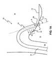
- FIG. 1Ais a side view of an ablation system.
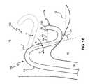
- FIG. 1Bis a side view of an ablation system including a flexible distal portion in accordance with the present invention.
- FIG. 1Cis another side view of the ablation system in accordance with the present invention.
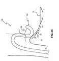
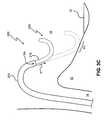
- FIGS. 2A-Eare side views of an ablation system being deployed, in accordance with the present invention.
- FIGS. 3A-Care side views of an alternative embodiment of an ablation system, in accordance with the present invention.
- FIG. 4Ais a side view of a first embodiment of an ablation system in accordance with the present invention.
- FIG. 4Bis an end view of the ablation system of FIG. 4 A.
- FIG. 5Ais a side view of another embodiment of an ablation system in accordance with the present invention.
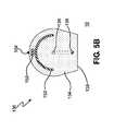
- FIG. 5Bis an end view of the ablation system of FIG. 4 A.
- FIG. 6Ais a side view of the ablation system of FIG. 5A shown with the distal end deflected to a first position.
- FIG. 6Bis a side view of an ablation system incorporating an alternative ablation device, in accordance with the present invention.
- FIG. 1Aa catheter 20 known in the art will be discussed. More specifically, FIG. 1A depicts catheter 20 advanced from a point proximate to the femoral vein (not shown), through the inferior vena cava 14 (IVC), and into the right atrium 16 , a distal tip 26 of catheter 20 engaging cardiac tissue 10 , between the IVC 14 and tricuspid valve 12 . For purposes of clarity, the depiction of the cardiac structure has been simplified.
- the catheter 20comprises a long tubular member 22 having a proximal portion (not shown) and distal portion 24 , the proximal portion operably attached to a handle portion (not shown).
- the distal portion 24includes, or otherwise incorporates, an ablation device 30 including one or more ablation elements.
- the one or more ablation elementsare arranged and configured to emit ablative energy in a direction generally away from an emission surface of the catheter 20 body, a portion of the radiating energy pattern generally designated by the arrows E 1 and E 2 , and the emission surface corresponding to the outer catheter surface from which the energy is emitted, directly or indirectly, with respect to catheter 20 .
- the emission surfacemay comprise the surface of one or more ablative elements embedded thereon, such as one or more electrodes adapted to contact target tissue and emit thermally conductive ablative energy.
- one or more ablative elementsmay be encased within the ablation device itself, the catheter structure allowing a substantial portion of the ablative energy to pass therethrough and engage target tissue.
- Such a systemhas the additional advantage, especially when the material within which the ablative elements are encased absorbs substantially none of the ablative energy which passes therethrough, of not charring or adhering to the target tissue, or causing other tissue damage generally associated with thermal conduction based systems.
- the steering system of catheter 20typically comprises at least one pull wire operably attached to a control means as part of the handle portion (not shown) and the distal portion 24 at an attachment point A. Operation of the control means results in the deflection of distal portion 24 of catheter 20 . Since the attachment point A is close to the distal end 26 of distal portion 24 it is often difficult for an operator, an electrophysiologist for example, to manipulate the distal portion 24 in such a way as to position the emitting surface substantially proximal and parallel to cardiac tissue 10 in order to create a desired lesion therein. As depicted in FIG. 1A, with an improperly positioned distal portion, a substantial portion of the ablative energy fails to effectively engage tissue 10 . Rather, the energy E 1 is absorbed in the blood.
- an approach angle ⁇is defined between a longitudinal axis line L of catheter 20 which passes through attachment point A and the surface of tissue 10 .
- Certain catheter systemsmay have distal energy delivery or ablation elements which are adapted to deliver an energy pattern from the distal end of the system toward a target tissue, distal end 26 toward tissue 10 for example, as depicted by arrows E 2 .
- catheter 20is positioned as shown in FIG. 1A, distal end 26 is not effectively placed perpendicularly in contact with tissue 10 .
- tip-firing energy E 2is not effectively transmitted to tissue 10 , resulting in poor ablation formation therein. Therefore, when approach angle ⁇ is about 0°, energy E 1 is most effectively transmitted to tissue 10 . Conversely, when approach angle ⁇ is about 90°, energy E 1 is most effectively transmitted to tissue 10 .
- energy patterns E 1 and E 2are generic in the sense that they do not depict energy patterns of ablation systems which require direct contact with the target tissue. However, as is discussed in more detail below, use of such systems is enhanced through the addition of structures and methods in accordance with the present invention. For example, if distal tip 26 of catheter 20 included an electrode which required direct contact with target tissue 10 , such a device would be difficult to maneuver and manipulate in such a way as to create numerous intermediate lesions as part of a long continuous lesion, especially during a beating heart procedure.
- catheter 100in accordance with the present invention is shown. As depicted in FIG. 1A with respect to catheter 20 , catheter 100 is shown passing through the inferior vena cava 14 and entering the right atrium 16 .
- Catheter 100comprises an elongated tubular body member 110 which leads to a distal portion 124 , and finally a distal end 126 .
- Distal portion 124comprises an ablation device 130 (not shown) including one or more ablation elements 136 (not shown) adapted to emit ablative energy therefrom toward a target tissue site.
- Catheter 100further incorporates a steering system 102 having a distal attachment point A located proximal to distal portion 124 and a proximal attachment point at handle H as shown in FIG. 1 C.
- a steering system 102having a distal attachment point A located proximal to distal portion 124 and a proximal attachment point at handle H as shown in FIG. 1 C.
- tensionis applied to a pull wire 104 which acts to deflect portion 124 substantially as shown. Therefore, as should be readily apparent from FIG. 1B, as the catheter 100 is deflected by steering system 102 from an initial position (shown in dashed line), with point A moving in a direction indicated by arrow D, the portion of catheter 100 distally located from point A is directed toward at least a portion of target tissue 10 .
- Such a configurationenables the distal portion 124 of catheter 100 to be placed proximal to target tissue 10 , allowing the emitted energy pattern E adjacent the point of contact to effectively impact upon target tissue 10
- angle ⁇is defined by the longitudinal axis line L of catheter 100 which passes through attachment point A and tissue 10 .
- the overall flexibility of distal portion 124is sufficiently greater than tubular member 110 , such that translation of pull wire 104 results in the deflection of portion 124 with respect to tubular member 110 , which substantially retains its form.
- the distal portion 124can be preformed or deflected to take on a curvilinear shape allowing ablation systems which require direct contact with the target tissue to be more easily moved in a controlled manner about the surface of the target tissue. For example, if one or more electrodes are placed along the distal portion 124 , one or more of the electrodes may be energized at any given time during movement of distal portion 124 about tissue 10 . Such a system offers better control and performance with respect to tip electrode systems which rely on moving the tip itself across the surface of the tissue.
- steering system 102may be incorporated into a separate guiding catheter (not shown), such that the ablation catheter, having an ablation device, can translate therein.
- the ablation devicemay be described as being deflected through operation of pull wire 104 , this does not necessarily mean the orientation of the ablation device is straight or linear.
- the ablation devicemay be curved to address the natural curvature of an internal organ or to assist in its proper placement, the ablation device directed to the target tissue through the use of a guiding catheter configured to restrict the ablation device to an orientation similar to the guiding catheter until the ablation device emerges and assumes its predetermined form.
- the ablation devicemay also incorporate a shielding means adapted to be opaque with respect to the corresponding ablative energy utilized, protecting surrounding tissues from the ablative energy. Additionally, the shielding device may be adapted to reflect at least a portion of ablation energy toward the target tissue site.
- Steering system 102may be any suitable steering system able to properly deflect catheter 100 to achieve the desired ablations described herein.
- Such steering systemsare disclosed in commonly owned and co-pending U.S. Patent Application entitled, “Catheter Having Improved Steering,” filed concurrently with the present application and hereby incorporated herein, in its entirety.
- catheter 100is steered, or otherwise directed, through the operation of steering system 102 . Since the steering system 102 is operably attached at point SA along catheter 100 , the catheter 100 structure distal to point SA remains substantially unaffected by catheter steering. As is discussed in greater detail below, with reference momentarily to FIG. 4A, once the distal portion 124 is directed toward a target area within the patient, within the right atrium for example, distal portion 124 is further deflected through operation of pull wire 104 .
- the steering system 102acts to deflect distal portion 124 and direct distal tip 126 in a direction generally toward the tricuspid valve 12 .
- the catheter 100is typically no longer advanced, however, distal portion 124 is continually deflected by operation of the steering system 102 , as described in greater detail above.
- the steering system 102results in further deflection of distal portion 124 with respect to the catheter member 110 , attachment point A moving generally in a direction noted by arrow M 1 .
- the distal portion 124is deflected through translation of the pull wire 104 , as described in greater detail above.
- the distal portion 124is further directed towards target tissue through continued operation of steering means 102 , as depicted in FIG. 2 D.
- the distal portion 124is steered, or otherwise further manipulated, until the a portion of the distal portion 124 is positioned proximate the target tissue 10 , indicated by position P 1 .
- ablative energyimpinges upon target tissue 10 to create a first ablation and corresponding lesion at position P 1 .
- catheter system 200comprises a guiding catheter 201 having at least one lumen passing therethrough, and a steering system 202 operably attaching to guiding catheter 201 generally at the attachment point SA.
- catheter system 200further comprises an ablation catheter 204 which translates through the at least one lumen of the guiding catheter 201 .
- Ablation catheter 204comprises a deflection means for deflecting the distal portion 224 thereof.
- the deflection meansmay be any suitable means, such as the deflection means described above with reference to catheter system 100 .
- the deflection meanscomprises a preformed or preshaped support member 250 encased within a portion of distal portion 224 .
- Member 250when no external forces are acting upon distal portion 224 , acts to deflect distal portion 224 to its preformed or preshaped orientation.
- the flexibility of member 250is somewhat less than that of guiding catheter 201 , such that as the distal portion 224 exits the distal opening of catheter 201 , distal portion 224 takes on the preformed shape of member 250 , as is discussed in more detail below.
- Support member 250may be formed having any suitable cross-sectional geometry including, but not limited to, circular, square, elliptical, or rectangular.
- the cross-sectional geometrymay be in the form of a rectangle limiting its deflection to the geometric plane passing through the longitudinal axis of the ablation catheter 204 during deflection of distal portion 224 .
- the distal portion 224may be more precisely placed upon target tissue.
- catheter system 200requires introduction of the catheter system into a patient's body, through the vasculature for example, and advanced until a distal portion is proximate target tissue to be ablated. Once the distal portion is in place, the catheter system 200 can be further manipulated to allow for ablation of the target tissue and formation of one or more desired lesions.
- guiding catheter 201 of catheter system 200is entered into the patient's vasculature, proximate to the femoral vein for example, and advanced into the IVC 14 until a distal portion 203 of catheter 201 is within the right atrium 16 , substantially as shown.
- the ablation catheter 204is translated through the at least one lumen of catheter 201 in a direction indicated by arrow M until a distal end of catheter 204 is positioned adjacent the distal opening of guiding catheter 201 , as generally depicted by FIG. 3 A.
- the ablation catheter 204is further advanced by operation of the advancement means by the user allowing the distal portion 224 to exit the distal opening of the guiding catheter 201 .
- the support member 250acts to deflect the distal portion 204 into a predetermined shape, as discussed above.
- the distal portion 224further takes on the predetermined shape of support member 250 until the final shape is achieved.
- FIG. 3Cdepicts the distal portion 224 of ablation catheter 204 in a semi-circular shape. It should be apparent that other shapes can be selected, these shapes being directly based on the target tissue selected.
- the ablation catheter 204is further advanced until at least a portion of distal portion 224 engages or is otherwise proximate to the target tissue.
- An exemplary positionis shown in dashed line in FIG. 3C, distal portion 224 engages target tissue 10 generally at the position indicated by P 1 .
- the steering system 201 of guiding catheter 201is further manipulated by the User to further move distal portion 224 across target tissue 10 , creating intermediate lesions as part of a desired lesion path as further discussed above with respect to catheter system 100 .
- catheter 100 Ahaving a deflectable distal portion in accordance with the present invention will be discussed in greater detail.
- catheter 100 Acomprises elongated tubular member 110 having at least one lumen passing therethrough.
- the tubular member 110ends in distal portion 124 .
- distal portion 124includes ablation device 130 comprising ablation element 136 .
- Ablation element 136is coupled to a transmission medium adapted for transmission of ablative energy from an energy source, a microwave generator for example.
- the transmission mediummay comprise, for illustration purposes only, a center conductor which is electrically coupled to a proximal end of ablation element 136 , an outer conductor and an insulating material therebetween.
- the transmission mediummay be a coaxial cable adapted to transmit energy therethrough to ablation element 136 at predetermined power levels sufficient for ablating the target tissue.
- exemplar modalitiesmay include one or more optical fibers as part of a laser ablation system, metallic wires or coaxial cable for an ultrasound or RF ablation system, and tubular members having passages therethrough for fluid or gas agents utilized by cryogenic ablation systems.
- ablation element 136is depicted as a linear antenna structure, any suitable structure can be used including, but not limited to, a helical antenna, an isolated monopole antenna, a lossy transmission line, or an exposed monopole antenna.
- the ablation element 136can be formed from any suitable material including, but not limited to, spring steel, beryllium copper, or silver-plated copper.
- the diameter of ablation element 136may be from about 0.005 to about 0.030 inches, and more preferably from about 0.013 to about 0.020 inches.
- catheter 100 Aalso includes pull wire 104 which has distal and proximal ends, the distal end operably attached to the handle portion (not shown) and the proximal end fixedly attached to the catheter 100 A at or near a distal tip 126 , designated as attachment point DA.
- the pull wire 104exits the tubular member 110 at or near the distal portion 124 through opening 106 and travels along the exterior of member 110 to the attachment point DA, as discussed immediately above.
- FIGS. 4 and 5depict pull wire 104 loosely placed within catheter 100
- pull wire 104could be enclosed within a separate tubular member 104 A (not shown).
- Member 104 Awould preferably run the length of catheter 100 , the proximal end fixedly attached to the handle portion (not shown) and the distal end fixedly attached to catheter 100 structure.
- member 104 Acould be part of the outer catheter 100 structure, fixedly attached to and integral to the structure along the entire length of catheter 100 . In this way, deflection forces associated with distal portion 124 can be transmitted directly to the handle portion, preventing undesirable deflection of catheter 100 and any tissue damage related thereto.
- Distal portion 124may optionally comprise a flexible support member 150 .
- Support member 150runs substantially the length of distal portion 124 , with a proximal end of member 150 fixedly attached to catheter 100 .
- Support member 150preferably has a rectangular cross-section encouraging deflecting of the distal portion 124 along one plane.
- Support member 150also acts to define a minimum radius of curvature to ensure consistent deflection of distal portion 124 along its length.
- the catheter system 100 Bis similar to system 100 A except for distal portion 124 .
- Distal portion 124 of catheter 100 Bfurther comprises a shielding means 152 adapted to shield surrounding tissue from ablative energy emitted therefrom.
- shielding means 152may act to absorb ablative energy, microwave energy in this specific case, or reflect and redirect the ablative energy toward the target tissue to enhance ablation, reflection of the energy being a function of the construction material of shielding means 152 and redirection of the energy being a function of the geometric shape of shielding means 152 .
- shielding means 152acts to reflect at least a portion of the energy emitted by ablation element 136 toward target tissue, tissue 10 for example, resulting in more efficient ablation of the tissue.
- shielding means 152is shown having a curvilinear geometric shape, shielding means 152 may also be substantially planar in construction, formed from metallic foil for example.
- shielding means 152may be constructed from a metallic wire mesh of copper, the wire mesh having wire spacing sufficient to prohibit passage of electromagnetic energy therethrough.
- a catheter 100 Bis depicted having distal portion 124 comprising ablation device 130 similar to that depicted in FIGS. 5A and 5B. As shown, distal portion 124 is deflected to a first position through translation of pull wire 104 . Once deflected, the ablation device 130 of catheter 100 B emits an ablative energy pattern as depicted by area E 1 . It should be understood, as with other depictions described herein, the energy pattern E 1 may be depicted in a planar view, such as in FIG. 6A, however, the ablative energy emitted has three-dimensional characteristics.
- the angle of approach ⁇ of catheter 100 Bbecomes less significant.
- the longitudinal axis L of catheter member 110which passes through attachment point A generally defines an attack angle ⁇ with respect to the target tissue, tissue 10 for example.
- the first and second positionare exemplary positions depicting energy dispersion from between approximately 180° to about 270°. It should be understood, however, that energy dispersion ranges could vary from approximately 0° to about 270° with reference to the proximal end of portion 124 , depending on the needs of the user, a surgeon for example. Additionally, it should be noted that while the ablation device 130 has been described as having a substantially circular configuration, other configurations are contemplated within the scope of the present invention to allow the User to ablate tissues of differing geometries.
- the shielding device 152may be adapted to control the geometry of deflection with respect to the distal portion 124 . Additionally, as stated above, the shielding means 152 may be configured such that the flexibility changes along its longitudinal axis resulting in different geometric configurations when distal portion 124 is deflected.
- catheter 100 Cincorporating an alternative ablation device is shown.
- Catheter 100 Chas a distal portion 124 including an ablation device comprising at least one radio frequency (RF) electrode 136 A-E operably controlled by the User through controlling means 140 .
- the electrodes 136 A-E of ablation device 130define an energy pattern depicted by E, shown in dashed line.
- Controlling means 140controls the application of energy to the electrodes 136 A-E, either alone, as a group of one or more, or the entire group.
- controlling means 140 of catheter 100 Cmay comprise one or more electrically conductive wires operably connected to electrodes 136 A-E and the handle portion (not shown). The User would apply ablative energy to target tissue through the direction of energy through one or more electrodes 136 A-E via controlling means 140 .
- the ablation device 130 of distal portion 124 of catheter 100 Cmay comprise more or less RF electrodes further defining an appropriate energy pattern E.
- the RF electrodes 136 A-Emay be in the form of a coiled spring such that the RF electrodes themselves may individually deflect as the distal portion 124 deflects. While the RF electrodes are shown in a spaced-apart relationship with respect to each other, electrodes 136 A-E may be positioned in close proximity with respect to each other, further defining energy dispersion. Additionally, each RF electrode 136 A-E may be controlled separately through control means 140 , further controlling or defining the energy dispersion area.
- the electrodes 136 A-Emay be semi-circular defining an energy pattern which is directed 180° about the longitudinal axis of the device, essentially defining a side-firing device which, when the distal portion is deflected, can transform partially or totally into a distal firing device.
- the desired resultant long continuous lesionmay comprise the creation of fewer or greater intermediate lesions than described above.
- ablation device 130may also include an energy shielding means adapted to be opaque to the ablative energy utilized, such that, tissue adjacent to target tissue 10 , for example, is protected from the ablative energy.
- the energy shielding meanscan be further adapted to reflect the ablative energy in a predetermined and desirable fashion as to focus the ablative energy at a desired region of the target tissue 10 , whereby the lesion characteristics can be better controlled.
- the shielding meansmay be formed to reflect and direct microwave energy in a relatively thin line along the longitudinal axis of the antenna, resulting in the desired formation of a relatively thin long intermediate lesion.
- the shielding means of a cryo based systemmay be constructed from thermal isolating material, the shielding means 152 axially surrounding a substantial portion of ablative device 130 leaving only a relatively thin opening along the longitudinal axis of device 130 , corresponding to a desired lesion. The opening would be controllably directed toward target tissue 10 , as discussed above, to create an intermediate lesion.
- steering system 102may be constructed as to limit the deflection of intermediate portion 118 to one plane, ensuring, for example, that the opening of the cryo-based ablation device 130 , discussed immediately above, is directed toward target tissue 10 .
- ablative device 130is preferably adapted to emit microwave energy sufficient to ablate the target tissue upon which a lesion is desired
- other ablative energies utilized by an ablative device 130 in catheter 100may include, but is not limited to, one or more of the following energies, along or in combination: microwave energy, laser energy or other forms of light energy in both the visible and nonvisible range, radio frequency (RF) energy, ultrasonic energy, cryogenic energy, chemical agent, thermal energy, or any other energy which can be controllably emitted and directed at least towards a portion of a desired target tissue, transporting ablation energy to the target tissue at sufficient energy levels resulting in tissue ablation and corresponding lesion formation.
- RFradio frequency
- One exemplary ablation device 130comprises a monopole microwave antenna as disclosed and further described in commonly owned U.S. Pat. No. 6,277,113, entitled “Monopole Tip for Ablation Catheter and Methods for Using Same,” which is hereby incorporated herein by reference, in its entirety.
- ablation device 130may comprise other microwave antenna structures as disclosed and further described in commonly owned U.S. Pat. No. 6,245,062, entitled “Directional Reflector Shield Assembly for a Microwave Ablation Instrument,” U.S. patent application Ser. No. 09/484,548, filed Jan. 18, 2000, entitled “Microwave Ablation Instrument With Flexible Antenna Assembly and Method”, and U.S. patent application Ser. No. 09/751,472, filed Dec. 28, 2000, entitled “A Tissue Ablation Apparatus with a Sliding Ablation Instrument and Method,” all hereby incorporated herein by reference, each in its entirety.
- catheter 100may further comprise one or more electrodes strategically placed upon the distal portion 124 to facilitate capture of certain electrophysiological signals.
- electrodesstrategically placed upon the distal portion 124 to facilitate capture of certain electrophysiological signals.
- Such signalsallow a User to determine tissue characteristics of a target tissue site and also provide confirmation that the distal portion 124 is properly positioned substantially proximal and parallel to a target tissue, for example.
- Such electrode arrangement systemsmay be similar to those disclosed in U.S. patent application Ser. No. 09/548,331, filed Apr. 12, 2000, entitled “Electrode Arrangement for Use in A Medical Instrument,” hereby incorporated herein by reference, in its entirety.
- tissue ablationswithin the right atrium of the heart
- the ablation systems disclosed hereinmay just as easily be applied to ablation of other tissues, such as the tissue surrounding the sinus cavities for example.
- the tissue ablationsmay be performed through either open surgery techniques or through minimal invasive techniques.
Landscapes
- Health & Medical Sciences (AREA)
- Life Sciences & Earth Sciences (AREA)
- Surgery (AREA)
- Engineering & Computer Science (AREA)
- Plasma & Fusion (AREA)
- Medical Informatics (AREA)
- Otolaryngology (AREA)
- Physics & Mathematics (AREA)
- Cardiology (AREA)
- Biomedical Technology (AREA)
- Heart & Thoracic Surgery (AREA)
- Nuclear Medicine, Radiotherapy & Molecular Imaging (AREA)
- Molecular Biology (AREA)
- Animal Behavior & Ethology (AREA)
- General Health & Medical Sciences (AREA)
- Public Health (AREA)
- Veterinary Medicine (AREA)
- Surgical Instruments (AREA)
Abstract
Description
Claims (9)
Priority Applications (3)
| Application Number | Priority Date | Filing Date | Title |
|---|---|---|---|
| US10/039,873US6817999B2 (en) | 2002-01-03 | 2002-01-03 | Flexible device for ablation of biological tissue |
| PCT/US2003/000117WO2003057056A1 (en) | 2002-01-03 | 2003-01-02 | Flexible device for ablation of biological tissue |
| AU2003202861AAU2003202861A1 (en) | 2002-01-03 | 2003-01-02 | Flexible device for ablation of biological tissue |
Applications Claiming Priority (1)
| Application Number | Priority Date | Filing Date | Title |
|---|---|---|---|
| US10/039,873US6817999B2 (en) | 2002-01-03 | 2002-01-03 | Flexible device for ablation of biological tissue |
Publications (2)
| Publication Number | Publication Date |
|---|---|
| US20030125730A1 US20030125730A1 (en) | 2003-07-03 |
| US6817999B2true US6817999B2 (en) | 2004-11-16 |
Family
ID=21907784
Family Applications (1)
| Application Number | Title | Priority Date | Filing Date |
|---|---|---|---|
| US10/039,873Expired - Fee RelatedUS6817999B2 (en) | 2002-01-03 | 2002-01-03 | Flexible device for ablation of biological tissue |
Country Status (3)
| Country | Link |
|---|---|
| US (1) | US6817999B2 (en) |
| AU (1) | AU2003202861A1 (en) |
| WO (1) | WO2003057056A1 (en) |
Cited By (75)
| Publication number | Priority date | Publication date | Assignee | Title |
|---|---|---|---|---|
| US20040181138A1 (en)* | 2003-03-12 | 2004-09-16 | Gerhard Hindricks | Method for treating tissue |
| US7137977B2 (en) | 2003-10-30 | 2006-11-21 | Medical Cv, Inc. | Atraumatic laser tip for atrial fibrillation treatment |
| US20070088349A1 (en)* | 2004-05-27 | 2007-04-19 | Belhe Kedar R | Curved ablation catheter |
| US7232437B2 (en) | 2003-10-30 | 2007-06-19 | Medical Cv, Inc. | Assessment of lesion transmurality |
| US7238180B2 (en) | 2003-10-30 | 2007-07-03 | Medicalcv Inc. | Guided ablation with end-fire fiber |
| US7238179B2 (en) | 2003-10-30 | 2007-07-03 | Medical Cv, Inc. | Apparatus and method for guided ablation treatment |
| US20080086047A1 (en)* | 2003-03-12 | 2008-04-10 | Biosense Webster, Inc. | Deflectable catheter with hinge |
| US7467015B2 (en) | 2004-04-29 | 2008-12-16 | Neuwave Medical, Inc. | Segmented catheter for tissue ablation |
| US7470272B2 (en) | 1997-07-18 | 2008-12-30 | Medtronic, Inc. | Device and method for ablating tissue |
| US20100121319A1 (en)* | 2008-11-10 | 2010-05-13 | Microcube, Llc | Methods and devices for applying energy to bodily tissues |
| US20100125269A1 (en)* | 2008-10-21 | 2010-05-20 | Microcube, Limited Liability Corporation | Microwave treatment devices and methods |
| US20100137857A1 (en)* | 2008-10-21 | 2010-06-03 | Microcube, Limited Liability Corporation | Methods and devices for applying energy to bodily tissues |
| US7740627B2 (en) | 2005-04-29 | 2010-06-22 | Medtronic Cryocath Lp | Surgical method and apparatus for treating atrial fibrillation |
| US20110004205A1 (en)* | 2008-10-21 | 2011-01-06 | Chu Chun Yiu | Methods and devices for delivering microwave energy |
| WO2011017168A2 (en) | 2009-07-28 | 2011-02-10 | Neuwave Medical, Inc. | Energy delivery systems and uses thereof |
| US20110184400A1 (en)* | 2010-01-28 | 2011-07-28 | Medtronic Cryocath Lp | Triple balloon catheter |
| US20110184402A1 (en)* | 2009-11-02 | 2011-07-28 | Cpsi Biotech | Flexible Cryogenic Probe Tip |
| US20120172918A1 (en)* | 2010-12-30 | 2012-07-05 | Claret Medical, Inc. | Method of Accessing the Left Common Carotid Artery |
| US8672932B2 (en) | 2006-03-24 | 2014-03-18 | Neuwave Medical, Inc. | Center fed dipole for use with tissue ablation systems, devices and methods |
| US8672930B2 (en) | 2010-07-28 | 2014-03-18 | Medtronic Cryocath Lp | Endoluminal ablation cryoballoon and method |
| US8774913B2 (en) | 2002-04-08 | 2014-07-08 | Medtronic Ardian Luxembourg S.A.R.L. | Methods and apparatus for intravasculary-induced neuromodulation |
| US8834464B2 (en) | 1999-04-05 | 2014-09-16 | Mark T. Stewart | Ablation catheters and associated systems and methods |
| US8888773B2 (en) | 2012-05-11 | 2014-11-18 | Medtronic Ardian Luxembourg S.A.R.L. | Multi-electrode catheter assemblies for renal neuromodulation and associated systems and methods |
| US8932208B2 (en) | 2005-05-26 | 2015-01-13 | Maquet Cardiovascular Llc | Apparatus and methods for performing minimally-invasive surgical procedures |
| US8934978B2 (en) | 2002-04-08 | 2015-01-13 | Medtronic Ardian Luxembourg S.A.R.L. | Methods and apparatus for renal neuromodulation |
| US8956352B2 (en) | 2010-10-25 | 2015-02-17 | Medtronic Ardian Luxembourg S.A.R.L. | Catheter apparatuses having multi-electrode arrays for renal neuromodulation and associated systems and methods |
| US8974489B2 (en) | 2009-07-27 | 2015-03-10 | Claret Medical, Inc. | Dual endovascular filter and methods of use |
| US9084610B2 (en) | 2010-10-21 | 2015-07-21 | Medtronic Ardian Luxembourg S.A.R.L. | Catheter apparatuses, systems, and methods for renal neuromodulation |
| US9095321B2 (en) | 2012-11-21 | 2015-08-04 | Medtronic Ardian Luxembourg S.A.R.L. | Cryotherapeutic devices having integral multi-helical balloons and methods of making the same |
| US9179974B2 (en) | 2013-03-15 | 2015-11-10 | Medtronic Ardian Luxembourg S.A.R.L. | Helical push wire electrode |
| US9192438B2 (en) | 2011-12-21 | 2015-11-24 | Neuwave Medical, Inc. | Energy delivery systems and uses thereof |
| US9326843B2 (en) | 2009-01-16 | 2016-05-03 | Claret Medical, Inc. | Intravascular blood filters and methods of use |
| US9566144B2 (en) | 2015-04-22 | 2017-02-14 | Claret Medical, Inc. | Vascular filters, deflectors, and methods |
| US9636205B2 (en) | 2009-01-16 | 2017-05-02 | Claret Medical, Inc. | Intravascular blood filters and methods of use |
| US9707035B2 (en) | 2002-04-08 | 2017-07-18 | Medtronic Ardian Luxembourg S.A.R.L. | Methods for catheter-based renal neuromodulation |
| US9717554B2 (en) | 2012-03-26 | 2017-08-01 | Biosense Webster (Israel) Ltd. | Catheter with composite construction |
| WO2017180877A2 (en) | 2016-04-15 | 2017-10-19 | Neuwave Medical, Inc. | Systems and methods for energy delivery |
| US9861440B2 (en) | 2010-05-03 | 2018-01-09 | Neuwave Medical, Inc. | Energy delivery systems and uses thereof |
| US10058380B2 (en) | 2007-10-05 | 2018-08-28 | Maquet Cordiovascular Llc | Devices and methods for minimally-invasive surgical procedures |
| US10166069B2 (en) | 2014-01-27 | 2019-01-01 | Medtronic Ardian Luxembourg S.A.R.L. | Neuromodulation catheters having jacketed neuromodulation elements and related devices, systems, and methods |
| US10188829B2 (en) | 2012-10-22 | 2019-01-29 | Medtronic Ardian Luxembourg S.A.R.L. | Catheters with enhanced flexibility and associated devices, systems, and methods |
| US10342614B2 (en) | 2004-04-29 | 2019-07-09 | Wisconsin Alumni Research Foundation | Triaxial antenna for microwave tissue ablation |
| WO2019135135A1 (en) | 2018-01-03 | 2019-07-11 | Neuwave Medical, Inc. | Systems and methods for energy delivery |
| US10363092B2 (en) | 2006-03-24 | 2019-07-30 | Neuwave Medical, Inc. | Transmission line with heat transfer ability |
| US10376314B2 (en) | 2006-07-14 | 2019-08-13 | Neuwave Medical, Inc. | Energy delivery systems and uses thereof |
| WO2019159040A1 (en) | 2018-02-15 | 2019-08-22 | Neuwave Medical, Inc. | Energy delivery device |
| WO2019159041A1 (en) | 2018-02-15 | 2019-08-22 | Neuwave Medical, Inc. | Compositions and methods for directing endoscopic devices |
| WO2019162786A1 (en) | 2018-02-26 | 2019-08-29 | Neuwave Medical, Inc. | Energy delivery devices with flexible and adjustable tips |
| US10548663B2 (en) | 2013-05-18 | 2020-02-04 | Medtronic Ardian Luxembourg S.A.R.L. | Neuromodulation catheters with shafts for enhanced flexibility and control and associated devices, systems, and methods |
| EP3626194A1 (en) | 2006-07-14 | 2020-03-25 | Neuwave Medical, Inc. | Energy delivery system |
| US10639099B2 (en) | 2012-05-25 | 2020-05-05 | Biosense Webster (Israel), Ltd. | Catheter having a distal section with spring sections for biased deflection |
| WO2020109999A1 (en) | 2018-11-27 | 2020-06-04 | Neuwave Medical, Inc. | Endoscopic system for energy delivery |
| WO2020121279A1 (en) | 2018-12-13 | 2020-06-18 | Neuwave Medical, Inc. | Energy delivery devices and related systems |
| US10736690B2 (en) | 2014-04-24 | 2020-08-11 | Medtronic Ardian Luxembourg S.A.R.L. | Neuromodulation catheters and associated systems and methods |
| US10743977B2 (en) | 2009-01-16 | 2020-08-18 | Boston Scientific Scimed, Inc. | Intravascular blood filter |
| WO2020183262A1 (en) | 2019-03-08 | 2020-09-17 | Neuwave Medical, Inc. | Systems and methods for energy delivery |
| EP3747391A1 (en) | 2015-10-26 | 2020-12-09 | Neuwave Medical, Inc. | Apparatuses for securing a medical device and related methods thereof |
| US10952792B2 (en) | 2015-10-26 | 2021-03-23 | Neuwave Medical, Inc. | Energy delivery systems and uses thereof |
| US11154390B2 (en) | 2017-12-19 | 2021-10-26 | Claret Medical, Inc. | Systems for protection of the cerebral vasculature during a cardiac procedure |
| US11191630B2 (en) | 2017-10-27 | 2021-12-07 | Claret Medical, Inc. | Systems and methods for protecting the cerebral vasculature |
| US11213678B2 (en) | 2013-09-09 | 2022-01-04 | Medtronic Ardian Luxembourg S.A.R.L. | Method of manufacturing a medical device for neuromodulation |
| US11219484B2 (en) | 2008-10-21 | 2022-01-11 | Microcube, Llc | Methods and devices for delivering microwave energy |
| US11234751B2 (en) | 2009-07-31 | 2022-02-01 | Case Western Reserve University | Characterizing ablation lesions using optical coherence tomography (OCT) |
| US11291503B2 (en) | 2008-10-21 | 2022-04-05 | Microcube, Llc | Microwave treatment devices and methods |
| US11337790B2 (en) | 2017-02-22 | 2022-05-24 | Boston Scientific Scimed, Inc. | Systems and methods for protecting the cerebral vasculature |
| US11351023B2 (en) | 2018-08-21 | 2022-06-07 | Claret Medical, Inc. | Systems and methods for protecting the cerebral vasculature |
| US11389235B2 (en) | 2006-07-14 | 2022-07-19 | Neuwave Medical, Inc. | Energy delivery systems and uses thereof |
| US11439491B2 (en) | 2018-04-26 | 2022-09-13 | Claret Medical, Inc. | Systems and methods for protecting the cerebral vasculature |
| US11471650B2 (en) | 2019-09-20 | 2022-10-18 | Biosense Webster (Israel) Ltd. | Mechanism for manipulating a puller wire |
| US11607301B2 (en) | 2009-01-16 | 2023-03-21 | Boston Scientific Scimed, Inc. | Intravascular blood filters and methods of use |
| WO2023047218A1 (en) | 2021-09-22 | 2023-03-30 | Neuwave Medical, Inc. | Systems and methods for real-time image-based device localization |
| WO2023156965A1 (en) | 2022-02-18 | 2023-08-24 | Neuwave Medical, Inc. | Coupling devices and related systems |
| WO2024176173A1 (en) | 2023-02-24 | 2024-08-29 | Neuwave Medical, Inc. | Temperature regulating devices and related systems and methods |
| US12150851B2 (en) | 2010-12-30 | 2024-11-26 | Claret Medical, Inc. | Method of isolating the cerebral circulation during a cardiac procedure |
| US12239367B2 (en) | 2019-06-25 | 2025-03-04 | Microcube, Llc | Methods and devices for generating and delivering shaped microwave fields |
Families Citing this family (38)
| Publication number | Priority date | Publication date | Assignee | Title |
|---|---|---|---|---|
| US6447443B1 (en) | 2001-01-13 | 2002-09-10 | Medtronic, Inc. | Method for organ positioning and stabilization |
| US6932811B2 (en) | 2000-04-27 | 2005-08-23 | Atricure, Inc. | Transmural ablation device with integral EKG sensor |
| US6905498B2 (en) | 2000-04-27 | 2005-06-14 | Atricure Inc. | Transmural ablation device with EKG sensor and pacing electrode |
| US20020107514A1 (en) | 2000-04-27 | 2002-08-08 | Hooven Michael D. | Transmural ablation device with parallel jaws |
| US6546935B2 (en) | 2000-04-27 | 2003-04-15 | Atricure, Inc. | Method for transmural ablation |
| US7628780B2 (en) | 2001-01-13 | 2009-12-08 | Medtronic, Inc. | Devices and methods for interstitial injection of biologic agents into tissue |
| US7740623B2 (en) | 2001-01-13 | 2010-06-22 | Medtronic, Inc. | Devices and methods for interstitial injection of biologic agents into tissue |
| US20040138621A1 (en) | 2003-01-14 | 2004-07-15 | Jahns Scott E. | Devices and methods for interstitial injection of biologic agents into tissue |
| EP1542587B1 (en) | 2002-08-24 | 2011-04-27 | St. Jude Medical, Atrial Fibrillation Division, Inc. | Method and apparatus for locating the fossa ovalis and performing transseptal puncture |
| US7291161B2 (en) | 2002-10-02 | 2007-11-06 | Atricure, Inc. | Articulated clamping member |
| US7288092B2 (en) | 2003-04-23 | 2007-10-30 | Atricure, Inc. | Method and apparatus for ablating cardiac tissue with guide facility |
| US7530980B2 (en) | 2004-04-14 | 2009-05-12 | Atricure, Inc | Bipolar transmural ablation method and apparatus |
| WO2005120376A2 (en) | 2004-06-02 | 2005-12-22 | Medtronic, Inc. | Ablation device with jaws |
| US20060089637A1 (en)* | 2004-10-14 | 2006-04-27 | Werneth Randell L | Ablation catheter |
| US8617152B2 (en) | 2004-11-15 | 2013-12-31 | Medtronic Ablation Frontiers Llc | Ablation system with feedback |
| US7468062B2 (en) | 2004-11-24 | 2008-12-23 | Ablation Frontiers, Inc. | Atrial ablation catheter adapted for treatment of septal wall arrhythmogenic foci and method of use |
| US7429261B2 (en) | 2004-11-24 | 2008-09-30 | Ablation Frontiers, Inc. | Atrial ablation catheter and method of use |
| EP2759276A1 (en) | 2005-06-20 | 2014-07-30 | Medtronic Ablation Frontiers LLC | Ablation catheter |
| AU2006268238A1 (en) | 2005-07-11 | 2007-01-18 | Medtronic Ablation Frontiers Llc | Low power tissue ablation system |
| US8657814B2 (en) | 2005-08-22 | 2014-02-25 | Medtronic Ablation Frontiers Llc | User interface for tissue ablation system |
| US8986298B2 (en) | 2006-11-17 | 2015-03-24 | Biosense Webster, Inc. | Catheter with omni-directional optical tip having isolated optical paths |
| US8979837B2 (en)* | 2007-04-04 | 2015-03-17 | St. Jude Medical, Atrial Fibrillation Division, Inc. | Flexible tip catheter with extended fluid lumen |
| US8187267B2 (en)* | 2007-05-23 | 2012-05-29 | St. Jude Medical, Atrial Fibrillation Division, Inc. | Ablation catheter with flexible tip and methods of making the same |
| US8764742B2 (en) | 2007-04-04 | 2014-07-01 | St. Jude Medical, Atrial Fibrillation Division, Inc. | Irrigated catheter |
| US8517999B2 (en) | 2007-04-04 | 2013-08-27 | St. Jude Medical, Atrial Fibrillation Division, Inc. | Irrigated catheter with improved fluid flow |
| US8641704B2 (en) | 2007-05-11 | 2014-02-04 | Medtronic Ablation Frontiers Llc | Ablation therapy system and method for treating continuous atrial fibrillation |
| US8974454B2 (en) | 2009-12-31 | 2015-03-10 | St. Jude Medical, Atrial Fibrillation Division, Inc. | Kit for non-invasive electrophysiology procedures and method of its use |
| US11395694B2 (en)* | 2009-05-07 | 2022-07-26 | St. Jude Medical, Llc | Irrigated ablation catheter with multiple segmented ablation electrodes |
| US8734440B2 (en)* | 2007-07-03 | 2014-05-27 | St. Jude Medical, Atrial Fibrillation Division, Inc. | Magnetically guided catheter |
| US10220187B2 (en) | 2010-06-16 | 2019-03-05 | St. Jude Medical, Llc | Ablation catheter having flexible tip with multiple flexible electrode segments |
| EP2173426B1 (en) | 2007-07-03 | 2016-04-20 | Irvine Biomedical, Inc. | Magnetically guided catheter |
| US20090093726A1 (en)* | 2007-10-04 | 2009-04-09 | Olympus Medical Systems Corp. | Cardiovascular ultrasound probe and ultrasound image system |
| US8500730B2 (en) | 2007-11-16 | 2013-08-06 | Biosense Webster, Inc. | Catheter with omni-directional optical tip having isolated optical paths |
| US20100249769A1 (en)* | 2009-03-24 | 2010-09-30 | Tyco Healthcare Group Lp | Apparatus for Tissue Sealing |
| US8328801B2 (en)* | 2009-08-17 | 2012-12-11 | Vivant Medical, Inc. | Surface ablation antenna with dielectric loading |
| US8992413B2 (en)* | 2011-05-31 | 2015-03-31 | Covidien Lp | Modified wet tip antenna design |
| US9717547B2 (en) | 2012-04-23 | 2017-08-01 | St. Jude Medical, Inc. | Ultrasonic lesion feedback, antipop monitoring, and force detection |
| CN106420048A (en)* | 2016-08-31 | 2017-02-22 | 赛诺微医疗科技(北京)有限公司 | Flexible microwave ablation antenna and microwave ablation needle using same |
Citations (13)
| Publication number | Priority date | Publication date | Assignee | Title |
|---|---|---|---|---|
| US5603697A (en)* | 1995-02-14 | 1997-02-18 | Fidus Medical Technology Corporation | Steering mechanism for catheters and methods for making same |
| US5755760A (en) | 1996-03-11 | 1998-05-26 | Medtronic, Inc. | Deflectable catheter |
| US5823955A (en) | 1995-11-20 | 1998-10-20 | Medtronic Cardiorhythm | Atrioventricular valve tissue ablation catheter and method |
| US5871525A (en)* | 1992-04-13 | 1999-02-16 | Ep Technologies, Inc. | Steerable ablation catheter system |
| US5921924A (en) | 1993-12-03 | 1999-07-13 | Avitall; Boaz | Mapping and ablation catheter system utilizing multiple control elements |
| US6090104A (en) | 1995-06-07 | 2000-07-18 | Cordis Webster, Inc. | Catheter with a spirally wound flat ribbon electrode |
| US6102886A (en)* | 1992-08-12 | 2000-08-15 | Vidamed, Inc. | Steerable medical probe with stylets |
| US6245062B1 (en) | 1998-10-23 | 2001-06-12 | Afx, Inc. | Directional reflector shield assembly for a microwave ablation instrument |
| EP1118310A1 (en) | 2000-01-18 | 2001-07-25 | AFX, Inc. | A microwave ablation instrument with flexible antenna assembly and method |
| US6277113B1 (en) | 1999-05-28 | 2001-08-21 | Afx, Inc. | Monopole tip for ablation catheter and methods for using same |
| US6471696B1 (en)* | 2000-04-12 | 2002-10-29 | Afx, Inc. | Microwave ablation instrument with a directional radiation pattern |
| US6514246B1 (en)* | 1993-10-14 | 2003-02-04 | Ep Technologies, Inc. | Systems and methods for forming large lesions in body tissue using curvilinear electrode elements |
| US6517568B1 (en)* | 1996-08-13 | 2003-02-11 | Oratec Interventions, Inc. | Method and apparatus for treating intervertebral discs |
- 2002
- 2002-01-03USUS10/039,873patent/US6817999B2/ennot_activeExpired - Fee Related
- 2003
- 2003-01-02WOPCT/US2003/000117patent/WO2003057056A1/ennot_activeApplication Discontinuation
- 2003-01-02AUAU2003202861Apatent/AU2003202861A1/ennot_activeAbandoned
Patent Citations (13)
| Publication number | Priority date | Publication date | Assignee | Title |
|---|---|---|---|---|
| US5871525A (en)* | 1992-04-13 | 1999-02-16 | Ep Technologies, Inc. | Steerable ablation catheter system |
| US6102886A (en)* | 1992-08-12 | 2000-08-15 | Vidamed, Inc. | Steerable medical probe with stylets |
| US6514246B1 (en)* | 1993-10-14 | 2003-02-04 | Ep Technologies, Inc. | Systems and methods for forming large lesions in body tissue using curvilinear electrode elements |
| US5921924A (en) | 1993-12-03 | 1999-07-13 | Avitall; Boaz | Mapping and ablation catheter system utilizing multiple control elements |
| US5603697A (en)* | 1995-02-14 | 1997-02-18 | Fidus Medical Technology Corporation | Steering mechanism for catheters and methods for making same |
| US6090104A (en) | 1995-06-07 | 2000-07-18 | Cordis Webster, Inc. | Catheter with a spirally wound flat ribbon electrode |
| US5823955A (en) | 1995-11-20 | 1998-10-20 | Medtronic Cardiorhythm | Atrioventricular valve tissue ablation catheter and method |
| US5755760A (en) | 1996-03-11 | 1998-05-26 | Medtronic, Inc. | Deflectable catheter |
| US6517568B1 (en)* | 1996-08-13 | 2003-02-11 | Oratec Interventions, Inc. | Method and apparatus for treating intervertebral discs |
| US6245062B1 (en) | 1998-10-23 | 2001-06-12 | Afx, Inc. | Directional reflector shield assembly for a microwave ablation instrument |
| US6277113B1 (en) | 1999-05-28 | 2001-08-21 | Afx, Inc. | Monopole tip for ablation catheter and methods for using same |
| EP1118310A1 (en) | 2000-01-18 | 2001-07-25 | AFX, Inc. | A microwave ablation instrument with flexible antenna assembly and method |
| US6471696B1 (en)* | 2000-04-12 | 2002-10-29 | Afx, Inc. | Microwave ablation instrument with a directional radiation pattern |
Non-Patent Citations (3)
| Title |
|---|
| Dany Berube, "Electrode Arrangement for Use in A Medical Instrument," U.S. patent application No. 09/548,331, filed Apr. 12, 2000. |
| Gauthier et al, "A Microwave Ablation Instrument With Flexible Antenna Assembly And Method" U.S. patent application No. 09/484,548 filed Jan. 18, 2000. |
| Mody et al "A Tissue Ablation and Apparatus with a Sliding Ablation Instrument and Method," U.S. patent application No. 09/751,472, filed Dec. 28, 2000. |
Cited By (175)
| Publication number | Priority date | Publication date | Assignee | Title |
|---|---|---|---|---|
| US7470272B2 (en) | 1997-07-18 | 2008-12-30 | Medtronic, Inc. | Device and method for ablating tissue |
| US7678111B2 (en) | 1997-07-18 | 2010-03-16 | Medtronic, Inc. | Device and method for ablating tissue |
| US9554848B2 (en) | 1999-04-05 | 2017-01-31 | Medtronic, Inc. | Ablation catheters and associated systems and methods |
| US8834464B2 (en) | 1999-04-05 | 2014-09-16 | Mark T. Stewart | Ablation catheters and associated systems and methods |
| US8774913B2 (en) | 2002-04-08 | 2014-07-08 | Medtronic Ardian Luxembourg S.A.R.L. | Methods and apparatus for intravasculary-induced neuromodulation |
| US9707035B2 (en) | 2002-04-08 | 2017-07-18 | Medtronic Ardian Luxembourg S.A.R.L. | Methods for catheter-based renal neuromodulation |
| US9289255B2 (en) | 2002-04-08 | 2016-03-22 | Medtronic Ardian Luxembourg S.A.R.L. | Methods and apparatus for renal neuromodulation |
| US8934978B2 (en) | 2002-04-08 | 2015-01-13 | Medtronic Ardian Luxembourg S.A.R.L. | Methods and apparatus for renal neuromodulation |
| US9675413B2 (en) | 2002-04-08 | 2017-06-13 | Medtronic Ardian Luxembourg S.A.R.L. | Methods and apparatus for renal neuromodulation |
| US9636482B2 (en) | 2003-03-12 | 2017-05-02 | Biosense Webster, Inc. | Deflectable catheter with hinge |
| US20080086047A1 (en)* | 2003-03-12 | 2008-04-10 | Biosense Webster, Inc. | Deflectable catheter with hinge |
| US10183150B2 (en) | 2003-03-12 | 2019-01-22 | Biosense Webster, Inc. | Deflectable catheter with hinge |
| US20040181138A1 (en)* | 2003-03-12 | 2004-09-16 | Gerhard Hindricks | Method for treating tissue |
| US8256428B2 (en)* | 2003-03-12 | 2012-09-04 | Biosense Webster, Inc. | Method for treating tissue |
| US10814100B2 (en) | 2003-03-12 | 2020-10-27 | Biosense Webster, Inc. | Deflectable catheter with hinge |
| US8764743B2 (en) | 2003-03-12 | 2014-07-01 | Biosense Webster, Inc. | Deflectable catheter with hinge |
| US7267674B2 (en) | 2003-10-30 | 2007-09-11 | Medical Cv, Inc. | Apparatus and method for laser treatment |
| US7238180B2 (en) | 2003-10-30 | 2007-07-03 | Medicalcv Inc. | Guided ablation with end-fire fiber |
| US7137977B2 (en) | 2003-10-30 | 2006-11-21 | Medical Cv, Inc. | Atraumatic laser tip for atrial fibrillation treatment |
| US7163534B2 (en) | 2003-10-30 | 2007-01-16 | Medical Cv, Inc. | Laser-based maze procedure for atrial fibrillation |
| US7338485B2 (en) | 2003-10-30 | 2008-03-04 | Medical Cv, Inc. | Cardiac lesions with continuity testing |
| US7169142B2 (en) | 2003-10-30 | 2007-01-30 | Medical Cv, Inc. | Malleable energy wand for maze procedure |
| US7238179B2 (en) | 2003-10-30 | 2007-07-03 | Medical Cv, Inc. | Apparatus and method for guided ablation treatment |
| US7232437B2 (en) | 2003-10-30 | 2007-06-19 | Medical Cv, Inc. | Assessment of lesion transmurality |
| US10342614B2 (en) | 2004-04-29 | 2019-07-09 | Wisconsin Alumni Research Foundation | Triaxial antenna for microwave tissue ablation |
| US7467015B2 (en) | 2004-04-29 | 2008-12-16 | Neuwave Medical, Inc. | Segmented catheter for tissue ablation |
| US8486062B2 (en) | 2004-05-27 | 2013-07-16 | St. Jude Medical, Atrial Fibrillation Division, Inc. | Curved ablation catheter |
| US20070088349A1 (en)* | 2004-05-27 | 2007-04-19 | Belhe Kedar R | Curved ablation catheter |
| US7740627B2 (en) | 2005-04-29 | 2010-06-22 | Medtronic Cryocath Lp | Surgical method and apparatus for treating atrial fibrillation |
| US8932208B2 (en) | 2005-05-26 | 2015-01-13 | Maquet Cardiovascular Llc | Apparatus and methods for performing minimally-invasive surgical procedures |
| US8672932B2 (en) | 2006-03-24 | 2014-03-18 | Neuwave Medical, Inc. | Center fed dipole for use with tissue ablation systems, devices and methods |
| US11944376B2 (en) | 2006-03-24 | 2024-04-02 | Neuwave Medical, Inc. | Transmission line with heat transfer ability |
| EP3797721A1 (en) | 2006-03-24 | 2021-03-31 | Neuwave Medical, Inc. | Transmission line with heat transfer ability |
| US10363092B2 (en) | 2006-03-24 | 2019-07-30 | Neuwave Medical, Inc. | Transmission line with heat transfer ability |
| US11596474B2 (en) | 2006-07-14 | 2023-03-07 | Neuwave Medical, Inc. | Energy delivery systems and uses thereof |
| US10376314B2 (en) | 2006-07-14 | 2019-08-13 | Neuwave Medical, Inc. | Energy delivery systems and uses thereof |
| US11389235B2 (en) | 2006-07-14 | 2022-07-19 | Neuwave Medical, Inc. | Energy delivery systems and uses thereof |
| US11576723B2 (en) | 2006-07-14 | 2023-02-14 | Neuwave Medical, Inc. | Energy delivery systems and uses thereof |
| US11576722B2 (en) | 2006-07-14 | 2023-02-14 | Neuwave Medical, Inc. | Energy delivery systems and uses thereof |
| EP3626194A1 (en) | 2006-07-14 | 2020-03-25 | Neuwave Medical, Inc. | Energy delivery system |
| US10058380B2 (en) | 2007-10-05 | 2018-08-28 | Maquet Cordiovascular Llc | Devices and methods for minimally-invasive surgical procedures |
| US10993766B2 (en) | 2007-10-05 | 2021-05-04 | Maquet Cardiovascular Llc | Devices and methods for minimally-invasive surgical procedures |
| US20100125269A1 (en)* | 2008-10-21 | 2010-05-20 | Microcube, Limited Liability Corporation | Microwave treatment devices and methods |
| US8968287B2 (en) | 2008-10-21 | 2015-03-03 | Microcube, Llc | Methods and devices for applying energy to bodily tissues |
| US11219484B2 (en) | 2008-10-21 | 2022-01-11 | Microcube, Llc | Methods and devices for delivering microwave energy |
| US12011220B2 (en) | 2008-10-21 | 2024-06-18 | Microcube, Llc | Microwave treatment devices and methods |
| US11291503B2 (en) | 2008-10-21 | 2022-04-05 | Microcube, Llc | Microwave treatment devices and methods |
| US8808281B2 (en)* | 2008-10-21 | 2014-08-19 | Microcube, Llc | Microwave treatment devices and methods |
| US11684418B2 (en) | 2008-10-21 | 2023-06-27 | Microcube, Llc | Methods and devices for applying energy to bodily tissues |
| US9980774B2 (en) | 2008-10-21 | 2018-05-29 | Microcube, Llc | Methods and devices for delivering microwave energy |
| US10869720B2 (en) | 2008-10-21 | 2020-12-22 | Microcube, Llc | Methods and devices for applying energy to bodily tissues |
| US20100137857A1 (en)* | 2008-10-21 | 2010-06-03 | Microcube, Limited Liability Corporation | Methods and devices for applying energy to bodily tissues |
| US10299859B2 (en) | 2008-10-21 | 2019-05-28 | Microcube, Llc | Methods and devices for delivering microwave energy |
| US9615882B2 (en) | 2008-10-21 | 2017-04-11 | Microcube, Llc | Methods and devices for applying energy to bodily tissues |
| US20110004205A1 (en)* | 2008-10-21 | 2011-01-06 | Chu Chun Yiu | Methods and devices for delivering microwave energy |
| US10470819B2 (en) | 2008-11-10 | 2019-11-12 | Microcube, Llc | Methods and devices for applying energy to bodily tissues |
| US11147619B2 (en) | 2008-11-10 | 2021-10-19 | Microcube, Llc | Methods and devices for applying energy to bodily tissues |
| US12144542B2 (en) | 2008-11-10 | 2024-11-19 | Microcube, Llc | Methods and devices for applying energy to bodily tissues |
| US9993293B2 (en) | 2008-11-10 | 2018-06-12 | Microcube, Llc | Methods and devices for applying energy to bodily tissues |
| US20100121319A1 (en)* | 2008-11-10 | 2010-05-13 | Microcube, Llc | Methods and devices for applying energy to bodily tissues |
| US11364106B2 (en) | 2009-01-16 | 2022-06-21 | Boston Scientific Scimed, Inc. | Intravascular blood filter |
| US9326843B2 (en) | 2009-01-16 | 2016-05-03 | Claret Medical, Inc. | Intravascular blood filters and methods of use |
| US10743977B2 (en) | 2009-01-16 | 2020-08-18 | Boston Scientific Scimed, Inc. | Intravascular blood filter |
| US9636205B2 (en) | 2009-01-16 | 2017-05-02 | Claret Medical, Inc. | Intravascular blood filters and methods of use |
| US12201507B2 (en) | 2009-01-16 | 2025-01-21 | Claret Medical, Inc. | Intravascular blood filters and methods of use |
| US11607301B2 (en) | 2009-01-16 | 2023-03-21 | Boston Scientific Scimed, Inc. | Intravascular blood filters and methods of use |
| US12048618B2 (en) | 2009-01-16 | 2024-07-30 | Boston Scientific Scimed, Inc. | Intravascular blood filter |
| US11284986B2 (en) | 2009-01-16 | 2022-03-29 | Claret Medical, Inc. | Intravascular blood filters and methods of use |
| US10130458B2 (en) | 2009-07-27 | 2018-11-20 | Claret Medical, Inc. | Dual endovascular filter and methods of use |
| US8974489B2 (en) | 2009-07-27 | 2015-03-10 | Claret Medical, Inc. | Dual endovascular filter and methods of use |
| US11191631B2 (en) | 2009-07-27 | 2021-12-07 | Boston Scientific Scimed, Inc. | Dual endovascular filter and methods of use |
| EP3228272A1 (en) | 2009-07-28 | 2017-10-11 | Neuwave Medical, Inc. | Ablation system |
| EP2859862A1 (en) | 2009-07-28 | 2015-04-15 | Neuwave Medical, Inc. | Ablation system |
| US9877783B2 (en) | 2009-07-28 | 2018-01-30 | Neuwave Medical, Inc. | Energy delivery systems and uses thereof |
| US11013557B2 (en) | 2009-07-28 | 2021-05-25 | Neuwave Medical, Inc. | Energy delivery systems and uses thereof |
| US9566115B2 (en) | 2009-07-28 | 2017-02-14 | Neuwave Medical, Inc. | Energy delivery systems and uses thereof |
| EP3549544A1 (en) | 2009-07-28 | 2019-10-09 | Neuwave Medical, Inc. | Ablation system |
| WO2011017168A2 (en) | 2009-07-28 | 2011-02-10 | Neuwave Medical, Inc. | Energy delivery systems and uses thereof |
| US10357312B2 (en) | 2009-07-28 | 2019-07-23 | Neuwave Medical, Inc. | Energy delivery systems and uses thereof |
| US9119649B2 (en) | 2009-07-28 | 2015-09-01 | Neuwave Medical, Inc. | Energy delivery systems and uses thereof |
| US12133671B2 (en) | 2009-07-31 | 2024-11-05 | Case Western Reserve University | Characterizing ablation lesions using optical coherence tomography (OCT) |
| US11234751B2 (en) | 2009-07-31 | 2022-02-01 | Case Western Reserve University | Characterizing ablation lesions using optical coherence tomography (OCT) |
| US20110184402A1 (en)* | 2009-11-02 | 2011-07-28 | Cpsi Biotech | Flexible Cryogenic Probe Tip |
| US20110184400A1 (en)* | 2010-01-28 | 2011-07-28 | Medtronic Cryocath Lp | Triple balloon catheter |
| US9743973B2 (en) | 2010-01-28 | 2017-08-29 | Medtronic Cryocath Lp | Triple balloon catheter |
| US8926602B2 (en) | 2010-01-28 | 2015-01-06 | Medtronic Cryocath Lp | Triple balloon catheter |
| EP3804651A1 (en) | 2010-05-03 | 2021-04-14 | Neuwave Medical, Inc. | Energy delivery systems |
| US9861440B2 (en) | 2010-05-03 | 2018-01-09 | Neuwave Medical, Inc. | Energy delivery systems and uses thereof |
| US10524862B2 (en) | 2010-05-03 | 2020-01-07 | Neuwave Medical, Inc. | Energy delivery systems and uses thereof |
| US11490960B2 (en) | 2010-05-03 | 2022-11-08 | Neuwave Medical, Inc. | Energy delivery systems and uses thereof |
| US10603106B2 (en) | 2010-05-03 | 2020-03-31 | Neuwave Medical, Inc. | Energy delivery systems and uses thereof |
| US12376903B2 (en) | 2010-05-03 | 2025-08-05 | Neuwave Medical, Inc. | Energy delivery systems and uses thereof |
| US9872729B2 (en) | 2010-05-03 | 2018-01-23 | Neuwave Medical, Inc. | Energy delivery systems and uses thereof |
| US8672930B2 (en) | 2010-07-28 | 2014-03-18 | Medtronic Cryocath Lp | Endoluminal ablation cryoballoon and method |
| US9855097B2 (en) | 2010-10-21 | 2018-01-02 | Medtronic Ardian Luxembourg S.A.R.L. | Catheter apparatuses, systems, and methods for renal neuromodulation |
| US9636173B2 (en) | 2010-10-21 | 2017-05-02 | Medtronic Ardian Luxembourg S.A.R.L. | Methods for renal neuromodulation |
| US9084610B2 (en) | 2010-10-21 | 2015-07-21 | Medtronic Ardian Luxembourg S.A.R.L. | Catheter apparatuses, systems, and methods for renal neuromodulation |
| US10342612B2 (en) | 2010-10-21 | 2019-07-09 | Medtronic Ardian Luxembourg S.A.R.L. | Catheter apparatuses, systems, and methods for renal neuromodulation |
| US10076382B2 (en) | 2010-10-25 | 2018-09-18 | Medtronic Ardian Luxembourg S.A.R.L. | Catheter apparatuses having multi-electrode arrays for renal neuromodulation and associated systems and methods |
| US8998894B2 (en) | 2010-10-25 | 2015-04-07 | Medtronic Ardian Luxembourg S.A.R.L. | Catheter apparatuses having multi-electrode arrays for renal neuromodulation and associated systems and methods |
| US8956352B2 (en) | 2010-10-25 | 2015-02-17 | Medtronic Ardian Luxembourg S.A.R.L. | Catheter apparatuses having multi-electrode arrays for renal neuromodulation and associated systems and methods |
| US11116572B2 (en) | 2010-10-25 | 2021-09-14 | Medtronic Ardian Luxembourg S.A.R.L. | Catheter apparatuses having multi-electrode arrays for renal neuromodulation and associated systems and methods |
| US9017364B2 (en) | 2010-12-30 | 2015-04-28 | Claret Medical, Inc. | Deflectable intravascular filter |
| US9980805B2 (en) | 2010-12-30 | 2018-05-29 | Claret Medical, Inc. | Aortic embolic protection device |
| US9055997B2 (en) | 2010-12-30 | 2015-06-16 | Claret Medical, Inc. | Method of isolating the cerebral circulation during a cardiac procedure |
| US10058411B2 (en) | 2010-12-30 | 2018-08-28 | Claret Madical, Inc. | Method of isolating the cerebral circulation during a cardiac procedure |
| US9943395B2 (en) | 2010-12-30 | 2018-04-17 | Claret Medical, Inc. | Deflectable intravascular filter |
| US9345565B2 (en)* | 2010-12-30 | 2016-05-24 | Claret Medical, Inc. | Steerable dual filter cerebral protection system |
| US20120172918A1 (en)* | 2010-12-30 | 2012-07-05 | Claret Medical, Inc. | Method of Accessing the Left Common Carotid Artery |
| US20120172917A1 (en)* | 2010-12-30 | 2012-07-05 | Claret Medical, Inc. | Steerable Dual Filter Cerebral Protection System |
| US9259306B2 (en) | 2010-12-30 | 2016-02-16 | Claret Medical, Inc. | Aortic embolic protection device |
| US8876796B2 (en)* | 2010-12-30 | 2014-11-04 | Claret Medical, Inc. | Method of accessing the left common carotid artery |
| US12150851B2 (en) | 2010-12-30 | 2024-11-26 | Claret Medical, Inc. | Method of isolating the cerebral circulation during a cardiac procedure |
| US11141258B2 (en) | 2010-12-30 | 2021-10-12 | Claret Medical, Inc. | Method of isolating the cerebral circulation during a cardiac procedure |
| US9492264B2 (en) | 2010-12-30 | 2016-11-15 | Claret Medical, Inc. | Embolic protection device for protecting the cerebral vasculature |
| US11638607B2 (en) | 2011-12-21 | 2023-05-02 | Neuwave Medical, Inc. | Energy delivery systems and uses thereof |
| EP3769712A1 (en) | 2011-12-21 | 2021-01-27 | Neuwave Medical, Inc. | Energy delivery systems |
| US9192438B2 (en) | 2011-12-21 | 2015-11-24 | Neuwave Medical, Inc. | Energy delivery systems and uses thereof |
| US10667860B2 (en) | 2011-12-21 | 2020-06-02 | Neuwave Medical, Inc. | Energy delivery systems and uses thereof |
| US10512503B2 (en) | 2012-03-26 | 2019-12-24 | Biosense Webster (Israel) Ltd. | Catheter with composite construction |
| US9717554B2 (en) | 2012-03-26 | 2017-08-01 | Biosense Webster (Israel) Ltd. | Catheter with composite construction |
| US11931100B2 (en) | 2012-03-26 | 2024-03-19 | Biosense Webster (Israel) Ltd. | Catheter with composite construction |
| US11737816B2 (en) | 2012-03-26 | 2023-08-29 | Biosense Webster (Israel) Ltd. | Catheter with composite construction |
| US8888773B2 (en) | 2012-05-11 | 2014-11-18 | Medtronic Ardian Luxembourg S.A.R.L. | Multi-electrode catheter assemblies for renal neuromodulation and associated systems and methods |
| US9138292B2 (en) | 2012-05-11 | 2015-09-22 | Medtronic Ardian Luxembourg S.A.R.L. | Multi-electrode catheter assemblies for renal neuromodulation and associated systems and methods |
| US10512504B2 (en) | 2012-05-11 | 2019-12-24 | Medtronic Ardian Luxembourg S.A.R.L. | Multi-electrode catheter assemblies for renal neuromodulation and associated systems and methods |
| US9855096B2 (en) | 2012-05-11 | 2018-01-02 | Medtronic Ardian Luxembourg S.A.R.L. | Multi-electrode catheter assemblies for renal neuromodulation and associated systems and methods |
| US9452017B2 (en) | 2012-05-11 | 2016-09-27 | Medtronic Ardian Luxembourg S.A.R.L. | Multi-electrode catheter assemblies for renal neuromodulation and associated systems and methods |
| US10639099B2 (en) | 2012-05-25 | 2020-05-05 | Biosense Webster (Israel), Ltd. | Catheter having a distal section with spring sections for biased deflection |
| US11147948B2 (en) | 2012-10-22 | 2021-10-19 | Medtronic Ardian Luxembourg S.A.R.L. | Catheters with enhanced flexibility and associated devices, systems, and methods |
| US10188829B2 (en) | 2012-10-22 | 2019-01-29 | Medtronic Ardian Luxembourg S.A.R.L. | Catheters with enhanced flexibility and associated devices, systems, and methods |
| US9095321B2 (en) | 2012-11-21 | 2015-08-04 | Medtronic Ardian Luxembourg S.A.R.L. | Cryotherapeutic devices having integral multi-helical balloons and methods of making the same |
| US10792098B2 (en) | 2013-03-15 | 2020-10-06 | Medtronic Ardian Luxembourg S.A.R.L. | Helical push wire electrode |
| US9888961B2 (en) | 2013-03-15 | 2018-02-13 | Medtronic Ardian Luxembourg S.A.R.L. | Helical push wire electrode |
| US9179974B2 (en) | 2013-03-15 | 2015-11-10 | Medtronic Ardian Luxembourg S.A.R.L. | Helical push wire electrode |
| US10548663B2 (en) | 2013-05-18 | 2020-02-04 | Medtronic Ardian Luxembourg S.A.R.L. | Neuromodulation catheters with shafts for enhanced flexibility and control and associated devices, systems, and methods |
| US11213678B2 (en) | 2013-09-09 | 2022-01-04 | Medtronic Ardian Luxembourg S.A.R.L. | Method of manufacturing a medical device for neuromodulation |
| US10166069B2 (en) | 2014-01-27 | 2019-01-01 | Medtronic Ardian Luxembourg S.A.R.L. | Neuromodulation catheters having jacketed neuromodulation elements and related devices, systems, and methods |
| US11464563B2 (en) | 2014-04-24 | 2022-10-11 | Medtronic Ardian Luxembourg S.A.R.L. | Neuromodulation catheters and associated systems and methods |
| US10736690B2 (en) | 2014-04-24 | 2020-08-11 | Medtronic Ardian Luxembourg S.A.R.L. | Neuromodulation catheters and associated systems and methods |
| US9566144B2 (en) | 2015-04-22 | 2017-02-14 | Claret Medical, Inc. | Vascular filters, deflectors, and methods |
| US10449028B2 (en) | 2015-04-22 | 2019-10-22 | Claret Medical, Inc. | Vascular filters, deflectors, and methods |
| EP3841994A1 (en) | 2015-10-26 | 2021-06-30 | Neuwave Medical, Inc. | Energy delivery systems |
| US11678935B2 (en) | 2015-10-26 | 2023-06-20 | Neuwave Medical, Inc. | Energy delivery systems and uses thereof |
| EP3747391A1 (en) | 2015-10-26 | 2020-12-09 | Neuwave Medical, Inc. | Apparatuses for securing a medical device and related methods thereof |
| US10952792B2 (en) | 2015-10-26 | 2021-03-23 | Neuwave Medical, Inc. | Energy delivery systems and uses thereof |
| WO2017180877A2 (en) | 2016-04-15 | 2017-10-19 | Neuwave Medical, Inc. | Systems and methods for energy delivery |
| EP3808302A1 (en) | 2016-04-15 | 2021-04-21 | Neuwave Medical, Inc. | System for energy delivery |
| US11395699B2 (en) | 2016-04-15 | 2022-07-26 | Neuwave Medical, Inc. | Systems and methods for energy delivery |
| US10531917B2 (en) | 2016-04-15 | 2020-01-14 | Neuwave Medical, Inc. | Systems and methods for energy delivery |
| US11337790B2 (en) | 2017-02-22 | 2022-05-24 | Boston Scientific Scimed, Inc. | Systems and methods for protecting the cerebral vasculature |
| US12097108B2 (en) | 2017-10-27 | 2024-09-24 | Claret Medical, Inc. | Systems and methods for protecting the cerebral vasculature |
| US11191630B2 (en) | 2017-10-27 | 2021-12-07 | Claret Medical, Inc. | Systems and methods for protecting the cerebral vasculature |
| US11154390B2 (en) | 2017-12-19 | 2021-10-26 | Claret Medical, Inc. | Systems for protection of the cerebral vasculature during a cardiac procedure |
| US12064332B2 (en) | 2017-12-19 | 2024-08-20 | Claret Medical, Inc. | Systems and methods for protecting the cerebral vasculature |
| WO2019135135A1 (en) | 2018-01-03 | 2019-07-11 | Neuwave Medical, Inc. | Systems and methods for energy delivery |
| WO2019159041A1 (en) | 2018-02-15 | 2019-08-22 | Neuwave Medical, Inc. | Compositions and methods for directing endoscopic devices |
| WO2019159040A1 (en) | 2018-02-15 | 2019-08-22 | Neuwave Medical, Inc. | Energy delivery device |
| US12171490B2 (en) | 2018-02-26 | 2024-12-24 | Neuwave Medical, Inc. | Energy delivery devices with flexible and adjustable tips |
| US11672596B2 (en) | 2018-02-26 | 2023-06-13 | Neuwave Medical, Inc. | Energy delivery devices with flexible and adjustable tips |
| WO2019162786A1 (en) | 2018-02-26 | 2019-08-29 | Neuwave Medical, Inc. | Energy delivery devices with flexible and adjustable tips |
| US11439491B2 (en) | 2018-04-26 | 2022-09-13 | Claret Medical, Inc. | Systems and methods for protecting the cerebral vasculature |
| US12409022B2 (en) | 2018-04-26 | 2025-09-09 | Claret Medical, Inc. | Systems and methods for protecting the cerebral vasculature |
| US11351023B2 (en) | 2018-08-21 | 2022-06-07 | Claret Medical, Inc. | Systems and methods for protecting the cerebral vasculature |
| WO2020109999A1 (en) | 2018-11-27 | 2020-06-04 | Neuwave Medical, Inc. | Endoscopic system for energy delivery |
| WO2020121279A1 (en) | 2018-12-13 | 2020-06-18 | Neuwave Medical, Inc. | Energy delivery devices and related systems |
| US11832880B2 (en) | 2018-12-13 | 2023-12-05 | Neuwave Medical, Inc. | Energy delivery devices and related systems and methods thereof |
| WO2020183262A1 (en) | 2019-03-08 | 2020-09-17 | Neuwave Medical, Inc. | Systems and methods for energy delivery |
| US11832879B2 (en) | 2019-03-08 | 2023-12-05 | Neuwave Medical, Inc. | Systems and methods for energy delivery |
| US12239367B2 (en) | 2019-06-25 | 2025-03-04 | Microcube, Llc | Methods and devices for generating and delivering shaped microwave fields |
| US11471650B2 (en) | 2019-09-20 | 2022-10-18 | Biosense Webster (Israel) Ltd. | Mechanism for manipulating a puller wire |
| US11964115B2 (en) | 2019-09-20 | 2024-04-23 | Biosense Webster (Israel) Ltd. | Mechanism for manipulating a puller wire |
| WO2023047218A1 (en) | 2021-09-22 | 2023-03-30 | Neuwave Medical, Inc. | Systems and methods for real-time image-based device localization |
| WO2023156965A1 (en) | 2022-02-18 | 2023-08-24 | Neuwave Medical, Inc. | Coupling devices and related systems |
| WO2024176173A1 (en) | 2023-02-24 | 2024-08-29 | Neuwave Medical, Inc. | Temperature regulating devices and related systems and methods |
Also Published As
| Publication number | Publication date |
|---|---|
| WO2003057056A1 (en) | 2003-07-17 |
| WO2003057056A9 (en) | 2004-05-13 |
| US20030125730A1 (en) | 2003-07-03 |
| AU2003202861A1 (en) | 2003-07-24 |
Similar Documents
| Publication | Publication Date | Title |
|---|---|---|
| US6817999B2 (en) | Flexible device for ablation of biological tissue | |
| US6893436B2 (en) | Ablation instrument having a flexible distal portion | |
| US7099717B2 (en) | Catheter having improved steering | |
| US9925002B2 (en) | Articulating ablation device and method | |
| EP1186274B1 (en) | Surgical microwave ablation assembly | |
| US6802840B2 (en) | Medical instrument positioning tool and method | |
| EP1608279B1 (en) | A tissue ablation system with a sliding ablating device | |
| US7033352B1 (en) | Flexible ablation instrument | |
| US8262703B2 (en) | Medical device including member that deploys in a spiral-like configuration and method | |
| US20030083654A1 (en) | Tissue ablation system with a sliding ablating device and method |
Legal Events
| Date | Code | Title | Description |
|---|---|---|---|
| AS | Assignment | Owner name:AFX INC., CALIFORNIA Free format text:ASSIGNMENT OF ASSIGNORS INTEREST;ASSIGNORS:BERUBE, DANY;CHAPELON, PIERRE-ANTOINE;REEL/FRAME:012774/0853 Effective date:20020313 | |
| AS | Assignment | Owner name:GUIDANT INVESTMENT CORPORATION, CALIFORNIA Free format text:SECURITY AGREEMENT;ASSIGNOR:AFX INC.;REEL/FRAME:013309/0517 Effective date:20020807 | |
| FEPP | Fee payment procedure | Free format text:PAT HOLDER NO LONGER CLAIMS SMALL ENTITY STATUS, ENTITY STATUS SET TO UNDISCOUNTED (ORIGINAL EVENT CODE: STOL); ENTITY STATUS OF PATENT OWNER: LARGE ENTITY | |
| REFU | Refund | Free format text:REFUND - SURCHARGE, PETITION TO ACCEPT PYMT AFTER EXP, UNINTENTIONAL (ORIGINAL EVENT CODE: R2551); ENTITY STATUS OF PATENT OWNER: LARGE ENTITY | |
| FPAY | Fee payment | Year of fee payment:4 | |
| AS | Assignment | Owner name:MAQUET CARDIOVASCULAR LLC, CALIFORNIA Free format text:ASSIGNMENT OF ASSIGNORS INTEREST;ASSIGNORS:BOSTON SCIENTIFIC LIMITED;BOSTON SCIENTIFIC SCIMED, INC.;CORVITA CORPORATION;AND OTHERS;REEL/FRAME:020550/0905 Effective date:20080102 | |
| REMI | Maintenance fee reminder mailed | ||
| LAPS | Lapse for failure to pay maintenance fees | ||
| STCH | Information on status: patent discontinuation | Free format text:PATENT EXPIRED DUE TO NONPAYMENT OF MAINTENANCE FEES UNDER 37 CFR 1.362 | |
| FP | Lapsed due to failure to pay maintenance fee | Effective date:20121116 |