US6817466B2 - Apparatus for manufacturing filter cartridges, and method of using same - Google Patents
Apparatus for manufacturing filter cartridges, and method of using sameDownload PDFInfo
- Publication number
- US6817466B2 US6817466B2US10/037,608US3760801AUS6817466B2US 6817466 B2US6817466 B2US 6817466B2US 3760801 AUS3760801 AUS 3760801AUS 6817466 B2US6817466 B2US 6817466B2
- Authority
- US
- United States
- Prior art keywords
- end cap
- push bar
- attached
- back plate
- applicator
- Prior art date
- Legal status (The legal status is an assumption and is not a legal conclusion. Google has not performed a legal analysis and makes no representation as to the accuracy of the status listed.)
- Expired - Lifetime, expires
Links
Images


Classifications
- B—PERFORMING OPERATIONS; TRANSPORTING
- B01—PHYSICAL OR CHEMICAL PROCESSES OR APPARATUS IN GENERAL
- B01D—SEPARATION
- B01D46/00—Filters or filtering processes specially modified for separating dispersed particles from gases or vapours
- B01D46/0001—Making filtering elements
- B—PERFORMING OPERATIONS; TRANSPORTING
- B01—PHYSICAL OR CHEMICAL PROCESSES OR APPARATUS IN GENERAL
- B01D—SEPARATION
- B01D29/00—Filters with filtering elements stationary during filtration, e.g. pressure or suction filters, not covered by groups B01D24/00 - B01D27/00; Filtering elements therefor
- B01D29/11—Filters with filtering elements stationary during filtration, e.g. pressure or suction filters, not covered by groups B01D24/00 - B01D27/00; Filtering elements therefor with bag, cage, hose, tube, sleeve or like filtering elements
- B01D29/111—Making filtering elements
- B—PERFORMING OPERATIONS; TRANSPORTING
- B01—PHYSICAL OR CHEMICAL PROCESSES OR APPARATUS IN GENERAL
- B01D—SEPARATION
- B01D29/00—Filters with filtering elements stationary during filtration, e.g. pressure or suction filters, not covered by groups B01D24/00 - B01D27/00; Filtering elements therefor
- B01D29/11—Filters with filtering elements stationary during filtration, e.g. pressure or suction filters, not covered by groups B01D24/00 - B01D27/00; Filtering elements therefor with bag, cage, hose, tube, sleeve or like filtering elements
- B01D29/13—Supported filter elements
- B01D29/15—Supported filter elements arranged for inward flow filtration
- B01D29/21—Supported filter elements arranged for inward flow filtration with corrugated, folded or wound sheets
- B—PERFORMING OPERATIONS; TRANSPORTING
- B01—PHYSICAL OR CHEMICAL PROCESSES OR APPARATUS IN GENERAL
- B01D—SEPARATION
- B01D46/00—Filters or filtering processes specially modified for separating dispersed particles from gases or vapours
- B01D46/24—Particle separators, e.g. dust precipitators, using rigid hollow filter bodies
- B01D46/2403—Particle separators, e.g. dust precipitators, using rigid hollow filter bodies characterised by the physical shape or structure of the filtering element
- B01D46/2411—Filter cartridges
- B01D46/2414—End caps including additional functions or special forms
- Y—GENERAL TAGGING OF NEW TECHNOLOGICAL DEVELOPMENTS; GENERAL TAGGING OF CROSS-SECTIONAL TECHNOLOGIES SPANNING OVER SEVERAL SECTIONS OF THE IPC; TECHNICAL SUBJECTS COVERED BY FORMER USPC CROSS-REFERENCE ART COLLECTIONS [XRACs] AND DIGESTS
- Y10—TECHNICAL SUBJECTS COVERED BY FORMER USPC
- Y10S—TECHNICAL SUBJECTS COVERED BY FORMER USPC CROSS-REFERENCE ART COLLECTIONS [XRACs] AND DIGESTS
- Y10S29/00—Metal working
- Y10S29/902—Filter making
- Y—GENERAL TAGGING OF NEW TECHNOLOGICAL DEVELOPMENTS; GENERAL TAGGING OF CROSS-SECTIONAL TECHNOLOGIES SPANNING OVER SEVERAL SECTIONS OF THE IPC; TECHNICAL SUBJECTS COVERED BY FORMER USPC CROSS-REFERENCE ART COLLECTIONS [XRACs] AND DIGESTS
- Y10—TECHNICAL SUBJECTS COVERED BY FORMER USPC
- Y10T—TECHNICAL SUBJECTS COVERED BY FORMER US CLASSIFICATION
- Y10T156/00—Adhesive bonding and miscellaneous chemical manufacture
- Y10T156/17—Surface bonding means and/or assemblymeans with work feeding or handling means
- Y10T156/1702—For plural parts or plural areas of single part
- Y10T156/1744—Means bringing discrete articles into assembled relationship
- Y10T156/1768—Means simultaneously conveying plural articles from a single source and serially presenting them to an assembly station
Definitions
- the present inventionrelates to an apparatus for manufacturing filter cartridges for use in filtering fluids. More particularly, the present invention relates to a method and apparatus as described, in which two end caps are simultaneously and precisely placed on opposed ends of a filter element, using an automated apparatus.
- the present inventionprovides an apparatus for placing an end cap on a cylindrical workpiece, including a stationary support base, a guide member, a push bar, and an emplacement applicator.
- the guide memberis attached in fixed relation to the stationary support base, and is provided to guide movement of the emplacement applicator.
- the guide memberhas a guide groove formed therein, in which the guide groove defines a ramp.
- the push baris provided to push the emplacement applicator forward in relation to the support base, and is slidably movable thereon.
- the emplacement applicatorincludes a back plate, and the back plate has a lower end which is operatively pivotally attached to the push bar, at a pivot connection.
- a lower part of the back platehas a triangular flange thereon, which is substantially transverse to the back plate.
- the triangular flangehas a post attached thereto, which is spaced away from the pivot connection, and the post rides in the guide groove of the guide member.
- the posthas a bearing thereon, to facilitate sliding movement thereof along the ramp.
- the emplacement applicatorfurther includes a clamping jig, having a plurality of adjustably movable arcuate segments which cooperate to define a circular hollow space therebetween.
- Each of the segments of the clamping jigis radially and reciprocally movable away from, and towards the center of the circular hollow space defined by the segments.
- the apparatus of the inventionincludes a pair of substantially identical first and second end cap applicators of the type described, oriented facing toward one another in a mirror image arrangement.
- the inclusion of dual applicatorsallows the apparatus to simultaneously place two end caps on opposite ends of a substantially cylindrical filter element.
- the opposed push barsmay be simultaneously activated, and moved in opposite directions, by dual electronically synchronized servo motors which are operated by a computerized controller.
- the servo motorsmove the opposed push bars in opposite directions from one another.
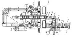
- FIG. 1is a simplified top plan view of an assembly line according to the present invention
- FIG. 2is an end perspective view of a handling and transfer station according to the invention, which is a part of the assembly line of FIG. 1;
- FIG. 3is a birds-eye perspective view of the handling and transfer station of FIG. 2;
- FIG. 4is a simplified side view of part of a gripper apparatus, which is a component shown in FIGS. 2-3, showing a juxtaposed progressive time-lapse sequence of positions of the opposed jaws thereof, during full travel from open to closed;
- FIG. 5Bis a top plan view of a gripper apparatus of FIGS. 2-3;
- FIG. 6is an exploded perspective view of the gripper apparatus of FIGS. 2-5, showing component parts thereof;
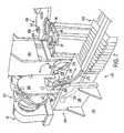
- FIG. 7is a perspective view of an end cap application station, which is also part of the assembly line of FIG. 1, and also showing an inductive heating apparatus;
- FIG. 8is a perspective view of an unloading station, which is another part of the assembly line of FIG. 1;
- FIG. 9is a side plan view of the unloading station of FIG. 8.
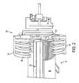
- FIG. 10is a side plan view of an adhesive dispensing apparatus
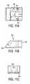
- FIG. 11Ais a top plan view of a nozzle according to the invention which is usable with the dispensing apparatus of FIG. 10, showing internal passages in phantom;
- FIG. 11Bis a side plan view of the nozzle of FIG. 11A;
- FIG. 11Cis an end plan view of the nozzle of FIG. 11A;
- FIG. 11Dis a diagram showing origin of the aperture of the nozzle in FIGS. 11A-11C;
- FIG. 12Ais a side plan view of an emplacement applicator assembly which is part of the end cap application station of FIG. 7, showing the orientation thereof at a first time;
- FIG. 12Bis a side plan view similar to FIG. 12A, showing the orientation of the emplacement applicator at a second time, subsequent to that of FIG. 12A;
- FIG. 12Cis a bottom plan view of the emplacement applicator assembly of FIGS. 12A-12B;
- FIG. 12Dis a top plan view of an annular clamping jig which is part of the emplacement applicator assembly of FIGS. 12A-12C;
- FIG. 12Eis a top plan view of a hollow end cap which fits into the clamping jig of FIG. 12D;
- FIG. 13is a side plan view of the application station of FIG. 7, showing a juxtaposed progressive time-lapse sequence of positions of the two opposed end cap emplacement applicators;
- FIG. 14Ais a side plan view of an end cap pre-cure station which is another portion of the assembly line of FIG. 1;
- FIG. 14Bis a top plan view of the end cap pre-cure station of FIG. 14A;
- FIG. 14Cis an inner end plan view of the end cap pre-cure station of FIG. 14A;
- FIG. 15is a side plan view of the unloading station of FIGS. 8-9.
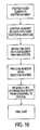
- FIG. 16is a series of method steps in a method of making a filter cartridge according to the present invention.
- FIG. 1an overview of an assembly line is shown generally at 10 in FIG. 1, from an overhead birds-eye vantage point.
- the assembly line of FIG. 1operates according to a process involving a number of sequentially performed steps.
- the assembly line 10 depicted in the drawingis provided for assembling fluid filter cartridges 17 (FIG. 8 ).
- the filter cartridges 17are, in turn, used as components in manufacturing spin-on oil filter assemblies, during which the cartridges are encased in hollow housings.
- Each filter cartridge 17includes a porous filter element 20 (FIG. 2) having a center tube 22 therein, and two metal end caps 93 , 94 , which are affixed to opposite ends of the filter element with a plastisol adhesive.
- a first end cap 93(FIG. 12E) has a hollow opening 95 formed centrally therethrough, and a second end cap 94 (FIG. 7) is closed at the central area thereof.
- a series of spindles 12may be seen at the lower right quadrant of FIG. 1 .
- Each spindle 12has an associated trough 14 for supporting a cylindrical filter element 20 from below.
- the filter elements 20are intentionally omitted from FIG. 1 for purposes of simplifying the illustration, but a filter element is shown in FIGS. 2 - 3 ).
- the spindle 12 and trough 14move together as an assembly 15 on a continuous-loop feed conveyor 11 .
- each filter element 20is made substantially in the shape of a hollow cylinder, and is associated with a foraminous center tube 22 for reinforcing placement in the center thereof.
- the spindle/trough assembly 15moves laterally on the feed conveyor 11 , and transports the filter element 20 over towards a gripper assembly 30 , which is initially in an open configuration to receive the filter element.
- the gripper assembly 30provides a handling and transfer apparatus for a cylindrical workpiece, such as the filter element 20 .
- the gripper assembly 30is temporarily held in the open configuration thereof by pressure from an actuator 92 on a cam follower bearing 88 (FIG. 3 ).
- a paddle arm 16pushes the filter element 20 , and associated center tube 22 , out of the trough 14 , through a half-pipe guide sleeve 19 , and into an upwardly curving lower jaw 34 of the gripper assembly 30 .
- a computer-controlled servo motor 25activates the paddle arm 16 to push the filter element 20 a measured distance forward, which moves it through the guide sleeve 19 and into the gripper assembly lower jaw 34 , so as to center the element therein.
- An adjustable stop member 50may, optionally, also be provided, to limit the distance that the filter element 20 can travel forward from the guide sleeve 19 .
- the paddle arm servomay be programmed to push a different stroke distance, for a different-sized filter element, at the push of a button.
- the opposed jaws 32 , 34 of the gripper assembly 30are curved in opposite directions and define a cylindrical space therebetween when closed, to closely conform to the tubular shape of the filter element 20 .
- Each of the jaws 32 , 34includes a plurality of spaced-apart teeth 36 , as shown, which mesh together when the jaws are closed, and which allow the jaws to interlock with one another, as they close around a filter element 20 .
- the outermost tips of the teeth 36are tapered to help align a filter element 20 therebetween.
- the teeth 36mesh together to form a continuous reference surface while the unconstrained workpiece is grasped thereby.
- the intermeshing of the teeth 36allows the jaws 32 , 34 to constrain a previously un-constrained cylindrical workpiece to a matching cylindrical reference surface formed by the meshing of the two jaws.
- the tapered shape of the outermost tips of the teeth 36help to correctly orient the cylindrical filter element 20 between the jaws 32 , 34 without appreciable risk of pinching or damaging the element during orientation thereof.
- each of the individual jaws 32 , 34may be made as a subassembly, and may be separated into component parts, i.e., a hinge portion and a jaw extension.
- the respective extensions 35 , 37include the teeth 36 , and the extensions are quickly releasable and interchangeable from their respective hinge portions 38 , 40 , to allow a user to remove the extensions and substitute replacement extensions (not shown) of a different size. This permits rapid line change-over to fit another size of filter being assembled, as appropriate.
- the gripper assembly 30is capable of accurately and repeatably holding any diameter workpiece to within 0.002 inches relative to the fixed center point shown in FIG. 5 A.
- the center pointremains at the center of the jaw extensions 35 , 37 , regardless of what size jaw extensions are used. This constant center point facilitates adjusting the apparatus for a different sized filter when the jaw extensions are changed.
- the fixed center pointeliminates the need for any height changeover for the emplacement applicators and the inductive heaters, other than servo length setting, or for any adjustment to the unloader. These additional components will be explained at a later point herein.
- the gripper assembly 30is one of a series of interconnected gripper assemblies which are substantially identical to one another.
- the multiple gripper assemblies 30are mounted on a transport conveyor 33 (FIGS. 1, 9 ).
- the transport conveyor 33is a chain loop conveyor that continuously cycles around, with pauses at the individual work stations.
- the opposed jaws 32 , 34 of an individual gripper assembly 30will be in a first horizontal orientation thereof, as shown in FIGS. 2, 3 , and 5 during the initial pick-up of a workpiece, but will then rotate 90 degrees, to the vertical orientation shown in FIG. 7, with the tips of the extensions pointing upward, as the gripper assembly moves along. Later in the assembly process, the gripper assembly 30 will again rotate 90 degrees to a second horizontal orientation thereof, for transferring the workpiece to a drop-off station 100 , as shown in FIGS. 8-9. After drop-off, each of the closed gripper assemblies 30 will cycle back along the underside of the transport conveyor 33 , to the point where it receives a new filter element 20 from the feed conveyor 11 , to begin the cycle again. Three of the above-described primary orientations of the gripper assembly 30 may be seen in FIG. 9 .
- the gripper assembly 30includes the upper and lower jaws 32 , 34 as noted, and each of the upper and lower jaws is separable into a hinge portion and an extension, as outlined above.
- the gripper assembly 30also includes an inner cage 46 , a spring 48 , an outer cage 52 , and a pivot pin 54 . Each of these components of the gripper assembly 30 will be discussed in further detail herein.
- the jaws 32 , 34each include a plurality of spaced apart teeth 36 , as noted, and each of the jaw hinge portions 38 , 40 includes a plurality of spaced apart flanges 56 .
- each of the jaw hinge portions 38 , 40has a cylindrical actuator shaft 58 , 60 , respectively, extending outwardly thereon.
- the cylindrical actuator shafts 58 , 60each carry a bearing 62 , 63 , respectively, rotatably mounted thereon.
- the respective shaft and bearing combinations 58 , 62 and 60 , 63are provided as integral cam follower bearing assemblies.
- a second set of actuator shafts and bearing assemblieswhich are identical to those shown in the drawing, may be provided on the parallel opposite side surfaces of the hinge portions 38 , 40 .
- a single setis sufficient.
- Each of the jaw hinge portions 38 , 40also has a hollow bore 64 , 66 , respectively, formed through the flanges 56 , for receiving the pivot pin 54 therein, when the flanges are intermeshed with one another and placed within the inner cage 46 .
- the jaw extension 35has alignment studs 42 (FIG. 3) attached to and extending away from the innermost face thereof, and these alignment studs include enlarged heads, as shown.
- the alignment studs 42may be inserted into wide portions of key slots 44 (FIG. 6) of the hinge portion 38 , and then the extension 35 can then be slidably moved with respect to the hinge portion, in the direction of the key slots 44 , to lock the hinge portion and extension together in an aligned configuration.
- the lower extension 37is attached to the lower hinge portion 40 in similar fashion.
- the jaw extensions 35 , 37are slid until they will not move any further, at which point a respective spring-loaded detent button 45 , 47 , attached to the cover plate, as shown, fits engagingly into a corresponding hollow cylindrical cavity (not shown) appropriately formed in the inward-facing surfaces of the jaw extensions.
- the hinge portions 38 , 40are provided with appropriate conventional hardware to allow an operator to selectively release the detent buttons 45 , 47 when the operator wishes to detach the jaw extensions 35 , 37 from the hinge portions.
- the inner cage 46provides a housing for the jaws 32 , 34 , and with the respective flanges 56 of the jaw hinge portions 38 , 40 intermeshed with one another, the jaws 32 , 34 fit together inside of the inner cage 46 .
- the inner cage 46has a generally box-like shape, which is open at two sides and an end thereof, as shown.
- the inner cage 46includes two opposed side walls 68 , 70 connected to a backing plate 72 , substantially at right angles thereto. As viewed from above, in the orientation shown in FIG. 6, the inner cage 46 has a substantially U-shaped outline.
- the space between the side walls 68 , 70 , on each side of the inner cage 46is preferably left open, to allow outward movement of the jaw extensions 35 , 37 without any interference or resistance by the inner cage structure.
- both of the side walls 68 , 70may be provided with the structure and reinforcing bars shown on the near side wall 70 in FIG. 6 . Otherwise, the inclusion of such structure on only one side wall 70 is sufficient.
- each of the two opposed side walls 68 , 70 of the inner cage 46has a reinforced edge portion at the top thereof, as shown, and these reinforced edge portions have hollow bores 69 , 71 formed respectively therethrough.
- the inner cageincludes a solid backing plate 72 , which interconnects the side walls 68 , 70 .
- the backing plate 72has a circular groove 74 inscribed therein, to provide a first seat for the spring 48 .
- the side edges of the inner cage side walls 68 , 70have track extensions 75 (FIGS. 5A, 5 B) attached thereto, to guide sliding movement of the outer cage 52 thereon.
- the outer cage 52includes a generally rectangular frame 76 , formed of four flattened frame sections connected to one another.
- the outer cage 52is provided with four micro-linear bearings 55 (FIG. 5B) attached thereto with conventional fasteners.
- the micro-linear bearings 55are provided to roll along the tracks 75 of the inner cage, to smooth out and facilitate sliding movement of the outer cage 52 along the inner cage 46 .
- one frame section 80 of the outer cage 52has a pair of linearly spaced apart guide slots 82 , 84 formed therethrough.
- the frame section 80has a post 86 affixed thereto, and extending outwardly thereon.
- this post 86has a cam follower bearing 88 (FIG. 3) rotatably attached thereto.
- the post 86 and bearing 88are provided together as a cam follower bearing assembly.
- the side of the outer cage 52 opposite the frame section 80may also have guide slots formed therein which mirror the guide slots 82 , 84 of the frame section 80 .
- a single pair of guide slotsis sufficient.
- a central crossmember 78bridges across, and is removably attached to, two of the sections making up the frame 76 .
- the central crossmember 78has a circular groove 79 inscribed in the surface thereof, which faces toward the backing plate 72 , to provide a second seat for the spring 48 .
- the crossmember 78is lined up between, and oriented parallel to the side walls 68 , 70 of the inner cage 46 , as shown.
- the outer cageis then placed over the inner cage, with the side walls 68 , 70 inside of the frame 76 , to slidably interconnect the inner and outer frames, with the spring 48 extending between the crossmember and the inner cage backing plate 72 .
- the jaw hinge portions 38 , 40are then placed into the outer cage 52 , with the flanges 56 aligned and intermeshed with one another, and with the bearings 62 , 63 installed in the guide slots 82 , 84 of the outer cage frame section 80 , as seen in FIG. 5 A.
- the jaw extensionsare then connected to their corresponding hinge portions, as previously described.
- the pivot pin 54is inserted through, and is anchored in the hollow bores 69 , 71 of the inner cage side walls 68 , 70 , to pivotally attach each of the jaws 32 , 34 to the inner cage 42 .
- the actuator posts 58 , 60extend outwardly from the inner cage, between the bars thereof, and the bearings 62 , 63 fit slidably inside of the guide slots 82 , 84 of the outer cage.
- the actuator 92releases its pressure on the cam follower bearing 88 , which is connected by the post 86 to the outer cage 52 .
- This movement of the actuator 92releases the force which has been compressing the spring 48 in the inner cage 46 .
- the outward pressure of the spring 48pushes the outer cage 52 away from the base plate 72 , and moves the outer cage relative to the inner cage.
- the outward movement of the outer cageputs pressure on the shafts 58 , 60 of the jaw hinge sections, via the bearings 62 , 63 .
- This designhas the advantage of being able to continue to accurately hold a workpiece even in the event of a power interruption, because of the relatively unencumbered construction and arrangement of the gripper assembly 30 . No external power source is required for the gripper assembly 30 to continue to securely and accurately hold a workpiece therein, once the workpiece has been picked up. The force of the spring 48 will continue to urge the jaws 32 , 34 closed, until a countervailing force is applied to overcome the spring force.
- the gripper assembly 30then moves the filter element, via the transport conveyor 33 , to an end cap mounting station, shown in FIG. 7, where two end caps are simultaneously placed on opposite ends of the filter element. This simultaneous placement is illustrated in FIG. 13 .
- the first end cap 93looks substantially similar to the second end cap in the drawing, with the exception that the central portion of the first end cap has a hollow aperture 95 (FIG. 12E) formed through the center portion thereof, which is necessary for the proper functioning of the filter cartridge assembly 17 . It will therefore be understood that the following description of the second end cap 94 also applies to the first end cap 93 , with the single difference that the first end cap 93 has a centrally located hollow aperture 95 therein, radially internally of the inner edge portion thereof.
- each end cap 93 , 94has a circular outline as seen in the top plan view of FIG. 8, and includes a flattened O-shaped base 96 and inner and outer side walls 97 , 98 integrally formed with the base and extending outwardly therefrom and substantially transverse thereto. Together, the base 96 and edge portions 97 , 98 form an annular tray, and define a hollow receptacle 99 therebetween for holding a measured amount of adhesive, and for receiving a peripheral end of the filter element 20 therein.
- an operatorloads individual end caps into a belt-driven feeder conveyor 23 (FIG. 1 ), which sequentially transfers the end caps to a rotary indexer 200 .
- the belt-driven feeder conveyoruses two parallel continuous-loop belts, running on two pairs of spaced-apart pulleys, to move the end caps in the desired direction.
- end cap feed lines 27 , 29are provided for each type of end cap 93 , 94 .
- the end capsare mechanically placed in sequence on the feeder conveyors 23 , with the end cap openings 99 facing up.
- end caps 93 , 94are moving along their respective conveyors 23 , and then are transferred to their respective emplacement applicators, at the same time that the filter element is being picked up by the gripper assembly and transferred to the application station.
- the adhesive-filled end caps and filter elementmeet at the application station, as will be further described.
- the end capsmove on the conveyor to a rotating circular dial plate 202 of a rotary indexer 200 , where they are filled with uncured plastisol resin (not shown).
- the rotary indexer 200has four identical openings 204 formed in the dial plate 202 thereof, and only three of these openings are used at any given time in the assembly process.
- the feed conveyor 23feeds an end cap 93 to the dial plate 202 for initial pickup.
- the opening 204 of the dial plate 202is provided with a ledge 206 for supporting placement of an end cap thereon, and the feeder conveyor 23 feeds an end cap into the opening and on top of the ledge.
- the dial plate 202then rotates 90 degrees through a horizontal plane, to move the end cap to a fill station 210 (FIG. 10 ).
- a linear actuatortemporarily lifts the end cap off of the dial plate 202 .
- a dispenser 211is selectively fed measured batches of plastisol adhesive, under controlled pressure conditions, through an adhesive flow circuit. Flow of the adhesive is precisely controlled by enabling and disabling an electrically controlled solenoid valve.
- the end capis lifted from the dial plate by a linear actuator, having a rotatable turntable thereon. Adhesive flow is initiated when the end cap reaches the level of a dispensing nozzle 212 .
- a dispensing nozzle 212precisely dispenses the needed amount of plastisol therein. After one full rotation, flow through the nozzle 212 is stopped, and the linear actuator then retracts and replaces the end cap in the opening of the dial plate 202 .
- the dispensing nozzle 212is formed having an outlet formed as a substantially trapezoidal aperture 130 therein, to correctly distribute the material in a graduated and increasing fashion, from the inside diameter of the end cap out to the outside diameter thereof.
- the diameter of the nozzle aperture 130is based on a wedge-shaped section cut out of a ring shape, using substantially radial straight lines, intersecting the ring to define the top and bottom sides of the wedge.
- Nozzle aperture widthis chosen to correspond to the width of the end cap recess 99 for a particular filter cartridge, and three different examples of nozzle aperture widths are shown in FIG. 11 .
- the wedge shape of the nozzle apertureis calculated to be proportional to the circumferences of the inside and outside diameters of the end cap. This compensation is necessary, because more material is needed around the end cap outside diameter than is needed around the inside diameter, due to the greater distance around the outside diameter. This relationship is shown in FIG. 11 .
- the ratio of the nozzle aperture width at the outside diameter to the nozzle aperture width at the inside diameteris ( ⁇ )(outside diameter) divided by ( ⁇ )(inside diameter) equals (O.D./I.D.)
- the relationshipis linear between these points, so the gap simply narrows uniformly from the O.D. to the I.D.
- the nozzle 212is formed as a hollow body 132 from a hollowed-out piece of material, which is preferably a metal.
- the nozzle 212has a flow passage formed therethrough, including a cylindrical bore 134 formed therein defining an inlet 136 .
- the flow passageenters an end surface of the nozzle body 132 via the bore 134 , continues inwardly until it is about halfway through the body, and then makes a substantially right-angle turn, as shown.
- the flow passagecommunicates with a substantially flattened channel 140 formed in the outlet end of the nozzle body.
- the flattened channel 140has a wedge-shaped cross section corresponding to the nozzle aperture 130 .
- a pair of mounting holes 142 , 144may be formed through the body 132 of the nozzle, but the mounting holes are not required.
- the nozzle inletis formed as a hollow cylinder, having female threads formed therein, to allow the nozzle to be threadably and rotatably attached to the dispenser.
- the tip of the nozzleis tapered, as shown, and the nozzle has a substantially flattened end face formed in the tip thereof, with the outlet aperture formed in the substantially flattened end face.
- the substantially flattened end faceis disposed at an angle with respect to an adjoining surface of the nozzle, to facilitate and direct fluid flow therefrom.
- the dial platespins another 90 degrees, and a ‘walking beam’ then picks up the filled end cap from the rotary indexer and places the end cap in a holding fixture, shown supporting the end cap 94 in FIG. 7 .
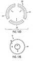
- the adhesiveis allowed to stabilize in the holding fixture for one quarter rotation of the dial plate 202 , after which, the filled end cap is placed into a substantially annular constrictable clamping jig 222 , of an emplacement applicator assembly 220 .
- the substantially annular clamping jig 222(FIG. 9) includes a cylindrical body attached to the applicator plate, and a circular collar which is movably mounted on the cylindrical body.
- the circular collaris made up of three individual arcuate segments 224 , 226 , 228 , respectively, which are movably attached to the cylindrical base.
- Each of the arcuate segments 224 , 226 , 228can be reciprocally and radially moved, with respect to the center point of the clamping jig, in the direction of the two-headed arrows shown in FIG. 12 D.
- Each segment of the clamping jigis substantially identical to the other segments, and when moved close together into edge-to edge contact with one another, the three segments 224 , 226 , 228 define a circular hollow therebetwen for holding an end cap 93 therein.
- the circular collarincludes an inwardly tapered inner edge 225 , for compressively forcing the peripheral outermost edge of the filter element inwardly as the collar moves therepast.
- the tapered inner edge 225is provided to ensure that the entire circumference of the peripheral edge fits within the hollow end cap receptacle, inside the outer side edge of the end cap.
- the end cap application station 230includes a stationary support base 232 , and a guide member 234 which is fixedly attached to the stationary support base.
- the guide member 234includes a pair of parallel opposed, substantially vertical first and second guide plates 236 , 238 , respectively.
- Each of the guide plates 236 , 238has a respective guide groove 239 , 240 formed therein.
- the guide grooves 239 , 240face inwardly towards one another, and are substantially similar in shape and size.
- Each of the guide grooves 239 , 240defines a ramp, such as that shown at 242 , therein.
- the guide groove 240is formed in a stretched-out forward or reverse “S” shape, as shown.
- This preferred guide groove constructionincludes a substantially horizontal first section 244 at its lowermost part; a second section 245 , which is disposed at an angle with respect to the first section, and which defines the ramp 242 at the bottom surface thereof; and a substantially horizontal third section 246 at the top part of the groove.
- the guide groovesproduce both the linear and rotary motion of the emplacement applicator assembly 220 using only one axis of movement.
- the elongated upper horizontal third section 246 of the guide grooveaccommodates varying filter sizes, without requiring a mechanical changeover of the guide member 234 . This is greatly simplified from the previously known assemblies for providing a combined linear and rotary motion.
- a push bar 250is situated above the support base 232 of the application station 230 , and the push bar is linearly and reciprocally slidable with respect to the stationary support base.
- a servo motor 252is provided to power sliding movement of the push bar 250 .
- the push bar 250has a drive plate 254 affixed thereon, at the top thereof.
- the drive plate 254has an integrally attached spacer 256 affixed thereto and extending upwardly thereon, and the spacer has an axle shaft 257 passing horizontally therethrough, to provide a pivot connection between the drive plate and a back plate 260 of an emplacement applicator 220 , as will be further described below.
- an emplacement applicator 220is provided for placing an end cap 94 on an end of the filter element 20 .
- an emplacement applicatoris provided for each end cap 93 , 94 .
- the drive plate 254may be viewed as part of the emplacement applicator 220 .
- the emplacement applicator 220includes a back plate 260 which is pivotally attached to the drive plate 254 via the axle shaft 257 , by virtue of a hollow passage formed through appropriate sections thereof.
- the back plate 260may be pivotally moved from a flat position to an upright vertical position as shown in FIG. 12, for purposes of convenience, the back plate will be described in the upright orientation thereof shown in FIG. 7 . It will be understood that the relative descriptive terms for the different parts of the back plate 260 are used to illustrate, rather than to limit the invention.
- the back plate 260has an upper part 262 shaped like a capital letter “D” turned to rest on its flat edge, and a lower part which is operatively pivotally attached to the drive plate 254 at a pivot connection 255 .
- the lower part of the back plate 260consists of two legs 264 , 266 which are integral with the upper part 262 and which extend downwardly therefrom on opposite sides thereof.
- Each of the legs 264 , 266has a transverse flange 268 , 270 , attached thereto and extending forwardly thereon, and the front part of each flange has a cylindrical bore formed therein, which receives the axle shaft 257 therethrough, to pivotally mount the back plate 260 to the upper end of the drive plate spacer 256 .
- each of the legs 264 , 266has a respective cam follower bearing assembly 265 , 267 attached to an inner edge portion of the transverse spacer 256 , which is spaced away from the pivot connection 255 and from the axle shaft 257 .
- the races of the cam follower bearing assemblies 265 , 267are disposed resting on the ramps of the respective guide members, as shown in FIG. 7 .
- the above-described arrangement of the emplacement applicator 220allows it to reliably and reproducibly emplace an end cap 94 on the end of a filter element 20 with a great degree of precision, reliability and reproducibility so as to provide a more standardized filter cartridge assembly than was heretofore possible.
- FIG. 13illustrates various positions of the two opposed emplacement applicators 219 , 220 , as they move toward simultaneously emplacing the end caps 93 , 94 on the filter element 20 . Intermediate positions of the applicators are shown in phantom. The end caps 93 , 94 are omitted from FIG. 13 for purposes of simplifying the illustration.
- the end cap clamping jig 222is activated to move the segments radially outwardly, to release the end caps therefrom.
- the opposed push barsare then retracted, by activating two synchronized servo motors, connected to threaded shafts which pass through the push bars, to move the emplacement applicators 219 , 220 back to the horizontal orientation thereof, where they can pick up the next two end caps 93 , 94 .
- the transport conveyor 33advances the gripper assembly 30 to a pre-cure station 280 (FIG. 14 ), where it is placed between two inductive heating assemblies 282 , 284 , which incorporate electromagnetic field (EMF) generators.
- EMFelectromagnetic field
- Inductive heating assembliesare relatively well known and are commercially available; however, it is applicant's understanding that inductive heaters have not been used in connection with a filter cartridge assembly apparatus and method.
- the inductive heating assemblies 282 , 284are respectively mounted on opposite ends of a double ball screw 286 for simultaneous motion in opposite directions, and they move into close proximity to the end caps.
- the double ball screw 286is operated by a servo motor 288 .
- the double ball screwincludes a shaft which is rotatably mounted in a support structure. A first end of the shaft is threaded in a first direction, such as with a standard right-hand thread, while the opposite end of the shaft is threaded in a second direction which is the opposite of the first direction.
- Matching female threadsare provided inside each of the heating assemblies 282 , 284 corresponding to the part of the shaft that the heating assembly is mounted on. In this way, spinning the shaft, in a single direction of rotation, causes the heating assemblies 282 , 284 to move in opposite directions.
- Each of the inductive heating assemblies 282 , 284then generates a high-frequency electromagnetic field surrounding its respective associated end cap 93 , 94 .
- the electromagnetic fieldinduces current flow within the metal of the end cap, thereby generating heat and rapidly heating the end cap to partially cure the plastisol resin therein, sufficiently to form a bond between the end cap and the filter element 20 , and to fix the position of the end cap with respect to the filter element.
- the inductive heating assemblies 282 , 284do not themselves become hot, which has two distinct advantages, as compared to a conventional heating element, in the method according to the present invention.
- This pre-cure stepis important for several reasons. It fixes the position of the end caps 93 , 94 with respect to the paper element 20 , and this relative positioning carries through to the finished product.
- the pre-curestops flow movement of uncured plastisol within the end caps, ensuring good end seals around the filter element. This increases efficiency and reduces scrap.
- the short duration of the pre-cureallows for increased productivity and higher filter production volumes in a given time period.
- the gripper assembly 30carries the pre-cured filter cartridge assembly down to a dropoff point, where the gripper assembly is opened to drop the filter into a transfer mechanism, for transferring the filter to a cure line.
- the individual gripper assembly 30carries the filter element down to a drop-off station 100 , shown in FIG. 8, where the gripper assembly 30 is opened to drop the workpiece.
- a drop-off station 100shown in FIG. 8, where the gripper assembly 30 is opened to drop the workpiece.
- the transport conveyor 33moving the gripper assembly 30 past a stationary cam 85 , which is attached to a plate 87 , as shown in phantom in FIG. 8 .
- the stationary campresses on the cam follower bearing 88 of the gripper assembly 30 .
- This pressuremoves the outer cage 52 inwardly towards the base plate of the inner cage, which presses the crossmember 78 so as to compress the internal spring 48 of the assembly.
- the shuttle memberhas two opposed Y-shaped cradles 104 , 106 , which are each pivotally attached to opposite ends of a yoke 105 .
- the Y-shaped cradles 104 , 106pivot sideways together, in coordinated fashion, to transfer the filter cartridge 17 into a covered tray 110 .
- the covered tray 110is pivotally movable through a 90-degree arc, from a horizontal orientation, shown in solid lines, to a vertical orientation thereof, shown in phantom in FIG. 15 .
- the covered trayis movable in this way, for purposes of convenience, it will be initially described in the horizontal orientation thereof shown in FIG. 8, with the understanding that it may be moved from that orientation.
- the covered tray 110includes a base tray portion 112 , having a substantially V-shaped cross-section, and with a slot formed in the center thereof where the sides of the base tray portion come together.
- the slotextends about half the length of the base tray portion 112 .
- a first end of the base tray portion 112is pivotally attached to a fixed support frame 114 via a pivot connection 121 , to allow for pivotal movement of the covered tray relative to the support frame.
- a second end of the base membercarries an integrally attached backstop 116 of the covered tray, which extends upwardly from the base tray, as shown.
- a cover plate 118extends outwardly therefrom from the backstop 116 above the base tray portion 112 , to provide reinforcing support to the filter cartridge 17 , as it is rotated from a vertical orientation to a horizontal orientation thereof.
- An extendable piston member 120extends between the fixed support frame 114 and the underside of the base tray portion 112 , where the piston member is attached with a pivotally movable connection. It will be understood that when the piston member 120 is extended, it forces the covered tray 110 to rotate 90 degrees around the pivoting connection 121 , to the position shown in phantom in FIG. 15 . This allows the filter cartridge 17 to fall out of the covered tray, in a vertical orientation thereof, on to a conveyor belt which conveys the cartridge to a final cure oven, where the adhesive is baked to permanently fix the end caps 93 , 94 in place on the filter element 20 .
Landscapes
- Chemical & Material Sciences (AREA)
- Chemical Kinetics & Catalysis (AREA)
- Physics & Mathematics (AREA)
- Geometry (AREA)
- Filtering Materials (AREA)
- Filtration Of Liquid (AREA)
- Filtering Of Dispersed Particles In Gases (AREA)
Abstract
Description
Claims (12)
Priority Applications (2)
| Application Number | Priority Date | Filing Date | Title |
|---|---|---|---|
| US10/037,608US6817466B2 (en) | 2000-11-09 | 2001-11-07 | Apparatus for manufacturing filter cartridges, and method of using same |
| US10/979,618US7255760B2 (en) | 2000-11-09 | 2004-11-01 | Apparatus for manufacturing filter cartridges, and method of using same |
Applications Claiming Priority (2)
| Application Number | Priority Date | Filing Date | Title |
|---|---|---|---|
| US24745000P | 2000-11-09 | 2000-11-09 | |
| US10/037,608US6817466B2 (en) | 2000-11-09 | 2001-11-07 | Apparatus for manufacturing filter cartridges, and method of using same |
Related Child Applications (1)
| Application Number | Title | Priority Date | Filing Date |
|---|---|---|---|
| US10/979,618ContinuationUS7255760B2 (en) | 2000-11-09 | 2004-11-01 | Apparatus for manufacturing filter cartridges, and method of using same |
Publications (2)
| Publication Number | Publication Date |
|---|---|
| US20020124937A1 US20020124937A1 (en) | 2002-09-12 |
| US6817466B2true US6817466B2 (en) | 2004-11-16 |
Family
ID=22934989
Family Applications (2)
| Application Number | Title | Priority Date | Filing Date |
|---|---|---|---|
| US10/037,608Expired - LifetimeUS6817466B2 (en) | 2000-11-09 | 2001-11-07 | Apparatus for manufacturing filter cartridges, and method of using same |
| US10/979,618Expired - LifetimeUS7255760B2 (en) | 2000-11-09 | 2004-11-01 | Apparatus for manufacturing filter cartridges, and method of using same |
Family Applications After (1)
| Application Number | Title | Priority Date | Filing Date |
|---|---|---|---|
| US10/979,618Expired - LifetimeUS7255760B2 (en) | 2000-11-09 | 2004-11-01 | Apparatus for manufacturing filter cartridges, and method of using same |
Country Status (7)
| Country | Link |
|---|---|
| US (2) | US6817466B2 (en) |
| EP (1) | EP1337303B1 (en) |
| JP (1) | JP2004516926A (en) |
| AT (1) | ATE291477T1 (en) |
| BR (1) | BR0115255A (en) |
| DE (1) | DE60109639T2 (en) |
| WO (1) | WO2002038243A2 (en) |
Cited By (2)
| Publication number | Priority date | Publication date | Assignee | Title |
|---|---|---|---|---|
| US20060169749A1 (en)* | 2005-02-02 | 2006-08-03 | Tvi Corporation | Method for manufacturing filter canisters and tracking quality assurance |
| US11260541B2 (en)* | 2019-03-01 | 2022-03-01 | Gimatic S.R.L | Gripper for industrial manipulators |
Families Citing this family (7)
| Publication number | Priority date | Publication date | Assignee | Title |
|---|---|---|---|---|
| JP4392052B2 (en) | 2008-03-26 | 2009-12-24 | 国立大学法人広島大学 | LIGHT EMITTING ELEMENT AND MANUFACTURING METHOD THEREOF |
| EP2525891B1 (en) | 2010-01-22 | 2020-10-07 | Donaldson Company, Inc. | Pulse jet air cleaner systems; evacution valve arrangements; air cleaner components; and, methods |
| TW201132487A (en)* | 2010-03-29 | 2011-10-01 | Yu Yang Co Ltd | Method of manufacturing filter cartridge and cartridge base with controlled true roundness |
| BR112015015800A2 (en) | 2013-01-14 | 2017-07-11 | Cummins Filtration Ip Inc | cleanable filter and methods for cleaning filter element and system installed filter |
| US11318400B2 (en)* | 2020-02-24 | 2022-05-03 | Caterpillar Inc. | Top and bottom loaded filter and locking mechanism |
| CN114162596B (en)* | 2021-12-10 | 2023-12-26 | 安徽科菱智能装备有限公司 | Material overlapping prevention mechanism for conical bearing retainer |
| CN120171113B (en)* | 2025-05-22 | 2025-08-19 | 苏州市蓝天过滤器有限公司 | High-efficient folding assembly device of filter paper |
Citations (20)
| Publication number | Priority date | Publication date | Assignee | Title |
|---|---|---|---|---|
| US1433251A (en) | 1920-07-15 | 1922-10-24 | Nat Paper Can Company | Machine for inserting end closures in can bodies |
| US2739916A (en)* | 1953-12-08 | 1956-03-27 | Fram Corp | Method of making filter cartridges |
| US3164506A (en) | 1961-05-04 | 1965-01-05 | Gen Motors Corp | Method of bonding end closures to paper filter elements |
| US3265035A (en)* | 1963-07-31 | 1966-08-09 | Walker Mfg Co | Feeding and coating device |
| US3306794A (en) | 1963-02-12 | 1967-02-28 | Wix Corp | Method of making a filter element |
| US3948712A (en) | 1974-09-30 | 1976-04-06 | Sprinter System Of America, Ltd. | Method and apparatus for producing closed loop accordion pleated filters |
| FR2416041A1 (en) | 1978-02-03 | 1979-08-31 | Guiot Sa Ets | Automatic mfr. of paper-based cartridge filter assemblies - using HF heating for efficient assembly and curing of resin treated components |
| US4569628A (en) | 1983-12-27 | 1986-02-11 | Microdot Inc. | Transfer mechanism |
| WO1986005443A1 (en) | 1985-03-19 | 1986-09-25 | Skandinaviska Apparatindustri Ab Saiap | Plug applicator and auxiliary equipment |
| US4626307A (en) | 1985-12-23 | 1986-12-02 | Caterpillar Inc. | Machine and method for assembling pleated filter material and a hollow core member |
| US4650234A (en) | 1985-10-31 | 1987-03-17 | Blatt L Douglas | Transfer boom assembly for workpieces |
| US4747816A (en) | 1986-04-28 | 1988-05-31 | Nippondenso Co., Ltd. | Apparatus for making a filter from a material for a filter element |
| US4795524A (en) | 1986-02-07 | 1989-01-03 | Nippondenso Co., Ltd. | Apparatus for fixing cap on end of filter element |
| US4802816A (en) | 1985-10-08 | 1989-02-07 | Excellon Industries | Pick and place machine having improved centering jaws |
| US4811834A (en) | 1986-08-08 | 1989-03-14 | Sumitomo Heavy Industries, Ltd. | Mechanical transfer feeder |
| US5028330A (en) | 1989-06-12 | 1991-07-02 | Allied-Signal Inc. | Filter & process for manufacturing filters using material cured by ultraviolet radiation for end caps |
| US5145388A (en) | 1991-05-31 | 1992-09-08 | Amp Incorporated | Enclosure for crossconnect terminal block |
| US5481794A (en) | 1989-06-01 | 1996-01-09 | Sieba Ag | Device for handling objects and method of using same |
| US5698059A (en) | 1992-11-10 | 1997-12-16 | Alliedsignal Inc. | Filter and method for manufacturing filters |
| US6691860B2 (en)* | 2000-11-09 | 2004-02-17 | Honeywell International Inc. | Gripper mechanism for handling a cylindrical workpiece |
Family Cites Families (96)
| Publication number | Priority date | Publication date | Assignee | Title |
|---|---|---|---|---|
| US475073A (en)* | 1892-05-17 | Edwaed c | ||
| US3303794A (en) | 1967-02-14 | Piston return mechanism | ||
| US793489A (en)* | 1903-12-15 | 1905-06-27 | Lewis Caleb Williams | Card-receptacle for duplicate cribbage. |
| US1014219A (en)* | 1909-11-01 | 1912-01-09 | Edward J Smith | Card-shuffler. |
| US1906604A (en) | 1930-12-01 | 1933-05-02 | Owens Illinois Glass Co | Mechanism for handling glassware |
| US2001220A (en)* | 1932-01-06 | 1935-05-14 | Richard C Smith | Card dealing device |
| US2043343A (en)* | 1933-09-29 | 1936-06-09 | Western Electric Co | Card game apparatus |
| US2001918A (en)* | 1935-01-12 | 1935-05-21 | Wilford J Nevius | Card table top |
| US2415997A (en) | 1946-01-12 | 1947-02-18 | John W Eldred | Article handling apparatus |
| US2937739A (en)* | 1954-05-27 | 1960-05-24 | Levy Maurice Moise | Conveyor system |
| US2815895A (en) | 1955-06-17 | 1957-12-10 | Leslie L Reed | Adapter type dispensing cap for glazier's putty containers |
| US2778644A (en)* | 1955-10-03 | 1957-01-22 | James R Stephenson | Card shuffler and dealer |
| US2950005A (en)* | 1956-08-10 | 1960-08-23 | Burroughs Corp | Card sorter |
| US3069035A (en) | 1959-05-15 | 1962-12-18 | Leonard H Schwarz | Article handling apparatus |
| US3238699A (en) | 1960-03-30 | 1966-03-08 | Automotive Dev Inc | Filter cartridges and machine for making the same |
| US3133847A (en) | 1960-12-02 | 1964-05-19 | Tecalemit Ltd | Fluid filters |
| US3235741A (en)* | 1961-04-24 | 1966-02-15 | Invac Corp | Switch |
| US3354012A (en)* | 1964-01-14 | 1967-11-21 | Pall Corp | Process and apparatus for capping filter elements |
| US3312473A (en)* | 1964-03-16 | 1967-04-04 | Willard I Friedman | Card selecting and dealing machine |
| US3330400A (en) | 1966-03-08 | 1967-07-11 | Miehle Goss Dexter Inc | Mechanism for transferring cylindrical articles |
| US3517477A (en) | 1967-10-06 | 1970-06-30 | Molins Machine Co Ltd | Article handling apparatus |
| US3716238A (en)* | 1970-07-13 | 1973-02-13 | B Porter | Method of prearranging playing cards for educational and entertainment purposes |
| US3897954A (en)* | 1974-06-14 | 1975-08-05 | J David Erickson | Automatic card distributor |
| US3981673A (en) | 1974-09-25 | 1976-09-21 | Beloit Corporation | Parison transfer means |
| US3944230A (en)* | 1975-06-23 | 1976-03-16 | Sol Fineman | Card shuffler |
| US3967847A (en) | 1975-09-15 | 1976-07-06 | Anchor Hocking Corporation | Chuck apparatus for glass container coating line |
| US4159581A (en)* | 1977-08-22 | 1979-07-03 | Edward Lichtenberg | Device for instruction in the game of bridge and method of and device for dealing predetermined bridge hands |
| US4368972A (en)* | 1981-04-15 | 1983-01-18 | Xerox Corporation | Very high speed duplicator with finishing function |
| US4385827A (en)* | 1981-04-15 | 1983-05-31 | Xerox Corporation | High speed duplicator with finishing function |
| US4397469A (en)* | 1982-08-02 | 1983-08-09 | Carter Iii Bartus | Method of reducing predictability in card games |
| US4659082A (en)* | 1982-09-13 | 1987-04-21 | Harold Lorber | Monte verde playing card dispenser |
| US4586712A (en)* | 1982-09-14 | 1986-05-06 | Harold Lorber | Automatic shuffling apparatus |
| US4513969A (en)* | 1982-09-20 | 1985-04-30 | American Gaming Industries, Inc. | Automatic card shuffler |
| US4832342A (en)* | 1982-11-01 | 1989-05-23 | Computer Gaming Systems, Inc. | Computerized card shuffling machine |
| US4497488A (en)* | 1982-11-01 | 1985-02-05 | Plevyak Jerome B | Computerized card shuffling machine |
| US4515367A (en)* | 1983-01-14 | 1985-05-07 | Robert Howard | Card shuffler having a random ejector |
| US4566782A (en)* | 1983-12-22 | 1986-01-28 | Xerox Corporation | Very high speed duplicator with finishing function using dual copy set transports |
| US4667959A (en)* | 1985-07-25 | 1987-05-26 | Churkendoose, Incorporated | Apparatus for storing and selecting cards |
| US4651879A (en) | 1986-01-31 | 1987-03-24 | Clayton Durand Mfg. Co., Inc. | Automatic bottle sorting system |
| FR2595259B1 (en)* | 1986-03-06 | 1988-05-06 | Acticiel Sa | APPARATUS FOR READING AND DISTRIBUTING CARDS, PARTICULARLY PLAYING CARDS, AND CARD FOR USE WITH THIS APPARATUS |
| GB8606681D0 (en)* | 1986-03-18 | 1986-04-23 | Xerox Corp | Sorting apparatus |
| GB2192407B (en) | 1986-07-07 | 1990-12-19 | Metal Box Plc | Electro-coating apparatus and method |
| DE3623586A1 (en) | 1986-07-12 | 1988-01-28 | Heller Geb Gmbh Maschf | GRIP DEVICE |
| CA1265394A (en) | 1986-09-19 | 1990-02-06 | James E. Geary, Jr. | Free surface casting method |
| US4900009A (en)* | 1987-04-20 | 1990-02-13 | Canon Kabushiki Kaisha | Sorter |
| US4807884A (en)* | 1987-12-28 | 1989-02-28 | Shuffle Master, Inc. | Card shuffling device |
| US5036631A (en) | 1988-03-09 | 1991-08-06 | Inventec, Inc. | Sand blast nozzle |
| US5382025A (en)* | 1988-04-18 | 1995-01-17 | D & D Gaming Patents, Inc. | Method for playing a poker game |
| USRE37975E1 (en) | 1988-06-27 | 2003-02-04 | The Charles Machine Works, Inc. | Directional boring head with blade assembly |
| USRE37450E1 (en) | 1988-06-27 | 2001-11-20 | The Charles Machine Works, Inc. | Directional multi-blade boring head |
| US5000453A (en)* | 1989-12-21 | 1991-03-19 | Card-Tech, Ltd. | Method and apparatus for automatically shuffling and cutting cards and conveying shuffled cards to a card dispensing shoe while permitting the simultaneous performance of the card dispensing operation |
| GB2252764B (en)* | 1991-02-12 | 1994-11-09 | Fairform Mfg Co Ltd | Card dispenser |
| US5121921A (en)* | 1991-09-23 | 1992-06-16 | Willard Friedman | Card dealing and sorting apparatus and method |
| US5941322A (en) | 1991-10-21 | 1999-08-24 | The Charles Machine Works, Inc. | Directional boring head with blade assembly |
| US5199710A (en)* | 1991-12-27 | 1993-04-06 | Stewart Lamle | Method and apparatus for supplying playing cards at random to the casino table |
| IT228052Y1 (en) | 1992-06-30 | 1998-02-05 | Ave Spa Off | CLIPS WITH MOVABLE JAWS FOR GRIPPING BOTTLES OR SIMILAR, PREFERABLY APPLICABLE ON AUTOMATIC STERILIZING RINSE MACHINES- |
| US5248211A (en) | 1992-09-02 | 1993-09-28 | Holst Arthur C | Windshield cleaner |
| AT401887B (en)* | 1992-10-13 | 1996-12-27 | Casinos Austria Ag | CARD MIXER |
| GB2272843B (en) | 1992-11-11 | 1996-08-14 | Pall Corp | Filter elements |
| US5303921A (en)* | 1992-12-31 | 1994-04-19 | Shuffle Master, Inc. | Jammed shuffle detector |
| US5275411A (en)* | 1993-01-14 | 1994-01-04 | Shuffle Master, Inc. | Pai gow poker machine |
| US5288081A (en)* | 1993-02-25 | 1994-02-22 | Shuffle Master, Inc. | Method of playing a wagering game |
| IT229775Y1 (en) | 1993-04-05 | 1999-02-05 | Univer Spa | MECHANICAL DEVICE FOR PNEUMATIC CONTROL |
| US5390910A (en)* | 1993-05-24 | 1995-02-21 | Xerox Corporation | Modular multifunctional mailbox unit with interchangeable sub-modules |
| US5571560A (en) | 1994-01-12 | 1996-11-05 | Lin; Burn J. | Proximity-dispensing high-throughput low-consumption resist coating device |
| US5431399A (en)* | 1994-02-22 | 1995-07-11 | Mpc Computing, Inc | Card shuffling and dealing apparatus |
| US5676372A (en)* | 1994-04-18 | 1997-10-14 | Casinovations, Inc. | Playing card shuffler |
| US6068258A (en)* | 1994-08-09 | 2000-05-30 | Shuffle Master, Inc. | Method and apparatus for automatically cutting and shuffling playing cards |
| US5695189A (en)* | 1994-08-09 | 1997-12-09 | Shuffle Master, Inc. | Apparatus and method for automatically cutting and shuffling playing cards |
| DE4439502C1 (en)* | 1994-11-08 | 1995-09-14 | Michail Order | Black jack card game practice set=up |
| EP0726216B1 (en) | 1995-02-07 | 1998-09-09 | Hermann Kronseder | Transporting star wheel for vessels |
| US5605334A (en)* | 1995-04-11 | 1997-02-25 | Mccrea, Jr.; Charles H. | Secure multi-site progressive jackpot system for live card games |
| US5707287A (en)* | 1995-04-11 | 1998-01-13 | Mccrea, Jr.; Charles H. | Jackpot system for live card games based upon game play wagering and method therefore |
| US6346044B1 (en)* | 1995-04-11 | 2002-02-12 | Mccrea, Jr. Charles H. | Jackpot system for live card games based upon game play wagering and method therefore |
| US5944310A (en)* | 1995-06-06 | 1999-08-31 | Gaming Products Pty Ltd | Card handling apparatus |
| US5772505A (en)* | 1995-06-29 | 1998-06-30 | Peripheral Dynamics, Inc. | Dual card scanner apparatus and method |
| US5722893A (en)* | 1995-10-17 | 1998-03-03 | Smart Shoes, Inc. | Card dispensing shoe with scanner |
| US6039650A (en)* | 1995-10-17 | 2000-03-21 | Smart Shoes, Inc. | Card dispensing shoe with scanner apparatus, system and method therefor |
| IT1285911B1 (en) | 1996-04-30 | 1998-06-26 | Gd Spa | PRODUCT CONVEYOR DEVICE |
| US5718427A (en)* | 1996-09-30 | 1998-02-17 | Tony A. Cranford | High-capacity automatic playing card shuffler |
| AU4665697A (en) | 1996-10-07 | 1998-05-05 | Steven M. Moilanen | Modular stamped parts transfer gripper |
| US5779546A (en)* | 1997-01-27 | 1998-07-14 | Fm Gaming Electronics L.P. | Automated gaming system and method of automated gaming |
| US6217447B1 (en)* | 1997-01-31 | 2001-04-17 | Dp Stud, Inc. | Method and system for generating displays in relation to the play of baccarat |
| US6676127B2 (en)* | 1997-03-13 | 2004-01-13 | Shuffle Master, Inc. | Collating and sorting apparatus |
| AUPO564097A0 (en)* | 1997-03-13 | 1997-04-10 | Gaming Products Limited | Sorting apparatus |
| CH692778A5 (en) | 1997-05-07 | 2002-10-31 | Komax Holding Ag | Gripper. |
| US6096212A (en) | 1997-06-10 | 2000-08-01 | Usf Filtration And Separations Group, Inc. | Fluid filter and method of making |
| JP3521716B2 (en) | 1997-11-25 | 2004-04-19 | 凸版印刷株式会社 | Coating liquid supply device for spin coating device |
| DE19816239A1 (en) | 1998-04-11 | 1999-10-14 | Krones Ag | Device for introducing and / or discharging containers into or from a treatment room |
| US6254096B1 (en)* | 1998-04-15 | 2001-07-03 | Shuffle Master, Inc. | Device and method for continuously shuffling cards |
| US6149154A (en)* | 1998-04-15 | 2000-11-21 | Shuffle Master Gaming | Device and method for forming hands of randomly arranged cards |
| US6032714A (en) | 1998-05-01 | 2000-03-07 | Fenton; Jay Thomas | Repeatably positionable nozzle assembly |
| US6403908B2 (en)* | 1999-02-19 | 2002-06-11 | Bob Stardust | Automated method and apparatus for playing card sequencing, with optional defect detection |
| US6250632B1 (en)* | 1999-11-23 | 2001-06-26 | James Albrecht | Automatic card sorter |
| US6361044B1 (en)* | 2000-02-23 | 2002-03-26 | Lawrence M. Block | Card dealer for a table game |
| US6852184B2 (en) | 2000-11-09 | 2005-02-08 | Honeywell International, Inc. | Method for fixing the position of an end cap on a filter element, using inductive heating |
- 2001
- 2001-11-07USUS10/037,608patent/US6817466B2/ennot_activeExpired - Lifetime
- 2001-11-08WOPCT/US2001/048109patent/WO2002038243A2/enactiveIP Right Grant
- 2001-11-08EPEP01990157Apatent/EP1337303B1/ennot_activeExpired - Lifetime
- 2001-11-08DEDE60109639Tpatent/DE60109639T2/ennot_activeExpired - Fee Related
- 2001-11-08ATAT01990157Tpatent/ATE291477T1/ennot_activeIP Right Cessation
- 2001-11-08BRBR0115255-6Apatent/BR0115255A/ennot_activeApplication Discontinuation
- 2001-11-08JPJP2002540819Apatent/JP2004516926A/ennot_activeWithdrawn
- 2004
- 2004-11-01USUS10/979,618patent/US7255760B2/ennot_activeExpired - Lifetime
Patent Citations (20)
| Publication number | Priority date | Publication date | Assignee | Title |
|---|---|---|---|---|
| US1433251A (en) | 1920-07-15 | 1922-10-24 | Nat Paper Can Company | Machine for inserting end closures in can bodies |
| US2739916A (en)* | 1953-12-08 | 1956-03-27 | Fram Corp | Method of making filter cartridges |
| US3164506A (en) | 1961-05-04 | 1965-01-05 | Gen Motors Corp | Method of bonding end closures to paper filter elements |
| US3306794A (en) | 1963-02-12 | 1967-02-28 | Wix Corp | Method of making a filter element |
| US3265035A (en)* | 1963-07-31 | 1966-08-09 | Walker Mfg Co | Feeding and coating device |
| US3948712A (en) | 1974-09-30 | 1976-04-06 | Sprinter System Of America, Ltd. | Method and apparatus for producing closed loop accordion pleated filters |
| FR2416041A1 (en) | 1978-02-03 | 1979-08-31 | Guiot Sa Ets | Automatic mfr. of paper-based cartridge filter assemblies - using HF heating for efficient assembly and curing of resin treated components |
| US4569628A (en) | 1983-12-27 | 1986-02-11 | Microdot Inc. | Transfer mechanism |
| WO1986005443A1 (en) | 1985-03-19 | 1986-09-25 | Skandinaviska Apparatindustri Ab Saiap | Plug applicator and auxiliary equipment |
| US4802816A (en) | 1985-10-08 | 1989-02-07 | Excellon Industries | Pick and place machine having improved centering jaws |
| US4650234A (en) | 1985-10-31 | 1987-03-17 | Blatt L Douglas | Transfer boom assembly for workpieces |
| US4626307A (en) | 1985-12-23 | 1986-12-02 | Caterpillar Inc. | Machine and method for assembling pleated filter material and a hollow core member |
| US4795524A (en) | 1986-02-07 | 1989-01-03 | Nippondenso Co., Ltd. | Apparatus for fixing cap on end of filter element |
| US4747816A (en) | 1986-04-28 | 1988-05-31 | Nippondenso Co., Ltd. | Apparatus for making a filter from a material for a filter element |
| US4811834A (en) | 1986-08-08 | 1989-03-14 | Sumitomo Heavy Industries, Ltd. | Mechanical transfer feeder |
| US5481794A (en) | 1989-06-01 | 1996-01-09 | Sieba Ag | Device for handling objects and method of using same |
| US5028330A (en) | 1989-06-12 | 1991-07-02 | Allied-Signal Inc. | Filter & process for manufacturing filters using material cured by ultraviolet radiation for end caps |
| US5145388A (en) | 1991-05-31 | 1992-09-08 | Amp Incorporated | Enclosure for crossconnect terminal block |
| US5698059A (en) | 1992-11-10 | 1997-12-16 | Alliedsignal Inc. | Filter and method for manufacturing filters |
| US6691860B2 (en)* | 2000-11-09 | 2004-02-17 | Honeywell International Inc. | Gripper mechanism for handling a cylindrical workpiece |
Cited By (5)
| Publication number | Priority date | Publication date | Assignee | Title |
|---|---|---|---|---|
| US20060169749A1 (en)* | 2005-02-02 | 2006-08-03 | Tvi Corporation | Method for manufacturing filter canisters and tracking quality assurance |
| US7320205B2 (en) | 2005-02-02 | 2008-01-22 | Tvi Corporation | Method for manufacturing filter canisters and tracking quality assurance |
| US20080215277A1 (en)* | 2005-02-02 | 2008-09-04 | Tvi Corporation | Method for manufacturing filter canisters and tracking quality assurance |
| US7833306B2 (en)* | 2005-02-02 | 2010-11-16 | Immediate Response Technologies | Method for manufacturing filter canisters and tracking quality assurance |
| US11260541B2 (en)* | 2019-03-01 | 2022-03-01 | Gimatic S.R.L | Gripper for industrial manipulators |
Also Published As
| Publication number | Publication date |
|---|---|
| EP1337303B1 (en) | 2005-03-23 |
| DE60109639T2 (en) | 2006-02-09 |
| DE60109639D1 (en) | 2005-04-28 |
| JP2004516926A (en) | 2004-06-10 |
| ATE291477T1 (en) | 2005-04-15 |
| WO2002038243A2 (en) | 2002-05-16 |
| EP1337303A2 (en) | 2003-08-27 |
| BR0115255A (en) | 2004-10-19 |
| US7255760B2 (en) | 2007-08-14 |
| WO2002038243A3 (en) | 2003-03-27 |
| US20020124937A1 (en) | 2002-09-12 |
| US20050061618A1 (en) | 2005-03-24 |
Similar Documents
| Publication | Publication Date | Title |
|---|---|---|
| US6691860B2 (en) | Gripper mechanism for handling a cylindrical workpiece | |
| US6817466B2 (en) | Apparatus for manufacturing filter cartridges, and method of using same | |
| DE69304430T2 (en) | Device for processing disc-shaped recording media | |
| KR100695879B1 (en) | Terminal Automatic Welding Device for Electronic Components | |
| DE69011749T2 (en) | Object conveyor. | |
| US6852184B2 (en) | Method for fixing the position of an end cap on a filter element, using inductive heating | |
| US6799736B2 (en) | Material dispensing apparatus including a nozzle having a wedge-shaped aperture, and method of using same | |
| JPH09267410A (en) | Bead forming machine and linear body winding device | |
| US10875085B2 (en) | Intelligent automatic conical net making machine | |
| CN117102560A (en) | Intelligent assembling and disassembling valve rod key groove positioning machining device | |
| US6547502B1 (en) | Combination plastic spiral forming machine and semi-automatic plastic spiral binding machine | |
| EP0214079A2 (en) | Apparatus and method for storing and feeding tire beads | |
| DE69922709T2 (en) | A disk reproducing apparatus | |
| KR200418898Y1 (en) | Terminal Automatic Welding Device for Electronic Components | |
| DE2953570C2 (en) | Device for turning over properly supplied preforms made of thermoplastic material | |
| DE102005043103B4 (en) | Device for exchanging optical elements in beam paths | |
| CN118989612B (en) | A sensor laser marking device | |
| KR100703602B1 (en) | Hot melt filter paper fusion machine | |
| EP0054890A1 (en) | Workpiece conveyor, particularly for small pieces | |
| DE4204258C5 (en) | Method and device for the electrochemical machining of workpieces | |
| DE3342899A1 (en) | Device for placing components in the form of small plates and/or rods on a belt | |
| DE3921509A1 (en) | Plane lapping machine with automatic loading and unloading - has workpiece carrier ring set eccentric to lapping wheel to provide load and unload sectors | |
| DE2305895C3 (en) | Device for winding disc bobbins for netting machines | |
| DE4207149A1 (en) | Reworking ceramic non-circular items - involves rotatable holder and profile roller with counter-profile to outer contour of item to be processed |
Legal Events
| Date | Code | Title | Description |
|---|---|---|---|
| STCF | Information on status: patent grant | Free format text:PATENTED CASE | |
| FPAY | Fee payment | Year of fee payment:4 | |
| AS | Assignment | Owner name:FRAM GROUP IP LLC, NEW ZEALAND Free format text:ASSIGNMENT OF ASSIGNORS INTEREST;ASSIGNOR:HONEYWELL INTERNATIONAL INC.;REEL/FRAME:026671/0907 Effective date:20110729 | |
| AS | Assignment | Owner name:CREDIT SUISSE AG, AS FIRST LIEN COLLATERAL AGENT, Free format text:SECURITY AGREEMENT;ASSIGNORS:FRAM GROUP IP LLC;PRESTONE PRODUCTS CORPORATION;REEL/FRAME:026732/0670 Effective date:20110729 | |
| AS | Assignment | Owner name:CREDIT SUISSE AG, AS SECOND LIEN COLLATERAL AGENT, Free format text:SECURITY AGREEMENT;ASSIGNORS:FRAM GROUP IP LLC;PRESTONE PRODUCTS CORPORATION;REEL/FRAME:026740/0089 Effective date:20110729 | |
| FPAY | Fee payment | Year of fee payment:8 | |
| FPAY | Fee payment | Year of fee payment:12 | |
| AS | Assignment | Owner name:CREDIT SUISSE AG, CAYMAN ISLANDS BRANCH, AS COLLAT Free format text:SECURITY INTEREST;ASSIGNOR:FRAM GROUP IP LLC;REEL/FRAME:041190/0001 Effective date:20161223 Owner name:FRAM GROUP IP LLC, ILLINOIS Free format text:RELEASE BY SECURED PARTY;ASSIGNOR:CREDIT SUISSE AG, CAYMAN ISLANDS BRANCH, AS COLLATERAL AGENT;REEL/FRAME:041189/0782 Effective date:20161223 Owner name:FRAM GROUP IP LLC, ILLINOIS Free format text:RELEASE BY SECURED PARTY;ASSIGNOR:CREDIT SUISSE AG, CAYMAN ISLANDS BRANCH, AS COLLATERAL AGENT;REEL/FRAME:041189/0938 Effective date:20161223 Owner name:CREDIT SUISSE AG, CAYMAN ISLANDS BRANCH, AS COLLAT Free format text:SECURITY INTEREST;ASSIGNOR:FRAM GROUP IP LLC;REEL/FRAME:041190/0278 Effective date:20161223 | |
| AS | Assignment | Owner name:BMO HARRIS BANK, N.A., AS SUCCESSOR COLLATERAL AGE Free format text:ASSIGNMENT OF ASSIGNORS INTEREST;ASSIGNOR:CREDIT SUISSE AG, CAYMAN ISLANDS BRANCH, AS RESIGNING COLLATERAL AGENT;REEL/FRAME:041739/0040 Effective date:20170216 | |
| AS | Assignment | Owner name:FRAM GROUP IP LLC, OHIO Free format text:RELEASE OF TERM LOAN PATENT SECURITY INTEREST;ASSIGNOR:CREDIT SUISSE AG, CAYMAN ISLANDS BRANCH, AS COLLATERAL AGENT;REEL/FRAME:048455/0869 Effective date:20190226 Owner name:FRAM GROUP IP LLC, OHIO Free format text:RELEASE OF ABL PATENT SECURITY INTEREST;ASSIGNOR:BMO HARRIS BANK N.A., AS COLLATERAL AGENT;REEL/FRAME:048455/0808 Effective date:20190226 Owner name:CREDIT SUISSE AG, CAYMAN ISLANDS BRANCH, AS COLLAT Free format text:SECOND LIEN INTELLECTUAL PROPERTY SECURITY AGREEMENT;ASSIGNORS:ASC INDUSTRIES, INC.;CARTER FUEL SYSTEMS, LLC;FRAM GROUP IP LLC;AND OTHERS;REEL/FRAME:048887/0495 Effective date:20190226 Owner name:CREDIT SUISSE AG, CAYMAN ISLANDS BRANCH, AS COLLATERAL AGENT, NEW YORK Free format text:SECOND LIEN INTELLECTUAL PROPERTY SECURITY AGREEMENT;ASSIGNORS:ASC INDUSTRIES, INC.;CARTER FUEL SYSTEMS, LLC;FRAM GROUP IP LLC;AND OTHERS;REEL/FRAME:048887/0495 Effective date:20190226 | |
| AS | Assignment | Owner name:BANK OF AMERICA, N.A., AS COLLATERAL AGENT, ILLINO Free format text:ABL INTELLECTUAL PROPERTY SECURITY AGREEMENT;ASSIGNOR:FRAM GROUP IP LLC;REEL/FRAME:048479/0639 Effective date:20190226 Owner name:BANK OF AMERICA, N.A., AS COLLATERAL AGENT, ILLINOIS Free format text:ABL INTELLECTUAL PROPERTY SECURITY AGREEMENT;ASSIGNOR:FRAM GROUP IP LLC;REEL/FRAME:048479/0639 Effective date:20190226 | |
| AS | Assignment | Owner name:ACQUIOM AGENCY SERVICES LLC, MINNESOTA Free format text:SECURITY INTEREST;ASSIGNOR:FRAM GROUP IP LLC;REEL/FRAME:052481/0586 Effective date:20200422 | |
| AS | Assignment | Owner name:STRONGARM, LLC, SOUTH CAROLINA Free format text:RELEASE OF INTELLECTUAL PROPERTY SECURITY INTEREST;ASSIGNOR:ACQUIOM AGENCY SERVICES LLC;REEL/FRAME:053313/0812 Effective date:20200521 Owner name:FRAM GROUP IP LLC, OHIO Free format text:RELEASE OF INTELLECTUAL PROPERTY SECURITY INTEREST;ASSIGNOR:ACQUIOM AGENCY SERVICES LLC;REEL/FRAME:053313/0812 Effective date:20200521 Owner name:TRICO PRODUCTS CORPORATION, MICHIGAN Free format text:RELEASE OF INTELLECTUAL PROPERTY SECURITY INTEREST;ASSIGNOR:ACQUIOM AGENCY SERVICES LLC;REEL/FRAME:053313/0812 Effective date:20200521 Owner name:TRICO GROUP, LLC, OHIO Free format text:RELEASE OF INTELLECTUAL PROPERTY SECURITY INTEREST;ASSIGNOR:ACQUIOM AGENCY SERVICES LLC;REEL/FRAME:053313/0812 Effective date:20200521 Owner name:CARTER FUEL SYSTEMS, LLC, INDIANA Free format text:RELEASE OF INTELLECTUAL PROPERTY SECURITY INTEREST;ASSIGNOR:ACQUIOM AGENCY SERVICES LLC;REEL/FRAME:053313/0812 Effective date:20200521 Owner name:ASC INDUSTRIES, INC., OHIO Free format text:RELEASE OF INTELLECTUAL PROPERTY SECURITY INTEREST;ASSIGNOR:ACQUIOM AGENCY SERVICES LLC;REEL/FRAME:053313/0812 Effective date:20200521 Owner name:TRICO GROUP HOLDINGS, LLC, OHIO Free format text:RELEASE OF INTELLECTUAL PROPERTY SECURITY INTEREST;ASSIGNOR:ACQUIOM AGENCY SERVICES LLC;REEL/FRAME:053313/0812 Effective date:20200521 | |
| AS | Assignment | Owner name:JEFFERIES FINANCE LLC, NEW YORK Free format text:ASSIGNMENT OF SECURITY INTEREST;ASSIGNOR:CREDIT SUISSE AG, CAYMAN ISLANDS BRANCH;REEL/FRAME:053377/0596 Effective date:20200731 | |
| AS | Assignment | Owner name:JEFFERIES FINANCE LLC, NEW YORK Free format text:CORRECTIVE ASSIGNMENT TO CORRECT THE THE PATENT APPLICATION NUMBERS PREVIOUSLY RECORDED AT REEL: 053377 FRAME: 0596. ASSIGNOR(S) HEREBY CONFIRMS THE ASSIGNMENT;ASSIGNOR:CREDIT SUISSE AG, CAYMAN ISLANDS BRANCH;REEL/FRAME:062584/0429 Effective date:20200731 |