US6817437B2 - Steer-by wire handwheel actuator - Google Patents
Steer-by wire handwheel actuatorDownload PDFInfo
- Publication number
- US6817437B2 US6817437B2US10/163,927US16392702AUS6817437B2US 6817437 B2US6817437 B2US 6817437B2US 16392702 AUS16392702 AUS 16392702AUS 6817437 B2US6817437 B2US 6817437B2
- Authority
- US
- United States
- Prior art keywords
- steer
- set forth
- shaft
- electro
- input shaft
- Prior art date
- Legal status (The legal status is an assumption and is not a legal conclusion. Google has not performed a legal analysis and makes no representation as to the accuracy of the status listed.)
- Expired - Fee Related
Links
Images


Classifications
- B—PERFORMING OPERATIONS; TRANSPORTING
- B62—LAND VEHICLES FOR TRAVELLING OTHERWISE THAN ON RAILS
- B62D—MOTOR VEHICLES; TRAILERS
- B62D5/00—Power-assisted or power-driven steering
- B62D5/001—Mechanical components or aspects of steer-by-wire systems, not otherwise provided for in this maingroup
- B62D5/005—Mechanical components or aspects of steer-by-wire systems, not otherwise provided for in this maingroup means for generating torque on steering wheel or input member, e.g. feedback
- B62D5/006—Mechanical components or aspects of steer-by-wire systems, not otherwise provided for in this maingroup means for generating torque on steering wheel or input member, e.g. feedback power actuated
Definitions
- This inventionrelates to a steer-by-wire system, and more particularly to a steer-by-wire handwheel actuator.
- a steer-by-wire systemhas no mechanical link connecting the steering wheel from the road wheels.
- the steering wheelis little more than a joystick, albeit an extremely sophisticated joystick.
- Exemplary of such known steer-by-wire systemsis commonly-assigned U.S. Pat. No. 6,176,341, issued Jan. 23, 2001 to Ansari, which is wholly incorporated herein by reference. What is needed is to provide the steer-by-wire driver with the same “road feel” that a driver receives with a direct mechanical link.
- a device that provides positive on-center feel and accurate torque variation as the handwheel is rotatedis also desirable.
- Existing steer-by-wire devicesproduce excessive lash, excessive noise and insufficient over-load torque capability as the handwheel is rotated to its end of travel in either direction.
- a steer-by-wire steering systemis defined as a steering system with no mechanical connection between a steering wheel and a set of steering gears or actuators. Such systems are advantageous because they permit auto and other vehicle designers great latitude in use of space that would normally be taken up by mechanical linkages, among other reasons.
- a steer-by-wire handwheel actuatorwhich provides feedback of road forces to the operator of a steer-by-wire vehicle.
- a handwheel actuatorcomprises a driver input shaft; a gear train connected to the driver input shaft; a motor responsive to control signals from a controller and connected to the gear train; an electro-mechanical brake responsive to the control signals from the controller and connected to one of the driver input shaft and the gear train; and a stop mechanism attached to a housing and coupled to one of the electro-mechanical brake and the gear train.
- FIG. 1is a perspective view of a prior art hard contact driving system
- FIG. 2is a schematic representation of the steer-by-wire handwheel actuator in signal communication with a steer-by-wire steering system
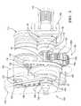
- FIG. 3is a perspective view of an exemplary embodiment of a steer-by-wire handwheel actuator
- FIG. 4is a rear/plan view of a an exemplary embodiment of a steer-by-wire handwheel actuator of FIG. 3;
- FIG. 5is a front/plan view of a an exemplary embodiment of a steer-by-wire handwheel actuator shown in FIG. 4 detailing cross sectional divisions that follow;
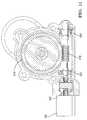
- FIG. 6is a cross section view of an exemplary embodiment of a steer-by-wire handwheel actuator depicted in FIG. 5, Section 6 — 6 ;
- FIG. 7is a cross section view of an exemplary embodiment of a steer-by-wire handwheel actuator depicted in FIG. 5, Section 7 — 7 ;
- FIG. 8is a cross section view of an exemplary embodiment of a steer-by-wire handwheel actuator depicted in FIG. 5, Section 8 — 8 ;
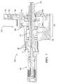
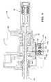
- FIG. 9is a cross section view of a modular unit attached to a steering shaft to provide auxiliary steering resistance
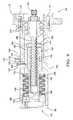
- FIG. 10is a cross section view of an alternative embodiment of the steer-by-wire handwheel actuator of FIG. 3 with a combination worm gear and direct drive power transmission;
- FIG. 11is another cross section view of the alternative embodiment of the steer-by-wire handwheel actuator of FIG. 10 with worm gear power transmission taken perpendicular to the view of FIG. 10 .
- FIG. 1a typical prior art steering system is depicted.
- a steering wheel 10is connected to a steering column 11 which in turn is connected to a steering intermediate shaft 12 via universal joint 14 .
- Another universal joint 16couples intermediate steering shaft 12 to an electric power steering assist assembly (rack assist) 18 . It is evident that mechanical direct connection exists throughout the prior art driving system.
- rack assistelectric power steering assist assembly
- FIG. 2is a schematic representation of a steer-by-wire steering system 600 as it is comprises a controller 400 , a first electro-mechanical actuator 202 and a second electro-mechanical actuator 302 , each actuator 202 , 302 in signal communication 400 a , 400 b with the controller 400 .
- the first and second electro-mechanical actuators 202 , 302comprising a motor, crank arm, steering arm and tie rod, are in turn connected respectively to a first wheel 200 and a second wheel 300 and are operative thereby to steer the wheels 200 , 300 under the command of the controller 400 .
- one actuatoris optionally linked to both road wheels 200 , 300 to operably steer wheels 200 , 300 using one motor to actuate the sole actuator.
- a handwheel actuator 100 of the present disclosureis in signal communication 100 a , 100 b with the controller 400 of the steer-by-wire steering system 600 .
- Handwheel actuator 100is in further communication with an external motive source 500 , such as a driver from whom the handwheel actuator 100 receives steering commands by way of a driver input shaft 102 .
- the controller 400is also operative to receive as input thereto a signal 700 indicative of vehicle velocity, as well as a signal 500 a indicative of the position of the driver input shaft 102 and a signal 500 b indicative of the torque on the driver input shaft 102 .
- Signals 500 a and 500 bare generated from sensors disposed in handwheel actuator 100 proximate shaft 102 .
- the handwheel actuator 100includes a housing 130 , a driver input shaft 102 and a gear train 104 coupled to the driver input shaft 102 .
- the gear train 104comprises a driver feedback pulley 106 , a speed reducer pulley 108 , and a spur gear 110 (See also FIG. 7, as gear train 104 is shaded completely).
- the driver input shaft 102is rotatably positioned between an upper bearing 54 and a lower bearing 56 , and position sensors 20 and torque sensor 22 operably connected to driver input shaft 102 .
- Position sensors 20electronically detect the angular position of the driver input shaft 102
- the torque sensor 22electronically detects and evaluates the torsional force acting on the driver input shaft 102
- the angular displacement of the hand steering wheel 10is detected by sensors 20 , 22 , processed, and applied to a servo motor (not shown) to move steerable wheels (not shown).
- the handwheel actuator 100 of FIGS. 3 and 6includes an electric motor 114 having a motor shaft 116 rotatively driven by the motor 114 . Attached or optionally formed into the motor shaft 116 is a motor pulley 118 . Attached to the motor pulley 118 is a belt 128 positively driving pulley 108 of the gear train 104 . Continuing in FIG.
- the handwheel actuator 100further includes an electro-mechanical brake 120 having an electro-mechanical brake shaft 122 rotatively controlled by the electro-mechanical brake 120 .
- Attached or optionally formed into the electro-mechanical brake shaft 122is a pulley 124 driving a belt 136 operably connected to the gear train 104 . More specifically, the belt 136 is connected to the driver feedback pulley 106 in an exemplary embodiment.
- a preferred embodiment of the handwheel actuatorutilizes an electric sine commutated brushless motor 114 for its primary power transmission because the sine wave commutation provides for a low torque ripple.
- the belt 128 used to transmit the power from the motor 114is a small-cogged belt to provide positive drive, high efficiency, low noise, and nearly zero lash. In using a cogged belt, it has been found to yield approximately 98% efficiency.
- a preferred embodimentuses a magnetic particle brake for the electro-mechanical brake 120 , however alternative embodiments also include electro-rheological fluid devices.
- Magnetorheological fluids suitable for use in the handwheel actuator 100are disclosed in U.S. Pat. Nos. 5,896,965, issued Apr. 27, 1999, to Gopalswamy et al. for a Magnetorheological Fluid Fan Clutch; 5,848,678, issued Dec. 15, 1998, to Johnston et al. for a Passive Magnetorheological Clutch; 5,845,752, issued Dec 8, 1998, to Gopalswamy et al. for a Magnetorheological Fluid Clutch with Minimized Resistance; 5,823,309, issued Oct. 20, 1998, to Gopalswamy et al. for a Magnetorheological Transmission Clutch; and 5,667,715, issued Sep.
- utilizing a magnetic particle brake or a magnetorheological fluid deviceprovides virtually no resistance to a driver input shaft when there is no magnetic force induced by a control module.
- a control moduleenergizes a magnetic field in the magnetic particle brake or the magnetorheological fluid device causing the magnetic particle brake or the magnetorheological fluid device in turn to provide variable passive resistance.
- the variable passive resistancealong with active resistance provided by the electric motor gives the vehicle operator a feel of the road by transferring the resistance upon the steering wheel. Thus, causing the vehicle operator to “feel” or sense the road.
- the handwheel actuator 100illustrates generally a stop mechanism 126 enclosed by housing 130 and comprising the spur gear 110 of the gear train 104 geared to a reducing spur gear 132 .
- Reducing gear 132further comprises interior arcuate stop guides 126 a , 126 b , one on either side of the gear 132 having a first stop pin 126 c disposed within said stop guide 126 a and having a having a second stop pin 126 d disposed within stop guide 126 b , such that as spur gear 110 rotates, reducing gear 132 , and thus spur gear 110 , is mechanically restrained as the first stop pin and second stop pin make simultaneous contact with one pair of two ends 126 e , 126 f of one end of the interior arcuate stop guides 126 a , 126 b (See FIG.
- the other end of the internal arcuate stop guides 126 a , 126 bis not shown.
- the first stop pin and second stop pinare attached to the housing 130 .
- the stop pins 126 c , 126 dare rubber coated and provide over 100 Nm of overload torque capability.
- a modular unit 140is attached to the shaft 102 that acts as a mechanical back-up device to provide auxiliary steering resistance in the steer-by-wire system 600 .
- Modular unit 140allows full lock-to-lock travel of the steering handwheel 10 while providing torsional resistance to handwheel rotation up to a specified saturation torque.
- Modular unit 140provides an adjustable on-center feel and return-to-center mechanism for the steer-by-wire handwheel actuator 100 to provide a passive steering system feel similar to current production hydraulic assisted rack and pinion systems.
- Modular unit 140provides the driver with force feedback throughout the range of travel of the handwheel 10 .
- Modular unit 140comprises a ball screw assembly 142 including a hollow sleeve 144 that slip fits over the ball screw assembly 142 and is rotationally fixed using an anti-rotation pin assembly 148 and a key 149 opposite thereto.
- Rotation pin assembly 148includes a pin 150 slidably engaged against an exterior sleeve 144 .
- Anti-rotation pin assembly 148further includes a pin retainer 152 and screw 154 that is disposed in an aperture 156 of retainer 152 and received in a threaded aperture 158 of housing 162 defining modular unit 140 .
- Pin 150is configured with a slot 163 positioned thereon to allow a portion of retainer 152 to be received therein while maintaining pin 150 slidably disposed in an aperture formed in housing 162 to engage an outside surface of a sleeve 144 when screw 154 is fixed against retainer 152 by tightening screw 154 in threaded aperture 158 .
- Sleeve 144has a channel 164 configured on a periphery thereof to allow axial translation of sleeve 144 while limiting rotation thereof.
- Sleeve 144engages a threaded portion 166 of shaft 102 via a ball nut 168 disposed in sleeve 144 .
- Ball nut 168is retained in sleeve 144 with a ball nut retainer nut 169 .
- Ball nut 168has complementary threads to engage threaded portion 166 .
- Screw shaft 102is supported in a ball bearing assembly 170 that is disposed at one end in housing 162 .
- Bearing assembly 170is retained in housing 162 with a bearing cap 172 that is mechanically fastened to housing 162 with mechanical fasteners 174 .
- a bearing nut 176is engageable with another threaded portion of shaft 102 to fix shaft 102 relative to bearing assembly 170 which is fixed relative to housing 162 .
- an end cap 180encloses a cavity formed in housing 162 .
- a retaining nut 182is threaded onto the end of sleeve 144 and an external spring return nut 196 is threaded into housing 162 .
- a first spring retaining washer 188Disposed against retaining nut 196 and retaining nut 182 is a first spring retaining washer 188 having an aperture allowing ball screw 144 to slide therethrough.
- a second spring retaining washer 190is disposed against a shoulder 192 of sleeve 144 and shoulder 198 of housing 162 . Like washer 188 , washer 190 includes an aperture that allows sleeve 144 to slide therethrough.
- a plurality of biasing members 194is disposed intermediate washers 188 , 190 . Each biasing member is preferably a disc spring or Belleville washer.
- the plurality of biasing members 194is more preferably a stack of disc springs circumferentially disposed about sleeve 144 while allowing translation of sleeve 144 therethrough.
- the stack of disc springsare preferably formed by alternating the orientation of contiguous disc springs to provide a compression type biasing member 194 .
- the spring pack or plurality of biasing members 194is stacked in series to provide desired spring load and maximum travel. The springs are designed and preferably preloaded to a stack height that gives a nonlinear spring rate with a very gradual slope.
- Spring retaining nut 182is preferably configured as an adjustment preload nut that is threaded onto the sleeve 144 and tightened to a specified position to set the appropriate spring preload on the biasing members 194 .
- An external spring return nut 196has exterior threads threadably engaged with complementary threads in housing 162 at end 178 for engaging washer 188 when sleeve 144 translates toward end 178 pushing washer 192 to compress biasing members 194 which push against washer 188 which is prevented from translating toward end 178 by fixed nut 196 .
- biasing members 194When sleeve 144 translates away from end 178 , nut 182 pushes against washer 188 to compress biasing members 194 against washer 192 that is prevented from translating away from end 178 by a shoulder 198 formed in housing 162 .
- the preload on the biasing members 194is configured to provide an identical bias when shaft 102 is rotated in either direction since the spring pack or plurality of biasing members 194 is configured in a parallel arrangement to bias the shaft indicative of a return-to-center position. It will be recognized that although the plurality of biasing members has been described as a single series stack of disc washers, multiple stacks are also contemplated.
- a first stackmay be disposed on one side of ball nut 168 while a second stack is disposed on the other side of ball nut 168 .
- first stackwhen shaft is rotated in one direction, the first stack is compressed and when shaft 102 is rotated in an opposite direction, the second stack is compressed.
- the steering shaft 102rotates at the same speed.
- the ball nut 168 and hence sleeve 144translates left or right in an axial direction relative to shaft 102 shown in FIG. 9 depending on direction of rotation.
- the axial load increasereflects through the ball nut 168 giving an increasing torque feed back to the driver as the hand wheel 10 is turned further from center.
- the mechanismwill not run out of travel since the hand wheel actuator will reach its end of travel stop before maximum travel of the ball nut 168 is reached.
- the ball nut 168will backdrive on the screw due to the axial load imbalance until it reaches the equilibrium load at the center position.
- FIG. 4a preferred embodiment depicted in FIG. 3 is shown from the rear, and FIG. 5 illustrates the front/plan view of FIG. 4 .
- FIG. 5also illustrates three cross sections taken for the Figures referenced above that follow.
- FIGS. 4 and 5illustrate the housing 130 coupled to a bracket 160 for attaching a handwheel actuator to a vehicle mounting interface.
- the handwheel actuator 100is operative to accept as input thereto, firstly, steering commands by way of the driver input shaft 102 from an outside motive source such as a driver 500 , secondly, the first control signal 100 a from the controller 400 to the motor 114 and thirdly, a second control signal 100 b from the controller 400 to the electro-mechanical brake 120 .
- the steering commandsare typically the clockwise or counterclockwise rotation of the driver input shaft 102 .
- the first control signal 100 a originating from the controller 400controls the input to the speed reducer pulley 124 by the motor 114 .
- the second control signal 100 bcontrols a feedback torque directed to the driver input shaft 102 by the electro-mechanical brake 120 .
- the first control signal 100 abased upon the changing operating conditions, activates the motor 114 so as to control speed reducer pulley 124 , namely resisting or assisting to the motion of reducing pulley 108 and allowing controlled rotation thereof.
- the second control signal 100 b from the controller 400activates the electro-mechanical brake 120 so as to provide a resistive torque to the speed reducer 104 by way of the engagement of the electro-mechanical brake 120 to the driver input shaft 102 through the electro-mechanical brake shaft 122 , the pulley 124 , belt 136 , and the driver feedback pulley 106 .
- the resistive torqueresults in a feedback torque that provides the driver 500 with additional tactile response to steering commands.
- Motor 114is in direct drive relationship with motor shaft 116 operably connected to shaft 102 absent a connection via a speed reducer.
- Motor 114includes a motor stator 206 surrounding a motor rotor 208 operably connected to shaft 116 for rotation thereof when rotor 206 is energized.
- Motor shaft 116is connected to driver input shaft 102 via a sleeve assembly 212 having a torsion bar 214 disposed therein for torque sensing by torque sensor 22 .
- Sleeve assembly 212is connected to a worm gear 216 that is engaged to a worm 218 .
- Worm 218is rotatably supported between two bearings 222 and is operably connected to brake 120 via shaft 122 at one end thereof.
- brake 120provides up to about 6 Nm of torque feedback by braking that is transmitted to worm 218 , worm gear 216 , to sleeve assembly 212 , and then to driver input shaft 102
- motor 114provides up to about 4 Nm of torque feedback in conjunction with the 6 Nm from brake 120 to driver input shaft for a total of up to about 10 Nm.
- Motor 114generates the torque through shaft 116 , to sleeve assembly 212 , and then to the driver input shaft 102 .
- worm and worm gear drivewith the direct drive motor connection, zero lash and comparable noise are experienced compared with the belt drive previously described above.
Landscapes
- Engineering & Computer Science (AREA)
- Chemical & Material Sciences (AREA)
- Combustion & Propulsion (AREA)
- Transportation (AREA)
- Mechanical Engineering (AREA)
- Steering Control In Accordance With Driving Conditions (AREA)
- Power Steering Mechanism (AREA)
- Regulating Braking Force (AREA)
- Transmission Of Braking Force In Braking Systems (AREA)
Abstract
Description
Claims (40)
Priority Applications (2)
| Application Number | Priority Date | Filing Date | Title |
|---|---|---|---|
| US10/163,927US6817437B2 (en) | 2001-06-19 | 2002-06-06 | Steer-by wire handwheel actuator |
| US10/988,472US20050087384A1 (en) | 2001-06-19 | 2004-11-12 | Steer-by-wire handwheel actuator |
Applications Claiming Priority (2)
| Application Number | Priority Date | Filing Date | Title |
|---|---|---|---|
| US29934201P | 2001-06-19 | 2001-06-19 | |
| US10/163,927US6817437B2 (en) | 2001-06-19 | 2002-06-06 | Steer-by wire handwheel actuator |
Related Child Applications (1)
| Application Number | Title | Priority Date | Filing Date |
|---|---|---|---|
| US10/988,472ContinuationUS20050087384A1 (en) | 2001-06-19 | 2004-11-12 | Steer-by-wire handwheel actuator |
Publications (2)
| Publication Number | Publication Date |
|---|---|
| US20020189888A1 US20020189888A1 (en) | 2002-12-19 |
| US6817437B2true US6817437B2 (en) | 2004-11-16 |
Family
ID=23154371
Family Applications (2)
| Application Number | Title | Priority Date | Filing Date |
|---|---|---|---|
| US10/163,927Expired - Fee RelatedUS6817437B2 (en) | 2001-06-19 | 2002-06-06 | Steer-by wire handwheel actuator |
| US10/988,472AbandonedUS20050087384A1 (en) | 2001-06-19 | 2004-11-12 | Steer-by-wire handwheel actuator |
Family Applications After (1)
| Application Number | Title | Priority Date | Filing Date |
|---|---|---|---|
| US10/988,472AbandonedUS20050087384A1 (en) | 2001-06-19 | 2004-11-12 | Steer-by-wire handwheel actuator |
Country Status (2)
| Country | Link |
|---|---|
| US (2) | US6817437B2 (en) |
| WO (1) | WO2002102640A2 (en) |
Cited By (37)
| Publication number | Priority date | Publication date | Assignee | Title |
|---|---|---|---|---|
| US20040104067A1 (en)* | 2001-03-28 | 2004-06-03 | Burkhard Fishbach | Drive device of a motor vehicle axle steering module and an electromechanical motor vehicle steering system |
| US20040238300A1 (en)* | 2003-05-30 | 2004-12-02 | Deere & Company, A Delaware Corporation | Magnetorheological fluid brake and force-feedback system for a steering mechanism |
| US20050087384A1 (en)* | 2001-06-19 | 2005-04-28 | Delphi Technologies, Inc. | Steer-by-wire handwheel actuator |
| US20050274565A1 (en)* | 2004-06-09 | 2005-12-15 | Greenwell Randall G | Steer by wire motor control algorithm |
| US6978858B1 (en)* | 2004-06-14 | 2005-12-27 | Bischoff David R | Visual reference control apparatus for hydraulic actuator systems |
| US20060065469A1 (en)* | 2002-10-09 | 2006-03-30 | Aktiebolaget Skf | Feedback assembly for an electronically controlled electro-mechanical actuating unit for a motor vehicle |
| US20060201733A1 (en)* | 2000-11-18 | 2006-09-14 | Peter Dominke | Clutch for steer-by-wire steering system |
| US20070096449A1 (en)* | 2005-10-31 | 2007-05-03 | Honda Motor Co., Ltd. | Steering shaft support structure and vehicle |
| US20070257461A1 (en)* | 2006-05-08 | 2007-11-08 | Lutz David G | Rotary damper resistance for steering system |
| US20090194357A1 (en)* | 2008-02-05 | 2009-08-06 | Crown Equipment Corporation | Materials handling vehicle having a steer system including a tactile feedback device |
| US8011678B1 (en) | 2007-09-20 | 2011-09-06 | Hydro-Gear Limited Partnership | Steering system for a zero-turn radius vehicle |
| US20130306396A1 (en)* | 2012-05-16 | 2013-11-21 | Jtekt Corporation | Steering system |
| US8844658B2 (en) | 2006-07-07 | 2014-09-30 | Hydro-Gear Limited Partnership | Electronic steering apparatus |
| US8950520B2 (en) | 2006-07-07 | 2015-02-10 | Hydro-Gear Limited Partnership | Front steering module for a zero turn radius vehicle |
| US9227656B2 (en) | 2013-03-26 | 2016-01-05 | Jtekt Corporation | Electric power steering system |
| US9499202B2 (en)* | 2015-04-15 | 2016-11-22 | Delphi Technologies, Inc. | Steering system and method for autonomous vehicles |
| US20180029632A1 (en)* | 2016-08-01 | 2018-02-01 | Steering Solutions Ip Holding Corporation | Electric power steering column assembly |
| CN108202727A (en)* | 2016-12-16 | 2018-06-26 | 通用汽车环球科技运作有限责任公司 | Device for force feedback based on spring |
| US10029676B2 (en) | 2014-01-29 | 2018-07-24 | Steering Solutions Ip Holding Corporation | Hands on steering wheel detect |
| US10029725B2 (en) | 2015-12-03 | 2018-07-24 | Steering Solutions Ip Holding Corporation | Torque feedback system for a steer-by-wire vehicle, vehicle having steering column, and method of providing feedback in vehicle |
| US10112639B2 (en) | 2015-06-26 | 2018-10-30 | Steering Solutions Ip Holding Corporation | Vehicle steering arrangement and method of making same |
| US10239552B2 (en) | 2016-10-14 | 2019-03-26 | Steering Solutions Ip Holding Corporation | Rotation control assembly for a steering column |
| US10310605B2 (en) | 2016-11-15 | 2019-06-04 | Steering Solutions Ip Holding Corporation | Haptic feedback for steering system controls |
| US10384708B2 (en) | 2016-09-12 | 2019-08-20 | Steering Solutions Ip Holding Corporation | Intermediate shaft assembly for steer-by-wire steering system |
| US10399591B2 (en) | 2016-10-03 | 2019-09-03 | Steering Solutions Ip Holding Corporation | Steering compensation with grip sensing |
| US10421485B2 (en)* | 2016-02-24 | 2019-09-24 | Steering Solutions Ip Holding Corporation | Steering system having a pressure sensor |
| US10442441B2 (en) | 2015-06-15 | 2019-10-15 | Steering Solutions Ip Holding Corporation | Retractable handwheel gesture control |
| US10449927B2 (en) | 2017-04-13 | 2019-10-22 | Steering Solutions Ip Holding Corporation | Steering system having anti-theft capabilities |
| US10481602B2 (en) | 2016-10-17 | 2019-11-19 | Steering Solutions Ip Holding Corporation | Sensor fusion for autonomous driving transition control |
| US10496102B2 (en) | 2016-04-11 | 2019-12-03 | Steering Solutions Ip Holding Corporation | Steering system for autonomous vehicle |
| US10562561B2 (en) | 2016-04-25 | 2020-02-18 | Steering Solutions Ip Holding Corporation | Electrical power steering control using system state predictions |
| US10780915B2 (en) | 2016-12-07 | 2020-09-22 | Steering Solutions Ip Holding Corporation | Vehicle steering system having a user experience based automated driving to manual driving transition system and method |
| US11181172B2 (en)* | 2018-06-14 | 2021-11-23 | Mando Corporation | Belt drive mechanism with gear back-up |
| US11334074B2 (en) | 2018-11-12 | 2022-05-17 | Infosys Limited | System and method for integrated auto-steering and auto-braking mechanism in autonomous vehicles as a retro fit |
| US20220243791A1 (en)* | 2021-01-29 | 2022-08-04 | ZF Automotive UK Limited | Travel limiter for a vehicle steering column |
| US20240034392A1 (en)* | 2019-05-14 | 2024-02-01 | Hl Mando Corporation | Vehicle steering apparatus |
| US12139215B1 (en)* | 2022-01-11 | 2024-11-12 | Waymo Llc | Method for detection and mitigation of blocked steering actuator |
Families Citing this family (49)
| Publication number | Priority date | Publication date | Assignee | Title |
|---|---|---|---|---|
| US6761243B2 (en)* | 2001-12-31 | 2004-07-13 | Visteon Global Technologies, Inc. | Steering control with variable damper assistance and method implementing the same |
| US6666294B2 (en)* | 2002-01-10 | 2003-12-23 | Dayco Products, Llc | Belt driven mechanical boost power steering |
| US6598695B1 (en)* | 2002-01-30 | 2003-07-29 | Delphi Technologies, Inc. | Drive-by wire steering systems having a stop mechanism |
| US6708794B2 (en)* | 2002-01-30 | 2004-03-23 | Delphi Technologies, Inc. | Drive-by-wire steering systems having steering wheel return mechanism |
| US6892605B2 (en)* | 2002-03-04 | 2005-05-17 | Delphi Technologies, Inc. | Hand wheel actuator having stationary hub |
| WO2004069628A2 (en)* | 2003-02-04 | 2004-08-19 | Douglas Autotech Corporation | Steering assembly with tactile feedback |
| EP1628869B1 (en)* | 2003-05-23 | 2008-10-01 | Continental Teves AG & Co. oHG | Superimposed steering system |
| JP3817677B2 (en)* | 2003-05-30 | 2006-09-06 | 現代自動車株式会社 | Independent steer-by-wire system steering actuator |
| CA2438981C (en) | 2003-08-29 | 2010-01-12 | Teleflex Canada Incorporated | Steer by wire helm |
| US6926112B2 (en)* | 2003-10-16 | 2005-08-09 | Visteon Global Technologies, Inc. | End of travel system and method for steer by wire systems |
| US7174987B2 (en)* | 2003-10-16 | 2007-02-13 | Visteon Global Technologies, Inc. | End of travel feature for steer by wire vehicle |
| US6899196B2 (en)* | 2003-10-16 | 2005-05-31 | Visteon Global Technologies, Inc. | Driver interface system for steer-by-wire system |
| DE102004009906B3 (en)* | 2004-02-26 | 2005-07-28 | Nacam Deutschland Gmbh | Rolling bearing for steering column has rheologically active substance in intermediate cavity of bearing |
| US7258072B2 (en) | 2004-08-26 | 2007-08-21 | Teleflex Canada Incorporated | Multiple steer by wire helm system |
| EP1954547B1 (en)* | 2005-11-30 | 2009-09-02 | Svend Egenfeldt | A remote control system |
| EP2060800B1 (en)* | 2007-11-14 | 2011-01-12 | Magneti Marelli S.p.A. | Combined actuator with rheological control brake |
| WO2022170050A1 (en)* | 2021-02-05 | 2022-08-11 | Lord Corporation | Active/semi-active steer-by-wire system and method |
| CN103171613A (en)* | 2013-03-07 | 2013-06-26 | 青岛科技大学 | Vehicle steer-by-wire mode switching limit device |
| US9199667B2 (en) | 2014-03-14 | 2015-12-01 | Mitsubishi Electric Research Laboratories, Inc. | System and method for semi-autonomous driving of vehicles |
| US10589774B2 (en) | 2015-05-01 | 2020-03-17 | Steering Solutions Ip Holding Corporation | Counter rotation steering wheel |
| US20160375931A1 (en) | 2015-06-25 | 2016-12-29 | Steering Solutions Ip Holding Corporation | Rotation control system for a steering wheel and method |
| DE102016113802A1 (en)* | 2015-07-28 | 2017-02-02 | Steering Solutions Ip Holding Corporation | Power assist system with spindle nut, brake booster actuator and method |
| DE102016113803A1 (en) | 2015-07-28 | 2017-02-02 | Steering Solutions Ip Holding Corporation | PULLEY ASSEMBLY WITH IDLE ROLL, POWER SUPPORT SYSTEM WITH PULLEY ASSEMBLY AND METHOD |
| US10160472B2 (en) | 2015-10-20 | 2018-12-25 | Steering Solutions Ip Holding Corporation | Steering column with stationary hub |
| US10160473B2 (en) | 2016-09-13 | 2018-12-25 | Steering Solutions Ip Holding Corporation | Steering column decoupling system |
| JP6558393B2 (en) | 2017-04-06 | 2019-08-14 | トヨタ自動車株式会社 | Course setting device and course setting method |
| US10683030B2 (en)* | 2017-09-22 | 2020-06-16 | GM Global Technology Operations LLC | Fluid flow control mechanism for a steering wheel emulator |
| US10870447B2 (en)* | 2017-12-07 | 2020-12-22 | Deere & Company | Brake system for steering feedback |
| US10676129B2 (en)* | 2018-06-25 | 2020-06-09 | Steering Solutions Ip Holding Corporation | Driver notification using handwheel actuators in steer-by-wire systems |
| DE102018115650A1 (en) | 2018-06-28 | 2020-01-02 | Schaeffler Technologies AG & Co. KG | Steering wheel unit for detecting a steering movement of a steering wheel for an electromechanical steering system |
| DE102018115565A1 (en) | 2018-06-28 | 2020-01-02 | Schaeffler Technologies AG & Co. KG | Steering wheel unit for generating a feedback force on a steering wheel for an electromechanical steering system |
| DE102018115908A1 (en) | 2018-07-02 | 2020-01-02 | Schaeffler Technologies AG & Co. KG | Steering wheel unit for detecting a steering movement of a steering wheel for an electromechanical steering system |
| DE102018115937B4 (en) | 2018-07-02 | 2025-07-03 | Schaeffler Technologies AG & Co. KG | Steering wheel unit for detecting a steering movement of a steering wheel for an electromechanical steering system |
| DE102018116732A1 (en) | 2018-07-11 | 2020-01-16 | Schaeffler Technologies AG & Co. KG | Steering wheel unit for generating a feedback force on a steering wheel for an electromechanical steering system |
| DE102018116733A1 (en) | 2018-07-11 | 2020-01-16 | Schaeffler Technologies AG & Co. KG | Steering wheel unit for detecting a steering movement of a steering wheel for an electromechanical steering system |
| DE102018120197A1 (en) | 2018-08-20 | 2020-02-20 | Schaeffler Technologies AG & Co. KG | Steering unit for steer-by-wire steering of a motor vehicle |
| GB2582976B (en)* | 2019-04-12 | 2023-12-06 | Zf Automotive Uk Ltd | A steering column assembly for a vehicle |
| US11584426B2 (en)* | 2019-04-24 | 2023-02-21 | Steering Solutions Ip Holding Corporation | Rotational centering device for steering column |
| CN112537365B (en)* | 2019-09-20 | 2024-10-18 | 舍弗勒技术股份两合公司 | Steering wheel unit for detecting steering movement of steering wheel of electromechanical steering system |
| CN112550429A (en)* | 2019-09-25 | 2021-03-26 | 舍弗勒技术股份两合公司 | Steering wheel unit for an electromechanical steering system for sensing steering movements of a steering wheel |
| KR20210051818A (en)* | 2019-10-31 | 2021-05-10 | 주식회사 만도 | Steer-by-wire type steering apparatus |
| CN110979450B (en)* | 2019-12-23 | 2024-07-05 | 广东工业大学 | Steering mechanism of formula car capable of being freely switched |
| CN111060333B (en)* | 2020-01-02 | 2024-06-07 | 浙江工业大学 | Electric power steering system performance test equipment based on industrial handling vehicles |
| US11204082B2 (en)* | 2020-01-17 | 2021-12-21 | Steering Solutions Ip Holding Corporation | Steer by wire rotational travel stop |
| US11370483B2 (en)* | 2020-01-27 | 2022-06-28 | Sensata Technologies, Inc. | Steer by wire system with dynamic braking and endstop cushioning for haptic feel |
| US11661099B2 (en) | 2021-02-11 | 2023-05-30 | Ford Global Technologies, Llc | Handwheel actuator modular interface |
| JP7361209B2 (en)* | 2021-03-02 | 2023-10-13 | 本田技研工業株式会社 | vehicle steering system |
| CN113415338B (en)* | 2021-07-12 | 2022-11-04 | 上海汽车工业(集团)总公司 | Steering-by-wire road sensing feedback device |
| US20250010906A1 (en)* | 2023-07-05 | 2025-01-09 | Steering Solutions Ip Holding Corporation | Steer-by-wire steering column |
Citations (49)
| Publication number | Priority date | Publication date | Assignee | Title |
|---|---|---|---|---|
| JPS60259570A (en) | 1984-06-04 | 1985-12-21 | Kayaba Ind Co Ltd | Power steering apparatus operated by electric motor |
| US4771846A (en)* | 1986-09-22 | 1988-09-20 | Trw Inc. | Apparatus for establishing steering feel |
| JPH01115778A (en) | 1987-10-30 | 1989-05-09 | Jidosha Kiki Co Ltd | Rear wheel steering device for four-wheel steering car |
| US4860844A (en) | 1988-04-29 | 1989-08-29 | Eaton Corporation | Power steering system |
| EP0278366B1 (en) | 1987-02-03 | 1991-03-06 | Kabushiki Kaisha Toyota Chuo Kenkyusho | Apparatus for controlling steering of wheels of a vehicle |
| US5097917A (en)* | 1987-12-26 | 1992-03-24 | Honda Giken Kogyo Kabushiki Kaisha | Steering system of vehicle |
| US5228757A (en) | 1990-07-02 | 1993-07-20 | Nissan Motor Co., Ltd. | System for controlling behavior of vehicle during braking and during a steering maneuver |
| US5251135A (en) | 1990-09-25 | 1993-10-05 | Honda Giken Kogyo Kabushiki Kaisha | Vehicle steering control system |
| US5347458A (en) | 1990-09-25 | 1994-09-13 | Honda Giken Kogyo Kabushiki Kaisha | Vehicle steering control system |
| US5374877A (en) | 1992-08-05 | 1994-12-20 | Nissan Motor Co., Ltd. | Apparatus and method of controlling power of electric motor car |
| US5473225A (en) | 1992-04-21 | 1995-12-05 | Kabushiki Kaisha Toshiba | Electric motor vehicle control apparatus and method for reducing the occurrence of wheel slip |
| JPH0834353A (en) | 1994-05-18 | 1996-02-06 | Toyota Motor Corp | Vehicle steering system |
| US5576957A (en) | 1994-03-02 | 1996-11-19 | Honda Giken Kogyo Kabushiki Kaisha | Control system for a front and rear wheel steering vehicle |
| US5653304A (en) | 1994-04-20 | 1997-08-05 | University Of Arkansas, N.A. | Lever steering system |
| US5667715A (en) | 1996-04-08 | 1997-09-16 | General Motors Corporation | Magnetorheological fluids |
| US5668722A (en) | 1995-10-02 | 1997-09-16 | General Motors Corporation | Electric power steering control |
| US5740040A (en) | 1994-12-21 | 1998-04-14 | Mitsubishi Denki Kabushiki Kaisha | Electric power steering apparatus with enhanced road feel |
| US5803202A (en)* | 1995-10-20 | 1998-09-08 | Mercedes-Benz Ag | Reaction simulator especially for a vehicle steering system |
| US5823309A (en) | 1997-05-23 | 1998-10-20 | General Motors Corporation | Magnetorheological transmission clutch |
| US5828972A (en) | 1991-09-27 | 1998-10-27 | Honda Giken Kogyo Kabushiki Kaisha | Motor vehicle steering system with automatic disturbance suppression |
| US5829547A (en) | 1995-07-06 | 1998-11-03 | Jidosha Kiki Co., Ltd. | Power steering apparatus with pump driven by pulse width modulated controlled, brushless d.c. electric motor |
| US5845752A (en) | 1997-06-02 | 1998-12-08 | General Motors Corporation | Magnetorheological fluid clutch with minimized reluctance |
| US5848678A (en) | 1997-06-04 | 1998-12-15 | General Motors Corporation | Passive magnetorheological clutch |
| US5896965A (en) | 1997-06-02 | 1999-04-27 | General Motors Corporation | Magnetorheological fluid fan clutch |
| US5896942A (en)* | 1996-06-26 | 1999-04-27 | Mercedes-Benz Ag | Steering apparatus for a motor vehicle |
| US5925083A (en) | 1996-12-07 | 1999-07-20 | Deutsche Forchungsanstalt Fur Luft Und Raumfahrt E.V. | Method of correcting steering of a road driven vehicle |
| US6018691A (en) | 1993-06-29 | 2000-01-25 | Honda Giken Kogyo Kabushiki Kaisha | Vehicle steering system |
| EP0858408B1 (en) | 1995-11-03 | 2000-02-23 | DaimlerChrysler AG | Servo steering for motor vehicles |
| EP0985591A2 (en) | 1998-09-09 | 2000-03-15 | DaimlerChrysler AG | Steering system for non track-bound motor vehicles |
| GB2341588A (en) | 1998-09-17 | 2000-03-22 | Daimler Chrysler Ag | A vehicle 'steer-by-wire' system using redundant control systems |
| WO2000034106A1 (en) | 1998-12-09 | 2000-06-15 | Delphi Technologies, Inc. | A vehicle steering command module with an adjustable steering rim diameter |
| US6097286A (en) | 1997-09-30 | 2000-08-01 | Reliance Electric Technologies, Llc | Steer by wire system with feedback |
| US6098296A (en) | 1998-12-03 | 2000-08-08 | Delco Electronics Corp. | Wheel alignment system and method for vehicles having steer-by-wire steering system |
| US6102151A (en) | 1997-07-24 | 2000-08-15 | Honda Giken Kogyo Kabushiki Kaisha | Electric power steering apparatus |
| US6152254A (en) | 1998-06-23 | 2000-11-28 | Techco Corporation | Feedback and servo control for electric power steering system with hydraulic transmission |
| US6176341B1 (en) | 1999-02-01 | 2001-01-23 | Delphi Technologies, Inc. | Vehicle steering system having master/slave configuration and method therefor |
| US6179394B1 (en) | 1998-11-09 | 2001-01-30 | General Motors Corporation | Active brake balance control method |
| US6208923B1 (en) | 1998-08-01 | 2001-03-27 | Robert Bosch Gmbh | Fault-tolerant electromechanical steer-by-wire steering actuator |
| US6279674B1 (en) | 1996-08-09 | 2001-08-28 | Volkswagen Ag | Arrangement and method for steering a motor vehicle |
| US6279675B1 (en) | 1998-09-02 | 2001-08-28 | Daimlerchrysler Ag | Steering system for non-tracked motor vehicles |
| US6283859B1 (en)* | 1998-11-10 | 2001-09-04 | Lord Corporation | Magnetically-controllable, active haptic interface system and apparatus |
| US6285963B1 (en) | 1997-10-14 | 2001-09-04 | Schlumberger Technologies, Inc. | Measuring signals in a tester system |
| US6283243B1 (en) | 1998-09-17 | 2001-09-04 | Daimchrysler Ag | Method for operating a vehicle steering system |
| US6298940B1 (en) | 1998-06-27 | 2001-10-09 | Daimlerchrysler Ag | Power steering system for motor vehicles |
| US6339419B1 (en)* | 1998-11-10 | 2002-01-15 | Lord Corporation | Magnetically-controllable, semi-active haptic interface system and apparatus |
| US20020005315A1 (en)* | 2000-05-04 | 2002-01-17 | Thomas Kind | Steering system for a motor vehicle |
| US6389343B1 (en)* | 2000-09-29 | 2002-05-14 | Caterpillar Inc. | Steering resistance device |
| US6547031B1 (en)* | 2001-10-16 | 2003-04-15 | Delphi Technologies, Inc. | Front wheel steering variable control actuator |
| US6585540B2 (en)* | 2000-12-06 | 2003-07-01 | Pulse Engineering | Shielded microelectronic connector assembly and method of manufacturing |
Family Cites Families (4)
| Publication number | Priority date | Publication date | Assignee | Title |
|---|---|---|---|---|
| FR2778853B1 (en)* | 1998-05-19 | 2000-12-22 | Sedat | INJECTION SYRINGE WITH SPRING LOADED NEEDLE PROTECTOR |
| US6481526B1 (en)* | 2000-11-13 | 2002-11-19 | Delphi Technologies, Inc. | Steer-by-wire handwheel actuator incorporating mechanism for variable end-of-travel |
| US6557662B1 (en)* | 2000-11-22 | 2003-05-06 | Visteon Global Technologies, Inc. | Magneto-rheological simulated steering feel system |
| WO2002102640A2 (en)* | 2001-06-19 | 2002-12-27 | Delphi Technologies, Inc. | Steer-by-wire-handwheel actuator |
- 2002
- 2002-06-06WOPCT/US2002/018041patent/WO2002102640A2/enactiveApplication Filing
- 2002-06-06USUS10/163,927patent/US6817437B2/ennot_activeExpired - Fee Related
- 2004
- 2004-11-12USUS10/988,472patent/US20050087384A1/ennot_activeAbandoned
Patent Citations (49)
| Publication number | Priority date | Publication date | Assignee | Title |
|---|---|---|---|---|
| JPS60259570A (en) | 1984-06-04 | 1985-12-21 | Kayaba Ind Co Ltd | Power steering apparatus operated by electric motor |
| US4771846A (en)* | 1986-09-22 | 1988-09-20 | Trw Inc. | Apparatus for establishing steering feel |
| EP0278366B1 (en) | 1987-02-03 | 1991-03-06 | Kabushiki Kaisha Toyota Chuo Kenkyusho | Apparatus for controlling steering of wheels of a vehicle |
| JPH01115778A (en) | 1987-10-30 | 1989-05-09 | Jidosha Kiki Co Ltd | Rear wheel steering device for four-wheel steering car |
| US5097917A (en)* | 1987-12-26 | 1992-03-24 | Honda Giken Kogyo Kabushiki Kaisha | Steering system of vehicle |
| US4860844A (en) | 1988-04-29 | 1989-08-29 | Eaton Corporation | Power steering system |
| US5228757A (en) | 1990-07-02 | 1993-07-20 | Nissan Motor Co., Ltd. | System for controlling behavior of vehicle during braking and during a steering maneuver |
| US5251135A (en) | 1990-09-25 | 1993-10-05 | Honda Giken Kogyo Kabushiki Kaisha | Vehicle steering control system |
| US5347458A (en) | 1990-09-25 | 1994-09-13 | Honda Giken Kogyo Kabushiki Kaisha | Vehicle steering control system |
| US5828972A (en) | 1991-09-27 | 1998-10-27 | Honda Giken Kogyo Kabushiki Kaisha | Motor vehicle steering system with automatic disturbance suppression |
| US5473225A (en) | 1992-04-21 | 1995-12-05 | Kabushiki Kaisha Toshiba | Electric motor vehicle control apparatus and method for reducing the occurrence of wheel slip |
| US5374877A (en) | 1992-08-05 | 1994-12-20 | Nissan Motor Co., Ltd. | Apparatus and method of controlling power of electric motor car |
| US6018691A (en) | 1993-06-29 | 2000-01-25 | Honda Giken Kogyo Kabushiki Kaisha | Vehicle steering system |
| US5576957A (en) | 1994-03-02 | 1996-11-19 | Honda Giken Kogyo Kabushiki Kaisha | Control system for a front and rear wheel steering vehicle |
| US5653304A (en) | 1994-04-20 | 1997-08-05 | University Of Arkansas, N.A. | Lever steering system |
| JPH0834353A (en) | 1994-05-18 | 1996-02-06 | Toyota Motor Corp | Vehicle steering system |
| US5740040A (en) | 1994-12-21 | 1998-04-14 | Mitsubishi Denki Kabushiki Kaisha | Electric power steering apparatus with enhanced road feel |
| US5829547A (en) | 1995-07-06 | 1998-11-03 | Jidosha Kiki Co., Ltd. | Power steering apparatus with pump driven by pulse width modulated controlled, brushless d.c. electric motor |
| US5668722A (en) | 1995-10-02 | 1997-09-16 | General Motors Corporation | Electric power steering control |
| US5803202A (en)* | 1995-10-20 | 1998-09-08 | Mercedes-Benz Ag | Reaction simulator especially for a vehicle steering system |
| EP0858408B1 (en) | 1995-11-03 | 2000-02-23 | DaimlerChrysler AG | Servo steering for motor vehicles |
| US5667715A (en) | 1996-04-08 | 1997-09-16 | General Motors Corporation | Magnetorheological fluids |
| US5896942A (en)* | 1996-06-26 | 1999-04-27 | Mercedes-Benz Ag | Steering apparatus for a motor vehicle |
| US6279674B1 (en) | 1996-08-09 | 2001-08-28 | Volkswagen Ag | Arrangement and method for steering a motor vehicle |
| US5925083A (en) | 1996-12-07 | 1999-07-20 | Deutsche Forchungsanstalt Fur Luft Und Raumfahrt E.V. | Method of correcting steering of a road driven vehicle |
| US5823309A (en) | 1997-05-23 | 1998-10-20 | General Motors Corporation | Magnetorheological transmission clutch |
| US5896965A (en) | 1997-06-02 | 1999-04-27 | General Motors Corporation | Magnetorheological fluid fan clutch |
| US5845752A (en) | 1997-06-02 | 1998-12-08 | General Motors Corporation | Magnetorheological fluid clutch with minimized reluctance |
| US5848678A (en) | 1997-06-04 | 1998-12-15 | General Motors Corporation | Passive magnetorheological clutch |
| US6102151A (en) | 1997-07-24 | 2000-08-15 | Honda Giken Kogyo Kabushiki Kaisha | Electric power steering apparatus |
| US6097286A (en) | 1997-09-30 | 2000-08-01 | Reliance Electric Technologies, Llc | Steer by wire system with feedback |
| US6285963B1 (en) | 1997-10-14 | 2001-09-04 | Schlumberger Technologies, Inc. | Measuring signals in a tester system |
| US6152254A (en) | 1998-06-23 | 2000-11-28 | Techco Corporation | Feedback and servo control for electric power steering system with hydraulic transmission |
| US6298940B1 (en) | 1998-06-27 | 2001-10-09 | Daimlerchrysler Ag | Power steering system for motor vehicles |
| US6208923B1 (en) | 1998-08-01 | 2001-03-27 | Robert Bosch Gmbh | Fault-tolerant electromechanical steer-by-wire steering actuator |
| US6279675B1 (en) | 1998-09-02 | 2001-08-28 | Daimlerchrysler Ag | Steering system for non-tracked motor vehicles |
| EP0985591A2 (en) | 1998-09-09 | 2000-03-15 | DaimlerChrysler AG | Steering system for non track-bound motor vehicles |
| GB2341588A (en) | 1998-09-17 | 2000-03-22 | Daimler Chrysler Ag | A vehicle 'steer-by-wire' system using redundant control systems |
| US6283243B1 (en) | 1998-09-17 | 2001-09-04 | Daimchrysler Ag | Method for operating a vehicle steering system |
| US6179394B1 (en) | 1998-11-09 | 2001-01-30 | General Motors Corporation | Active brake balance control method |
| US6283859B1 (en)* | 1998-11-10 | 2001-09-04 | Lord Corporation | Magnetically-controllable, active haptic interface system and apparatus |
| US6339419B1 (en)* | 1998-11-10 | 2002-01-15 | Lord Corporation | Magnetically-controllable, semi-active haptic interface system and apparatus |
| US6098296A (en) | 1998-12-03 | 2000-08-08 | Delco Electronics Corp. | Wheel alignment system and method for vehicles having steer-by-wire steering system |
| WO2000034106A1 (en) | 1998-12-09 | 2000-06-15 | Delphi Technologies, Inc. | A vehicle steering command module with an adjustable steering rim diameter |
| US6176341B1 (en) | 1999-02-01 | 2001-01-23 | Delphi Technologies, Inc. | Vehicle steering system having master/slave configuration and method therefor |
| US20020005315A1 (en)* | 2000-05-04 | 2002-01-17 | Thomas Kind | Steering system for a motor vehicle |
| US6389343B1 (en)* | 2000-09-29 | 2002-05-14 | Caterpillar Inc. | Steering resistance device |
| US6585540B2 (en)* | 2000-12-06 | 2003-07-01 | Pulse Engineering | Shielded microelectronic connector assembly and method of manufacturing |
| US6547031B1 (en)* | 2001-10-16 | 2003-04-15 | Delphi Technologies, Inc. | Front wheel steering variable control actuator |
Non-Patent Citations (1)
| Title |
|---|
| J.Y. Wong, Ph.D., "Chapter Five: Handling Characteristics of Road Vehicles," Theory of Ground Vehicles, 1978, pp. 210-214. |
Cited By (59)
| Publication number | Priority date | Publication date | Assignee | Title |
|---|---|---|---|---|
| US7232006B2 (en)* | 2000-11-18 | 2007-06-19 | Robert Bosch Gmbh | Clutch for steer-by-wire steering system |
| US20060201733A1 (en)* | 2000-11-18 | 2006-09-14 | Peter Dominke | Clutch for steer-by-wire steering system |
| US20040104067A1 (en)* | 2001-03-28 | 2004-06-03 | Burkhard Fishbach | Drive device of a motor vehicle axle steering module and an electromechanical motor vehicle steering system |
| US7044263B2 (en)* | 2001-03-28 | 2006-05-16 | Continental Teves Ag&Co., Ohg | Motorized system for vehicle steering |
| US20050087384A1 (en)* | 2001-06-19 | 2005-04-28 | Delphi Technologies, Inc. | Steer-by-wire handwheel actuator |
| US20060065469A1 (en)* | 2002-10-09 | 2006-03-30 | Aktiebolaget Skf | Feedback assembly for an electronically controlled electro-mechanical actuating unit for a motor vehicle |
| AU2004200947B2 (en)* | 2003-05-30 | 2010-09-23 | Deere & Company | Magnetorheological fluid brake and force-feedback system for a steering mechanism |
| AU2004200947B8 (en)* | 2003-05-30 | 2011-01-20 | Deere & Company | Magnetorheological fluid brake and force-feedback system for a steering mechanism |
| US20040238300A1 (en)* | 2003-05-30 | 2004-12-02 | Deere & Company, A Delaware Corporation | Magnetorheological fluid brake and force-feedback system for a steering mechanism |
| US6910699B2 (en)* | 2003-05-30 | 2005-06-28 | Deere & Company | Magnetorheological fluid brake and force-feedback system for a steering mechanism |
| US20050274565A1 (en)* | 2004-06-09 | 2005-12-15 | Greenwell Randall G | Steer by wire motor control algorithm |
| US6978858B1 (en)* | 2004-06-14 | 2005-12-27 | Bischoff David R | Visual reference control apparatus for hydraulic actuator systems |
| US20070096449A1 (en)* | 2005-10-31 | 2007-05-03 | Honda Motor Co., Ltd. | Steering shaft support structure and vehicle |
| US7967102B2 (en)* | 2005-10-31 | 2011-06-28 | Honda Motor Co., Ltd | Steering shaft support structure and vehicle |
| US20070257461A1 (en)* | 2006-05-08 | 2007-11-08 | Lutz David G | Rotary damper resistance for steering system |
| US7594563B2 (en)* | 2006-05-08 | 2009-09-29 | Cnh America Llc | Rotary damper resistance for steering system |
| US9854736B2 (en) | 2006-07-07 | 2018-01-02 | Hydro-Gear Limited Partnership | Electronic steering apparatus |
| US8950520B2 (en) | 2006-07-07 | 2015-02-10 | Hydro-Gear Limited Partnership | Front steering module for a zero turn radius vehicle |
| US8844658B2 (en) | 2006-07-07 | 2014-09-30 | Hydro-Gear Limited Partnership | Electronic steering apparatus |
| US10035537B2 (en) | 2006-07-07 | 2018-07-31 | Hydro-Gear Limited Partnership | Front steering module for a zero turn radius vehicle |
| US8262109B1 (en) | 2007-09-20 | 2012-09-11 | Hydro-Gear Limited Partnership | Steering system for a zero-turn radius vehicle |
| US8152183B1 (en) | 2007-09-20 | 2012-04-10 | Hydro-Gear Limited Partnership | Steering system for a zero-turn radius vehicle |
| US8011678B1 (en) | 2007-09-20 | 2011-09-06 | Hydro-Gear Limited Partnership | Steering system for a zero-turn radius vehicle |
| US8172033B2 (en) | 2008-02-05 | 2012-05-08 | Crown Equipment Corporation | Materials handling vehicle with a module capable of changing a steerable wheel to control handle position ratio |
| US8412431B2 (en) | 2008-02-05 | 2013-04-02 | Crown Equipment Corporation | Materials handling vehicle having a control apparatus for determining an acceleration value |
| US8718890B2 (en) | 2008-02-05 | 2014-05-06 | Crown Equipment Corporation | Materials handling vehicle having a control apparatus for determining an acceleration value |
| US7980352B2 (en) | 2008-02-05 | 2011-07-19 | Crown Equipment Corporation | Materials handling vehicle having a steer system including a tactile feedback device |
| US7849955B2 (en) | 2008-02-05 | 2010-12-14 | Crown Equipment Corporation | Materials handling vehicle having a steer system including a tactile feedback device |
| US9421963B2 (en) | 2008-02-05 | 2016-08-23 | Crown Equipment Corporation | Materials handling vehicle having a control apparatus for determining an acceleration value |
| US20090194357A1 (en)* | 2008-02-05 | 2009-08-06 | Crown Equipment Corporation | Materials handling vehicle having a steer system including a tactile feedback device |
| US8881861B2 (en)* | 2012-05-16 | 2014-11-11 | Jtekt Corporation | Steering system |
| US20130306396A1 (en)* | 2012-05-16 | 2013-11-21 | Jtekt Corporation | Steering system |
| US9227656B2 (en) | 2013-03-26 | 2016-01-05 | Jtekt Corporation | Electric power steering system |
| US10029676B2 (en) | 2014-01-29 | 2018-07-24 | Steering Solutions Ip Holding Corporation | Hands on steering wheel detect |
| US9499202B2 (en)* | 2015-04-15 | 2016-11-22 | Delphi Technologies, Inc. | Steering system and method for autonomous vehicles |
| US10442441B2 (en) | 2015-06-15 | 2019-10-15 | Steering Solutions Ip Holding Corporation | Retractable handwheel gesture control |
| US10112639B2 (en) | 2015-06-26 | 2018-10-30 | Steering Solutions Ip Holding Corporation | Vehicle steering arrangement and method of making same |
| US10029725B2 (en) | 2015-12-03 | 2018-07-24 | Steering Solutions Ip Holding Corporation | Torque feedback system for a steer-by-wire vehicle, vehicle having steering column, and method of providing feedback in vehicle |
| US10421485B2 (en)* | 2016-02-24 | 2019-09-24 | Steering Solutions Ip Holding Corporation | Steering system having a pressure sensor |
| US10496102B2 (en) | 2016-04-11 | 2019-12-03 | Steering Solutions Ip Holding Corporation | Steering system for autonomous vehicle |
| US10562561B2 (en) | 2016-04-25 | 2020-02-18 | Steering Solutions Ip Holding Corporation | Electrical power steering control using system state predictions |
| US20180029632A1 (en)* | 2016-08-01 | 2018-02-01 | Steering Solutions Ip Holding Corporation | Electric power steering column assembly |
| US10160477B2 (en)* | 2016-08-01 | 2018-12-25 | Steering Solutions Ip Holding Corporation | Electric power steering column assembly |
| US10384708B2 (en) | 2016-09-12 | 2019-08-20 | Steering Solutions Ip Holding Corporation | Intermediate shaft assembly for steer-by-wire steering system |
| US10399591B2 (en) | 2016-10-03 | 2019-09-03 | Steering Solutions Ip Holding Corporation | Steering compensation with grip sensing |
| US10239552B2 (en) | 2016-10-14 | 2019-03-26 | Steering Solutions Ip Holding Corporation | Rotation control assembly for a steering column |
| US10676126B2 (en) | 2016-10-14 | 2020-06-09 | Steering Solutions Ip Holding Corporation | Rotation control assembly for a steering column |
| US10481602B2 (en) | 2016-10-17 | 2019-11-19 | Steering Solutions Ip Holding Corporation | Sensor fusion for autonomous driving transition control |
| US10310605B2 (en) | 2016-11-15 | 2019-06-04 | Steering Solutions Ip Holding Corporation | Haptic feedback for steering system controls |
| US10780915B2 (en) | 2016-12-07 | 2020-09-22 | Steering Solutions Ip Holding Corporation | Vehicle steering system having a user experience based automated driving to manual driving transition system and method |
| CN108202727A (en)* | 2016-12-16 | 2018-06-26 | 通用汽车环球科技运作有限责任公司 | Device for force feedback based on spring |
| US10155505B2 (en)* | 2016-12-16 | 2018-12-18 | GM Global Technology Operations LLC | Spring-based force-feedback device |
| US10449927B2 (en) | 2017-04-13 | 2019-10-22 | Steering Solutions Ip Holding Corporation | Steering system having anti-theft capabilities |
| US11181172B2 (en)* | 2018-06-14 | 2021-11-23 | Mando Corporation | Belt drive mechanism with gear back-up |
| US11334074B2 (en) | 2018-11-12 | 2022-05-17 | Infosys Limited | System and method for integrated auto-steering and auto-braking mechanism in autonomous vehicles as a retro fit |
| US20240034392A1 (en)* | 2019-05-14 | 2024-02-01 | Hl Mando Corporation | Vehicle steering apparatus |
| US20220243791A1 (en)* | 2021-01-29 | 2022-08-04 | ZF Automotive UK Limited | Travel limiter for a vehicle steering column |
| US11808325B2 (en)* | 2021-01-29 | 2023-11-07 | ZF Automotive UK Limited | Travel limiter for a vehicle steering column |
| US12139215B1 (en)* | 2022-01-11 | 2024-11-12 | Waymo Llc | Method for detection and mitigation of blocked steering actuator |
Also Published As
| Publication number | Publication date |
|---|---|
| US20050087384A1 (en) | 2005-04-28 |
| WO2002102640A3 (en) | 2003-11-20 |
| US20020189888A1 (en) | 2002-12-19 |
| WO2002102640A2 (en) | 2002-12-27 |
Similar Documents
| Publication | Publication Date | Title |
|---|---|---|
| US6817437B2 (en) | Steer-by wire handwheel actuator | |
| US6799654B2 (en) | Hand wheel actuator | |
| US6896089B2 (en) | Steer-by-wire steering system with rotation limiter | |
| US11945519B2 (en) | Reaction force generating device and steering device | |
| US6896090B2 (en) | Vehicle steering device | |
| US7207411B2 (en) | Steer unit for steer-by-wire | |
| EP1270369B1 (en) | Ball-screw assembly isolator | |
| US7308964B2 (en) | Vehicle steering apparatus | |
| US6547029B2 (en) | Vehicle steering apparatus | |
| US6938720B2 (en) | Steering input devices for steer-by-wire systems | |
| JP2013528535A (en) | Controllable steering rack guide system and method | |
| US7337872B2 (en) | Hydraulic power assisted steering system | |
| US7322898B2 (en) | Active front steering actuator | |
| US7063636B2 (en) | Mechanically linked active steering system | |
| JP2000159128A (en) | Electric power steering device | |
| JP2004237785A (en) | Vehicle steering system | |
| JPH03505071A (en) | Automotive power steering device | |
| EP1268258B1 (en) | Steer-by-wire steering system with road feel | |
| US9102354B2 (en) | Apparatus for use in turning steerable vehicle wheels | |
| US20100072738A1 (en) | Steering System | |
| EP1375299A1 (en) | Vehicle steering system, steer feel control system and method for providing steer feel | |
| JPH08504148A (en) | Power steering device for automobile | |
| JP2004231054A (en) | Steer-by-wire steering system | |
| JP3646201B2 (en) | Vehicle steering system | |
| US20030226711A1 (en) | Integrated differential steering actuator |
Legal Events
| Date | Code | Title | Description |
|---|---|---|---|
| AS | Assignment | Owner name:DELPHI TECHNOLOGIES, INC., MICHIGAN Free format text:ASSIGNMENT OF ASSIGNORS INTEREST;ASSIGNORS:MAGNUS, BRIAN J.;AUGUSTINE, MICHAEL J.;COLE, MICHAEL J.;REEL/FRAME:012987/0806 Effective date:20020605 | |
| FPAY | Fee payment | Year of fee payment:4 | |
| AS | Assignment | Owner name:GM GLOBAL TECHNOLOGY OPERATIONS, INC., MICHIGAN Free format text:ASSIGNMENT OF ASSIGNORS INTEREST;ASSIGNOR:DELPHI TECHNOLOGIES, INC.;REEL/FRAME:023449/0065 Effective date:20091002 Owner name:GM GLOBAL TECHNOLOGY OPERATIONS, INC.,MICHIGAN Free format text:ASSIGNMENT OF ASSIGNORS INTEREST;ASSIGNOR:DELPHI TECHNOLOGIES, INC.;REEL/FRAME:023449/0065 Effective date:20091002 | |
| AS | Assignment | Owner name:GM GLOBAL TECHNOLOGY OPERATIONS, INC.,MICHIGAN Free format text:ASSIGNMENT OF ASSIGNORS INTEREST;ASSIGNOR:DELPHI TECHNOLOGIES, INC.;REEL/FRAME:023988/0754 Effective date:20091002 Owner name:UNITED STATES DEPARTMENT OF THE TREASURY,DISTRICT Free format text:SECURITY AGREEMENT;ASSIGNOR:GM GLOBAL TECHNOLOGY OPERATIONS, INC.;REEL/FRAME:023990/0349 Effective date:20090710 Owner name:UAW RETIREE MEDICAL BENEFITS TRUST,MICHIGAN Free format text:SECURITY AGREEMENT;ASSIGNOR:GM GLOBAL TECHNOLOGY OPERATIONS, INC.;REEL/FRAME:023990/0831 Effective date:20090710 Owner name:GM GLOBAL TECHNOLOGY OPERATIONS, INC., MICHIGAN Free format text:ASSIGNMENT OF ASSIGNORS INTEREST;ASSIGNOR:DELPHI TECHNOLOGIES, INC.;REEL/FRAME:023988/0754 Effective date:20091002 Owner name:UNITED STATES DEPARTMENT OF THE TREASURY, DISTRICT Free format text:SECURITY AGREEMENT;ASSIGNOR:GM GLOBAL TECHNOLOGY OPERATIONS, INC.;REEL/FRAME:023990/0349 Effective date:20090710 Owner name:UAW RETIREE MEDICAL BENEFITS TRUST, MICHIGAN Free format text:SECURITY AGREEMENT;ASSIGNOR:GM GLOBAL TECHNOLOGY OPERATIONS, INC.;REEL/FRAME:023990/0831 Effective date:20090710 | |
| AS | Assignment | Owner name:GM GLOBAL TECHNOLOGY OPERATIONS, INC., MICHIGAN Free format text:RELEASE BY SECURED PARTY;ASSIGNOR:UAW RETIREE MEDICAL BENEFITS TRUST;REEL/FRAME:025386/0503 Effective date:20101026 Owner name:GM GLOBAL TECHNOLOGY OPERATIONS, INC., MICHIGAN Free format text:RELEASE BY SECURED PARTY;ASSIGNOR:UNITED STATES DEPARTMENT OF THE TREASURY;REEL/FRAME:025386/0591 Effective date:20100420 | |
| AS | Assignment | Owner name:GM GLOBAL TECHNOLOGY OPERATIONS, INC., MICHIGAN Free format text:ASSIGNMENT OF ASSIGNORS INTEREST;ASSIGNOR:GM GLOBAL TECHNOLOGY OPERATIONS, INC.;REEL/FRAME:027842/0918 Effective date:20101130 Owner name:PACIFIC CENTURY MOTORS, INC., CHINA Free format text:ASSIGNMENT OF ASSIGNORS INTEREST;ASSIGNOR:GM GLOBAL TECHNOLOGY OPERATIONS, INC.;REEL/FRAME:027842/0918 Effective date:20101130 | |
| AS | Assignment | Owner name:STEERING SOLUTIONS IP HOLDING CORPORATION, MICHIGA Free format text:ASSIGNMENT OF ASSIGNORS INTEREST;ASSIGNORS:PACIFIC CENTURY MOTORS, INC.;NEXTEER (BEIJING) TECHNOLOGY CO., LTD.;REEL/FRAME:027870/0666 Effective date:20120126 | |
| FPAY | Fee payment | Year of fee payment:8 | |
| REMI | Maintenance fee reminder mailed | ||
| LAPS | Lapse for failure to pay maintenance fees | ||
| STCH | Information on status: patent discontinuation | Free format text:PATENT EXPIRED DUE TO NONPAYMENT OF MAINTENANCE FEES UNDER 37 CFR 1.362 | |
| FP | Lapsed due to failure to pay maintenance fee | Effective date:20161116 |