US6816574B2 - X-ray tube high voltage connector - Google Patents
X-ray tube high voltage connectorDownload PDFInfo
- Publication number
- US6816574B2 US6816574B2US10/213,624US21362402AUS6816574B2US 6816574 B2US6816574 B2US 6816574B2US 21362402 AUS21362402 AUS 21362402AUS 6816574 B2US6816574 B2US 6816574B2
- Authority
- US
- United States
- Prior art keywords
- sleeve
- terminal end
- cathode
- ray
- disposed
- Prior art date
- Legal status (The legal status is an assumption and is not a legal conclusion. Google has not performed a legal analysis and makes no representation as to the accuracy of the status listed.)
- Expired - Fee Related, expires
Links
- 239000011810insulating materialSubstances0.000claimsabstractdescription31
- 238000004382pottingMethods0.000claimsabstractdescription17
- 230000005684electric fieldEffects0.000claimsabstractdescription13
- 239000000463materialSubstances0.000claimsdescription29
- 229910052751metalInorganic materials0.000claimsdescription12
- 239000002184metalSubstances0.000claimsdescription12
- 239000004020conductorSubstances0.000claimsdescription4
- 230000013011matingEffects0.000claimsdescription4
- 229910001369BrassInorganic materials0.000claimsdescription3
- 239000004593EpoxySubstances0.000claimsdescription3
- 239000010951brassSubstances0.000claimsdescription3
- 239000000919ceramicSubstances0.000claims1
- 230000003116impacting effectEffects0.000claims1
- 230000009467reductionEffects0.000abstractdescription2
- 239000002360explosiveSubstances0.000description13
- 238000001514detection methodMethods0.000description9
- 235000012771pancakesNutrition0.000description7
- 238000004519manufacturing processMethods0.000description4
- 230000008901benefitEffects0.000description3
- 230000000694effectsEffects0.000description3
- 238000004458analytical methodMethods0.000description2
- 230000015556catabolic processEffects0.000description2
- 238000003780insertionMethods0.000description2
- 230000037431insertionEffects0.000description2
- 238000000034methodMethods0.000description2
- 230000008569processEffects0.000description2
- 238000001228spectrumMethods0.000description2
- WFKWXMTUELFFGS-UHFFFAOYSA-NtungstenChemical compound[W]WFKWXMTUELFFGS-UHFFFAOYSA-N0.000description2
- 229910052721tungstenInorganic materials0.000description2
- 239000010937tungstenSubstances0.000description2
- 229910001182Mo alloyInorganic materials0.000description1
- 239000011248coating agentSubstances0.000description1
- 238000000576coating methodMethods0.000description1
- 239000002826coolantSubstances0.000description1
- 230000008878couplingEffects0.000description1
- 238000010168coupling processMethods0.000description1
- 238000005859coupling reactionMethods0.000description1
- 230000005670electromagnetic radiationEffects0.000description1
- 238000005516engineering processMethods0.000description1
- 238000011156evaluationMethods0.000description1
- 230000002349favourable effectEffects0.000description1
- 238000007689inspectionMethods0.000description1
- 238000002955isolationMethods0.000description1
- 239000000203mixtureSubstances0.000description1
- 230000035515penetrationEffects0.000description1
- 230000004044responseEffects0.000description1
- 239000004065semiconductorSubstances0.000description1
- 239000013077target materialSubstances0.000description1
- 230000001225therapeutic effectEffects0.000description1
Images


Classifications
- H—ELECTRICITY
- H01—ELECTRIC ELEMENTS
- H01R—ELECTRICALLY-CONDUCTIVE CONNECTIONS; STRUCTURAL ASSOCIATIONS OF A PLURALITY OF MUTUALLY-INSULATED ELECTRICAL CONNECTING ELEMENTS; COUPLING DEVICES; CURRENT COLLECTORS
- H01R33/00—Coupling devices specially adapted for supporting apparatus and having one part acting as a holder providing support and electrical connection via a counterpart which is structurally associated with the apparatus, e.g. lamp holders; Separate parts thereof
- H01R33/74—Devices having four or more poles, e.g. holders for compact fluorescent lamps
- H01R33/76—Holders with sockets, clips, or analogous contacts adapted for axially-sliding engagement with parallely-arranged pins, blades, or analogous contacts on counterpart, e.g. electronic tube socket
- H01R33/7678—Holders with sockets, clips, or analogous contacts adapted for axially-sliding engagement with parallely-arranged pins, blades, or analogous contacts on counterpart, e.g. electronic tube socket having a separated part for spark preventing means
- H—ELECTRICITY
- H01—ELECTRIC ELEMENTS
- H01J—ELECTRIC DISCHARGE TUBES OR DISCHARGE LAMPS
- H01J2235/00—X-ray tubes
- H01J2235/02—Electrical arrangements
- H01J2235/023—Connecting of signals or tensions to or through the vessel
- H01J2235/0233—High tension
- H—ELECTRICITY
- H01—ELECTRIC ELEMENTS
- H01R—ELECTRICALLY-CONDUCTIVE CONNECTIONS; STRUCTURAL ASSOCIATIONS OF A PLURALITY OF MUTUALLY-INSULATED ELECTRICAL CONNECTING ELEMENTS; COUPLING DEVICES; CURRENT COLLECTORS
- H01R13/00—Details of coupling devices of the kinds covered by groups H01R12/70 or H01R24/00 - H01R33/00
- H01R13/02—Contact members
- H01R13/15—Pins, blades or sockets having separate spring member for producing or increasing contact pressure
- H01R13/187—Pins, blades or sockets having separate spring member for producing or increasing contact pressure with spring member in the socket
- H—ELECTRICITY
- H01—ELECTRIC ELEMENTS
- H01R—ELECTRICALLY-CONDUCTIVE CONNECTIONS; STRUCTURAL ASSOCIATIONS OF A PLURALITY OF MUTUALLY-INSULATED ELECTRICAL CONNECTING ELEMENTS; COUPLING DEVICES; CURRENT COLLECTORS
- H01R13/00—Details of coupling devices of the kinds covered by groups H01R12/70 or H01R24/00 - H01R33/00
- H01R13/46—Bases; Cases
- H01R13/53—Bases or cases for heavy duty; Bases or cases for high voltage with means for preventing corona or arcing
- Y—GENERAL TAGGING OF NEW TECHNOLOGICAL DEVELOPMENTS; GENERAL TAGGING OF CROSS-SECTIONAL TECHNOLOGIES SPANNING OVER SEVERAL SECTIONS OF THE IPC; TECHNICAL SUBJECTS COVERED BY FORMER USPC CROSS-REFERENCE ART COLLECTIONS [XRACs] AND DIGESTS
- Y10—TECHNICAL SUBJECTS COVERED BY FORMER USPC
- Y10S—TECHNICAL SUBJECTS COVERED BY FORMER USPC CROSS-REFERENCE ART COLLECTIONS [XRACs] AND DIGESTS
- Y10S439/00—Electrical connectors
- Y10S439/933—Special insulation
- Y10S439/936—Potting material or coating, e.g. grease, insulative coating, sealant or, adhesive
Definitions
- the present inventiongenerally relates to x-ray generating devices.
- the present inventionrelates to a high voltage connector that reduces the likelihood of electrical arcing during operation of the x-ray device.
- X-ray generating devicesare extremely valuable tools that are used in a wide variety of applications, both industrial and medical.
- such equipmentis commonly employed in areas such as medical diagnostic examination and therapeutic radiology, semiconductor manufacture and fabrication, and materials analysis.
- x-ray devicesoperate in similar fashion.
- x-raysare produced when electrons are emitted, accelerated, and then impinged upon a material of a particular composition.
- This processtypically takes place within an evacuated enclosure of an x-ray tube.
- a cathodeor electron source
- an anodeoriented to receive electrons emitted by the cathode.
- the anodecan be stationary within the tube, or can be in the form of a rotating annular disk that is mounted to a rotor shaft that, in turn, is rotatably supported by a bearing assembly.
- the evacuated enclosureis typically contained within an to outer housing, which also serves as a coolant reservoir.
- an electric currentis supplied to a filament portion of the cathode, which causes a cloud of electrons to be emitted via a process known as thermionic emission.
- a high voltage potentialis placed between the cathode and anode to cause the cloud of electrons to form a stream and accelerate toward a focal spot disposed on a target surface of the anode.
- some of the kinetic energy of the electronsis released in the form of electromagnetic radiation of very high frequency, i.e., x-rays.
- the specific frequency of the x-rays produceddepends in large part on the type of material used to form the anode target surface.
- Target surface materials with high atomic numbers (“Z numbers”)are typically employed.
- the target surface of the anodeis oriented so that the x-rays are emitted through windows defined in the evacuated enclosure and the outer housing.
- the emitted x-ray signalis then directed toward an x-ray subject, such as a medical patient, so as to produce an x-ray image.
- the cathodeis connected to an electrical power source via a high voltage cable.
- the high voltage cableis coupled to the x-ray tube via a high voltage connector.
- One type of connectoris known as a pancake connector. Named because of its flattened, cylindrical shape, a pancake connector receives the high voltage cable through an opening disposed in the connector housing.
- the high voltage cableelectrically connects within the connector housing to a centralized socket assembly that is configured to mate with electrical terminals disposed in a receptacle of the x-ray tube cathode.
- the socket assemblyis electrically isolated from the connector housing by an insulating material disposed therebetween.
- the socket assembly of the pancake connectortypically comprises a metallic sleeve having an insulative potting material disposed within the interior of the sleeve. Electrical leads from the high voltage cable pass through the potting material and connect with sockets disposed on an exposed face of the socket assembly for mating with the electrical terminals of the cathode receptacle. An insulated gasket is typically disposed between the cathode receptacle and the pancake connector to further facilitate the mating of the socket assembly with the receptacle.
- x-ray devicessuch as that described above involves explosives detection by luggage inspection equipment and other related apparatus.
- X-ray devicesare employed in explosives detection applications to examine luggage and packages in order to detect enclosed objects having a spectra that is indicative of explosive material.
- detectionforms an important part of counterterrorism activities at critical locations such as airports, where personal safety and protection is paramount.
- the x-ray tubeIn order to accurately detect explosive material according to its spectra, the x-ray tube must be operated at relatively high operating voltages. For instance, an x-ray tube operating at 150 kV typically has a 2% false-positive rating, meaning that it erroneously detects a non-explosive for an explosive two out of every hundred scans. In contrast, the false-positive rating of a similar x-ray tube operating at 160 kV is in the range of less than one percent. Thus, higher operating voltages enable x-ray tubes to detect explosive material with more precision, resulting in quicker and more accurate scans.
- Electrical arcingrepresents a breakdown of the voltage potential within the tube.
- High voltage connectorsincluding pancake connectors, are especially susceptible to this undesirable side effect that is coincident with tube operation at higher power levels. For instance, electrical arcing can occur between the socket assembly, which is held at a high voltage potential, and the connector housing, which is at ground potential. Electrical arcs within the connector often emanate from locations called triple junctions, which are formed where a metallic component, an insulating component, and air meet.
- a triple junction that is especially susceptible to arcingis formed at a point where the insulating material of the connecter housing, air, and a metallic coating applied near the socket assembly meet.
- a triple junctionis formed at a junction of the cathode receptacle, air, and the insulated gasket.
- a high voltage connector for use in devicessuch as x-ray tubes, that provides adequate high power voltage potentials to the device without suffering electrical breakdown or increasing the likelihood of electrical arcing across the connector.
- Any solutionshould enable the x-ray tube to be operated at high power levels for use in applications such as the detection of explosive materials in packages, containers and the like.
- embodiments of the present inventionare directed to a high voltage connector for a high power device.
- the connectorcan be configured for use with an x-ray tube, for example, so as to provide the power necessary for its operation at elevated voltage potentials, which in one embodiment, can exceed 160 kV.
- the high voltage connector of the present inventionprovides elevated voltage potentials without increasing the incidence of electrical arcing in the connector. This, in turn, preserves and protects the x-ray tube from damage that can result from such arcing.
- the high voltage connectorcomprises a pancake-style connector having an outer housing, a socket assembly, and insulating material.
- the connectorinterconnects a high voltage cable attached to a power supply with the cathode to enable tube operation.
- the high voltage cableis received through the outer housing and insulating material and is connected to the socket assembly, which is disposed in the housing of the connector.
- the socket assemblyis configured so as to enable it to electrically connect to the cathode of an x-ray tube and provide its electrical requirements for proper tube operation.
- the insulating materialis interposed between the socket assembly and the outer housing so as to electrically isolate the housing from the high voltages present in the socket assembly.
- the socket assemblycomprises an electrically conductive, cylindrical sleeve having an insulating potting material disposed therein.
- a gapis defined between a terminal end of the cylindrical sleeve and the potting material to define an annular gap.
- a receptacle portion of the cathodeis received in the gap.
- a metal contactis disposed in an annular notch defined in the surface of the sleeve near the terminal end. The metal contact electrically connects the sleeve with the cathode receptacle.
- female socketsare provided in the terminal end of the potting material of the connector to receive and electrically connect with corresponding electrical contacts of the cathode receptacle.
- the terminal end of the cylindrical sleeveis shaped so as to reduce the likelihood of electrical arcing within the connector.
- the terminal end of the sleeveis rounded during manufacture to have a semi-circular cross section.
- the insulating material of the connectoris disposed in the housing in partial contact with the rounded terminal end of the sleeve.
- a triple junctionis formed at the meeting point of the terminal end of the sleeve, the insulating material of the connector, and the air existing in the gap defined between the sleeve and the potting material of the socket assembly. Because of the rounded terminal end of the cylindrical sleeve, however, the triple junction does not create a preferred source point for arcing to occur.
- the rounded shape of the sleeve's terminal endserves both to reduce the electric field strength present at the surface of the conductive sleeve, and to force the electric field away from the triple junction. These two effects cooperate to prevent arcing from originating at the triple junction. Additionally, the lack of discontinuous or sharp features at the triple junction further reduces the likelihood for arcing.
- the terminal end of the cylindrical socket assembly sleevecan be shaped to define other continuous, cross sectional shapes, including parabolic or elliptical curves.
- Implementation of the above teachingsenables the manufacture and use of high voltage connectors in high power x-ray tubes that are able to operate at high voltages, in some cases exceeding 150 kV. This allows such tubes to be utilized in a variety high power applications, including explosives detection, where the higher voltage enables more accurate x-ray scans to be produced. Further, the high voltage connector of the present invention enables high voltage tube operation without increasing the likelihood for electrical arcing in the connector.
- FIG. 1is a cross sectional view of an x-ray device utilizing one embodiment of the present invention
- FIG. 2is a perspective view of one embodiment of the present high voltage connector
- FIG. 3is a cross sectional view of the high voltage connector of FIG. 2, illustrating various components thereof;
- FIG. 4is a cross sectional view of the high voltage connector of FIG. 2, illustrating its connection to the cathode assembly of an x-ray device;
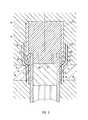
- FIG. 5is a cross sectional view of the high voltage connector of FIG. 4, illustrating electric fields associated with operation of the connector;
- FIG. 6is a cross sectional view illustrating various features of another embodiment of the present high voltage connector.
- FIGS. 1-6depict various features of embodiments of the present invention, which is generally directed to a high voltage connector having favorable electrical properties for avoiding electrical arcing within the connector.
- the high voltage connectoris utilized in connection with a high power device, such as an x-ray tube, though other high power devices can also benefit from the connector as taught herein.
- the present connectorenables an x-ray tube to operate at relatively higher operating voltages while controlling the incidence of electrical arcing within the connector. This, in turn, provides stability to the x-ray tube while operating at elevated voltages, allowing it to be utilized in a variety of high power applications, including explosives detection.
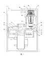
- FIG. 1illustrates in cross section a simplified structure of a rotating anode-type x-ray tube, designated generally at 10 .
- the present inventionis implemented in a pancake-style high voltage connector employed in connection with an x-ray tube, such as that depicted at 10 in FIG. 1 .
- the teachings hereincan also be applied to high voltage connectors utilized with other devices as well.
- the x-ray tube 10includes an outer housing 11 , within which is disposed an evacuated enclosure 12 . Disposed within the evacuated enclosure 12 are a rotating anode 14 and a cathode 16 . The anode 14 is spaced apart from and oppositely disposed to the cathode 16 , and is at least partially composed of a thermally conductive material such as tungsten or a molybdenum alloy. The anode 14 is rotatably supported by a rotor shaft 15 and a bearing assembly 17 .
- a high voltage potentialis provided between the anode 14 and cathode 16 .
- the cathode 16is biased by a power source (not shown) to have a large negative voltage, while the anode 14 is maintained at ground potential.
- the cathodeis biased with a negative voltage while the anode is biased with a positive voltage.
- X-ray tubesfeaturing either of these biasing configurations can utilize the present high voltage connector.
- the x-ray tube 10 illustrated in FIG. 1features a rotating anode, it is appreciated that stationary anode x-ray tubes can also benefit from the high voltage connector to be described herein.
- the cathode 16includes at least one filament 18 that is connected to an appropriate power source (not shown). During operation, an electrical current is passed through the filament 18 to cause electrons, designated at 20 , to be emitted from the cathode 16 by thermionic emission. Application of the high voltage differential between the anode 14 and the cathode 16 then causes the electrons 20 to accelerate from the cathode filament 18 toward a focal track 22 that is positioned on a target surface 24 of the rotating anode 14 .
- the focal track 22is typically composed of tungsten or a similar material having a high atomic (“high Z”) number.
- the electrons 20accelerate, they gain a substantial amount of kinetic energy, and upon striking the target material on the focal track 22 , some of this kinetic energy is converted into electromagnetic waves of very high frequency, i.e., x-rays.
- the emitted x-rays, designated at 26are directed through x-ray transmissive windows 28 and 30 disposed in the evacuated enclosure 12 and outer housing 11 , respectively.
- the windows 28 and 30are comprised of an x-ray transmissive material so as to enable the x-rays to pass through the windows and exit the tube 10 .
- the x-rays exiting the tubecan then be directed for penetration into an object, such as a patient's body during a medical evaluation, or a sample for purposes of materials analysis.
- the x-ray tube 10further includes a high voltage connector assembly, designated at 50 , which is operably connected to the cathode 16 , as seen in FIG. 1 .
- the high voltage connector 50is responsible for electrically coupling a high voltage cable 52 to the x-ray tube 10 .
- the high voltage cable 52is, in turn, connected to a high voltage power source (not shown).
- the high voltage connector 50via the high voltage cable 52 , facilitates the provision of an electrical voltage bias to the cathode 16 , as well as an electric current to the filament 18 during tube operation.
- the connector 50couples electrical components of the cathode 16 with the high voltage cable 52 , as explained more fully below.
- the high voltage connector 50generally comprises an outer connector housing 54 , a socket assembly 56 , and insulating material 58 .
- the connector housing 54in addition to housing the other components of the connector 50 , provides a mounting surface for attaching the connector to a portion of the cathode 16 via mechanical fasteners or other appropriate mode of attachment.
- the housing 54further defines a port 60 through which the high voltage cable 52 passes.
- the high voltage cable 52electrically connects with the socket assembly 56 within the housing 54 as described below.
- the socket assembly 56is disposed within a cavity 54 A defined by the housing 54 , and is centrally positioned on a bottom face 55 of the connector 50 so as facilitate electrical connection with corresponding components of the cathode 16 .
- the insulating material 58substantially fills the rest of the cavity 54 A to provide electrical isolation of the housing 54 from the socket assembly 56 .
- the insulating material 58in one embodiment, comprises an insulating epoxy.
- the socket assembly 56generally comprises a cylindrical, electrically conductive sleeve 70 , and a potting material 72 disposed within the sleeve.
- the cylindrical sleeve 70is configured to electrically connect with a portion of a cathode receptacle 80 to provide the cathode 16 with a proper voltage bias.
- the sleevepreferably comprises a metal, such as brass.
- the sleeve 70includes an annular terminal end 78 that is configured to prevent electrical arcing, in accordance with the present invention.
- the potting material 72comprises, in one embodiment, an insulating material, such as plastic epoxy or other appropriate material.
- a plurality of female sockets 74are disposed on the bottom face 55 of the connector 50 at a terminal end 72 A of the potting material 72 .
- Each socket 74is electrically connected to the high voltage cable 52 (see FIGS. 1 and 2 ), and is configured to electrically connect with corresponding terminals (not shown) disposed in the cathode 16 when the connector 50 is operably attached to the x-ray tube 10 .
- This interconnectionprovides an electric current to the one or more filaments 18 disposed in the cathode 16 , thereby enabling the filaments to produce electrons by thermionic emission.
- the sockets 74are electrically isolated from the sleeve 70 by the potting material 72 .
- four sockets 74are disposed at the terminal end 72 A, however, m or fewer sockets can be disposed therein.
- the sockets 74could alternatively comprise male electrical terminals or some other electrical connection configuration.
- a cylindrically shaped, annular gap 76is defined between the sleeve 70 and the potting material 72 at the terminal ends 72 A and 78 of the potting material 72 and the sleeve 70 , respectively.
- the gap 76is configured to receive therein a portion of the cathode receptacle 80 and provide a voltage bias to the cathode 16 during tube operation.
- the socket assembly 56further comprises means for electrically connecting the sleeve 70 to the cathode receptacle 80 .
- this functionis provided by structure comprising a conductive contact interposed between the sleeve 70 and the cathode receptacle 80 .
- the conductive contactcomprises a metal fingerstock ring 82 having a plurality of electrically conductive, resilient extensions 82 A.
- the fingerstock ring 82is disposed in an annular notch 84 defined on an inner surface of the sleeve 70 near the terminal end 78 of the sleeve.
- the fingerstock ring 82is configured to physically and electrically connect the sleeve 70 to the cathode receptacle 80 via the plurality of resilient extensions 82 A when the high voltage connector 50 is attached to the cathode 16 , as described further below. This enables the cathode receptacle 80 to be electrically charged for proper cathode operation.
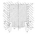
- the terminal end 78 of the sleeve 70is substantially enveloped by the insulating material 58 of the connector 50 .
- a triple junction 86is formed at the junction of the sleeve 70 , the insulating material 58 , and air present in the gap 76 .
- the terminal end 78 of the sleeve 70is further configured to advantageously prevent electrical arcing at the triple junction 86 .
- the terminal end 78 of the cylindrical sleeve 70is shaped to define a smooth, continuous surface.
- the terminal sleeve end 78defines an outwardly extending, rounded cross sectional shape having a radius “r.”
- the utility of the smoothly continuous shape of the terminal sleeve end 78 in reducing electrical arcing at or near the triple junction 86is explained further below in connection with FIG. 5 .
- the terminal end 78 of the sleeve 70can comprise other continuous cross sectional shapes as well.
- FIG. 4illustrates the interconnection of the present connector 50 with the cathode 16 .
- the cathode receptacle 80is received by the connector 50 into the gap 76 defined in the socket assembly 56 .
- Electrical connection between the cathode receptacle 80 and the cylindrical sleeve 70 of the socket assembly 56is established via the fingerstock ring 82 disposed in the notch 84 .
- the insertion of the cathode receptacle 80 into the gap 76causes the resilient extensions 82 A of the fingerstock ring 82 to deform and engage the surface of the receptacle.
- FIG. 4further illustrates an insulating gasket 88 that can be interposed between the cathode 16 and the connector 50 when the two are attached.
- the insulating gasket 88is annular and fits about a portion of the cathode receptacle 80 to further insulate the high voltage portions of the socket assembly 56 and cathode receptacle 80 from other portions of the x-ray tube 10 .
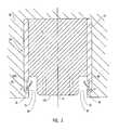
- FIG. 5illustrates the connection of the high voltage connector 50 to the cathode 16 , as shown in FIG. 4, with additional details.
- the socket assembly 56 of the connector 50is responsible for providing a negative voltage bias for the cathode 16 as well as providing an electrical signal for operation of one or more filaments 18 .
- the socket assembly 56is maintained at a high voltage during operation of the x-ray tube 10 .
- the high voltage that is present in and around the socket assembly 56 during tube operationis represented in FIG. 5 by electric field lines 90 .
- the continuously shaped terminal end 78 of the conductive socket assembly sleeve 70assists in preventing electrical arcing at or near the triple junction 86 formed at the meeting point of the terminal end of the conductive sleeve, the insulating material 58 , and air present in the gap 76 .
- the continuous surface defined by the terminal end 78 of the sleeve 70reduces arcing in at least two ways. First, and as can be seen in FIG. 5, the terminal end 78 , by virtue of its rounded shape, pushes the electric field away from the triple junction 86 .
- the high voltage connector 50can be used to maintain tube voltages at a higher level than what has been previously possible with known connectors.
- a high voltage connector of the present inventionwas able to maintain an operating x-ray tube voltage level of approximately 190 kV, significantly more than the typical 150 kV voltage limit.
- an x-ray tube utilizing a high voltage connector of the present inventionwas continuously run at an operating voltage level of 160 kV for several weeks without electrical arcing.
- the high voltage connector of the present inventionenables x-ray tubes to significantly expand the voltage levels at which they can operate.
- the higher voltage levels obtained by the present inventionallow for x-ray tubes to be utilized in specialized applications, such as explosives detection, where higher voltages are critical to ensuring adequate detection.
- x-ray tube operating at a voltage of 160 kVis able to detect explosives in luggage and other objects with a false-positive rate of less than one percent.
- a lower powered x-ray tube operating at only 150 kVcan have a false-positive rate of 2% or more.
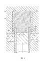
- a high voltage connector 150includes a socket assembly 156 disposed therein.
- the socket assembly 150includes a cylindrical sleeve 170 having an annular terminal end 178 .
- the terminal end 178defines a continuously shaped surface.
- the cross sectional shape of the terminal end 178is parabolic in the present embodiment and meets with insulating material 158 and air disposed in a gap 176 to form a triple junction 186 .
- the continuous cross sectional shape of the terminal end 178 of the sleeve 170prevents electrical arcing at the triple junction 186 during tube operation in the same manner as in the previous embodiment, that is, it operates to distance the electric field from the triple junction 186 to reduce the field strength along the conductive surface of the sleeve 170 near the terminal end 178 . Additionally, the triple junction 186 is characterized by the absence of sharp edges, which would otherwise increase the likelihood for arcing.
- the terminal end of the sleeve in the embodiments described hereincan be varied in cross sectional shape while still performing its intended function.
- the cross sectional shape of the terminal end of the sleevecan define a circular, parabolic, elliptical, or other continuous surface.
- the shape defined by the terminal end of the sleeveis characterized by a smooth and continuous surface having no sharp edges.
- the surfaceshould be defined such that it causes the electric field to be reduced in strength at any triple junction that is formed in part by the terminal end.
- terminal end shapes other than those described or illustrated hereinare also appreciated as falling within the present invention.
- the socket assembly 156 shown in FIG. 6further includes another example of a means for electrically connecting the sleeve 170 to a cathode receptacle (not shown).
- this functionis provided by structure comprising an electrically conductive O-ring interposed between the sleeve 170 and the cathode receptacle.
- the O-ring 182can be disposed in an annular notch 184 defined on an inner surface of the sleeve 170 , though other configurations are also possible.
- the O-ring 182Upon insertion of the cathode receptacle (not shown) into the gap 176 of the socket assembly 156 , the O-ring 182 establishes both physical and electrical contact between the sleeve 170 and the receptacle. As before, this enables electrical conductivity to the cathode of the x-ray tube to be established.
- the O-ring 182can be comprised of one or more of a variety of conductive materials, including metal.
Landscapes
- X-Ray Techniques (AREA)
- Connector Housings Or Holding Contact Members (AREA)
Abstract
Description
Claims (28)
Priority Applications (6)
| Application Number | Priority Date | Filing Date | Title |
|---|---|---|---|
| US10/213,624US6816574B2 (en) | 2002-08-06 | 2002-08-06 | X-ray tube high voltage connector |
| JP2004526459AJP2005535090A (en) | 2002-08-06 | 2003-08-05 | X-ray tube high voltage connector |
| PCT/US2003/024487WO2004013883A2 (en) | 2002-08-06 | 2003-08-05 | X-ray tube high voltage connector |
| AU2003273229AAU2003273229A1 (en) | 2002-08-06 | 2003-08-05 | X-ray tube high voltage connector |
| EP03755735AEP1540691A2 (en) | 2002-08-06 | 2003-08-05 | X-ray tube high voltage connector |
| US10/982,566US7033192B2 (en) | 2002-08-06 | 2004-11-05 | X-ray tube high voltage connector |
Applications Claiming Priority (1)
| Application Number | Priority Date | Filing Date | Title |
|---|---|---|---|
| US10/213,624US6816574B2 (en) | 2002-08-06 | 2002-08-06 | X-ray tube high voltage connector |
Related Child Applications (1)
| Application Number | Title | Priority Date | Filing Date |
|---|---|---|---|
| US10/982,566DivisionUS7033192B2 (en) | 2002-08-06 | 2004-11-05 | X-ray tube high voltage connector |
Publications (2)
| Publication Number | Publication Date |
|---|---|
| US20040028184A1 US20040028184A1 (en) | 2004-02-12 |
| US6816574B2true US6816574B2 (en) | 2004-11-09 |
Family
ID=31494490
Family Applications (2)
| Application Number | Title | Priority Date | Filing Date |
|---|---|---|---|
| US10/213,624Expired - Fee RelatedUS6816574B2 (en) | 2002-08-06 | 2002-08-06 | X-ray tube high voltage connector |
| US10/982,566Expired - Fee RelatedUS7033192B2 (en) | 2002-08-06 | 2004-11-05 | X-ray tube high voltage connector |
Family Applications After (1)
| Application Number | Title | Priority Date | Filing Date |
|---|---|---|---|
| US10/982,566Expired - Fee RelatedUS7033192B2 (en) | 2002-08-06 | 2004-11-05 | X-ray tube high voltage connector |
Country Status (5)
| Country | Link |
|---|---|
| US (2) | US6816574B2 (en) |
| EP (1) | EP1540691A2 (en) |
| JP (1) | JP2005535090A (en) |
| AU (1) | AU2003273229A1 (en) |
| WO (1) | WO2004013883A2 (en) |
Cited By (5)
| Publication number | Priority date | Publication date | Assignee | Title |
|---|---|---|---|---|
| US20050064750A1 (en)* | 2002-08-06 | 2005-03-24 | Wayne Hansen | X-ray tube high voltage connector |
| US20050233627A1 (en)* | 2004-04-16 | 2005-10-20 | Varian Medical Systems Technologies, Inc. | High voltage cable assembly with ARC protection |
| US20060050853A1 (en)* | 2004-09-09 | 2006-03-09 | Hansen Wayne R | High voltage cable terminal and clamp system |
| US7020244B1 (en) | 2004-12-17 | 2006-03-28 | General Electric Company | Method and design for electrical stress mitigation in high voltage insulators in X-ray tubes |
| US20190013174A1 (en)* | 2015-12-25 | 2019-01-10 | Nikon Corporation | Charged particle device, structure manufacturing method, and structure manufacturing system |
Families Citing this family (67)
| Publication number | Priority date | Publication date | Assignee | Title |
|---|---|---|---|---|
| US6922463B2 (en)* | 2002-11-14 | 2005-07-26 | Ge Medical Systems Global Technology Company, Llc | Thermally high conductive HV connector for a mono-polar CT tube |
| US6901136B1 (en)* | 2003-12-02 | 2005-05-31 | Ge Medical Systems Global Technology Co., Llc | X-ray tube system and apparatus with conductive proximity between cathode and electromagnetic shield |
| WO2005107021A1 (en)* | 2004-04-29 | 2005-11-10 | Philips Intellectual Property & Standards Gmbh | High-voltage connector |
| US8157589B2 (en) | 2004-11-24 | 2012-04-17 | John Mezzalingua Associates, Inc. | Connector having a conductively coated member and method of use thereof |
| US20060110977A1 (en) | 2004-11-24 | 2006-05-25 | Roger Matthews | Connector having conductive member and method of use thereof |
| US7114990B2 (en) | 2005-01-25 | 2006-10-03 | Corning Gilbert Incorporated | Coaxial cable connector with grounding member |
| AU2006306196C1 (en)* | 2005-10-27 | 2012-11-01 | Avery Dennison Corporation | Fluorescent article having multiple layers |
| WO2008008706A2 (en)* | 2006-07-10 | 2008-01-17 | Visual Graphic Systems Inc. | Support device for electrified sign insert |
| US7553080B2 (en) | 2007-02-07 | 2009-06-30 | Grady John K | Grounded rotating anode x-ray tube housing |
| US8284899B2 (en)* | 2007-11-21 | 2012-10-09 | Varian Medical Systems, Inc. | X-ray tube having a focal spot proximate the tube end |
| TWI352463B (en)* | 2008-01-23 | 2011-11-11 | Waterproof connector and method for the same | |
| US8025518B2 (en) | 2009-02-24 | 2011-09-27 | Corning Gilbert Inc. | Coaxial connector with dual-grip nut |
| US8029315B2 (en) | 2009-04-01 | 2011-10-04 | John Mezzalingua Associates, Inc. | Coaxial cable connector with improved physical and RF sealing |
| US7824216B2 (en) | 2009-04-02 | 2010-11-02 | John Mezzalingua Associates, Inc. | Coaxial cable continuity connector |
| US7892005B2 (en) | 2009-05-19 | 2011-02-22 | John Mezzalingua Associates, Inc. | Click-tight coaxial cable continuity connector |
| US8573996B2 (en) | 2009-05-22 | 2013-11-05 | Ppc Broadband, Inc. | Coaxial cable connector having electrical continuity member |
| US9570845B2 (en) | 2009-05-22 | 2017-02-14 | Ppc Broadband, Inc. | Connector having a continuity member operable in a radial direction |
| US8444445B2 (en) | 2009-05-22 | 2013-05-21 | Ppc Broadband, Inc. | Coaxial cable connector having electrical continuity member |
| US8287320B2 (en) | 2009-05-22 | 2012-10-16 | John Mezzalingua Associates, Inc. | Coaxial cable connector having electrical continuity member |
| US9017101B2 (en) | 2011-03-30 | 2015-04-28 | Ppc Broadband, Inc. | Continuity maintaining biasing member |
| US8272893B2 (en) | 2009-11-16 | 2012-09-25 | Corning Gilbert Inc. | Integrally conductive and shielded coaxial cable connector |
| TWI549386B (en) | 2010-04-13 | 2016-09-11 | 康寧吉伯特公司 | Coaxial connector with inhibited ingress and improved grounding |
| US8079860B1 (en) | 2010-07-22 | 2011-12-20 | John Mezzalingua Associates, Inc. | Cable connector having threaded locking collet and nut |
| US8152551B2 (en) | 2010-07-22 | 2012-04-10 | John Mezzalingua Associates, Inc. | Port seizing cable connector nut and assembly |
| US8113879B1 (en) | 2010-07-27 | 2012-02-14 | John Mezzalingua Associates, Inc. | One-piece compression connector body for coaxial cable connector |
| US8888526B2 (en) | 2010-08-10 | 2014-11-18 | Corning Gilbert, Inc. | Coaxial cable connector with radio frequency interference and grounding shield |
| US8167636B1 (en) | 2010-10-15 | 2012-05-01 | John Mezzalingua Associates, Inc. | Connector having a continuity member |
| US8167635B1 (en) | 2010-10-18 | 2012-05-01 | John Mezzalingua Associates, Inc. | Dielectric sealing member and method of use thereof |
| US8167646B1 (en) | 2010-10-18 | 2012-05-01 | John Mezzalingua Associates, Inc. | Connector having electrical continuity about an inner dielectric and method of use thereof |
| US8323053B2 (en) | 2010-10-18 | 2012-12-04 | John Mezzalingua Associates, Inc. | Connector having a constant contact nut |
| US8075338B1 (en) | 2010-10-18 | 2011-12-13 | John Mezzalingua Associates, Inc. | Connector having a constant contact post |
| TWI558022B (en) | 2010-10-27 | 2016-11-11 | 康寧吉伯特公司 | Push-on cable connector with a coupler and retention and release mechanism |
| US8337229B2 (en) | 2010-11-11 | 2012-12-25 | John Mezzalingua Associates, Inc. | Connector having a nut-body continuity element and method of use thereof |
| US8414322B2 (en) | 2010-12-14 | 2013-04-09 | Ppc Broadband, Inc. | Push-on CATV port terminator |
| US8398421B2 (en) | 2011-02-01 | 2013-03-19 | John Mezzalingua Associates, Inc. | Connector having a dielectric seal and method of use thereof |
| US8465322B2 (en) | 2011-03-25 | 2013-06-18 | Ppc Broadband, Inc. | Coaxial cable connector |
| US8342879B2 (en) | 2011-03-25 | 2013-01-01 | John Mezzalingua Associates, Inc. | Coaxial cable connector |
| US8366481B2 (en) | 2011-03-30 | 2013-02-05 | John Mezzalingua Associates, Inc. | Continuity maintaining biasing member |
| US8388377B2 (en) | 2011-04-01 | 2013-03-05 | John Mezzalingua Associates, Inc. | Slide actuated coaxial cable connector |
| US8675818B2 (en) | 2011-04-12 | 2014-03-18 | Varian Medical Systems, Inc. | Ceramic metallization in an x-ray tube |
| US8348697B2 (en) | 2011-04-22 | 2013-01-08 | John Mezzalingua Associates, Inc. | Coaxial cable connector having slotted post member |
| US9203167B2 (en) | 2011-05-26 | 2015-12-01 | Ppc Broadband, Inc. | Coaxial cable connector with conductive seal |
| US9711917B2 (en) | 2011-05-26 | 2017-07-18 | Ppc Broadband, Inc. | Band spring continuity member for coaxial cable connector |
| US8758050B2 (en) | 2011-06-10 | 2014-06-24 | Hiscock & Barclay LLP | Connector having a coupling member for locking onto a port and maintaining electrical continuity |
| US8591244B2 (en) | 2011-07-08 | 2013-11-26 | Ppc Broadband, Inc. | Cable connector |
| US9190744B2 (en) | 2011-09-14 | 2015-11-17 | Corning Optical Communications Rf Llc | Coaxial cable connector with radio frequency interference and grounding shield |
| US20130072057A1 (en) | 2011-09-15 | 2013-03-21 | Donald Andrew Burris | Coaxial cable connector with integral radio frequency interference and grounding shield |
| US9147955B2 (en) | 2011-11-02 | 2015-09-29 | Ppc Broadband, Inc. | Continuity providing port |
| US9136654B2 (en) | 2012-01-05 | 2015-09-15 | Corning Gilbert, Inc. | Quick mount connector for a coaxial cable |
| US9407016B2 (en) | 2012-02-22 | 2016-08-02 | Corning Optical Communications Rf Llc | Coaxial cable connector with integral continuity contacting portion |
| US9287659B2 (en) | 2012-10-16 | 2016-03-15 | Corning Optical Communications Rf Llc | Coaxial cable connector with integral RFI protection |
| US9147963B2 (en) | 2012-11-29 | 2015-09-29 | Corning Gilbert Inc. | Hardline coaxial connector with a locking ferrule |
| US9153911B2 (en) | 2013-02-19 | 2015-10-06 | Corning Gilbert Inc. | Coaxial cable continuity connector |
| US9172154B2 (en) | 2013-03-15 | 2015-10-27 | Corning Gilbert Inc. | Coaxial cable connector with integral RFI protection |
| US10290958B2 (en) | 2013-04-29 | 2019-05-14 | Corning Optical Communications Rf Llc | Coaxial cable connector with integral RFI protection and biasing ring |
| CN105284015B (en) | 2013-05-20 | 2019-03-08 | 康宁光电通信Rf有限责任公司 | Coaxial cable connector with whole RFI protection |
| US9548557B2 (en) | 2013-06-26 | 2017-01-17 | Corning Optical Communications LLC | Connector assemblies and methods of manufacture |
| US9048599B2 (en) | 2013-10-28 | 2015-06-02 | Corning Gilbert Inc. | Coaxial cable connector having a gripping member with a notch and disposed inside a shell |
| WO2016073309A1 (en) | 2014-11-03 | 2016-05-12 | Corning Optical Communications Rf Llc | Coaxial cable connector with integral rfi protection |
| US10033122B2 (en) | 2015-02-20 | 2018-07-24 | Corning Optical Communications Rf Llc | Cable or conduit connector with jacket retention feature |
| US9590287B2 (en) | 2015-02-20 | 2017-03-07 | Corning Optical Communications Rf Llc | Surge protected coaxial termination |
| US10211547B2 (en) | 2015-09-03 | 2019-02-19 | Corning Optical Communications Rf Llc | Coaxial cable connector |
| US9525220B1 (en) | 2015-11-25 | 2016-12-20 | Corning Optical Communications LLC | Coaxial cable connector |
| US11574789B2 (en)* | 2017-01-26 | 2023-02-07 | Varex Imaging Corporation | Electrical connectors for multiple emitter cathodes |
| US10186799B2 (en)* | 2017-02-21 | 2019-01-22 | The Boeing Company | Electrical connectors having field shaping rings |
| EP3419042A1 (en)* | 2017-06-23 | 2018-12-26 | Koninklijke Philips N.V. | X-ray tube insulator |
| US12034264B2 (en) | 2021-03-31 | 2024-07-09 | Corning Optical Communications Rf Llc | Coaxial cable connector assemblies with outer conductor engagement features and methods for using the same |
Citations (3)
| Publication number | Priority date | Publication date | Assignee | Title |
|---|---|---|---|---|
| US4799248A (en)* | 1987-08-06 | 1989-01-17 | Picker International, Inc. | X-ray tube having multiple cathode filaments |
| US4806113A (en)* | 1986-01-03 | 1989-02-21 | General Electric Company | High voltage connector for x-ray equipment |
| US6213805B1 (en)* | 1997-10-09 | 2001-04-10 | Hans Jedlitschka | Boot/ring for high voltage connector and high-voltage connector obtained |
Family Cites Families (29)
| Publication number | Priority date | Publication date | Assignee | Title |
|---|---|---|---|---|
| DE1564769B1 (en)* | 1965-12-06 | 1971-03-25 | Kunio Shimizu | Device for giving an electric shock to the human body |
| US3888559A (en)* | 1972-04-13 | 1975-06-10 | Amp Inc | High voltage quick disconnect assembly |
| US3803463A (en)* | 1972-07-10 | 1974-04-09 | J Cover | Weapon for immobilization and capture |
| US3904264A (en)* | 1974-03-04 | 1975-09-09 | Continental Oil Co | Electrical connector |
| US4335928A (en)* | 1980-06-30 | 1982-06-22 | General Electric Company | High voltage connector for x-ray equipment |
| US4362348A (en)* | 1980-07-03 | 1982-12-07 | Automation Industries, Inc. | EMI: X-Ray protected multi-contact connector |
| US4494811A (en)* | 1980-12-10 | 1985-01-22 | Picker Corporation | High voltage connector assembly with internal oil expansion chamber |
| US4767961A (en)* | 1981-02-17 | 1988-08-30 | The Machlett Laboratories, Inc. | X-ray generator cooling system |
| FR2655209B1 (en)* | 1989-11-24 | 1992-02-14 | Gen Electric Cgr | HIGH VOLTAGE CONNECTOR FOR X-RAY TUBE. |
| US5145402A (en)* | 1990-06-06 | 1992-09-08 | General Motors Corporation | Electrical connector |
| US5162267A (en)* | 1991-09-27 | 1992-11-10 | Smyth Milagros B | Radio-opaque calcium phosphate glass |
| US5384820A (en)* | 1992-01-06 | 1995-01-24 | Picker International, Inc. | Journal bearing and radiation shield for rotating housing and anode/stationary cathode X-ray tubes |
| US5310361A (en)* | 1992-11-30 | 1994-05-10 | Eureka X-Ray Tube Corp. | High-voltage x-ray cable connection |
| US5358419A (en)* | 1993-08-30 | 1994-10-25 | General Electric Company | Electrical power tube connector |
| US5553114A (en) | 1994-04-04 | 1996-09-03 | General Electric Company | Emissive coating for X-ray tube rotors |
| US5473501A (en)* | 1994-03-30 | 1995-12-05 | Claypool; James P. | Long range electrical stun gun |
| US5654867A (en)* | 1994-09-09 | 1997-08-05 | Barnet Resnick | Immobilization weapon |
| US5707252A (en) | 1995-10-10 | 1998-01-13 | Alden Products Company | Snap-together x-ray cable coupling nut assembly |
| US5750918A (en)* | 1995-10-17 | 1998-05-12 | Foster-Miller, Inc. | Ballistically deployed restraining net |
| US5698815A (en)* | 1995-12-15 | 1997-12-16 | Ragner; Gary Dean | Stun bullets |
| US5786546A (en)* | 1996-08-29 | 1998-07-28 | Simson; Anton K. | Stungun cartridge |
| US5962806A (en)* | 1996-11-12 | 1999-10-05 | Jaycor | Non-lethal projectile for delivering an electric shock to a living target |
| US5831199A (en)* | 1997-05-29 | 1998-11-03 | James McNulty, Jr. | Weapon for immobilization and capture |
| CA2269918A1 (en) | 1998-04-27 | 1999-10-27 | Robert K. Sheehan | Safety lock conduit connector |
| US6198802B1 (en) | 1998-10-06 | 2001-03-06 | Cardiac Mariners, Inc. | Scanning beam x-ray source and assembly |
| US6636412B2 (en)* | 1999-09-17 | 2003-10-21 | Taser International, Inc. | Hand-held stun gun for incapacitating a human target |
| US6556654B1 (en)* | 2001-11-09 | 2003-04-29 | Varian Medical Systems, Inc. | High voltage cable and clamp system for an X-ray tube |
| US6679180B2 (en)* | 2001-11-21 | 2004-01-20 | Southwest Research Institute | Tetherless neuromuscular disrupter gun with liquid-based capacitor projectile |
| US6816574B2 (en)* | 2002-08-06 | 2004-11-09 | Varian Medical Systems, Inc. | X-ray tube high voltage connector |
- 2002
- 2002-08-06USUS10/213,624patent/US6816574B2/ennot_activeExpired - Fee Related
- 2003
- 2003-08-05EPEP03755735Apatent/EP1540691A2/ennot_activeWithdrawn
- 2003-08-05WOPCT/US2003/024487patent/WO2004013883A2/ennot_activeApplication Discontinuation
- 2003-08-05AUAU2003273229Apatent/AU2003273229A1/ennot_activeAbandoned
- 2003-08-05JPJP2004526459Apatent/JP2005535090A/enactivePending
- 2004
- 2004-11-05USUS10/982,566patent/US7033192B2/ennot_activeExpired - Fee Related
Patent Citations (3)
| Publication number | Priority date | Publication date | Assignee | Title |
|---|---|---|---|---|
| US4806113A (en)* | 1986-01-03 | 1989-02-21 | General Electric Company | High voltage connector for x-ray equipment |
| US4799248A (en)* | 1987-08-06 | 1989-01-17 | Picker International, Inc. | X-ray tube having multiple cathode filaments |
| US6213805B1 (en)* | 1997-10-09 | 2001-04-10 | Hans Jedlitschka | Boot/ring for high voltage connector and high-voltage connector obtained |
Cited By (9)
| Publication number | Priority date | Publication date | Assignee | Title |
|---|---|---|---|---|
| US20050064750A1 (en)* | 2002-08-06 | 2005-03-24 | Wayne Hansen | X-ray tube high voltage connector |
| US7033192B2 (en)* | 2002-08-06 | 2006-04-25 | Varian Medical Systems, Inc. | X-ray tube high voltage connector |
| US20050233627A1 (en)* | 2004-04-16 | 2005-10-20 | Varian Medical Systems Technologies, Inc. | High voltage cable assembly with ARC protection |
| US7445517B2 (en) | 2004-04-16 | 2008-11-04 | Varian Medical Systems, Inc. | High voltage cable assembly with ARC protection |
| US20060050853A1 (en)* | 2004-09-09 | 2006-03-09 | Hansen Wayne R | High voltage cable terminal and clamp system |
| US7150562B2 (en) | 2004-09-09 | 2006-12-19 | Finisar Corporation | High voltage cable terminal and clamp system |
| US7020244B1 (en) | 2004-12-17 | 2006-03-28 | General Electric Company | Method and design for electrical stress mitigation in high voltage insulators in X-ray tubes |
| US20190013174A1 (en)* | 2015-12-25 | 2019-01-10 | Nikon Corporation | Charged particle device, structure manufacturing method, and structure manufacturing system |
| US10879029B2 (en)* | 2015-12-25 | 2020-12-29 | Nikon Corporation | Charged particle device, structure manufacturing method, and structure manufacturing system |
Also Published As
| Publication number | Publication date |
|---|---|
| US7033192B2 (en) | 2006-04-25 |
| AU2003273229A8 (en) | 2004-02-23 |
| US20040028184A1 (en) | 2004-02-12 |
| AU2003273229A1 (en) | 2004-02-23 |
| WO2004013883A3 (en) | 2004-09-02 |
| US20050064750A1 (en) | 2005-03-24 |
| EP1540691A2 (en) | 2005-06-15 |
| WO2004013883A2 (en) | 2004-02-12 |
| JP2005535090A (en) | 2005-11-17 |
Similar Documents
| Publication | Publication Date | Title |
|---|---|---|
| US6816574B2 (en) | X-ray tube high voltage connector | |
| US7702077B2 (en) | Apparatus for a compact HV insulator for x-ray and vacuum tube and method of assembling same | |
| US10880978B2 (en) | Bipolar X-ray module | |
| US6134300A (en) | Miniature x-ray source | |
| EP2179436B1 (en) | Compact high voltage x-ray source system and method for x-ray inspection applications | |
| EP2697814B1 (en) | Metalized ceramic sealing plate for an x-ray tube | |
| US6798865B2 (en) | HV system for a mono-polar CT tube | |
| US8379799B2 (en) | Electrically insulating X-ray shielding devices in an X-ray tube | |
| US20040096037A1 (en) | Thermally high conductive HV connector for a mono-polar CT tube | |
| US11147148B2 (en) | X-ray generator | |
| JP4768253B2 (en) | X-ray tube system and apparatus having conductive proximity between cathode and electromagnetic shield | |
| CN106376166B (en) | High voltage source for x-ray emission device | |
| CN115988728A (en) | Neutron generator | |
| CN111554556B (en) | X-ray tube and medical imaging apparatus | |
| US12283452B2 (en) | Charged particle beam apparatus | |
| US20070291903A1 (en) | Integral x-ray tube shielding for high-voltage x-ray tube cables | |
| US7197114B2 (en) | X-rays emitter and X-ray apparatus and method of manufacturing an X-ray emitter | |
| US11139139B2 (en) | Charged particle beam generator and charged particle beam apparatus | |
| RU2248643C1 (en) | X-ray tube with field-radiating cathode | |
| JPH0272516A (en) | Bushing for high voltage | |
| CN223110225U (en) | Radiation source device and detection equipment | |
| US20200335296A1 (en) | Reflection type x-ray tube | |
| JPS631699B2 (en) | ||
| Zucarias et al. | X-ray generator | |
| KR20010046435A (en) | Cathode ray tube |
Legal Events
| Date | Code | Title | Description |
|---|---|---|---|
| AS | Assignment | Owner name:VARIAN MEDICAL SYSTEMS, INC., CALIFORNIA Free format text:ASSIGNMENT OF ASSIGNORS INTEREST;ASSIGNOR:HANSEN, WAYNE;REEL/FRAME:013182/0510 Effective date:20020731 | |
| AS | Assignment | Owner name:VARIAN MEDICAL SYSTEMS TECHNOLOGIES, INC., CALIFOR Free format text:ASSIGNMENT OF ASSIGNORS INTEREST;ASSIGNOR:VARIAN MEDICAL SYSTEMS, INC.;REEL/FRAME:014555/0199 Effective date:20030925 | |
| AS | Assignment | Owner name:VARIAN MEDICAL SYSTEMS TECHNOLOGIES, INC., CALIFOR Free format text:ASSIGNMENT OF ASSIGNORS INTEREST;ASSIGNOR:VARIAN MEDICAL SYSTEMS, INC.;REEL/FRAME:016862/0513 Effective date:20030925 | |
| FPAY | Fee payment | Year of fee payment:4 | |
| AS | Assignment | Owner name:VARIAN MEDICAL SYSTEMS, INC., CALIFORNIA Free format text:MERGER;ASSIGNOR:VARIAN MEDICAL SYSTEMS TECHNOLOGIES, INC.;REEL/FRAME:021669/0669 Effective date:20080926 | |
| CC | Certificate of correction | ||
| FPAY | Fee payment | Year of fee payment:8 | |
| REMI | Maintenance fee reminder mailed | ||
| LAPS | Lapse for failure to pay maintenance fees | ||
| STCH | Information on status: patent discontinuation | Free format text:PATENT EXPIRED DUE TO NONPAYMENT OF MAINTENANCE FEES UNDER 37 CFR 1.362 | |
| FP | Lapsed due to failure to pay maintenance fee | Effective date:20161109 |