US6815002B2 - Method for dispensing liquid crystal using plurality of liquid crystal dispensing devices - Google Patents
Method for dispensing liquid crystal using plurality of liquid crystal dispensing devicesDownload PDFInfo
- Publication number
- US6815002B2 US6815002B2US10/184,084US18408402AUS6815002B2US 6815002 B2US6815002 B2US 6815002B2US 18408402 AUS18408402 AUS 18408402AUS 6815002 B2US6815002 B2US 6815002B2
- Authority
- US
- United States
- Prior art keywords
- liquid crystal
- substrate
- dispensing devices
- column
- onto
- Prior art date
- Legal status (The legal status is an assumption and is not a legal conclusion. Google has not performed a legal analysis and makes no representation as to the accuracy of the status listed.)
- Expired - Lifetime, expires
Links
Images


Classifications
- H—ELECTRICITY
- H01—ELECTRIC ELEMENTS
- H01L—SEMICONDUCTOR DEVICES NOT COVERED BY CLASS H10
- H01L21/00—Processes or apparatus adapted for the manufacture or treatment of semiconductor or solid state devices or of parts thereof
- H01L21/67—Apparatus specially adapted for handling semiconductor or electric solid state devices during manufacture or treatment thereof; Apparatus specially adapted for handling wafers during manufacture or treatment of semiconductor or electric solid state devices or components ; Apparatus not specifically provided for elsewhere
- H01L21/67005—Apparatus not specifically provided for elsewhere
- H01L21/67011—Apparatus for manufacture or treatment
- H01L21/6715—Apparatus for applying a liquid, a resin, an ink or the like
- G—PHYSICS
- G02—OPTICS
- G02F—OPTICAL DEVICES OR ARRANGEMENTS FOR THE CONTROL OF LIGHT BY MODIFICATION OF THE OPTICAL PROPERTIES OF THE MEDIA OF THE ELEMENTS INVOLVED THEREIN; NON-LINEAR OPTICS; FREQUENCY-CHANGING OF LIGHT; OPTICAL LOGIC ELEMENTS; OPTICAL ANALOGUE/DIGITAL CONVERTERS
- G02F1/00—Devices or arrangements for the control of the intensity, colour, phase, polarisation or direction of light arriving from an independent light source, e.g. switching, gating or modulating; Non-linear optics
- G02F1/01—Devices or arrangements for the control of the intensity, colour, phase, polarisation or direction of light arriving from an independent light source, e.g. switching, gating or modulating; Non-linear optics for the control of the intensity, phase, polarisation or colour
- G02F1/13—Devices or arrangements for the control of the intensity, colour, phase, polarisation or direction of light arriving from an independent light source, e.g. switching, gating or modulating; Non-linear optics for the control of the intensity, phase, polarisation or colour based on liquid crystals, e.g. single liquid crystal display cells
- G02F1/133—Constructional arrangements; Operation of liquid crystal cells; Circuit arrangements
- G02F1/1333—Constructional arrangements; Manufacturing methods
- G02F1/1341—Filling or closing of cells
- G02F1/13415—Drop filling process
Definitions
- the present inventionrelates to a method of dispensing liquid crystal. More particularly, the present invention relates to a method of dispensing liquid crystal from N liquid crystal dispensing devices onto M panel locations (where M>N) such that the amount of liquid crystal dispensed from each of the N liquid crystal dispensing devices over time is substantially the same.
- LCDsliquid crystal displays
- PDPplasma display panels
- FEDfield emission displays
- VFDvacuum fluorescent displays
- an LCD 1comprises a lower substrate 5 , an upper substrate 3 , and a liquid crystal layer 7 that is disposed between the lower substrate 5 and the upper substrate 3 .
- the lower substrate 5includes an array of driving devices and a plurality of pixels (not shown).
- the individual driving devicesare usually thin film transistors (TFT) located at each pixel.
- the upper substrate 3includes color filters for producing color.
- a pixel electrode and a common electrodeare respectively formed on the lower substrate 5 and on the upper substrate 3 .
- Alignment layersare formed on the lower substrate 5 and on the upper substrate 3 . The alignment layers are used to uniformly align the liquid crystal layer 7 .
- the lower substrate 5 and the upper substrate 3are attached using a sealing material 9 .
- the liquid crystal moleculesare initially oriented by the alignment layers, and then reoriented by the driving device according to video information so as to control the light transmitted through the liquid crystal layer to produce an image.
- the fabrication of an LCD devicerequires the forming of driving devices on the lower substrate 5 , the forming of the color filters on the upper substrate 3 , and performing a cell process (described subsequently). Those processes will be described with reference to FIG. 2 .
- step S 101a plurality of perpendicularly crossing gate lines and data lines are formed on the lower substrate 5 , thereby defining pixel areas between the gate and data lines.
- a thin film transistor that is connected to a gate line and to a data lineis formed in each pixel area.
- a pixel electrode that is connected to the thin film transistoris formed in each pixel area. This enables driving the liquid crystal layer according to signals applied through the thin film transistor.
- step S 104R (Red), G (Green), and B (Blue) color filter layers (for reproducing color) and a common electrode are formed on the upper substrate 3 .
- steps S 102 and S 105alignment layers are formed on the lower substrate 5 and on the upper substrate 3 .
- the alignment layersare rubbed to induce surface anchoring (establishing a pretilt angle and an alignment direction) for the liquid crystal molecules.
- step S 103spacers for maintaining a constant, uniform cell gap is dispersed onto the lower substrate 5 .
- steps S 106 and S 107a sealing material is applied onto outer portions such that the resulting seal has a liquid crystal injection opening. That opening is used to inject liquid crystal.
- the upper substrate 3 and the lower substrate 5are then attached together by compressing the sealing material.
- the lower substrate 5 and the upper substrate 3are large glass substrates that contain a plurality of unit panel areas, each having a driving device array or a color filter array surrounded by sealant having a liquid crystal injection opening.
- step S 108the assembled glass substrates are cut into individual unit panels.
- step S 109liquid crystal is injected into the individual unit panels by way of liquid crystal injection openings, which are then sealed.
- step S 110the individual unit panels are tested.
- FIG. 3shows a device for injecting liquid crystal.
- a container 12that contains liquid crystal, and a plurality of individual unit panels 1 are placed in a vacuum chamber 10 such that the individual unit panels 1 are located above the container 12 .
- the vacuum chamber 10is connected to a vacuum pump that produces a predetermined vacuum.
- a liquid crystal display panel moving device(not shown) moves the individual unit panels 1 into contact with the liquid crystal 14 such that each injection opening 16 is in the liquid crystal 14 .
- the liquid crystal 14When the vacuum within the chamber 10 is increased by inflowing nitrogen gas (N 2 ) the liquid crystal 14 is injected into the individual unit panels 1 through the liquid crystal injection openings 16 . After the liquid crystal 14 entirely fills the individual unit panels 1 , the liquid crystal injection opening 16 of each individual unit panel 1 is sealed by a sealing material.
- N 2nitrogen gas
- liquid crystal 14 consumptionis excessive. Only a small amount of liquid crystal 14 in the container 12 is actually injected into the individual unit panels 1 . Since liquid crystal 14 exposed to air or to certain other gases can be contaminated by chemical reaction the remaining liquid crystal 14 should be discarded. This increases liquid crystal fabrication costs.
- a method of disposing liquid crystal between substrates using a plurality of liquid crystal dispensing deviceswould be beneficial. Even more beneficial would be a method of using N liquid crystal dispensing devices to disposing liquid crystal on M substrate locations, wherein M>N, such that the amount of liquid crystal dispensed from each of the N liquid crystal dispensing devices over time is substantially the same.
- the present inventionis directed to provide a method for dispensing liquid crystal that enables increased efficiency and reduced liquid crystal consumption by applying liquid crystal from a plurality of liquid crystal dispensing devices onto a plurality of liquid crystal panels that substantially obviates one or more of the problems due to limitations and disadvantages of the related art.
- Another advantage of the present inventionis to provide a method of dispensing liquid crystal from N liquid crystal dispensing devices onto M panel areas, wherein M>N, such that each liquid crystal dispensing device applies substantially the same amount of liquid crystal over time. This beneficially reduces refilling, cleaning, and set-up problems associated with refilling liquid crystal into the liquid crystal containers.
- a method for dispensing liquid crystalwherein liquid crystal is applied onto a substrate on which a plurality of liquid crystal panel columns are disposed using a plurality of liquid crystal dispensing devices.
- the plurality of liquid crystal dispensing devicesapply liquid crystal onto a plurality of liquid crystal panel columns, except onto a first column.
- a first liquid crystal dispensing device of the plurality of liquid crystal dispensing devicessubsequently applies liquid crystal onto the first column.
- the plurality of liquid crystal dispensing devicesthen apply liquid crystal onto a plurality of liquid crystal panel columns of a second substrate, except onto a second column. Then, liquid crystal is applied onto the second column using a second liquid crystal dispensing device of the plurality of liquid crystal dispensing devices.
- the principles of the present inventionfurther provide for a method of applying liquid crystals from N liquid crystal dispensing devices onto a plurality of substrates, each substrate having a plurality of liquid crystal panels aligned in M columns, wherein M is greater than N. That method includes applying liquid crystals from the N liquid crystal dispensing devices onto the liquid crystal panels in N columns of a first substrate. Then, applying liquid crystals onto the liquid crystal panels of an N+1th column of the first substrate using a first liquid crystal dispensing device of the N liquid crystal dispensing devices. Then, applying liquid crystals from the N liquid crystal dispensing devices onto the liquid crystal panels in N columns of a second substrate. Finally, applying liquid crystals onto the liquid crystal panels of an N+1th column of the second substrate using a second liquid crystal dispensing device of the N liquid crystal dispensing devices.
- the principles of the present inventionfurther provide for applying liquid crystals from the N liquid crystal dispensing devices onto the liquid crystal panels in N columns of a third substrate, and then applying liquid crystals onto the liquid crystal panels of an N+1th column of the third substrate using a third liquid crystal dispensing device of the N liquid crystal dispensing devices. Furthermore, the principles of the present invention provide for applying liquid crystals from the N liquid crystal dispensing devices onto the liquid crystal panels in N columns of a fourth substrate, and then applying liquid crystals onto the liquid crystal panels of an N+1th column of the fourth substrate using a fourth liquid crystal dispensing device of the N liquid crystal dispensing devices.
- FIG. 1is a cross-sectional view showing a general LCD
- FIG. 2is a flow chart showing a conventional method for fabricating the LCD
- FIG. 3is a view showing liquid crystal injection in the conventional method for fabricating the LCD
- FIG. 4is a view showing an exemplary LCD fabricated using a method for dropping liquid crystal according to the present invention
- FIG. 5is a flow chart showing an exemplary method for fabricating the LCD according to the liquid crystal dropping method
- FIG. 6is a view showing the basic concept of the liquid crystal dropping method
- FIG. 7Aillustrates a state in which liquid crystal is not dropped from a liquid crystal dropping apparatus
- FIG. 7Billustrates a state in which liquid crystal is being dropped from a liquid crystal dropping apparatus
- FIG. 8illustrates dropping liquid crystal onto a substrate having 4 columns of liquid crystal panel areas using four liquid crystal dispensing devices
- FIG. 9illustrates dropping liquid crystal onto a substrate having 5 columns of liquid crystal panel areas using four liquid crystal dispensing devices
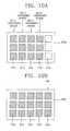
- FIGS. 10A and 10Billustrate dropping liquid crystal onto the liquid crystal panel area disposed on a first substrate according to the principles of the present invention
- FIGS. 11A and 11Billustrate dropping liquid crystal onto the liquid crystal panel area disposed on a second substrate according to the principles of the present invention.
- FIGS. 12A and 12Billustrate dropping liquid crystal onto the liquid crystal panel areas disposed on a third and a fourth substrate according to the principles of the present invention.
- the liquid crystal dropping methodforms a liquid crystal layer by directly applying liquid crystal onto a substrate and then spreading the applied liquid crystal by pressing substrates together. According to the liquid crystal dropping method, the liquid crystal is applied to the substrate in a short time period such that the liquid crystal layer can be formed quickly. In addition, liquid crystal consumption can be reduced due to the direct application of the liquid crystal, thereby reducing fabrication costs.
- FIG. 4illustrates the basic liquid crystal dropping method.
- liquid crystalis dropped (applied) directly onto a lower substrate 105 before the lower substrate 105 and the upper substrate 103 are assembled.
- the liquid crystal 107may be dropped onto the upper substrate 103 . That is, the liquid crystal may be formed either on a TFT (thin film transistor) substrate or on a CF (color filter) substrate.
- the substrate on which the liquid crystal is appliedshould be the lower substrate during assembly.
- a sealing material 109is applied on an outer part of the upper substrate (substrate 103 in FIG. 4 ).
- the upper substrate ( 103 ) and the lower substrate ( 105 )are then mated and pressed together. At this time the liquid crystal drops ( 107 ) spread out by the pressure, thereby forming a liquid crystal layer having uniform thickness between the upper substrate 103 and the lower substrate 105 .
- FIG. 5presents a flowchart of a method of fabricating LCDs using the liquid crystal dropping method.
- steps S 201 and S 202the TFT array is fabricated and processed, and an alignment layer is formed and rubbed.
- steps S 204 and S 205a color filter array is fabricated, and processed, and an alignment layer is formed and rubbed.
- step S 203liquid crystal is dropped (applied) onto one of the substrates.
- the TFT array substrateis shown as receiving the drops, but the color filter substrate might be preferred in some applications.
- a sealantis printed onto one of the substrates, in FIG. 5 the color filter substrate (the TFT array substrate might be preferred in some applications).
- TFT array fabrication process and the color filter fabrication processare generally similar to those used in conventional LCD fabrication processes.
- liquid crystalsBy applying liquid crystals by dropping it directly onto a substrate it is possible to fabricate LCDs using large-area glass substrates (1000 ⁇ 1200 mm 2 or more), which is much larger than feasible using conventional fabrication methods.
- step S 207a plurality of unit liquid crystal panel areas having liquid crystal layers are formed by the assembled glass substrates.
- step S 208the glass substrates are processed and cut into a plurality of liquid crystal display unit panels. The resultant individual liquid crystal panels are then inspected, thereby finishing the LCD panel process, reference step S 209 .
- the liquid crystal dropping methodis much faster than conventional liquid crystal injection methods. Moreover, the liquid crystal dropping method avoids liquid crystal contamination. Finally, the liquid crystal dropping method, once perfected, is simpler than the liquid crystal injection method, thereby enabling improved fabrication efficiency and yield.
- FIG. 6illustrates dropping liquid crystal 107 onto the substrate 105 (beneficially a large glass substrate) using a liquid crystal dispensing device 120 . As shown, the liquid crystal dispensing device 120 is installed above the substrate 105 .
- liquid crystal 107is dropped onto the substrate 105 as well-defined drops.
- the substrate 105preferably moves in the x and y-directions according to a predetermined pattern while the liquid crystal dispensing device 120 discharges liquid crystal at a predetermined rate. Therefore, liquid crystal 107 drops are arranged in a predetermined pattern such that the drops are separated by predetermined spaces.
- the substrate 105could be fixed while the liquid crystal dispensing device 120 is moved.
- a liquid crystal dropmay be trembled by the movement of the liquid crystal dispensing device 120 . Such trembling could induce errors. Therefore, it is preferable that the liquid crystal dispensing device 120 is fixed and the substrate 105 is moved.
- FIG. 7 ( a )illustrates the liquid crystal dispensing device 120 in a state in which liquid crystal is not being dropped.
- FIG. 7 ( b )illustrates the liquid crystal dispensing device 120 in a state in which liquid crystal is being dropped.
- the liquid crystal dispensing device 120includes a cylindrically shaped, polyethylene liquid crystal container 124 that is received in a stainless steel case 122 .
- polyethylenehas superior plasticity, it can be easily formed into a desired shape, and does not react with liquid crystal 107 .
- polyethyleneis structurally weak and is thus easily distorted. Indeed, if the case was of polyethylene it could be distorted enough that liquid crystal might not be dropped at the exact position. Therefore, a polyethylene liquid crystal container 124 is placed in a stainless steel case 122 .
- a gas supplying tube(not shown) that is connected to an external gas supplying (also not shown) is beneficially connected to an upper part of the liquid crystal chamber 124 .
- a gassuch as nitrogen, is input through the gas supplying tube so as to fill the space without liquid crystal. The gas compresses the liquid crystal, thus tending to force liquid crystal from the liquid crystal dispensing device 120 .
- the liquid crystal container 124may be made of a metal such as stainless steel. Then, the liquid crystal container 124 is unlikely to be distorted and an outer case would not be needed. But, a fluorine resin film should be applied on the liquid crystal container 124 to prevent liquid crystal 107 from chemically reacting with the liquid crystal container.
- an openingis formed on a lower end of the case 122 by a first connecting portion 141 .
- the first connecting portion 141mates to a second connecting portion 142 .
- a needle sheet 143is positioned between the first connecting portion 141 and the second connecting portion 142 .
- the first connecting portion 141 and the second connecting portion 142are threaded members dimensioned to receive the needle sheet 143 , which is then retained in place when the first and second connecting portions are mated.
- the needle sheet 143includes a discharge hole through which liquid crystal 107 is discharged into the second connecting portions 142 .
- a nozzle 146 having a small discharge openingis connected to the second connecting portion 142 .
- the nozzle 146is for dropping liquid crystal 107 as small, well-defined drops.
- the nozzle 146beneficially includes a supporting portion 147 that mates to the second connecting portion 142 , thus retaining the nozzle 146 in position. A discharging tube from the discharge hole of the needle sheet 143 to the discharge opening of the nozzle 146 is thus formed.
- a needle 136is inserted into the liquid crystal container 124 .
- One end of the needle 136contacts the needle sheet 143 discharge hole when the needle 136 is inserted as far as possible into the liquid crystal container 124 .
- That end of the needle 136is conically shaped and fits into the discharge hole so as to close that hole.
- a spring 128is installed on the other end of the needle 136 . That end of the needle extends into an upper case 126 of the liquid crystal dispensing device 120 .
- a bar magnet 132 connected to a gap controlling unit 134is positioned above the end of the needle 136 .
- the bar magnet 132is made from a ferromagnetic material or from a soft magnetic material.
- a cylindrical solenoid 130is positioned around the bar magnet 132 . The solenoid 130 selectively receives electric power. That power produces a magnetic force that interacts with the bar magnet 132 to move the needle 136 against the spring 128 , thus opening the discharge hole of the needle sheet 143 .
- the needle 136is returned to its static position by the elasticity of the spring 128 , thus closing the discharge hole.
- the gap controlling unit 134controls the distance X between the end of the bar magnet 132 and the end of the needle 136 .
- the needle 136 and the needle sheet 143are exposed to repeated shock that could damage those parts. Therefore, it is desirable that the end of the needle 136 that contacts the needle sheet 143 , and the needle sheet itself, should be formed from materials that resist shock, for example, a hard metal such as stainless steel.
- the liquid crystal 107 drop sizedepends on the time that the discharge hole is open and on the gas pressure.
- the opening timeis determined by the distance (x) between the needle 136 and the magnetic bar 132 , the magnetic force produced by the solenoid 130 , and the tension of the spring 128 .
- the magnetic forcecan be controlled by the number of windings that form the solenoid 130 , or by the magnitude of the applied electric power.
- the distance xcan be controlled by the gap controlling unit 134 .
- a liquid crystal dispensing device 120drops liquid crystal onto a substrate.
- a number of liquid crystal dispensing devices 120can vary according to processing conditions, hereinafter it will be assumed that four liquid crystal dispensing devices 120 are used in an automated application process.
- FIG. 8illustrates four liquid crystal dispensing devices 120 a ⁇ 120 d applying liquid crystal to a substrate. As shown, that substrate has twelve liquid crystal panel areas 101 that are to receive liquid crystal, with the twelve liquid crystal panel areas 101 being evenly arranged in four columns. With four liquid crystal dispensing devices 120 a ⁇ 120 d applying liquid crystal to four columns of liquid crystal panel areas 101 , rapid application of liquid crystal is possible.
- liquid crystal dispensing devices 120 a ⁇ 120 da problem occurs when the liquid crystal is to be applied to a substrate having fifteen liquid crystal panel areas arranged in five columns when using four liquid crystal dispensing devices 120 a ⁇ 120 d .
- Liquid crystalcan be applied quickly to four columns, but one of the four liquid crystal dispensing devices 120 a ⁇ 120 d must apply liquid crystal to the fifth column.
- one of the four liquid crystal dispensing devices 120 a ⁇ 120 druns out of liquid crystal faster than the other three. That is, the amount of liquid crystal in the liquid crystal dispensing device 120 that drops liquid crystal onto the fifth column is becomes than in the other liquid crystal dispensing devices 120 .
- each liquid crystal dispensing device 120 a ⁇ 120 dhas the same fixed capacity, which enables the liquid crystal dispensing devices to be interchangeable.
- the liquid crystal container 124is removed from the liquid crystal dispensing device ( 120 a ⁇ 120 d ) and cleaned. Then, the liquid crystal container 124 is re-filled. It is more efficient to clean and refill all four liquid crystal containers 124 at one time.
- the liquid crystal dispensing devices 120 a ⁇ 120 dcan operate with the least amount of down time, and adjustments of all of the liquid crystal dispensing device 120 a ⁇ 120 d can be done together. However, if one liquid crystal dispensing device 120 a ⁇ 120 d runs out faster than the others, efficiency is lost.
- liquid crystalis dropped onto N columns of a first substrate using the N liquid crystal dispensing devices, and then liquid crystal is dropped onto the remaining column(s) (M ⁇ N) of the first substrate using at least a first of the liquid crystal dispensing devices. Then, liquid crystal is dropped onto N columns of liquid crystal panel areas of a second substrate using the N liquid crystal dispensing devices, and then liquid crystal is dropped onto the remaining column(s) (M ⁇ N) of the second substrate using at least a second of the N liquid crystal dispensing devices.
- liquid crystalis dropped onto the liquid crystal panel columns formed on respective substrates using the N liquid crystal dispensing devices. Then, liquid crystal is dropped onto the remaining liquid crystal panel columns (M ⁇ N) of different substrates using different liquid crystal dispensing devices. The result is that the liquid crystal is, over time, dispensing from the N liquid crystal dispensing devices equally.
- FIGS. 10A through 12Billustrate dropping liquid crystal onto substrates having fifteen liquid panel areas, arranged in five columns, using four liquid crystal dispensing devices.
- liquid crystalis dropped onto the first to fourth columns of liquid crystal panel areas 101 a ⁇ 101 d using the four liquid crystal dispensing devices 120 a ⁇ 120 d .
- the hatched parts of the figuresrepresent the panel areas on which liquid crystal was dropped.
- liquid crystalis not dropped onto the fifth column (panels 101 e ).
- liquid crystalis dropped onto the fifth column ( 101 e ) using the fourth liquid crystal dispensing device 120 d .
- liquid crystalis dropped onto the first ⁇ fourth columns 101 a ⁇ 101 d of a second substrate 105 b by the four liquid crystal dispensing devices 120 a ⁇ 120 d .
- Liquid crystalis not dropped onto the fifth column 101 e .
- liquid crystalis dropped onto the fifth column 101 e using the third liquid crystal dispensing device 120 c .
- the first, second, and fourth liquid crystal dispensing devices 120 a , 120 b , and 120 dare used once, and the third liquid crystal dispensing device 120 d is used twice. Therefore, overall, the first and the second liquid crystal dispensing devices 120 a and 120 b have been used twice, while the third and fourth liquid crystal dispensing devices 120 c and 120 d have been used three times.
- liquid crystalis simultaneously dropped onto the second ⁇ fifth columns 101 b ⁇ 101 e of a third substrate 105 c using the four liquid crystal dispensing devices 120 a ⁇ 120 d .
- liquid crystalis dropped onto the liquid crystal panel area of the first column 101 a using the second liquid crystal dispensing device 120 b .
- the first, third and fourth liquid crystal dispensing devices 120 a , 120 c , and 120 dare used once, and the second liquid crystal dispensing device 120 b is used twice. Therefore, overall, the first liquid crystal dispensing devices 120 a has been used three times, while the second, third and fourth liquid crystal dispensing devices 120 c and 120 d have been used four times.
- liquid crystalis simultaneously dropped onto the second ⁇ fifth columns 101 b ⁇ 101 e of a fourth substrate 105 d using the four liquid crystal dispensing devices 120 a ⁇ 120 d .
- liquid crystalis dropped onto the first column 101 a using the first liquid crystal dispensing device 120 a.
- the all of the liquid crystal dispensing devices 120 ahave been used five times. Consequently, the remaining amount of liquid crystal in each liquid crystal container 124 is the same. Therefore, the cleaning and refilling of the liquid crystal containers can be efficiently performed at one time.
- liquid crystalcould be dropped on the first ⁇ fourth columns of every substrate, and then the fifth column could have liquid crystal applied by each of the four liquid crystal dispensing devices 120 a ⁇ 120 d .
- liquid crystalcould be applied to four columns of a first substrate using the four liquid crystal dispensing devices, and then liquid crystal could be applied to the two remaining columns using the last two of the four liquid crystal dispensing devices.
- liquid crystalcould be applied to four columns of a second substrate using the four liquid crystal dispensing devices, and then liquid crystal could be applied to the two remaining columns using the first two of the four liquid crystal dispensing devices.
- liquid crystal in N liquid crystal dispensing devicesis, over time, evenly dispensed onto substrates having M liquid crystal panel columns, where M>N.
Landscapes
- Physics & Mathematics (AREA)
- Nonlinear Science (AREA)
- General Physics & Mathematics (AREA)
- Engineering & Computer Science (AREA)
- Crystallography & Structural Chemistry (AREA)
- Optics & Photonics (AREA)
- Chemical & Material Sciences (AREA)
- Mathematical Physics (AREA)
- Condensed Matter Physics & Semiconductors (AREA)
- Manufacturing & Machinery (AREA)
- Computer Hardware Design (AREA)
- Microelectronics & Electronic Packaging (AREA)
- Power Engineering (AREA)
- Liquid Crystal (AREA)
Abstract
Description
Claims (13)
Applications Claiming Priority (2)
| Application Number | Priority Date | Filing Date | Title |
|---|---|---|---|
| KR2002-15967 | 2002-03-25 | ||
| KR10-2002-0015967AKR100518269B1 (en) | 2002-03-25 | 2002-03-25 | A method of dispensing liquid crystal using a plurality of liquid crystal dispensing device |
Publications (2)
| Publication Number | Publication Date |
|---|---|
| US20030180978A1 US20030180978A1 (en) | 2003-09-25 |
| US6815002B2true US6815002B2 (en) | 2004-11-09 |
Family
ID=28036177
Family Applications (1)
| Application Number | Title | Priority Date | Filing Date |
|---|---|---|---|
| US10/184,084Expired - LifetimeUS6815002B2 (en) | 2002-03-25 | 2002-06-28 | Method for dispensing liquid crystal using plurality of liquid crystal dispensing devices |
Country Status (3)
| Country | Link |
|---|---|
| US (1) | US6815002B2 (en) |
| JP (1) | JP3817210B2 (en) |
| KR (1) | KR100518269B1 (en) |
Cited By (4)
| Publication number | Priority date | Publication date | Assignee | Title |
|---|---|---|---|---|
| US20030172518A1 (en)* | 2002-03-13 | 2003-09-18 | Uh Ji Heum | Apparatus and method for manufacturing liquid crystal display device |
| US20050139283A1 (en)* | 2003-12-31 | 2005-06-30 | Innolux Display Corp. | Apparatus and method for dropping liquid crystal |
| CN100401149C (en)* | 2004-12-28 | 2008-07-09 | Lg.菲利浦Lcd株式会社 | Liquid crystal dispensing device capable of measuring the remaining amount of liquid crystal |
| US20130255054A1 (en)* | 2012-03-30 | 2013-10-03 | Jui-Yu LIN | Method of manufacturing particle-based image display |
Families Citing this family (5)
| Publication number | Priority date | Publication date | Assignee | Title |
|---|---|---|---|---|
| KR100505180B1 (en)* | 2002-02-20 | 2005-08-01 | 엘지.필립스 엘시디 주식회사 | A liquid crystal dispensing apparatus with a nozzle cleaning device and a method of dispensing liquid crystal using thereof |
| US6827240B2 (en)* | 2002-03-21 | 2004-12-07 | Lg.Philips Lcd Co., Ltd. | Liquid crystal dispensing apparatus |
| US6897099B2 (en)* | 2002-07-23 | 2005-05-24 | Lg. Philips Lcd Co., Ltd. | Method for fabricating liquid crystal display panel |
| KR100659912B1 (en)* | 2003-12-03 | 2006-12-20 | 엘지.필립스 엘시디 주식회사 | LCD and its manufacturing method |
| CN100359393C (en)* | 2003-12-17 | 2008-01-02 | Lg.菲利浦Lcd株式会社 | Liquid crystal distribution device |
Citations (148)
| Publication number | Priority date | Publication date | Assignee | Title |
|---|---|---|---|---|
| JPS5165656A (en) | 1974-12-04 | 1976-06-07 | Shinshu Seiki Kk | |
| US3978580A (en) | 1973-06-28 | 1976-09-07 | Hughes Aircraft Company | Method of fabricating a liquid crystal display |
| US4094058A (en) | 1976-07-23 | 1978-06-13 | Omron Tateisi Electronics Co. | Method of manufacture of liquid crystal displays |
| JPS5738414A (en) | 1980-08-20 | 1982-03-03 | Showa Denko Kk | Spacer for display panel |
| JPS5788428A (en) | 1980-11-20 | 1982-06-02 | Ricoh Elemex Corp | Manufacture of liquid crystal display body device |
| JPS5827126A (en) | 1981-08-11 | 1983-02-17 | Nec Corp | Production of liquid crystal display panel |
| JPS5957221A (en) | 1982-09-28 | 1984-04-02 | Asahi Glass Co Ltd | Production of display element |
| JPS59195222A (en) | 1983-04-19 | 1984-11-06 | Matsushita Electric Ind Co Ltd | Manufacture of liquid-crystal panel |
| JPS60111221A (en) | 1983-11-19 | 1985-06-17 | Nippon Denso Co Ltd | Method and device for charging liquid crystal |
| JPS60164723A (en) | 1984-02-07 | 1985-08-27 | Seiko Instr & Electronics Ltd | Liquid crystal display device |
| JPS60217343A (en) | 1984-04-13 | 1985-10-30 | Matsushita Electric Ind Co Ltd | Liquid crystal display device and its preparation |
| JPS617822A (en) | 1984-06-22 | 1986-01-14 | Canon Inc | Production of liquid crystal element |
| JPS6155625A (en) | 1984-08-24 | 1986-03-20 | Nippon Denso Co Ltd | Manufacture of liquid crystal element |
| US4653864A (en) | 1986-02-26 | 1987-03-31 | Ovonic Imaging Systems, Inc. | Liquid crystal matrix display having improved spacers and method of making same |
| JPS6289025A (en) | 1985-10-15 | 1987-04-23 | Matsushita Electric Ind Co Ltd | Manufacturing method of liquid crystal display panel |
| JPS6290622A (en) | 1985-10-17 | 1987-04-25 | Seiko Epson Corp | liquid crystal display device |
| US4691995A (en) | 1985-07-15 | 1987-09-08 | Semiconductor Energy Laboratory Co., Ltd. | Liquid crystal filling device |
| JPS62205319A (en) | 1986-03-06 | 1987-09-09 | Canon Inc | Ferroelectric liquid crystal element |
| JPS63109413A (en) | 1986-10-27 | 1988-05-14 | Fujitsu Ltd | Manufacturing method of LCD display |
| JPS63110425A (en) | 1986-10-29 | 1988-05-14 | Toppan Printing Co Ltd | Cell for liquid crystal filling |
| JPS63128315A (en) | 1986-11-19 | 1988-05-31 | Victor Co Of Japan Ltd | Liquid crystal display element |
| US4775225A (en) | 1985-05-16 | 1988-10-04 | Canon Kabushiki Kaisha | Liquid crystal device having pillar spacers with small base periphery width in direction perpendicular to orientation treatment |
| JPS63311233A (en) | 1987-06-12 | 1988-12-20 | Toyota Motor Corp | lcd cell |
| JPH05127179A (en) | 1991-11-01 | 1993-05-25 | Ricoh Co Ltd | Production of liquid crystal display element |
| JPH05154923A (en) | 1991-12-06 | 1993-06-22 | Hitachi Ltd | Substrate assembling device |
| US5247377A (en) | 1988-07-23 | 1993-09-21 | Rohm Gmbh Chemische Fabrik | Process for producing anisotropic liquid crystal layers on a substrate |
| JPH05265011A (en) | 1992-03-19 | 1993-10-15 | Seiko Instr Inc | Production of liquid crystal display element |
| JPH05281562A (en) | 1992-04-01 | 1993-10-29 | Matsushita Electric Ind Co Ltd | Manufacture of liquid crystal panel |
| JPH05281557A (en) | 1992-04-01 | 1993-10-29 | Matsushita Electric Ind Co Ltd | Liquid crystal panel manufacturing method |
| US5263888A (en) | 1992-02-20 | 1993-11-23 | Matsushita Electric Industrial Co., Ltd. | Method of manufacture of liquid crystal display panel |
| JPH0651256A (en) | 1992-07-30 | 1994-02-25 | Matsushita Electric Ind Co Ltd | Device for discharging liquid crystal |
| JPH06148657A (en) | 1992-11-06 | 1994-05-27 | Matsushita Electric Ind Co Ltd | Method of manufacturing cell for liquid crystal display and manufacturing apparatus thereof |
| JPH06160871A (en) | 1992-11-26 | 1994-06-07 | Matsushita Electric Ind Co Ltd | Liquid crystal display panel and manufacturing method thereof |
| JPH06235925A (en) | 1993-02-10 | 1994-08-23 | Matsushita Electric Ind Co Ltd | Manufacture of liquid crystal display element |
| JPH06265915A (en) | 1993-03-12 | 1994-09-22 | Matsushita Electric Ind Co Ltd | Discharge device for filling liquid crystal |
| JPH06313870A (en) | 1993-04-28 | 1994-11-08 | Hitachi Ltd | Substrate assembly device |
| US5379139A (en) | 1986-08-20 | 1995-01-03 | Semiconductor Energy Laboratory Co., Ltd. | Liquid crystal device and method for manufacturing same with spacers formed by photolithography |
| JPH0784268A (en) | 1993-09-13 | 1995-03-31 | Hitachi Ltd | Sealing agent drawing method |
| US5406989A (en) | 1993-10-12 | 1995-04-18 | Ayumi Industry Co., Ltd. | Method and dispenser for filling liquid crystal into LCD cell |
| JPH07128674A (en) | 1993-11-05 | 1995-05-19 | Matsushita Electric Ind Co Ltd | Liquid crystal display element manufacturing method |
| JPH07181507A (en) | 1993-12-21 | 1995-07-21 | Canon Inc | Liquid crystal display device and information transmission device including the liquid crystal display device |
| US5499128A (en) | 1993-03-15 | 1996-03-12 | Kabushiki Kaisha Toshiba | Liquid crystal display device with acrylic polymer spacers and method of manufacturing the same |
| JPH0895066A (en) | 1994-09-27 | 1996-04-12 | Matsushita Electric Ind Co Ltd | Method and apparatus for manufacturing liquid crystal element |
| US5507323A (en) | 1993-10-12 | 1996-04-16 | Fujitsu Limited | Method and dispenser for filling liquid crystal into LCD cell |
| JPH08101395A (en) | 1994-09-30 | 1996-04-16 | Matsushita Electric Ind Co Ltd | Liquid crystal display element manufacturing method |
| JPH08106101A (en) | 1994-10-06 | 1996-04-23 | Fujitsu Ltd | Liquid crystal display panel manufacturing method |
| JPH08171094A (en) | 1994-12-19 | 1996-07-02 | Nippon Soken Inc | Liquid crystal injecting method and liquid crystal injecting device to liquid crystal display device |
| JPH08190099A (en) | 1995-01-11 | 1996-07-23 | Fujitsu Ltd | Liquid crystal display device manufacturing method and liquid crystal display device manufacturing apparatus |
| US5539545A (en) | 1993-05-18 | 1996-07-23 | Semiconductor Energy Laboratory Co., Ltd. | Method of making LCD in which resin columns are cured and the liquid crystal is reoriented |
| US5548429A (en) | 1993-06-14 | 1996-08-20 | Canon Kabushiki Kaisha | Process for producing liquid crystal device whereby curing the sealant takes place after pre-baking the substrates |
| JPH08240807A (en) | 1995-03-06 | 1996-09-17 | Fujitsu Ltd | Liquid crystal display panel sealing method |
| JPH095762A (en) | 1995-06-20 | 1997-01-10 | Matsushita Electric Ind Co Ltd | Liquid crystal panel manufacturing method |
| JPH0926578A (en) | 1995-07-10 | 1997-01-28 | Fujitsu Ltd | Liquid crystal display panel and method of manufacturing the same |
| JPH0961829A (en) | 1995-08-21 | 1997-03-07 | Matsushita Electric Ind Co Ltd | Liquid crystal display element manufacturing method |
| JPH0973075A (en) | 1995-09-05 | 1997-03-18 | Matsushita Electric Ind Co Ltd | Liquid crystal display element manufacturing method and liquid crystal display element manufacturing apparatus |
| JPH0973096A (en) | 1995-09-05 | 1997-03-18 | Matsushita Electric Ind Co Ltd | Liquid crystal display element manufacturing method |
| JPH09127528A (en) | 1995-10-27 | 1997-05-16 | Fujitsu Ltd | Liquid crystal panel manufacturing method |
| US5642214A (en) | 1991-07-19 | 1997-06-24 | Sharp Kabushiki Kaisha | Optical modulating element and electronic apparatus using it |
| JPH09230357A (en) | 1996-02-22 | 1997-09-05 | Canon Inc | Liquid crystal panel manufacturing method and liquid crystal cell used therefor |
| JPH09281511A (en) | 1996-04-17 | 1997-10-31 | Fujitsu Ltd | Liquid crystal display panel manufacturing method |
| JPH09311340A (en) | 1996-05-21 | 1997-12-02 | Matsushita Electric Ind Co Ltd | Liquid crystal display manufacturing method |
| US5742370A (en) | 1996-09-12 | 1998-04-21 | Korea Institute Of Science And Technology | Fabrication method for liquid crystal alignment layer by magnetic field treatment |
| JPH10123537A (en) | 1996-10-15 | 1998-05-15 | Matsushita Electric Ind Co Ltd | Liquid crystal display device and method of manufacturing the same |
| JPH10123538A (en) | 1996-10-22 | 1998-05-15 | Matsushita Electric Ind Co Ltd | Manufacturing method of liquid crystal display element |
| US5757451A (en) | 1995-09-08 | 1998-05-26 | Kabushiki Kaisha Toshiba | Liquid crystal display device spacers formed from stacked color layers |
| JPH10142616A (en) | 1996-11-14 | 1998-05-29 | Ayumi Kogyo Kk | Liquid crystal injection method and liquid dispenser |
| JPH10177178A (en) | 1996-12-17 | 1998-06-30 | Matsushita Electric Ind Co Ltd | Manufacturing method of liquid crystal display element |
| JPH10221700A (en) | 1997-02-10 | 1998-08-21 | Fujitsu Ltd | Manufacturing method of liquid crystal display device |
| JPH10282512A (en) | 1997-04-07 | 1998-10-23 | Ayumi Kogyo Kk | Liquid crystal injection method and dispenser used therefor |
| US5852484A (en) | 1994-09-26 | 1998-12-22 | Matsushita Electric Industrial Co., Ltd. | Liquid crystal display panel and method and device for manufacturing the same |
| US5861932A (en) | 1997-03-31 | 1999-01-19 | Denso Corporation | Liquid crystal cell and its manufacturing method |
| US5875922A (en) | 1997-10-10 | 1999-03-02 | Nordson Corporation | Apparatus for dispensing an adhesive |
| US5952678A (en) | 1995-01-23 | 1999-09-14 | Mitsubishi Denki Kabushiki Kaisha | SRAM cell with no PN junction between driver and load transistors and method of manufacturing the same |
| US5956112A (en) | 1995-10-02 | 1999-09-21 | Sharp Kabushiki Kaisha | Liquid crystal display device and method for manufacturing the same |
| US6001203A (en) | 1995-03-01 | 1999-12-14 | Matsushita Electric Industrial Co., Ltd. | Production process of liquid crystal display panel, seal material for liquid crystal cell and liquid crystal display |
| US6011609A (en) | 1996-10-05 | 2000-01-04 | Samsung Electronics Co., Ltd. | Method of manufacturing LCD by dropping liquid crystals on a substrate and then pressing the substrates |
| JP2000002879A (en) | 1998-06-12 | 2000-01-07 | Matsushita Electric Ind Co Ltd | Apparatus and method for assembling liquid crystal panel |
| US6016181A (en) | 1996-11-07 | 2000-01-18 | Sharp Kabushiki Kaisha | Liquid crystal device having column spacers with portion on each of the spacers for reflecting or absorbing visible light and method for fabricating the same |
| US6016178A (en) | 1996-09-13 | 2000-01-18 | Sony Corporation | Reflective guest-host liquid-crystal display device |
| JP2000029035A (en) | 1998-07-09 | 2000-01-28 | Minolta Co Ltd | Liquid crystal element and its manufacture |
| JP2000056311A (en) | 1998-08-03 | 2000-02-25 | Matsushita Electric Ind Co Ltd | Liquid crystal display |
| JP2000066165A (en) | 1998-08-20 | 2000-03-03 | Matsushita Electric Ind Co Ltd | Liquid crystal display panel manufacturing method |
| US6055035A (en) | 1998-05-11 | 2000-04-25 | International Business Machines Corporation | Method and apparatus for filling liquid crystal display (LCD) panels |
| JP2000137235A (en) | 1998-11-02 | 2000-05-16 | Matsushita Electric Ind Co Ltd | Liquid crystal substrate bonding method |
| EP1003066A1 (en) | 1998-11-16 | 2000-05-24 | Matsushita Electric Industrial Co., Ltd. | Method of manufacturing liquid crystal display devices |
| JP2000193988A (en) | 1998-12-25 | 2000-07-14 | Fujitsu Ltd | Method and apparatus for manufacturing liquid crystal display panel |
| JP2000241824A (en) | 1999-02-18 | 2000-09-08 | Matsushita Electric Ind Co Ltd | Manufacturing method of liquid crystal display device |
| JP2000284295A (en) | 1999-03-30 | 2000-10-13 | Hitachi Techno Eng Co Ltd | Substrate assembling method and apparatus |
| JP2000292799A (en) | 1999-04-09 | 2000-10-20 | Matsushita Electric Ind Co Ltd | Liquid crystal display device and method of manufacturing the same |
| JP2000310784A (en) | 1999-02-22 | 2000-11-07 | Matsushita Electric Ind Co Ltd | Liquid crystal panel, color filter and method for producing them |
| JP2000310759A (en) | 1999-04-28 | 2000-11-07 | Matsushita Electric Ind Co Ltd | Liquid crystal display device manufacturing apparatus and method |
| JP2000338501A (en) | 1999-05-26 | 2000-12-08 | Matsushita Electric Ind Co Ltd | Liquid crystal display panel manufacturing method |
| US6163357A (en) | 1996-09-26 | 2000-12-19 | Kabushiki Kaisha Toshiba | Liquid crystal display device having the driving circuit disposed in the seal area, with different spacer density in driving circuit area than display area |
| JP2001005405A (en) | 1999-06-18 | 2001-01-12 | Hitachi Techno Eng Co Ltd | Substrate assembling method and apparatus |
| JP2001005401A (en) | 1999-06-21 | 2001-01-12 | Hitachi Techno Eng Co Ltd | Substrate assembling method and apparatus |
| JP2001013506A (en) | 1999-04-30 | 2001-01-19 | Matsushita Electric Ind Co Ltd | Liquid crystal display device and method of manufacturing the same |
| JP2001033793A (en) | 1999-07-21 | 2001-02-09 | Matsushita Electric Ind Co Ltd | Liquid crystal display panel and method of manufacturing the same |
| JP2001042341A (en) | 1999-08-03 | 2001-02-16 | Hitachi Techno Eng Co Ltd | How to assemble a liquid crystal substrate |
| JP2001051284A (en) | 1999-08-10 | 2001-02-23 | Matsushita Electric Ind Co Ltd | Liquid crystal display device manufacturing equipment |
| JP2001066615A (en) | 2000-08-02 | 2001-03-16 | Matsushita Electric Ind Co Ltd | Manufacturing method of liquid crystal display device |
| JP2001091727A (en) | 1999-09-27 | 2001-04-06 | Matsushita Electric Ind Co Ltd | Method for manufacturing color filter substrate, color filter substrate and liquid crystal display device |
| US6219126B1 (en) | 1998-11-20 | 2001-04-17 | International Business Machines Corporation | Panel assembly for liquid crystal displays having a barrier fillet and an adhesive fillet in the periphery |
| JP2001117105A (en) | 1999-10-18 | 2001-04-27 | Toshiba Corp | Manufacturing method of liquid crystal display device |
| JP2001117109A (en) | 1999-10-21 | 2001-04-27 | Matsushita Electric Ind Co Ltd | Manufacturing method of liquid crystal display device |
| US6226067B1 (en) | 1997-10-03 | 2001-05-01 | Minolta Co., Ltd. | Liquid crystal device having spacers and manufacturing method thereof |
| JP2001133794A (en) | 1999-11-01 | 2001-05-18 | Kyoritsu Kagaku Sangyo Kk | Sealing agent for dropping process of lcd panel |
| JP2001133799A (en) | 1999-11-05 | 2001-05-18 | Fujitsu Ltd | Manufacturing method of liquid crystal display device |
| JP2001133745A (en) | 1999-11-08 | 2001-05-18 | Hitachi Techno Eng Co Ltd | Substrate assembling method and apparatus |
| US6236445B1 (en) | 1996-02-22 | 2001-05-22 | Hughes Electronics Corporation | Method for making topographic projections |
| JP2001142074A (en) | 1999-11-10 | 2001-05-25 | Hitachi Ltd | Liquid crystal display |
| JP2001147437A (en) | 1999-11-19 | 2001-05-29 | Nec Corp | Liquid crystal display panel and method of producing the same |
| JP2001154211A (en) | 1999-11-30 | 2001-06-08 | Hitachi Ltd | Liquid crystal panel and method of manufacturing the same |
| JP2001166310A (en) | 1999-12-08 | 2001-06-22 | Matsushita Electric Ind Co Ltd | Liquid crystal display panel manufacturing method |
| JP2001166272A (en) | 1999-12-09 | 2001-06-22 | Hitachi Techno Eng Co Ltd | Substrate assembling method and apparatus |
| JP2001183683A (en) | 1999-10-05 | 2001-07-06 | Matsushita Electric Ind Co Ltd | Liquid crystal display panel and method of manufacturing and driving the same |
| JP2001201750A (en) | 2000-01-14 | 2001-07-27 | Fujitsu Ltd | Liquid crystal display device and method of manufacturing the same |
| JP2001209060A (en) | 2000-12-11 | 2001-08-03 | Fujitsu Ltd | Liquid crystal display panel manufacturing method |
| JP2001209052A (en) | 2000-01-24 | 2001-08-03 | Matsushita Electric Ind Co Ltd | Liquid crystal display device and method of manufacturing the same |
| JP2001215459A (en) | 2000-02-02 | 2001-08-10 | Matsushita Electric Ind Co Ltd | Liquid crystal display device manufacturing equipment |
| JP2001222017A (en) | 1999-05-24 | 2001-08-17 | Fujitsu Ltd | Liquid crystal display device and method of manufacturing the same |
| JP2001235758A (en) | 2000-02-23 | 2001-08-31 | Fujitsu Ltd | Liquid crystal display panel and method of manufacturing the same |
| JP2001255542A (en) | 2000-03-14 | 2001-09-21 | Sharp Corp | Substrate bonding method and substrate bonding apparatus, and method and apparatus for manufacturing liquid crystal display element |
| JP2001264782A (en) | 2000-03-16 | 2001-09-26 | Ayumi Kogyo Kk | Filling method of mucous material between flat panel substrates |
| JP2001272640A (en) | 2000-03-27 | 2001-10-05 | Fujitsu Ltd | Liquid crystal dropping device and liquid crystal dropping method |
| JP2001281675A (en) | 2000-03-29 | 2001-10-10 | Matsushita Electric Ind Co Ltd | Manufacturing method of liquid crystal display device |
| JP2001281678A (en) | 2000-03-29 | 2001-10-10 | Fujitsu Ltd | Manufacturing method of liquid crystal display device |
| JP2001282126A (en) | 2000-03-30 | 2001-10-12 | Hitachi Techno Eng Co Ltd | Board assembly equipment |
| US6304306B1 (en) | 1995-02-17 | 2001-10-16 | Sharp Kabushiki Kaisha | Liquid crystal display device and method for producing the same |
| JP2001305563A (en) | 2000-04-19 | 2001-10-31 | Hitachi Techno Eng Co Ltd | Substrate bonding device |
| JP2001330840A (en) | 2000-05-18 | 2001-11-30 | Toshiba Corp | Manufacturing method of liquid crystal display element |
| JP2001330837A (en) | 2000-05-19 | 2001-11-30 | Matsushita Electric Ind Co Ltd | Hermetic structure, method of manufacturing the same, liquid crystal display device using the same, and method of manufacturing the same |
| JP2001356353A (en) | 2001-04-24 | 2001-12-26 | Hitachi Industries Co Ltd | Board assembly equipment |
| JP2001356354A (en) | 2000-06-13 | 2001-12-26 | Matsushita Electric Ind Co Ltd | Manufacturing method of liquid crystal display element |
| US6337730B1 (en) | 1998-06-02 | 2002-01-08 | Denso Corporation | Non-uniformly-rigid barrier wall spacers used to correct problems caused by thermal contraction of smectic liquid crystal material |
| JP2002014360A (en) | 2000-06-29 | 2002-01-18 | Matsushita Electric Ind Co Ltd | Method and apparatus for manufacturing liquid crystal panel |
| JP2002023176A (en) | 2000-07-05 | 2002-01-23 | Seiko Epson Corp | Liquid crystal injection device and liquid crystal injection method |
| JP2002049045A (en) | 2000-08-03 | 2002-02-15 | Nec Corp | Method for manufacturing liquid crystal display panel |
| JP2002080321A (en) | 2000-06-20 | 2002-03-19 | Kyowa Hakko Kogyo Co Ltd | Cosmetic |
| JP2002082340A (en) | 2000-09-08 | 2002-03-22 | Fuji Xerox Co Ltd | Method for manufacturing flat panel display |
| JP2002090760A (en) | 2000-09-12 | 2002-03-27 | Matsushita Electric Ind Co Ltd | Liquid crystal display panel manufacturing apparatus and method |
| JP2002090759A (en) | 2000-09-18 | 2002-03-27 | Sharp Corp | Apparatus and method for manufacturing liquid crystal display element |
| JP2002107740A (en) | 2000-09-28 | 2002-04-10 | Sharp Corp | Method and apparatus for manufacturing liquid crystal display panel |
| JP2002122873A (en) | 2000-10-13 | 2002-04-26 | Stanley Electric Co Ltd | Liquid crystal device manufacturing method |
| JP2002122872A (en) | 2000-10-12 | 2002-04-26 | Hitachi Ltd | Liquid crystal display device and manufacturing method thereof |
| US6414733B1 (en) | 1999-02-08 | 2002-07-02 | Dai Nippon Printing Co., Ltd. | Color liquid crystal display with a shielding member being arranged between sealing member and display zone |
| JP2002202514A (en) | 2000-12-28 | 2002-07-19 | Matsushita Electric Ind Co Ltd | Liquid crystal panel, method for manufacturing the same, and apparatus for manufacturing the same |
| JP2002202512A (en) | 2000-12-28 | 2002-07-19 | Toshiba Corp | Liquid crystal display device and manufacturing method thereof |
| JP2002214626A (en) | 2001-01-17 | 2002-07-31 | Toshiba Corp | Manufacturing method of liquid crystal display device and sealing material |
Family Cites Families (1)
| Publication number | Priority date | Publication date | Assignee | Title |
|---|---|---|---|---|
| JPH1152398A (en)* | 1997-08-07 | 1999-02-26 | Seiko Epson Corp | Manufacturing method of liquid crystal display device |
- 2002
- 2002-03-25KRKR10-2002-0015967Apatent/KR100518269B1/ennot_activeExpired - Fee Related
- 2002-06-28USUS10/184,084patent/US6815002B2/ennot_activeExpired - Lifetime
- 2002-09-12JPJP2002266895Apatent/JP3817210B2/ennot_activeExpired - Lifetime
Patent Citations (153)
| Publication number | Priority date | Publication date | Assignee | Title |
|---|---|---|---|---|
| US3978580A (en) | 1973-06-28 | 1976-09-07 | Hughes Aircraft Company | Method of fabricating a liquid crystal display |
| JPS5165656A (en) | 1974-12-04 | 1976-06-07 | Shinshu Seiki Kk | |
| US4094058A (en) | 1976-07-23 | 1978-06-13 | Omron Tateisi Electronics Co. | Method of manufacture of liquid crystal displays |
| JPS5738414A (en) | 1980-08-20 | 1982-03-03 | Showa Denko Kk | Spacer for display panel |
| JPS5788428A (en) | 1980-11-20 | 1982-06-02 | Ricoh Elemex Corp | Manufacture of liquid crystal display body device |
| JPS5827126A (en) | 1981-08-11 | 1983-02-17 | Nec Corp | Production of liquid crystal display panel |
| JPS5957221A (en) | 1982-09-28 | 1984-04-02 | Asahi Glass Co Ltd | Production of display element |
| JPS59195222A (en) | 1983-04-19 | 1984-11-06 | Matsushita Electric Ind Co Ltd | Manufacture of liquid-crystal panel |
| JPS60111221A (en) | 1983-11-19 | 1985-06-17 | Nippon Denso Co Ltd | Method and device for charging liquid crystal |
| JPS60164723A (en) | 1984-02-07 | 1985-08-27 | Seiko Instr & Electronics Ltd | Liquid crystal display device |
| JPS60217343A (en) | 1984-04-13 | 1985-10-30 | Matsushita Electric Ind Co Ltd | Liquid crystal display device and its preparation |
| JPS617822A (en) | 1984-06-22 | 1986-01-14 | Canon Inc | Production of liquid crystal element |
| JPS6155625A (en) | 1984-08-24 | 1986-03-20 | Nippon Denso Co Ltd | Manufacture of liquid crystal element |
| US4775225A (en) | 1985-05-16 | 1988-10-04 | Canon Kabushiki Kaisha | Liquid crystal device having pillar spacers with small base periphery width in direction perpendicular to orientation treatment |
| US4691995A (en) | 1985-07-15 | 1987-09-08 | Semiconductor Energy Laboratory Co., Ltd. | Liquid crystal filling device |
| JPS6289025A (en) | 1985-10-15 | 1987-04-23 | Matsushita Electric Ind Co Ltd | Manufacturing method of liquid crystal display panel |
| JPS6290622A (en) | 1985-10-17 | 1987-04-25 | Seiko Epson Corp | liquid crystal display device |
| US4653864A (en) | 1986-02-26 | 1987-03-31 | Ovonic Imaging Systems, Inc. | Liquid crystal matrix display having improved spacers and method of making same |
| JPS62205319A (en) | 1986-03-06 | 1987-09-09 | Canon Inc | Ferroelectric liquid crystal element |
| US5379139A (en) | 1986-08-20 | 1995-01-03 | Semiconductor Energy Laboratory Co., Ltd. | Liquid crystal device and method for manufacturing same with spacers formed by photolithography |
| JPS63109413A (en) | 1986-10-27 | 1988-05-14 | Fujitsu Ltd | Manufacturing method of LCD display |
| JPS63110425A (en) | 1986-10-29 | 1988-05-14 | Toppan Printing Co Ltd | Cell for liquid crystal filling |
| JPS63128315A (en) | 1986-11-19 | 1988-05-31 | Victor Co Of Japan Ltd | Liquid crystal display element |
| JPS63311233A (en) | 1987-06-12 | 1988-12-20 | Toyota Motor Corp | lcd cell |
| US5247377A (en) | 1988-07-23 | 1993-09-21 | Rohm Gmbh Chemische Fabrik | Process for producing anisotropic liquid crystal layers on a substrate |
| US5642214A (en) | 1991-07-19 | 1997-06-24 | Sharp Kabushiki Kaisha | Optical modulating element and electronic apparatus using it |
| JPH05127179A (en) | 1991-11-01 | 1993-05-25 | Ricoh Co Ltd | Production of liquid crystal display element |
| JPH05154923A (en) | 1991-12-06 | 1993-06-22 | Hitachi Ltd | Substrate assembling device |
| US5263888A (en) | 1992-02-20 | 1993-11-23 | Matsushita Electric Industrial Co., Ltd. | Method of manufacture of liquid crystal display panel |
| JPH05265011A (en) | 1992-03-19 | 1993-10-15 | Seiko Instr Inc | Production of liquid crystal display element |
| JPH05281562A (en) | 1992-04-01 | 1993-10-29 | Matsushita Electric Ind Co Ltd | Manufacture of liquid crystal panel |
| JPH05281557A (en) | 1992-04-01 | 1993-10-29 | Matsushita Electric Ind Co Ltd | Liquid crystal panel manufacturing method |
| US5511591A (en) | 1992-04-13 | 1996-04-30 | Fujitsu Limited | Method and dispenser for filling liquid crystal into LCD cell |
| JPH0651256A (en) | 1992-07-30 | 1994-02-25 | Matsushita Electric Ind Co Ltd | Device for discharging liquid crystal |
| JPH06148657A (en) | 1992-11-06 | 1994-05-27 | Matsushita Electric Ind Co Ltd | Method of manufacturing cell for liquid crystal display and manufacturing apparatus thereof |
| JPH06160871A (en) | 1992-11-26 | 1994-06-07 | Matsushita Electric Ind Co Ltd | Liquid crystal display panel and manufacturing method thereof |
| JPH06235925A (en) | 1993-02-10 | 1994-08-23 | Matsushita Electric Ind Co Ltd | Manufacture of liquid crystal display element |
| JPH06265915A (en) | 1993-03-12 | 1994-09-22 | Matsushita Electric Ind Co Ltd | Discharge device for filling liquid crystal |
| US5499128A (en) | 1993-03-15 | 1996-03-12 | Kabushiki Kaisha Toshiba | Liquid crystal display device with acrylic polymer spacers and method of manufacturing the same |
| JPH06313870A (en) | 1993-04-28 | 1994-11-08 | Hitachi Ltd | Substrate assembly device |
| US5680189A (en) | 1993-05-18 | 1997-10-21 | Semiconductor Energy Laboratory Co., Ltd. | LCD columnar spacers made of a hydrophilic resin and LCD orientation film having a certain surface tension or alignment capability |
| US5539545A (en) | 1993-05-18 | 1996-07-23 | Semiconductor Energy Laboratory Co., Ltd. | Method of making LCD in which resin columns are cured and the liquid crystal is reoriented |
| US5548429A (en) | 1993-06-14 | 1996-08-20 | Canon Kabushiki Kaisha | Process for producing liquid crystal device whereby curing the sealant takes place after pre-baking the substrates |
| JPH0784268A (en) | 1993-09-13 | 1995-03-31 | Hitachi Ltd | Sealing agent drawing method |
| US5507323A (en) | 1993-10-12 | 1996-04-16 | Fujitsu Limited | Method and dispenser for filling liquid crystal into LCD cell |
| US5406989A (en) | 1993-10-12 | 1995-04-18 | Ayumi Industry Co., Ltd. | Method and dispenser for filling liquid crystal into LCD cell |
| JPH07128674A (en) | 1993-11-05 | 1995-05-19 | Matsushita Electric Ind Co Ltd | Liquid crystal display element manufacturing method |
| JPH07181507A (en) | 1993-12-21 | 1995-07-21 | Canon Inc | Liquid crystal display device and information transmission device including the liquid crystal display device |
| US5854664A (en) | 1994-09-26 | 1998-12-29 | Matsushita Electric Industrial Co., Ltd. | Liquid crystal display panel and method and device for manufacturing the same |
| US5852484A (en) | 1994-09-26 | 1998-12-22 | Matsushita Electric Industrial Co., Ltd. | Liquid crystal display panel and method and device for manufacturing the same |
| JPH0895066A (en) | 1994-09-27 | 1996-04-12 | Matsushita Electric Ind Co Ltd | Method and apparatus for manufacturing liquid crystal element |
| JPH08101395A (en) | 1994-09-30 | 1996-04-16 | Matsushita Electric Ind Co Ltd | Liquid crystal display element manufacturing method |
| JPH08106101A (en) | 1994-10-06 | 1996-04-23 | Fujitsu Ltd | Liquid crystal display panel manufacturing method |
| JPH08171094A (en) | 1994-12-19 | 1996-07-02 | Nippon Soken Inc | Liquid crystal injecting method and liquid crystal injecting device to liquid crystal display device |
| JPH08190099A (en) | 1995-01-11 | 1996-07-23 | Fujitsu Ltd | Liquid crystal display device manufacturing method and liquid crystal display device manufacturing apparatus |
| US5952678A (en) | 1995-01-23 | 1999-09-14 | Mitsubishi Denki Kabushiki Kaisha | SRAM cell with no PN junction between driver and load transistors and method of manufacturing the same |
| US6304306B1 (en) | 1995-02-17 | 2001-10-16 | Sharp Kabushiki Kaisha | Liquid crystal display device and method for producing the same |
| US6001203A (en) | 1995-03-01 | 1999-12-14 | Matsushita Electric Industrial Co., Ltd. | Production process of liquid crystal display panel, seal material for liquid crystal cell and liquid crystal display |
| JPH08240807A (en) | 1995-03-06 | 1996-09-17 | Fujitsu Ltd | Liquid crystal display panel sealing method |
| JPH095762A (en) | 1995-06-20 | 1997-01-10 | Matsushita Electric Ind Co Ltd | Liquid crystal panel manufacturing method |
| JPH0926578A (en) | 1995-07-10 | 1997-01-28 | Fujitsu Ltd | Liquid crystal display panel and method of manufacturing the same |
| JPH0961829A (en) | 1995-08-21 | 1997-03-07 | Matsushita Electric Ind Co Ltd | Liquid crystal display element manufacturing method |
| JPH0973075A (en) | 1995-09-05 | 1997-03-18 | Matsushita Electric Ind Co Ltd | Liquid crystal display element manufacturing method and liquid crystal display element manufacturing apparatus |
| JPH0973096A (en) | 1995-09-05 | 1997-03-18 | Matsushita Electric Ind Co Ltd | Liquid crystal display element manufacturing method |
| US5757451A (en) | 1995-09-08 | 1998-05-26 | Kabushiki Kaisha Toshiba | Liquid crystal display device spacers formed from stacked color layers |
| US5956112A (en) | 1995-10-02 | 1999-09-21 | Sharp Kabushiki Kaisha | Liquid crystal display device and method for manufacturing the same |
| JPH09127528A (en) | 1995-10-27 | 1997-05-16 | Fujitsu Ltd | Liquid crystal panel manufacturing method |
| JPH09230357A (en) | 1996-02-22 | 1997-09-05 | Canon Inc | Liquid crystal panel manufacturing method and liquid crystal cell used therefor |
| US6236445B1 (en) | 1996-02-22 | 2001-05-22 | Hughes Electronics Corporation | Method for making topographic projections |
| JPH09281511A (en) | 1996-04-17 | 1997-10-31 | Fujitsu Ltd | Liquid crystal display panel manufacturing method |
| JPH09311340A (en) | 1996-05-21 | 1997-12-02 | Matsushita Electric Ind Co Ltd | Liquid crystal display manufacturing method |
| US5742370A (en) | 1996-09-12 | 1998-04-21 | Korea Institute Of Science And Technology | Fabrication method for liquid crystal alignment layer by magnetic field treatment |
| US6016178A (en) | 1996-09-13 | 2000-01-18 | Sony Corporation | Reflective guest-host liquid-crystal display device |
| US6163357A (en) | 1996-09-26 | 2000-12-19 | Kabushiki Kaisha Toshiba | Liquid crystal display device having the driving circuit disposed in the seal area, with different spacer density in driving circuit area than display area |
| US6011609A (en) | 1996-10-05 | 2000-01-04 | Samsung Electronics Co., Ltd. | Method of manufacturing LCD by dropping liquid crystals on a substrate and then pressing the substrates |
| JPH10123537A (en) | 1996-10-15 | 1998-05-15 | Matsushita Electric Ind Co Ltd | Liquid crystal display device and method of manufacturing the same |
| JPH10123538A (en) | 1996-10-22 | 1998-05-15 | Matsushita Electric Ind Co Ltd | Manufacturing method of liquid crystal display element |
| US6016181A (en) | 1996-11-07 | 2000-01-18 | Sharp Kabushiki Kaisha | Liquid crystal device having column spacers with portion on each of the spacers for reflecting or absorbing visible light and method for fabricating the same |
| JPH10142616A (en) | 1996-11-14 | 1998-05-29 | Ayumi Kogyo Kk | Liquid crystal injection method and liquid dispenser |
| JPH10177178A (en) | 1996-12-17 | 1998-06-30 | Matsushita Electric Ind Co Ltd | Manufacturing method of liquid crystal display element |
| JPH10221700A (en) | 1997-02-10 | 1998-08-21 | Fujitsu Ltd | Manufacturing method of liquid crystal display device |
| US5861932A (en) | 1997-03-31 | 1999-01-19 | Denso Corporation | Liquid crystal cell and its manufacturing method |
| JPH10282512A (en) | 1997-04-07 | 1998-10-23 | Ayumi Kogyo Kk | Liquid crystal injection method and dispenser used therefor |
| US6226067B1 (en) | 1997-10-03 | 2001-05-01 | Minolta Co., Ltd. | Liquid crystal device having spacers and manufacturing method thereof |
| US5875922A (en) | 1997-10-10 | 1999-03-02 | Nordson Corporation | Apparatus for dispensing an adhesive |
| US6055035A (en) | 1998-05-11 | 2000-04-25 | International Business Machines Corporation | Method and apparatus for filling liquid crystal display (LCD) panels |
| US6337730B1 (en) | 1998-06-02 | 2002-01-08 | Denso Corporation | Non-uniformly-rigid barrier wall spacers used to correct problems caused by thermal contraction of smectic liquid crystal material |
| JP2000002879A (en) | 1998-06-12 | 2000-01-07 | Matsushita Electric Ind Co Ltd | Apparatus and method for assembling liquid crystal panel |
| JP2000029035A (en) | 1998-07-09 | 2000-01-28 | Minolta Co Ltd | Liquid crystal element and its manufacture |
| JP2000056311A (en) | 1998-08-03 | 2000-02-25 | Matsushita Electric Ind Co Ltd | Liquid crystal display |
| JP2000066165A (en) | 1998-08-20 | 2000-03-03 | Matsushita Electric Ind Co Ltd | Liquid crystal display panel manufacturing method |
| JP2000137235A (en) | 1998-11-02 | 2000-05-16 | Matsushita Electric Ind Co Ltd | Liquid crystal substrate bonding method |
| US6304311B1 (en) | 1998-11-16 | 2001-10-16 | Matsushita Electric Industrial Co., Ltd. | Method of manufacturing liquid crystal display device |
| EP1003066A1 (en) | 1998-11-16 | 2000-05-24 | Matsushita Electric Industrial Co., Ltd. | Method of manufacturing liquid crystal display devices |
| US6219126B1 (en) | 1998-11-20 | 2001-04-17 | International Business Machines Corporation | Panel assembly for liquid crystal displays having a barrier fillet and an adhesive fillet in the periphery |
| JP2000193988A (en) | 1998-12-25 | 2000-07-14 | Fujitsu Ltd | Method and apparatus for manufacturing liquid crystal display panel |
| US6414733B1 (en) | 1999-02-08 | 2002-07-02 | Dai Nippon Printing Co., Ltd. | Color liquid crystal display with a shielding member being arranged between sealing member and display zone |
| JP2000241824A (en) | 1999-02-18 | 2000-09-08 | Matsushita Electric Ind Co Ltd | Manufacturing method of liquid crystal display device |
| JP2000310784A (en) | 1999-02-22 | 2000-11-07 | Matsushita Electric Ind Co Ltd | Liquid crystal panel, color filter and method for producing them |
| JP2000284295A (en) | 1999-03-30 | 2000-10-13 | Hitachi Techno Eng Co Ltd | Substrate assembling method and apparatus |
| JP2000292799A (en) | 1999-04-09 | 2000-10-20 | Matsushita Electric Ind Co Ltd | Liquid crystal display device and method of manufacturing the same |
| JP2000310759A (en) | 1999-04-28 | 2000-11-07 | Matsushita Electric Ind Co Ltd | Liquid crystal display device manufacturing apparatus and method |
| JP2001013506A (en) | 1999-04-30 | 2001-01-19 | Matsushita Electric Ind Co Ltd | Liquid crystal display device and method of manufacturing the same |
| JP2001222017A (en) | 1999-05-24 | 2001-08-17 | Fujitsu Ltd | Liquid crystal display device and method of manufacturing the same |
| JP2000338501A (en) | 1999-05-26 | 2000-12-08 | Matsushita Electric Ind Co Ltd | Liquid crystal display panel manufacturing method |
| JP2001005405A (en) | 1999-06-18 | 2001-01-12 | Hitachi Techno Eng Co Ltd | Substrate assembling method and apparatus |
| JP2001005401A (en) | 1999-06-21 | 2001-01-12 | Hitachi Techno Eng Co Ltd | Substrate assembling method and apparatus |
| JP2001033793A (en) | 1999-07-21 | 2001-02-09 | Matsushita Electric Ind Co Ltd | Liquid crystal display panel and method of manufacturing the same |
| JP2001042341A (en) | 1999-08-03 | 2001-02-16 | Hitachi Techno Eng Co Ltd | How to assemble a liquid crystal substrate |
| JP2001051284A (en) | 1999-08-10 | 2001-02-23 | Matsushita Electric Ind Co Ltd | Liquid crystal display device manufacturing equipment |
| JP2001091727A (en) | 1999-09-27 | 2001-04-06 | Matsushita Electric Ind Co Ltd | Method for manufacturing color filter substrate, color filter substrate and liquid crystal display device |
| JP2001183683A (en) | 1999-10-05 | 2001-07-06 | Matsushita Electric Ind Co Ltd | Liquid crystal display panel and method of manufacturing and driving the same |
| JP2001117105A (en) | 1999-10-18 | 2001-04-27 | Toshiba Corp | Manufacturing method of liquid crystal display device |
| JP2001117109A (en) | 1999-10-21 | 2001-04-27 | Matsushita Electric Ind Co Ltd | Manufacturing method of liquid crystal display device |
| JP2001133794A (en) | 1999-11-01 | 2001-05-18 | Kyoritsu Kagaku Sangyo Kk | Sealing agent for dropping process of lcd panel |
| JP2001133799A (en) | 1999-11-05 | 2001-05-18 | Fujitsu Ltd | Manufacturing method of liquid crystal display device |
| JP2001133745A (en) | 1999-11-08 | 2001-05-18 | Hitachi Techno Eng Co Ltd | Substrate assembling method and apparatus |
| JP2001142074A (en) | 1999-11-10 | 2001-05-25 | Hitachi Ltd | Liquid crystal display |
| JP2001147437A (en) | 1999-11-19 | 2001-05-29 | Nec Corp | Liquid crystal display panel and method of producing the same |
| JP2001154211A (en) | 1999-11-30 | 2001-06-08 | Hitachi Ltd | Liquid crystal panel and method of manufacturing the same |
| JP2001166310A (en) | 1999-12-08 | 2001-06-22 | Matsushita Electric Ind Co Ltd | Liquid crystal display panel manufacturing method |
| JP2001166272A (en) | 1999-12-09 | 2001-06-22 | Hitachi Techno Eng Co Ltd | Substrate assembling method and apparatus |
| JP2001201750A (en) | 2000-01-14 | 2001-07-27 | Fujitsu Ltd | Liquid crystal display device and method of manufacturing the same |
| JP2001209052A (en) | 2000-01-24 | 2001-08-03 | Matsushita Electric Ind Co Ltd | Liquid crystal display device and method of manufacturing the same |
| JP2001215459A (en) | 2000-02-02 | 2001-08-10 | Matsushita Electric Ind Co Ltd | Liquid crystal display device manufacturing equipment |
| US20010021000A1 (en) | 2000-02-02 | 2001-09-13 | Norihiko Egami | Apparatus and method for manufacturing liquid crystal display |
| JP2001235758A (en) | 2000-02-23 | 2001-08-31 | Fujitsu Ltd | Liquid crystal display panel and method of manufacturing the same |
| JP2001255542A (en) | 2000-03-14 | 2001-09-21 | Sharp Corp | Substrate bonding method and substrate bonding apparatus, and method and apparatus for manufacturing liquid crystal display element |
| JP2001264782A (en) | 2000-03-16 | 2001-09-26 | Ayumi Kogyo Kk | Filling method of mucous material between flat panel substrates |
| JP2001272640A (en) | 2000-03-27 | 2001-10-05 | Fujitsu Ltd | Liquid crystal dropping device and liquid crystal dropping method |
| JP2001281675A (en) | 2000-03-29 | 2001-10-10 | Matsushita Electric Ind Co Ltd | Manufacturing method of liquid crystal display device |
| JP2001281678A (en) | 2000-03-29 | 2001-10-10 | Fujitsu Ltd | Manufacturing method of liquid crystal display device |
| JP2001282126A (en) | 2000-03-30 | 2001-10-12 | Hitachi Techno Eng Co Ltd | Board assembly equipment |
| JP2001305563A (en) | 2000-04-19 | 2001-10-31 | Hitachi Techno Eng Co Ltd | Substrate bonding device |
| JP2001330840A (en) | 2000-05-18 | 2001-11-30 | Toshiba Corp | Manufacturing method of liquid crystal display element |
| JP2001330837A (en) | 2000-05-19 | 2001-11-30 | Matsushita Electric Ind Co Ltd | Hermetic structure, method of manufacturing the same, liquid crystal display device using the same, and method of manufacturing the same |
| JP2001356354A (en) | 2000-06-13 | 2001-12-26 | Matsushita Electric Ind Co Ltd | Manufacturing method of liquid crystal display element |
| JP2002080321A (en) | 2000-06-20 | 2002-03-19 | Kyowa Hakko Kogyo Co Ltd | Cosmetic |
| JP2002014360A (en) | 2000-06-29 | 2002-01-18 | Matsushita Electric Ind Co Ltd | Method and apparatus for manufacturing liquid crystal panel |
| JP2002023176A (en) | 2000-07-05 | 2002-01-23 | Seiko Epson Corp | Liquid crystal injection device and liquid crystal injection method |
| JP2001066615A (en) | 2000-08-02 | 2001-03-16 | Matsushita Electric Ind Co Ltd | Manufacturing method of liquid crystal display device |
| JP2002049045A (en) | 2000-08-03 | 2002-02-15 | Nec Corp | Method for manufacturing liquid crystal display panel |
| JP2002082340A (en) | 2000-09-08 | 2002-03-22 | Fuji Xerox Co Ltd | Method for manufacturing flat panel display |
| JP2002090760A (en) | 2000-09-12 | 2002-03-27 | Matsushita Electric Ind Co Ltd | Liquid crystal display panel manufacturing apparatus and method |
| JP2002090759A (en) | 2000-09-18 | 2002-03-27 | Sharp Corp | Apparatus and method for manufacturing liquid crystal display element |
| JP2002107740A (en) | 2000-09-28 | 2002-04-10 | Sharp Corp | Method and apparatus for manufacturing liquid crystal display panel |
| JP2002122872A (en) | 2000-10-12 | 2002-04-26 | Hitachi Ltd | Liquid crystal display device and manufacturing method thereof |
| JP2002122873A (en) | 2000-10-13 | 2002-04-26 | Stanley Electric Co Ltd | Liquid crystal device manufacturing method |
| JP2001209060A (en) | 2000-12-11 | 2001-08-03 | Fujitsu Ltd | Liquid crystal display panel manufacturing method |
| JP2002202514A (en) | 2000-12-28 | 2002-07-19 | Matsushita Electric Ind Co Ltd | Liquid crystal panel, method for manufacturing the same, and apparatus for manufacturing the same |
| JP2002202512A (en) | 2000-12-28 | 2002-07-19 | Toshiba Corp | Liquid crystal display device and manufacturing method thereof |
| JP2002214626A (en) | 2001-01-17 | 2002-07-31 | Toshiba Corp | Manufacturing method of liquid crystal display device and sealing material |
| JP2001356353A (en) | 2001-04-24 | 2001-12-26 | Hitachi Industries Co Ltd | Board assembly equipment |
Cited By (9)
| Publication number | Priority date | Publication date | Assignee | Title |
|---|---|---|---|---|
| US20030172518A1 (en)* | 2002-03-13 | 2003-09-18 | Uh Ji Heum | Apparatus and method for manufacturing liquid crystal display device |
| US6892437B2 (en)* | 2002-03-13 | 2005-05-17 | Lg. Philips Lcd Co., Ltd. | Apparatus and method for manufacturing liquid crystal display device |
| US20050139283A1 (en)* | 2003-12-31 | 2005-06-30 | Innolux Display Corp. | Apparatus and method for dropping liquid crystal |
| CN100401149C (en)* | 2004-12-28 | 2008-07-09 | Lg.菲利浦Lcd株式会社 | Liquid crystal dispensing device capable of measuring the remaining amount of liquid crystal |
| US20130255054A1 (en)* | 2012-03-30 | 2013-10-03 | Jui-Yu LIN | Method of manufacturing particle-based image display |
| CN103365025A (en)* | 2012-03-30 | 2013-10-23 | 台达电子工业股份有限公司 | Manufacturing method of granular image display with multiple imaging grooves |
| US8976349B2 (en)* | 2012-03-30 | 2015-03-10 | Delta Electronics, Inc. | Method of manufacturing particle-based image display |
| US20150113784A1 (en)* | 2012-03-30 | 2015-04-30 | Delta Electronics, Inc. | Method of manufacturing particle-based image display |
| US9322714B2 (en)* | 2012-03-30 | 2016-04-26 | Delta Electronics, Inc. | Method of manufacturing particle-based image display |
Also Published As
| Publication number | Publication date |
|---|---|
| JP2003295204A (en) | 2003-10-15 |
| KR20030077073A (en) | 2003-10-01 |
| JP3817210B2 (en) | 2006-09-06 |
| US20030180978A1 (en) | 2003-09-25 |
| KR100518269B1 (en) | 2005-10-04 |
Similar Documents
| Publication | Publication Date | Title |
|---|---|---|
| US8899175B2 (en) | Apparatus and method for dispensing liquid crystal material | |
| US7659963B2 (en) | Liquid crystal dispensing apparatus with nozzle cleaning device | |
| US6824023B2 (en) | Liquid crystal dispensing apparatus | |
| US6805308B2 (en) | Liquid crystal dispensing apparatus having controlling function of dropping amount caused by controlling tension of spring | |
| US6815002B2 (en) | Method for dispensing liquid crystal using plurality of liquid crystal dispensing devices | |
| US8052013B2 (en) | Liquid crystal dispensing apparatus having integrated needle sheet | |
| US7351127B2 (en) | Liquid crystal dispensing apparatus | |
| US7410109B2 (en) | Liquid crystal dispensing apparatus with nozzle protecting device | |
| CN1324378C (en) | Method of distributing liquid crystal by using multiple liquid crystal distributors | |
| KR100511351B1 (en) | A liquid crystal dispensing apparatus | |
| US8647529B2 (en) | Liquid crystal drop apparatus for dropping liquid crytal using an electric field wherein a nozzle is arranged between a liquid crystal container and an electrode and an extending direction of the nozzle is perpendicular to a surface of the electrode | |
| KR100548779B1 (en) | Liquid crystal dropping apparatus for dropping liquid crystal on a substrate on which panels of various standards are formed, and a liquid crystal panel manufacturing method using the same | |
| KR100532084B1 (en) | A liquid crystal dispensing apparatus | |
| KR100841618B1 (en) | LCD Dropping Device | |
| KR100841624B1 (en) | Large capacity liquid crystal dropping device | |
| KR100832294B1 (en) | LCD Dropping Device | |
| KR20030076786A (en) | Liquid crystal dispensing apparatus | |
| KR20030076783A (en) | A liquid crystal dispensing apparatus having heating function of liquid crystal |
Legal Events
| Date | Code | Title | Description |
|---|---|---|---|
| AS | Assignment | Owner name:LG.PHILIPS LCD CO., LTD., KOREA, REPUBLIC OF Free format text:ASSIGNMENT OF ASSIGNORS INTEREST;ASSIGNORS:KWEON, HYUG-JIN;SON, HAE-JOON;REEL/FRAME:013363/0952 Effective date:20020917 | |
| STCF | Information on status: patent grant | Free format text:PATENTED CASE | |
| FEPP | Fee payment procedure | Free format text:PAYOR NUMBER ASSIGNED (ORIGINAL EVENT CODE: ASPN); ENTITY STATUS OF PATENT OWNER: LARGE ENTITY | |
| FPAY | Fee payment | Year of fee payment:4 | |
| AS | Assignment | Owner name:LG DISPLAY CO., LTD., KOREA, REPUBLIC OF Free format text:CHANGE OF NAME;ASSIGNOR:LG.PHILIPS LCD CO., LTD.;REEL/FRAME:021763/0212 Effective date:20080304 | |
| FEPP | Fee payment procedure | Free format text:PAYER NUMBER DE-ASSIGNED (ORIGINAL EVENT CODE: RMPN); ENTITY STATUS OF PATENT OWNER: LARGE ENTITY Free format text:PAYOR NUMBER ASSIGNED (ORIGINAL EVENT CODE: ASPN); ENTITY STATUS OF PATENT OWNER: LARGE ENTITY | |
| FPAY | Fee payment | Year of fee payment:8 | |
| FPAY | Fee payment | Year of fee payment:12 |