US6814754B2 - Woven tubular graft with regions of varying flexibility - Google Patents
Woven tubular graft with regions of varying flexibilityDownload PDFInfo
- Publication number
- US6814754B2 US6814754B2US10/003,901US390101AUS6814754B2US 6814754 B2US6814754 B2US 6814754B2US 390101 AUS390101 AUS 390101AUS 6814754 B2US6814754 B2US 6814754B2
- Authority
- US
- United States
- Prior art keywords
- tube
- yarns
- fill
- warp
- region
- Prior art date
- Legal status (The legal status is an assumption and is not a legal conclusion. Google has not performed a legal analysis and makes no representation as to the accuracy of the status listed.)
- Expired - Lifetime
Links
Images


Classifications
- A—HUMAN NECESSITIES
- A61—MEDICAL OR VETERINARY SCIENCE; HYGIENE
- A61F—FILTERS IMPLANTABLE INTO BLOOD VESSELS; PROSTHESES; DEVICES PROVIDING PATENCY TO, OR PREVENTING COLLAPSING OF, TUBULAR STRUCTURES OF THE BODY, e.g. STENTS; ORTHOPAEDIC, NURSING OR CONTRACEPTIVE DEVICES; FOMENTATION; TREATMENT OR PROTECTION OF EYES OR EARS; BANDAGES, DRESSINGS OR ABSORBENT PADS; FIRST-AID KITS
- A61F2/00—Filters implantable into blood vessels; Prostheses, i.e. artificial substitutes or replacements for parts of the body; Appliances for connecting them with the body; Devices providing patency to, or preventing collapsing of, tubular structures of the body, e.g. stents
- A61F2/02—Prostheses implantable into the body
- A61F2/04—Hollow or tubular parts of organs, e.g. bladders, tracheae, bronchi or bile ducts
- A61F2/06—Blood vessels
- A61F2/07—Stent-grafts
- A—HUMAN NECESSITIES
- A61—MEDICAL OR VETERINARY SCIENCE; HYGIENE
- A61F—FILTERS IMPLANTABLE INTO BLOOD VESSELS; PROSTHESES; DEVICES PROVIDING PATENCY TO, OR PREVENTING COLLAPSING OF, TUBULAR STRUCTURES OF THE BODY, e.g. STENTS; ORTHOPAEDIC, NURSING OR CONTRACEPTIVE DEVICES; FOMENTATION; TREATMENT OR PROTECTION OF EYES OR EARS; BANDAGES, DRESSINGS OR ABSORBENT PADS; FIRST-AID KITS
- A61F2/00—Filters implantable into blood vessels; Prostheses, i.e. artificial substitutes or replacements for parts of the body; Appliances for connecting them with the body; Devices providing patency to, or preventing collapsing of, tubular structures of the body, e.g. stents
- A61F2/02—Prostheses implantable into the body
- A61F2/04—Hollow or tubular parts of organs, e.g. bladders, tracheae, bronchi or bile ducts
- A61F2/06—Blood vessels
- D—TEXTILES; PAPER
- D03—WEAVING
- D03D—WOVEN FABRICS; METHODS OF WEAVING; LOOMS
- D03D15/00—Woven fabrics characterised by the material, structure or properties of the fibres, filaments, yarns, threads or other warp or weft elements used
- D03D15/50—Woven fabrics characterised by the material, structure or properties of the fibres, filaments, yarns, threads or other warp or weft elements used characterised by the properties of the yarns or threads
- D03D15/56—Woven fabrics characterised by the material, structure or properties of the fibres, filaments, yarns, threads or other warp or weft elements used characterised by the properties of the yarns or threads elastic
- D—TEXTILES; PAPER
- D03—WEAVING
- D03D—WOVEN FABRICS; METHODS OF WEAVING; LOOMS
- D03D3/00—Woven fabrics characterised by their shape
- D03D3/02—Tubular fabrics
- A—HUMAN NECESSITIES
- A61—MEDICAL OR VETERINARY SCIENCE; HYGIENE
- A61F—FILTERS IMPLANTABLE INTO BLOOD VESSELS; PROSTHESES; DEVICES PROVIDING PATENCY TO, OR PREVENTING COLLAPSING OF, TUBULAR STRUCTURES OF THE BODY, e.g. STENTS; ORTHOPAEDIC, NURSING OR CONTRACEPTIVE DEVICES; FOMENTATION; TREATMENT OR PROTECTION OF EYES OR EARS; BANDAGES, DRESSINGS OR ABSORBENT PADS; FIRST-AID KITS
- A61F2/00—Filters implantable into blood vessels; Prostheses, i.e. artificial substitutes or replacements for parts of the body; Appliances for connecting them with the body; Devices providing patency to, or preventing collapsing of, tubular structures of the body, e.g. stents
- A61F2/82—Devices providing patency to, or preventing collapsing of, tubular structures of the body, e.g. stents
- A61F2/86—Stents in a form characterised by the wire-like elements; Stents in the form characterised by a net-like or mesh-like structure
- A61F2/90—Stents in a form characterised by the wire-like elements; Stents in the form characterised by a net-like or mesh-like structure characterised by a net-like or mesh-like structure
- A—HUMAN NECESSITIES
- A61—MEDICAL OR VETERINARY SCIENCE; HYGIENE
- A61F—FILTERS IMPLANTABLE INTO BLOOD VESSELS; PROSTHESES; DEVICES PROVIDING PATENCY TO, OR PREVENTING COLLAPSING OF, TUBULAR STRUCTURES OF THE BODY, e.g. STENTS; ORTHOPAEDIC, NURSING OR CONTRACEPTIVE DEVICES; FOMENTATION; TREATMENT OR PROTECTION OF EYES OR EARS; BANDAGES, DRESSINGS OR ABSORBENT PADS; FIRST-AID KITS
- A61F2/00—Filters implantable into blood vessels; Prostheses, i.e. artificial substitutes or replacements for parts of the body; Appliances for connecting them with the body; Devices providing patency to, or preventing collapsing of, tubular structures of the body, e.g. stents
- A61F2/02—Prostheses implantable into the body
- A61F2/04—Hollow or tubular parts of organs, e.g. bladders, tracheae, bronchi or bile ducts
- A61F2/06—Blood vessels
- A61F2002/065—Y-shaped blood vessels
- A—HUMAN NECESSITIES
- A61—MEDICAL OR VETERINARY SCIENCE; HYGIENE
- A61F—FILTERS IMPLANTABLE INTO BLOOD VESSELS; PROSTHESES; DEVICES PROVIDING PATENCY TO, OR PREVENTING COLLAPSING OF, TUBULAR STRUCTURES OF THE BODY, e.g. STENTS; ORTHOPAEDIC, NURSING OR CONTRACEPTIVE DEVICES; FOMENTATION; TREATMENT OR PROTECTION OF EYES OR EARS; BANDAGES, DRESSINGS OR ABSORBENT PADS; FIRST-AID KITS
- A61F2230/00—Geometry of prostheses classified in groups A61F2/00 - A61F2/26 or A61F2/82 or A61F9/00 or A61F11/00 or subgroups thereof
- A61F2230/0063—Three-dimensional shapes
- A61F2230/0073—Quadric-shaped
- A61F2230/0078—Quadric-shaped hyperboloidal
- A—HUMAN NECESSITIES
- A61—MEDICAL OR VETERINARY SCIENCE; HYGIENE
- A61F—FILTERS IMPLANTABLE INTO BLOOD VESSELS; PROSTHESES; DEVICES PROVIDING PATENCY TO, OR PREVENTING COLLAPSING OF, TUBULAR STRUCTURES OF THE BODY, e.g. STENTS; ORTHOPAEDIC, NURSING OR CONTRACEPTIVE DEVICES; FOMENTATION; TREATMENT OR PROTECTION OF EYES OR EARS; BANDAGES, DRESSINGS OR ABSORBENT PADS; FIRST-AID KITS
- A61F2250/00—Special features of prostheses classified in groups A61F2/00 - A61F2/26 or A61F2/82 or A61F9/00 or A61F11/00 or subgroups thereof
- A61F2250/0014—Special features of prostheses classified in groups A61F2/00 - A61F2/26 or A61F2/82 or A61F9/00 or A61F11/00 or subgroups thereof having different values of a given property or geometrical feature, e.g. mechanical property or material property, at different locations within the same prosthesis
- A61F2250/0015—Special features of prostheses classified in groups A61F2/00 - A61F2/26 or A61F2/82 or A61F9/00 or A61F11/00 or subgroups thereof having different values of a given property or geometrical feature, e.g. mechanical property or material property, at different locations within the same prosthesis differing in density or specific weight
Definitions
- This inventionrelates to woven tubular grafts having selected regions of varying flexibility and particularly to woven bifurcated tubes for use as endoluminal grafts in the treatment of vascular aneurysms.
- a vascular aneurysmis a pathologic dilation of a segment of a blood vessel which constitutes a weakened portion of the vessel.
- FIG. 1shows an example of a fusiform aneurysm 10 , such as can occur in the abdominal aorta 12 .
- the entire circumference of the aorta 12is dilated and weakened.
- the majority of these aortic aneurysmsare located in the distal abdominal aorta between the renal arteries 14 and the bifurcation point 16 where the abdominal aorta splits into the common iliac arteries 18 .
- An aneurysm in any vascular vesselis a cause of concern, and aortic aneurysms in particular constitute a serious condition, as an acute rupture of the aneurysm is fatal unless an emergency operation is performed. However, even when such operations are performed in time, the mortality rate is still greater than 50%.
- a stent graft 20comprises a bifurcated fabric tube 22 .
- Bifurcated fabric tubesare formed of a plurality of interlaced yarns wherein a single tube branches into two or more tubes at a bifurcation point.
- the term “yarn” as used hereinis a generic term for a continuous strand or strands of fibers, filaments or material in a form suitable for knitting, weaving, braiding or otherwise intertwining or interlacing to form a fabric.
- Various forms of yarninclude monofilaments, filaments twisted together, filaments laid together without twist, as well as other configurations.
- Tube 22may be woven, knitted or braided and has one end 24 which is attached to the inner surface of the artery upstream of the aneurysm 10 .
- the opposite end 26 of the bifurcated tubeis split at a septum 28 into two branch tubes 26 a and 26 b .
- the branch tubesare attached to the inside surfaces of the iliac arteries 18 below the aneurysm 10 .
- the stent graft 20is substantially impermeable to blood and replaces the abdominal aorta in the region of the aneurysm 10 , relieving the pressure on the weakened arterial wall and avoiding a potentially fatal rupture.
- woven tubesare preferred because the graft should have as little bulk as possible so that it may be readily collapsible to fit within the lumen of the catheter.
- the graftmust also be substantially impermeable in the region of the aneurysm so as to isolate and relieve the pressure on it.
- Woven structuresinherently have relatively minimal bulk when compared to knitted or braided structures having the same dimensions and can readily form a substantially impermeable membrane with low porosity. Because bifurcated grafts, with their multiple tubes, tend to be bulkier than grafts comprising a single tube, the woven structure which minimizes the bulk is especially advantageous.
- the advantages of small bulk and low porosity for woven endoluminal graftsare obtained at a significant disadvantage in that the woven tube is generally unable to stretch elastically in either the radial or longitudinal directions.
- the lack of flexibilityis inherent in woven fabrics due to the limited relative motion afforded to the yarns, which are substantially locked in place due to the nature of the weave and the requirement of impermeability.
- the lack of flexibilityresults in the disadvantages described below for the example of the woven bifurcated tube used as a graft for the repair of an aortic aneurysm. It is understood that the examples provided below apply to other than bifurcated tubes in the repair of other types of aneurysms as well.
- Blood vesselsare seldom round in cross-section; they tend to be oval, egg-shaped or have irregular shapes due to calcified deposits formed on the inner walls.
- the woven bifurcated tubemust sealingly join the vessel at both its ends, but the lack of radial flexibility inhibits the ability of the tube to adapt to the non-round cross section of the vessel. As shown in FIG. 2, this may result in folds 30 in either or both the vessel 12 and the tube 22 where they are joined at upstream end. The folds can result in leakage of blood past the graft at its upstream end and into the aneurysm, placing pressure on the aneurysm and possibly causing it to burst.
- Blood vesselsare seldom straight; they tend to curve in complex ways. This is readily apparent in bifurcated vessels such as the abdominal aorta 12 which in which branches 26 a and 26 b curve away into the iliac arteries 18 supplying blood to the lower extremities.
- the lack of longitudinal flexibilityinhibits the woven graft from readily bending to follow the curvature of the iliac arteries as they branch away from the aorta.
- the branch 26 a of the woven tube 22may tend to buckle and bunch up on the inside part of the curve, causing folds 32 which can occlude the lumen of the graft, restricting blood flow.
- the part of the branch 26 a on the outside of the curvedoes not stretch to accommodate the longer path of the artery wall and tends to tug on the artery, perhaps causing a kink 34 in its wall.
- Blood vesselstend to vary in diameter from person to person depending on the physical characteristics of the individual. Due to their inherent lack of radial flexibility, woven tubes of one particular diameter cannot readily adapt to the range of artery sizes among different people. As shown in FIG. 4, if the tube 22 is too small in diameter, it may cause folds 36 in the artery 12 , reducing the blood flow and causing leaks past the joint. If the tube is too large, it may tend to form an inward fold 38 and leak, as seen in FIG. 5 . Therefore, many sizes of grafts must be available so that the appropriate size may be matched to a particular artery size so that a good seal can be obtained between graft and artery.
- the woven tube 22generally does not have sufficient radial flexibility to accommodate the expansion of the vessel 12 and may result in a separation 40 of a portion of the graft from the wall of the vessel as seen in FIG. 6 . This may allow leakage into the aneurysm, and in extreme cases the upstream portion of the tube may fold into the lumen, inhibiting the flow of blood through the vessel.
- Woven tubes with little radial or axial elasticitytend to be stiff. This stiffness directly affects the force required to move the stent graft through the lumen of a catheter for positioning the graft within the artery at the aneurysm.
- the catheteris seldom straight as it must follow the bends and twists of the vessel through which it snakes, and the stiffer the graft is, the more force is required to move it through a twisting catheter lumen.
- an endoluminal graftwhich has minimal bulk so that it will fit within the lumen of a catheter, is substantially impermeable and strong enough to withstand repeated hydraulic pressure cycles caused by hundreds of thousands of heart beats and yet possesses the radial and longitudinal flexibility, allowing it to move with minimal force through a curving catheter and to sealingly accommodate arteries of various shapes, sizes and curvatures without folding or kinking in order to form and maintain a fluid-tight seal between the graft and the artery in the treatment of aneurysms.
- the inventionconcerns a graft compatible with living tissue, the graft comprising an elongated tube woven from a plurality of warp yarns oriented in a warp direction substantially lengthwise along the tube and a plurality of fill yarns oriented in a fill direction substantially circumferentially around the tube.
- the warp and the fill yarnsare elastic, and the tube comprises a region of relatively greater flexibility oriented in one of the warp and the fill directions.
- the region of relatively greater flexibilityis formable in the warp direction by weaving the warp yarns comprising the region under relatively less tension than the tension at which the warp yarns comprising the remainder of the tube are woven.
- the region of relatively greater flexibilityis formable in the fill direction by weaving the fill yarns comprising the region under relatively less tension than the tension at which the fill yarns comprising the remainder of the tube are woven.
- Such a tubemay also comprise a second region of relatively greater flexibility oriented again in the fill direction and located at an opposite end of the tube, the second region of relatively greater flexibility also being formed by weaving the plurality of the fill yarns comprising the second region under relatively less tension than the tension at which the fill yarns comprising the portion of the tube between the first and second regions are woven.
- the third region of relatively greater flexibilityis formed by weaving the plurality of warp yarns comprising the third region under relatively less tension than the tension at which the warp yarns comprising the first and second regions of relatively greater flexibility are woven.
- the region of relatively greater flexibilitymay also be formed in the warp direction by including in the region relatively fewer of the warp yarns per unit area than the number of the warp yarns per unit area comprising the remainder of the tube.
- the region of relatively greater flexibilitymay also be formed in the fill direction by including in the region relatively fewer of the fill yarns per unit area than the number of the fill yarns per unit area comprising the remainder of the tube.
- the inventionalso includes a method of making a graft comprising an elongated tube compatible with living tissue and having a region of relatively greater flexibility.
- the method according to the inventioncomprises the steps of:
- a plurality of fill yarnsmay be woven at the third tension over a portion of the tube positioned at one end, thereby forming the region of relatively greater flexibility at the one end, the increased flexibility being in the fill direction.
- the plurality of fill yarnsmay also be woven at the third tension over a second portion of the tube positioned at an opposite end thereof, thereby forming a second of the regions of relatively greater flexibility at the opposite end of the tube, the increased flexibility also being in the fill direction at the opposite end.
- FIG. 1is a partial sectional view of a graft according to the prior art
- FIG. 2is a partial perspective view of a graft according to the prior art
- FIG. 3is a partial sectional view of a graft according to the prior art
- FIG. 4is a cross-sectional view of a graft according to the prior art
- FIG. 5is a cross-sectional view of a graft according to the prior art
- FIG. 6is a cross-sectional view of a graft according to the prior art
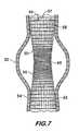
- FIG. 7is a graft comprising a woven tube according to the invention.
- FIG. 8is a graft comprising a bifurcated woven tube according to the invention.
- FIG. 7shows an endoluminal stent graft 50 used to treat a fusiform aneurysm 52 in an artery 54 .
- Stent graft 50comprises a tube 56 woven from a plurality of warp yarns 57 and fill yarns 59 and having three regions, 58 , 60 and 62 , of differing flexibility. Regions 58 and 62 form the upstream and downstream ends, respectively, of the tube 56 , where the tube attaches circumferentially around the artery 54 and must form a seal which will prevent leaks into the aneurysm 52 .
- arteriesare not usually round, may have calcified occlusions, are different in size from one another and may tend to expand in diameter with age.
- Radial flexibility of the regions 58 and 62is controlled by using elastic fill yarns 59 in the fill direction circumferentially around the tube and varying the tension and density at which these fill yarns are woven.
- the fill yarnsare woven under relatively less tension and/or at relatively lower density (picks per length of tube) than other regions of the tube. Because they are woven under less tension, the elastic yarns are locked into the fabric substantially unstretched and are subsequently able to stretch elastically in the fill direction when required to allow radial expansion of the tube to match the diameter and shape of the artery.
- the lower density of the fill yarnsalso increases the radial flexibility as there are generally fewer yarns per unit area which must be stretched, allowing the regions 58 and 62 to be expanded by relatively lower loads than if a higher density of yarns were used.
- a side benefit of the lower weave density at the end regions 58 and 62is that it may provide interstices of a size which encourage the ingrowth of endothelial cells which line the artery, thereby effecting a natural seal between graft and vessel.
- the tube 56It is not desirable that the tube 56 have significant radial flexibility in the region 60 adjacent to aneurysm 52 . This region must maintain its diameter under the hydraulic pressure of the blood as it is pumped through the artery so that it relieves the pressure on the aneurysm 52 . Significant radial flexibility in this region would defeat the purpose of the graft as it would allow the tube 56 to expand and place pressure on the artery at the aneurysm.
- the radially stiff region 60is formed by weaving the elastic fill yarns comprising the tube under relatively higher tension than the fill yarns in regions 58 and 62 .
- the tensionis above the elastic limit but below the ultimate tensile strength of the fill yarns in region 60 .
- the yarns, stretched by the tension force during weaving and locked in the fabric in the stretched state,are not capable of further significant stretching elastically when radial forces are applied to the interior of the tube, as occurs, for example, due to the hydraulic pressure during heartbeats.
- the density of the fill yarnsmay also be increased to provide further radial stiffness to the tube in region 60 . With more yarns per unit length, it requires greater force to radially expand the tube, yielding relatively greater stiffness in the fill direction for the region 60 . Greater yarn density also has the added benefit of reducing the porosity and preventing leakage of blood from the stent graft at the aneurysm.
- the tension of the fill yarns 59is controlled by the loom's shuttle trigger tension, which can be set to a relatively low value when region 58 is being woven, resulting in substantially unstretched fill yarns and a tube having relatively greater radial flexibility and compliance over region 58 .
- the shuttle trigger tensionmay be increased as region 60 is being woven to insert substantially stretched yarns in the fill direction, yielding a relatively stiff tube radially over region 60 .
- region 62is woven, the shuttle trigger tension is again reduced, inserting substantially unstretched fill yarns under low tension and producing a region of the tube having relatively greater radial flexibility and compliance.
- the density of the fill yarnsmay be controlled by a pick wheel as is well understood in the art.
- the elastic yarns used to weave tube 56are preferably highly textured yarns of polyester. Polytetrafluoroethylene, polypropylene or other biocompatible materials are also feasible. The textured nature of the yarns provides the required elastic properties. Alternatively, the elastic property of the yarns may be obtained by using inherently elastic materials, such as silicone, polyurethane or rubber to form the yarns. Crimped yarns may also be employed to provide fill yarns wherein the tension may be varied to change the radial stiffness of the tube.
- a practical example of a stent graft 50may comprise a tube 12 inches in length, 1.2 inches in diameter, having fill yarns of textured polyester of 40 denier initially woven at a shuttle trigger tension of 100 grams and a fill density of 60 picks per inch to form region 58 .
- the shuttle trigger tensionis then increased to 140 grams and the fill density of the fill yarns is increased to 68 picks per inch to weave region 60 , being relatively stiffer in the fill direction.
- Region 62is then woven at the same parameters as region 58 , although the parameters need not be the same.
- FIG. 8shows a stent graft 66 used to treat a fusiform aneurysm 68 in an aortic artery 70 near the iliac arteries 72 and 74 .
- Stent graft 66comprises a bifurcated tube 76 having a main tube 78 and two branch tubes 80 and 82 . Both the main and branch tubes are woven from a plurality of warp yarns 57 and fill yarns 59 , the warp yarns being oriented in a warp direction oriented lengthwise along the main and branch tubes, the fill yarns being oriented in a fill direction circumferentially around the tubes.
- Bifurcated tube 76provides an example of a stent graft which will benefit from controlling the flexibility of the tube in both the fill and warp directions.
- the tube 56it is advantageous to provide relatively greater flexibility oriented in the fill direction (circumferentially) in regions of tube 76 such as 88 , 90 and 92 which are areas where the tube requires greater radial compliance and flexibility to effect a seal to the artery.
- relatively low radial flexibilityis desired for the region 94 adjacent to the aneurysm.
- the radial flexibility characteristics for the bifurcated tube 76are controlled in the same way as described above for the conventional tube 56 , i.e., by controlling the tension under which the fill yarns are woven when forming the various regions of the tube.
- the relative flexibility of the branch tubes 80 and 82 in the warp direction over regions 96 and 98is controlled by using elastic warp yarns in the warp direction and weaving the warp yarns under relatively greater or lesser tension. If relatively greater flexibility in the warp direction is desired, the warp yarns are woven under relatively less tension than other regions of the tube 76 . The warp yarns woven under the lower tension are substantially unstretched when they are woven into the fabric and will, therefore, be able to stretch elastically under load, allowing the tube to stretch lengthwise and accommodate the curvature of the artery. Conversely, if relatively less flexibility is desired in the warp direction, the warp yarns are stretched under relatively greater tension (preferably in excess of the elastic limit) as they are woven into the fabric. The stretched yarns are locked into the fabric by the fill yarns and provide relatively little lengthwise flexibility since they are already stretched above their elastic limit and have little or no elasticity left.
- the warp yarnsare preferably highly textured yarns comprised of polyester, polytetrafluoroethylene, polypropylene or other biocompatible materials.
- Further control of the longitudinal flexibilitymay be provided by weaving the tube 76 with the warp yarns closer or farther apart, thereby controlling the warp yarn density (the number of yarns per unit length). Denser weaves are necessarily woven under relatively higher yarn tension which tends to pre-stretch the yarn, leaving little capacity for the yarn to stretch further once woven into the tube. This results in a tube with relatively less flexibility in the warp direction but achieves relatively low fabric porosity due to the relatively higher yarn density. In contrast, less dense weaves are woven under relatively less tension, and the warp yarns are not pre-stretched to the same degree and, when interwoven to form the tube, consequently allow it to stretch with relatively greater longitudinal flexibility. Such tubes have relatively higher porosity, however, and are, therefore, more permeable. Control of the warp yarn density may be effected by varying the separation of the tines of the comb through which the warp yarns pass on the loom.
- a practical example of a bifurcated tube 76 useable as a stent graftmay comprise a main tube 5 inches in length, 1.2 inches in diameter and branch tubes 6 inches in length and 0.7 inches in diameter, the tubes being formed of textured polyester yarns of 40 denier. Fill yarns 59 in regions 88 , 90 and 92 near the ends of the tubes are woven at a shuttle trigger tension of 100 grams and a fill density of 60 picks per inch to provide relatively greater flexibility in the fill direction, allowing the tube to expand radially and accommodate and seal to the vessel 70 .
- the fill yarns in region 94located adjacent to the aneurysm 68 , are woven at an increased shuttle trigger tension of 140 grams, and the fill density may be increased to 68 picks per inch to provide relatively less flexibility in the fill direction over region 94 .
- Regions 88 and 94are woven with warp yarns under a relatively high tension of 10 grams to provide relatively lower warp direction flexibility over these regions.
- the warp yarn tension and densityis changed when branch tubes 80 and 82 are being woven.
- the warp yarn tensionis reduced to 7 grams and the warp yarn density is reduced from 140 to 130 ends per inch.
- Fabric tubes with regions of varying flexibility in the warp and fill directionswill provide improved stent grafts for the repair of vascular aneurysms.
- Relatively greater flexibility in the fill directionwill provide for a better seal between the graft and the artery, lessening the likelihood of leakage or obstruction of the artery and allow one size of graft to accommodate a wide range of different size and shape arteries.
- Relatively greater flexibility in the warp directionwill allow the graft to conform to the curvature of the artery as it twists and bends without folding or causing kinking of the vessel.
- the overall increased flexibilityis attained without significantly increasing the bulk of the graft thus allowing the graft to be more easily moved through a catheter for delivery to the site of the aneurysm.
Landscapes
- Health & Medical Sciences (AREA)
- Engineering & Computer Science (AREA)
- Biomedical Technology (AREA)
- Life Sciences & Earth Sciences (AREA)
- Pulmonology (AREA)
- Cardiology (AREA)
- Oral & Maxillofacial Surgery (AREA)
- Transplantation (AREA)
- Textile Engineering (AREA)
- Heart & Thoracic Surgery (AREA)
- Vascular Medicine (AREA)
- Gastroenterology & Hepatology (AREA)
- Animal Behavior & Ethology (AREA)
- General Health & Medical Sciences (AREA)
- Public Health (AREA)
- Veterinary Medicine (AREA)
- Prostheses (AREA)
- Woven Fabrics (AREA)
- Looms (AREA)
Abstract
Description
Claims (21)
Priority Applications (1)
| Application Number | Priority Date | Filing Date | Title |
|---|---|---|---|
| US10/003,901US6814754B2 (en) | 2000-10-30 | 2001-10-25 | Woven tubular graft with regions of varying flexibility |
Applications Claiming Priority (2)
| Application Number | Priority Date | Filing Date | Title |
|---|---|---|---|
| US24424000P | 2000-10-30 | 2000-10-30 | |
| US10/003,901US6814754B2 (en) | 2000-10-30 | 2001-10-25 | Woven tubular graft with regions of varying flexibility |
Publications (2)
| Publication Number | Publication Date |
|---|---|
| US20020058992A1 US20020058992A1 (en) | 2002-05-16 |
| US6814754B2true US6814754B2 (en) | 2004-11-09 |
Family
ID=22921951
Family Applications (1)
| Application Number | Title | Priority Date | Filing Date |
|---|---|---|---|
| US10/003,901Expired - LifetimeUS6814754B2 (en) | 2000-10-30 | 2001-10-25 | Woven tubular graft with regions of varying flexibility |
Country Status (4)
| Country | Link |
|---|---|
| US (1) | US6814754B2 (en) |
| EP (1) | EP1341480A2 (en) |
| AU (1) | AU2002230774A1 (en) |
| WO (1) | WO2002035989A2 (en) |
Cited By (82)
| Publication number | Priority date | Publication date | Assignee | Title |
|---|---|---|---|---|
| US20050027346A1 (en)* | 2003-02-06 | 2005-02-03 | Mike Arkusz | Pulsating Stent Graft |
| US20060069401A1 (en)* | 2004-09-27 | 2006-03-30 | Wright David W | Fastener apparatus for tissue and methods of deployment and manufacture |
| US20080228028A1 (en)* | 2007-03-12 | 2008-09-18 | Cook Incorporated | Woven fabric with shape memory element strands |
| US7465318B2 (en) | 2004-04-15 | 2008-12-16 | Soteira, Inc. | Cement-directing orthopedic implants |
| US20090157164A1 (en)* | 2007-08-24 | 2009-06-18 | Cook Incorporated | Textile graft for in situ fenestration |
| US20090171451A1 (en)* | 2007-12-27 | 2009-07-02 | Cook Incorporated | Implantable device having composite weave |
| US20090171443A1 (en)* | 2007-12-27 | 2009-07-02 | Cook Incorporated | Stent graft having floating yarns |
| US20090171435A1 (en)* | 2007-12-27 | 2009-07-02 | Cook Incorporated | Implantable graft device having treated yarn and method for making same |
| US20090171450A1 (en)* | 2007-12-17 | 2009-07-02 | Aesculap Ag, A Corporation Of Germany | Woven Textile Vascular Prosthesis |
| US20100137969A1 (en)* | 2004-04-23 | 2010-06-03 | Boston Scientific Scimed, Inc. | Composite Medical Textile Material and Implantable Devices Made Therefrom |
| US20100151114A1 (en)* | 2008-12-17 | 2010-06-17 | Zimmer, Inc. | In-line treatment of yarn prior to creating a fabric |
| US20100161025A1 (en)* | 2008-08-29 | 2010-06-24 | Cook, Incorporated | Variable weave graft with metal strand reinforcement for in situ fenestration |
| USD626233S1 (en) | 2008-02-28 | 2010-10-26 | Stryker Spine | Expandable intervertebral implant |
| US7909873B2 (en) | 2006-12-15 | 2011-03-22 | Soteira, Inc. | Delivery apparatus and methods for vertebrostenting |
| EP2710966A1 (en)* | 2012-09-20 | 2014-03-26 | DePuy Mitek, LLC | Methods and devices for threading sutures |
| US8833402B2 (en)* | 2010-12-30 | 2014-09-16 | Cook Medical Technologies Llc | Woven fabric having composite yarns for endoluminal devices |
| US9173733B1 (en)* | 2006-08-21 | 2015-11-03 | Abbott Cardiovascular Systems Inc. | Tracheobronchial implantable medical device and methods of use |
| US9192397B2 (en) | 2006-12-15 | 2015-11-24 | Gmedelaware 2 Llc | Devices and methods for fracture reduction |
| US9320610B2 (en) | 2011-08-16 | 2016-04-26 | Stryker European Holdings I, Llc | Expandable implant |
| US9358140B1 (en) | 2009-11-18 | 2016-06-07 | Aneuclose Llc | Stent with outer member to embolize an aneurysm |
| US9393110B2 (en) | 2010-10-05 | 2016-07-19 | Edwards Lifesciences Corporation | Prosthetic heart valve |
| US20160220396A1 (en)* | 2011-09-09 | 2016-08-04 | Isis Innovation Limited | Stent and method of inserting a stent into a delivery catheter |
| US9480485B2 (en) | 2006-12-15 | 2016-11-01 | Globus Medical, Inc. | Devices and methods for vertebrostenting |
| US9636221B2 (en) | 2007-09-26 | 2017-05-02 | St. Jude Medical, Inc. | Collapsible prosthetic heart valves |
| US9675449B2 (en) | 2008-07-15 | 2017-06-13 | St. Jude Medical, Llc | Collapsible and re-expandable prosthetic heart valve cuff designs and complementary technological applications |
| US9820851B2 (en) | 2007-09-28 | 2017-11-21 | St. Jude Medical, Llc | Collapsible-expandable prosthetic heart valves with structures for clamping native tissue |
| US9827086B2 (en)* | 2012-11-13 | 2017-11-28 | The Secant Group, Llc | Tapered tubular implant formed from woven fabric |
| US9913715B2 (en) | 2013-11-06 | 2018-03-13 | St. Jude Medical, Cardiology Division, Inc. | Paravalvular leak sealing mechanism |
| US9938646B2 (en)* | 2015-03-08 | 2018-04-10 | Apple Inc. | Woven band with different stretch regions |
| US9974650B2 (en) | 2015-07-14 | 2018-05-22 | Edwards Lifesciences Corporation | Prosthetic heart valve |
| US10028747B2 (en) | 2008-05-01 | 2018-07-24 | Aneuclose Llc | Coils with a series of proximally-and-distally-connected loops for occluding a cerebral aneurysm |
| US10154904B2 (en) | 2014-04-28 | 2018-12-18 | Edwards Lifesciences Corporation | Intravascular introducer devices |
| US10179043B2 (en) | 2016-02-12 | 2019-01-15 | Edwards Lifesciences Corporation | Prosthetic heart valve having multi-level sealing member |
| US10195025B2 (en) | 2014-05-12 | 2019-02-05 | Edwards Lifesciences Corporation | Prosthetic heart valve |
| US10201417B2 (en) | 2015-02-03 | 2019-02-12 | Boston Scientific Scimed Inc. | Prosthetic heart valve having tubular seal |
| US10201416B2 (en) | 2016-05-16 | 2019-02-12 | Boston Scientific Scimed, Inc. | Replacement heart valve implant with invertible leaflets |
| US10201418B2 (en) | 2010-09-10 | 2019-02-12 | Symetis, SA | Valve replacement devices, delivery device for a valve replacement device and method of production of a valve replacement device |
| US10206774B2 (en) | 2003-12-23 | 2019-02-19 | Boston Scientific Scimed Inc. | Low profile heart valve and delivery system |
| US10232564B2 (en) | 2015-04-29 | 2019-03-19 | Edwards Lifesciences Corporation | Laminated sealing member for prosthetic heart valve |
| US10258465B2 (en) | 2003-12-23 | 2019-04-16 | Boston Scientific Scimed Inc. | Methods and apparatus for endovascular heart valve replacement comprising tissue grasping elements |
| US10266972B2 (en) | 2010-10-21 | 2019-04-23 | Albany Engineered Composites, Inc. | Woven preforms, fiber reinforced composites, and methods of making thereof |
| US10278805B2 (en) | 2000-08-18 | 2019-05-07 | Atritech, Inc. | Expandable implant devices for filtering blood flow from atrial appendages |
| US10299922B2 (en) | 2005-12-22 | 2019-05-28 | Symetis Sa | Stent-valves for valve replacement and associated methods and systems for surgery |
| US10314695B2 (en) | 2003-12-23 | 2019-06-11 | Boston Scientific Scimed Inc. | Methods and apparatus for endovascular heart valve replacement comprising tissue grasping elements |
| US10335273B2 (en) | 2003-12-23 | 2019-07-02 | Boston Scientific Scimed Inc. | Leaflet engagement elements and methods for use thereof |
| US10342675B2 (en) | 2013-03-11 | 2019-07-09 | Stryker European Holdings I, Llc | Expandable implant |
| US10413409B2 (en) | 2003-12-23 | 2019-09-17 | Boston Scientific Scimed, Inc. | Systems and methods for delivering a medical implant |
| US10426608B2 (en) | 2003-12-23 | 2019-10-01 | Boston Scientific Scimed, Inc. | Repositionable heart valve |
| US10426617B2 (en) | 2015-03-06 | 2019-10-01 | Boston Scientific Scimed, Inc. | Low profile valve locking mechanism and commissure assembly |
| US10531952B2 (en) | 2004-11-05 | 2020-01-14 | Boston Scientific Scimed, Inc. | Medical devices and delivery systems for delivering medical devices |
| US10548734B2 (en) | 2005-09-21 | 2020-02-04 | Boston Scientific Scimed, Inc. | Venous valve, system, and method with sinus pocket |
| US10555809B2 (en) | 2012-06-19 | 2020-02-11 | Boston Scientific Scimed, Inc. | Replacement heart valve |
| US10631977B2 (en) | 2015-08-24 | 2020-04-28 | Edwards Lifesciences Corporation | Covering and assembly method for transcatheter valve |
| US10716573B2 (en) | 2008-05-01 | 2020-07-21 | Aneuclose | Janjua aneurysm net with a resilient neck-bridging portion for occluding a cerebral aneurysm |
| US10828154B2 (en) | 2017-06-08 | 2020-11-10 | Boston Scientific Scimed, Inc. | Heart valve implant commissure support structure |
| US10898325B2 (en) | 2017-08-01 | 2021-01-26 | Boston Scientific Scimed, Inc. | Medical implant locking mechanism |
| US10939996B2 (en) | 2017-08-16 | 2021-03-09 | Boston Scientific Scimed, Inc. | Replacement heart valve commissure assembly |
| US10993805B2 (en) | 2008-02-26 | 2021-05-04 | Jenavalve Technology, Inc. | Stent for the positioning and anchoring of a valvular prosthesis in an implantation site in the heart of a patient |
| US11065138B2 (en) | 2016-05-13 | 2021-07-20 | Jenavalve Technology, Inc. | Heart valve prosthesis delivery system and method for delivery of heart valve prosthesis with introducer sheath and loading system |
| US11147668B2 (en) | 2018-02-07 | 2021-10-19 | Boston Scientific Scimed, Inc. | Medical device delivery system with alignment feature |
| US11185405B2 (en) | 2013-08-30 | 2021-11-30 | Jenavalve Technology, Inc. | Radially collapsible frame for a prosthetic valve and method for manufacturing such a frame |
| US11191641B2 (en) | 2018-01-19 | 2021-12-07 | Boston Scientific Scimed, Inc. | Inductance mode deployment sensors for transcatheter valve system |
| US11197754B2 (en) | 2017-01-27 | 2021-12-14 | Jenavalve Technology, Inc. | Heart valve mimicry |
| US11229517B2 (en) | 2018-05-15 | 2022-01-25 | Boston Scientific Scimed, Inc. | Replacement heart valve commissure assembly |
| US11241310B2 (en) | 2018-06-13 | 2022-02-08 | Boston Scientific Scimed, Inc. | Replacement heart valve delivery device |
| US11241312B2 (en) | 2018-12-10 | 2022-02-08 | Boston Scientific Scimed, Inc. | Medical device delivery system including a resistance member |
| US11246625B2 (en) | 2018-01-19 | 2022-02-15 | Boston Scientific Scimed, Inc. | Medical device delivery system with feedback loop |
| US11278398B2 (en) | 2003-12-23 | 2022-03-22 | Boston Scientific Scimed, Inc. | Methods and apparatus for endovascular heart valve replacement comprising tissue grasping elements |
| US11337800B2 (en) | 2015-05-01 | 2022-05-24 | Jenavalve Technology, Inc. | Device and method with reduced pacemaker rate in heart valve replacement |
| US11357624B2 (en) | 2007-04-13 | 2022-06-14 | Jenavalve Technology, Inc. | Medical device for treating a heart valve insufficiency |
| US11439504B2 (en) | 2019-05-10 | 2022-09-13 | Boston Scientific Scimed, Inc. | Replacement heart valve with improved cusp washout and reduced loading |
| US11439732B2 (en) | 2018-02-26 | 2022-09-13 | Boston Scientific Scimed, Inc. | Embedded radiopaque marker in adaptive seal |
| US11517431B2 (en) | 2005-01-20 | 2022-12-06 | Jenavalve Technology, Inc. | Catheter system for implantation of prosthetic heart valves |
| US11564794B2 (en) | 2008-02-26 | 2023-01-31 | Jenavalve Technology, Inc. | Stent for the positioning and anchoring of a valvular prosthesis in an implantation site in the heart of a patient |
| US11589981B2 (en) | 2010-05-25 | 2023-02-28 | Jenavalve Technology, Inc. | Prosthetic heart valve and transcatheter delivered endoprosthesis comprising a prosthetic heart valve and a stent |
| US20230104472A1 (en)* | 2021-10-04 | 2023-04-06 | The Secant Group, Llc | Integrally woven manifolds and methods for forming |
| US11759317B2 (en) | 2016-12-20 | 2023-09-19 | Edwards Lifesciences Corporation | Three-dimensional woven fabric implant devices |
| US11771544B2 (en) | 2011-05-05 | 2023-10-03 | Symetis Sa | Method and apparatus for compressing/loading stent-valves |
| US11969335B2 (en) | 2020-04-28 | 2024-04-30 | Cook Medical Technologies Llc | Woven graft having a taper with a re-engaged warp end |
| US12121461B2 (en) | 2015-03-20 | 2024-10-22 | Jenavalve Technology, Inc. | Heart valve prosthesis delivery system and method for delivery of heart valve prosthesis with introducer sheath |
| US12171658B2 (en) | 2022-11-09 | 2024-12-24 | Jenavalve Technology, Inc. | Catheter system for sequential deployment of an expandable implant |
| US12414854B2 (en) | 2010-05-20 | 2025-09-16 | Jenavalve Technology, Inc. | Catheter system for introducing an expandable stent into the body of a patient |
Families Citing this family (25)
| Publication number | Priority date | Publication date | Assignee | Title |
|---|---|---|---|---|
| US6287335B1 (en)* | 1999-04-26 | 2001-09-11 | William J. Drasler | Intravascular folded tubular endoprosthesis |
| US20030055494A1 (en)* | 2001-07-27 | 2003-03-20 | Deon Bezuidenhout | Adventitial fabric reinforced porous prosthetic graft |
| US7147661B2 (en) | 2001-12-20 | 2006-12-12 | Boston Scientific Santa Rosa Corp. | Radially expandable stent |
| ITMO20020349A1 (en)* | 2002-12-06 | 2004-06-07 | G A M A H S Srl | PROSTHESIS FOR LARGE BLOOD VESSELS. |
| US20050131520A1 (en) | 2003-04-28 | 2005-06-16 | Zilla Peter P. | Compliant blood vessel graft |
| US7998188B2 (en) | 2003-04-28 | 2011-08-16 | Kips Bay Medical, Inc. | Compliant blood vessel graft |
| JP4692902B2 (en)* | 2003-04-28 | 2011-06-01 | キップス・ベイ・メディカル・インコーポレーテッド | Flexible vein graft |
| DE102007063267A1 (en)* | 2007-12-17 | 2009-06-18 | Aesculap Ag | Woven textile vascular prosthesis for forming branch of end-to-side anastomosis, has tubular section comprising hopper, and prosthesis wall in region of concave curve, where wall is weaved thicker than in region with original web connection |
| DE102007063266A1 (en)* | 2007-12-17 | 2009-06-18 | Aesculap Ag | Seemed textile vascular prosthesis for forming branch of end-to-side anastomosis, has tubular section, which has asymmetrically extended funnel with opening for forming aerodynamic junction at end |
| EP2331011B1 (en)* | 2008-08-29 | 2015-01-14 | Cook Medical Technologies LLC | Prosthesis with moveable fenestration |
| EP2361326A2 (en)* | 2008-10-15 | 2011-08-31 | Stretchline Intellectual Properties Limited | Elastic fabrics and methods and apparatus for making the same |
| EP2519190B1 (en) | 2009-12-28 | 2016-02-10 | Cook Medical Technologies LLC | Thoracic graft having yarn modifications |
| JP5856170B2 (en)* | 2010-08-16 | 2016-02-09 | フェデラル−モーグル パワートレイン インコーポレイテッドFederal−Mogul Powertrain, Inc. | Self-winding woven sleeve without twist and method of construction thereof |
| CA2748206C (en) | 2010-08-21 | 2015-06-23 | Blayne A. Roeder | Prosthesis having pivoting fenestration |
| US8702786B2 (en) | 2010-08-21 | 2014-04-22 | Cook Medical Technologies Llc | Prosthesis having pivoting fenestration |
| US8870939B2 (en) | 2010-08-21 | 2014-10-28 | Cook Medical Technologies Llc | Prosthesis having pivoting fenestration |
| US8771336B2 (en) | 2010-08-21 | 2014-07-08 | Cook Medical Technologies Llc | Endoluminal prosthesis comprising a valve replacement and at least one fenestration |
| US8728148B2 (en) | 2011-11-09 | 2014-05-20 | Cook Medical Technologies Llc | Diameter reducing tie arrangement for endoluminal prosthesis |
| WO2013119332A2 (en) | 2012-02-09 | 2013-08-15 | Stout Medical Group, L.P. | Embolic device and methods of use |
| US10265202B2 (en) | 2013-03-14 | 2019-04-23 | Cook Medical Technologies Llc | Prosthesis having an everting pivoting fenestration |
| JP6241969B2 (en) | 2014-05-28 | 2017-12-06 | ストライカー ヨーロピアン ホールディングス I,エルエルシーStryker European Holdings I,Llc | Vascular occlusion device and method of use thereof |
| US9060777B1 (en)* | 2014-05-28 | 2015-06-23 | Tw Medical Technologies, Llc | Vaso-occlusive devices and methods of use |
| US10159490B2 (en) | 2015-05-08 | 2018-12-25 | Stryker European Holdings I, Llc | Vaso-occlusive devices |
| AR104494A1 (en) | 2016-04-27 | 2017-07-26 | Daniel Barone Hector | AORTIC PROSTHETICS FOR THE TREATMENT OF ABDOMINAL AORTIC ANEURISMS |
| GB201806097D0 (en) | 2018-04-13 | 2018-05-30 | Heart Biotech Nano Ltd | Vascular graft |
Citations (6)
| Publication number | Priority date | Publication date | Assignee | Title |
|---|---|---|---|---|
| US967585A (en) | 1908-02-12 | 1910-08-16 | Wilhelm Julius Teufel | Compressive hose. |
| US2117974A (en) | 1935-07-13 | 1938-05-17 | Moore Fab Co | Tubular woven elastic garment |
| US3304557A (en) | 1965-09-28 | 1967-02-21 | Ethicon Inc | Surgical prosthesis |
| US5653746A (en)* | 1994-03-08 | 1997-08-05 | Meadox Medicals, Inc. | Radially expandable tubular prosthesis |
| US5800514A (en) | 1996-05-24 | 1998-09-01 | Meadox Medicals, Inc. | Shaped woven tubular soft-tissue prostheses and methods of manufacturing |
| WO1999040875A1 (en)* | 1998-02-12 | 1999-08-19 | Prodesco, Inc. | Tapered tubular prosthesis and method of making |
- 2001
- 2001-10-25USUS10/003,901patent/US6814754B2/ennot_activeExpired - Lifetime
- 2001-10-30AUAU2002230774Apatent/AU2002230774A1/ennot_activeAbandoned
- 2001-10-30EPEP01991020Apatent/EP1341480A2/ennot_activeWithdrawn
- 2001-10-30WOPCT/US2001/047941patent/WO2002035989A2/ennot_activeApplication Discontinuation
Patent Citations (6)
| Publication number | Priority date | Publication date | Assignee | Title |
|---|---|---|---|---|
| US967585A (en) | 1908-02-12 | 1910-08-16 | Wilhelm Julius Teufel | Compressive hose. |
| US2117974A (en) | 1935-07-13 | 1938-05-17 | Moore Fab Co | Tubular woven elastic garment |
| US3304557A (en) | 1965-09-28 | 1967-02-21 | Ethicon Inc | Surgical prosthesis |
| US5653746A (en)* | 1994-03-08 | 1997-08-05 | Meadox Medicals, Inc. | Radially expandable tubular prosthesis |
| US5800514A (en) | 1996-05-24 | 1998-09-01 | Meadox Medicals, Inc. | Shaped woven tubular soft-tissue prostheses and methods of manufacturing |
| WO1999040875A1 (en)* | 1998-02-12 | 1999-08-19 | Prodesco, Inc. | Tapered tubular prosthesis and method of making |
Cited By (164)
| Publication number | Priority date | Publication date | Assignee | Title |
|---|---|---|---|---|
| US10278805B2 (en) | 2000-08-18 | 2019-05-07 | Atritech, Inc. | Expandable implant devices for filtering blood flow from atrial appendages |
| US20050027346A1 (en)* | 2003-02-06 | 2005-02-03 | Mike Arkusz | Pulsating Stent Graft |
| US9271825B2 (en)* | 2003-02-06 | 2016-03-01 | Mike Arkusz | Pulsating stent graft |
| US10335273B2 (en) | 2003-12-23 | 2019-07-02 | Boston Scientific Scimed Inc. | Leaflet engagement elements and methods for use thereof |
| US11185408B2 (en) | 2003-12-23 | 2021-11-30 | Boston Scientific Scimed, Inc. | Methods and apparatus for endovascular heart valve replacement comprising tissue grasping elements |
| US10206774B2 (en) | 2003-12-23 | 2019-02-19 | Boston Scientific Scimed Inc. | Low profile heart valve and delivery system |
| US10426608B2 (en) | 2003-12-23 | 2019-10-01 | Boston Scientific Scimed, Inc. | Repositionable heart valve |
| US10413409B2 (en) | 2003-12-23 | 2019-09-17 | Boston Scientific Scimed, Inc. | Systems and methods for delivering a medical implant |
| US11278398B2 (en) | 2003-12-23 | 2022-03-22 | Boston Scientific Scimed, Inc. | Methods and apparatus for endovascular heart valve replacement comprising tissue grasping elements |
| US10258465B2 (en) | 2003-12-23 | 2019-04-16 | Boston Scientific Scimed Inc. | Methods and apparatus for endovascular heart valve replacement comprising tissue grasping elements |
| US10314695B2 (en) | 2003-12-23 | 2019-06-11 | Boston Scientific Scimed Inc. | Methods and apparatus for endovascular heart valve replacement comprising tissue grasping elements |
| US7465318B2 (en) | 2004-04-15 | 2008-12-16 | Soteira, Inc. | Cement-directing orthopedic implants |
| US8100973B2 (en) | 2004-04-15 | 2012-01-24 | Soteira, Inc. | Cement-directing orthopedic implants |
| US8343207B2 (en)* | 2004-04-23 | 2013-01-01 | Ronald Rakos | Composite medical textile material and implantable devices made therefrom |
| US20100137969A1 (en)* | 2004-04-23 | 2010-06-03 | Boston Scientific Scimed, Inc. | Composite Medical Textile Material and Implantable Devices Made Therefrom |
| US9486216B2 (en)* | 2004-09-27 | 2016-11-08 | David W. Wright | Fastener apparatus for tissue and methods of deployment and manufacture |
| US20060069401A1 (en)* | 2004-09-27 | 2006-03-30 | Wright David W | Fastener apparatus for tissue and methods of deployment and manufacture |
| US10531952B2 (en) | 2004-11-05 | 2020-01-14 | Boston Scientific Scimed, Inc. | Medical devices and delivery systems for delivering medical devices |
| US11517431B2 (en) | 2005-01-20 | 2022-12-06 | Jenavalve Technology, Inc. | Catheter system for implantation of prosthetic heart valves |
| US10548734B2 (en) | 2005-09-21 | 2020-02-04 | Boston Scientific Scimed, Inc. | Venous valve, system, and method with sinus pocket |
| US10314701B2 (en) | 2005-12-22 | 2019-06-11 | Symetis Sa | Stent-valves for valve replacement and associated methods and systems for surgery |
| US10299922B2 (en) | 2005-12-22 | 2019-05-28 | Symetis Sa | Stent-valves for valve replacement and associated methods and systems for surgery |
| US9833342B2 (en)* | 2006-08-21 | 2017-12-05 | Abbott Cardiovascular Systems Inc. | Tracheobronchial implantable medical device and methods of use |
| US9173733B1 (en)* | 2006-08-21 | 2015-11-03 | Abbott Cardiovascular Systems Inc. | Tracheobronchial implantable medical device and methods of use |
| US20160022449A1 (en)* | 2006-08-21 | 2016-01-28 | Abbott Cardiovascular Systems, Inc. | Tracheobronchial implantable medical device and methods of use |
| US8623025B2 (en) | 2006-12-15 | 2014-01-07 | Gmedelaware 2 Llc | Delivery apparatus and methods for vertebrostenting |
| US9480485B2 (en) | 2006-12-15 | 2016-11-01 | Globus Medical, Inc. | Devices and methods for vertebrostenting |
| US9192397B2 (en) | 2006-12-15 | 2015-11-24 | Gmedelaware 2 Llc | Devices and methods for fracture reduction |
| US9237916B2 (en) | 2006-12-15 | 2016-01-19 | Gmedeleware 2 Llc | Devices and methods for vertebrostenting |
| US7909873B2 (en) | 2006-12-15 | 2011-03-22 | Soteira, Inc. | Delivery apparatus and methods for vertebrostenting |
| US20080228028A1 (en)* | 2007-03-12 | 2008-09-18 | Cook Incorporated | Woven fabric with shape memory element strands |
| US8940041B2 (en) | 2007-03-12 | 2015-01-27 | Cook Medical Technologies Llc | Woven fabric with shape memory element strands |
| US9427342B2 (en) | 2007-03-12 | 2016-08-30 | Cook Medical Technologies Llc | Woven fabric with shape memory element strands |
| US8177834B2 (en) | 2007-03-12 | 2012-05-15 | Cook Medical Technologies Llc | Woven fabric with shape memory element strands |
| US11357624B2 (en) | 2007-04-13 | 2022-06-14 | Jenavalve Technology, Inc. | Medical device for treating a heart valve insufficiency |
| US8597342B2 (en) | 2007-08-24 | 2013-12-03 | Cook Medical Technologies Llc | Textile graft for in situ fenestration |
| US20090157164A1 (en)* | 2007-08-24 | 2009-06-18 | Cook Incorporated | Textile graft for in situ fenestration |
| US11007053B2 (en) | 2007-09-26 | 2021-05-18 | St. Jude Medical, Llc | Collapsible prosthetic heart valves |
| US11903823B2 (en) | 2007-09-26 | 2024-02-20 | St. Jude Medical, Llc | Collapsible prosthetic heart valves |
| US9693859B2 (en) | 2007-09-26 | 2017-07-04 | St. Jude Medical, Llc | Collapsible prosthetic heart valves |
| US10292813B2 (en) | 2007-09-26 | 2019-05-21 | St. Jude Medical, Llc | Collapsible prosthetic heart valves |
| US9636221B2 (en) | 2007-09-26 | 2017-05-02 | St. Jude Medical, Inc. | Collapsible prosthetic heart valves |
| US11660187B2 (en) | 2007-09-28 | 2023-05-30 | St. Jude Medical, Llc | Collapsible-expandable prosthetic heart valves with structures for clamping native tissue |
| US11382740B2 (en) | 2007-09-28 | 2022-07-12 | St. Jude Medical, Llc | Collapsible-expandable prosthetic heart valves with structures for clamping native tissue |
| US11534294B2 (en) | 2007-09-28 | 2022-12-27 | St. Jude Medical, Llc | Collapsible-expandable prosthetic heart valves with structures for clamping native tissue |
| US9820851B2 (en) | 2007-09-28 | 2017-11-21 | St. Jude Medical, Llc | Collapsible-expandable prosthetic heart valves with structures for clamping native tissue |
| US12138161B2 (en) | 2007-09-28 | 2024-11-12 | St. Jude Medical, Llc | Collapsible-expandable prosthetic heart valves with structures for clamping native tissue |
| US10426604B2 (en) | 2007-09-28 | 2019-10-01 | St. Jude Medical, Llc | Collapsible-expandable prosthetic heart valves with structures for clamping native tissue |
| US8728151B2 (en)* | 2007-12-17 | 2014-05-20 | Aesculap Ag | Woven textile vascular prosthesis |
| US20090171450A1 (en)* | 2007-12-17 | 2009-07-02 | Aesculap Ag, A Corporation Of Germany | Woven Textile Vascular Prosthesis |
| US8187316B2 (en) | 2007-12-27 | 2012-05-29 | Cook Medical Technologies Llc | Implantable graft device having treated yarn and method for making same |
| US20090171435A1 (en)* | 2007-12-27 | 2009-07-02 | Cook Incorporated | Implantable graft device having treated yarn and method for making same |
| US20090171443A1 (en)* | 2007-12-27 | 2009-07-02 | Cook Incorporated | Stent graft having floating yarns |
| US8881365B2 (en) | 2007-12-27 | 2014-11-11 | Cook Medical Technologies Llc | Implantable graft device having treated yarn and method for making same |
| US20090171451A1 (en)* | 2007-12-27 | 2009-07-02 | Cook Incorporated | Implantable device having composite weave |
| US8834552B2 (en) | 2007-12-27 | 2014-09-16 | Cook Medical Technologies Llc | Stent graft having floating yarns |
| US11154398B2 (en) | 2008-02-26 | 2021-10-26 | JenaValve Technology. Inc. | Stent for the positioning and anchoring of a valvular prosthesis in an implantation site in the heart of a patient |
| US10993805B2 (en) | 2008-02-26 | 2021-05-04 | Jenavalve Technology, Inc. | Stent for the positioning and anchoring of a valvular prosthesis in an implantation site in the heart of a patient |
| US11564794B2 (en) | 2008-02-26 | 2023-01-31 | Jenavalve Technology, Inc. | Stent for the positioning and anchoring of a valvular prosthesis in an implantation site in the heart of a patient |
| US12232957B2 (en) | 2008-02-26 | 2025-02-25 | Jenavalve Technology, Inc. | Stent for the positioning and anchoring of a valvular prosthesis in an implantation site in the heart of a patient |
| US9782271B2 (en) | 2008-02-28 | 2017-10-10 | Stryker European Holdings I, Llc | Expandable intervertebral implant |
| US8603170B2 (en) | 2008-02-28 | 2013-12-10 | Stryker Spine | Expandable intervertebral implant |
| USD626233S1 (en) | 2008-02-28 | 2010-10-26 | Stryker Spine | Expandable intervertebral implant |
| US8267939B2 (en) | 2008-02-28 | 2012-09-18 | Stryker Spine | Tool for implanting expandable intervertebral implant |
| US10028747B2 (en) | 2008-05-01 | 2018-07-24 | Aneuclose Llc | Coils with a series of proximally-and-distally-connected loops for occluding a cerebral aneurysm |
| US10716573B2 (en) | 2008-05-01 | 2020-07-21 | Aneuclose | Janjua aneurysm net with a resilient neck-bridging portion for occluding a cerebral aneurysm |
| US9687255B2 (en) | 2008-06-17 | 2017-06-27 | Globus Medical, Inc. | Device and methods for fracture reduction |
| US10588646B2 (en) | 2008-06-17 | 2020-03-17 | Globus Medical, Inc. | Devices and methods for fracture reduction |
| US11504228B2 (en) | 2008-07-15 | 2022-11-22 | St. Jude Medical, Llc | Collapsible and re-expandable prosthetic heart valve cuff designs and complementary technological applications |
| US10314694B2 (en) | 2008-07-15 | 2019-06-11 | St. Jude Medical, Llc | Collapsible and re-expandable prosthetic heart valve cuff designs and complementary technological applications |
| US9681949B2 (en) | 2008-07-15 | 2017-06-20 | St. Jude Medical, Llc | Collapsible and re-expandable prosthetic heart valve cuff designs and complementary technological applications |
| US9675449B2 (en) | 2008-07-15 | 2017-06-13 | St. Jude Medical, Llc | Collapsible and re-expandable prosthetic heart valve cuff designs and complementary technological applications |
| US10010410B2 (en) | 2008-07-15 | 2018-07-03 | St. Jude Medical, Llc | Collapsible and re-expandable prosthetic heart valve cuff designs and complementary technological applications |
| US12036112B2 (en) | 2008-07-15 | 2024-07-16 | St. Jude Medical, Llc | Collapsible and re-expandable prosthetic heart valve cuff designs and complementary technological applications |
| US12090047B2 (en) | 2008-07-15 | 2024-09-17 | St. Jude Medical, Llc | Collapsible and re-expandable prosthetic heart valve cuff designs and complementary technological applications |
| US8353943B2 (en) | 2008-08-29 | 2013-01-15 | Cook Medical Technologies Llc | Variable weave graft with metal strand reinforcement for in situ fenestration |
| US20100161025A1 (en)* | 2008-08-29 | 2010-06-24 | Cook, Incorporated | Variable weave graft with metal strand reinforcement for in situ fenestration |
| US20100151114A1 (en)* | 2008-12-17 | 2010-06-17 | Zimmer, Inc. | In-line treatment of yarn prior to creating a fabric |
| US9358140B1 (en) | 2009-11-18 | 2016-06-07 | Aneuclose Llc | Stent with outer member to embolize an aneurysm |
| US12414854B2 (en) | 2010-05-20 | 2025-09-16 | Jenavalve Technology, Inc. | Catheter system for introducing an expandable stent into the body of a patient |
| US11589981B2 (en) | 2010-05-25 | 2023-02-28 | Jenavalve Technology, Inc. | Prosthetic heart valve and transcatheter delivered endoprosthesis comprising a prosthetic heart valve and a stent |
| US10869760B2 (en) | 2010-09-10 | 2020-12-22 | Symetis Sa | Valve replacement devices, delivery device for a valve replacement device and method of production of a valve replacement device |
| US10201418B2 (en) | 2010-09-10 | 2019-02-12 | Symetis, SA | Valve replacement devices, delivery device for a valve replacement device and method of production of a valve replacement device |
| US10478292B2 (en) | 2010-10-05 | 2019-11-19 | Edwards Lifesciences Corporation | Prosthetic heart valve |
| US10842622B2 (en) | 2010-10-05 | 2020-11-24 | Edwards Lifesciences Corporation | Prosthetic heart valve |
| US11628062B2 (en) | 2010-10-05 | 2023-04-18 | Edwards Lifesciences Corporation | Prosthetic heart valve |
| US10537423B2 (en) | 2010-10-05 | 2020-01-21 | Edwards Lifesciences Corporation | Prosthetic heart valve |
| US10433958B2 (en) | 2010-10-05 | 2019-10-08 | Edwards Lifesciences Corporation | Prosthetic heart valve |
| US11759320B2 (en) | 2010-10-05 | 2023-09-19 | Edwards Lifesciences Corporation | Prosthetic heart valve |
| US11793632B2 (en) | 2010-10-05 | 2023-10-24 | Edwards Lifesciences Corporation | Prosthetic heart valve |
| US12318283B2 (en) | 2010-10-05 | 2025-06-03 | Edwards Lifesciences Corporation | Prosthetic heart valve |
| US10433959B2 (en) | 2010-10-05 | 2019-10-08 | Edwards Lifesciences Corporation | Prosthetic heart valve |
| US10856976B2 (en) | 2010-10-05 | 2020-12-08 | Edwards Lifesciences Corporation | Prosthetic heart valve |
| US10729543B2 (en) | 2010-10-05 | 2020-08-04 | Edwards Lifesciences Corporation | Prosthetic heart valve |
| US10849743B2 (en) | 2010-10-05 | 2020-12-01 | Edwards Lifesciences Corporation | Prosthetic heart valve |
| US10828155B2 (en) | 2010-10-05 | 2020-11-10 | Edwards Lifesciences Corporation | Prosthetic heart valve |
| US9393110B2 (en) | 2010-10-05 | 2016-07-19 | Edwards Lifesciences Corporation | Prosthetic heart valve |
| US10849742B2 (en) | 2010-10-05 | 2020-12-01 | Edwards Lifesciences Corporation | Prosthetic heart valve |
| US11123184B2 (en) | 2010-10-05 | 2021-09-21 | Edwards Lifesciences Corporation | Prosthetic heart valve |
| US10849741B2 (en) | 2010-10-05 | 2020-12-01 | Edwards Lifesciences Corporation | Prosthetic heart valve |
| US10266972B2 (en) | 2010-10-21 | 2019-04-23 | Albany Engineered Composites, Inc. | Woven preforms, fiber reinforced composites, and methods of making thereof |
| US8833402B2 (en)* | 2010-12-30 | 2014-09-16 | Cook Medical Technologies Llc | Woven fabric having composite yarns for endoluminal devices |
| US11771544B2 (en) | 2011-05-05 | 2023-10-03 | Symetis Sa | Method and apparatus for compressing/loading stent-valves |
| US9320610B2 (en) | 2011-08-16 | 2016-04-26 | Stryker European Holdings I, Llc | Expandable implant |
| US9962270B2 (en) | 2011-08-16 | 2018-05-08 | Stryker European Holdings I, Llc | Expandable implant |
| US10898344B2 (en) | 2011-08-16 | 2021-01-26 | Stryker European Operations Holdings Llc | Expandable implant |
| US11648131B2 (en) | 2011-08-16 | 2023-05-16 | Stryker European Operations Holdings Llc | Expandable implant |
| US20160220396A1 (en)* | 2011-09-09 | 2016-08-04 | Isis Innovation Limited | Stent and method of inserting a stent into a delivery catheter |
| US10383749B2 (en)* | 2011-09-09 | 2019-08-20 | Oxford University Innovation Limited | Stent and method of inserting a stent into a delivery catheter |
| US11382739B2 (en) | 2012-06-19 | 2022-07-12 | Boston Scientific Scimed, Inc. | Replacement heart valve |
| US10555809B2 (en) | 2012-06-19 | 2020-02-11 | Boston Scientific Scimed, Inc. | Replacement heart valve |
| EP2710966A1 (en)* | 2012-09-20 | 2014-03-26 | DePuy Mitek, LLC | Methods and devices for threading sutures |
| US10687799B2 (en) | 2012-09-20 | 2020-06-23 | Medos International Sarl | Methods and devices for threading sutures |
| US9827086B2 (en)* | 2012-11-13 | 2017-11-28 | The Secant Group, Llc | Tapered tubular implant formed from woven fabric |
| US10342675B2 (en) | 2013-03-11 | 2019-07-09 | Stryker European Holdings I, Llc | Expandable implant |
| US12318281B2 (en) | 2013-08-30 | 2025-06-03 | Jenavalve Technology, Inc. | Radially collapsible frame for a prosthetic valve and method for manufacturing such a frame |
| US11185405B2 (en) | 2013-08-30 | 2021-11-30 | Jenavalve Technology, Inc. | Radially collapsible frame for a prosthetic valve and method for manufacturing such a frame |
| US10849740B2 (en) | 2013-11-06 | 2020-12-01 | St. Jude Medical, Cardiology Division, Inc. | Paravalvular leak sealing mechanism |
| US11446143B2 (en) | 2013-11-06 | 2022-09-20 | St. Jude Medical, Cardiology Division, Inc. | Paravalvular leak sealing mechanism |
| US9913715B2 (en) | 2013-11-06 | 2018-03-13 | St. Jude Medical, Cardiology Division, Inc. | Paravalvular leak sealing mechanism |
| US11998448B2 (en) | 2014-04-28 | 2024-06-04 | Edwards Lifesciences Corporation | Intravascular introducer devices |
| US11123188B2 (en) | 2014-04-28 | 2021-09-21 | Edwards Lifesciences Corporation | Intravascular introducer devices |
| US10154904B2 (en) | 2014-04-28 | 2018-12-18 | Edwards Lifesciences Corporation | Intravascular introducer devices |
| US11103345B2 (en) | 2014-05-12 | 2021-08-31 | Edwards Lifesciences Corporation | Prosthetic heart valve |
| US10195025B2 (en) | 2014-05-12 | 2019-02-05 | Edwards Lifesciences Corporation | Prosthetic heart valve |
| EP3142607B1 (en) | 2014-05-12 | 2019-11-13 | Edwards Lifesciences Corporation | Prosthetic heart valve |
| US12102528B2 (en) | 2014-05-12 | 2024-10-01 | Edwards Lifesciences Corporation | Prosthetic heart valve |
| US10201417B2 (en) | 2015-02-03 | 2019-02-12 | Boston Scientific Scimed Inc. | Prosthetic heart valve having tubular seal |
| US10426617B2 (en) | 2015-03-06 | 2019-10-01 | Boston Scientific Scimed, Inc. | Low profile valve locking mechanism and commissure assembly |
| US9938646B2 (en)* | 2015-03-08 | 2018-04-10 | Apple Inc. | Woven band with different stretch regions |
| US12121461B2 (en) | 2015-03-20 | 2024-10-22 | Jenavalve Technology, Inc. | Heart valve prosthesis delivery system and method for delivery of heart valve prosthesis with introducer sheath |
| US11298889B2 (en) | 2015-04-29 | 2022-04-12 | Edwards Lifesciences Corporation | Laminated sealing member for prosthetic heart valve |
| US10232564B2 (en) | 2015-04-29 | 2019-03-19 | Edwards Lifesciences Corporation | Laminated sealing member for prosthetic heart valve |
| US11337800B2 (en) | 2015-05-01 | 2022-05-24 | Jenavalve Technology, Inc. | Device and method with reduced pacemaker rate in heart valve replacement |
| US12343255B2 (en) | 2015-05-01 | 2025-07-01 | Jenavalve Technology, Inc. | Device and method with reduced pacemaker rate in heart valve replacement |
| US11051937B2 (en) | 2015-07-14 | 2021-07-06 | Edwards Lifesciences Corporation | Prosthetic heart valve |
| US9974650B2 (en) | 2015-07-14 | 2018-05-22 | Edwards Lifesciences Corporation | Prosthetic heart valve |
| US12076235B2 (en) | 2015-07-14 | 2024-09-03 | Edwards Lifesciences Corporation | Prosthetic heart valve |
| US12156806B2 (en) | 2015-08-24 | 2024-12-03 | Edwards Lifesciences Corporation | Covering and assembly method for transcatheter valve |
| US11717397B2 (en) | 2015-08-24 | 2023-08-08 | Edwards Lifesciences Corporation | Covering and assembly method for transcatheter valve |
| US10631977B2 (en) | 2015-08-24 | 2020-04-28 | Edwards Lifesciences Corporation | Covering and assembly method for transcatheter valve |
| US11744700B2 (en) | 2016-02-12 | 2023-09-05 | Edwards Lifesciences Corporation | Prosthetic heart valve having multi-level sealing member |
| US10722354B2 (en) | 2016-02-12 | 2020-07-28 | Edwards Lifesciences Corporation | Prosthetic heart valve having multi-level sealing member |
| US10179043B2 (en) | 2016-02-12 | 2019-01-15 | Edwards Lifesciences Corporation | Prosthetic heart valve having multi-level sealing member |
| US11065138B2 (en) | 2016-05-13 | 2021-07-20 | Jenavalve Technology, Inc. | Heart valve prosthesis delivery system and method for delivery of heart valve prosthesis with introducer sheath and loading system |
| US10201416B2 (en) | 2016-05-16 | 2019-02-12 | Boston Scientific Scimed, Inc. | Replacement heart valve implant with invertible leaflets |
| US10709552B2 (en) | 2016-05-16 | 2020-07-14 | Boston Scientific Scimed, Inc. | Replacement heart valve implant with invertible leaflets |
| US11759317B2 (en) | 2016-12-20 | 2023-09-19 | Edwards Lifesciences Corporation | Three-dimensional woven fabric implant devices |
| US11197754B2 (en) | 2017-01-27 | 2021-12-14 | Jenavalve Technology, Inc. | Heart valve mimicry |
| US12433745B2 (en) | 2017-01-27 | 2025-10-07 | Jenavalve Technology, Inc. | Heart valve mimicry |
| US10828154B2 (en) | 2017-06-08 | 2020-11-10 | Boston Scientific Scimed, Inc. | Heart valve implant commissure support structure |
| US10898325B2 (en) | 2017-08-01 | 2021-01-26 | Boston Scientific Scimed, Inc. | Medical implant locking mechanism |
| US10939996B2 (en) | 2017-08-16 | 2021-03-09 | Boston Scientific Scimed, Inc. | Replacement heart valve commissure assembly |
| US11191641B2 (en) | 2018-01-19 | 2021-12-07 | Boston Scientific Scimed, Inc. | Inductance mode deployment sensors for transcatheter valve system |
| US11246625B2 (en) | 2018-01-19 | 2022-02-15 | Boston Scientific Scimed, Inc. | Medical device delivery system with feedback loop |
| US11147668B2 (en) | 2018-02-07 | 2021-10-19 | Boston Scientific Scimed, Inc. | Medical device delivery system with alignment feature |
| US11439732B2 (en) | 2018-02-26 | 2022-09-13 | Boston Scientific Scimed, Inc. | Embedded radiopaque marker in adaptive seal |
| US11229517B2 (en) | 2018-05-15 | 2022-01-25 | Boston Scientific Scimed, Inc. | Replacement heart valve commissure assembly |
| US11241310B2 (en) | 2018-06-13 | 2022-02-08 | Boston Scientific Scimed, Inc. | Replacement heart valve delivery device |
| US11241312B2 (en) | 2018-12-10 | 2022-02-08 | Boston Scientific Scimed, Inc. | Medical device delivery system including a resistance member |
| US11439504B2 (en) | 2019-05-10 | 2022-09-13 | Boston Scientific Scimed, Inc. | Replacement heart valve with improved cusp washout and reduced loading |
| US11969335B2 (en) | 2020-04-28 | 2024-04-30 | Cook Medical Technologies Llc | Woven graft having a taper with a re-engaged warp end |
| US20230104472A1 (en)* | 2021-10-04 | 2023-04-06 | The Secant Group, Llc | Integrally woven manifolds and methods for forming |
| US12171658B2 (en) | 2022-11-09 | 2024-12-24 | Jenavalve Technology, Inc. | Catheter system for sequential deployment of an expandable implant |
Also Published As
| Publication number | Publication date |
|---|---|
| US20020058992A1 (en) | 2002-05-16 |
| WO2002035989A3 (en) | 2002-10-10 |
| AU2002230774A1 (en) | 2002-05-15 |
| WO2002035989A2 (en) | 2002-05-10 |
| EP1341480A2 (en) | 2003-09-10 |
Similar Documents
| Publication | Publication Date | Title |
|---|---|---|
| US6814754B2 (en) | Woven tubular graft with regions of varying flexibility | |
| CA2436345C (en) | Abrasion resistant vascular graft | |
| US6454796B1 (en) | Vascular graft | |
| US5741325A (en) | Self-expanding intraluminal composite prosthesis | |
| US8747453B2 (en) | Stent/stent graft for reinforcement of vascular abnormalities and associated method | |
| JP2928254B2 (en) | Vascular graft | |
| US8088156B2 (en) | Graft material attachment device and method | |
| JP3017290B2 (en) | Solid woven tubular prosthesis | |
| US20020042644A1 (en) | Bifurcated fabric sleeve stent graft with junction region strengthening elements | |
| US20050288775A1 (en) | Metallic fibers reinforced textile prosthesis | |
| US20020052649A1 (en) | Graft having region for biological seal formation | |
| US20020019664A1 (en) | Bifurcated vascular graft and method and apparatus for deploying same | |
| EP0967936B1 (en) | Vascular graft fabric | |
| CN101945623A (en) | Stent graft for reinforcement of vascular abnormalities and associated method | |
| US20120277850A1 (en) | Method of Making an Endoluminal Vascular Prosthesis | |
| WO1999040875A1 (en) | Tapered tubular prosthesis and method of making | |
| US10292809B2 (en) | Thoracic graft having yarn modifications | |
| KR20230087528A (en) | Vascular Stent Graft | |
| EP1079766A1 (en) | Ultra-thin low porosity endovascular graft |
Legal Events
| Date | Code | Title | Description |
|---|---|---|---|
| AS | Assignment | Owner name:SECANT MEDICAL, LLC, PENNSYLVANIA Free format text:ASSIGNMENT OF ASSIGNORS INTEREST;ASSIGNOR:GREENHALGH, E. SKOTT;REEL/FRAME:015105/0918 Effective date:20040830 | |
| STCF | Information on status: patent grant | Free format text:PATENTED CASE | |
| AS | Assignment | Owner name:STOUT MEDICAL GROUP LP, PENNSYLVANIA Free format text:ASSIGNMENT OF ASSIGNORS INTEREST;ASSIGNOR:SECANT MEDICAL, LLC;REEL/FRAME:018231/0487 Effective date:20060825 | |
| AS | Assignment | Owner name:PROCESCO, INC., PENNSYLVANIA Free format text:ASSIGNMENT OF ASSIGNORS INTEREST;ASSIGNOR:STOUT MEDICAL GROUP LP;REEL/FRAME:018731/0363 Effective date:20061221 | |
| FPAY | Fee payment | Year of fee payment:4 | |
| FPAY | Fee payment | Year of fee payment:8 | |
| FEPP | Fee payment procedure | Free format text:PAT HOLDER NO LONGER CLAIMS SMALL ENTITY STATUS, ENTITY STATUS SET TO UNDISCOUNTED (ORIGINAL EVENT CODE: STOL); ENTITY STATUS OF PATENT OWNER: LARGE ENTITY | |
| FPAY | Fee payment | Year of fee payment:12 | |
| AS | Assignment | Owner name:THE SECANT GROUP, LLC, PENNSYLVANIA Free format text:CHANGE OF NAME;ASSIGNOR:SECANT MEDICAL, INC.;REEL/FRAME:038518/0889 Effective date:20150928 Owner name:SECANT MEDICAL, INC., PENNSYLVANIA Free format text:CHANGE OF NAME;ASSIGNOR:PRODESCO, INC.;REEL/FRAME:038517/0247 Effective date:20120831 | |
| AS | Assignment | Owner name:JPMORGAN CHASE BANK, N.A., AS ADMINISTRATIVE AGENT, ILLINOIS Free format text:SECURITY INTEREST;ASSIGNOR:THE SECANT GROUP, LLC;REEL/FRAME:056421/0952 Effective date:20210528 |