US6814744B2 - Balloon catheter with striped flexible tip - Google Patents
Balloon catheter with striped flexible tipDownload PDFInfo
- Publication number
- US6814744B2 US6814744B2US09/965,765US96576501AUS6814744B2US 6814744 B2US6814744 B2US 6814744B2US 96576501 AUS96576501 AUS 96576501AUS 6814744 B2US6814744 B2US 6814744B2
- Authority
- US
- United States
- Prior art keywords
- catheter
- stripe
- tip
- stripes
- matrix material
- Prior art date
- Legal status (The legal status is an assumption and is not a legal conclusion. Google has not performed a legal analysis and makes no representation as to the accuracy of the status listed.)
- Expired - Lifetime, expires
Links
Images


Classifications
- A—HUMAN NECESSITIES
- A61—MEDICAL OR VETERINARY SCIENCE; HYGIENE
- A61M—DEVICES FOR INTRODUCING MEDIA INTO, OR ONTO, THE BODY; DEVICES FOR TRANSDUCING BODY MEDIA OR FOR TAKING MEDIA FROM THE BODY; DEVICES FOR PRODUCING OR ENDING SLEEP OR STUPOR
- A61M25/00—Catheters; Hollow probes
- A61M25/0067—Catheters; Hollow probes characterised by the distal end, e.g. tips
- A61M25/008—Strength or flexibility characteristics of the catheter tip
- A—HUMAN NECESSITIES
- A61—MEDICAL OR VETERINARY SCIENCE; HYGIENE
- A61M—DEVICES FOR INTRODUCING MEDIA INTO, OR ONTO, THE BODY; DEVICES FOR TRANSDUCING BODY MEDIA OR FOR TAKING MEDIA FROM THE BODY; DEVICES FOR PRODUCING OR ENDING SLEEP OR STUPOR
- A61M25/00—Catheters; Hollow probes
- A61M25/0043—Catheters; Hollow probes characterised by structural features
- A61M25/005—Catheters; Hollow probes characterised by structural features with embedded materials for reinforcement, e.g. wires, coils, braids
- A61M25/0052—Localized reinforcement, e.g. where only a specific part of the catheter is reinforced, for rapid exchange guidewire port
- A—HUMAN NECESSITIES
- A61—MEDICAL OR VETERINARY SCIENCE; HYGIENE
- A61M—DEVICES FOR INTRODUCING MEDIA INTO, OR ONTO, THE BODY; DEVICES FOR TRANSDUCING BODY MEDIA OR FOR TAKING MEDIA FROM THE BODY; DEVICES FOR PRODUCING OR ENDING SLEEP OR STUPOR
- A61M29/00—Dilators with or without means for introducing media, e.g. remedies
- A61M29/02—Dilators made of swellable material
- A—HUMAN NECESSITIES
- A61—MEDICAL OR VETERINARY SCIENCE; HYGIENE
- A61M—DEVICES FOR INTRODUCING MEDIA INTO, OR ONTO, THE BODY; DEVICES FOR TRANSDUCING BODY MEDIA OR FOR TAKING MEDIA FROM THE BODY; DEVICES FOR PRODUCING OR ENDING SLEEP OR STUPOR
- A61M25/00—Catheters; Hollow probes
- A61M25/0043—Catheters; Hollow probes characterised by structural features
- A61M2025/0063—Catheters; Hollow probes characterised by structural features having means, e.g. stylets, mandrils, rods or wires to reinforce or adjust temporarily the stiffness, column strength or pushability of catheters which are already inserted into the human body
- A—HUMAN NECESSITIES
- A61—MEDICAL OR VETERINARY SCIENCE; HYGIENE
- A61M—DEVICES FOR INTRODUCING MEDIA INTO, OR ONTO, THE BODY; DEVICES FOR TRANSDUCING BODY MEDIA OR FOR TAKING MEDIA FROM THE BODY; DEVICES FOR PRODUCING OR ENDING SLEEP OR STUPOR
- A61M25/00—Catheters; Hollow probes
- A61M25/0067—Catheters; Hollow probes characterised by the distal end, e.g. tips
- A61M25/008—Strength or flexibility characteristics of the catheter tip
- A61M2025/0081—Soft tip
- A—HUMAN NECESSITIES
- A61—MEDICAL OR VETERINARY SCIENCE; HYGIENE
- A61M—DEVICES FOR INTRODUCING MEDIA INTO, OR ONTO, THE BODY; DEVICES FOR TRANSDUCING BODY MEDIA OR FOR TAKING MEDIA FROM THE BODY; DEVICES FOR PRODUCING OR ENDING SLEEP OR STUPOR
- A61M25/00—Catheters; Hollow probes
- A61M25/10—Balloon catheters
- A61M2025/1043—Balloon catheters with special features or adapted for special applications
- A61M2025/1084—Balloon catheters with special features or adapted for special applications having features for increasing the shape stability, the reproducibility or for limiting expansion, e.g. containments, wrapped around fibres, yarns or strands
- A—HUMAN NECESSITIES
- A61—MEDICAL OR VETERINARY SCIENCE; HYGIENE
- A61M—DEVICES FOR INTRODUCING MEDIA INTO, OR ONTO, THE BODY; DEVICES FOR TRANSDUCING BODY MEDIA OR FOR TAKING MEDIA FROM THE BODY; DEVICES FOR PRODUCING OR ENDING SLEEP OR STUPOR
- A61M25/00—Catheters; Hollow probes
- A61M25/0067—Catheters; Hollow probes characterised by the distal end, e.g. tips
- A61M25/0074—Dynamic characteristics of the catheter tip, e.g. openable, closable, expandable or deformable
Definitions
- This inventionrelates to the field of intravascular medical devices, and more particularly to the field of catheters such as angioplasty, neurological and guide catheters, among others, which may be used in various medical procedures such as percutaneous transluminal angioplasty (PTA), percutaneous transluminal coronary angioplasty (PTCA) as well as in procedures involving the placement of medicines and medical devices within the body.
- PTApercutaneous transluminal angioplasty
- PTCApercutaneous transluminal coronary angioplasty
- the present inventionis directed to all forms of catheters which may be advanced through a body lumen or vessel.
- cathetersare over-the-wire (OTW) catheters, such as are described in U.S. Pat. No. 5,047,045; single-operator-exchange (SOE) balloon catheters, such as are described in U.S. Pat. No.
- Intravascular diseasesare commonly treated by relatively non-invasive techniques such as PTA and PTCA. These angioplasty techniques typically involve the use of a balloon catheter. In these procedures, a balloon catheter is advanced through the vasculature of a patient such that the balloon is positioned proximate a restriction in a diseased vessel. The balloon is then inflated and the restriction in the vessel is opened.
- a cathetermay be used to delivery an endoprosthesis such as a stent, graft, vena cava filter or other implantable device. Where an implantable device is to be delivered into a body lumen the catheter may include one or more inflatable portions or balloons.
- the guiding catheterassists in transporting a balloon dilation catheter, or other form of treatment catheter, to the portion of the vessel requiring treatment or inspection.
- the guide catheteris urged through the vasculature of the patient until its distal end is proximate the restriction.
- the balloon cathetermay then be fed through a lumen in the guide catheter.
- catheterstypically must possess a level of rigidity which will allow it to traverse tortious pathways through blood vessels in a manner that minimizes trauma.
- the cathetermust be capable of being advanced through the vascular system without folding or buckling despite application of longitudinal and/or rotational forces upon the catheter. Because many catheters have the desired rigidity, it is desirable to incorporate a relatively flexible and desirably atraumatic tip on the distal end of the catheter to avoid injury to the walls of the blood vessels as the otherwise comparatively rigid catheter is advanced therethrough.
- the present inventionprovides a catheter with a novel tip or distal end which is sufficiently rigid to avoid kinking and bending as it advances through a lumen, but which is sufficiently soft and flexible such that the tip is less likely to cause trauma to vessel surfaces which it may contact.
- the catheter tipmay be provided with the desired characteristics by constructing the tip from a combination of at least two materials having different material characteristics such as hardness.
- the catheter tipcomprises a first material or matrix and one or more stripes or segments of a second material, wherein the second material is harder than the first material.
- the term ‘hardness’is used to define a differentiating feature between the first material and the second material. Hardness may be defined using the Shore scale of hardness wherein the second material may have a greater value on the Shore scale of hardness than that of the first material. However, the term ‘hardness’ as used herein may be used to denote a measurable difference between the first material and the second material other then that which may be indicated using a Shore hardness test. The hardness as defined by the Shore scale is considered to be a significant feature in differentiating between the first material and the second material, ‘hardness’ may also refer to concepts such flexibility, elasticity, tensile modulus, modulus of elasticity, as well as many other characteristics which may be different from one another.
- the second materialmay be characterized as one or more stripes of material imbedded within or engaged to the first material.
- the stripes of materialmay be coextruded with the matrix or may be engaged to the matrix after formation of the first material.
- the stripes of the second materialmay be uniform in width along the length of the catheter tip. Alternatively the stripes may taper, be intermittent, or otherwise configured.
- the stripesmay be disposed about the matrix in a variety of ways, such as for example, one or more stripes may be helically wound about the tip, multiple stripes may be longitudinally parallel throughout the length of the tip, a stripe or stripes may extend along the length of the tip and tapper toward or away from the end of the tip in increasing or decreasing width.
- the stripe or stripes of secondary materialmay also be varied relative to the first material matrix.
- the second materialmay have a thickness equal to or different from the thickness of the first material.
- the stripes of relatively hard secondary materialmay alternatively be characterized as one or more coatings applied to the surface of the first material.
- the second materialmay also be characterized as one or more fibers or braids of fiber of a predetermined material or combination of materials.
- the fibersmay be oriented relative to the longitudinal axis of the catheter tip in a variety of patterns. For example the fibers may be substantially parallel to the longitudinal axis of the angled relative thereto, helically or otherwise disposed thereabout, etc.
- the stripe(s) of second materialmay be disposed about the inside and/or outside of the catheter tip.
- the stripes of a second materialmay be fully enclosed, or “sandwiched” within the matrix of the first material.
- the matrix of the catheter tipi.e. the first material
- the matrix of the catheter tipmay itself be comprised of a variety of materials.
- the stripe(s)may be enclosed between an inside layer of material and an outside layer of material, wherein the inside material and the outside material are different from one another.
- the stripe(s) of second materialremain harder than the combined layers of first material.
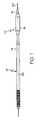
- FIG. 1is a side view of an embodiment of the invention wherein the tip is shown on a typical catheter;
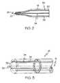
- FIG. 2is a close up side view of an embodiment of the invention
- FIG. 3is a partial cut-away perspective view of an embodiment of the catheter tip of the present invention.
- FIG. 4is a partial cut-away perspective view of another embodiment of the catheter tip of the present invention.
- FIG. 5is a partial cut-away perspective view of another embodiment of the catheter tip of the present invention.
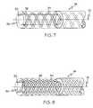
- FIG. 6is a partial cut-away perspective view of another embodiment of the catheter tip of the present invention.
- FIG. 7is a partial cut-away perspective view of another embodiment of the catheter tip of the present invention.
- FIG. 8is a partial cut-away perspective view of another embodiment of the catheter tip of the present invention.
- FIG. 9is a perspective view of another embodiment of the catheter tip of the present invention.
- FIG. 10is a perspective view of another embodiment of the catheter tip of the present invention.
- FIG. 11is a detailed partially cut-away view of another embodiment of the catheter tip of the present invention.
- FIG. 12is a cross-sectional view of another embodiment of the catheter tip of the present invention.
- FIG. 13is a cross-sectional view of another embodiment of the catheter tip of the present invention.
- the present inventionmay be embodied in a catheter, indicated generally at 10 .
- Catheter 10may be any type of catheter such as a balloon catheter, a stent delivery catheter, a guide catheter or other type.
- the cathetermay have a fixed wire, OTW, rapid exchange or other type of configuration as desired.
- the catheter 10has a body 12 consisting of a shaft 14 which extends distally to a distal end or tip 16 .
- the catheter 10may include an inflation member or balloon 18 disposed about the shaft 14 proximal to the distal tip 16 .
- the inflation membermay be configured to deliver or seat a medical device such as a stent and may be equipped with one or more stent retaining sleeves, such as is described in U.S. application Ser. No. 09/829,295 to Yang, filed Apr. 9, 2001, the entire contents of which being incorporated herein by reference.
- catheter 10may be any type of catheter capable of being inserted into and advanced through a body lumen.
- FIG. 1shows a typical catheter 10 which is advanced through the body along a guide wire 20 .
- the catheter or at least a portion thereofdefines a lumen 25 through which the guide wire 20 or other object may be advanced.
- lumen 25may have significant diameter to allow a second catheter (not shown) to be advanced through the lumen 25 .
- the end 24 of the distal tip 16 of catheter 10includes a distal opening 22 (shown in FIG. 2) through which the guide wire 20 passes out of the lumen 25 .
- the size of the opening 22may be varied.
- the opening 22may have a diameter sufficient to allow a dilitation catheter or other type of catheter to pass therethrough.
- the opening and lumenmay be absent from the tip 16 .
- FIG. 2a close up view of an embodiment of the tip 16 is shown.
- the tip 16has a unique construction which allows the tip to remain functionally rigid so that the catheter 10 may be advanced through a vessel but which is also soft and flexible to help prevent potential damage to the vessel wall as the catheter is advanced.
- the improved unique physical characteristics of the tip 16are the result of the unique composite construction of the tip 16 which includes a combination of a matrix 33 composed of a first material 30 , and one or more stripes 35 composed of a stripe material 34 .
- the matrix material 30may have a hardness value which on the Shore durometer scale is less than the hardness value of the stripe material 34 .
- the matrix material 30is formed into a generally tubular body 32 which provides the tip 16 with its shape as well as its inside surface 100 and outside surface 102 such as may be seen in FIGS. 9-10 and 12 .
- the tip 16is shown to include a matrix 33 and one or more strips 35 . It should be noted however, that the present invention is not limited to only the tip 16 of the catheter 10 such as is shown in FIG. 1 . As it may be desirable to provide additional portions of the catheter 10 with the unique physical properties of the invention, it is understood that the entire catheter 10 or portions thereof in addition to the tip 16 may be provided with the combination of materials described herein.
- the matrix material 30may be any elastomer material known which has a hardness as measured by a Shore D durometer of about 64D. In some embodiments the hardness of the first material 30 may be between about 25D to about 74D. In still some other embodiments the hardness of the first material 30 may be about 30D to about 65D.
- the stripe material 34may be any material having a durometer hardness of about 55D to about 84D. In at least one embodiment of the invention the matrix material 30 has a hardness of 55D and the stripe material 34 has a hardness of 80D.
- the combination of matrix 33 and the comparatively hard stripes 35provides the tip 16 with improved flexibility for negotiating the tortious confines of the vasculature but also with improved longitudinal rigidity for advancing the tip 16 with improved push-ability.
- tip 16has performance characteristics similar to a 74A rubber for purposes of radial expansion, and 60D for purposes of longitudinal elongation.
- tip 16is that when the catheter 16 is used with a guide wire 20 , the harder stripes 35 restrict the elasticity of the matrix 33 such that when the tip 16 travels along the guide wire 20 or when another catheter is passed through the opening 22 , the tip 16 remains longitudinally rigid but is able to expand radially to allow for improved passage of the wire and/or catheter therethrough.
- the number of stripes 35may vary from a single stripe 35 such as may be seen in FIG. 11 to several stripes as shown in FIGS. 2-10 and 12 - 13 .
- the stripes 35may have a wide variety of orientations and positions relative to the matrix 33 .
- the embodiments depicted in FIGS. 2-10are just several examples of the configurations which may be utilized.
- One of skill in the artwill recognize that the present invention is also directed to all other configurations, orientations and numbers of strips 35 which may be utilized with the matrix 33 .
- the stripes 35appear to be a surface feature applied to the matrix 33 .
- the stripes 35may be partially imbedded within the matrix 33 or may share the same thickness as the matrix 33 .
- the stripes 35may be a braid of multiple fibers of hardened material 34 or may be a coating of hardened material 34 .
- the stripes 35are uniformly distributed about the circumference of the tip 16 , however other dispersement patterns are possible, examples of which are described in greater detail below.
- the stripesalso extend the entire length of the tip 16 and may be configured to gradually reduce in width as they tapper toward the end 24 . Such a configuration allows for uniform distribution of the first material 30 and second material 34 through out the length of the tip 16 . However, if it is desired to provide a tip 16 with an end 24 which is harder or softer than the remaining portion of the tip 16 , the width of the stripes 35 may be increased or reduced respectively.
- the stripes 35are imbedded within the matrix 33 and extend the entire length of the tip 16 .
- the stripes 35prior to being mounted on the stent delivery catheter the stripes 35 are oriented within the matrix 33 to be parallel to the longitudinal axis 13 of the tip 16 .
- a pair of stripes 35are configured within the matrix 33 in opposing zig-zag patterns.
- the stripes 35extend from a respective end 24 or 26 of the tip 16 and extend to a middle portion 15 of the tip 16 and then extend back toward the opposing end in an alternating pattern.
- the zig-zag configured stripes 35may be made up of individual members 51 whose ends are adjacent to one another.
- a single zig-zag stripe 35may be employed which is a continuous stripe having a plurality of folds 41 at the tip ends 24 and 26 to provide the pattern shown.
- the stripes 35are also in a zig-zag pattern.
- the stripe 35 (or members 51 thereof)are angularly disposed relative to the longitudinal axis 13 of the tip 16 .
- the stripes 35 (or lengths 51 thereof)fully extend from one end 24 of the tip 16 to the other 26 .
- each of the plurality of stripes 35have a random length which may or may not extend the entire length of the tip 16 .
- the individual stripes 35may or may not be parallel to the longitudinal axis 13 , and may have a completely random orientation relative to the longitudinal axis 13 .
- the stripes 35may or may not be arranged in a uniform pattern such as is shown in the previously described embodiments.
- a pair of strands 35are shown in a double helix configuration wherein each strand 35 is helically disposed relative to the longitudinal axis 13 in opposing directions.
- a plurality of helically disposed strands 35are imbedded in the matrix 33 , wherein each of the strands 35 is oriented in the same direction.
- FIGS. 9-10embodiments of the tip 16 are shown wherein the stripes 35 need not be completely imbedded within the matrix 33 .
- the stripes 35are engaged to the inner surface 100 of the matrix 33
- the stripes 35are engaged to the outer surface 102 of the matrix 33 .
- the matrix 33may partially surround the stripes 35 .
- the stripes 35may be secured to the respective surface 100 and 102 in a variety of manners. For example, chemical adhesives, heat welding by laser or other means, chemical welding, etc, or other securing methods may all be used to secure the stripes 35 to the respective surfaces 100 and 102 of the matrix 33 .
- the matrix material 30 and the stripe material 34are coextruded. It should also be noted that in an alternative embodiment one or more stripes may be engaged to the inner surface of the matrix, the outer surface of the matrix, and/or imbedded within the matrix or any combination thereof. Regardless of the position of the stripes within the matrix or on of its surfaces, the stripes may be positioned in any of the variety of configurations and orientations described herein.
- the matrix material 30may be selected from a wide variety of substances.
- the matrixmay include but is not limited to, one or more of the following substances: soft grade polyester/polyether elastomers such as ArnitelTM available from DSM Engineering, polyurethane-polyether polymers, such as TecothaneTM available from Thermedics, Inc.; polyester-polyurethanes, such as PellethaneTM sold by Dow Chemical; polyester-polyurethanes, such as EstaneTM sold by BF Goodrich; polyether block amides (PEBA), such as PebaxTM available from Elf Atochem; and styrene-butadien-styrene triblock copolymers such as KratonTM sold by Shell Chemical company.
- soft grade polyester/polyether elastomerssuch as ArnitelTM available from DSM Engineering, polyurethane-polyether polymers, such as TecothaneTM available from Thermedics, Inc.
- styrenic block copolymerspolyurethanes, silicone rubber, natural rubber, copolyesters, polyamides, EPDM rubber/polyolefin, nitril rubber/PVC, fluoroelastomers, butyl rubber, epichlorohydrin, soft block copolymers, and any combinations thereof.
- the stripe material 34may also be selected from a wide range of materials.
- the stripe material 34may be include, but is not limited to, one or more of the following substances: polyethylene terephthalate (PET), polyethylene naphthalate (PEN) polybutylene terephthalate (PBT), polytrimethylene terephthalate (PTT), engineering thermoplastic polyurethanes, fluoropolymers, polyester/polyether elastomers such as ArnitelTM available from DSM Engineering, polyurethane-polyether polymers, such as TecothaneTM 1055D or 1075D, TecoplastTM 470 both of which are available from Thermedics, Inc.; polyester-polyurethanes, such as EstaneTM 58170 sold by BF Goodrich; polyether block amides (PEBA), such as PebaxTM 7233 or 6333 both of which are available from Elf Atochem.
- PEBApolyether block amides
- stripe material 34materials which may also be used in the production of the stripe material 34 include, but are not limited to: polyolefins, polystyrene, polyvinyl chloride, acrylonitrile-butadiene-styrene polymers, polyacrylonitrile, polyacrylate, vinyl acetate polymer, cellulose plastics, polyurethanes, polyacetal, polyethers, polycarbonates, polyamides, polyphenylene sulfide, polyarylethersulfones, polyaryletherketones, polytetrafluoroethylene, polyamide copolymer, such as MXD6TM availible from Mitsubishi Gas Chemical Co., or CristamidTM availible from Atofina and any combinations thereof.
- polyolefinssuch as MXD6TM availible from Mitsubishi Gas Chemical Co., or CristamidTM availible from Atofina and any combinations thereof.
- the matrix and stripe materials 30 and 34are in no way exhaustive of the potential substances or combinations of substances which may be used.
- the matrix 30 and/or stripe material 34may incorporate a radiopaque substance to provide the tip 16 with improved radiopacity when advanced through the body.
- the present inventionis directed to a distal tip 16 or other portion of a catheter composed of any materials which have the qualities previously described for the respective materials 30 and 34 .
- the tip 16may be embodied in a wide range of striped configurations. As may be seen in FIG. 11, the stripes 35 themselves may also be provided in a variety of designs. In FIG. 11, a close-up view of a stripe 35 is shown within the surrounding matrix 33 .
- the stripe 35is made up of a plurality of interwoven fibers 40 which are woven together to form a braid structure 42 .
- the braided configuration of the stripe 35provides the tip 16 with a stripe or stripes 35 that may be substantially stronger than a single monofilament fiber 40 , while maintaining the desired hardness and flexibility characteristics of the stripe material 34 .
- tip 16 with one or more braids 42 of a given stripe material 34 shownwill have improved longitudinal strength characteristics without a reduction in flexibility which may have resulted if a harder material 34 were used to form a monofilament stripe.
- the stripe 35is a braid 42 of several fibers 40
- the individual fibersmay be materials having different characteristics.
- the matrix 33may also be provided in alternative forms.
- FIG. 12an embodiment of the tip 16 is shown wherein the matrix material 30 is actually a combination of materials.
- the matrix 33is a combination of an inner material 46 and an outer material 48 , with a plurality of stripes 35 sandwiched in between. Providing the matrix 33 with a combination of materials may provide the tip 16 with even greater flexibility without substantial reductions in push-ability.
- the inner material 46may be a layer of hydrophobic elastomer such as a Siloxane-Polyurethane copolymer which has a relatively low surface friction and less tack, thereby providing the tip 16 with a reduced frictional interface between the inner surface 100 and a guide wire or catheter passing thereagainst.
- the outer material 48may be comprised of a hydrophilic elastomer, such as hydrophilic polyurethane, which may provide the outer surface 102 of the tip 16 with wet lubricity characteristics when the outer surface is in contact with bodily fluids, such as when the catheter is advanced through a vessel.
- the inner material 46 and the outer material 48 of the tip 16may be provided with a wide variety of different or similar material combinations.
- FIG. 13another embodiment is shown wherein the matrix 33 is comprised of three layers, with the stripes 35 completely imbedded within an intermediate layer 50 , which is in turn sandwiched between the outer material 48 and inner material 46 .
- Such an embodimentmay be useful when the materials selected for the outer material 48 and inner material 46 do not tend to readily bond together and an intermediate material 50 is used to provide a material which the outer material 48 and inner material 46 may be more readily bonded to.
- the matrix 33is not limited to only the one, two or three layer configurations described herein, but may be embodied in a wide range of configurations having a plurality of layers of one or more materials.
- the tip 16may be provided in a wide range of shapes and sizes.
- the tipmay have surface features such as dimples or troughs, or may have structural alterations such as through holes or ports, for altering the retraction characteristics of the tip.
- Tip 16may include additional layers such as internal or external coatings, such as may be known in the art for improving the tip's as well as the catheter's performance.
- any dependent claim which followsshould be taken as alternatively written in a multiple dependent form from all prior claims which possess all antecedents referenced in such dependent claim if such multiple dependent format is an accepted format within the jurisdiction (e.g. each claim depending directly from claim 1 should be alternatively taken as depending from all previous claims).
Landscapes
- Health & Medical Sciences (AREA)
- Life Sciences & Earth Sciences (AREA)
- Animal Behavior & Ethology (AREA)
- General Health & Medical Sciences (AREA)
- Biomedical Technology (AREA)
- Heart & Thoracic Surgery (AREA)
- Hematology (AREA)
- Engineering & Computer Science (AREA)
- Veterinary Medicine (AREA)
- Anesthesiology (AREA)
- Public Health (AREA)
- Biophysics (AREA)
- Pulmonology (AREA)
- Vascular Medicine (AREA)
- Materials For Medical Uses (AREA)
- Media Introduction/Drainage Providing Device (AREA)
Abstract
Description
Not Applicable
Not Applicable
This invention relates to the field of intravascular medical devices, and more particularly to the field of catheters such as angioplasty, neurological and guide catheters, among others, which may be used in various medical procedures such as percutaneous transluminal angioplasty (PTA), percutaneous transluminal coronary angioplasty (PTCA) as well as in procedures involving the placement of medicines and medical devices within the body. The present invention is directed to all forms of catheters which may be advanced through a body lumen or vessel. Some examples of catheters are over-the-wire (OTW) catheters, such as are described in U.S. Pat. No. 5,047,045; single-operator-exchange (SOE) balloon catheters, such as are described in U.S. Pat. No. 5,156,594 and U.S. Pat. No. 5,549,552. Other examples of catheters which may incorporate the unique features of the present invention are also described in U.S. Pat. No. 5,938,653, U.S. Pat. No. 5,897,537, among others.
The entire content of all of the patents listed within the present patent application are incorporated herein by reference.
Intravascular diseases are commonly treated by relatively non-invasive techniques such as PTA and PTCA. These angioplasty techniques typically involve the use of a balloon catheter. In these procedures, a balloon catheter is advanced through the vasculature of a patient such that the balloon is positioned proximate a restriction in a diseased vessel. The balloon is then inflated and the restriction in the vessel is opened. In other uses a catheter may be used to delivery an endoprosthesis such as a stent, graft, vena cava filter or other implantable device. Where an implantable device is to be delivered into a body lumen the catheter may include one or more inflatable portions or balloons.
Many procedures make use of a guide catheter positioned within the vascular system of a patient. The guiding catheter assists in transporting a balloon dilation catheter, or other form of treatment catheter, to the portion of the vessel requiring treatment or inspection. The guide catheter is urged through the vasculature of the patient until its distal end is proximate the restriction. The balloon catheter may then be fed through a lumen in the guide catheter.
Whether an individual procedure utilizes a guide catheter or simply requires the use of a solitary dilitation or medical device delivery catheter, catheters typically must possess a level of rigidity which will allow it to traverse tortious pathways through blood vessels in a manner that minimizes trauma. The catheter must be capable of being advanced through the vascular system without folding or buckling despite application of longitudinal and/or rotational forces upon the catheter. Because many catheters have the desired rigidity, it is desirable to incorporate a relatively flexible and desirably atraumatic tip on the distal end of the catheter to avoid injury to the walls of the blood vessels as the otherwise comparatively rigid catheter is advanced therethrough.
The present invention provides a catheter with a novel tip or distal end which is sufficiently rigid to avoid kinking and bending as it advances through a lumen, but which is sufficiently soft and flexible such that the tip is less likely to cause trauma to vessel surfaces which it may contact.
The catheter tip may be provided with the desired characteristics by constructing the tip from a combination of at least two materials having different material characteristics such as hardness.
In at least one embodiment of the invention, the catheter tip comprises a first material or matrix and one or more stripes or segments of a second material, wherein the second material is harder than the first material.
As used herein, the term ‘hardness’ is used to define a differentiating feature between the first material and the second material. Hardness may be defined using the Shore scale of hardness wherein the second material may have a greater value on the Shore scale of hardness than that of the first material. However, the term ‘hardness’ as used herein may be used to denote a measurable difference between the first material and the second material other then that which may be indicated using a Shore hardness test. The hardness as defined by the Shore scale is considered to be a significant feature in differentiating between the first material and the second material, ‘hardness’ may also refer to concepts such flexibility, elasticity, tensile modulus, modulus of elasticity, as well as many other characteristics which may be different from one another.
The second material may be characterized as one or more stripes of material imbedded within or engaged to the first material. The stripes of material may be coextruded with the matrix or may be engaged to the matrix after formation of the first material. The stripes of the second material may be uniform in width along the length of the catheter tip. Alternatively the stripes may taper, be intermittent, or otherwise configured. Furthermore, the stripes may be disposed about the matrix in a variety of ways, such as for example, one or more stripes may be helically wound about the tip, multiple stripes may be longitudinally parallel throughout the length of the tip, a stripe or stripes may extend along the length of the tip and tapper toward or away from the end of the tip in increasing or decreasing width.
Other characteristics of the stripe or stripes of secondary material may also be varied relative to the first material matrix. For example, the second material may have a thickness equal to or different from the thickness of the first material.
The stripes of relatively hard secondary material may alternatively be characterized as one or more coatings applied to the surface of the first material.
The second material may also be characterized as one or more fibers or braids of fiber of a predetermined material or combination of materials. The fibers may be oriented relative to the longitudinal axis of the catheter tip in a variety of patterns. For example the fibers may be substantially parallel to the longitudinal axis of the angled relative thereto, helically or otherwise disposed thereabout, etc.
In at least one embodiment of the invention, the stripe(s) of second material may be disposed about the inside and/or outside of the catheter tip.
In yet another embodiment of the invention, the stripes of a second material may be fully enclosed, or “sandwiched” within the matrix of the first material.
In still another embodiment of the invention the matrix of the catheter tip, i.e. the first material, may itself be comprised of a variety of materials. In such an embodiment the stripe(s) may be enclosed between an inside layer of material and an outside layer of material, wherein the inside material and the outside material are different from one another. In such an embodiment the stripe(s) of second material remain harder than the combined layers of first material.
A detailed description of the invention is hereafter described with specific reference being made to the drawings in which:
FIG. 1 is a side view of an embodiment of the invention wherein the tip is shown on a typical catheter;
FIG. 2 is a close up side view of an embodiment of the invention;
FIG. 3 is a partial cut-away perspective view of an embodiment of the catheter tip of the present invention;
FIG. 4 is a partial cut-away perspective view of another embodiment of the catheter tip of the present invention;
FIG. 5 is a partial cut-away perspective view of another embodiment of the catheter tip of the present invention;
FIG. 6 is a partial cut-away perspective view of another embodiment of the catheter tip of the present invention;
FIG. 7 is a partial cut-away perspective view of another embodiment of the catheter tip of the present invention;
FIG. 8 is a partial cut-away perspective view of another embodiment of the catheter tip of the present invention;
FIG. 9 is a perspective view of another embodiment of the catheter tip of the present invention;
FIG. 10 is a perspective view of another embodiment of the catheter tip of the present invention;
FIG. 11 is a detailed partially cut-away view of another embodiment of the catheter tip of the present invention;
FIG. 12 is a cross-sectional view of another embodiment of the catheter tip of the present invention; and
FIG. 13 is a cross-sectional view of another embodiment of the catheter tip of the present invention.
In the various FIGS. 1-13 identical components are designated by the same reference numbers in the following description of various embodiments.
As may be seen in FIG. 1, the present invention may be embodied in a catheter, indicated generally at10.Catheter 10, may be any type of catheter such as a balloon catheter, a stent delivery catheter, a guide catheter or other type. The catheter may have a fixed wire, OTW, rapid exchange or other type of configuration as desired. Thecatheter 10 has abody 12 consisting of ashaft 14 which extends distally to a distal end ortip 16. In many embodiments thecatheter 10 may include an inflation member orballoon 18 disposed about theshaft 14 proximal to thedistal tip 16. The inflation member may be configured to deliver or seat a medical device such as a stent and may be equipped with one or more stent retaining sleeves, such as is described in U.S. application Ser. No. 09/829,295 to Yang, filed Apr. 9, 2001, the entire contents of which being incorporated herein by reference.
As indicated above,catheter 10 may be any type of catheter capable of being inserted into and advanced through a body lumen. FIG. 1 shows atypical catheter 10 which is advanced through the body along aguide wire 20. In order forguide wire 20 to pass through thecatheter 10, the catheter or at least a portion thereof, defines alumen 25 through which theguide wire 20 or other object may be advanced. Where thecatheter 10 is a guide catheter,lumen 25 may have significant diameter to allow a second catheter (not shown) to be advanced through thelumen 25.
In the embodiment shown, theend 24 of thedistal tip 16 ofcatheter 10 includes a distal opening22 (shown in FIG. 2) through which theguide wire 20 passes out of thelumen 25. As suggested above, the size of theopening 22 may be varied. For example, where thecatheter 10 is a guide catheter, theopening 22 may have a diameter sufficient to allow a dilitation catheter or other type of catheter to pass therethrough. In some alternative embodiments, the opening and lumen may be absent from thetip 16.
In FIG. 2 a close up view of an embodiment of thetip 16 is shown. Thetip 16 has a unique construction which allows the tip to remain functionally rigid so that thecatheter 10 may be advanced through a vessel but which is also soft and flexible to help prevent potential damage to the vessel wall as the catheter is advanced. The improved unique physical characteristics of thetip 16 are the result of the unique composite construction of thetip 16 which includes a combination of amatrix 33 composed of afirst material 30, and one ormore stripes 35 composed of astripe material 34.
Thematrix material 30 may have a hardness value which on the Shore durometer scale is less than the hardness value of thestripe material 34. Thematrix material 30 is formed into a generally tubular body32 which provides thetip 16 with its shape as well as itsinside surface 100 and outsidesurface 102 such as may be seen in FIGS. 9-10 and12.
In the various embodiments shown in FIGS. 2-13, thetip 16 is shown to include amatrix 33 and one or more strips35. It should be noted however, that the present invention is not limited to only thetip 16 of thecatheter 10 such as is shown in FIG.1. As it may be desirable to provide additional portions of thecatheter 10 with the unique physical properties of the invention, it is understood that theentire catheter 10 or portions thereof in addition to thetip 16 may be provided with the combination of materials described herein.
Thematrix material 30 may be any elastomer material known which has a hardness as measured by a Shore D durometer of about 64D. In some embodiments the hardness of thefirst material 30 may be between about 25D to about 74D. In still some other embodiments the hardness of thefirst material 30 may be about 30D to about 65D. Thestripe material 34 may be any material having a durometer hardness of about 55D to about 84D. In at least one embodiment of the invention thematrix material 30 has a hardness of 55D and thestripe material 34 has a hardness of 80D.
In the various embodiments shown, the combination ofmatrix 33 and the comparativelyhard stripes 35 provides thetip 16 with improved flexibility for negotiating the tortious confines of the vasculature but also with improved longitudinal rigidity for advancing thetip 16 with improved push-ability. As an example of the improved characteristics of thetip 16, in at least one tested embodiment,tip 16 has performance characteristics similar to a 74A rubber for purposes of radial expansion, and 60D for purposes of longitudinal elongation.
An additional benefit provided by the unique hybrid construction oftip 16 is that when thecatheter 16 is used with aguide wire 20, theharder stripes 35 restrict the elasticity of thematrix 33 such that when thetip 16 travels along theguide wire 20 or when another catheter is passed through theopening 22, thetip 16 remains longitudinally rigid but is able to expand radially to allow for improved passage of the wire and/or catheter therethrough.
In the various embodiments show and described herein, the number ofstripes 35 may vary from asingle stripe 35 such as may be seen in FIG. 11 to several stripes as shown in FIGS. 2-10 and12-13. In FIGS. 2-10 it may be seen that thestripes 35 may have a wide variety of orientations and positions relative to thematrix 33. The embodiments depicted in FIGS. 2-10 are just several examples of the configurations which may be utilized. One of skill in the art will recognize that the present invention is also directed to all other configurations, orientations and numbers ofstrips 35 which may be utilized with thematrix 33.
In FIG. 2, thestripes 35 appear to be a surface feature applied to thematrix 33. However, thestripes 35 may be partially imbedded within thematrix 33 or may share the same thickness as thematrix 33. Thestripes 35 may be a braid of multiple fibers ofhardened material 34 or may be a coating ofhardened material 34. In the embodiment shown thestripes 35 are uniformly distributed about the circumference of thetip 16, however other dispersement patterns are possible, examples of which are described in greater detail below. The stripes also extend the entire length of thetip 16 and may be configured to gradually reduce in width as they tapper toward theend 24. Such a configuration allows for uniform distribution of thefirst material 30 andsecond material 34 through out the length of thetip 16. However, if it is desired to provide atip 16 with anend 24 which is harder or softer than the remaining portion of thetip 16, the width of thestripes 35 may be increased or reduced respectively.
In FIG. 3, thestripes 35 are imbedded within thematrix 33 and extend the entire length of thetip 16. In the present embodiment, prior to being mounted on the stent delivery catheter thestripes 35 are oriented within thematrix 33 to be parallel to thelongitudinal axis 13 of thetip 16.
In the embodiment shown in FIG. 4, a pair ofstripes 35 are configured within thematrix 33 in opposing zig-zag patterns. Thestripes 35 extend from arespective end tip 16 and extend to amiddle portion 15 of thetip 16 and then extend back toward the opposing end in an alternating pattern. In the embodiment shown, the zig-zag configuredstripes 35 may be made up ofindividual members 51 whose ends are adjacent to one another. Alternatively, a single zig-zag stripe 35 may be employed which is a continuous stripe having a plurality offolds 41 at the tip ends24 and26 to provide the pattern shown.
In FIG. 5, thestripes 35 are also in a zig-zag pattern. The stripe35 (ormembers 51 thereof) are angularly disposed relative to thelongitudinal axis 13 of thetip 16. However, in FIG. 5 the stripes35 (orlengths 51 thereof) fully extend from oneend 24 of thetip 16 to the other26.
In FIG. 6, an embodiment of thetip 16 is shown wherein each of the plurality ofstripes 35 have a random length which may or may not extend the entire length of thetip 16. Additionally, theindividual stripes 35 may or may not be parallel to thelongitudinal axis 13, and may have a completely random orientation relative to thelongitudinal axis 13. It should also be noted that thestripes 35 may or may not be arranged in a uniform pattern such as is shown in the previously described embodiments.
In FIG. 7, a pair ofstrands 35 are shown in a double helix configuration wherein eachstrand 35 is helically disposed relative to thelongitudinal axis 13 in opposing directions. In the embodiment shown in FIG. 8 a plurality of helically disposedstrands 35 are imbedded in thematrix 33, wherein each of thestrands 35 is oriented in the same direction.
In FIGS. 9-10 embodiments of thetip 16 are shown wherein thestripes 35 need not be completely imbedded within thematrix 33. In FIG. 9, thestripes 35 are engaged to theinner surface 100 of thematrix 33, whereas in FIG. 10 thestripes 35 are engaged to theouter surface 102 of thematrix 33. Whether engaged to the inside100 oroutside surface 102, thematrix 33 may partially surround thestripes 35. Alternatively or in addition, thestripes 35 may be secured to therespective surface stripes 35 to therespective surfaces matrix 33. However, in a preferred embodiment, thematrix material 30 and thestripe material 34 are coextruded. It should also be noted that in an alternative embodiment one or more stripes may be engaged to the inner surface of the matrix, the outer surface of the matrix, and/or imbedded within the matrix or any combination thereof. Regardless of the position of the stripes within the matrix or on of its surfaces, the stripes may be positioned in any of the variety of configurations and orientations described herein.
In any of the embodiments described and/or depicted herein, thematrix material 30 may be selected from a wide variety of substances. For example, the matrix may include but is not limited to, one or more of the following substances: soft grade polyester/polyether elastomers such as Arnitel™ available from DSM Engineering, polyurethane-polyether polymers, such as Tecothane™ available from Thermedics, Inc.; polyester-polyurethanes, such as Pellethane™ sold by Dow Chemical; polyester-polyurethanes, such as Estane™ sold by BF Goodrich; polyether block amides (PEBA), such as Pebax™ available from Elf Atochem; and styrene-butadien-styrene triblock copolymers such as Kraton™ sold by Shell Chemical company. Other materials which may also be used in the production of thematrix material 30 include, but are not limited to styrenic block copolymers, polyurethanes, silicone rubber, natural rubber, copolyesters, polyamides, EPDM rubber/polyolefin, nitril rubber/PVC, fluoroelastomers, butyl rubber, epichlorohydrin, soft block copolymers, and any combinations thereof.
Thestripe material 34 may also be selected from a wide range of materials. For example thestripe material 34 may be include, but is not limited to, one or more of the following substances: polyethylene terephthalate (PET), polyethylene naphthalate (PEN) polybutylene terephthalate (PBT), polytrimethylene terephthalate (PTT), engineering thermoplastic polyurethanes, fluoropolymers, polyester/polyether elastomers such as Arnitel™ available from DSM Engineering, polyurethane-polyether polymers, such as Tecothane™ 1055D or 1075D, Tecoplast™ 470 both of which are available from Thermedics, Inc.; polyester-polyurethanes, such as Estane™ 58170 sold by BF Goodrich; polyether block amides (PEBA), such as Pebax™ 7233 or 6333 both of which are available from Elf Atochem. Other materials which may also be used in the production of thestripe material 34 include, but are not limited to: polyolefins, polystyrene, polyvinyl chloride, acrylonitrile-butadiene-styrene polymers, polyacrylonitrile, polyacrylate, vinyl acetate polymer, cellulose plastics, polyurethanes, polyacetal, polyethers, polycarbonates, polyamides, polyphenylene sulfide, polyarylethersulfones, polyaryletherketones, polytetrafluoroethylene, polyamide copolymer, such as MXD6™ availible from Mitsubishi Gas Chemical Co., or Cristamid™ availible from Atofina and any combinations thereof.
The above examples of the matrix andstripe materials matrix 30 and/orstripe material 34 may incorporate a radiopaque substance to provide thetip 16 with improved radiopacity when advanced through the body. The present invention is directed to adistal tip 16 or other portion of a catheter composed of any materials which have the qualities previously described for therespective materials
Thetip 16 may be embodied in a wide range of striped configurations. As may be seen in FIG. 11, thestripes 35 themselves may also be provided in a variety of designs. In FIG. 11, a close-up view of astripe 35 is shown within the surroundingmatrix 33. Thestripe 35 is made up of a plurality of interwovenfibers 40 which are woven together to form abraid structure 42. The braided configuration of thestripe 35 provides thetip 16 with a stripe orstripes 35 that may be substantially stronger than asingle monofilament fiber 40, while maintaining the desired hardness and flexibility characteristics of thestripe material 34. As a result,tip 16 with one ormore braids 42 of a givenstripe material 34 shown will have improved longitudinal strength characteristics without a reduction in flexibility which may have resulted if aharder material 34 were used to form a monofilament stripe. In addition, where thestripe 35 is abraid 42 ofseveral fibers 40, the individual fibers may be materials having different characteristics.
Not only are thestripes 35 variable in their characteristics, but thematrix 33 may also be provided in alternative forms. In FIG. 12, an embodiment of thetip 16 is shown wherein thematrix material 30 is actually a combination of materials. In the embodiment shown, thematrix 33 is a combination of aninner material 46 and anouter material 48, with a plurality ofstripes 35 sandwiched in between. Providing thematrix 33 with a combination of materials may provide thetip 16 with even greater flexibility without substantial reductions in push-ability. For example, theinner material 46 may be a layer of hydrophobic elastomer such as a Siloxane-Polyurethane copolymer which has a relatively low surface friction and less tack, thereby providing thetip 16 with a reduced frictional interface between theinner surface 100 and a guide wire or catheter passing thereagainst. Theouter material 48 may be comprised of a hydrophilic elastomer, such as hydrophilic polyurethane, which may provide theouter surface 102 of thetip 16 with wet lubricity characteristics when the outer surface is in contact with bodily fluids, such as when the catheter is advanced through a vessel. In addition to the example provided, it should be noted that theinner material 46 and theouter material 48 of thetip 16 may be provided with a wide variety of different or similar material combinations.
In FIG. 13 another embodiment is shown wherein thematrix 33 is comprised of three layers, with thestripes 35 completely imbedded within anintermediate layer 50, which is in turn sandwiched between theouter material 48 andinner material 46. Such an embodiment may be useful when the materials selected for theouter material 48 andinner material 46 do not tend to readily bond together and anintermediate material 50 is used to provide a material which theouter material 48 andinner material 46 may be more readily bonded to. Thematrix 33 is not limited to only the one, two or three layer configurations described herein, but may be embodied in a wide range of configurations having a plurality of layers of one or more materials.
Thetip 16 may be provided in a wide range of shapes and sizes. The tip may have surface features such as dimples or troughs, or may have structural alterations such as through holes or ports, for altering the retraction characteristics of the tip.Tip 16 may include additional layers such as internal or external coatings, such as may be known in the art for improving the tip's as well as the catheter's performance.
In addition to being directed to the specific combinations of features claimed below, the invention is also directed to embodiments having other combinations of the dependent features claimed below and other combinations of the features described above.
The above disclosure is intended to be illustrative and not exhaustive. This description will suggest many variations and alternatives to one of ordinary skill in this art. All these alternatives and variations are intended to be included within the scope of the claims where the term “comprising” means “including, but not limited to”. Those familiar with the art may recognize other equivalents to the specific embodiments described herein which equivalents are also intended to be encompassed by the claims.
Further, the particular features presented in the dependent claims can be combined with each other in other manners within the scope of the invention such that the invention should be recognized as also specifically directed to other embodiments having any other possible combination of the features of the dependent claims. For instance, for purposes of claim publication, any dependent claim which follows should be taken as alternatively written in a multiple dependent form from all prior claims which possess all antecedents referenced in such dependent claim if such multiple dependent format is an accepted format within the jurisdiction (e.g. each claim depending directly from claim1 should be alternatively taken as depending from all previous claims). In jurisdictions where multiple dependent claim formats are restricted, the following dependent claims should each be also taken as alternatively written in each singly dependent claim format which creates a dependency from a prior antecedent-possessing claim other than the specific claim listed in such dependent claim below (e.g. claim3 may be taken as alternatively dependent fromclaim 2; claim5 may be taken as alternatively dependent on claim3, claim6 may be taken as alternatively dependent from claim3; claim7 may be taken as alternatively dependent from claims3,5 or6; etc.).
Claims (13)
1. A catheter comprising:
a tubular catheter shaft, the tubular catheter shaft having a proximal portion and a distal portion, the distal portion having a distal tip engaged thereto, the distal tip having a different material composition than the catheter shaft, the distal tip comprising an inner matrix layer, an outer matrix layer and at least one stripe positioned between at least a portion of the inner matrix layer and the outer matrix layer, the at least one stripe being substantially parallel to a longitudinal axis of the distal tip, the inner matrix layer defined by at least one inner matrix material and the outer matrix layer defined by at least one outer matrix material different form the inner matrix material, and the at least one stripe defined by at least one stripe material, the at least one inner matrix material and at least one outer matrix material each having a predetermined hardness and the at least one stripe material having a predetermined hardness, the predetermined hardness of the at least one stripe material having a greater durometer value than the predetermined hardness of the at least one inner matrix material and at least one outer matrix material.
2. The catheter ofclaim 1 wherein the tubular catheter shaft an the distal tip define a common lumen.
3. The catheter ofclaim 1 wherein the least one stripe has a length substantially equal to that of the matrix.
4. The catheter ofclaim 1 wherein the at least one stripe is a plurality of stripes.
5. The catheter ofclaim 4 wherein each of the plurality of stripes is distributed between the inner matrix layer and the outer matrix layer in a uniform manner.
6. The catheter ofclaim 4 wherein each of the plurality of stripes has a uniform orientation relative to the longitudinal axis of the distal tip.
7. The catheter ofclaim 1 wherein the inner matrix layer has an outside surface, the at least one stripe being engaged to the outside surface of the inner matrix layer.
8. The catheter ofclaim 1 wherein the at least one inner matrix material and the at least one outer matrix material are each selected from as least one member of the group consisting of polyester/polyether elastomers, polyurethane polyether polymers, polyester-polyurethanes, polyester-polyurethanes, polyether block amides (PEBA), styrene-butadien-styrene triblock copolymers, styrenic block copolymers, polyurethanes, silicone rubber, natural rubber, copolyester, polyamides, EPDM rubber polyolefin, nitril rubber/PVC, fluoroelastomers, butyl rubber, epichlorohydrin, soft block copolymers, end any combinations thereof.
9. The catheter ofclaim 1 wherein the at least one stripe material is selected from at least one member of the group consisting of polyethylene terephthalate (PET), polyethylene naphthalate (PEN), polybutylene terephthalate (PBT), polytrimethylene terephthalate (PTT), engineering thermoplastic polyurethanes, fluoropolymers, polyester/polyether elastomers, polyurethane polyether polymers, polyester-polyurethanes, polyether block amides (PEBA), polyolefins, polystyrene, polyvinyl chloride, acrylonitrile-butadiene-styrene polymers, polyacrylonitrile, polyacrylate, vinyl acetate polymer, cellulose plastics, polyurethanes, polyacetal, polyethers, polycarbonate, polyamides, polyphenylene sulfide, polyarylethersulfones, polyaryletherketones, polytetrafluoroethylene, polyamide copolymer, and any combination thereof.
10. The catheter ofclaim 1 , wherein the at least one inner matrix material and the at least one outer matrix material each have a durometer hardness value in a range of about 25D to about 74D, and the at least one stripe material has a durometer hardness value in a range of about 55D to about 84D.
11. The catheter ofclaim 10 wherein the at least one inner matrix material and the at least one outer matrix material each have a durometer hardness value of about 55D, and the at least one stripe material has a durometer hardness value of about 80D.
12. The catheter ofclaim 1 wherein the catheter is selected from the group consisting of dilatation catheters, guide catheters, over-the-wire catheters, rapid exchange catheters, single-operator-exchange catheter, medical device delivery catheter, and any combinations thereof.
13. The catheter ofclaim 1 wherein at least a portion of the distal tip is radiopaque.
Priority Applications (8)
| Application Number | Priority Date | Filing Date | Title |
|---|---|---|---|
| US09/965,765US6814744B2 (en) | 2001-09-28 | 2001-09-28 | Balloon catheter with striped flexible tip |
| CA002457855ACA2457855C (en) | 2001-09-28 | 2002-06-06 | Balloon catheter with striped flexible tip |
| DE60224411TDE60224411T2 (en) | 2001-09-28 | 2002-06-06 | BALLOON CATHETER WITH STRIPED FLEXIBLE TIP |
| AT02739743TATE382390T1 (en) | 2001-09-28 | 2002-06-06 | BALLOON CATHETER WITH STRIPED FLEXIBLE TIP |
| ES02739743TES2299580T3 (en) | 2001-09-28 | 2002-06-06 | CATETER WITH BALL WITH FLEXIBLE POINT WITH STRIPS. |
| JP2003532121AJP4865188B2 (en) | 2001-09-28 | 2002-06-06 | Balloon catheter with striped flexible tip |
| EP02739743AEP1429830B1 (en) | 2001-09-28 | 2002-06-06 | Balloon catheter with striped flexible tip |
| PCT/US2002/018011WO2003028794A1 (en) | 2001-09-28 | 2002-06-06 | Balloon catheter with striped flexible tip |
Applications Claiming Priority (1)
| Application Number | Priority Date | Filing Date | Title |
|---|---|---|---|
| US09/965,765US6814744B2 (en) | 2001-09-28 | 2001-09-28 | Balloon catheter with striped flexible tip |
Publications (2)
| Publication Number | Publication Date |
|---|---|
| US20030065352A1 US20030065352A1 (en) | 2003-04-03 |
| US6814744B2true US6814744B2 (en) | 2004-11-09 |
Family
ID=25510462
Family Applications (1)
| Application Number | Title | Priority Date | Filing Date |
|---|---|---|---|
| US09/965,765Expired - LifetimeUS6814744B2 (en) | 2001-09-28 | 2001-09-28 | Balloon catheter with striped flexible tip |
Country Status (8)
| Country | Link |
|---|---|
| US (1) | US6814744B2 (en) |
| EP (1) | EP1429830B1 (en) |
| JP (1) | JP4865188B2 (en) |
| AT (1) | ATE382390T1 (en) |
| CA (1) | CA2457855C (en) |
| DE (1) | DE60224411T2 (en) |
| ES (1) | ES2299580T3 (en) |
| WO (1) | WO2003028794A1 (en) |
Cited By (17)
| Publication number | Priority date | Publication date | Assignee | Title |
|---|---|---|---|---|
| US20050267442A1 (en)* | 2004-05-27 | 2005-12-01 | Randolf Von Oepen | Catheter having main body portion with coil-defined guidewire passage |
| US20090287187A1 (en)* | 2008-05-07 | 2009-11-19 | Guided Delivery Systems Inc. | Deflectable guide |
| US7625353B2 (en) | 2004-05-27 | 2009-12-01 | Abbott Laboratories | Catheter having first and second guidewire tubes and overlapping stiffening members |
| US7628769B2 (en) | 2004-05-27 | 2009-12-08 | Abbott Laboratories | Catheter having overlapping stiffening members |
| US7658723B2 (en) | 2004-05-27 | 2010-02-09 | Abbott Laboratories | Catheter having plurality of stiffening members |
| US7785439B2 (en) | 2004-09-29 | 2010-08-31 | Abbott Laboratories Vascular Enterprises Limited | Method for connecting a catheter balloon with a catheter shaft of a balloon catheter |
| US7785318B2 (en) | 2004-05-27 | 2010-08-31 | Abbott Laboratories | Catheter having plurality of stiffening members |
| US7794448B2 (en) | 2004-05-27 | 2010-09-14 | Abbott Laboratories | Multiple lumen catheter and method of making same |
| US7815627B2 (en) | 2004-05-27 | 2010-10-19 | Abbott Laboratories | Catheter having plurality of stiffening members |
| DE102009023661A1 (en)* | 2009-06-03 | 2010-12-16 | Acandis Gmbh & Co. Kg | Medical catheter, medical functional element and arrangement comprising such a catheter and such a functional element |
| US20110172643A1 (en)* | 1998-06-11 | 2011-07-14 | Target Therapeutics, Inc. | Catheter with Composite Stiffener |
| US8323432B2 (en) | 2002-12-31 | 2012-12-04 | Abbott Laboratories Vascular Enterprises Limited | Catheter and method of manufacturing same |
| US20130006174A1 (en)* | 2011-06-30 | 2013-01-03 | Cordis Corporation | Medical tubing for catheters |
| US8608727B2 (en) | 2004-03-01 | 2013-12-17 | Smiths Medical Asd, Inc. | Delivery system and method |
| US20140107575A1 (en)* | 2001-06-26 | 2014-04-17 | Concentric Medical, Inc. | Balloon Catheter |
| US9173646B2 (en) | 2009-01-20 | 2015-11-03 | Guided Delivery Systems Inc. | Diagnostic catheters, guide catheters, visualization devices and chord manipulation devices, and related kits and methods |
| US9211389B2 (en) | 2009-12-07 | 2015-12-15 | Cook Medical Technologies Llc | Offset soft tip with proposed tooling |
Families Citing this family (12)
| Publication number | Priority date | Publication date | Assignee | Title |
|---|---|---|---|---|
| US6989025B2 (en) | 2002-10-04 | 2006-01-24 | Boston Scientific Scimed, Inc. | Extruded tubing with discontinuous striping |
| US20040267345A1 (en)* | 2003-06-30 | 2004-12-30 | Lorenzo Juan A. | Balloon catheter with self-centering tip |
| US20050177185A1 (en)* | 2004-02-05 | 2005-08-11 | Scimed Life Systems, Inc. | Counterwound coil for embolic protection sheath |
| US20060264903A1 (en)* | 2005-05-05 | 2006-11-23 | Walker Gregory L | SHG catheter and method of use |
| US20080275426A1 (en)* | 2007-05-03 | 2008-11-06 | Boston Scientific Scimed, Inc. | Flexible and Durable Tip |
| EP2244775B1 (en)* | 2007-12-26 | 2018-02-28 | Cook Medical Technologies LLC | Deployment catheter and delivery system thereof |
| US20090318863A1 (en)* | 2008-06-18 | 2009-12-24 | Boston Scientific Scimed, Inc. | Functional Balloon With Built in Lubricity or Drug Delivery System |
| JP5769992B2 (en)* | 2011-03-23 | 2015-08-26 | 株式会社グッドマン | catheter |
| WO2019146026A1 (en)* | 2018-01-25 | 2019-08-01 | 朝日インテック株式会社 | Catheter |
| KR102489167B1 (en)* | 2018-04-09 | 2023-01-17 | 보스톤 싸이엔티픽 싸이메드 인코포레이티드 | Stent delivery system with reduced deployment force |
| US20210220605A1 (en)* | 2020-01-21 | 2021-07-22 | Becton, Dickinson And Company | Tubular instrument and related devices and methods |
| WO2022215000A1 (en)* | 2021-04-07 | 2022-10-13 | Medtronic Vascular, Inc. | Catheter assembly with stiffener |
Citations (21)
| Publication number | Priority date | Publication date | Assignee | Title |
|---|---|---|---|---|
| US5047045A (en) | 1989-04-13 | 1991-09-10 | Scimed Life Systems, Inc. | Multi-section coaxial angioplasty catheter |
| US5156594A (en) | 1990-08-28 | 1992-10-20 | Scimed Life Systems, Inc. | Balloon catheter with distal guide wire lumen |
| EP0618059A1 (en) | 1993-03-31 | 1994-10-05 | Cordis Europa N.V. | Method for manufacturing an extrusion profile with variable properties along its length and catheters made in accordance with this method |
| US5484424A (en) | 1992-11-19 | 1996-01-16 | Celsa L.G. (Societe Anonyme) | Blood filtering device having a catheter with longitudinally variable rigidity |
| US5549552A (en) | 1995-03-02 | 1996-08-27 | Scimed Life Systems, Inc. | Balloon dilation catheter with improved pushability, trackability and crossability |
| WO1997037713A1 (en) | 1996-04-05 | 1997-10-16 | Csaba Truckai | Thin-walled and braid-reinforced catheter |
| US5891114A (en) | 1997-09-30 | 1999-04-06 | Target Therapeutics, Inc. | Soft-tip high performance braided catheter |
| US5897537A (en) | 1994-02-14 | 1999-04-27 | Scimed Life Systems, Inc. | Guide catheter having a plurality of filled distal grooves |
| US5935122A (en) | 1991-12-13 | 1999-08-10 | Endovascular Technologies, Inc. | Dual valve, flexible expandable sheath and method |
| US5938653A (en) | 1997-06-09 | 1999-08-17 | Scimed Life Systems, Inc. | Catheter having controlled flexibility and method of manufacture |
| US5976120A (en) | 1997-05-05 | 1999-11-02 | Micro Therapeutics, Inc. | Single segment microcatheter |
| EP0956878A2 (en) | 1998-05-14 | 1999-11-17 | Terumo Kabushiki Kaisha | Intravascular catheter and catheter-needle assembly |
| US6136006A (en)* | 1992-05-08 | 2000-10-24 | Boston Scientific Corporation | Apparatus for deliver and deployment of a stent |
| US6159187A (en) | 1996-12-06 | 2000-12-12 | Target Therapeutics, Inc. | Reinforced catheter with a formable distal tip |
| US6187130B1 (en) | 1999-05-26 | 2001-02-13 | Scimed Life Systems, Inc. | Method of creating a tip on a catheter |
| US6213995B1 (en) | 1999-08-31 | 2001-04-10 | Phelps Dodge High Performance Conductors Of Sc And Ga, Inc. | Flexible tubing with braided signal transmission elements |
| US6245053B1 (en) | 1998-11-09 | 2001-06-12 | Medtronic, Inc. | Soft tip guiding catheter and method of fabrication |
| US20010010247A1 (en) | 1995-06-07 | 2001-08-02 | Snow David W. | Cannula and method of manufacture and use |
| US20020038140A1 (en)* | 2000-09-22 | 2002-03-28 | Dachuan Yang | Hybrid elastomer sleeve for stent delivery |
| US20020038141A1 (en)* | 2000-09-22 | 2002-03-28 | Dachuan Yang | Sandwich striped sleeve for stent delively |
| US6503353B1 (en)* | 1996-05-13 | 2003-01-07 | Schneider (Usa) Inc. | Method for making a catheter |
- 2001
- 2001-09-28USUS09/965,765patent/US6814744B2/ennot_activeExpired - Lifetime
- 2002
- 2002-06-06ATAT02739743Tpatent/ATE382390T1/ennot_activeIP Right Cessation
- 2002-06-06JPJP2003532121Apatent/JP4865188B2/ennot_activeExpired - Fee Related
- 2002-06-06DEDE60224411Tpatent/DE60224411T2/ennot_activeExpired - Lifetime
- 2002-06-06CACA002457855Apatent/CA2457855C/ennot_activeExpired - Fee Related
- 2002-06-06ESES02739743Tpatent/ES2299580T3/ennot_activeExpired - Lifetime
- 2002-06-06EPEP02739743Apatent/EP1429830B1/ennot_activeExpired - Lifetime
- 2002-06-06WOPCT/US2002/018011patent/WO2003028794A1/enactiveIP Right Grant
Patent Citations (22)
| Publication number | Priority date | Publication date | Assignee | Title |
|---|---|---|---|---|
| US5047045A (en) | 1989-04-13 | 1991-09-10 | Scimed Life Systems, Inc. | Multi-section coaxial angioplasty catheter |
| US5156594A (en) | 1990-08-28 | 1992-10-20 | Scimed Life Systems, Inc. | Balloon catheter with distal guide wire lumen |
| US5935122A (en) | 1991-12-13 | 1999-08-10 | Endovascular Technologies, Inc. | Dual valve, flexible expandable sheath and method |
| US6136006A (en)* | 1992-05-08 | 2000-10-24 | Boston Scientific Corporation | Apparatus for deliver and deployment of a stent |
| US5484424A (en) | 1992-11-19 | 1996-01-16 | Celsa L.G. (Societe Anonyme) | Blood filtering device having a catheter with longitudinally variable rigidity |
| EP0618059A1 (en) | 1993-03-31 | 1994-10-05 | Cordis Europa N.V. | Method for manufacturing an extrusion profile with variable properties along its length and catheters made in accordance with this method |
| US5897537A (en) | 1994-02-14 | 1999-04-27 | Scimed Life Systems, Inc. | Guide catheter having a plurality of filled distal grooves |
| US5549552A (en) | 1995-03-02 | 1996-08-27 | Scimed Life Systems, Inc. | Balloon dilation catheter with improved pushability, trackability and crossability |
| US20010010247A1 (en) | 1995-06-07 | 2001-08-02 | Snow David W. | Cannula and method of manufacture and use |
| WO1997037713A1 (en) | 1996-04-05 | 1997-10-16 | Csaba Truckai | Thin-walled and braid-reinforced catheter |
| US6503353B1 (en)* | 1996-05-13 | 2003-01-07 | Schneider (Usa) Inc. | Method for making a catheter |
| US6159187A (en) | 1996-12-06 | 2000-12-12 | Target Therapeutics, Inc. | Reinforced catheter with a formable distal tip |
| US5976120A (en) | 1997-05-05 | 1999-11-02 | Micro Therapeutics, Inc. | Single segment microcatheter |
| US5938653A (en) | 1997-06-09 | 1999-08-17 | Scimed Life Systems, Inc. | Catheter having controlled flexibility and method of manufacture |
| US5891114A (en) | 1997-09-30 | 1999-04-06 | Target Therapeutics, Inc. | Soft-tip high performance braided catheter |
| EP0956878A2 (en) | 1998-05-14 | 1999-11-17 | Terumo Kabushiki Kaisha | Intravascular catheter and catheter-needle assembly |
| US6245053B1 (en) | 1998-11-09 | 2001-06-12 | Medtronic, Inc. | Soft tip guiding catheter and method of fabrication |
| US6187130B1 (en) | 1999-05-26 | 2001-02-13 | Scimed Life Systems, Inc. | Method of creating a tip on a catheter |
| US6213995B1 (en) | 1999-08-31 | 2001-04-10 | Phelps Dodge High Performance Conductors Of Sc And Ga, Inc. | Flexible tubing with braided signal transmission elements |
| US20020038140A1 (en)* | 2000-09-22 | 2002-03-28 | Dachuan Yang | Hybrid elastomer sleeve for stent delivery |
| US20020038141A1 (en)* | 2000-09-22 | 2002-03-28 | Dachuan Yang | Sandwich striped sleeve for stent delively |
| US6554841B1 (en)* | 2000-09-22 | 2003-04-29 | Scimed Life Systems, Inc. | Striped sleeve for stent delivery |
Cited By (28)
| Publication number | Priority date | Publication date | Assignee | Title |
|---|---|---|---|---|
| US20110172643A1 (en)* | 1998-06-11 | 2011-07-14 | Target Therapeutics, Inc. | Catheter with Composite Stiffener |
| US8795255B2 (en) | 1998-06-11 | 2014-08-05 | Boston Scientific Scimed, Inc. | Catheter with composite stiffener |
| US8317772B2 (en)* | 1998-06-11 | 2012-11-27 | Target Therapeutics, Inc. | Catheter with composite stiffener |
| US20140107575A1 (en)* | 2001-06-26 | 2014-04-17 | Concentric Medical, Inc. | Balloon Catheter |
| US8323432B2 (en) | 2002-12-31 | 2012-12-04 | Abbott Laboratories Vascular Enterprises Limited | Catheter and method of manufacturing same |
| US8608728B2 (en) | 2004-03-01 | 2013-12-17 | Smiths Medical Asd, Inc. | Delivery system and method |
| US8608727B2 (en) | 2004-03-01 | 2013-12-17 | Smiths Medical Asd, Inc. | Delivery system and method |
| US7785318B2 (en) | 2004-05-27 | 2010-08-31 | Abbott Laboratories | Catheter having plurality of stiffening members |
| US7628769B2 (en) | 2004-05-27 | 2009-12-08 | Abbott Laboratories | Catheter having overlapping stiffening members |
| US7815627B2 (en) | 2004-05-27 | 2010-10-19 | Abbott Laboratories | Catheter having plurality of stiffening members |
| US7527606B2 (en) | 2004-05-27 | 2009-05-05 | Abbott Laboratories | Catheter having main body portion with coil-defined guidewire passage |
| US20050267442A1 (en)* | 2004-05-27 | 2005-12-01 | Randolf Von Oepen | Catheter having main body portion with coil-defined guidewire passage |
| US7794448B2 (en) | 2004-05-27 | 2010-09-14 | Abbott Laboratories | Multiple lumen catheter and method of making same |
| US7658723B2 (en) | 2004-05-27 | 2010-02-09 | Abbott Laboratories | Catheter having plurality of stiffening members |
| US7625353B2 (en) | 2004-05-27 | 2009-12-01 | Abbott Laboratories | Catheter having first and second guidewire tubes and overlapping stiffening members |
| US8092634B2 (en) | 2004-09-29 | 2012-01-10 | Abbott Laboratories Vascular Enterprises Limited | Method for connecting a catheter balloon with a catheter shaft of a balloon catheter |
| US7785439B2 (en) | 2004-09-29 | 2010-08-31 | Abbott Laboratories Vascular Enterprises Limited | Method for connecting a catheter balloon with a catheter shaft of a balloon catheter |
| US8096985B2 (en) | 2008-05-07 | 2012-01-17 | Guided Delivery Systems Inc. | Deflectable guide |
| US20090287187A1 (en)* | 2008-05-07 | 2009-11-19 | Guided Delivery Systems Inc. | Deflectable guide |
| US10363392B2 (en) | 2008-05-07 | 2019-07-30 | Ancora Heart, Inc. | Deflectable guide |
| US9173646B2 (en) | 2009-01-20 | 2015-11-03 | Guided Delivery Systems Inc. | Diagnostic catheters, guide catheters, visualization devices and chord manipulation devices, and related kits and methods |
| US10625046B2 (en) | 2009-01-20 | 2020-04-21 | Ancora Heart, Inc. | Diagnostic catheters, guide catheters, visualization devices and chord manipulation devices, and related kits and methods |
| US11202883B2 (en) | 2009-01-20 | 2021-12-21 | Ancora Heart, Inc. | Diagnostic catheters, guide catheters, visualization devices and chord manipulation devices, and related kits and methods |
| US11980722B2 (en) | 2009-01-20 | 2024-05-14 | Ancora Heart, Inc. | Diagnostic catheters, guide catheters, visualization devices and chord manipulation devices, and related kits and methods |
| DE102009023661A1 (en)* | 2009-06-03 | 2010-12-16 | Acandis Gmbh & Co. Kg | Medical catheter, medical functional element and arrangement comprising such a catheter and such a functional element |
| US9211389B2 (en) | 2009-12-07 | 2015-12-15 | Cook Medical Technologies Llc | Offset soft tip with proposed tooling |
| US20130006174A1 (en)* | 2011-06-30 | 2013-01-03 | Cordis Corporation | Medical tubing for catheters |
| US9555165B2 (en)* | 2011-06-30 | 2017-01-31 | Cordis Corporation | Medical tubing for catheters |
Also Published As
| Publication number | Publication date |
|---|---|
| CA2457855A1 (en) | 2003-04-10 |
| EP1429830A1 (en) | 2004-06-23 |
| DE60224411D1 (en) | 2008-02-14 |
| CA2457855C (en) | 2009-12-08 |
| ATE382390T1 (en) | 2008-01-15 |
| DE60224411T2 (en) | 2008-05-21 |
| JP4865188B2 (en) | 2012-02-01 |
| JP2005503898A (en) | 2005-02-10 |
| WO2003028794A1 (en) | 2003-04-10 |
| ES2299580T3 (en) | 2008-06-01 |
| US20030065352A1 (en) | 2003-04-03 |
| EP1429830B1 (en) | 2008-01-02 |
Similar Documents
| Publication | Publication Date | Title |
|---|---|---|
| US6814744B2 (en) | Balloon catheter with striped flexible tip | |
| EP1549377B1 (en) | Extruded tubing with discontinuous striping | |
| JP5684594B2 (en) | Catheter assembly | |
| US6436090B1 (en) | Multi lumen catheter shaft | |
| US7713259B2 (en) | Guiding catheter shaft with improved radiopacity on the wire braid | |
| CA2531897C (en) | Catheter with sheathed hypotube | |
| US6740073B1 (en) | Guiding catheter reinforcement with angled distal end | |
| EP1683540A1 (en) | Balloon Catheter having a soft distal tip | |
| AU2437601A (en) | Catheter having a soft distal tip | |
| CA2675209A1 (en) | Rapid-exchange balloon catheter shaft and method | |
| WO1999017829A1 (en) | Radiopaque catheter and method of manufacture thereof | |
| WO2019009809A1 (en) | Drug delivery balloon catheter | |
| CN114010915B (en) | Medicine elution saccule | |
| EP3205365B1 (en) | Medical elongated body and balloon catheter | |
| WO2015065491A1 (en) | Length adjustable balloon catheter | |
| JP4833039B2 (en) | catheter | |
| JP4914282B2 (en) | Catheter with pushability | |
| WO2010060888A1 (en) | Medical balloon catheter with hollow wire cable rope guidewire duct | |
| JP2008264119A (en) | Catheter with pressing property |
Legal Events
| Date | Code | Title | Description |
|---|---|---|---|
| AS | Assignment | Owner name:SCIMED LIFE SYSTEMS, INC., MINNESOTA Free format text:ASSIGNMENT OF ASSIGNORS INTEREST;ASSIGNORS:YANG, DACHUAN;MILLER, PAUL J.;REEL/FRAME:012220/0711;SIGNING DATES FROM 20010918 TO 20010919 | |
| FEPP | Fee payment procedure | Free format text:PAYOR NUMBER ASSIGNED (ORIGINAL EVENT CODE: ASPN); ENTITY STATUS OF PATENT OWNER: LARGE ENTITY | |
| STCF | Information on status: patent grant | Free format text:PATENTED CASE | |
| AS | Assignment | Owner name:BOSTON SCIENTIFIC SCIMED, INC., MINNESOTA Free format text:CHANGE OF NAME;ASSIGNOR:SCIMED LIFE SYSTEMS, INC.;REEL/FRAME:018505/0868 Effective date:20050101 Owner name:BOSTON SCIENTIFIC SCIMED, INC.,MINNESOTA Free format text:CHANGE OF NAME;ASSIGNOR:SCIMED LIFE SYSTEMS, INC.;REEL/FRAME:018505/0868 Effective date:20050101 | |
| FPAY | Fee payment | Year of fee payment:4 | |
| FPAY | Fee payment | Year of fee payment:8 | |
| FPAY | Fee payment | Year of fee payment:12 |