US6814736B2 - Methods for injecting flowable materials into bones - Google Patents
Methods for injecting flowable materials into bonesDownload PDFInfo
- Publication number
- US6814736B2 US6814736B2US10/016,339US1633901AUS6814736B2US 6814736 B2US6814736 B2US 6814736B2US 1633901 AUS1633901 AUS 1633901AUS 6814736 B2US6814736 B2US 6814736B2
- Authority
- US
- United States
- Prior art keywords
- dispensing end
- cement
- nozzle assembly
- tube
- bone
- Prior art date
- Legal status (The legal status is an assumption and is not a legal conclusion. Google has not performed a legal analysis and makes no representation as to the accuracy of the status listed.)
- Expired - Fee Related, expires
Links
Images


Classifications
- A—HUMAN NECESSITIES
- A61—MEDICAL OR VETERINARY SCIENCE; HYGIENE
- A61B—DIAGNOSIS; SURGERY; IDENTIFICATION
- A61B17/00—Surgical instruments, devices or methods
- A61B17/56—Surgical instruments or methods for treatment of bones or joints; Devices specially adapted therefor
- A61B17/58—Surgical instruments or methods for treatment of bones or joints; Devices specially adapted therefor for osteosynthesis, e.g. bone plates, screws or setting implements
- A61B17/88—Osteosynthesis instruments; Methods or means for implanting or extracting internal or external fixation devices
- A61B17/8802—Equipment for handling bone cement or other fluid fillers
- A61B17/8805—Equipment for handling bone cement or other fluid fillers for introducing fluid filler into bone or extracting it
- A61B17/8811—Equipment for handling bone cement or other fluid fillers for introducing fluid filler into bone or extracting it characterised by the introducer tip, i.e. the part inserted into or onto the bone
- A—HUMAN NECESSITIES
- A61—MEDICAL OR VETERINARY SCIENCE; HYGIENE
- A61B—DIAGNOSIS; SURGERY; IDENTIFICATION
- A61B17/00—Surgical instruments, devices or methods
- A61B17/56—Surgical instruments or methods for treatment of bones or joints; Devices specially adapted therefor
- A61B17/58—Surgical instruments or methods for treatment of bones or joints; Devices specially adapted therefor for osteosynthesis, e.g. bone plates, screws or setting implements
- A61B17/88—Osteosynthesis instruments; Methods or means for implanting or extracting internal or external fixation devices
- A61B17/8802—Equipment for handling bone cement or other fluid fillers
- A61B17/8805—Equipment for handling bone cement or other fluid fillers for introducing fluid filler into bone or extracting it
- A61B17/8816—Equipment for handling bone cement or other fluid fillers for introducing fluid filler into bone or extracting it characterised by the conduit, e.g. tube, along which fluid flows into the body or by conduit connections
- A—HUMAN NECESSITIES
- A61—MEDICAL OR VETERINARY SCIENCE; HYGIENE
- A61B—DIAGNOSIS; SURGERY; IDENTIFICATION
- A61B17/00—Surgical instruments, devices or methods
- A61B17/56—Surgical instruments or methods for treatment of bones or joints; Devices specially adapted therefor
- A61B17/58—Surgical instruments or methods for treatment of bones or joints; Devices specially adapted therefor for osteosynthesis, e.g. bone plates, screws or setting implements
- A61B17/88—Osteosynthesis instruments; Methods or means for implanting or extracting internal or external fixation devices
- A61B17/8802—Equipment for handling bone cement or other fluid fillers
- A61B17/8805—Equipment for handling bone cement or other fluid fillers for introducing fluid filler into bone or extracting it
- A61B17/8819—Equipment for handling bone cement or other fluid fillers for introducing fluid filler into bone or extracting it characterised by the introducer proximal part, e.g. cannula handle, or by parts which are inserted inside each other, e.g. stylet and cannula
- A—HUMAN NECESSITIES
- A61—MEDICAL OR VETERINARY SCIENCE; HYGIENE
- A61B—DIAGNOSIS; SURGERY; IDENTIFICATION
- A61B17/00—Surgical instruments, devices or methods
- A61B17/56—Surgical instruments or methods for treatment of bones or joints; Devices specially adapted therefor
- A61B17/58—Surgical instruments or methods for treatment of bones or joints; Devices specially adapted therefor for osteosynthesis, e.g. bone plates, screws or setting implements
- A61B17/88—Osteosynthesis instruments; Methods or means for implanting or extracting internal or external fixation devices
- A61B17/8802—Equipment for handling bone cement or other fluid fillers
- A61B17/8833—Osteosynthesis tools specially adapted for handling bone cement or fluid fillers; Means for supplying bone cement or fluid fillers to introducing tools, e.g. cartridge handling means
- A61B17/8836—Osteosynthesis tools specially adapted for handling bone cement or fluid fillers; Means for supplying bone cement or fluid fillers to introducing tools, e.g. cartridge handling means for heating, cooling or curing of bone cement or fluid fillers
- A—HUMAN NECESSITIES
- A61—MEDICAL OR VETERINARY SCIENCE; HYGIENE
- A61B—DIAGNOSIS; SURGERY; IDENTIFICATION
- A61B90/00—Instruments, implements or accessories specially adapted for surgery or diagnosis and not covered by any of the groups A61B1/00 - A61B50/00, e.g. for luxation treatment or for protecting wound edges
- A61B90/39—Markers, e.g. radio-opaque or breast lesions markers
- A61B2090/3966—Radiopaque markers visible in an X-ray image
- A—HUMAN NECESSITIES
- A61—MEDICAL OR VETERINARY SCIENCE; HYGIENE
- A61F—FILTERS IMPLANTABLE INTO BLOOD VESSELS; PROSTHESES; DEVICES PROVIDING PATENCY TO, OR PREVENTING COLLAPSING OF, TUBULAR STRUCTURES OF THE BODY, e.g. STENTS; ORTHOPAEDIC, NURSING OR CONTRACEPTIVE DEVICES; FOMENTATION; TREATMENT OR PROTECTION OF EYES OR EARS; BANDAGES, DRESSINGS OR ABSORBENT PADS; FIRST-AID KITS
- A61F2/00—Filters implantable into blood vessels; Prostheses, i.e. artificial substitutes or replacements for parts of the body; Appliances for connecting them with the body; Devices providing patency to, or preventing collapsing of, tubular structures of the body, e.g. stents
- A61F2/02—Prostheses implantable into the body
- A61F2/30—Joints
- A61F2/46—Special tools for implanting artificial joints
- A61F2002/4635—Special tools for implanting artificial joints using minimally invasive surgery
- A—HUMAN NECESSITIES
- A61—MEDICAL OR VETERINARY SCIENCE; HYGIENE
- A61F—FILTERS IMPLANTABLE INTO BLOOD VESSELS; PROSTHESES; DEVICES PROVIDING PATENCY TO, OR PREVENTING COLLAPSING OF, TUBULAR STRUCTURES OF THE BODY, e.g. STENTS; ORTHOPAEDIC, NURSING OR CONTRACEPTIVE DEVICES; FOMENTATION; TREATMENT OR PROTECTION OF EYES OR EARS; BANDAGES, DRESSINGS OR ABSORBENT PADS; FIRST-AID KITS
- A61F2/00—Filters implantable into blood vessels; Prostheses, i.e. artificial substitutes or replacements for parts of the body; Appliances for connecting them with the body; Devices providing patency to, or preventing collapsing of, tubular structures of the body, e.g. stents
- A61F2/02—Prostheses implantable into the body
- A61F2/30—Joints
- A61F2/46—Special tools for implanting artificial joints
- A61F2002/4653—Special tools for implanting artificial joints using cooling means
Definitions
- the inventionrelates to the treatment of bone conditions in humans and other animals.
- the injection devicehas a pistol-shaped body, which supports a cartridge containing bone cement.
- the cementis typically in two-parts and must be mixed in a mixer and transferred into the cartridge for injection.
- the injection devicehas a ram, which is actuated by a manually movable trigger or screwing mechanism for pushing the viscous bone cement out the front of the cartridge through a suitable nozzle and into the interior of a bone targeted for treatment.
- the cementOnce injected into the targeted bone, the cement undergoes a curing cycle of perhaps 6 to 8 minutes. While curing, the cement passes from a viscous liquid to a putty-like consistency and finally to a hard rigid block.
- the inventionprovides, in its various aspects, greater control over the placement of cement and other flowable liquids into bone.
- the assemblycomprises a tube body including an interior bore to carry a material flow.
- the tube bodyincludes a dispensing end having an opening communicating with the bore to dispense the material flow.
- the assemblyincludes a cutting element, which extends in the opening to normally permit passage of the material flow, but which severs the material flow in response to rotation of the tube body.
- the cutting elementprovides the means, carried as an integral part of the nozzle assembly, to provide a consistently clean break between an expelled bolus of material and material residing in the tube body.
- Another aspect of the inventionprovides an injector nozzle assembly in which the dispensing end of the tube body includes a side wall having an opening to dispense the material flow. According to this aspect of the invention, rotation of the tube body severs the material flow at the side opening.
- Another aspect of the inventionprovides an injector nozzle assembly having a tube body and a dispensing end, which is deflected from the axis of the tube body.
- the deflection of the dispensing endpermits targeted introduction of flowable material into the middle region of treatment site, even when the access path does not align the tube body itself along the natural geometric axes of the treatment site.
- material in the tube bodyis biased to deflect the dispensing end toward a normally deflected position.
- the materialcan comprise, e.g., memory wire carried in the tube body, or a thermally set condition.
- a guide sheathholds the tube body for sliding movement between first and second positions. In the first position, the dispensing end is confined within the guide sheath and moves within the guide sheath in a generally straightened orientation. In the second position, the dispensing end is moved outside the guide sheath and assumes the deflected position.
- the guide sheathpermits deployment of the normally deflected dispensing end into bone by percutaneous access.
- the tube bodycarries at least one steering wire to deflect the dispensing end.
- the assemblycan include a mechanism on the tube body coupled to the steering wire to move the steering wire, and thereby selectively deflect the dispensing end.
- the injector nozzle assemblyincludes a connector to releasably connect the tube body to a cement injecting tool.
- the connectorincludes a rotating fitting to permit rotation of the tube body relative to the connector.
- the rotating fittingUpon connection to an injection tool, such as a cement gun, the rotating fitting allows the physician to rotate the injection nozzle assembly to control orientation and position in the treatment site, without rotating the injection tool itself.
- the physiciancan rotate the tube body to cut loose an expelled bolus of material, without rotating the injection tool.
- At least one of the rotating fitting and tube bodyincludes indicia by which rotation or orientation of the dispensing end can be gauged, without need to visualize the dispensing end within the bone.
- Another aspect of the inventionprovides an injector nozzle assembly which includes at least one interior lumen adapted to communicate with a source cooling fluid to circulate cooling fluid while the dispensing end dispenses a flowable material which generates heat.
- Another aspect of the inventionprovides methods for injecting flowable materials into bone using a selected one of the injector nozzle assemblies previously described.
- FIG. 1is a view of a system for treating bone, which includes a injector nozzle assembly embodying features of the invention
- FIG. 2is an enlarged side view of the dispensing end of one embodiment of the injector nozzle assembly shown in FIG. 1, in which the dispensing end is prebent in a desired geometry to facilitate its deployment;
- FIG. 3Ais an enlarged side view of the dispensing end of another embodiment of the injector nozzle assembly shown in FIG. 1, in which the dispensing end is steerable to facilitate its deployment within bone;
- FIG. 3Bis an enlarged side view of an alternative embodiment of a steerable dispensing end for the injector nozzle assembly shown in FIG. 1;
- FIG. 4is an enlarged end view of the dispensing end of one embodiment of the injector nozzle assembly shown in FIG. 1, which carries a loop formed for cutting cement free from the dispensing end;
- FIG. 5is an enlarged end view of the dispensing end shown in FIG. 4, illustrating the rotation of the cement cutting loop to cut free an ejected cement bolus;
- FIG. 6is an enlarged end view of the dispensing end of one embodiment of the injector nozzle assembly shown in FIG. 1, which carries two criss-crossing loops formed for cutting cement free from the dispensing end;
- FIG. 7is an enlarged end view of the dispensing end of one embodiment of the injector nozzle assembly shown in FIG. 1, in which the dispensing end is steerable and also carries a loop formed for cutting cement free from the dispensing end;
- FIG. 8is an enlarged end view of the dispensing end of another embodiment of the injector nozzle assembly shown in FIG. 1, in which the dispensing end is steerable and also carries two loops formed for cutting cement free from the dispensing end;
- FIG. 9is an enlarged end view of the dispensing end of one embodiment of the injector nozzle assembly shown in FIG. 1, which carries a prebent stylet, which is shown in a retracted and straightened condition prior to use;
- FIG. 10is an enlarged end view of the dispensing end shown in FIG. 9, illustrating the rotation of the prebent stylet after advancement to cut free an ejected cement bolus;
- FIG. 11is a section view of the prebent stylet taken generally along line 11 — 11 in FIG. 9, showing a mating tab and keyway that prevents rotation of the stylet out of a desired orientation during use;
- FIG. 12is a side view of one embodiment of the injector nozzle assembly shown in FIG. 1, which includes a side port for dispensing cement;
- FIG. 13is an enlarged end view of the injector nozzle assembly shown in FIG. 12, illustrating the rotation of the dispensing end to cut free an ejected cement bolus from the side dispensing port;
- FIG. 14is an enlarged side section view of an injector nozzle assembly which includes a rotating fitting that allows the injector tube to be rotated independent of the cement injecting tool;
- FIG. 15is a side view of an injector nozzle assembly with a rotating fitting like that shown in FIG. 14, which includes index markers for ascertaining the orientation of the dispensing end and the extent to which the dispensing end is rotated, without need of direct visualization;
- FIG. 16is a coronal view of a vertebral body, partially cut away and in section, illustrating the deployment, by postero-lateral access, of an expandable body to compress cancellous bone and form an interior cavity;
- FIG. 17is a coronal view of the vertebral body shown in FIG. 16, illustrating the deployment of the injector nozzle assembly shown in FIG. 1 by postero-lateral access;
- FIG. 18is a lateral view of a vertebral body, partially cut away and in section, illustrating the deployment of the injector nozzle assembly shown in FIG. 1 by transpedicular access into a cavity previously formed by an expanded body;
- FIGS. 19A, 19 B, and 19 Care side views of an injector nozzle assembly, which also includes index markers for ascertaining the extent to which the dispensing end is extended into the targeted treatment site, without the need for direct visualization;
- FIG. 20is a side view of a system which includes an injector nozzle assembly coupled to a source of cooling fluid to mediate the increase in temperature of curing cement dispensed by the assembly;
- FIG. 21is a somewhat diagrammatic side section view of the injector nozzle assembly shown in FIG. 20.
- FIG. 22is an end view of the injector nozzle assembly shown in FIG. 20 .
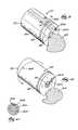
- FIG. 1shows an injector nozzle assembly 10 for conveying a flowable material into bone.
- the assembly 10is capable of carrying diverse types of flowable materials, e.g., bone cement or a suspension of one or more therapeutic substances, or both at the same time.
- the assembly 10can likewise be used for diverse therapeutic purposes, as well, e.g., to treat a diseased bone, or to prevent or treat fracture or collapse of a bone, or both at the same time.
- the illustrated embodimentshows the injector nozzle assembly 10 as part of a system 11 , which injects cement for treating bone fracture or collapse, which is a purpose for which the assembly 10 is particularly well adapted. It should be appreciated, however, that the nozzle assembly 10 is not limited to use in the treatment of bone fractures or collapse.
- FIG. 1shows the system 11 to include a tool 12 that forms a cement-receiving cavity in cancellous bone and a tool 14 , to which the assembly 10 is releasably attached to convey cement into the formed cancellous bone cavity.
- the first tool 12includes a catheter tube 16 having a distal end 18 , which carries an expandable body 20 .
- FIG. 1shows the body 20 in a collapsed geometry, which permits the physician to insert the body 20 into the interior volume of a targeted bone. Once inserted into bone, the physician can convey fluid to expand the body 20 , as shown in phantom lines in FIG. 1 .
- expansion of the body 20creates a cavity in cancellous bone.
- the use of expandable bodies to treat bones in this fashionis disclosed in U.S. Pat. Nos. 4,969,888 and 5,108,404, which are incorporated herein by reference.
- the nozzle assembly 10is deployed into the formed cavity to dispense bone cement, as will also be described in greater detail later.
- the cementcures and hardens to provide renewed interior structural support for cortical bone surrounding the cancellous bone.
- the injection nozzle assembly 10is intended to be component that can be removably connected to a conventional injection tool 14 , e.g., by a threaded connector 36 (see FIG. 2 ).
- the tool 14comprises a pistol-shaped grip, which will be referred to as a gun 22 .
- the gun 22includes an end fitment 24 , to which a cartridge 26 is removably attached, for example, by threaded screw engagement (not shown).
- the cartridge 26includes an interior, movable piston 28 .
- the nozzle assembly 10comprises an injection tube 30 .
- the injection tubeis releasably coupled to the front end of the cartridge 26 by the threaded connector 36 , which mates with a screw connector 37 on the cartridge.
- the injection tube 30includes a center lumen 32 .
- the nozzle assembly 10also includes a distal dispensing end 34 , through which the center lumen 32 extends.
- the cartridge 26contains bone cement 38 .
- the cartridge 26can be loaded with bone cement 38 in various way.
- bone cement 38is typically mixed in an external mixing device (not shown) from two components. Upon mixing, the two components begin to cure from a low viscosity, relatively free flowing liquid, like a thin pancake batter, to a substantially less flowable, putty like character. Eventually the cement 38 hardens to a rigid state within the targeted bone cavity formed by the expandable body 20 .
- a ram rod 40extends within the gun 22 .
- the rod 40carries a ram disk 44 .
- the rod 40is coupled to a finger trigger 42 .
- the rod 40advances the ram disk 44 into contact with the cartridge piston 28 . Advancement of the cartridge piston 28 , in turn, pushes the bone cement 38 through the screw connector 37 into the lumen 32 of the injection tube 30 and out through the dispensing end 34 , as FIG. 1 shows.
- the gun 22can be conventional and are not essential to the invention.
- the gun 22can comprise a cement gun made, for example, by Stryker Corporation (Kalamazoo, Mich.). This particular gun has a manually operated trigger with a mechanical advantage of about 9 to 1. Other injection guns may be used, having more or less mechanical advantage. Non-manually operated injection guns can also be used.
- the nozzle assembly 10can be constructed in various ways.
- the injector tube 30including its dispensing end 34 , can be made of a plastic material, such as polyethylene or other suitable polymer.
- the diameter and length of the nozzle assembly 10will vary according to the nature of the procedure.
- the nozzle assembly 10can be about 10 to 30 cm long with an outer diameter of about 4 to 12 mm.
- the nozzle assembly 10can be about 18 to 30 cm long with an outer diameter of about 3 to 8 mm in diameter.
- the dispensing end 34 of the nozzle assembly 10is either deflected or is otherwise capable of being deflected outside the main axis 46 of the tube 30 .
- the deflectiondefines a radius of curvature, which aids in the deployment of the dispensing end 34 within the targeted region.
- the deflection of the distal tube end 36can be accomplished in various ways, which the following description exemplifies.
- the dispensing end 34is normally biased into a prescribed deflected condition.
- the biascan be thermally set, using, for example, polyurethane or nylon material for the tube.
- the dispensing end 34can carry a length of prebent memory wire material 48 , made from, e.g., a nickel-titanium alloy, which biases the dispensing end 34 toward the desired deflected geometry.
- the angle of the deflectioncan vary, according to the geometry at the intended treatment site.
- the biasis overcome by passage of the dispensing end 34 through a guide sheath, which temporarily straightens the dispensing end 34 during its deployment in the intended treatment site. When free of the confines of the guide sheath, the bias returns the dispensing end 34 to its preestablished deflected condition.
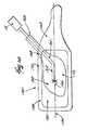
- the injection tube 30carries steering wires 50 and 52 .
- the steering wires 50 and 52extend through side lumens, respectively 50 A and 52 A in the tube 30 and are coupled to the dispensing end 34 .
- steering wires 50 and 52are shown for the purpose of illustration, but it should be realized that more or fewer steering wires may be used.
- the steering wires 50 and 52are coupled to a steering mechanism 54 located on the proximal end of the tube 30 near the gun cartridge 26 , for manipulation by the physician.
- the steering mechanism 54comprises a rotatable wheel 56 with a control lever 55 , to which the steering wires 50 and 52 are coupled.
- Other types of steering mechanisms 54such as pull tabs or linear actuators, can be used.
- position of the control lever 55corresponds with the angular orientation of the dispensing end 34 .
- the control lever 55is located in the center position C, the dispensing end 34 is in a straightened condition C′.
- the control lever 55is moved down or clockwise (for example, to phantom line position D) the dispensing end 34 is likewise moved to phantom line position D′, and the rotation angle A 1 between position C and D generally corresponds with the deflection angle A 1 ′ between position C′ and D′.
- one embodiment of the nozzle assembly 10includes a length of wire 100 carried by the dispensing end 34 .
- the wire 100extends across the central opening 32 , forming a loop 102 for cutting loose the cement bolus 62 expelled through the lumen 32 .
- rotation of the injection tube 30rotates the dispensing end 34 and, with it, the loop 102 .
- the loop 102rotates within the expelled bolus 62 of cement adjacent the terminal end of the lumen 32 .
- Rotation of the loop 102 through 180°cuts loose the expelled cement bolus 62 from the unexpelled cement mass 64 , which resides within the dispensing end 34 .
- the loop 102integrally carried by the dispensing end 34 , creates a consistent and clean break between the expelled bolus 62 and the unexpelled mass 64 .
- the nozzle assembly 10includes two lengths of wire 126 and 128 carried by the dispensing end 34 .
- the wires 126 and 128cross over the center lumen 32 , forming two cement cutting loops 130 and 132 in the path of cement expelled by the lumen 32 .
- Rotation of the dispensing end 34 through 90°passes the two loops 64 and 66 through the cement bolus 62 , severing the cement bolus 62 from the cement mass residing in the dispensing end 34 , in the manner shown in FIG. 5 .
- the dispensing end 34 of the injection tube 30 shown in FIGS. 4 to 6can, if desired, be preformed with a normal deflection, as previously described, to offset the dispensing end 34 with respect to the axis 46 of the injection tube 30 .
- the tube 30can also carry steering wires 50 and 52 , as shown in FIG. 3, to steer the dispensing end 34 .
- the steering and cement cutting elementscan be combined.
- the nozzle assembly 10includes a length of wire 134 , which is threaded through side lumens 136 A and 136 B, which extend through the tube 30 (in the manner shown in FIG. 3 ).
- the wire 134forms an exterior loop 58 at the tip of the dispensing end 34 .
- the side lumens 136 A and 136 Bare generally diametrically spaced with respect to the center lumen 32 , so that the exterior loop 58 extends across the center lumen 32 , generally bisecting it.
- the exterior loop 58serves as a cement cutting tool, as previously described.
- the wire 134is fixed to the tip of the dispensing end 34 , so that pulling on either leg of the wire 134 will bend the dispensing end 134 .
- the legs of the threaded wire 134thereby serve as the first and second steering wires 50 and 52 , which deflect the dispensing end 34 in the manner previously described and shown in FIG. 3 .
- FIG. 8shows another alternative embodiment, in which two lengths of wires 138 and 140 are threaded through multiple pairs of side lumens 142 A, 142 B, 144 A, and 144 B, which extend through the tube 30 .
- the wires 138 and 140forming circumferentially spaced, multiple steering wires 50 , 51 , 52 , and 53 .
- the wires 138 and 140also cross over the center lumen 32 , forming two loops 64 and 66 across the dispensing end 34 .
- the wires 138 and 140are fixed by adhesive or other suitable manner to the tip of the dispensing end, forming multiple steering wire legs 50 , 51 , 52 , 53 .
- the fixed legs 50 , 51 , 52 , and 53provide multi-planar steering.
- the two loops 64 and 66also serve as cement cutters.
- FIGS. 9 to 11show an alternative embodiment of a nozzle assembly 10 , which includes a bent stylet 200 to cut loose an expelled cement bolus 62 .
- the stylet 200is slidably carried by an interior lumen 202 in the injection tube 30 .
- a locating tab 206 on the stylet 200mates with a groove or keyway 208 in the lumen 202 , to prevent rotation of the stylet 200 in the lumen 202 .
- a suitable push-pull mechanism(not shown) is accessible at the proximal end of the injection tube 30 to affect advancement and retraction of the stylet 200 in the lumen 202 .
- the distal end 204 of the stylet 200is preformed with an angle bend.
- the distal end 204When located in the lumen 202 (as FIG. 9 shows), the distal end 204 is retained in a straightened condition.
- the distal end 204assumes the preformed, bent configuration.
- the locating tab 206 and mating keyway 208orient the stylet 200 , so that, when moved free of the lumen 202 , the distal end 204 bends toward and over the central opening 32 of the tube 32 , as FIG. 10 shows.
- the distal end 204preferably extends at least half way or more across the central opening 32 of the tube 30 .
- the cement bolus 62is expressed from the central opening 32 of the dispensing end 34 (as FIG. 9 shows).
- the physicianslides the distal stylet end 204 forward from the lumen 202 .
- the stylet end 204freed from the lumen 202 , bends over the central opening 32 into the cement bolus 62 .
- Rotation of the dispensing end 34 through 360°passes the distal stylet end 204 through the cement bolus 62 , severing the bolus 62 from the cement mass in the dispensing end 34 .
- FIGS. 12 and 13show another alternative embodiment of a nozzle assembly 10 which, upon rotation, cuts loose an expelled cement bolus 62 .
- the nozzle assembly 10includes an injection tube 30 like that shown in FIG. 2 .
- the tube 30includes a threaded connector 36 , which screws onto the connector 37 of the cement gun cartridge 26 .
- the tube 30includes a center lumen 32 to transport cement from the cartridge 26 to a distal dispensing end 34 .
- the center lumen 32does not extend axially through the tip of the distal dispensing end 34 .
- the tip of the dispensing end 34is closed and includes at least one dispensing port 180 extending at an angle from the central lumen 32 .
- the port 180opens on a side of the dispensing end 34 .
- the cement bolus 62is expressed through the side dispensing port 180 , and not through the distal tip of the dispensing end 34 .
- rotation of the dispensing end 34(indicated by arrow 182 ) moves the dispensing port 180 along an arc transversely of and away from the cement bolus 62 .
- the transverse movement of the side dispensing port 180 away from the bolus 32severs the bolus 32 from the cement mass residing in the center lumen 32 .
- the dispensing end 34 of the injection tube 30can, if desired, be preformed with a normal deflection, as previously described, to offset the dispensing end 34 with respect to the axis 46 of the injection tube 30 .
- the tube 30can also carry steering wires 50 and 52 , as shown in FIG. 3, to steer the dispensing end 34 .
- the threaded connector 36which releasably couples the injection tube 30 to the screw connector 37 on the front end of the cartridge 26 of the cement gun 22 , can include a fitting 104 that permits rotation of the injection tube 30 relative to the connector 36 and the gun 22 .
- the rotating fitting 104includes an adaptor 108 carried for rotation within the connector 36 .
- the proximal end 110 of the injector tube 30is secured to the adaptor 108 for common rotation.
- a retaining ring 112 outside the connector 36surrounds tube 30 , allowing its rotation but otherwise restraining rearward axial movement.
- An o-ring 114is contained between the adaptor 108 and the end wall of the connector 36 . The o-ring 114 restrains forward axial movement of the tube 30 , while also preventing leakage of cement.
- the rotating fitting 104permits the physician to rotate the injection tube 30 with one hand, and thereby rotate the nozzle 34 (as arrows 106 show in FIG. 14 ), while holding the gun 22 stationary in another hand.
- the injection tube 30can carry a hub or grip 115 to facilitate rotation.
- the rotating fitting 104simplifies handling and manipulation of the cement injection tool 14 during rotation of the injection tube 30 .
- the physicianis able to rotate the injection tube 30 , causing the one or more cement cutting loops carried by the rotating dispensing end 34 to cut loose an expelled cement bolus 62 (as shown in FIGS. 4 and 5, 9 and 10 , and 12 and 13 ), without rotating the gun 22 itself.
- rotation of the tube 30further helps locate the dispensing end 34 in the desired position, again without the need to rotate the gun 22 .
- the rotating fitting 104can include indicia to gauge orientation or rotation of the injection tube 30 .
- the indiciaincludes an index mark 210 scribed on the connector 36 , which aligns with an index mark 212 scribed on the proximal end of the injection tube 30 . Alignment of the marks 210 and 212 places the dispensing end 34 in a particular, preestablished orientation.
- alignment of the marks 210 and 212can designate that the deflection is to the right of the main axis 46 .
- the index mark 210can also include a visual or tactile identifier (for example, a raised letter “R” in FIG. 15) to further aid the physician in ascertaining the orientation.
- the fitting 104can also include additional auxiliary index marks (two of which 214 and 216 are shown in FIG. 15) and associated visual or tactile identifiers (respectively, “U” and “D”). Alignment of the mark 212 with auxiliary mark 214 indicates that the deflection orients the dispensing end 34 upward. Likewise, alignment of the mark 212 with auxiliary mark 216 indicates that the deflection orients the dispensing end 34 downward.
- Another auxiliary mark and associated identifier(not shown), located diametrically opposite to the mark 210 , can also indicate a left orientation of the deflected dispensing end 34 .
- the alignment of the index mark 212 with the index marks 210 , 214 , and 216allows the physician to remotely orient the deflected end 34 in a desired way, without reliance upon x-ray or other internal visualization technique. Tracking the rotation of the index mark 212 relative to one or more of the index marks 210 , 214 , or 216 also allows the physician to gauge the rotation of the injection tube 30 , to achieve the degree of rotation necessary to cut the cement bolus 62 loose.
- alignment of the marks 210 and 212can designate that the steering wires 50 and 52 extend in a particular vertical or horizontal plane. With this orientation known, the physician can operate the steering mechanism 56 to achieve the desired bending action, without reliance upon x-ray or other form of internal visualization. Relative movement of the index marks also allows the physician to monitor the extent of rotation of the injection tube 30 when cutting the cement bolus 62 loose.
- alignment of the marks 210 and 212can designate the orientation of the dispensing port 180 , either left, right, up, or down. Relative movement of the index marks also allows the physician to monitor the extent of rotation of the injection tube 30 when cutting the cement bolus 62 loose.
- the nozzle assembly 10includes one or more radiological markers 68 .
- the markers 68are made from known radiopaque materials, like platinum, gold, calcium, tantalum, and other heavy metals. At least one marker 68 is placed at or near the dispensing end 34 , to allow radiologic visualization of the dispensing end 34 within the targeted bone area.
- markerscan be used to allow the physician to visualize the location of the dispensing end 34 within the targeted treatment area.
- FIG. 16shows in coronal (top) view. It should be appreciated, however, the nozzle assembly 10 is not limited in its application to vertebrae. The system 10 can be deployed equally as well in long bones and other bone types.
- the vertebra 150includes a vertebral body 152 , which extends on the anterior (i.e., front or chest) side of the vertebra 150 .
- the vertebral body 152includes an exterior formed from compact cortical bone 158 .
- the cortical bone 158encloses an interior volume of reticulated cancellous, or spongy, bone 160 (also called medullary bone or trabecular bone).
- the vertebral body 152is in the shape of an oval disk, which is generally symmetric about an anterior-posterior axis 154 and a mid-lateral axis 156 .
- the axes 154 and 156intersect in the middle region or geometric center of the body 152 , which is designated MR in the drawings.
- access to the interior volume of the vertebral body 152can be achieved. e.g., by drilling an access portal 162 through a side of the vertebral body 152 , which is called a postero-lateral approach.
- the portal 162 for the postero-lateral approachenters at a posterior side of the body 152 and extends at angle forwardly toward the anterior of the body 152 .
- the portal 162can be performed either with a closed, mininimally invasive procedure or with an open procedure.
- a guide sheath 166is located in the access portal 162 .
- the tool 12is introduced through the guide sheath 166 , with the expandable body 20 collapsed.
- the physicianconveys a pressurized fluid into the body 20 to expand it.
- the fluidis preferably radio-opaque to facilitate visualization.
- RenografinTM contract mediacan be used for this purpose.
- the body 20is preferably left inflated for an appropriate waiting period, for example, three to five minutes, to allow coagulation inside the vertebral body 152 .
- an appropriate waiting periodfor example, three to five minutes, to allow coagulation inside the vertebral body 152 .
- the physiciancollapses the body 20 and removes it.
- the formed cavity 164remains in the interior volume of the vertebral body 152 .
- the second tool 14is now readied for deployment.
- the physiciandirects the injection tube 30 through the guide sheath 166 into the formed cavity 164 .
- dispensing end 34If the dispensing end 34 is normally biased into a bent condition (as exemplified in FIG. 2 ), passage through the guide sheath 166 overcomes the bias and straightens out the dispensing end 34 . Once free of the guide sheath 166 , the dispensing end 34 returns to its normally biased condition.
- the tube 30can include prepositioned markers 218 ( 0 ) to 218 ( 2 ) along its length.
- the markers 218 ( 0 ) to 218 ( 2 )are positioned to successively align with the proximal edge 220 of the guide sheath 166 at intervals that mark the extent to which the dispensing end 34 extends beyond the distal edge 222 of the guide sheath 166 .
- FIG. 19Ashows, when marker 218 ( 0 ) and the proximal edge 220 align, the distal edge 222 of the guide sheath 166 and the dispensing end 34 are coincident (i.e., the tip of the dispensing end 34 coterminous with the distal edge 222 of the sheath 166 ).
- FIG. 19Bshows, subsequent movement of the tube 30 in the sheath 166 brings the marker 218 (1) into alignment with the proximal edge 220 .
- This alignmentindicates that the tip of the dispensing end 34 projects beyond the distal edge 222 by a first, predetermined distance D 1 .
- FIG. 19Cshows, subsequent movement of the tube 30 to further advance the dispensing end 34 brings the marker 218 (2) into alignment with the proximal edge 220 .
- This alignmentindicates that the dispensing end 34 projects beyond the distal edge 222 by a second, predetermined distance D 2 .
- markers 218can vary.
- the markers 218allow the physician to gauge when and to what extent the dispensing end 34 projects into the targeted site, without need for direct visualization.
- the physicianmay rotate the injection tube 30 .
- Rotation of the injection tube 30orients the dispensing end 34 within the cavity 164 before or during the injection of cement 38 .
- the rotationmay be accomplished without rotating the gun 22 .
- the extent of rotation and the orientation of the dispensing end 34can be observed using the markers 212 / 210 , 214 , and 216 on the fitting 104 (see FIG. 15 ), without active internal visualization.
- the physicianmay selectively bend the dispensing end 34 under radiological visualization provided by the markers 68 . In this way, the physician can steer the dispensing end 34 into the desired position or positions within the cavity 164 before or during injection of cement 38 .
- the markers 212 / 210 , 214 , and 216 on the fitting 104aid the steering process (see FIG. 15 ), without active internal visualization.
- the postero-lateral access portal 162does not align the injection tube 30 with the geometric axes 154 and 156 of the vertebral body 152 . Nevertheless, deflection of the dispensing end 34 aligns the end 34 in the middle region MR of the body 152 along the mid-lateral axis 156 .
- the gun 22urges the cement 38 , or other filling material, into the cavity 164 .
- the physicianpreferably begins with the dispensing end 34 positioned in the lateral region opposite to the access portal 162 .
- the physicianprogressively moves the dispensing end 34 along the mid-lateral axis 156 through the middle region MR and toward the access portal 162 .
- the deflection of the dispensing end 34(by virtue of either the preformed bias or by active steering) allows the physician to maintain the desired alignment with the mid-lateral axis 156 .
- the deflection of the dispensing end 34also allows the physician to keep the dispensing end 34 continuously submerged in the filling material 38 , to thereby avoid the formation of air or fluid pockets.
- the physicianobserves the progress of the injection radiologically using the markers 68 , positioning the dispensing end 34 by rotation or steering, or both, as just described.
- the physicianflows material 38 into the cavity 164 , until the material 38 reaches the interior end of the guide sheath 166 .
- the dispensing end 34carries one or more exterior loops (as exemplified in FIGS. 4 to 10 ), or a side dispensing port 180 (as exemplified in FIGS. 12 and 13 )
- rotation of the dispensing end 34will cleanly sever the injected cement bolus residing in the cavity 164 from the unexpelled cement residing within the dispensing end 34 (as FIGS. 4 and 5 and FIGS. 12 and 13 show).
- cement residing in the cavity 164will not be inadvertently drawn out of the cavity 164 upon withdrawal of the dispensing end 34 .
- Rotation of the dispensing end 34 to sever the material bolusalso avoids the formation of sharp pedicles in the material bolus, which could irritate surrounding tissue.
- the markers 212 / 210 , 214 , and 216 on the fitting 104aid in monitoring the extent of rotation, without active internal visualization.
- FIG. 18shows in a lateral view
- access into the interior volume of a vertebral body 152can also be accomplished by drilling an access portal 168 through either pedicle 170 .
- Thisis called a transpedicular approach.
- the access portal 170 for a transpedicular approachenters at the top of the vertebral body 152 , where the pedicle 170 is relatively thin, and extends at an angle downward toward the bottom of the vertebral body 152 to enter the interior volume.
- the tool 12is deployed through a guide sheath 166 in the portal 168 to form a cavity 172 , in the same manner described above.
- the physiciancan manipulate the second tool 14 to steer the dispensing end 34 of the nozzle assembly 10 into the cavity 172 .
- the transpedicular access portalaligns the tube 30 obliquely with respect to the axes 154 and 156 , the deflected dispensing end 34 can be rotated into general alignment with either the anterior-posterior axis 154 or the mid-lateral axis 156 while injecting cement.
- the deflected dispensing end 34allows the introduction of cement 38 into the middle region MR of the vertebral body 152 , using either postero-lateral access or a transpedicular access.
- the cement 28when hardened, provides support uniformly across the middle region MR. The capability of the vertebral body 152 to withstand loads is thereby enhanced.
- the above described procedure, carried out in a minimally invasive manner,can also be carried out using an open surgical procedure.
- open surgerythe physician can approach the bone to be treated as if the procedure is percutaneous, except that there is no skin and other tissues between the surgeon and the bone being treated. This keeps the cortical bone as intact as possible, and can provide more freedom in accessing the interior volume of the vertebral body 152 .
- the cement 38undergoes a chemical reaction that generates heat.
- the cement temperatureis below a given threshold value, the cement 38 maintains a flowing, viscous liquid state, which is suited for introduction through the nozzle assembly 10 into the targeted region.
- the cement 38begins to harden, progressively losing its flow characteristic and becoming more resistant to passage through the nozzle assembly 10 . It is desirable to expel the loose cement bolus 62 before the threshold temperature is reached.
- FIG. 20shows a system 240 for cooling the nozzle assembly 10 during passage of the cement 38 through the dispensing end 34 .
- the system 240includes the injection tube 30 , which is releasably coupled to the front end of the cartridge 26 by the threaded connector 36 , as previously described.
- the tube 30includes the center lumen 32 , through which cement 38 conveyed from the cartridge 26 passes.
- the system 240further includes at least one paired set of side lumens, which extend through the tube 30 axially beside the center lumen 32 .
- four paired lumen setsare shown, designated 242 A and B, 244 A and B, 246 A and B, and 248 A and B.
- each lumen set 242 A/B; 244 A/B; 246 A/B; and 248 A/Bcomprises a closed loop for carrying a cooling fluid from a source 250 , through the tube 30 , and to waste 252 .
- the lumen designated A in each set 242 A/B; 244 A/B; 246 A/B; and 248 A/Bcommunicates at its proximal end with the cooling fluid source 250 via an in line pump 254 .
- the lumen designated A in each set 242 A/B; 244 A/B; 246 A/B; and 248 A/Btherefore comprises an inlet path for the cooling fluid.
- the inlet lumen A of each set 242 A/B; 244 A/B; 246 A/B; and 248 A/Bcommunicates at its distal end with the distal end of the lumen designated B in its respective set 242 A/B; 244 A/B; 246 A/B; or 248 A/B.
- communication between the distal ends of the lumens A and B in each set 242 A/B; 244 A/B; 246 A/B; and 248 A/Bis established by removing material between the lumens A and B to form a channel 256 between them, and laying a sealing material 258 over the channel 256 .
- the proximal ends of the lumens B in each set 242 A/B; 244 A/B; 246 A/B; and 248 A/Bcommunicate with waste 252 .
- the lumen B of each set 242 A/B; 244 A/B; 246 A/B; and 248 A/Bthereby comprises a return path for the cooling fluid.
- the cooling fluidis at a desired temperature, which is cooler than the threshold temperature of the cement 38 .
- the source fluidcan comprise tap water at a temperature of about 68° F. (20° C.).
- the pump 254conveys cooling fluid from the source 250 through the inlet paths 242 A, 244 A, 246 B, and 248 B.
- the return paths 242 B, 244 B, 246 B, and 248 Bcarry the cooling fluid to waste 252 .
- the circulation of cooling fluid in the tube 30 along the center lumen 32dissipates heat generated by the curing cement 38 , to mediate the temperature increase in the curing cement 38 .
- the circulation of cooling fluidthereby keeps the curing cement 38 in the center lumen 32 in a viscous flowing condition for a longer period of time.
- the return paths 242 B, 244 B, 246 B, and 248 Bconvey cooling fluid to waste 252 downstream of proximal end of the center lumen 30 . This quickens the discharge of heated return fluid from the tube 30 to thereby further minimize the temperature increase within the center lumen 32 .
- system 250can also include a cutting element to sever the cement flow in response to rotation of the tube 30 , as well as means for deflecting the dispensing end 34 , in any of the manners previously described.
Landscapes
- Health & Medical Sciences (AREA)
- Life Sciences & Earth Sciences (AREA)
- Orthopedic Medicine & Surgery (AREA)
- Surgery (AREA)
- Animal Behavior & Ethology (AREA)
- General Health & Medical Sciences (AREA)
- Biomedical Technology (AREA)
- Heart & Thoracic Surgery (AREA)
- Medical Informatics (AREA)
- Molecular Biology (AREA)
- Nuclear Medicine, Radiotherapy & Molecular Imaging (AREA)
- Engineering & Computer Science (AREA)
- Public Health (AREA)
- Veterinary Medicine (AREA)
- Physics & Mathematics (AREA)
- Fluid Mechanics (AREA)
- Prostheses (AREA)
- Surgical Instruments (AREA)
- Coating Apparatus (AREA)
- Materials For Medical Uses (AREA)
Abstract
Description
Claims (5)
Priority Applications (1)
| Application Number | Priority Date | Filing Date | Title |
|---|---|---|---|
| US10/016,339US6814736B2 (en) | 1997-08-13 | 2001-12-10 | Methods for injecting flowable materials into bones |
Applications Claiming Priority (3)
| Application Number | Priority Date | Filing Date | Title |
|---|---|---|---|
| US08/910,809US6048346A (en) | 1997-08-13 | 1997-08-13 | Systems and methods for injecting flowable materials into bones |
| US09/496,987US6719761B1 (en) | 1997-08-13 | 2000-02-02 | System and methods for injecting flowable materials into bones |
| US10/016,339US6814736B2 (en) | 1997-08-13 | 2001-12-10 | Methods for injecting flowable materials into bones |
Related Parent Applications (1)
| Application Number | Title | Priority Date | Filing Date |
|---|---|---|---|
| US09/496,987DivisionUS6719761B1 (en) | 1997-08-13 | 2000-02-02 | System and methods for injecting flowable materials into bones |
Publications (2)
| Publication Number | Publication Date |
|---|---|
| US20020082605A1 US20020082605A1 (en) | 2002-06-27 |
| US6814736B2true US6814736B2 (en) | 2004-11-09 |
Family
ID=25429357
Family Applications (3)
| Application Number | Title | Priority Date | Filing Date |
|---|---|---|---|
| US08/910,809Expired - LifetimeUS6048346A (en) | 1997-08-13 | 1997-08-13 | Systems and methods for injecting flowable materials into bones |
| US09/496,987Expired - LifetimeUS6719761B1 (en) | 1997-08-13 | 2000-02-02 | System and methods for injecting flowable materials into bones |
| US10/016,339Expired - Fee RelatedUS6814736B2 (en) | 1997-08-13 | 2001-12-10 | Methods for injecting flowable materials into bones |
Family Applications Before (2)
| Application Number | Title | Priority Date | Filing Date |
|---|---|---|---|
| US08/910,809Expired - LifetimeUS6048346A (en) | 1997-08-13 | 1997-08-13 | Systems and methods for injecting flowable materials into bones |
| US09/496,987Expired - LifetimeUS6719761B1 (en) | 1997-08-13 | 2000-02-02 | System and methods for injecting flowable materials into bones |
Country Status (7)
| Country | Link |
|---|---|
| US (3) | US6048346A (en) |
| EP (1) | EP1003433A1 (en) |
| JP (1) | JP2001514922A (en) |
| CN (1) | CN1276711A (en) |
| AU (1) | AU7711198A (en) |
| CA (1) | CA2296695A1 (en) |
| WO (1) | WO1999008616A1 (en) |
Cited By (119)
| Publication number | Priority date | Publication date | Assignee | Title |
|---|---|---|---|---|
| US20040247849A1 (en)* | 2003-06-05 | 2004-12-09 | Csaba Truckai | Polymer composites for biomedical applications and methods of making |
| US20050031578A1 (en)* | 2002-03-22 | 2005-02-10 | Doctor's Research Group, Inc. | Methods of performing medical procedures which promote bone growth, compositions which promote bone growth, and methods of making such compositions |
| US20050182414A1 (en)* | 2004-01-08 | 2005-08-18 | Richard Manzi | Apparatus and method for injecting fluent material at a distracted tissue site |
| US20050220771A1 (en)* | 2002-03-22 | 2005-10-06 | Doctor's Research Group, Inc. | Methods of performing medical procedures that promote bone growth, methods of making compositions that promote bone growth, and apparatus for use in such methods |
| US20050228397A1 (en)* | 1998-08-14 | 2005-10-13 | Malandain Hugues F | Cavity filling device |
| US20060009779A1 (en)* | 2004-06-29 | 2006-01-12 | Keith Collins | Devices for injecting a curable biomaterial into a intervertebral space |
| US20060085081A1 (en)* | 2004-06-07 | 2006-04-20 | Shadduck John H | Implants and methods for treating bone |
| US20060085009A1 (en)* | 2004-08-09 | 2006-04-20 | Csaba Truckai | Implants and methods for treating bone |
| US20060089715A1 (en)* | 2004-06-07 | 2006-04-27 | Csaba Truckai | Implants and methods for treating bone |
| US20060122621A1 (en)* | 2004-12-06 | 2006-06-08 | Csaba Truckai | Bone treatment systems and methods |
| US20060184192A1 (en)* | 2005-02-11 | 2006-08-17 | Markworth Aaron D | Systems and methods for providing cavities in interior body regions |
| US20060229628A1 (en)* | 2004-10-02 | 2006-10-12 | Csaba Truckai | Biomedical treatment systems and methods |
| US20060264965A1 (en)* | 2004-11-05 | 2006-11-23 | Shadduck John H | Bone treatment systems and methods |
| US20060293561A1 (en)* | 2005-06-24 | 2006-12-28 | Abay Eustaquio O Ii | System and methods for intervertebral disc surgery |
| US20070010844A1 (en)* | 2005-07-08 | 2007-01-11 | Gorman Gong | Radiopaque expandable body and methods |
| US20070010824A1 (en)* | 2005-07-11 | 2007-01-11 | Hugues Malandain | Products, systems and methods for delivering material to bone and other internal body parts |
| US20070010848A1 (en)* | 2005-07-11 | 2007-01-11 | Andrea Leung | Systems and methods for providing cavities in interior body regions |
| US20070006692A1 (en)* | 2005-07-11 | 2007-01-11 | Phan Christopher U | Torque limiting device |
| US20070010845A1 (en)* | 2005-07-08 | 2007-01-11 | Gorman Gong | Directionally controlled expandable device and methods for use |
| US20070055276A1 (en)* | 2005-07-11 | 2007-03-08 | Edidin Avram A | Systems and methods for inserting biocompatible filler materials in interior body regions |
| US20070055201A1 (en)* | 2005-07-11 | 2007-03-08 | Seto Christine L | Systems and methods for providing cavities in interior body regions |
| US20070156242A1 (en)* | 2003-09-02 | 2007-07-05 | Lin Kwan K | Devices and methods for the treatment of bone fracture |
| US20070233249A1 (en)* | 2006-02-07 | 2007-10-04 | Shadduck John H | Methods for treating bone |
| US20070233258A1 (en)* | 2006-02-28 | 2007-10-04 | Zimmer Spine, Inc. | Vertebroplasty- device and method |
| US20070260257A1 (en)* | 2005-07-11 | 2007-11-08 | Phan Christopher U | Surgical device having interchangeable components and methods of use |
| US20080009877A1 (en)* | 2006-07-07 | 2008-01-10 | Meera Sankaran | Medical device with expansion mechanism |
| US20080027456A1 (en)* | 2006-07-19 | 2008-01-31 | Csaba Truckai | Bone treatment systems and methods |
| US20080071281A1 (en)* | 2006-09-08 | 2008-03-20 | Spine Wave Inc. | Modular Injection Needle and Seal Assembly |
| US20080086142A1 (en)* | 2006-10-06 | 2008-04-10 | Kohm Andrew C | Products and Methods for Delivery of Material to Bone and Other Internal Body Parts |
| US20080132899A1 (en)* | 2004-05-17 | 2008-06-05 | Shadduck John H | Composite implant and method for treating bone abnormalities |
| US20080243249A1 (en)* | 2007-03-30 | 2008-10-02 | Kohm Andrew C | Devices for multipoint emplacement in a body part and methods of use of such devices |
| US20090036799A1 (en)* | 2007-03-30 | 2009-02-05 | Medtronic Spinal And Biologics Business | Methods and Systems For The Diagnosis and Treatment of Medical Conditions in the Spine and Other Body Parts |
| US7559932B2 (en) | 2004-12-06 | 2009-07-14 | Dfine, Inc. | Bone treatment systems and methods |
| US7575577B2 (en) | 2001-11-01 | 2009-08-18 | Spinewave | Devices and methods for the restoration of a spinal disc |
| US7666227B2 (en) | 2005-08-16 | 2010-02-23 | Benvenue Medical, Inc. | Devices for limiting the movement of material introduced between layers of spinal tissue |
| US7678116B2 (en) | 2004-12-06 | 2010-03-16 | Dfine, Inc. | Bone treatment systems and methods |
| US20100087827A1 (en)* | 2007-03-30 | 2010-04-08 | Gamal Baroud | Method and apparatus for monitoring and/or controlling the curing of cements used in medical procedures |
| US7722620B2 (en) | 2004-12-06 | 2010-05-25 | Dfine, Inc. | Bone treatment systems and methods |
| US20100160921A1 (en)* | 2008-12-19 | 2010-06-24 | Arthrocare Corporation | Cancellous bone displacement system and methods of use |
| US20100174320A1 (en)* | 2007-07-20 | 2010-07-08 | Dfine, Inc. | Bone anchor apparatus and method |
| US20100191297A1 (en)* | 2009-01-23 | 2010-07-29 | Spartek Medical, Inc. | Systems and methods for injecting bone filler into the spine |
| US20100249793A1 (en)* | 2008-02-01 | 2010-09-30 | Dfine, Inc. | Bone treatment systems and methods |
| US7811291B2 (en) | 2007-11-16 | 2010-10-12 | Osseon Therapeutics, Inc. | Closed vertebroplasty bone cement injection system |
| US8066712B2 (en) | 2005-09-01 | 2011-11-29 | Dfine, Inc. | Systems for delivering bone fill material |
| US8070753B2 (en) | 2004-12-06 | 2011-12-06 | Dfine, Inc. | Bone treatment systems and methods |
| US8105236B2 (en) | 2005-07-11 | 2012-01-31 | Kyphon Sarl | Surgical access device, system, and methods of use |
| US8109933B2 (en) | 2007-04-03 | 2012-02-07 | Dfine, Inc. | Bone treatment systems and methods |
| US8128632B2 (en) | 2006-05-22 | 2012-03-06 | Orthovita, Inc. | Delivery of multicomponent compositions |
| US8163031B2 (en) | 2004-06-09 | 2012-04-24 | Dfine, Inc. | Composites and methods for treating bone |
| US8241335B2 (en) | 2004-11-10 | 2012-08-14 | Dfine, Inc. | Bone treatment systems and methods for introducing an abrading structure to abrade bone |
| US8366773B2 (en) | 2005-08-16 | 2013-02-05 | Benvenue Medical, Inc. | Apparatus and method for treating bone |
| US8430887B2 (en) | 2007-04-30 | 2013-04-30 | Dfine, Inc. | Bone treatment systems and methods |
| US8454617B2 (en) | 2005-08-16 | 2013-06-04 | Benvenue Medical, Inc. | Devices for treating the spine |
| US8487021B2 (en) | 2008-02-01 | 2013-07-16 | Dfine, Inc. | Bone treatment systems and methods |
| US8535327B2 (en) | 2009-03-17 | 2013-09-17 | Benvenue Medical, Inc. | Delivery apparatus for use with implantable medical devices |
| US8591583B2 (en) | 2005-08-16 | 2013-11-26 | Benvenue Medical, Inc. | Devices for treating the spine |
| US8696679B2 (en) | 2006-12-08 | 2014-04-15 | Dfine, Inc. | Bone treatment systems and methods |
| US8801800B2 (en) | 2009-11-20 | 2014-08-12 | Zimmer Knee Creations, Inc. | Bone-derived implantable devices and tool for subchondral treatment of joint pain |
| US8814873B2 (en) | 2011-06-24 | 2014-08-26 | Benvenue Medical, Inc. | Devices and methods for treating bone tissue |
| US8821504B2 (en) | 2009-11-20 | 2014-09-02 | Zimmer Knee Creations, Inc. | Method for treating joint pain and associated instruments |
| US8827981B2 (en) | 2007-11-16 | 2014-09-09 | Osseon Llc | Steerable vertebroplasty system with cavity creation element |
| US8864768B2 (en) | 2009-11-20 | 2014-10-21 | Zimmer Knee Creations, Inc. | Coordinate mapping system for joint treatment |
| US8906032B2 (en) | 2009-11-20 | 2014-12-09 | Zimmer Knee Creations, Inc. | Instruments for a variable angle approach to a joint |
| US8932295B1 (en) | 2011-06-01 | 2015-01-13 | Surgical Device Exchange, LLC | Bone graft delivery system and method for using same |
| US8945137B1 (en) | 2013-03-15 | 2015-02-03 | Surgical Device Exchange, LLC | Bone graft delivery system and method for using same |
| US9033987B2 (en) | 2009-11-20 | 2015-05-19 | Zimmer Knee Creations, Inc. | Navigation and positioning instruments for joint repair |
| US9060787B2 (en) | 2007-02-22 | 2015-06-23 | Spinal Elements, Inc. | Method of using a vertebral facet joint drill |
| US9119639B2 (en) | 2011-08-09 | 2015-09-01 | DePuy Synthes Products, Inc. | Articulated cavity creator |
| US9220554B2 (en) | 2010-02-18 | 2015-12-29 | Globus Medical, Inc. | Methods and apparatus for treating vertebral fractures |
| US9259257B2 (en) | 2009-11-20 | 2016-02-16 | Zimmer Knee Creations, Inc. | Instruments for targeting a joint defect |
| US9271835B2 (en) | 2009-11-20 | 2016-03-01 | Zimmer Knee Creations, Inc. | Implantable devices for subchondral treatment of joint pain |
| US9439693B2 (en) | 2013-02-01 | 2016-09-13 | DePuy Synthes Products, Inc. | Steerable needle assembly for use in vertebral body augmentation |
| US9445854B2 (en) | 2008-02-01 | 2016-09-20 | Dfine, Inc. | Bone treatment systems and methods |
| US9510885B2 (en) | 2007-11-16 | 2016-12-06 | Osseon Llc | Steerable and curvable cavity creation system |
| US9592317B2 (en) | 2005-08-22 | 2017-03-14 | Dfine, Inc. | Medical system and method of use |
| US9668881B1 (en) | 2013-03-15 | 2017-06-06 | Surgentec, Llc | Bone graft delivery system and method for using same |
| US9717544B2 (en) | 2009-11-20 | 2017-08-01 | Zimmer Knee Creations, Inc. | Subchondral treatment of joint pain |
| US9788963B2 (en) | 2003-02-14 | 2017-10-17 | DePuy Synthes Products, Inc. | In-situ formed intervertebral fusion device and method |
| US9901657B2 (en) | 2008-10-13 | 2018-02-27 | Dfine, Inc. | System for use in bone cement preparation and delivery |
| US10039584B2 (en) | 2008-04-21 | 2018-08-07 | Dfine, Inc. | System for use in bone cement preparation and delivery |
| US10085783B2 (en) | 2013-03-14 | 2018-10-02 | Izi Medical Products, Llc | Devices and methods for treating bone tissue |
| US10136934B2 (en) | 2005-08-22 | 2018-11-27 | Dfine, Inc. | Bone treatment systems and methods |
| US10231846B2 (en) | 2016-08-19 | 2019-03-19 | Stryker European Holdings I, Llc | Bone graft delivery loading assembly |
| US10238507B2 (en) | 2015-01-12 | 2019-03-26 | Surgentec, Llc | Bone graft delivery system and method for using same |
| US10463380B2 (en) | 2016-12-09 | 2019-11-05 | Dfine, Inc. | Medical devices for treating hard tissues and related methods |
| US10478241B2 (en) | 2016-10-27 | 2019-11-19 | Merit Medical Systems, Inc. | Articulating osteotome with cement delivery channel |
| US10624652B2 (en) | 2010-04-29 | 2020-04-21 | Dfine, Inc. | System for use in treatment of vertebral fractures |
| US10660656B2 (en) | 2017-01-06 | 2020-05-26 | Dfine, Inc. | Osteotome with a distal portion for simultaneous advancement and articulation |
| US10687828B2 (en) | 2018-04-13 | 2020-06-23 | Surgentec, Llc | Bone graft delivery system and method for using same |
| US10888433B2 (en) | 2016-12-14 | 2021-01-12 | DePuy Synthes Products, Inc. | Intervertebral implant inserter and related methods |
| US10940016B2 (en) | 2017-07-05 | 2021-03-09 | Medos International Sarl | Expandable intervertebral fusion cage |
| US10966840B2 (en) | 2010-06-24 | 2021-04-06 | DePuy Synthes Products, Inc. | Enhanced cage insertion assembly |
| US10973652B2 (en) | 2007-06-26 | 2021-04-13 | DePuy Synthes Products, Inc. | Highly lordosed fusion cage |
| US11026744B2 (en) | 2016-11-28 | 2021-06-08 | Dfine, Inc. | Tumor ablation devices and related methods |
| US11116647B2 (en) | 2018-04-13 | 2021-09-14 | Surgentec, Llc | Bone graft delivery system and method for using same |
| US11197681B2 (en) | 2009-05-20 | 2021-12-14 | Merit Medical Systems, Inc. | Steerable curvable vertebroplasty drill |
| US11273050B2 (en) | 2006-12-07 | 2022-03-15 | DePuy Synthes Products, Inc. | Intervertebral implant |
| US11344424B2 (en) | 2017-06-14 | 2022-05-31 | Medos International Sarl | Expandable intervertebral implant and related methods |
| US11426286B2 (en) | 2020-03-06 | 2022-08-30 | Eit Emerging Implant Technologies Gmbh | Expandable intervertebral implant |
| US11426290B2 (en) | 2015-03-06 | 2022-08-30 | DePuy Synthes Products, Inc. | Expandable intervertebral implant, system, kit and method |
| US11446155B2 (en) | 2017-05-08 | 2022-09-20 | Medos International Sarl | Expandable cage |
| US11446156B2 (en) | 2018-10-25 | 2022-09-20 | Medos International Sarl | Expandable intervertebral implant, inserter instrument, and related methods |
| US11452607B2 (en) | 2010-10-11 | 2022-09-27 | DePuy Synthes Products, Inc. | Expandable interspinous process spacer implant |
| US11497619B2 (en) | 2013-03-07 | 2022-11-15 | DePuy Synthes Products, Inc. | Intervertebral implant |
| US11510723B2 (en) | 2018-11-08 | 2022-11-29 | Dfine, Inc. | Tumor ablation device and related systems and methods |
| US11510788B2 (en) | 2016-06-28 | 2022-11-29 | Eit Emerging Implant Technologies Gmbh | Expandable, angularly adjustable intervertebral cages |
| US11596522B2 (en) | 2016-06-28 | 2023-03-07 | Eit Emerging Implant Technologies Gmbh | Expandable and angularly adjustable intervertebral cages with articulating joint |
| US11602438B2 (en) | 2008-04-05 | 2023-03-14 | DePuy Synthes Products, Inc. | Expandable intervertebral implant |
| US11607321B2 (en) | 2009-12-10 | 2023-03-21 | DePuy Synthes Products, Inc. | Bellows-like expandable interbody fusion cage |
| US11612491B2 (en) | 2009-03-30 | 2023-03-28 | DePuy Synthes Products, Inc. | Zero profile spinal fusion cage |
| US11654033B2 (en) | 2010-06-29 | 2023-05-23 | DePuy Synthes Products, Inc. | Distractible intervertebral implant |
| US11737881B2 (en) | 2008-01-17 | 2023-08-29 | DePuy Synthes Products, Inc. | Expandable intervertebral implant and associated method of manufacturing the same |
| US11752009B2 (en) | 2021-04-06 | 2023-09-12 | Medos International Sarl | Expandable intervertebral fusion cage |
| US11850160B2 (en) | 2021-03-26 | 2023-12-26 | Medos International Sarl | Expandable lordotic intervertebral fusion cage |
| US11911287B2 (en) | 2010-06-24 | 2024-02-27 | DePuy Synthes Products, Inc. | Lateral spondylolisthesis reduction cage |
| USRE49973E1 (en) | 2013-02-28 | 2024-05-21 | DePuy Synthes Products, Inc. | Expandable intervertebral implant, system, kit and method |
| US11986229B2 (en) | 2019-09-18 | 2024-05-21 | Merit Medical Systems, Inc. | Osteotome with inflatable portion and multiwire articulation |
| US12090064B2 (en) | 2022-03-01 | 2024-09-17 | Medos International Sarl | Stabilization members for expandable intervertebral implants, and related systems and methods |
| US12440346B2 (en) | 2023-03-31 | 2025-10-14 | DePuy Synthes Products, Inc. | Expandable intervertebral implant |
Families Citing this family (268)
| Publication number | Priority date | Publication date | Assignee | Title |
|---|---|---|---|---|
| ATE361028T1 (en)* | 1994-01-26 | 2007-05-15 | Kyphon Inc | IMPROVED INFLATABLE DEVICE FOR USE IN SURGICAL METHODS OF FIXATION OF BONE |
| US20060100635A1 (en)* | 1994-01-26 | 2006-05-11 | Kyphon, Inc. | Inflatable device for use in surgical protocol relating to fixation of bone |
| US6248110B1 (en)* | 1994-01-26 | 2001-06-19 | Kyphon, Inc. | Systems and methods for treating fractured or diseased bone using expandable bodies |
| US20030032963A1 (en)* | 2001-10-24 | 2003-02-13 | Kyphon Inc. | Devices and methods using an expandable body with internal restraint for compressing cancellous bone |
| US6241734B1 (en)* | 1998-08-14 | 2001-06-05 | Kyphon, Inc. | Systems and methods for placing materials into bone |
| US20030229372A1 (en)* | 1994-01-26 | 2003-12-11 | Kyphon Inc. | Inflatable device for use in surgical protocols relating to treatment of fractured or diseased bone |
| EP0873145A2 (en)* | 1996-11-15 | 1998-10-28 | Advanced Bio Surfaces, Inc. | Biomaterial system for in situ tissue repair |
| WO2004110300A2 (en)* | 2001-07-25 | 2004-12-23 | Disc Orthopaedic Technologies Inc. | Deformable tools and implants |
| IL128261A0 (en)* | 1999-01-27 | 1999-11-30 | Disc O Tech Medical Tech Ltd | Expandable element |
| US6048346A (en) | 1997-08-13 | 2000-04-11 | Kyphon Inc. | Systems and methods for injecting flowable materials into bones |
| US6440138B1 (en)* | 1998-04-06 | 2002-08-27 | Kyphon Inc. | Structures and methods for creating cavities in interior body regions |
| US6719773B1 (en) | 1998-06-01 | 2004-04-13 | Kyphon Inc. | Expandable structures for deployment in interior body regions |
| CA2333761C (en)* | 1998-06-01 | 2008-05-27 | Kyphon Inc. | Expandable preformed structures for deployment in interior body regions |
| US7621950B1 (en) | 1999-01-27 | 2009-11-24 | Kyphon Sarl | Expandable intervertebral spacer |
| US7052516B2 (en) | 1999-10-20 | 2006-05-30 | Anulex Technologies, Inc. | Spinal disc annulus reconstruction method and deformable spinal disc annulus stent |
| US8128698B2 (en) | 1999-10-20 | 2012-03-06 | Anulex Technologies, Inc. | Method and apparatus for the treatment of the intervertebral disc annulus |
| US6592625B2 (en) | 1999-10-20 | 2003-07-15 | Anulex Technologies, Inc. | Spinal disc annulus reconstruction method and spinal disc annulus stent |
| US7004970B2 (en) | 1999-10-20 | 2006-02-28 | Anulex Technologies, Inc. | Methods and devices for spinal disc annulus reconstruction and repair |
| US7615076B2 (en) | 1999-10-20 | 2009-11-10 | Anulex Technologies, Inc. | Method and apparatus for the treatment of the intervertebral disc annulus |
| US7951201B2 (en) | 1999-10-20 | 2011-05-31 | Anulex Technologies, Inc. | Method and apparatus for the treatment of the intervertebral disc annulus |
| US7935147B2 (en) | 1999-10-20 | 2011-05-03 | Anulex Technologies, Inc. | Method and apparatus for enhanced delivery of treatment device to the intervertebral disc annulus |
| US8632590B2 (en) | 1999-10-20 | 2014-01-21 | Anulex Technologies, Inc. | Apparatus and methods for the treatment of the intervertebral disc |
| AU5326701A (en)* | 2000-04-05 | 2001-10-23 | Kyphon Inc | Methods and devices for treating fractured and/or diseased bone |
| CN101543422B (en) | 2000-04-07 | 2012-07-04 | 科丰有限公司 | System for determining the expansion direction of an expandable structure within a bone |
| US7815649B2 (en)* | 2000-04-07 | 2010-10-19 | Kyphon SÀRL | Insertion devices and method of use |
| SE520688C2 (en)* | 2000-04-11 | 2003-08-12 | Bone Support Ab | An injectable bone mineral replacement material |
| US6506214B1 (en) | 2000-05-02 | 2003-01-14 | R. Michael Gross | Method and means for cementing a liner onto the face of the glenoid cavity of a scapula |
| DE10064202A1 (en)* | 2000-05-25 | 2001-11-29 | Pajunk Gmbh | Device for applying bone cement and cannula for such a device |
| US6749614B2 (en) | 2000-06-23 | 2004-06-15 | Vertelink Corporation | Formable orthopedic fixation system with cross linking |
| EP1292239B1 (en)* | 2000-06-23 | 2013-02-13 | University Of Southern California | Percutaneous vertebral fusion system |
| US6964667B2 (en)* | 2000-06-23 | 2005-11-15 | Sdgi Holdings, Inc. | Formed in place fixation system with thermal acceleration |
| US6899713B2 (en)* | 2000-06-23 | 2005-05-31 | Vertelink Corporation | Formable orthopedic fixation system |
| US6875212B2 (en)* | 2000-06-23 | 2005-04-05 | Vertelink Corporation | Curable media for implantable medical device |
| AU2001271440A1 (en) | 2000-06-27 | 2002-01-08 | Kyphon Inc. | Systems and methods for injecting flowable materials into bones |
| US7025771B2 (en)* | 2000-06-30 | 2006-04-11 | Spineology, Inc. | Tool to direct bone replacement material |
| SE517168C2 (en)* | 2000-07-17 | 2002-04-23 | Bone Support Ab | A composition for an injectable bone mineral replacement material |
| WO2002013700A2 (en)* | 2000-08-11 | 2002-02-21 | Sdgi Holdings, Inc. | Surgical instrumentation and method for treatment of the spine |
| AU2001281264B2 (en)* | 2000-08-14 | 2005-03-03 | Boston Scientific Limited | Steerable sphincterotome and methods for cannulation, papillotomy and sphincterotomy |
| US6679886B2 (en)* | 2000-09-01 | 2004-01-20 | Synthes (Usa) | Tools and methods for creating cavities in bone |
| EP1328220B1 (en)* | 2000-10-24 | 2011-01-05 | CryoLife, Inc. | Bioprosthetic filler and methods, particularly for the in situ formation of vertebral disc bioprosthetics |
| WO2002034148A2 (en)* | 2000-10-25 | 2002-05-02 | Kyphon Inc. | Systems and methods for reducing fractured bone using a fracture reduction cannula |
| US8083768B2 (en) | 2000-12-14 | 2011-12-27 | Ensure Medical, Inc. | Vascular plug having composite construction |
| US6846319B2 (en)* | 2000-12-14 | 2005-01-25 | Core Medical, Inc. | Devices for sealing openings through tissue and apparatus and methods for delivering them |
| US6623509B2 (en) | 2000-12-14 | 2003-09-23 | Core Medical, Inc. | Apparatus and methods for sealing vascular punctures |
| US6890343B2 (en)* | 2000-12-14 | 2005-05-10 | Ensure Medical, Inc. | Plug with detachable guidewire element and methods for use |
| US6896692B2 (en) | 2000-12-14 | 2005-05-24 | Ensure Medical, Inc. | Plug with collet and apparatus and method for delivering such plugs |
| CA2429149C (en)* | 2000-12-15 | 2010-08-24 | Spineology, Inc. | Annulus-reinforcing band |
| US7544196B2 (en)* | 2001-02-20 | 2009-06-09 | Orthovita, Inc. | System and kit for delivery of restorative materials |
| WO2002065926A1 (en)* | 2001-02-20 | 2002-08-29 | Vita Licensing Inc. | Biocompatible material |
| US6595998B2 (en)* | 2001-03-08 | 2003-07-22 | Spinewave, Inc. | Tissue distraction device |
| US20040083002A1 (en)* | 2001-04-06 | 2004-04-29 | Belef William Martin | Methods for treating spinal discs |
| WO2002083004A1 (en) | 2001-04-16 | 2002-10-24 | Kyphon Inc. | Insertion devices and method of use |
| US6632235B2 (en) | 2001-04-19 | 2003-10-14 | Synthes (U.S.A.) | Inflatable device and method for reducing fractures in bone and in treating the spine |
| US6616673B1 (en)* | 2001-04-19 | 2003-09-09 | Biomet, Inc. | Segmented joint distractor |
| US6746451B2 (en)* | 2001-06-01 | 2004-06-08 | Lance M. Middleton | Tissue cavitation device and method |
| US6599293B2 (en) | 2001-07-16 | 2003-07-29 | Stryker Instruments | Delivery device for bone cement |
| US6547432B2 (en)* | 2001-07-16 | 2003-04-15 | Stryker Instruments | Bone cement mixing and delivery device for injection and method thereof |
| US20030028251A1 (en) | 2001-07-30 | 2003-02-06 | Mathews Hallett H. | Methods and devices for interbody spinal stabilization |
| US6827718B2 (en)* | 2001-08-14 | 2004-12-07 | Scimed Life Systems, Inc. | Method of and apparatus for positioning and maintaining the position of endoscopic instruments |
| US6793660B2 (en)* | 2001-08-20 | 2004-09-21 | Synthes (U.S.A.) | Threaded syringe for delivery of a bone substitute material |
| US6736815B2 (en)* | 2001-09-06 | 2004-05-18 | Core Medical, Inc. | Apparatus and methods for treating spinal discs |
| US7004945B2 (en) | 2001-11-01 | 2006-02-28 | Spinewave, Inc. | Devices and methods for the restoration of a spinal disc |
| DE10154163A1 (en) | 2001-11-03 | 2003-05-22 | Advanced Med Tech | Device for straightening and stabilizing the spine |
| SE522098C2 (en)* | 2001-12-20 | 2004-01-13 | Bone Support Ab | Artificial bone mineral substitute material useful as an X-ray contrast medium comprises ceramic and water soluble non-ionic X-ray contrast agent |
| US6780191B2 (en)* | 2001-12-28 | 2004-08-24 | Yacmur Llc | Cannula system |
| US6582439B1 (en) | 2001-12-28 | 2003-06-24 | Yacmur Llc | Vertebroplasty system |
| US6733534B2 (en) | 2002-01-29 | 2004-05-11 | Sdgi Holdings, Inc. | System and method for spine spacing |
| US9782572B2 (en) | 2002-09-30 | 2017-10-10 | Nordson Corporation | Apparatus and methods for treating bone structures, tissues and ducts using a narrow gauge cannula system |
| US7488337B2 (en)* | 2002-09-30 | 2009-02-10 | Saab Mark A | Apparatus and methods for bone, tissue and duct dilatation |
| US8361067B2 (en) | 2002-09-30 | 2013-01-29 | Relievant Medsystems, Inc. | Methods of therapeutically heating a vertebral body to treat back pain |
| US7294132B2 (en)* | 2002-10-03 | 2007-11-13 | Wright Medical Technology, Inc. | Radially ported needle for delivering bone graft material and method of use |
| US20040122438A1 (en)* | 2002-12-23 | 2004-06-24 | Boston Scientific Corporation | Flex-tight interlocking connection tubing for delivery of bone cements/biomaterials for vertebroplasty |
| US7141054B2 (en)* | 2003-02-03 | 2006-11-28 | Biomet, Inc. | Method and apparatus for intramedullary delivery of a material |
| DE10309986B4 (en)* | 2003-02-28 | 2005-03-17 | Aesculap Ag & Co. Kg | Implant, implant system for rebuilding a vertebral body |
| SE0300620D0 (en)* | 2003-03-05 | 2003-03-05 | Bone Support Ab | A new bone substitute composition |
| ES2545328T3 (en) | 2003-03-14 | 2015-09-10 | Depuy Spine, Inc. | Bone cement hydraulic injection device in percutaneous vertebroplasty |
| US8066713B2 (en) | 2003-03-31 | 2011-11-29 | Depuy Spine, Inc. | Remotely-activated vertebroplasty injection device |
| US20050128867A1 (en)* | 2003-05-12 | 2005-06-16 | Henniges Bruce D. | Bone cement mixing and delivery system |
| US20040267272A1 (en)* | 2003-05-12 | 2004-12-30 | Henniges Bruce D | Bone cement mixing and delivery system |
| TW587932B (en)* | 2003-05-21 | 2004-05-21 | Guan-Gu Lin | Removable animal tissue filling device |
| TWI235055B (en)* | 2003-05-21 | 2005-07-01 | Guan-Gu Lin | Filling device capable of removing animal tissues |
| US7112205B2 (en)* | 2003-06-17 | 2006-09-26 | Boston Scientific Scimed, Inc. | Apparatus and methods for delivering compounds into vertebrae for vertebroplasty |
| US8415407B2 (en) | 2004-03-21 | 2013-04-09 | Depuy Spine, Inc. | Methods, materials, and apparatus for treating bone and other tissue |
| WO2004112661A1 (en)* | 2003-06-20 | 2004-12-29 | Myers Thomas H | Method and apparatus for strengthening the biomechanical properties of implants |
| IL156945A0 (en)* | 2003-07-15 | 2004-02-08 | Itzhak Tavori | Device and a method for orthopedic delivery of bone reconstruction medium |
| US6923813B2 (en) | 2003-09-03 | 2005-08-02 | Kyphon Inc. | Devices for creating voids in interior body regions and related methods |
| US8579908B2 (en) | 2003-09-26 | 2013-11-12 | DePuy Synthes Products, LLC. | Device for delivering viscous material |
| TW200511970A (en)* | 2003-09-29 | 2005-04-01 | Kwan-Ku Lin | A spine wrapping and filling apparatus |
| US8852229B2 (en)* | 2003-10-17 | 2014-10-07 | Cordis Corporation | Locator and closure device and method of use |
| US7361183B2 (en) | 2003-10-17 | 2008-04-22 | Ensure Medical, Inc. | Locator and delivery device and method of use |
| US20050124999A1 (en)* | 2003-10-31 | 2005-06-09 | Teitelbaum George P. | Device and method for radial delivery of a structural element |
| SE0302983D0 (en) | 2003-11-11 | 2003-11-11 | Bone Support Ab | Apparatus for providing spongy bone with bone replacement and / or bone strengthening material and associated method |
| US7524103B2 (en)* | 2003-11-18 | 2009-04-28 | Boston Scientific Scimed, Inc. | Apparatus for mixing and dispensing a multi-component bone cement |
| US7641664B2 (en)* | 2004-02-12 | 2010-01-05 | Warsaw Orthopedic, Inc. | Surgical instrumentation and method for treatment of a spinal structure |
| US20060135959A1 (en)* | 2004-03-22 | 2006-06-22 | Disc Dynamics, Inc. | Nuclectomy method and apparatus |
| US8029511B2 (en)* | 2004-03-22 | 2011-10-04 | Disc Dynamics, Inc. | Multi-stage biomaterial injection system for spinal implants |
| US20050245938A1 (en)* | 2004-04-28 | 2005-11-03 | Kochan Jeffrey P | Method and apparatus for minimally invasive repair of intervertebral discs and articular joints |
| US8142462B2 (en) | 2004-05-28 | 2012-03-27 | Cavitech, Llc | Instruments and methods for reducing and stabilizing bone fractures |
| US20050278023A1 (en) | 2004-06-10 | 2005-12-15 | Zwirkoski Paul A | Method and apparatus for filling a cavity |
| JP2008503275A (en)* | 2004-06-16 | 2008-02-07 | ウォーソー・オーソペディック・インコーポレーテッド | Surgical instruments and methods for treatment of spinal structures |
| SE527528C2 (en)* | 2004-06-22 | 2006-04-04 | Bone Support Ab | Apparatus for the preparation of curable pulp and use of the apparatus |
| CN101065080B (en) | 2004-07-30 | 2021-10-29 | 德普伊新特斯产品有限责任公司 | Materials and Instruments for Manipulating Bone and Other Tissues |
| US20080319445A9 (en)* | 2004-08-17 | 2008-12-25 | Scimed Life Systems, Inc. | Apparatus and methods for delivering compounds into vertebrae for vertebroplasty |
| US8038682B2 (en) | 2004-08-17 | 2011-10-18 | Boston Scientific Scimed, Inc. | Apparatus and methods for delivering compounds into vertebrae for vertebroplasty |
| JP2008511422A (en)* | 2004-09-02 | 2008-04-17 | クロストゥリーズ・メディカル・インコーポレーテッド | Device and method for distraction of spinal disc space |
| US7317331B2 (en)* | 2004-11-08 | 2008-01-08 | Tabula, Inc. | Reconfigurable IC that has sections running at different reconfiguration rates |
| US20060100706A1 (en)* | 2004-11-10 | 2006-05-11 | Shadduck John H | Stent systems and methods for spine treatment |
| US7799078B2 (en)* | 2004-11-12 | 2010-09-21 | Warsaw Orthopedic, Inc. | Implantable vertebral lift |
| US8562607B2 (en) | 2004-11-19 | 2013-10-22 | Dfine, Inc. | Bone treatment systems and methods |
| US20060122614A1 (en)* | 2004-12-06 | 2006-06-08 | Csaba Truckai | Bone treatment systems and methods |
| US20090264939A9 (en)* | 2004-12-16 | 2009-10-22 | Martz Erik O | Instrument set and method for performing spinal nuclectomy |
| AR055833A1 (en)* | 2005-01-07 | 2007-09-12 | Celonova Biosciences Inc | IMPLANTABLE THREE DIMENSIONAL BEAR SUPPORT |
| US20060265077A1 (en)* | 2005-02-23 | 2006-11-23 | Zwirkoski Paul A | Spinal repair |
| US20060216230A1 (en)* | 2005-03-28 | 2006-09-28 | The Regents Of The University Of California | Radioactive bone cement for treatment of tumors in bone |
| EP1868539A2 (en) | 2005-04-15 | 2007-12-26 | Musculoskeletal Transplant Foundation | Vertebral disc repair |
| US8083722B2 (en)* | 2005-04-29 | 2011-12-27 | Warsaw Orthopedic, Inc | Instrumentation for injection of therapeutic fluid into joints |
| FR2885032B1 (en)* | 2005-04-29 | 2007-07-27 | Sdgi Holdings Inc | KIT AND INSTRUMENTATION FOR EXECUTING A SPINAL IMPLANTATION PROCEDURE |
| US7850656B2 (en)* | 2005-04-29 | 2010-12-14 | Warsaw Orthopedic, Inc. | Devices and methods for delivering medical agents |
| US8506646B2 (en)* | 2005-04-29 | 2013-08-13 | Warsaw Orthopedic, Inc. | Multi-purpose medical implant devices |
| US8092464B2 (en)* | 2005-04-30 | 2012-01-10 | Warsaw Orthopedic, Inc. | Syringe devices and methods useful for delivering osteogenic material |
| US20060253198A1 (en)* | 2005-05-03 | 2006-11-09 | Disc Dynamics, Inc. | Multi-lumen mold for intervertebral prosthesis and method of using same |
| US20060253199A1 (en)* | 2005-05-03 | 2006-11-09 | Disc Dynamics, Inc. | Lordosis creating nucleus replacement method and apparatus |
| US20060265076A1 (en)* | 2005-05-03 | 2006-11-23 | Disc Dynamics, Inc. | Catheter holder for spinal implant |
| US8088144B2 (en)* | 2005-05-04 | 2012-01-03 | Ensure Medical, Inc. | Locator and closure device and method of use |
| US8926654B2 (en) | 2005-05-04 | 2015-01-06 | Cordis Corporation | Locator and closure device and method of use |
| US7513901B2 (en)* | 2005-05-19 | 2009-04-07 | Warsaw Orthopedic, Inc. | Graft syringe assembly |
| US7628800B2 (en)* | 2005-06-03 | 2009-12-08 | Warsaw Orthopedic, Inc. | Formed in place corpectomy device |
| JP4907908B2 (en)* | 2005-06-29 | 2012-04-04 | ルネサスエレクトロニクス株式会社 | Driving circuit and display device |
| US20070078436A1 (en)* | 2005-07-07 | 2007-04-05 | Leung Andrea Y | Balloon assisted apparatus and method for accessing an intervertebral disc |
| WO2007008794A2 (en)* | 2005-07-07 | 2007-01-18 | Crosstrees Medical, Inc. | Devices and methods for the treatment of bone fracture |
| US20070068329A1 (en)* | 2005-07-11 | 2007-03-29 | Phan Christopher U | Curette system |
| US9381024B2 (en) | 2005-07-31 | 2016-07-05 | DePuy Synthes Products, Inc. | Marked tools |
| US9918767B2 (en) | 2005-08-01 | 2018-03-20 | DePuy Synthes Products, Inc. | Temperature control system |
| WO2008153513A2 (en)* | 2005-09-26 | 2008-12-18 | Isotis Orthobiologics, Inc. | High viscosity material delivery system |
| US20070093899A1 (en)* | 2005-09-28 | 2007-04-26 | Christof Dutoit | Apparatus and methods for treating bone |
| EP1956991A1 (en)* | 2005-11-15 | 2008-08-20 | Aoi Medical, Inc. | Inflatable device for restoring anatomy of fractured bone |
| US8690884B2 (en) | 2005-11-18 | 2014-04-08 | Carefusion 2200, Inc. | Multistate-curvature device and method for delivering a curable material into bone |
| USD669168S1 (en) | 2005-11-18 | 2012-10-16 | Carefusion 2200, Inc. | Vertebral augmentation needle |
| US7799035B2 (en)* | 2005-11-18 | 2010-09-21 | Carefusion 2200, Inc. | Device, system and method for delivering a curable material into bone |
| US7713273B2 (en)* | 2005-11-18 | 2010-05-11 | Carefusion 2200, Inc. | Device, system and method for delivering a curable material into bone |
| US8360629B2 (en) | 2005-11-22 | 2013-01-29 | Depuy Spine, Inc. | Mixing apparatus having central and planetary mixing elements |
| US20070162132A1 (en) | 2005-12-23 | 2007-07-12 | Dominique Messerli | Flexible elongated chain implant and method of supporting body tissue with same |
| US7901409B2 (en)* | 2006-01-20 | 2011-03-08 | Canaveral Villegas Living Trust | Intramedullar devices and methods to reduce and/or fix damaged bone |
| EP1983917B1 (en)* | 2006-01-27 | 2014-06-25 | Spinal Ventures, LLC | Low pressure delivery system for delivering a solid and liquid mixture into a target site for medical treatment |
| US20070227547A1 (en)* | 2006-02-14 | 2007-10-04 | Sdgi Holdings, Inc. | Treatment of the vertebral column |
| US20070213717A1 (en)* | 2006-02-14 | 2007-09-13 | Sdgi Holdings, Inc. | Biological fusion in the vertebral column |
| US7520888B2 (en)* | 2006-02-14 | 2009-04-21 | Warsaw Orthopedic, Inc. | Treatment of the vertebral column |
| US20070213718A1 (en)* | 2006-02-14 | 2007-09-13 | Sdgi Holdings, Inc. | Treatment of the vertebral column |
| WO2007122608A2 (en)* | 2006-04-20 | 2007-11-01 | Depuy Spine, Inc. | Instrumentation kit for delivering viscous bone filler material |
| US7806900B2 (en) | 2006-04-26 | 2010-10-05 | Illuminoss Medical, Inc. | Apparatus and methods for delivery of reinforcing materials to bone |
| US7857815B2 (en)* | 2006-06-22 | 2010-12-28 | Kyphon Sarl | System and method for strengthening a spinous process |
| US7862569B2 (en)* | 2006-06-22 | 2011-01-04 | Kyphon Sarl | System and method for strengthening a spinous process |
| CA2658934A1 (en)* | 2006-07-25 | 2008-01-31 | Musculoskeletal Transplant Foundation | Packed demineralized cancellous tissue forms for disc nucleus augmentation, restoration, or replacement and methods of implantation |
| US20080058674A1 (en)* | 2006-08-29 | 2008-03-06 | Lex Jansen | Tissue extraction device and method of using the same |
| US20080058673A1 (en)* | 2006-08-29 | 2008-03-06 | Lex Jansen | Tissue extraction device and method of using the same |
| US20080065083A1 (en)* | 2006-09-07 | 2008-03-13 | Csaba Truckai | Bone treatment systems and methods |
| AU2007297097A1 (en) | 2006-09-14 | 2008-03-20 | Depuy Spine, Inc. | Bone cement and methods of use thereof |
| US20080091207A1 (en)* | 2006-10-13 | 2008-04-17 | Csaba Truckai | Bone treatment systems and methods |
| US8950929B2 (en) | 2006-10-19 | 2015-02-10 | DePuy Synthes Products, LLC | Fluid delivery system |
| WO2008073190A2 (en)* | 2006-11-03 | 2008-06-19 | Kyphon Sarl | Materials and methods and systems for delivering localized medical treatments |
| CA2669129C (en) | 2006-11-10 | 2014-09-16 | Illuminoss Medical, Inc. | Systems and methods for internal bone fixation |
| US7879041B2 (en) | 2006-11-10 | 2011-02-01 | Illuminoss Medical, Inc. | Systems and methods for internal bone fixation |
| US20080114364A1 (en)* | 2006-11-15 | 2008-05-15 | Aoi Medical, Inc. | Tissue cavitation device and method |
| US20080125782A1 (en)* | 2006-11-29 | 2008-05-29 | Disc Dynamics, Inc. | Method and apparatus for removing an extension from a prosthesis |
| US8663328B2 (en)* | 2006-12-21 | 2014-03-04 | Warsaw Orthopedic, Inc. | Methods for positioning a load-bearing component of an orthopedic implant device by inserting a malleable device that hardens in vivo |
| US8480718B2 (en)* | 2006-12-21 | 2013-07-09 | Warsaw Orthopedic, Inc. | Curable orthopedic implant devices configured to be hardened after placement in vivo |
| WO2008095052A2 (en)* | 2007-01-30 | 2008-08-07 | Loma Vista Medical, Inc., | Biological navigation device |
| WO2008097855A2 (en)* | 2007-02-05 | 2008-08-14 | Dfine, Inc. | Bone treatment systems and methods |
| US8062364B1 (en) | 2007-04-27 | 2011-11-22 | Knee Creations, Llc | Osteoarthritis treatment and device |
| US20100274246A1 (en)* | 2007-05-10 | 2010-10-28 | Oren Globerman | Expandable intramedullary nail for small bone fixation |
| US20090131952A1 (en)* | 2007-05-21 | 2009-05-21 | Brian Schumacher | Delivery system and method for inflatable devices |
| CA2689485C (en)* | 2007-06-04 | 2014-09-23 | Ao Technology Ag | Cannula |
| EP2180850B1 (en)* | 2007-07-25 | 2018-11-21 | Depuy Spine, Inc. | Expandable bone filler materials and methods of using same |
| US7883511B2 (en)* | 2007-09-12 | 2011-02-08 | Fernyhough Jeffrey C | Method and composition for use in reinforcing bone |
| WO2009036466A1 (en)* | 2007-09-14 | 2009-03-19 | Crosstrees Medical, Inc. | Material control device for inserting material into a targeted anatomical region |
| US8172852B2 (en)* | 2007-10-05 | 2012-05-08 | Spartek Medical, Inc. | Systems and methods for injecting bone filler into the spine |
| US20090099660A1 (en)* | 2007-10-10 | 2009-04-16 | Warsaw Orthopedic, Inc. | Instrumentation to Facilitate Access into the Intervertebral Disc Space and Introduction of Materials Therein |
| US8597301B2 (en)* | 2007-10-19 | 2013-12-03 | David Mitchell | Cannula with lateral access and directional exit port |
| US9427289B2 (en)* | 2007-10-31 | 2016-08-30 | Illuminoss Medical, Inc. | Light source |
| US20090299282A1 (en)* | 2007-11-16 | 2009-12-03 | Osseon Therapeutics, Inc. | Steerable vertebroplasty system with a plurality of cavity creation elements |
| EP2214580B1 (en) | 2007-11-16 | 2013-05-22 | Synthes GmbH | Porous containment device for stabilization of vertebral compression fractures |
| US8403968B2 (en)* | 2007-12-26 | 2013-03-26 | Illuminoss Medical, Inc. | Apparatus and methods for repairing craniomaxillofacial bones using customized bone plates |
| US20090177206A1 (en)* | 2008-01-08 | 2009-07-09 | Zimmer Spine, Inc. | Instruments, implants, and methods for fixation of vertebral compression fractures |
| CA2781407A1 (en) | 2008-01-14 | 2009-07-23 | Michael P. Brenzel | Apparatus and methods for fracture repair |
| JP4612694B2 (en)* | 2008-02-07 | 2011-01-12 | 浩巳 松崎 | Surgical instrument set |
| FR2929099B1 (en)* | 2008-03-28 | 2011-05-06 | Jean Charles Persat | DEVICE FOR THE INJECTION IN THE ORGANISM OF A VISCOUS FLUID |
| EP2285312A4 (en) | 2008-05-01 | 2014-03-12 | Columna Pty Ltd | Systems methods and apparatuses for formation and insertion of tissue prostheses |
| US20090299374A1 (en) | 2008-06-02 | 2009-12-03 | Loma Vista Medical, Inc. | Inflatable medical devices |
| US8277506B2 (en) | 2008-06-24 | 2012-10-02 | Carefusion 2200, Inc. | Method and structure for stabilizing a vertebral body |
| US10028753B2 (en) | 2008-09-26 | 2018-07-24 | Relievant Medsystems, Inc. | Spine treatment kits |
| CA2737374C (en) | 2008-09-26 | 2017-03-28 | Relievant Medsystems, Inc. | Systems and methods for navigating an instrument through bone |
| US8163022B2 (en) | 2008-10-14 | 2012-04-24 | Anulex Technologies, Inc. | Method and apparatus for the treatment of the intervertebral disc annulus |
| EP2745789B1 (en) | 2008-10-30 | 2017-04-19 | Depuy Spine Inc. | Systems for delivering bone cement to a bone anchor |
| WO2010094032A2 (en) | 2009-02-16 | 2010-08-19 | Aoi Medical Inc. | Trauma nail accumulator |
| US8210729B2 (en) | 2009-04-06 | 2012-07-03 | Illuminoss Medical, Inc. | Attachment system for light-conducting fibers |
| US8512338B2 (en) | 2009-04-07 | 2013-08-20 | Illuminoss Medical, Inc. | Photodynamic bone stabilization systems and methods for reinforcing bone |
| BRPI1015207A2 (en)* | 2009-04-07 | 2016-05-03 | Illuminoss Medical Inc | photodynamic bone stabilization systems and methods for treating spine conditions |
| EP2416721B1 (en)* | 2009-04-09 | 2013-07-10 | Synthes GmbH | Minimally invasive spine augmentation and stabilization system |
| US20110028981A1 (en)* | 2009-07-29 | 2011-02-03 | Warsaw Orthopedic, Inc. | Bone graft measuring apparatus and method of use |
| EP2467098A4 (en) | 2009-08-19 | 2015-07-08 | Illuminoss Medical Inc | Devices and methods for bone alignment, stabilization and distraction |
| BR112012011132A2 (en)* | 2009-11-10 | 2016-07-05 | Illuminoss Medical Inc | intramedullary implants having variable fixation placement |
| US8894658B2 (en) | 2009-11-10 | 2014-11-25 | Carefusion 2200, Inc. | Apparatus and method for stylet-guided vertebral augmentation |
| US20110125264A1 (en)* | 2009-11-20 | 2011-05-26 | Knee Creations, Llc | Implantable devices for subchondral treatment of joint pain |
| US8562619B2 (en)* | 2009-12-03 | 2013-10-22 | Industrial Technology Research Institute | Injectable thermoplastic polymers for biological tissue repair |
| WO2011075745A2 (en)* | 2009-12-18 | 2011-06-23 | Palmaz Scientific, Inc. | Interosteal and intramedullary implants and method of implanting same |
| US8652153B2 (en) | 2010-01-11 | 2014-02-18 | Anulex Technologies, Inc. | Intervertebral disc annulus repair system and bone anchor delivery tool |
| US20110178520A1 (en) | 2010-01-15 | 2011-07-21 | Kyle Taylor | Rotary-rigid orthopaedic rod |
| WO2011091052A1 (en)* | 2010-01-20 | 2011-07-28 | Kyle Taylor | Apparatus and methods for bone access and cavity preparation |
| US9180137B2 (en) | 2010-02-09 | 2015-11-10 | Bone Support Ab | Preparation of bone cement compositions |
| JP2013520242A (en)* | 2010-02-23 | 2013-06-06 | クリオライフ,インコーポレーテッド | Applicator delivery tip extension |
| WO2011112615A1 (en)* | 2010-03-08 | 2011-09-15 | Krinke Todd A | Apparatus and methods for securing a bone implant |
| US8684965B2 (en) | 2010-06-21 | 2014-04-01 | Illuminoss Medical, Inc. | Photodynamic bone stabilization and drug delivery systems |
| WO2012009486A2 (en) | 2010-07-13 | 2012-01-19 | Loma Vista Medical, Inc. | Inflatable medical devices |
| US10188436B2 (en) | 2010-11-09 | 2019-01-29 | Loma Vista Medical, Inc. | Inflatable medical devices |
| US8771276B2 (en) | 2010-12-01 | 2014-07-08 | Carefusion 2200, Inc. | Systems and methods for forming a cavity in, and delivering curable material into, bone |
| EP2654584A1 (en) | 2010-12-22 | 2013-10-30 | Illuminoss Medical, Inc. | Systems and methods for treating conditions and diseases of the spine |
| CA2831840C (en) | 2011-02-22 | 2017-08-22 | Knee Creations, Llc | Navigation and positioning systems and guide instruments for joint repair |
| EP2688631B1 (en) | 2011-03-25 | 2021-12-01 | Nordson Corporation | Apparatus and methods for accessing and dilating bone structures using a narrow gauge cannula |
| US9216046B2 (en)* | 2011-04-10 | 2015-12-22 | Joseph P. Iannotti | Methods and devices for bone preparation |
| US20120265210A1 (en)* | 2011-04-15 | 2012-10-18 | Alexander Grinberg | Vertebroplasty Curved Needle |
| EP2717808A2 (en) | 2011-06-09 | 2014-04-16 | Zimmer GmbH | Instruments and devices for subchondral joint repair |
| US20120316571A1 (en) | 2011-06-10 | 2012-12-13 | Knee Creations, Llc | Subchondral treatment of osteoarthritis in joints |
| US20130023876A1 (en) | 2011-07-19 | 2013-01-24 | Illuminoss Medical, Inc. | Combination Photodynamic Devices |
| US8936644B2 (en) | 2011-07-19 | 2015-01-20 | Illuminoss Medical, Inc. | Systems and methods for joint stabilization |
| US8623089B2 (en) | 2011-08-07 | 2014-01-07 | Zimmer Knee Creations, Inc. | Subchondral treatment of joint pain of the spine |
| US9138187B2 (en) | 2011-08-07 | 2015-09-22 | Zimmer Knee Creations, Inc. | Treatment of subchondral bone by biochemical diagnosis to prevent the progression of osteoarthritis of the joint |
| US9119646B2 (en) | 2011-08-07 | 2015-09-01 | Zimmer Knee Creations, Inc. | Subchondral treatment to prevent the progression of osteoarthritis of the joint |
| US9155580B2 (en) | 2011-08-25 | 2015-10-13 | Medos International Sarl | Multi-threaded cannulated bone anchors |
| EP2765925A1 (en) | 2011-10-11 | 2014-08-20 | Zimmer Knee Creations, Inc. | Methods and instruments for subchondral treatment of osteoarthritis in a small joint |
| US20130116556A1 (en)* | 2011-11-05 | 2013-05-09 | Custom Medical Applications | Neural safety injection system and related methods |
| AU2012362524B2 (en) | 2011-12-30 | 2018-12-13 | Relievant Medsystems, Inc. | Systems and methods for treating back pain |
| US9949755B2 (en) | 2012-03-30 | 2018-04-24 | Zimmer Knee Creations, Inc. | Surgical access systems, instruments and accessories |
| US8939977B2 (en) | 2012-07-10 | 2015-01-27 | Illuminoss Medical, Inc. | Systems and methods for separating bone fixation devices from introducer |
| US9314345B2 (en) | 2012-07-12 | 2016-04-19 | Vincent Traynelis | Spinal implant system and method |
| WO2014045124A2 (en) | 2012-09-07 | 2014-03-27 | Zimmer Knee Creations, Inc. | Instruments for controlled delivery of injectable materials into bone |
| WO2014053913A2 (en) | 2012-09-07 | 2014-04-10 | Zimmer Knee Creations, Inc. | Navigation instruments for subchondral bone treatment |
| US10588691B2 (en) | 2012-09-12 | 2020-03-17 | Relievant Medsystems, Inc. | Radiofrequency ablation of tissue within a vertebral body |
| WO2014071161A1 (en) | 2012-11-05 | 2014-05-08 | Relievant Medsystems, Inc. | System and methods for creating curved paths through bone and modulating nerves within the bone |
| US9687281B2 (en) | 2012-12-20 | 2017-06-27 | Illuminoss Medical, Inc. | Distal tip for bone fixation devices |
| US9737294B2 (en) | 2013-01-28 | 2017-08-22 | Cartiva, Inc. | Method and system for orthopedic repair |
| US10179012B2 (en) | 2013-01-28 | 2019-01-15 | Cartiva, Inc. | Systems and methods for orthopedic repair |
| JP6352947B2 (en) | 2013-02-20 | 2018-07-04 | ボーナ スーポート アーベー | Improved hardening of sclerosing bone substitutes |
| US9504507B2 (en)* | 2013-07-05 | 2016-11-29 | Tecres S.P.A. | Injector device for introducing biocompatible material into deep anatomical areas |
| US9724151B2 (en) | 2013-08-08 | 2017-08-08 | Relievant Medsystems, Inc. | Modulating nerves within bone using bone fasteners |
| US9539041B2 (en) | 2013-09-12 | 2017-01-10 | DePuy Synthes Products, Inc. | Minimally invasive biomaterial injection system |
| CN105939677A (en) | 2013-12-12 | 2016-09-14 | 康文图斯整形外科公司 | Tissue displacement tools and methods |
| US9351739B2 (en) | 2013-12-31 | 2016-05-31 | Amendia, Inc. | Tunneling device |
| US10045803B2 (en) | 2014-07-03 | 2018-08-14 | Mayo Foundation For Medical Education And Research | Sacroiliac joint fusion screw and method |
| WO2016020014A1 (en)* | 2014-08-08 | 2016-02-11 | Stryker Trauma Gmbh | Slotted augmentation sleeve |
| US9730707B2 (en) | 2014-08-20 | 2017-08-15 | Kyphon SÀRL | Surgical instrument with graduated markings correlating to angulation |
| US20170164978A1 (en)* | 2015-12-09 | 2017-06-15 | Laurian Mark Dean | Delivery Device and Method For Vertebroplasty and Kyphoplasty Procedures |
| US9833321B2 (en) | 2016-04-25 | 2017-12-05 | Imds Llc | Joint fusion instrumentation and methods |
| US10413332B2 (en) | 2016-04-25 | 2019-09-17 | Imds Llc | Joint fusion implant and methods |
| AU2017204355B2 (en) | 2016-07-08 | 2021-09-09 | Mako Surgical Corp. | Scaffold for alloprosthetic composite implant |
| US11364062B2 (en)* | 2016-08-18 | 2022-06-21 | Spinal Elements, Inc. | Material delivery surgical device |
| CN106618715A (en)* | 2016-12-22 | 2017-05-10 | 上海凯利泰医疗科技股份有限公司 | Bone cement push-injection device |
| US10631881B2 (en) | 2017-03-09 | 2020-04-28 | Flower Orthopedics Corporation | Plating depth gauge and countersink instrument |
| WO2019010252A2 (en) | 2017-07-04 | 2019-01-10 | Conventus Orthopaedics, Inc. | APPARATUS AND METHODS FOR TREATING BONES |
| US10695073B2 (en) | 2017-08-22 | 2020-06-30 | Arthrex, Inc. | Control system for retrograde drill medical device |
| US10932839B2 (en)* | 2017-12-19 | 2021-03-02 | Stryker Corporation | Systems and methods for delivering elements within a fluent material to an off-axis target site within a bone structure |
| US11071572B2 (en) | 2018-06-27 | 2021-07-27 | Illuminoss Medical, Inc. | Systems and methods for bone stabilization and fixation |
| EP3982876B1 (en)* | 2019-06-12 | 2025-03-26 | Daniel Ezra Walzman | Orientable intracranial occlusion device |
| AU2020346827A1 (en) | 2019-09-12 | 2022-03-31 | Relievant Medsystems, Inc. | Systems and methods for tissue modulation |
| CN111419381A (en)* | 2020-05-07 | 2020-07-17 | 中山市世医堂医疗器械有限公司 | Zero-degree bone cement pushing and injecting sleeve and zero-degree bone cement pushing and injecting device |
| US12082876B1 (en) | 2020-09-28 | 2024-09-10 | Relievant Medsystems, Inc. | Introducer drill |
| EP4240261A4 (en)* | 2020-11-05 | 2024-12-18 | Heapsi LLC | TOOLS AND PROCEDURES FOR ARTHROSCOPIC SURGERY |
| EP4268150A4 (en) | 2020-12-22 | 2024-12-18 | Relievant Medsystems, Inc. | PREDICTION OF CANDIDATES FOR SPINAL NEUROMODULATION |
| US12433668B1 (en) | 2021-11-08 | 2025-10-07 | Relievant Medsystems, Inc. | Impedance stoppage mitigation during radiofrequency tissue ablation procedures |
Citations (19)
| Publication number | Priority date | Publication date | Assignee | Title |
|---|---|---|---|---|
| US3926705A (en) | 1974-07-25 | 1975-12-16 | Western Acadia | Silicone catheter and process for manufacturing same |
| US4548341A (en)* | 1983-11-02 | 1985-10-22 | At&T Technologies, Inc. | Plastic injector with heat control |
| US4653487A (en) | 1986-01-29 | 1987-03-31 | Maale Gerhard E | Intramedullary rod assembly for cement injection system |
| JPH02206459A (en)* | 1989-01-13 | 1990-08-16 | Kwan-Ho Chan | Bone cement consisting of two component |
| US4976688A (en) | 1989-02-03 | 1990-12-11 | Rosenblum Jeffrey L | Position-adjustable thoracic catheter |
| US5112305A (en) | 1989-06-20 | 1992-05-12 | Cedars-Sinai Medical Center | Catheter device for intramural delivery of therapeutic agents |
| US5219897A (en)* | 1992-02-10 | 1993-06-15 | Murray William M | Dental and orthopedic cement method and preforms |
| US5300048A (en) | 1993-05-12 | 1994-04-05 | Sabin Corporation | Flexible, highly radiopaque plastic material catheter |
| US5380276A (en) | 1994-02-28 | 1995-01-10 | The Kendall Company | Dual lumen catheter and method of use |
| US5397304A (en) | 1992-04-10 | 1995-03-14 | Medtronic Cardiorhythm | Shapable handle for steerable electrode catheter |
| US5468245A (en)* | 1994-02-03 | 1995-11-21 | Vargas, Iii; Joseph H. | Biomedical cement bonding enhancer |
| US5562619A (en) | 1993-08-19 | 1996-10-08 | Boston Scientific Corporation | Deflectable catheter |
| US5569196A (en) | 1992-07-21 | 1996-10-29 | Advanced Cardiovascular Systems, Inc. | Trackable intravascular catheter |
| US5728066A (en) | 1995-12-13 | 1998-03-17 | Daneshvar; Yousef | Injection systems and methods |
| US5800409A (en) | 1993-01-12 | 1998-09-01 | Arthroscopic Assistants, Inc. | Flexible inflow/outflow cannula |
| US5817057A (en) | 1996-09-13 | 1998-10-06 | Micro Interventional Systems, Inc. | Fluid propulsion steerable catheter and method |
| US5851469A (en)* | 1995-12-27 | 1998-12-22 | Trex Company, L.L.C. | Process for making a wood-thermoplastic composite |
| US6010449A (en) | 1997-02-28 | 2000-01-04 | Lumend, Inc. | Intravascular catheter system for treating a vascular occlusion |
| US6113576A (en) | 1993-08-04 | 2000-09-05 | Lake Region Manufacturing, Inc. | Thrombolysis catheter system with fixed length infusion zone |
Family Cites Families (1)
| Publication number | Priority date | Publication date | Assignee | Title |
|---|---|---|---|---|
| US6048346A (en) | 1997-08-13 | 2000-04-11 | Kyphon Inc. | Systems and methods for injecting flowable materials into bones |
- 1997
- 1997-08-13USUS08/910,809patent/US6048346A/ennot_activeExpired - Lifetime
- 1998
- 1998-06-01JPJP2000509362Apatent/JP2001514922A/ennot_activeWithdrawn
- 1998-06-01EPEP98925082Apatent/EP1003433A1/ennot_activeWithdrawn
- 1998-06-01WOPCT/US1998/011098patent/WO1999008616A1/enactiveSearch and Examination
- 1998-06-01CNCN98807773Apatent/CN1276711A/enactivePending
- 1998-06-01CACA002296695Apatent/CA2296695A1/ennot_activeAbandoned
- 1998-06-01AUAU77111/98Apatent/AU7711198A/ennot_activeAbandoned
- 2000
- 2000-02-02USUS09/496,987patent/US6719761B1/ennot_activeExpired - Lifetime
- 2001
- 2001-12-10USUS10/016,339patent/US6814736B2/ennot_activeExpired - Fee Related
Patent Citations (19)
| Publication number | Priority date | Publication date | Assignee | Title |
|---|---|---|---|---|
| US3926705A (en) | 1974-07-25 | 1975-12-16 | Western Acadia | Silicone catheter and process for manufacturing same |
| US4548341A (en)* | 1983-11-02 | 1985-10-22 | At&T Technologies, Inc. | Plastic injector with heat control |
| US4653487A (en) | 1986-01-29 | 1987-03-31 | Maale Gerhard E | Intramedullary rod assembly for cement injection system |
| JPH02206459A (en)* | 1989-01-13 | 1990-08-16 | Kwan-Ho Chan | Bone cement consisting of two component |
| US4976688A (en) | 1989-02-03 | 1990-12-11 | Rosenblum Jeffrey L | Position-adjustable thoracic catheter |
| US5112305A (en) | 1989-06-20 | 1992-05-12 | Cedars-Sinai Medical Center | Catheter device for intramural delivery of therapeutic agents |
| US5219897A (en)* | 1992-02-10 | 1993-06-15 | Murray William M | Dental and orthopedic cement method and preforms |
| US5397304A (en) | 1992-04-10 | 1995-03-14 | Medtronic Cardiorhythm | Shapable handle for steerable electrode catheter |
| US5569196A (en) | 1992-07-21 | 1996-10-29 | Advanced Cardiovascular Systems, Inc. | Trackable intravascular catheter |
| US5800409A (en) | 1993-01-12 | 1998-09-01 | Arthroscopic Assistants, Inc. | Flexible inflow/outflow cannula |
| US5300048A (en) | 1993-05-12 | 1994-04-05 | Sabin Corporation | Flexible, highly radiopaque plastic material catheter |
| US6113576A (en) | 1993-08-04 | 2000-09-05 | Lake Region Manufacturing, Inc. | Thrombolysis catheter system with fixed length infusion zone |
| US5562619A (en) | 1993-08-19 | 1996-10-08 | Boston Scientific Corporation | Deflectable catheter |
| US5468245A (en)* | 1994-02-03 | 1995-11-21 | Vargas, Iii; Joseph H. | Biomedical cement bonding enhancer |
| US5380276A (en) | 1994-02-28 | 1995-01-10 | The Kendall Company | Dual lumen catheter and method of use |
| US5728066A (en) | 1995-12-13 | 1998-03-17 | Daneshvar; Yousef | Injection systems and methods |
| US5851469A (en)* | 1995-12-27 | 1998-12-22 | Trex Company, L.L.C. | Process for making a wood-thermoplastic composite |
| US5817057A (en) | 1996-09-13 | 1998-10-06 | Micro Interventional Systems, Inc. | Fluid propulsion steerable catheter and method |
| US6010449A (en) | 1997-02-28 | 2000-01-04 | Lumend, Inc. | Intravascular catheter system for treating a vascular occlusion |
Cited By (270)
| Publication number | Priority date | Publication date | Assignee | Title |
|---|---|---|---|---|
| US20050228397A1 (en)* | 1998-08-14 | 2005-10-13 | Malandain Hugues F | Cavity filling device |
| US7575577B2 (en) | 2001-11-01 | 2009-08-18 | Spinewave | Devices and methods for the restoration of a spinal disc |
| US20050031578A1 (en)* | 2002-03-22 | 2005-02-10 | Doctor's Research Group, Inc. | Methods of performing medical procedures which promote bone growth, compositions which promote bone growth, and methods of making such compositions |
| US7964207B2 (en) | 2002-03-22 | 2011-06-21 | Doctor's Research Group, Inc. | Methods of performing medical procedures that promote bone growth, method of making compositions that promote bone growth, and apparatus for use in such methods |
| US20050220771A1 (en)* | 2002-03-22 | 2005-10-06 | Doctor's Research Group, Inc. | Methods of performing medical procedures that promote bone growth, methods of making compositions that promote bone growth, and apparatus for use in such methods |
| US8211458B2 (en) | 2002-03-22 | 2012-07-03 | Doctor's Research Group, Inc. | Methods of performing medical procedures that promote bone growth, methods of making compositions that promote bone growth, and apparatus for use in such methods |
| US10555817B2 (en) | 2003-02-14 | 2020-02-11 | DePuy Synthes Products, Inc. | In-situ formed intervertebral fusion device and method |
| US9925060B2 (en) | 2003-02-14 | 2018-03-27 | DePuy Synthes Products, Inc. | In-situ formed intervertebral fusion device and method |
| US9808351B2 (en) | 2003-02-14 | 2017-11-07 | DePuy Synthes Products, Inc. | In-situ formed intervertebral fusion device and method |
| US10420651B2 (en) | 2003-02-14 | 2019-09-24 | DePuy Synthes Products, Inc. | In-situ formed intervertebral fusion device and method |
| US10433971B2 (en) | 2003-02-14 | 2019-10-08 | DePuy Synthes Products, Inc. | In-situ formed intervertebral fusion device and method |
| US10786361B2 (en) | 2003-02-14 | 2020-09-29 | DePuy Synthes Products, Inc. | In-situ formed intervertebral fusion device and method |
| US10575959B2 (en) | 2003-02-14 | 2020-03-03 | DePuy Synthes Products, Inc. | In-situ formed intervertebral fusion device and method |
| US11096794B2 (en) | 2003-02-14 | 2021-08-24 | DePuy Synthes Products, Inc. | In-situ formed intervertebral fusion device and method |
| US10085843B2 (en) | 2003-02-14 | 2018-10-02 | DePuy Synthes Products, Inc. | In-situ formed intervertebral fusion device and method |
| US10405986B2 (en) | 2003-02-14 | 2019-09-10 | DePuy Synthes Products, Inc. | In-situ formed intervertebral fusion device and method |
| US9801729B2 (en) | 2003-02-14 | 2017-10-31 | DePuy Synthes Products, Inc. | In-situ formed intervertebral fusion device and method |
| US11207187B2 (en) | 2003-02-14 | 2021-12-28 | DePuy Synthes Products, Inc. | In-situ formed intervertebral fusion device and method |
| US10639164B2 (en) | 2003-02-14 | 2020-05-05 | DePuy Synthes Products, Inc. | In-situ formed intervertebral fusion device and method |
| US10583013B2 (en) | 2003-02-14 | 2020-03-10 | DePuy Synthes Products, Inc. | In-situ formed intervertebral fusion device and method |
| US9788963B2 (en) | 2003-02-14 | 2017-10-17 | DePuy Synthes Products, Inc. | In-situ formed intervertebral fusion device and method |
| US11432938B2 (en) | 2003-02-14 | 2022-09-06 | DePuy Synthes Products, Inc. | In-situ intervertebral fusion device and method |
| US10492918B2 (en) | 2003-02-14 | 2019-12-03 | DePuy Synthes Products, Inc. | In-situ formed intervertebral fusion device and method |
| US10376372B2 (en) | 2003-02-14 | 2019-08-13 | DePuy Synthes Products, Inc. | In-situ formed intervertebral fusion device and method |
| US9814590B2 (en) | 2003-02-14 | 2017-11-14 | DePuy Synthes Products, Inc. | In-situ formed intervertebral fusion device and method |
| US9814589B2 (en) | 2003-02-14 | 2017-11-14 | DePuy Synthes Products, Inc. | In-situ formed intervertebral fusion device and method |
| US7569626B2 (en) | 2003-06-05 | 2009-08-04 | Dfine, Inc. | Polymer composites for biomedical applications and methods of making |
| US20040247849A1 (en)* | 2003-06-05 | 2004-12-09 | Csaba Truckai | Polymer composites for biomedical applications and methods of making |
| US9907556B2 (en) | 2003-06-05 | 2018-03-06 | Dfine, Inc. | Polymer composites for biomedical applications and methods of making |
| US9326806B2 (en) | 2003-09-02 | 2016-05-03 | Crosstrees Medical, Inc. | Devices and methods for the treatment of bone fracture |
| US20070156242A1 (en)* | 2003-09-02 | 2007-07-05 | Lin Kwan K | Devices and methods for the treatment of bone fracture |
| US7789912B2 (en) | 2004-01-08 | 2010-09-07 | Spine Wave, Inc. | Apparatus and method for injecting fluent material at a distracted tissue site |
| US8317802B1 (en) | 2004-01-08 | 2012-11-27 | Spine Wave, Inc. | System for distracting opposing vertebral bodies of a spine |
| US8246630B2 (en) | 2004-01-08 | 2012-08-21 | Spine Wave, Inc. | Apparatus and method for injecting fluent material at a distracted tissue site |
| US8197544B1 (en) | 2004-01-08 | 2012-06-12 | Spine Wave, Inc. | Method for distracting opposing vertebral bodies of a spine |
| US20050182414A1 (en)* | 2004-01-08 | 2005-08-18 | Richard Manzi | Apparatus and method for injecting fluent material at a distracted tissue site |
| US20080132899A1 (en)* | 2004-05-17 | 2008-06-05 | Shadduck John H | Composite implant and method for treating bone abnormalities |
| US20100137986A1 (en)* | 2004-06-07 | 2010-06-03 | Dfine, Inc. | Implants and methods for treating bone |
| US8409289B2 (en) | 2004-06-07 | 2013-04-02 | Dfine, Inc. | Implants and methods for treating bone |
| US20060089715A1 (en)* | 2004-06-07 | 2006-04-27 | Csaba Truckai | Implants and methods for treating bone |
| US20060085081A1 (en)* | 2004-06-07 | 2006-04-20 | Shadduck John H | Implants and methods for treating bone |
| US7621952B2 (en) | 2004-06-07 | 2009-11-24 | Dfine, Inc. | Implants and methods for treating bone |
| US8163031B2 (en) | 2004-06-09 | 2012-04-24 | Dfine, Inc. | Composites and methods for treating bone |
| US7837733B2 (en) | 2004-06-29 | 2010-11-23 | Spine Wave, Inc. | Percutaneous methods for injecting a curable biomaterial into an intervertebral space |
| US7722579B2 (en) | 2004-06-29 | 2010-05-25 | Spine Wave, Inc. | Devices for injecting a curable biomaterial into a intervertebral space |
| US20060009779A1 (en)* | 2004-06-29 | 2006-01-12 | Keith Collins | Devices for injecting a curable biomaterial into a intervertebral space |
| US20060085009A1 (en)* | 2004-08-09 | 2006-04-20 | Csaba Truckai | Implants and methods for treating bone |
| US20060229628A1 (en)* | 2004-10-02 | 2006-10-12 | Csaba Truckai | Biomedical treatment systems and methods |
| US20060264965A1 (en)* | 2004-11-05 | 2006-11-23 | Shadduck John H | Bone treatment systems and methods |
| US8048083B2 (en) | 2004-11-05 | 2011-11-01 | Dfine, Inc. | Bone treatment systems and methods |
| US8932300B2 (en) | 2004-11-05 | 2015-01-13 | Dfine, Inc. | Bone treatment systems and methods |
| US8241335B2 (en) | 2004-11-10 | 2012-08-14 | Dfine, Inc. | Bone treatment systems and methods for introducing an abrading structure to abrade bone |
| US11026734B2 (en) | 2004-12-06 | 2021-06-08 | Dfine, Inc. | Bone treatment systems and methods |
| US7678116B2 (en) | 2004-12-06 | 2010-03-16 | Dfine, Inc. | Bone treatment systems and methods |
| US7559932B2 (en) | 2004-12-06 | 2009-07-14 | Dfine, Inc. | Bone treatment systems and methods |
| US9005210B2 (en) | 2004-12-06 | 2015-04-14 | Dfine, Inc. | Bone treatment systems and methods |
| US8192442B2 (en) | 2004-12-06 | 2012-06-05 | Dfine, Inc. | Bone treatment systems and methods |
| US20060122621A1 (en)* | 2004-12-06 | 2006-06-08 | Csaba Truckai | Bone treatment systems and methods |
| US8348955B2 (en) | 2004-12-06 | 2013-01-08 | Dfine, Inc. | Bone treatment systems and methods |
| US7717918B2 (en) | 2004-12-06 | 2010-05-18 | Dfine, Inc. | Bone treatment systems and methods |
| US10172659B2 (en) | 2004-12-06 | 2019-01-08 | Dfine, Inc. | Bone treatment systems and methods |
| US8070753B2 (en) | 2004-12-06 | 2011-12-06 | Dfine, Inc. | Bone treatment systems and methods |
| US9610110B2 (en) | 2004-12-06 | 2017-04-04 | Dfine, Inc. | Bone treatment systems and methods |
| US7722620B2 (en) | 2004-12-06 | 2010-05-25 | Dfine, Inc. | Bone treatment systems and methods |
| US20060184192A1 (en)* | 2005-02-11 | 2006-08-17 | Markworth Aaron D | Systems and methods for providing cavities in interior body regions |
| US20060293561A1 (en)* | 2005-06-24 | 2006-12-28 | Abay Eustaquio O Ii | System and methods for intervertebral disc surgery |
| US20070010844A1 (en)* | 2005-07-08 | 2007-01-11 | Gorman Gong | Radiopaque expandable body and methods |
| US20070010845A1 (en)* | 2005-07-08 | 2007-01-11 | Gorman Gong | Directionally controlled expandable device and methods for use |
| US20070260257A1 (en)* | 2005-07-11 | 2007-11-08 | Phan Christopher U | Surgical device having interchangeable components and methods of use |
| US8021365B2 (en) | 2005-07-11 | 2011-09-20 | Kyphon Sarl | Surgical device having interchangeable components and methods of use |
| US8317791B2 (en) | 2005-07-11 | 2012-11-27 | Kyphon Sarl | Torque limiting device and methods |
| US8021366B2 (en) | 2005-07-11 | 2011-09-20 | Kyphon Sarl | Axial load limiting system and methods |
| US8105236B2 (en) | 2005-07-11 | 2012-01-31 | Kyphon Sarl | Surgical access device, system, and methods of use |
| US20070010824A1 (en)* | 2005-07-11 | 2007-01-11 | Hugues Malandain | Products, systems and methods for delivering material to bone and other internal body parts |
| US20070010848A1 (en)* | 2005-07-11 | 2007-01-11 | Andrea Leung | Systems and methods for providing cavities in interior body regions |
| US20070006692A1 (en)* | 2005-07-11 | 2007-01-11 | Phan Christopher U | Torque limiting device |
| US20070055276A1 (en)* | 2005-07-11 | 2007-03-08 | Edidin Avram A | Systems and methods for inserting biocompatible filler materials in interior body regions |
| US20070055201A1 (en)* | 2005-07-11 | 2007-03-08 | Seto Christine L | Systems and methods for providing cavities in interior body regions |
| US20070256527A1 (en)* | 2005-07-11 | 2007-11-08 | Phan Christopher U | Torque limiting device and methods |
| US20070260227A1 (en)* | 2005-07-11 | 2007-11-08 | Phan Christopher U | Axial load limiting system and methods |
| US7955391B2 (en) | 2005-08-16 | 2011-06-07 | Benvenue Medical, Inc. | Methods for limiting the movement of material introduced between layers of spinal tissue |
| US8801787B2 (en) | 2005-08-16 | 2014-08-12 | Benvenue Medical, Inc. | Methods of distracting tissue layers of the human spine |
| US9066808B2 (en) | 2005-08-16 | 2015-06-30 | Benvenue Medical, Inc. | Method of interdigitating flowable material with bone tissue |
| US9326866B2 (en) | 2005-08-16 | 2016-05-03 | Benvenue Medical, Inc. | Devices for treating the spine |
| US8057544B2 (en) | 2005-08-16 | 2011-11-15 | Benvenue Medical, Inc. | Methods of distracting tissue layers of the human spine |
| US9044338B2 (en) | 2005-08-16 | 2015-06-02 | Benvenue Medical, Inc. | Spinal tissue distraction devices |
| US8366773B2 (en) | 2005-08-16 | 2013-02-05 | Benvenue Medical, Inc. | Apparatus and method for treating bone |
| US7967865B2 (en) | 2005-08-16 | 2011-06-28 | Benvenue Medical, Inc. | Devices for limiting the movement of material introduced between layers of spinal tissue |
| US7967864B2 (en) | 2005-08-16 | 2011-06-28 | Benvenue Medical, Inc. | Spinal tissue distraction devices |
| US8454617B2 (en) | 2005-08-16 | 2013-06-04 | Benvenue Medical, Inc. | Devices for treating the spine |
| US10028840B2 (en) | 2005-08-16 | 2018-07-24 | Izi Medical Products, Llc | Spinal tissue distraction devices |
| US7963993B2 (en) | 2005-08-16 | 2011-06-21 | Benvenue Medical, Inc. | Methods of distracting tissue layers of the human spine |
| US9259326B2 (en) | 2005-08-16 | 2016-02-16 | Benvenue Medical, Inc. | Spinal tissue distraction devices |
| US7785368B2 (en) | 2005-08-16 | 2010-08-31 | Benvenue Medical, Inc. | Spinal tissue distraction devices |
| US8979929B2 (en) | 2005-08-16 | 2015-03-17 | Benvenue Medical, Inc. | Spinal tissue distraction devices |
| US8556978B2 (en) | 2005-08-16 | 2013-10-15 | Benvenue Medical, Inc. | Devices and methods for treating the vertebral body |
| US8591583B2 (en) | 2005-08-16 | 2013-11-26 | Benvenue Medical, Inc. | Devices for treating the spine |
| US7670375B2 (en) | 2005-08-16 | 2010-03-02 | Benvenue Medical, Inc. | Methods for limiting the movement of material introduced between layers of spinal tissue |
| US7670374B2 (en) | 2005-08-16 | 2010-03-02 | Benvenue Medical, Inc. | Methods of distracting tissue layers of the human spine |
| US9788974B2 (en) | 2005-08-16 | 2017-10-17 | Benvenue Medical, Inc. | Spinal tissue distraction devices |
| US7666226B2 (en) | 2005-08-16 | 2010-02-23 | Benvenue Medical, Inc. | Spinal tissue distraction devices |
| US8961609B2 (en) | 2005-08-16 | 2015-02-24 | Benvenue Medical, Inc. | Devices for distracting tissue layers of the human spine |
| US8808376B2 (en) | 2005-08-16 | 2014-08-19 | Benvenue Medical, Inc. | Intravertebral implants |
| US7666227B2 (en) | 2005-08-16 | 2010-02-23 | Benvenue Medical, Inc. | Devices for limiting the movement of material introduced between layers of spinal tissue |
| US8882836B2 (en) | 2005-08-16 | 2014-11-11 | Benvenue Medical, Inc. | Apparatus and method for treating bone |
| US9161797B2 (en) | 2005-08-22 | 2015-10-20 | Dfine, Inc. | Bone treatment systems and methods |
| US11672579B2 (en) | 2005-08-22 | 2023-06-13 | Dfine Inc. | Bone treatment systems and methods |
| US9592317B2 (en) | 2005-08-22 | 2017-03-14 | Dfine, Inc. | Medical system and method of use |
| US9572613B2 (en) | 2005-08-22 | 2017-02-21 | Dfine, Inc. | Bone treatment systems and methods |
| US10136934B2 (en) | 2005-08-22 | 2018-11-27 | Dfine, Inc. | Bone treatment systems and methods |
| US10278754B2 (en) | 2005-08-22 | 2019-05-07 | Dfine, Inc. | Bone treatment systems and methods |
| US8066712B2 (en) | 2005-09-01 | 2011-11-29 | Dfine, Inc. | Systems for delivering bone fill material |
| US20070233249A1 (en)* | 2006-02-07 | 2007-10-04 | Shadduck John H | Methods for treating bone |
| US20070233250A1 (en)* | 2006-02-07 | 2007-10-04 | Shadduck John H | Systems for treating bone |
| US20070233258A1 (en)* | 2006-02-28 | 2007-10-04 | Zimmer Spine, Inc. | Vertebroplasty- device and method |
| US8128632B2 (en) | 2006-05-22 | 2012-03-06 | Orthovita, Inc. | Delivery of multicomponent compositions |
| US20080009877A1 (en)* | 2006-07-07 | 2008-01-10 | Meera Sankaran | Medical device with expansion mechanism |
| US20080009875A1 (en)* | 2006-07-07 | 2008-01-10 | Meera Sankaran | Medical device with dual expansion mechanism |
| US9089347B2 (en) | 2006-07-07 | 2015-07-28 | Orthophoenix, Llc | Medical device with dual expansion mechanism |
| US20080009876A1 (en)* | 2006-07-07 | 2008-01-10 | Meera Sankaran | Medical device with expansion mechanism |
| US20080027456A1 (en)* | 2006-07-19 | 2008-01-31 | Csaba Truckai | Bone treatment systems and methods |
| US8357168B2 (en) | 2006-09-08 | 2013-01-22 | Spine Wave, Inc. | Modular injection needle and seal assembly |
| US20080071281A1 (en)* | 2006-09-08 | 2008-03-20 | Spine Wave Inc. | Modular Injection Needle and Seal Assembly |
| US20080086142A1 (en)* | 2006-10-06 | 2008-04-10 | Kohm Andrew C | Products and Methods for Delivery of Material to Bone and Other Internal Body Parts |
| US11497618B2 (en) | 2006-12-07 | 2022-11-15 | DePuy Synthes Products, Inc. | Intervertebral implant |
| US11660206B2 (en) | 2006-12-07 | 2023-05-30 | DePuy Synthes Products, Inc. | Intervertebral implant |
| US11642229B2 (en) | 2006-12-07 | 2023-05-09 | DePuy Synthes Products, Inc. | Intervertebral implant |
| US11273050B2 (en) | 2006-12-07 | 2022-03-15 | DePuy Synthes Products, Inc. | Intervertebral implant |
| US11712345B2 (en) | 2006-12-07 | 2023-08-01 | DePuy Synthes Products, Inc. | Intervertebral implant |
| US11432942B2 (en) | 2006-12-07 | 2022-09-06 | DePuy Synthes Products, Inc. | Intervertebral implant |
| US8696679B2 (en) | 2006-12-08 | 2014-04-15 | Dfine, Inc. | Bone treatment systems and methods |
| US9642712B2 (en) | 2007-02-21 | 2017-05-09 | Benvenue Medical, Inc. | Methods for treating the spine |
| US8968408B2 (en) | 2007-02-21 | 2015-03-03 | Benvenue Medical, Inc. | Devices for treating the spine |
| US10575963B2 (en) | 2007-02-21 | 2020-03-03 | Benvenue Medical, Inc. | Devices for treating the spine |
| US10285821B2 (en) | 2007-02-21 | 2019-05-14 | Benvenue Medical, Inc. | Devices for treating the spine |
| US10426629B2 (en) | 2007-02-21 | 2019-10-01 | Benvenue Medical, Inc. | Devices for treating the spine |
| US9060787B2 (en) | 2007-02-22 | 2015-06-23 | Spinal Elements, Inc. | Method of using a vertebral facet joint drill |
| US20080243249A1 (en)* | 2007-03-30 | 2008-10-02 | Kohm Andrew C | Devices for multipoint emplacement in a body part and methods of use of such devices |
| US20080255624A1 (en)* | 2007-03-30 | 2008-10-16 | Gregory Arcenio | Methods and devices for multipoint access of a body part |
| US20100087827A1 (en)* | 2007-03-30 | 2010-04-08 | Gamal Baroud | Method and apparatus for monitoring and/or controlling the curing of cements used in medical procedures |
| US8710852B2 (en) | 2007-03-30 | 2014-04-29 | Socpra Sciences Et Genie S.E.C. | Method and apparatus for monitoring and/or controlling the curing of cements used in medical procedures |
| US20090036799A1 (en)* | 2007-03-30 | 2009-02-05 | Medtronic Spinal And Biologics Business | Methods and Systems For The Diagnosis and Treatment of Medical Conditions in the Spine and Other Body Parts |
| US8552745B2 (en) | 2007-03-30 | 2013-10-08 | Socpra Sciences Et Genie S.E.C. | Method and apparatus for monitoring and/or controlling the curing of cements used in medical procedures |
| US8109933B2 (en) | 2007-04-03 | 2012-02-07 | Dfine, Inc. | Bone treatment systems and methods |
| US8523871B2 (en) | 2007-04-03 | 2013-09-03 | Dfine, Inc. | Bone treatment systems and methods |
| US8556910B2 (en) | 2007-04-03 | 2013-10-15 | Dfine, Inc. | Bone treatment systems and methods |
| US8430887B2 (en) | 2007-04-30 | 2013-04-30 | Dfine, Inc. | Bone treatment systems and methods |
| US8764761B2 (en) | 2007-04-30 | 2014-07-01 | Dfine, Inc. | Bone treatment systems and methods |
| US11622868B2 (en) | 2007-06-26 | 2023-04-11 | DePuy Synthes Products, Inc. | Highly lordosed fusion cage |
| US10973652B2 (en) | 2007-06-26 | 2021-04-13 | DePuy Synthes Products, Inc. | Highly lordosed fusion cage |
| US20100174320A1 (en)* | 2007-07-20 | 2010-07-08 | Dfine, Inc. | Bone anchor apparatus and method |
| US9597118B2 (en) | 2007-07-20 | 2017-03-21 | Dfine, Inc. | Bone anchor apparatus and method |
| US9510885B2 (en) | 2007-11-16 | 2016-12-06 | Osseon Llc | Steerable and curvable cavity creation system |
| US7811291B2 (en) | 2007-11-16 | 2010-10-12 | Osseon Therapeutics, Inc. | Closed vertebroplasty bone cement injection system |
| US7842041B2 (en) | 2007-11-16 | 2010-11-30 | Osseon Therapeutics, Inc. | Steerable vertebroplasty system |
| US8827981B2 (en) | 2007-11-16 | 2014-09-09 | Osseon Llc | Steerable vertebroplasty system with cavity creation element |
| US11737881B2 (en) | 2008-01-17 | 2023-08-29 | DePuy Synthes Products, Inc. | Expandable intervertebral implant and associated method of manufacturing the same |
| US10080817B2 (en) | 2008-02-01 | 2018-09-25 | Dfine, Inc. | Bone treatment systems and methods |
| US9161798B2 (en) | 2008-02-01 | 2015-10-20 | Dfine, Inc. | Bone treatment systems and methods |
| US9445854B2 (en) | 2008-02-01 | 2016-09-20 | Dfine, Inc. | Bone treatment systems and methods |
| US20100249793A1 (en)* | 2008-02-01 | 2010-09-30 | Dfine, Inc. | Bone treatment systems and methods |
| US10695117B2 (en) | 2008-02-01 | 2020-06-30 | Dfine, Inc. | Bone treatment systems and methods |
| US8487021B2 (en) | 2008-02-01 | 2013-07-16 | Dfine, Inc. | Bone treatment systems and methods |
| US9216195B2 (en) | 2008-02-28 | 2015-12-22 | Dfine, Inc. | Bone treatment systems and methods |
| US9821085B2 (en) | 2008-02-28 | 2017-11-21 | Dfine, Inc. | Bone treatment systems and methods |
| US11602438B2 (en) | 2008-04-05 | 2023-03-14 | DePuy Synthes Products, Inc. | Expandable intervertebral implant |
| US11712342B2 (en) | 2008-04-05 | 2023-08-01 | DePuy Synthes Products, Inc. | Expandable intervertebral implant |
| US12023255B2 (en) | 2008-04-05 | 2024-07-02 | DePuy Synthes Products, Inc. | Expandable inter vertebral implant |
| US11617655B2 (en) | 2008-04-05 | 2023-04-04 | DePuy Synthes Products, Inc. | Expandable intervertebral implant |
| US11701234B2 (en) | 2008-04-05 | 2023-07-18 | DePuy Synthes Products, Inc. | Expandable intervertebral implant |
| US11707359B2 (en) | 2008-04-05 | 2023-07-25 | DePuy Synthes Products, Inc. | Expandable intervertebral implant |
| US12011361B2 (en) | 2008-04-05 | 2024-06-18 | DePuy Synthes Products, Inc. | Expandable intervertebral implant |
| US11712341B2 (en) | 2008-04-05 | 2023-08-01 | DePuy Synthes Products, Inc. | Expandable intervertebral implant |
| US10039584B2 (en) | 2008-04-21 | 2018-08-07 | Dfine, Inc. | System for use in bone cement preparation and delivery |
| US9901657B2 (en) | 2008-10-13 | 2018-02-27 | Dfine, Inc. | System for use in bone cement preparation and delivery |
| US20100160921A1 (en)* | 2008-12-19 | 2010-06-24 | Arthrocare Corporation | Cancellous bone displacement system and methods of use |
| US20100191297A1 (en)* | 2009-01-23 | 2010-07-29 | Spartek Medical, Inc. | Systems and methods for injecting bone filler into the spine |
| US8123752B2 (en) | 2009-01-23 | 2012-02-28 | Spartek Medical. Inc. | Systems and methods for injecting bone filler into the spine |
| US8535327B2 (en) | 2009-03-17 | 2013-09-17 | Benvenue Medical, Inc. | Delivery apparatus for use with implantable medical devices |
| US11612491B2 (en) | 2009-03-30 | 2023-03-28 | DePuy Synthes Products, Inc. | Zero profile spinal fusion cage |
| US12097124B2 (en) | 2009-03-30 | 2024-09-24 | DePuy Synthes Products, Inc. | Zero profile spinal fusion cage |
| US11197681B2 (en) | 2009-05-20 | 2021-12-14 | Merit Medical Systems, Inc. | Steerable curvable vertebroplasty drill |
| US9351746B2 (en) | 2009-11-20 | 2016-05-31 | Zimmer Knee Creations, Inc. | Coordinate mapping system for joint treatment |
| US9730744B2 (en) | 2009-11-20 | 2017-08-15 | Zimmer Knee Creations, Inc. | Method for treating joint pain and associated instruments |
| US8864768B2 (en) | 2009-11-20 | 2014-10-21 | Zimmer Knee Creations, Inc. | Coordinate mapping system for joint treatment |
| US11006992B2 (en) | 2009-11-20 | 2021-05-18 | Zimmer Knee Creations, Inc. | Method for treating joint pain and associated instruments |
| US9386996B2 (en) | 2009-11-20 | 2016-07-12 | Zimmer Knee Creations, Inc. | Navigation and positioning instruments for joint repair |
| US9271835B2 (en) | 2009-11-20 | 2016-03-01 | Zimmer Knee Creations, Inc. | Implantable devices for subchondral treatment of joint pain |
| US9259257B2 (en) | 2009-11-20 | 2016-02-16 | Zimmer Knee Creations, Inc. | Instruments for targeting a joint defect |
| US10271883B2 (en) | 2009-11-20 | 2019-04-30 | Zimmer Knee Creations, Inc. | Method for treating joint pain and associated instruments |
| US9717544B2 (en) | 2009-11-20 | 2017-08-01 | Zimmer Knee Creations, Inc. | Subchondral treatment of joint pain |
| US9439765B2 (en) | 2009-11-20 | 2016-09-13 | Zimmer Knee Creations, Inc. | Method for subchondral treatment of joint pain using implantable devices |
| US8801800B2 (en) | 2009-11-20 | 2014-08-12 | Zimmer Knee Creations, Inc. | Bone-derived implantable devices and tool for subchondral treatment of joint pain |
| US8906032B2 (en) | 2009-11-20 | 2014-12-09 | Zimmer Knee Creations, Inc. | Instruments for a variable angle approach to a joint |
| US8821504B2 (en) | 2009-11-20 | 2014-09-02 | Zimmer Knee Creations, Inc. | Method for treating joint pain and associated instruments |
| US9351835B2 (en) | 2009-11-20 | 2016-05-31 | Zimmer Knee Creations, Inc. | Method for treating joint pain and associated instruments |
| US9119721B2 (en) | 2009-11-20 | 2015-09-01 | Zimmer Knee Creations, Inc. | Method for treating joint pain and associated instruments |
| US9033987B2 (en) | 2009-11-20 | 2015-05-19 | Zimmer Knee Creations, Inc. | Navigation and positioning instruments for joint repair |
| US11607321B2 (en) | 2009-12-10 | 2023-03-21 | DePuy Synthes Products, Inc. | Bellows-like expandable interbody fusion cage |
| US9220554B2 (en) | 2010-02-18 | 2015-12-29 | Globus Medical, Inc. | Methods and apparatus for treating vertebral fractures |
| US10624652B2 (en) | 2010-04-29 | 2020-04-21 | Dfine, Inc. | System for use in treatment of vertebral fractures |
| US10966840B2 (en) | 2010-06-24 | 2021-04-06 | DePuy Synthes Products, Inc. | Enhanced cage insertion assembly |
| US11872139B2 (en) | 2010-06-24 | 2024-01-16 | DePuy Synthes Products, Inc. | Enhanced cage insertion assembly |
| US11911287B2 (en) | 2010-06-24 | 2024-02-27 | DePuy Synthes Products, Inc. | Lateral spondylolisthesis reduction cage |
| US12318304B2 (en) | 2010-06-24 | 2025-06-03 | DePuy Synthes Products, Inc. | Lateral spondylolisthesis reduction cage |
| US11654033B2 (en) | 2010-06-29 | 2023-05-23 | DePuy Synthes Products, Inc. | Distractible intervertebral implant |
| US11452607B2 (en) | 2010-10-11 | 2022-09-27 | DePuy Synthes Products, Inc. | Expandable interspinous process spacer implant |
| US8932295B1 (en) | 2011-06-01 | 2015-01-13 | Surgical Device Exchange, LLC | Bone graft delivery system and method for using same |
| US9456830B2 (en) | 2011-06-01 | 2016-10-04 | Surgical Device Exchange, LLC | Bone graft delivery system and method for using same |
| US9314252B2 (en) | 2011-06-24 | 2016-04-19 | Benvenue Medical, Inc. | Devices and methods for treating bone tissue |
| US8814873B2 (en) | 2011-06-24 | 2014-08-26 | Benvenue Medical, Inc. | Devices and methods for treating bone tissue |
| US9119639B2 (en) | 2011-08-09 | 2015-09-01 | DePuy Synthes Products, Inc. | Articulated cavity creator |
| US9610083B2 (en) | 2011-08-09 | 2017-04-04 | DePuy Synthes Products, Inc. | Articulated cavity creator |
| US9439693B2 (en) | 2013-02-01 | 2016-09-13 | DePuy Synthes Products, Inc. | Steerable needle assembly for use in vertebral body augmentation |
| USRE49973E1 (en) | 2013-02-28 | 2024-05-21 | DePuy Synthes Products, Inc. | Expandable intervertebral implant, system, kit and method |
| US11850164B2 (en) | 2013-03-07 | 2023-12-26 | DePuy Synthes Products, Inc. | Intervertebral implant |
| US11497619B2 (en) | 2013-03-07 | 2022-11-15 | DePuy Synthes Products, Inc. | Intervertebral implant |
| US10085783B2 (en) | 2013-03-14 | 2018-10-02 | Izi Medical Products, Llc | Devices and methods for treating bone tissue |
| US10123849B2 (en) | 2013-03-15 | 2018-11-13 | Surgentec, Llc | Bone graft delivery system and method for using same |
| US11497539B2 (en) | 2013-03-15 | 2022-11-15 | Surgentec, Llc | Bone graft delivery system and method for using same |
| US8945137B1 (en) | 2013-03-15 | 2015-02-03 | Surgical Device Exchange, LLC | Bone graft delivery system and method for using same |
| US9655748B2 (en) | 2013-03-15 | 2017-05-23 | Surgentec, Llc | Bone graft delivery system and method for using same |
| US10292747B2 (en) | 2013-03-15 | 2019-05-21 | Surgentec, Llc | Bone graft delivery system and method for using same |
| US11583416B2 (en) | 2013-03-15 | 2023-02-21 | Surgentec, Llc | Bone graft delivery system and method for using same |
| US10405905B2 (en) | 2013-03-15 | 2019-09-10 | Surgentec, Llc | Bone graft delivery system and method for using same |
| US9668881B1 (en) | 2013-03-15 | 2017-06-06 | Surgentec, Llc | Bone graft delivery system and method for using same |
| US12144745B2 (en) | 2013-03-15 | 2024-11-19 | Surgentec, Llc | Bone graft delivery system and method for using same |
| US10543105B2 (en) | 2013-03-15 | 2020-01-28 | Surgentec, Llc | Bone graft delivery system and method for using same |
| US11116646B2 (en) | 2015-01-12 | 2021-09-14 | Surgentec, Llc | Bone graft delivery system and method for using same |
| US10238507B2 (en) | 2015-01-12 | 2019-03-26 | Surgentec, Llc | Bone graft delivery system and method for using same |
| US11426290B2 (en) | 2015-03-06 | 2022-08-30 | DePuy Synthes Products, Inc. | Expandable intervertebral implant, system, kit and method |
| US11510788B2 (en) | 2016-06-28 | 2022-11-29 | Eit Emerging Implant Technologies Gmbh | Expandable, angularly adjustable intervertebral cages |
| US11596523B2 (en) | 2016-06-28 | 2023-03-07 | Eit Emerging Implant Technologies Gmbh | Expandable and angularly adjustable articulating intervertebral cages |
| US11596522B2 (en) | 2016-06-28 | 2023-03-07 | Eit Emerging Implant Technologies Gmbh | Expandable and angularly adjustable intervertebral cages with articulating joint |
| US12390343B2 (en) | 2016-06-28 | 2025-08-19 | Eit Emerging Implant Technologies Gmbh | Expandable, angularly adjustable intervertebral cages |
| US12433757B2 (en) | 2016-06-28 | 2025-10-07 | Eit Emerging Implant Technologies Gmbh | Expandable, angularly adjustable and articulating intervertebral cages |
| US12186206B2 (en) | 2016-08-19 | 2025-01-07 | Stryker European Operations Holdings Llc | Bone graft delivery loading assembly |
| US11666456B2 (en) | 2016-08-19 | 2023-06-06 | Stryker European Operations Holdings Llc | Bone graft delivery loading assembly |
| US10231846B2 (en) | 2016-08-19 | 2019-03-19 | Stryker European Holdings I, Llc | Bone graft delivery loading assembly |
| US10857001B2 (en) | 2016-08-19 | 2020-12-08 | Stryker European Holdings I, Llc | Bone graft delivery loading assembly |
| US11344350B2 (en) | 2016-10-27 | 2022-05-31 | Dfine, Inc. | Articulating osteotome with cement delivery channel and method of use |
| US10478241B2 (en) | 2016-10-27 | 2019-11-19 | Merit Medical Systems, Inc. | Articulating osteotome with cement delivery channel |
| US12433671B2 (en) | 2016-11-28 | 2025-10-07 | Dfine, Inc. | Tumor ablation devices and related methods |
| US12011215B2 (en) | 2016-11-28 | 2024-06-18 | Dfine, Inc. | Tumor ablation devices and related methods |
| US11116570B2 (en) | 2016-11-28 | 2021-09-14 | Dfine, Inc. | Tumor ablation devices and related methods |
| US11026744B2 (en) | 2016-11-28 | 2021-06-08 | Dfine, Inc. | Tumor ablation devices and related methods |
| US11540842B2 (en) | 2016-12-09 | 2023-01-03 | Dfine, Inc. | Medical devices for treating hard tissues and related methods |
| US10463380B2 (en) | 2016-12-09 | 2019-11-05 | Dfine, Inc. | Medical devices for treating hard tissues and related methods |
| US10470781B2 (en) | 2016-12-09 | 2019-11-12 | Dfine, Inc. | Medical devices for treating hard tissues and related methods |
| US10888433B2 (en) | 2016-12-14 | 2021-01-12 | DePuy Synthes Products, Inc. | Intervertebral implant inserter and related methods |
| US11607230B2 (en) | 2017-01-06 | 2023-03-21 | Dfine, Inc. | Osteotome with a distal portion for simultaneous advancement and articulation |
| US10660656B2 (en) | 2017-01-06 | 2020-05-26 | Dfine, Inc. | Osteotome with a distal portion for simultaneous advancement and articulation |
| US11446155B2 (en) | 2017-05-08 | 2022-09-20 | Medos International Sarl | Expandable cage |
| US12427031B2 (en) | 2017-05-08 | 2025-09-30 | Medos International Sarl | Expandable cage |
| US11344424B2 (en) | 2017-06-14 | 2022-05-31 | Medos International Sarl | Expandable intervertebral implant and related methods |
| US10940016B2 (en) | 2017-07-05 | 2021-03-09 | Medos International Sarl | Expandable intervertebral fusion cage |
| US10687828B2 (en) | 2018-04-13 | 2020-06-23 | Surgentec, Llc | Bone graft delivery system and method for using same |
| US12245953B2 (en) | 2018-04-13 | 2025-03-11 | Surgentec, Llc | Bone graft delivery system and method for using same |
| US11116647B2 (en) | 2018-04-13 | 2021-09-14 | Surgentec, Llc | Bone graft delivery system and method for using same |
| US11446156B2 (en) | 2018-10-25 | 2022-09-20 | Medos International Sarl | Expandable intervertebral implant, inserter instrument, and related methods |
| US11937864B2 (en) | 2018-11-08 | 2024-03-26 | Dfine, Inc. | Ablation systems with parameter-based modulation and related devices and methods |
| US11510723B2 (en) | 2018-11-08 | 2022-11-29 | Dfine, Inc. | Tumor ablation device and related systems and methods |
| US11986229B2 (en) | 2019-09-18 | 2024-05-21 | Merit Medical Systems, Inc. | Osteotome with inflatable portion and multiwire articulation |
| US11426286B2 (en) | 2020-03-06 | 2022-08-30 | Eit Emerging Implant Technologies Gmbh | Expandable intervertebral implant |
| US11806245B2 (en) | 2020-03-06 | 2023-11-07 | Eit Emerging Implant Technologies Gmbh | Expandable intervertebral implant |
| US11850160B2 (en) | 2021-03-26 | 2023-12-26 | Medos International Sarl | Expandable lordotic intervertebral fusion cage |
| US12023258B2 (en) | 2021-04-06 | 2024-07-02 | Medos International Sarl | Expandable intervertebral fusion cage |
| US11752009B2 (en) | 2021-04-06 | 2023-09-12 | Medos International Sarl | Expandable intervertebral fusion cage |
| US12090064B2 (en) | 2022-03-01 | 2024-09-17 | Medos International Sarl | Stabilization members for expandable intervertebral implants, and related systems and methods |
| US12440346B2 (en) | 2023-03-31 | 2025-10-14 | DePuy Synthes Products, Inc. | Expandable intervertebral implant |
Also Published As
| Publication number | Publication date |
|---|---|
| US6719761B1 (en) | 2004-04-13 |
| EP1003433A1 (en) | 2000-05-31 |
| CA2296695A1 (en) | 1999-02-25 |
| AU7711198A (en) | 1999-03-08 |
| WO1999008616A1 (en) | 1999-02-25 |
| US20020082605A1 (en) | 2002-06-27 |
| US6048346A (en) | 2000-04-11 |
| CN1276711A (en) | 2000-12-13 |
| JP2001514922A (en) | 2001-09-18 |
Similar Documents
| Publication | Publication Date | Title |
|---|---|---|
| US6814736B2 (en) | Methods for injecting flowable materials into bones | |
| US7972340B2 (en) | Systems and methods for injecting flowable materials into bones | |
| EP2222236B1 (en) | Steerable vertebroplasty system with cavity creation element | |
| US7153307B2 (en) | Systems and methods for placing materials into bone | |
| AU2017204475B2 (en) | Steerable vertebroplasty system with cavity creation element | |
| HK1069757B (en) | System for introducing a material into a bone |
Legal Events
| Date | Code | Title | Description |
|---|---|---|---|
| AS | Assignment | Owner name:BANK OF AMERICA, N.A., AS ADMINISTRATIVE AGENT,WAS Free format text:SECURITY AGREEMENT;ASSIGNOR:KYPHON INC.;REEL/FRAME:018875/0574 Effective date:20070118 Owner name:BANK OF AMERICA, N.A., AS ADMINISTRATIVE AGENT, WA Free format text:SECURITY AGREEMENT;ASSIGNOR:KYPHON INC.;REEL/FRAME:018875/0574 Effective date:20070118 | |
| AS | Assignment | Owner name:KYPHON, INC., CALIFORNIA Free format text:TERMINATION/RELEASE OF SECURITY INTEREST;ASSIGNOR:BANK OF AMERICA, N.A.;REEL/FRAME:020666/0869 Effective date:20071101 Owner name:KYPHON, INC.,CALIFORNIA Free format text:TERMINATION/RELEASE OF SECURITY INTEREST;ASSIGNOR:BANK OF AMERICA, N.A.;REEL/FRAME:020666/0869 Effective date:20071101 | |
| FPAY | Fee payment | Year of fee payment:4 | |
| AS | Assignment | Owner name:MEDTRONIC SPINE LLC, CALIFORNIA Free format text:CHANGE OF NAME;ASSIGNOR:KYPHON INC;REEL/FRAME:020993/0042 Effective date:20080118 Owner name:MEDTRONIC SPINE LLC,CALIFORNIA Free format text:CHANGE OF NAME;ASSIGNOR:KYPHON INC;REEL/FRAME:020993/0042 Effective date:20080118 | |
| AS | Assignment | Owner name:KYPHON SARL, SWITZERLAND Free format text:ASSIGNMENT OF ASSIGNORS INTEREST;ASSIGNOR:MEDTRONIC SPINE LLC;REEL/FRAME:021070/0278 Effective date:20080325 Owner name:KYPHON SARL,SWITZERLAND Free format text:ASSIGNMENT OF ASSIGNORS INTEREST;ASSIGNOR:MEDTRONIC SPINE LLC;REEL/FRAME:021070/0278 Effective date:20080325 | |
| FPAY | Fee payment | Year of fee payment:8 | |
| AS | Assignment | Owner name:ORTHOPHOENIX, LLC, TEXAS Free format text:ASSIGNMENT OF ASSIGNORS INTEREST;ASSIGNOR:KYPHON SARL;REEL/FRAME:035307/0018 Effective date:20130425 | |
| REMI | Maintenance fee reminder mailed | ||
| LAPS | Lapse for failure to pay maintenance fees | ||
| STCH | Information on status: patent discontinuation | Free format text:PATENT EXPIRED DUE TO NONPAYMENT OF MAINTENANCE FEES UNDER 37 CFR 1.362 | |
| FP | Lapsed due to failure to pay maintenance fee | Effective date:20161109 |