US6814729B2 - Laser vision correction apparatus and control method - Google Patents
Laser vision correction apparatus and control methodDownload PDFInfo
- Publication number
- US6814729B2 US6814729B2US10/184,441US18444102AUS6814729B2US 6814729 B2US6814729 B2US 6814729B2US 18444102 AUS18444102 AUS 18444102AUS 6814729 B2US6814729 B2US 6814729B2
- Authority
- US
- United States
- Prior art keywords
- instruction
- corrective instruction
- laser
- corrective
- customized
- Prior art date
- Legal status (The legal status is an assumption and is not a legal conclusion. Google has not performed a legal analysis and makes no representation as to the accuracy of the status listed.)
- Expired - Lifetime, expires
Links
- 238000012937correctionMethods0.000titleclaimsabstractdescription33
- 230000004438eyesightEffects0.000titleclaimsabstractdescription33
- 238000000034methodMethods0.000titleclaimsdescription39
- 238000004364calculation methodMethods0.000claimsabstractdescription26
- 230000007547defectEffects0.000claimsabstractdescription18
- 238000003860storageMethods0.000claimsabstractdescription11
- 238000011282treatmentMethods0.000claimsdescription43
- 238000013500data storageMethods0.000claimsdescription8
- 238000004422calculation algorithmMethods0.000claimsdescription6
- 238000007493shaping processMethods0.000claimsdescription6
- 238000011298ablation treatmentMethods0.000claimsdescription3
- 238000012014optical coherence tomographyMethods0.000claimsdescription3
- 238000000608laser ablationMethods0.000claimsdescription2
- 238000004513sizingMethods0.000claimsdescription2
- 238000012876topographyMethods0.000claimsdescription2
- 238000004891communicationMethods0.000claims1
- 238000002604ultrasonographyMethods0.000claims1
- 208000001491myopiaDiseases0.000description16
- 230000004379myopiaEffects0.000description16
- 238000002679ablationMethods0.000description9
- 206010020675HypermetropiaDiseases0.000description6
- 210000004087corneaAnatomy0.000description6
- 201000006318hyperopiaDiseases0.000description6
- 230000004305hyperopiaEffects0.000description6
- 238000010586diagramMethods0.000description4
- 230000000694effectsEffects0.000description4
- 238000001356surgical procedureMethods0.000description4
- 208000016339iris patternDiseases0.000description3
- 201000010041presbyopiaDiseases0.000description3
- 238000009826distributionMethods0.000description2
- 238000005259measurementMethods0.000description2
- 230000007246mechanismEffects0.000description2
- 230000003287optical effectEffects0.000description2
- 238000011268retreatmentMethods0.000description2
- 201000009310astigmatismDiseases0.000description1
- 238000005516engineering processMethods0.000description1
- 230000007613environmental effectEffects0.000description1
- 230000010365information processingEffects0.000description1
- 238000013532laser treatmentMethods0.000description1
- 230000007257malfunctionEffects0.000description1
- 238000004519manufacturing processMethods0.000description1
- 238000012986modificationMethods0.000description1
- 230000004048modificationEffects0.000description1
- 238000003909pattern recognitionMethods0.000description1
- 238000006303photolysis reactionMethods0.000description1
- 230000008569processEffects0.000description1
- 230000000007visual effectEffects0.000description1
Images


Classifications
- A—HUMAN NECESSITIES
- A61—MEDICAL OR VETERINARY SCIENCE; HYGIENE
- A61F—FILTERS IMPLANTABLE INTO BLOOD VESSELS; PROSTHESES; DEVICES PROVIDING PATENCY TO, OR PREVENTING COLLAPSING OF, TUBULAR STRUCTURES OF THE BODY, e.g. STENTS; ORTHOPAEDIC, NURSING OR CONTRACEPTIVE DEVICES; FOMENTATION; TREATMENT OR PROTECTION OF EYES OR EARS; BANDAGES, DRESSINGS OR ABSORBENT PADS; FIRST-AID KITS
- A61F9/00—Methods or devices for treatment of the eyes; Devices for putting in contact-lenses; Devices to correct squinting; Apparatus to guide the blind; Protective devices for the eyes, carried on the body or in the hand
- A61F9/007—Methods or devices for eye surgery
- A61F9/008—Methods or devices for eye surgery using laser
- A61F9/00802—Methods or devices for eye surgery using laser for photoablation
- A61F9/00804—Refractive treatments
- A61F9/00806—Correction of higher orders
- A—HUMAN NECESSITIES
- A61—MEDICAL OR VETERINARY SCIENCE; HYGIENE
- A61F—FILTERS IMPLANTABLE INTO BLOOD VESSELS; PROSTHESES; DEVICES PROVIDING PATENCY TO, OR PREVENTING COLLAPSING OF, TUBULAR STRUCTURES OF THE BODY, e.g. STENTS; ORTHOPAEDIC, NURSING OR CONTRACEPTIVE DEVICES; FOMENTATION; TREATMENT OR PROTECTION OF EYES OR EARS; BANDAGES, DRESSINGS OR ABSORBENT PADS; FIRST-AID KITS
- A61F9/00—Methods or devices for treatment of the eyes; Devices for putting in contact-lenses; Devices to correct squinting; Apparatus to guide the blind; Protective devices for the eyes, carried on the body or in the hand
- A61F9/007—Methods or devices for eye surgery
- A61F9/008—Methods or devices for eye surgery using laser
- A61F9/00802—Methods or devices for eye surgery using laser for photoablation
- A61F9/00817—Beam shaping with masks
- A—HUMAN NECESSITIES
- A61—MEDICAL OR VETERINARY SCIENCE; HYGIENE
- A61F—FILTERS IMPLANTABLE INTO BLOOD VESSELS; PROSTHESES; DEVICES PROVIDING PATENCY TO, OR PREVENTING COLLAPSING OF, TUBULAR STRUCTURES OF THE BODY, e.g. STENTS; ORTHOPAEDIC, NURSING OR CONTRACEPTIVE DEVICES; FOMENTATION; TREATMENT OR PROTECTION OF EYES OR EARS; BANDAGES, DRESSINGS OR ABSORBENT PADS; FIRST-AID KITS
- A61F9/00—Methods or devices for treatment of the eyes; Devices for putting in contact-lenses; Devices to correct squinting; Apparatus to guide the blind; Protective devices for the eyes, carried on the body or in the hand
- A61F9/007—Methods or devices for eye surgery
- A61F9/008—Methods or devices for eye surgery using laser
- A61F2009/00855—Calibration of the laser system
- A61F2009/00859—Calibration of the laser system considering nomograms
- A—HUMAN NECESSITIES
- A61—MEDICAL OR VETERINARY SCIENCE; HYGIENE
- A61F—FILTERS IMPLANTABLE INTO BLOOD VESSELS; PROSTHESES; DEVICES PROVIDING PATENCY TO, OR PREVENTING COLLAPSING OF, TUBULAR STRUCTURES OF THE BODY, e.g. STENTS; ORTHOPAEDIC, NURSING OR CONTRACEPTIVE DEVICES; FOMENTATION; TREATMENT OR PROTECTION OF EYES OR EARS; BANDAGES, DRESSINGS OR ABSORBENT PADS; FIRST-AID KITS
- A61F9/00—Methods or devices for treatment of the eyes; Devices for putting in contact-lenses; Devices to correct squinting; Apparatus to guide the blind; Protective devices for the eyes, carried on the body or in the hand
- A61F9/007—Methods or devices for eye surgery
- A61F9/008—Methods or devices for eye surgery using laser
- A61F2009/00861—Methods or devices for eye surgery using laser adapted for treatment at a particular location
- A61F2009/00872—Cornea
- A—HUMAN NECESSITIES
- A61—MEDICAL OR VETERINARY SCIENCE; HYGIENE
- A61F—FILTERS IMPLANTABLE INTO BLOOD VESSELS; PROSTHESES; DEVICES PROVIDING PATENCY TO, OR PREVENTING COLLAPSING OF, TUBULAR STRUCTURES OF THE BODY, e.g. STENTS; ORTHOPAEDIC, NURSING OR CONTRACEPTIVE DEVICES; FOMENTATION; TREATMENT OR PROTECTION OF EYES OR EARS; BANDAGES, DRESSINGS OR ABSORBENT PADS; FIRST-AID KITS
- A61F9/00—Methods or devices for treatment of the eyes; Devices for putting in contact-lenses; Devices to correct squinting; Apparatus to guide the blind; Protective devices for the eyes, carried on the body or in the hand
- A61F9/007—Methods or devices for eye surgery
- A61F9/008—Methods or devices for eye surgery using laser
- A61F2009/00878—Planning
- A61F2009/0088—Planning based on wavefront
- A—HUMAN NECESSITIES
- A61—MEDICAL OR VETERINARY SCIENCE; HYGIENE
- A61F—FILTERS IMPLANTABLE INTO BLOOD VESSELS; PROSTHESES; DEVICES PROVIDING PATENCY TO, OR PREVENTING COLLAPSING OF, TUBULAR STRUCTURES OF THE BODY, e.g. STENTS; ORTHOPAEDIC, NURSING OR CONTRACEPTIVE DEVICES; FOMENTATION; TREATMENT OR PROTECTION OF EYES OR EARS; BANDAGES, DRESSINGS OR ABSORBENT PADS; FIRST-AID KITS
- A61F9/00—Methods or devices for treatment of the eyes; Devices for putting in contact-lenses; Devices to correct squinting; Apparatus to guide the blind; Protective devices for the eyes, carried on the body or in the hand
- A61F9/007—Methods or devices for eye surgery
- A61F9/008—Methods or devices for eye surgery using laser
- A61F2009/00878—Planning
- A61F2009/00882—Planning based on topography
- A—HUMAN NECESSITIES
- A61—MEDICAL OR VETERINARY SCIENCE; HYGIENE
- A61F—FILTERS IMPLANTABLE INTO BLOOD VESSELS; PROSTHESES; DEVICES PROVIDING PATENCY TO, OR PREVENTING COLLAPSING OF, TUBULAR STRUCTURES OF THE BODY, e.g. STENTS; ORTHOPAEDIC, NURSING OR CONTRACEPTIVE DEVICES; FOMENTATION; TREATMENT OR PROTECTION OF EYES OR EARS; BANDAGES, DRESSINGS OR ABSORBENT PADS; FIRST-AID KITS
- A61F9/00—Methods or devices for treatment of the eyes; Devices for putting in contact-lenses; Devices to correct squinting; Apparatus to guide the blind; Protective devices for the eyes, carried on the body or in the hand
- A61F9/007—Methods or devices for eye surgery
- A61F9/008—Methods or devices for eye surgery using laser
- A61F9/00802—Methods or devices for eye surgery using laser for photoablation
- A61F9/00804—Refractive treatments
- A61F9/00808—Inducing higher orders, e.g. for correction of presbyopia
Definitions
- the inventionis generally directed to the field of laser vision correction, and more particularly, to laser vision correction systems and control apparatus and methods.
- Ultraviolet laser systems and related methodsare known for enabling ophthalmic surgery on the cornea in order to correct vision defects.
- Techniques for ablative photodecompositioninclude, but are not limited to, LASIK, LASEK, and PRK.
- Conventional treatment by these techniquesis typically indicated for refractive defects including myopia, hyperopia, and presbyopia, with or without astigmatism. In some cases, re-treatment from a previous surgery is also indicated.
- tissue ablation algorithmrefers to the process or procedure carried out in and by the hardware/software of the laser system.
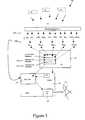
- the laser platformincludes a computer-linked control system 18 that utilizes software to compute an appropriate laser ablation shot file based upon optical zone size and other input parameters entered by the surgeon.
- the laser platformalso includes hardware in the form of beam shaping and steering optics that react to instructions from the control system to deliver the shot file in the appropriate manner to the cornea.
- the laser platformis a “smart” device, so to speak, because it is there that both information processing and treatment execution occur.
- the laser platformis capable of receiving a computer-readable medium 20 having both enablement and instructional software stored therein which can be processed by the computer system in the laser platform.
- the laser platformis burdened with computer hardware and software adding to the complexity and cost of every unit.
- the computer-readable mediummay be in the form of a single use enablement card, for example, as described in U.S. Pat. Nos. 6,296,634 and 6,364,873.
- Such enablement cardsare typically purchased by a user, and generate a set per-procedure fee for the laser manufacturer.
- Each treatment procedurerequires a card, while the laser system continues to require the necessary computer hardware and software as mentioned above.
- the laser systemlacks flexibility and is no less burdened than described above.
- there are many aspects of the laser platformthat can malfunction, increasing the risk of surgical downtime for the user. Trained technicians having skills in multiple technical fields are required to maintain and service the multi-component laser platforms.
- the inventionis generally directed to apparatus and methods involved in the control of a laser vision correction system, and a system incorporating these controls.
- An embodiment of the inventionis directed to a device-readable medium on or in which is stored a pre-programmed, readable, first corrective instruction reference.
- This instruction referencecorresponds to an encoded customized corrective instruction.
- customized corrective instructionrefers to the number, sequence, and placement of laser pulses for a particular laser vision correction treatment.
- the instructionis determined by a calculation module located external to the medium and to the laser platform, and is executable by the laser platform of a laser vision correction system.
- the customized corrective instructionis determined in a manner that will be described in greater detail below.
- a particular customized corrective instructionis then encoded in such a manner that the instruction can be executed by the laser platform upon recognition of the corresponding instruction reference stored in or on the medium.
- the first corrective instruction reference stored in or on the mediumis a necessary and sufficient component for enabling the laser platform to execute the customized instruction when the instruction reference is properly recognized.
- the first instruction referenceis a necessary but not sufficient component for allowing enablement and execution of the customized instruction by the laser platform.
- a second, readable corrective instruction referenceis stored in or on the medium and in combination with the first corrective instruction reference, is sufficient for enabling execution of the customized instruction.
- the second instruction referencewill correspond to an encoded user ID or laser platform ID which will be associated with the customized instruction.
- the mediummay have stored therein a second pre-programmed instruction reference and a third pre-programmed instruction reference, corresponding to a user ID and a laser platform ID, in addition to the first instruction reference corresponding to the customized corrective instruction.
- all three matching instruction referencesare necessary and, in combination, sufficient components for enabling the execution of the customized instruction by the laser platform.
- the total data storage requirement for any or all of the instruction references in combination, along with any other information stored in the mediumpreferably will not exceed 1000 bytes of storage space.
- the mediumincludes a laser platform disablement feature that limits a preset number of uses of the laser platform for each readable medium unit.
- the mediumincludes a beam sizing and shaping feature to provide a desired beam diameter and beam energy profile for ablating a corneal surface and/or facilitating beam diagnostics.
- a laser vision correction systemincludes a calculation module that can receive input data relating at least to a refractive defect of a patient's eye and calculate a customized corrective instruction based, at least in part, upon the input data.
- the term calculation modulerefers either to a hardware device, computer-executable software which performs all pertinent aspects of an ablation treatment algorithm, or a combination of hardware, software, and/or firmware for determining the customized corrective instruction.
- the calculated customized corrective instructionis then encoded such that the encryption will allow a matching correspondence to a pre-programmed first corrective instruction reference that is stored in or on a device-readable medium.
- the systemfurther includes a laser platform that can receive the readable medium and execute the customized corrective instruction, as a necessary condition, only when the first corrective instruction reference corresponding to the encoded customized corrective instruction is recognized by the laser platform.
- the calculation moduleis external to the laser platform and preferably resides in a diagnostic platform that is used to generate at least some of the input data.
- the customized corrective instruction calculated by the calculation modulemay include more than one particular corrective instruction for each of a variety of laser vision corrective treatments.
- the calculation modulemay generate three different corrective instructions for myopia treatments, or, two different instructions for hyperopia treatments, that, when encoded, correspond to the first corrective instruction reference on the storage medium, thus potentially providing the user with a choice of appropriate treatment options.
- the systemincludes a graphical user interface (GUI) that is operably associated with the laser platform, along with a configuration file that is also operably associated with the laser platform and the GUI.
- GUIgraphical user interface
- the configuration filewill recognize the instruction reference corresponding to the customized corrective instruction and will then initiate a particular GUI associated with the one or more matched, customized corrective instructions.
- the GUIwill then allow the user to input information that will result in the selection of a single matching instruction reference recognized by the configuration file in the laser platform that will enable and allow the laser platform to execute the particular customized refractive instruction.
- a method for controlling a laser vision correction systemincludes providing a device-readable medium having the attributes of the device-readable medium set forth hereinabove, for use in a laser platform to execute a particular laser vision correction procedure. It further includes providing the medium to a third party on a remunerative basis; and, structuring the remuneration as a function of type and/or number of corresponding instruction references supplied in the medium.
- Another method embodiment for controlling a laser vision correction systeminvolves determining a customized corrective instruction for correcting an ophthalmic refractive defect, encoding the instruction, providing a transferable device-readable medium that includes a pre-programmed, first corrective instruction reference which corresponds to the encoded instruction, and providing a laser platform that can receive the transferable medium and recognize the corresponding first instruction reference as a necessary condition for enabling execution of the customized corrective instruction.
- the methodfurther includes providing a GUI that is operably connected with the laser platform and which is configured according to the instruction reference corresponding to the encoded instruction.
- the methodincludes providing either or both of an encoded user ID and an encoded laser platform ID, and providing associated second and/or third corresponding instruction references in the transferable medium which are recognizable as necessary and, perhaps, sufficient conditions for allowing execution of the customized corrective instruction.
- second and/or third instruction referenceother corresponding codes can be stored in the medium; e.g., iris pattern codes.
- the medium storage structuremay further be writeable such that the medium could be inserted into a component of the diagnostic platform to directly receive specific encoded or uncoded data.
- FIG. 1is a block diagram of a prior art laser vision correction system
- FIG. 2is a block diagram of a laser vision correction system according to an embodiment of the invention.
- FIG. 3is a block diagram of a more detailed illustration of the system of FIG. 2;
- FIG. 4is a front view line drawing of a device-readable enablement medium according to a preferred embodiment of the invention.
- FIG. 5is a drawing showing a beam shaping feature of the enablement medium according to a preferred embodiment of the invention.
- FIG. 6is a more detailed illustration of the beam shaping feature of the enablement medium according to an embodiment of the invention.
- FIG. 7is a graphical illustration of a laser beam intensity profile produced by the beam shaping feature of the enablement medium according to an embodiment of the invention.
- FIG. 8is a front view illustration of an alignment and positioning apparatus for the enablement medium according to an embodiment of the invention.
- FIG. 2shows a simplified block diagram of a laser vision correction system 100 according to a preferred embodiment of the invention.
- the basic components of the systeminclude a calculation module 150 , a laser platform 102 , and a device readable medium 134 that is transferable to and readable by the laser platform 102 .
- the readable medium 134is preferably in the form of a card similar in size and shape to a credit card.
- the card medium 134includes a section 133 for storing data that can be read by an appropriate card reader 130 located in the laser platform 102 .
- the calculation module 150receives input data 151 from what is referred to as a diagnostic platform 105 .
- the diagnostic platform 105can be comprised of a single diagnostic instrument that provides diagnostic information relating to a patient's refractive defect, or any combination of various diagnostic instruments and/or other forms of outcome influencing information that a surgeon may wish to enter.
- the calculation module 150is an executable computer software routine that runs in a diagnostic wavefront sensing device 105 . Wavefront measurement information is fed into the calculation module 150 which then uses that information to calculate one or more appropriate laser treatments. These treatments are referred to herein as customized corrective instructions 120 . These instructions ultimately instruct a fire control system (not shown) in the laser platform 102 where to direct a series of laser pulses on the patient's cornea to effect the appropriate laser vision correction treatment.
- a device-readable medium 134as preferably illustrated in FIG. 4, is utilized.
- the medium 134includes a data storage section 133 that is preprogrammed with a first corrective instruction reference 132 .
- the first corrective instruction reference 132will match an encryption code 120 ′ corresponding to a customized corrective instruction 120 generated by the calculation module 150 based upon the input data 151 .
- the laser platform 102is equipped with a device-readable medium reader 130 which acts in one capacity as a lock and key mechanism, so to speak.
- a necessary condition enabling the laser platform 102 to execute the customized corrective instruction 120will be a recognition of the first corrective instruction reference 132 corresponding to the encoded customized corrective instruction 120 ′.
- This recognitionis preferably accomplished in a configuration file 119 operably associated with, and preferably located in, the laser platform 102 .
- a graphical user interface 144is operably associated with the laser platform 102 and the configuration file 119 to further enable execution of the customized corrective instruction 120 , as will be discussed in greater detail below.
- FIG. 3A further illustration of a preferred embodiment of the laser vision correction system 100 is illustrated in FIG. 3 and is described as follows.
- a laser vision correction treatment 190in the form of a programmed series of ablating laser pulses will be directed to a patient's eye 192 to reshape the cornea in an attempt to correct a refractive defect of the patient's eye.
- Laser vision corrective surgeryis typically provided, or being developed for, myopia, hyperopia, presbyopia, retreatment, customized treatment, and other conditions, as appreciated by those skilled in the art.
- the determination of a particular refractive defectstarts with diagnostic information about the patient's eye and its visual quality.
- This diagnostic input data 151can be generated by one or more diagnostic devices including wavefront sensors, topography devices, ultrasonic pachymeters, optical coherence tomography (OCT) devices, refractometers, slit lamp ophthalmoscopes (SLOs), iris pattern recognition apparatus, and others, for example, well appreciated by those skilled in the art, and by other pertinent information that may be supplied by the practitioner including surgical environmental conditions, particular patient data, surgeon factors, and others.
- the diagnostic platform 105not a part of the invention per se, is used to collectively refer to any or all of the appropriate means for providing diagnostic information indicative of the patient's refractive defect.
- the appropriate input data 151is fed to a calculation module 150 .
- the calculation module 150comprises software that uses the input data 151 to determine one or more of an appropriate myopia treatment (MY n ), hyperopia treatment (HYP n ), presbyopia treatment (PBY n ,), etc., 120 as shown.
- MY nmyopia treatment
- HOP nhyperopia treatment
- PBY npresbyopia treatment
- a Zywave® wavefront sensor(Bausch & Lomb Incorporated, Rochester, N.Y.) includes a computer that runs software known in the industry as Zylink® ablation computation software.
- Zylinkuses the wavefront diagnostic data to determine an appropriate shot file for execution by a laser platform such as a Technolas 217Z® laser.
- the calculation module 150may calculate one myopia treatment (MY 1 ,) based upon a particular set of input data, and a different customized myopia treatment (MY 2 ) based upon a different set of input data.
- hyperopia treatmentspresbyopic treatments, retreatments, customized treatments, or other treatments can be determined by the calculation module.
- theseare listed as HYP 1 , HYP 2 . . . , MY 1 , MY 2 . . . , PBY 1 , PBY 2 . . . , etc., in the FIG. 3 .
- Each of these calculated treatmentsbecomes a customized corrective instruction 120 that is executable by an enabled laser platform 102 upon appropriate command.
- the laser platform 102has become a “dumb black box,” so to speak, because the instruction for execution by the laser platform has been calculated externally of the laser platform.
- the device-readable medium 134has a data storage section 133 in or on which is pre-programmed the first corrective instruction reference 132 .
- the first corrective instruction reference 132corresponds to one or more of the encoded customized corrective instructions 120 ′ determined by the calculation module 150 .
- the data storage section 133 of the card medium 134preferably has a data storage capacity of 1000 bytes or less making the card medium a relatively simple and inexpensive component suitable for single or pre-set limited use.
- the laser platform 102is equipped with a card reader 130 .
- the laser platform 102further includes a configuration file 119 .
- the configuration file 119is preferably a hardware file that is adapted to recognize the instruction reference 132 on the card medium 134 corresponding to the encoded customized correction instruction 120 ′. Recognition of the first instruction reference by the configuration file 119 is a necessary condition for enabling the laser platform 102 to execute the predetermined customized corrective instruction 120 .
- the calculation module 150will generate a single myopia ablation treatment 120 based upon particular input data 151 .
- the user of the laser systemwill then need a card medium 134 that has a first instruction reference 132 stored therein which corresponds to the code 120 ′ associated with the customized corrective instruction 120 .
- Use of the card medium in the laser platform and recognition of the corresponding instruction reference by the configuration filewill unlock the laser platform for use and will enable the laser platform to carry out the particular customized corrective instruction 120 .
- Laser corrective surgerytypically requires specific input from the surgeon; for example, the size of the optical zone (OZ) which is related to the depth of ablation for a particular treatment and further which is a determining factor as to whether a particular treatment can safely be carried out.
- This type of infornationis usually input into the system by the surgeon via a keypad 141 and a graphical user interface (GUI) 144 associated with the laser platform 102 .
- GUIgraphical user interface
- the configuration file 119upon recognition of a first corrective instruction reference 132 corresponding to an encoded customized corrective instruction 120 ′, will call up an appropriate graphical user interface 144 which will allow the surgeon to input or confirm any deterministic data for the treatment.
- a customized corrective instruction for a myopia treatmentmay generate a different graphical user interface screen than a customized corrective instruction for a hyperopia treatment, and so on.
- it is a necessary condition for operation of the laser platformthat the first instruction reference 132 match the customized corrective instruction code 120 ′.
- at least one second instruction reference 123 stored in the card medium 134will match a second code 123 ′ and this will be a necessary and sufficient condition for enabling the laser platform 102 to execute the instruction 120 .
- the second instruction reference 123may necessarily have to match a user ID code along with the matching first instruction reference 132 in order to unlock and enable the laser platform.
- a third instruction reference 125 stored in the card medium 134must necessarily match a laser platform ID such that only all three matching instruction references 132 , 123 , 125 are necessary and sufficient conditions for enabling the laser platform. In this manner, only an identified user may use an identified laser platform to carry out a particular customized corrective instruction.
- Other second, third, and/or more instruction referencesmay be stored in the card medium.
- an instruction referencemay correspond to an iris pattern code, or to an encoded LASIK flap thickness measurement.
- a microkeratome platformmay be adapted to accept the card medium and write to the storage section a lamellar code indicative of or relating to flap thickness. When the card medium is then engaged with the laser platform, recognition of a particular lamellar code may be a necessary condition for enabling the laser platform.
- the card medium 134will be equipped with a laser platform disablement feature 135 .
- the disablement feature 135can be an electronic circuit or other well-known means that can be configured in such a manner to preset the number of uses of the card medium to enable the laser platform.
- each card medium 134could be preset to disable the laser platform after each single use.
- the card medium 134could be programmed for two uses per card in the form of a single use on each eye of the patient. A new card medium will be required for each use of the laser, thus setting up an annuity structure for the card provider.
- FIG. 4another preferred aspect of the invention shows the card medium 134 with one or more apertures 304 , 302 , 307 , in an aperture mask 311 .
- Each apertureshapes and/or characterizes the laser beam passing through the aperture on its way to the target surface.
- one of the apertures 304referred to herein as a “soft-spot” aperture, has a central, directly transmitting aperture portion 305 surrounded by a plurality of smaller, diffracting apertures 306 .
- the directly transmitting portion 305 of the aperture 304essentially determines a beam spot diameter, while the diffractively transmitting portion 306 generates a particular beam energy profile which, in an exemplary case, is a soft-spot profile.
- FIG. 7illustrates a soft-spot profile 400 which has the form of a truncated Gaussian distribution.
- the directly transmitting portion 305 of aperture 304has a diameter of 3 mm for directly transmitting the laser beam upon proper alignment, producing a 2 mm beam diameter spot on the target surface.
- Another aperture 307is also a soft-spot aperture, preferably having a directly transmitting portion diameter of about 1.5 mm and delivering a 1 mm beam on target.
- Aperture 302contains only a directly transmitting portion used for beam fluence calibration.
- the card medium 134preferably has two soft-spot apertures 304 , 307 of different overall diameters, and a hard spot aperture 302 , as shown in FIG. 5 .
- two different beam spot sizescan selectively be projected onto the exposed cornea surface.
- the two spot sizes on the corneal surfacewill be 2 mm and 1 mm.
- An automatic, pressure based mechanism 300is used to position and align the card 134 in the laser beam path in the module 102 .
- Fixation points 222 x,y and pressure points 224 x,yare used as follows: the fixation points 222 x,y comprise three hardened cylinder pins that are press fit with high accuracy into a card holder 226 .
- the card 134is pushed into the holder 226 from right to left (as viewed in FIG. 7) until the left edge 227 of the card touches fixation point 222 x and the bottom edge 229 of the card touches fixation points 222 yl and 222 y2 .
- the cardis fixated against the fixation points by pressure points 224 x , 224 y which, preferably, are springs.
- a preferable truncated Gaussian ablation profile (or spatial intensity distribution) 400 passed by the 3 mm soft-spot aperture 304is shown.
- the profileis normalized and only one-half the profile 400 is illustrated, solely for simplicity of the drawing, it being understood that the full profile 400 would be as if mirrored about the ordinate axis of FIG. 7 .
- the 1 mm aperture 307would pass a similar, but narrower, profile.
- a center portion 401 of the aperture profile 400is flat or substantially flat, whereas an edge 402 of the profile 400 is continuous with the portion 401 and is rounded.
- the portion 401is preferably symmetric about the radius of the profile and extends across about 60-80%, and, more preferably, across about 65-70% of the profile 400 .
- the profile 400preferably quickly drops off or diminishes as a substantially square, vertical, or truncated edge 406 .
- the ablation threshold and any variations in itare known in the art.
- the amount of energy falling below the threshold for ablationis preferably about 5% or less of the total energy encompassed by the profile 400 .
- a preferred embodimentis a method for controlling a laser vision correction system that involves providing, to a third party, a device-readable medium ( 134 ) as set forth hereinabove, for use in a laser platform ( 102 ) to enable and execute a particular customized corrective instruction. Since provision of the card medium forms the basis of an annuity model for the card medium provider (typically the laser manufacturer), a single or preset use limitation ( 135 ) enabled by the card medium ( 134 ) promotes business transaction between the card supplier and the laser user. This is commonly referred to as the “per-procedure” model.
- the remunerative structuremay be set according to the type and/or number of customized corrective instructions corresponding to the first instruction reference supplied on a particular card medium. For example, a physician may plan to perform 1,000 myopia laser procedures within a general patient base, and 100 customized myopia procedures within a select patient base. Based upon the input data, the calculation module may generate two different myopia treatment algorithms associated, respectively, with a non-customized myopia treatment and a customized myopia treatment. Accordingly, a user may purchase 1,000 cards containing a first matching instruction reference that will enable the laser platform to execute only a non-customized myopia treatment at some nominal cost per card unit.
- the usermay purchase 100 cards, each of which has a first matching instruction reference that will be recognized to enable the laser platform to execute a customized myopia treatment. These cards will have a different cost per card unit than the non-customized enabling cards.
- the remunerative basis of the card transactioncan be structured upon the type of treatment, number of treatments, or other factors enabled by the particular code or codes stored on the card medium.
- a related embodimentdescribes a method for controlling a laser vision correction system that involves generating a customized corrective instruction for correcting an ophthalmic refractive defect based upon diagnostic information indicative of that refractive defect; encoding the customized corrective instruction; providing a transferable, device-readable medium having a storage structure that contains a first corrective instruction reference that corresponds to the encoded customized corrective instruction; and providing, in a laser platform that is adapted to receive the device-readable medium, a means for recognizing the first instruction reference as a necessary condition for enablement and execution of the customized corrective instruction.
- the recognition meansincludes a configuration file in the laser platform that upon recognition of the first instruction reference and, optionally, a second and/or third matching instruction reference which correspond to a user ID and/or a laser platform ID, for example, calls up a particular graphical user interface for additional data input by the surgeon.
- the apparatus described hereinabovewill, for example, position the card medium in the laser beam path and deliver a series of desired laser beam pulses to the patient's cornea to effect the desired treatment for correcting or at least improving upon the patient's refractive defect.
- the card medium 134 including the first instruction reference 132has greatly enhanced the flexibility of the vision correction system on several fronts over the prior art technology.
- a single enablement-type cardwas required for each procedure at a set fee per card unit
- a variety of pre-programmed enablement/instruction cards priced according to card/system enablement featuresare made available for use in a simplified laser platform.
Landscapes
- Health & Medical Sciences (AREA)
- Ophthalmology & Optometry (AREA)
- Life Sciences & Earth Sciences (AREA)
- Animal Behavior & Ethology (AREA)
- Optics & Photonics (AREA)
- Surgery (AREA)
- Engineering & Computer Science (AREA)
- Biomedical Technology (AREA)
- Heart & Thoracic Surgery (AREA)
- Vascular Medicine (AREA)
- Physics & Mathematics (AREA)
- Nuclear Medicine, Radiotherapy & Molecular Imaging (AREA)
- General Health & Medical Sciences (AREA)
- Public Health (AREA)
- Veterinary Medicine (AREA)
- Laser Surgery Devices (AREA)
- Radiation-Therapy Devices (AREA)
- Preparing Plates And Mask In Photomechanical Process (AREA)
- Length Measuring Devices By Optical Means (AREA)
- Optical Recording Or Reproduction (AREA)
- Lasers (AREA)
Abstract
Description
Claims (47)
Priority Applications (17)
| Application Number | Priority Date | Filing Date | Title |
|---|---|---|---|
| US10/184,441US6814729B2 (en) | 2002-06-27 | 2002-06-27 | Laser vision correction apparatus and control method |
| DE07103486TDE07103486T1 (en) | 2002-06-27 | 2003-06-26 | Laser device for visual correction and control method |
| TW092117419ATWI301064B (en) | 2002-06-27 | 2003-06-26 | Laser vision correction apparatus and control method |
| EP07103486AEP1785111A3 (en) | 2002-06-27 | 2003-06-26 | Laser vision correction apparatus and control method |
| CNB038150735ACN100417366C (en) | 2002-06-27 | 2003-06-26 | Laser vision correction apparatus and control method |
| KR1020117031515AKR20120014066A (en) | 2002-06-27 | 2003-06-26 | Laser vision correction device |
| BRPI0312223ABRPI0312223B8 (en) | 2002-06-27 | 2003-06-26 | device readable medium that includes a storage structure, laser vision correction system, and method for controlling the same. |
| EP03761526AEP1515671B1 (en) | 2002-06-27 | 2003-06-26 | Laser vision correction apparatus |
| ES03761526TES2282669T3 (en) | 2002-06-27 | 2003-06-26 | APPARATUS FOR CORRECTION OF LASER VISION. |
| PCT/EP2003/006776WO2004002381A1 (en) | 2002-06-27 | 2003-06-26 | Laser vision correction apparatus and control method |
| ES07103486TES2286962T1 (en) | 2002-06-27 | 2003-06-26 | APPARATUS FOR CORRECTION OF LASER VISION AND CONTROL METHOD. |
| AU2003246598AAU2003246598B2 (en) | 2002-06-27 | 2003-06-26 | Laser vision correction apparatus and control method |
| DE60312329TDE60312329T2 (en) | 2002-06-27 | 2003-06-26 | LASERVISUSKORREKTURAPPARAT |
| KR1020047021025AKR101113396B1 (en) | 2002-06-27 | 2003-06-26 | Laser vision correction apparatus |
| JP2004516702AJP2005530572A (en) | 2002-06-27 | 2003-06-26 | Laser vision correction apparatus and control method |
| CA002490650ACA2490650C (en) | 2002-06-27 | 2003-06-26 | Laser vision correction apparatus and control method |
| AT03761526TATE355810T1 (en) | 2002-06-27 | 2003-06-26 | LASER VISION CORRECTION APPARATUS |
Applications Claiming Priority (1)
| Application Number | Priority Date | Filing Date | Title |
|---|---|---|---|
| US10/184,441US6814729B2 (en) | 2002-06-27 | 2002-06-27 | Laser vision correction apparatus and control method |
Publications (2)
| Publication Number | Publication Date |
|---|---|
| US20040002695A1 US20040002695A1 (en) | 2004-01-01 |
| US6814729B2true US6814729B2 (en) | 2004-11-09 |
Family
ID=29779357
Family Applications (1)
| Application Number | Title | Priority Date | Filing Date |
|---|---|---|---|
| US10/184,441Expired - LifetimeUS6814729B2 (en) | 2002-06-27 | 2002-06-27 | Laser vision correction apparatus and control method |
Country Status (13)
| Country | Link |
|---|---|
| US (1) | US6814729B2 (en) |
| EP (2) | EP1785111A3 (en) |
| JP (1) | JP2005530572A (en) |
| KR (2) | KR101113396B1 (en) |
| CN (1) | CN100417366C (en) |
| AT (1) | ATE355810T1 (en) |
| AU (1) | AU2003246598B2 (en) |
| BR (1) | BRPI0312223B8 (en) |
| CA (1) | CA2490650C (en) |
| DE (2) | DE60312329T2 (en) |
| ES (2) | ES2282669T3 (en) |
| TW (1) | TWI301064B (en) |
| WO (1) | WO2004002381A1 (en) |
Cited By (8)
| Publication number | Priority date | Publication date | Assignee | Title |
|---|---|---|---|---|
| US20050273088A1 (en)* | 2002-06-27 | 2005-12-08 | Gerhard Youssefi | Myopia correction enhancing biodynamic ablation |
| US20060235369A1 (en)* | 2005-04-14 | 2006-10-19 | Macrae Scott | System and method for treating vision refractive errors |
| US20060264916A1 (en)* | 2005-05-19 | 2006-11-23 | Visx, Incorporated. | Training enhanced pseudo accommodation methods, systems and devices for mitigation of presbyopia |
| US7226443B1 (en)* | 2003-11-07 | 2007-06-05 | Alcon Refractivehorizons, Inc. | Optimization of ablation correction of an optical system and associated methods |
| US20080058778A1 (en)* | 2006-08-31 | 2008-03-06 | Liedel Kevin K | Performance assessment system for refractive lasers and associated methods |
| US7988290B2 (en) | 2007-06-27 | 2011-08-02 | AMO Wavefront Sciences LLC. | Systems and methods for measuring the shape and location of an object |
| US20120150162A1 (en)* | 2010-10-19 | 2012-06-14 | Keith Andrew Walter | One-card presbyopia systems and related methods |
| US10966748B2 (en) | 2017-11-27 | 2021-04-06 | Rafic Saleh | Endoscopic snare |
Families Citing this family (8)
| Publication number | Priority date | Publication date | Assignee | Title |
|---|---|---|---|---|
| US8394084B2 (en)* | 2005-01-10 | 2013-03-12 | Optimedica Corporation | Apparatus for patterned plasma-mediated laser trephination of the lens capsule and three dimensional phaco-segmentation |
| AU2016203089B2 (en)* | 2005-01-10 | 2017-04-06 | Amo Development, Llc | Method and apparatus for patterned plasma-mediated laser trephination of the lens capsule and three dimensional phaco-segmentation |
| US20100174151A1 (en)* | 2006-03-27 | 2010-07-08 | Francesco Peluso | Modular expandable multifunction machine with automatic recognition of actuators for aesthetic and/or rehabilitative treatments |
| ES2833281T3 (en)* | 2012-02-25 | 2021-06-14 | Thrufocus Optics Inc | Devices to improve eyesight using laser photomyosis |
| CA2906976A1 (en)* | 2013-05-16 | 2014-11-20 | Wavelight Gmbh | Touchless user interface for ophthalmic devices |
| EP3697356B1 (en)* | 2017-10-17 | 2023-02-15 | Alcon Inc. | Customized ophthalmic surgical profiles |
| CN109481249A (en)* | 2019-01-15 | 2019-03-19 | 广州市安狄健康信息咨询有限公司 | A kind of method and device of Intelligent eyesight correction |
| US11867807B2 (en)* | 2021-09-01 | 2024-01-09 | GE Precision Healthcare LLC | System and methods for beamforming sound speed selection |
Citations (9)
| Publication number | Priority date | Publication date | Assignee | Title |
|---|---|---|---|---|
| US4669466A (en)* | 1985-01-16 | 1987-06-02 | Lri L.P. | Method and apparatus for analysis and correction of abnormal refractive errors of the eye |
| EP0280414A1 (en) | 1987-02-02 | 1988-08-31 | Taunton Technologies, Inc. | Sculpture apparatus for correcting curvature of the cornea |
| US5683379A (en) | 1992-10-01 | 1997-11-04 | Chiron Technolas Gmbh Ophthalmologische Systeme | Apparatus for modifying the surface of the eye through large beam laser polishing and method of controlling the apparatus |
| US5891132A (en) | 1996-05-30 | 1999-04-06 | Chiron Technolas Gmbh Opthalmologische Systeme | Distributed excimer laser surgery system |
| US6090100A (en) | 1992-10-01 | 2000-07-18 | Chiron Technolas Gmbh Ophthalmologische Systeme | Excimer laser system for correction of vision with reduced thermal effects |
| US6106513A (en)* | 1991-03-08 | 2000-08-22 | Affymetrix, Inc. | Opthalmological surgery technique with active patient data card |
| EP1044755A2 (en) | 1999-03-30 | 2000-10-18 | Nidek Co., Ltd. | Laser treatment apparatus |
| US6299309B1 (en) | 1999-03-10 | 2001-10-09 | Luis Antonio Ruiz | Interactive corrective eye surgery system with topography and laser system interface |
| US20030073984A1 (en) | 2001-10-12 | 2003-04-17 | Nidek Co., Ltd. | Corneal-ablation-data determining apparatus and a corneal surgery apparatus |
Family Cites Families (2)
| Publication number | Priority date | Publication date | Assignee | Title |
|---|---|---|---|---|
| CA2105629A1 (en) | 1992-09-14 | 1994-03-15 | Robert S. Becker | Potentiation of immunogenic response |
| AU777228B2 (en)* | 1999-10-21 | 2004-10-07 | Technolas Gmbh Ophthalmologische Systeme | Method and apparatus for opthalmic refractive correction |
- 2002
- 2002-06-27USUS10/184,441patent/US6814729B2/ennot_activeExpired - Lifetime
- 2003
- 2003-06-26DEDE60312329Tpatent/DE60312329T2/ennot_activeExpired - Lifetime
- 2003-06-26DEDE07103486Tpatent/DE07103486T1/enactivePending
- 2003-06-26CACA002490650Apatent/CA2490650C/ennot_activeExpired - Lifetime
- 2003-06-26EPEP07103486Apatent/EP1785111A3/ennot_activeWithdrawn
- 2003-06-26ESES03761526Tpatent/ES2282669T3/ennot_activeExpired - Lifetime
- 2003-06-26AUAU2003246598Apatent/AU2003246598B2/ennot_activeCeased
- 2003-06-26JPJP2004516702Apatent/JP2005530572A/enactivePending
- 2003-06-26KRKR1020047021025Apatent/KR101113396B1/ennot_activeExpired - Fee Related
- 2003-06-26KRKR1020117031515Apatent/KR20120014066A/ennot_activeCeased
- 2003-06-26CNCNB038150735Apatent/CN100417366C/ennot_activeExpired - Lifetime
- 2003-06-26EPEP03761526Apatent/EP1515671B1/ennot_activeExpired - Lifetime
- 2003-06-26WOPCT/EP2003/006776patent/WO2004002381A1/enactiveIP Right Grant
- 2003-06-26ESES07103486Tpatent/ES2286962T1/enactivePending
- 2003-06-26TWTW092117419Apatent/TWI301064B/ennot_activeIP Right Cessation
- 2003-06-26BRBRPI0312223Apatent/BRPI0312223B8/ennot_activeIP Right Cessation
- 2003-06-26ATAT03761526Tpatent/ATE355810T1/ennot_activeIP Right Cessation
Patent Citations (13)
| Publication number | Priority date | Publication date | Assignee | Title |
|---|---|---|---|---|
| US4669466A (en)* | 1985-01-16 | 1987-06-02 | Lri L.P. | Method and apparatus for analysis and correction of abnormal refractive errors of the eye |
| EP0280414A1 (en) | 1987-02-02 | 1988-08-31 | Taunton Technologies, Inc. | Sculpture apparatus for correcting curvature of the cornea |
| US6296634B1 (en) | 1991-03-08 | 2001-10-02 | Visx, Incorporated | Ophthalmological surgery technique with active patient data card |
| US6106513A (en)* | 1991-03-08 | 2000-08-22 | Affymetrix, Inc. | Opthalmological surgery technique with active patient data card |
| US6364873B1 (en) | 1991-03-08 | 2002-04-02 | Visx Incorporated | Ophthalmological surgery technique with active patient data card |
| US5827264A (en) | 1992-10-01 | 1998-10-27 | Chiron Technolas Gmbh Ophthalmologische Systeme | Method of controlling apparatus for modifying the surface of the eye through large beam laser polishing |
| US6090100A (en) | 1992-10-01 | 2000-07-18 | Chiron Technolas Gmbh Ophthalmologische Systeme | Excimer laser system for correction of vision with reduced thermal effects |
| US5683379A (en) | 1992-10-01 | 1997-11-04 | Chiron Technolas Gmbh Ophthalmologische Systeme | Apparatus for modifying the surface of the eye through large beam laser polishing and method of controlling the apparatus |
| US5891132A (en) | 1996-05-30 | 1999-04-06 | Chiron Technolas Gmbh Opthalmologische Systeme | Distributed excimer laser surgery system |
| US6139542A (en) | 1996-05-30 | 2000-10-31 | Chiron Technolas Gmbh Opthalmologische Systeme | Distributed excimer laser surgery system |
| US6299309B1 (en) | 1999-03-10 | 2001-10-09 | Luis Antonio Ruiz | Interactive corrective eye surgery system with topography and laser system interface |
| EP1044755A2 (en) | 1999-03-30 | 2000-10-18 | Nidek Co., Ltd. | Laser treatment apparatus |
| US20030073984A1 (en) | 2001-10-12 | 2003-04-17 | Nidek Co., Ltd. | Corneal-ablation-data determining apparatus and a corneal surgery apparatus |
Non-Patent Citations (4)
| Title |
|---|
| Knorz et al., "Topographically-Guided Laser In Situ Keratomileusis to Treat Corneal Irregularities," American Academy of Ophthalmology, vol. 107, No. 6, Jun. 2000, pp. 1138-1143. |
| Knorz, et al., "Treatment of Myopia and Myopic Astigmatism by Customized Laser In Situ Keratomileusis Based on Corneal Topography," American Academy of Ophthalmology, vol. 107, No. 11, Nov. 2000, pp. 2072-2076. |
| Mrochen, et al., "Wavefront-Guided Laser In Situ Keratomileusis: Early Results in Three Eyes," Journal of Refractive Surgery, vol. 16, No. 2, Mar./Apr. 2000, pp. 116-121. |
| US Pub. No. 2002/0091376A1 Entitled "Ophthalmological Surgery Technique with Active Patient Data Card" by McMillen, published Jul. 11, 2002. |
Cited By (17)
| Publication number | Priority date | Publication date | Assignee | Title |
|---|---|---|---|---|
| AU2003249884B2 (en)* | 2002-06-27 | 2008-08-14 | Technolas Gmbh Ophthalmologishe Systeme | Myopia correction enhancing biodynamic ablation |
| US20050273088A1 (en)* | 2002-06-27 | 2005-12-08 | Gerhard Youssefi | Myopia correction enhancing biodynamic ablation |
| US7226443B1 (en)* | 2003-11-07 | 2007-06-05 | Alcon Refractivehorizons, Inc. | Optimization of ablation correction of an optical system and associated methods |
| US8273077B2 (en) | 2005-04-14 | 2012-09-25 | University Of Rochester | System and method for treating vision refractive errors |
| US20060235369A1 (en)* | 2005-04-14 | 2006-10-19 | Macrae Scott | System and method for treating vision refractive errors |
| US20060264916A1 (en)* | 2005-05-19 | 2006-11-23 | Visx, Incorporated. | Training enhanced pseudo accommodation methods, systems and devices for mitigation of presbyopia |
| US7413566B2 (en)* | 2005-05-19 | 2008-08-19 | Amo Manufacturing Usa, Llc | Training enhanced pseudo accommodation methods, systems and devices for mitigation of presbyopia |
| US20090036981A1 (en)* | 2005-05-19 | 2009-02-05 | Amo Manufacturing Usa, Llc | Training enhanced pseudo accommodation methods, systems and devices for mitigation of presbyopia |
| US8079367B2 (en) | 2005-05-19 | 2011-12-20 | Amo Manufacturing Usa, Llc. | Training enhanced pseudo accommodation methods, systems and devices for mitigation of presbyopia |
| US20080058778A1 (en)* | 2006-08-31 | 2008-03-06 | Liedel Kevin K | Performance assessment system for refractive lasers and associated methods |
| US7988290B2 (en) | 2007-06-27 | 2011-08-02 | AMO Wavefront Sciences LLC. | Systems and methods for measuring the shape and location of an object |
| US20120150162A1 (en)* | 2010-10-19 | 2012-06-14 | Keith Andrew Walter | One-card presbyopia systems and related methods |
| US9155659B2 (en)* | 2010-10-19 | 2015-10-13 | Wake Forest University Health Sciences | One-card presbyopia treatment laser systems and related methods |
| US10058452B2 (en) | 2010-10-19 | 2018-08-28 | Wake Forest University Health Sciences | One-card presbyopia systems and related methods |
| US20180333302A1 (en)* | 2010-10-19 | 2018-11-22 | Wake Forest University Health Sciences | One-card presbyopia systems and related methods |
| US11033430B2 (en)* | 2010-10-19 | 2021-06-15 | Wake Forest University Health Sciences | One-card presbyopia systems and related methods |
| US10966748B2 (en) | 2017-11-27 | 2021-04-06 | Rafic Saleh | Endoscopic snare |
Also Published As
| Publication number | Publication date |
|---|---|
| BR0312223A (en) | 2005-04-12 |
| ATE355810T1 (en) | 2007-03-15 |
| CN1744867A (en) | 2006-03-08 |
| AU2003246598A1 (en) | 2004-01-19 |
| WO2004002381A1 (en) | 2004-01-08 |
| ES2286962T1 (en) | 2007-12-16 |
| CA2490650A1 (en) | 2004-01-08 |
| ES2282669T3 (en) | 2007-10-16 |
| KR20060069208A (en) | 2006-06-21 |
| AU2003246598B2 (en) | 2007-12-13 |
| CA2490650C (en) | 2009-04-14 |
| KR101113396B1 (en) | 2012-02-29 |
| DE60312329T2 (en) | 2007-11-08 |
| DE07103486T1 (en) | 2007-11-15 |
| JP2005530572A (en) | 2005-10-13 |
| EP1785111A3 (en) | 2010-11-10 |
| EP1515671A1 (en) | 2005-03-23 |
| TW200407102A (en) | 2004-05-16 |
| CN100417366C (en) | 2008-09-10 |
| EP1515671B1 (en) | 2007-03-07 |
| KR20120014066A (en) | 2012-02-15 |
| US20040002695A1 (en) | 2004-01-01 |
| BRPI0312223B8 (en) | 2021-06-22 |
| BRPI0312223B1 (en) | 2017-04-25 |
| EP1785111A2 (en) | 2007-05-16 |
| DE60312329D1 (en) | 2007-04-19 |
| TWI301064B (en) | 2008-09-21 |
Similar Documents
| Publication | Publication Date | Title |
|---|---|---|
| US6814729B2 (en) | Laser vision correction apparatus and control method | |
| CA2489343C (en) | Corneal topography-based target warping | |
| CA2361834C (en) | Offset ablation profiles for treatment of irregular astigmatism | |
| US8007106B2 (en) | Systems for differentiating left and right eye images | |
| EP1871262B1 (en) | System for treating vision refractive errors | |
| US6685319B2 (en) | Enhanced wavefront ablation system | |
| CN112203623B (en) | Systems and methods for nomogram-based refractive laser surgery | |
| US20050273088A1 (en) | Myopia correction enhancing biodynamic ablation |
Legal Events
| Date | Code | Title | Description |
|---|---|---|---|
| STCF | Information on status: patent grant | Free format text:PATENTED CASE | |
| AS | Assignment | Owner name:TECHNO VISION GMBH, GERMANY Free format text:ASSIGNMENT OF ASSIGNORS INTEREST;ASSIGNORS:YOUSEFFI, GERHARD;HOHLA, KRISTIAN;LANG, STEFAN;REEL/FRAME:015983/0927;SIGNING DATES FROM 20041011 TO 20041020 | |
| CC | Certificate of correction | ||
| AS | Assignment | Owner name:BAUSCH & LOMB INCORPORATED, NEW YORK Free format text:ASSIGNMENT OF ASSIGNORS INTEREST;ASSIGNOR:TECHNOVISION GMBH;REEL/FRAME:019892/0184 Effective date:20050204 | |
| FPAY | Fee payment | Year of fee payment:4 | |
| AS | Assignment | Owner name:TECHNOLAS GMBH OPHTHALMOLOGISHE SYSTEME, GERMANY Free format text:ASSIGNMENT OF ASSIGNORS INTEREST;ASSIGNOR:BAUSCH & LOMB INCORPORATED;REEL/FRAME:022542/0170 Effective date:20090120 | |
| AS | Assignment | Owner name:TECHNOLAS PERFECT VISION GMBH, GERMANY Free format text:MERGER;ASSIGNOR:TECHNOLAS GMBH OPHTHALMOLOGISCHE SYSTEME;REEL/FRAME:023586/0106 Effective date:20090213 | |
| AS | Assignment | Owner name:TECHNOLAS PERFECT VISION GMBH, GERMANY Free format text:CORRECTIVE ASSIGNMENT TO CORRECT THE ADDRESS OF ASSIGNEE PREVIOUSLY RECORDED ON REEL 023586 FRAME 0106. ASSIGNOR(S) HEREBY CONFIRMS THE MERGER;ASSIGNOR:TECHNOLAS GMBH OPHTHALMOLOGISCHE SYSTEME;REEL/FRAME:026598/0206 Effective date:20090213 | |
| FEPP | Fee payment procedure | Free format text:PAT HOLDER CLAIMS SMALL ENTITY STATUS, ENTITY STATUS SET TO SMALL (ORIGINAL EVENT CODE: LTOS); ENTITY STATUS OF PATENT OWNER: LARGE ENTITY | |
| FPAY | Fee payment | Year of fee payment:8 | |
| AS | Assignment | Owner name:BARCLAYS BANK PLC, AS COLLATERAL AGENT, NEW YORK Free format text:SECURITY AGREEMENT;ASSIGNORS:TECHNOLAS PERFECT VISION GMBH;DR. GERHARD MANN CHEM-PHARM. FABRIK GMBH;REEL/FRAME:036400/0711 Effective date:20150819 | |
| FEPP | Fee payment procedure | Free format text:PAT HOLDER NO LONGER CLAIMS SMALL ENTITY STATUS, ENTITY STATUS SET TO UNDISCOUNTED (ORIGINAL EVENT CODE: STOL); ENTITY STATUS OF PATENT OWNER: LARGE ENTITY | |
| FPAY | Fee payment | Year of fee payment:12 | |
| AS | Assignment | Owner name:THE BANK OF NEW YORK MELLON, NEW YORK Free format text:SECURITY INTEREST;ASSIGNOR:TECHNOLAS PERFECT VISION GMBH;REEL/FRAME:043251/0910 Effective date:20170717 | |
| AS | Assignment | Owner name:THE BANK OF NEW YORK MELLON, AS COLLATERAL AGENT, NEW YORK Free format text:SECURITY INTEREST;ASSIGNORS:ATON PHARMA, INC.;BAUSCH & LOMB INCORPORATED;BAUSCH & LOMB PHARMA HOLDINGS CORP.;AND OTHERS;REEL/FRAME:045444/0634 Effective date:20180213 Owner name:BARCLAYS BANK PLC, AS COLLATERAL AGENT, NEW YORK Free format text:SECURITY INTEREST;ASSIGNORS:ATON PHARMA, INC.;BAUSCH & LOMB INCORPORATED;BAUSCH & LOMB PHARMA HOLDINGS CORP.;AND OTHERS;REEL/FRAME:045444/0299 Effective date:20180213 Owner name:THE BANK OF NEW YORK MELLON, AS COLLATERAL AGENT, Free format text:SECURITY INTEREST;ASSIGNORS:ATON PHARMA, INC.;BAUSCH & LOMB INCORPORATED;BAUSCH & LOMB PHARMA HOLDINGS CORP.;AND OTHERS;REEL/FRAME:045444/0634 Effective date:20180213 | |
| AS | Assignment | Owner name:THE BANK OF NEW YORK MELLON, AS COLLATERAL AGENT, Free format text:INTELLECTUAL PROPERTY SECURITY AGREEMENT;ASSIGNORS:BAUSCH HEALTH IRELAND LIMITED;BAUSCH HEALTH COMPANIES INC.;BAUSCH HEALTH, CANADA INC.;AND OTHERS;REEL/FRAME:049672/0652 Effective date:20190701 Owner name:THE BANK OF NEW YORK MELLON, AS COLLATERAL AGENT, NEW YORK Free format text:INTELLECTUAL PROPERTY SECURITY AGREEMENT;ASSIGNORS:BAUSCH HEALTH IRELAND LIMITED;BAUSCH HEALTH COMPANIES INC.;BAUSCH HEALTH, CANADA INC.;AND OTHERS;REEL/FRAME:049672/0652 Effective date:20190701 | |
| AS | Assignment | Owner name:THE BANK OF NEW YORK MELLON, AS NOTES COLLATERAL AGENT, NEW YORK Free format text:SECURITY INTEREST;ASSIGNORS:BAUSCH & LOMB IRELAND LIMITED;BAUSCH HEALTH COMPANIES INC.;DR. GERHARD MANN CHEM.-PHARM. FABRIK GMBH;AND OTHERS;REEL/FRAME:057821/0800 Effective date:20211004 | |
| AS | Assignment | Owner name:TECHNOLAS PERFECT VISION GMBH, GERMANY Free format text:RELEASE OF SECURITY INTEREST IN SPECIFIED PATENTS (REEL/FRAME 036400/0711);ASSIGNOR:BARCLAYS BANK PLC;REEL/FRAME:061775/0826 Effective date:20221019 Owner name:BAUSCH & LOMB INCORPORATED, NEW YORK Free format text:RELEASE OF SECURITY INTEREST IN SPECIFIED PATENTS (REEL/FRAME 036400/0711);ASSIGNOR:BARCLAYS BANK PLC;REEL/FRAME:061775/0826 Effective date:20221019 Owner name:LABORATOIRE CHAUVIN S.A.S., FRANCE Free format text:RELEASE OF SECURITY INTEREST IN SPECIFIED PATENTS (REEL/FRAME 045444/0299);ASSIGNOR:BARCLAYS BANK PLC;REEL/FRAME:061779/0001 Effective date:20221019 Owner name:PF CONSUMER HEALTHCARE 1 LLC, DELAWARE Free format text:RELEASE OF SECURITY INTEREST IN SPECIFIED PATENTS (REEL/FRAME 045444/0299);ASSIGNOR:BARCLAYS BANK PLC;REEL/FRAME:061779/0001 Effective date:20221019 Owner name:THE UNITED STATES OF AMERICA, AS REPRESENTED BY THE SECRETARY, DEPARTMENT OF HEALTH AND HUMAN SERVICES, MARYLAND Free format text:RELEASE OF SECURITY INTEREST IN SPECIFIED PATENTS (REEL/FRAME 045444/0299);ASSIGNOR:BARCLAYS BANK PLC;REEL/FRAME:061779/0001 Effective date:20221019 Owner name:TECHNOLAS PERFECT VISION GMBH, GERMANY Free format text:RELEASE OF SECURITY INTEREST IN SPECIFIED PATENTS (REEL/FRAME 045444/0299);ASSIGNOR:BARCLAYS BANK PLC;REEL/FRAME:061779/0001 Effective date:20221019 Owner name:BAUSCH & LOMB INCORPORATED, NEW YORK Free format text:RELEASE OF SECURITY INTEREST IN SPECIFIED PATENTS (REEL/FRAME 045444/0299);ASSIGNOR:BARCLAYS BANK PLC;REEL/FRAME:061779/0001 Effective date:20221019 | |
| AS | Assignment | Owner name:THE UNITED STATES OF AMERICA, AS REPRESENTED BY THE SECRETARY, DEPARTMENT OF HEALTH AND HUMAN SERVICES, MARYLAND Free format text:OMNIBUS PATENT SECURITY RELEASE AGREEMENT (REEL/FRAME 045444/0634);ASSIGNOR:THE BANK OF NEW YORK MELLON;REEL/FRAME:061872/0295 Effective date:20221018 Owner name:TECHNOLAS PERFECT VISION GMBH, GERMANY Free format text:OMNIBUS PATENT SECURITY RELEASE AGREEMENT (REEL/FRAME 045444/0634);ASSIGNOR:THE BANK OF NEW YORK MELLON;REEL/FRAME:061872/0295 Effective date:20221018 Owner name:LABORATOIRE CHAUVIN S.A.S., FRANCE Free format text:OMNIBUS PATENT SECURITY RELEASE AGREEMENT (REEL/FRAME 045444/0634);ASSIGNOR:THE BANK OF NEW YORK MELLON;REEL/FRAME:061872/0295 Effective date:20221018 Owner name:BAUSCH & LOMB INCORPORATED, NEW YORK Free format text:OMNIBUS PATENT SECURITY RELEASE AGREEMENT (REEL/FRAME 045444/0634);ASSIGNOR:THE BANK OF NEW YORK MELLON;REEL/FRAME:061872/0295 Effective date:20221018 Owner name:BAUSCH + LOMB IRELAND LIMITED, IRELAND Free format text:OMNIBUS PATENT SECURITY RELEASE AGREEMENT (REEL/FRAME 057821/0800);ASSIGNOR:THE BANK OF NEW YORK MELLON;REEL/FRAME:061884/0514 Effective date:20221018 Owner name:TECHNOLAS PERFECT VISION GMBH, GERMANY Free format text:OMNIBUS PATENT SECURITY RELEASE AGREEMENT (REEL/FRAME 057821/0800);ASSIGNOR:THE BANK OF NEW YORK MELLON;REEL/FRAME:061884/0514 Effective date:20221018 |