US6814696B1 - Surgical apparatus - Google Patents
Surgical apparatusDownload PDFInfo
- Publication number
- US6814696B1 US6814696B1US10/237,450US23745002AUS6814696B1US 6814696 B1US6814696 B1US 6814696B1US 23745002 AUS23745002 AUS 23745002AUS 6814696 B1US6814696 B1US 6814696B1
- Authority
- US
- United States
- Prior art keywords
- cannula
- endoscope
- tissue
- tip
- surgical
- Prior art date
- Legal status (The legal status is an assumption and is not a legal conclusion. Google has not performed a legal analysis and makes no representation as to the accuracy of the status listed.)
- Expired - Lifetime
Links
Images
Classifications
- A—HUMAN NECESSITIES
- A61—MEDICAL OR VETERINARY SCIENCE; HYGIENE
- A61B—DIAGNOSIS; SURGERY; IDENTIFICATION
- A61B1/00—Instruments for performing medical examinations of the interior of cavities or tubes of the body by visual or photographical inspection, e.g. endoscopes; Illuminating arrangements therefor
- A61B1/04—Instruments for performing medical examinations of the interior of cavities or tubes of the body by visual or photographical inspection, e.g. endoscopes; Illuminating arrangements therefor combined with photographic or television appliances
- A—HUMAN NECESSITIES
- A61—MEDICAL OR VETERINARY SCIENCE; HYGIENE
- A61B—DIAGNOSIS; SURGERY; IDENTIFICATION
- A61B17/00—Surgical instruments, devices or methods
- A61B17/34—Trocars; Puncturing needles
- A61B17/3417—Details of tips or shafts, e.g. grooves, expandable, bendable; Multiple coaxial sliding cannulas, e.g. for dilating
- A—HUMAN NECESSITIES
- A61—MEDICAL OR VETERINARY SCIENCE; HYGIENE
- A61B—DIAGNOSIS; SURGERY; IDENTIFICATION
- A61B1/00—Instruments for performing medical examinations of the interior of cavities or tubes of the body by visual or photographical inspection, e.g. endoscopes; Illuminating arrangements therefor
- A61B1/06—Instruments for performing medical examinations of the interior of cavities or tubes of the body by visual or photographical inspection, e.g. endoscopes; Illuminating arrangements therefor with illuminating arrangements
- A61B1/07—Instruments for performing medical examinations of the interior of cavities or tubes of the body by visual or photographical inspection, e.g. endoscopes; Illuminating arrangements therefor with illuminating arrangements using light-conductive means, e.g. optical fibres
- A—HUMAN NECESSITIES
- A61—MEDICAL OR VETERINARY SCIENCE; HYGIENE
- A61B—DIAGNOSIS; SURGERY; IDENTIFICATION
- A61B17/00—Surgical instruments, devices or methods
- A61B17/00234—Surgical instruments, devices or methods for minimally invasive surgery
- A—HUMAN NECESSITIES
- A61—MEDICAL OR VETERINARY SCIENCE; HYGIENE
- A61B—DIAGNOSIS; SURGERY; IDENTIFICATION
- A61B18/00—Surgical instruments, devices or methods for transferring non-mechanical forms of energy to or from the body
- A61B18/04—Surgical instruments, devices or methods for transferring non-mechanical forms of energy to or from the body by heating
- A61B18/12—Surgical instruments, devices or methods for transferring non-mechanical forms of energy to or from the body by heating by passing a current through the tissue to be heated, e.g. high-frequency current
- A61B18/14—Probes or electrodes therefor
- A61B18/1442—Probes having pivoting end effectors, e.g. forceps
- A—HUMAN NECESSITIES
- A61—MEDICAL OR VETERINARY SCIENCE; HYGIENE
- A61B—DIAGNOSIS; SURGERY; IDENTIFICATION
- A61B17/00—Surgical instruments, devices or methods
- A61B2017/00831—Material properties
- A61B2017/00902—Material properties transparent or translucent
- A61B2017/00907—Material properties transparent or translucent for light
- A—HUMAN NECESSITIES
- A61—MEDICAL OR VETERINARY SCIENCE; HYGIENE
- A61B—DIAGNOSIS; SURGERY; IDENTIFICATION
- A61B17/00—Surgical instruments, devices or methods
- A61B17/34—Trocars; Puncturing needles
- A61B17/3417—Details of tips or shafts, e.g. grooves, expandable, bendable; Multiple coaxial sliding cannulas, e.g. for dilating
- A61B17/3421—Cannulas
- A61B2017/3445—Cannulas used as instrument channel for multiple instruments
- A—HUMAN NECESSITIES
- A61—MEDICAL OR VETERINARY SCIENCE; HYGIENE
- A61B—DIAGNOSIS; SURGERY; IDENTIFICATION
- A61B17/00—Surgical instruments, devices or methods
- A61B17/34—Trocars; Puncturing needles
- A61B2017/347—Locking means, e.g. for locking instrument in cannula
- A—HUMAN NECESSITIES
- A61—MEDICAL OR VETERINARY SCIENCE; HYGIENE
- A61B—DIAGNOSIS; SURGERY; IDENTIFICATION
- A61B90/00—Instruments, implements or accessories specially adapted for surgery or diagnosis and not covered by any of the groups A61B1/00 - A61B50/00, e.g. for luxation treatment or for protecting wound edges
- A61B90/30—Devices for illuminating a surgical field, the devices having an interrelation with other surgical devices or with a surgical procedure
- A61B2090/306—Devices for illuminating a surgical field, the devices having an interrelation with other surgical devices or with a surgical procedure using optical fibres
- A—HUMAN NECESSITIES
- A61—MEDICAL OR VETERINARY SCIENCE; HYGIENE
- A61B—DIAGNOSIS; SURGERY; IDENTIFICATION
- A61B90/00—Instruments, implements or accessories specially adapted for surgery or diagnosis and not covered by any of the groups A61B1/00 - A61B50/00, e.g. for luxation treatment or for protecting wound edges
- A61B90/36—Image-producing devices or illumination devices not otherwise provided for
- A61B90/361—Image-producing devices, e.g. surgical cameras
- A61B2090/3614—Image-producing devices, e.g. surgical cameras using optical fibre
- A—HUMAN NECESSITIES
- A61—MEDICAL OR VETERINARY SCIENCE; HYGIENE
- A61B—DIAGNOSIS; SURGERY; IDENTIFICATION
- A61B90/00—Instruments, implements or accessories specially adapted for surgery or diagnosis and not covered by any of the groups A61B1/00 - A61B50/00, e.g. for luxation treatment or for protecting wound edges
- A61B90/50—Supports for surgical instruments, e.g. articulated arms
Definitions
- This inventionrelates to endoscopic surgical instruments and more particularly to components thereof to facilitate assembly of surgical instruments in sturdy and releasable configuration for convenient and safe manipulation during surgical procedures.
- Contemporary endoscopic surgical instrumentscommonly include an elongated shaft or cannula having multiple lumens extending therethrough from end to end for slidably positioning various surgical instruments therein to be manually manipulated from a proximal end of the cannula in order to affect various surgical procedures at the distal end.
- An endoscopic viewing instrumentis usually included within one of such lumens, and bipolar scissors, or the like, may be disposed in another lumen through the elongated cannula to perform a surgical procedure within a field of view of the endoscope at the distal end of the cannula.
- the elongated cannulamay be relatively rigid to provide adequate support for the endoscope over its entire length, and a surgical instrument such as bipolar scissors may exhibit some flexibility attributable to sufficiently small cross sectional area to slidably fit within a lumen of the elongated cannula.
- a surgical instrumentsuch as bipolar scissors may exhibit some flexibility attributable to sufficiently small cross sectional area to slidably fit within a lumen of the elongated cannula.
- Such surgical instruments of sufficiently small cross sectional area to slide within a lumen of the cannulamay undesirably flex and bend along a segment of its length not supported within the cannula as the cannula and the instruments assembled therein are manipulated relative to a surgical site on a patient, with concomitant breakage of the unsupported instruments.
- a number of endoscopic instrumentsmay be assembled within the narrow confines of the lumens within the cannula to fan out over a wider region near the proximal end in order to facilitate convenient mechanical attachment of video cameras, electrical and fluid connections, and the like.
- the proximal end of the cannulamay be disposed within a supporting housing and the array of instruments and components within the cannula may be arranged to emanate from the housing at various locations and angles in order to avoid undesirable physical interference among instruments assembled about the proximal end of the cannula.
- An endoscope and associated video cameramay be locked into position within the housing for proper rotational orientation relative to the cannula and housing, but may require quick disconnect mechanisms to facilitate rotational reorientation as desired during a surgical procedure.
- the distal end of the cannulacommonly includes a tissue-dissecting tip for bluntly dissecting tissue within a visual field through the tip provided by the endoscope.
- an instrument bridgeis supported on a sturdy component assembled at the proximal end of a cannula to provide auxiliary support for less sturdy instruments that emanate from the proximal end at various angles and in spaced relationships about the proximal end of the cannula.
- a support memberattaches to the cylindrical body of an endoscope and its associated video camera or detector at a location where the endoscope extends from the housing at the proximal end of the cannula. The support member protrudes laterally from the elongated axis of the endoscope to provide additional support for an endoscopic instrument of thin cross section, such as bipolar scissors.
- the instrument bridgeincludes resilient clamps at opposite ends to resiliently grasp at the base end of the support the generally cylindrical barrel of an endoscope and to resiliently grasp at the lateral end of the support the generally cylindrical shape and narrow cross section of a surgical instrument.
- the surgical instrument of relatively narrow cross section and high flexibilityis supported on and displaced away from the endoscope and endoscope attachments of relatively greater and more rigid cross section.
- the housing at the proximal end of the cannulamay selectively lock and unlock the endoscope and associated video camera for selective rotational orientations within the housing.
- the base end of the supportmay also rotate about the barrel of the endoscope.
- the distal end of the cannulaincludes a transparent tip of blunt, eccentric conical shape to provide a relatively distortion-free field of view for the endoscope to facilitate blunt dissection of tissue, for example, along the course of a saphenous vein.
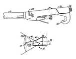
- FIG. 1is a perspective view of an endoscope emerging from a housing with an instrument support disposed thereon according to the present invention
- FIG. 2is a perspective view of the embodiment of FIG. 1 showing a surgical instrument supported on the instrument support;
- FIG. 3is a front view of a housing and clamp for the instrument of FIG. 1;
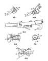
- FIG. 4is a perspective view of a tissue-dissecting tip of one configuration according to the present invention.
- FIG. 5is an end view of the tip according to FIG. 4.
- FIG. 6is a side sectional view of the tip of FIG. 4 .
- FIG. 1there is shown a perspective view of an elongated cannula 9 having a distal end (not shown) and a proximal end within housing 11 .
- One lumen within cannula 9extends between distal and proximal ends thereof and receives an endoscope 13 therein that facilitates the viewing of a surgical procedure at the distal end from the proximal end that extends from the housing 11 .
- the endoscope 13may include an eyepiece and an additional video detector 15 that attaches in axial alignment with the elongated optical axis of the endoscope 13 .
- the body of the endoscope 13 that extends from the housingincludes a lighting port 17 that may also be used conveniently, as later described herein, for rotationally orienting the endoscope 13 relative to the cannula 9 and housing 11 .
- an instrument bridge 19includes a base clamp 21 attached to a lateral extension 23 that includes a smaller clamp or groove 25 at the distal end of the extension 23 .
- the structure 21 , 23 , 25may be formed of a resilient polymeric material such as polycarbonate, or the like, to provide flexibility and resilient clamping force in the base clamp 21 when disposed about the generally cylindrical body of the endoscope 13 .
- the base clamp 21may include a partial circumferential ring in excess of ⁇ radians and of about the same internal diameter as the cylindrical body of the endoscope 13 to promote snap-on clamping about the body of the endoscope 13 .
- the internal diameter of the partial circumferential ringmay be selected to fit snugly about the body of the endoscope 13 , and to permit rotation of the instrument bridge 19 about the endoscope 13 as desired, for example, when rotating the cannula 9 about the endoscope 13 .
- an endoscopic surgical instrument 27such as bipolar scissors having a small cross section over its elongated length for slidably and flexibly extending within a lumen of the cannula 9 between the ends thereof may ‘fan’ out or angle away from the elongated axis of the cannula at the proximal end thereof to be supported on the instrument bridge 19 .
- the clamp or groove 25 in the outer end of the lateral extension 23 of the instrument bridge 19may firmly support the surgical instrument 27 therein, for example, via resilient clamping force about the cross section of the surgical instrument 27 .
- the groove 25may be formed in the resilient material of the instrument bridge 19 with smaller diameter than the diameter of the surgical instrument 27 , and with a substantially circular interior shape in excess of ⁇ radian circumference to promote snap clamping of the surgical instrument 27 in position, as shown.
- the circular interior shape of groove 25may be of about the same diameter as the diameter of the surgical instrument 27 where desired to promote rotational and sliding movement thereof within the groove 25 .
- an endoscope 13may include an optical-fiber lighting channel for delivering illuminating light flux to the distal end of the endoscope within the cannula 9 from a light source (not shown) that attaches to the lighting port 17 .
- This portis commonly rigidly affixed to the cylindrical body of the endoscope 13 , for example, to contain input ends for optical fibers that channel light to the distal end of the endoscope.
- the lighting port 17may be clamped into lateral position relative to housing 29 by a hook-shaped clamping block 31 that may be selectively removed and attached to the housing 29 via hollow threaded fastener 33 .
- This fastener 33thus permits a surgical instrument such as bipolar scissors to be slidably and rotationally positioned within the cannula 9 , and also facilitates selective attachment of the clamping block 31 to the housing 29 .
- the hook-shaped segment 35 of the clamping block 31(one on each side of the clamping block 31 to facilitate one aligned and one oppositely-aligned clamping positions of the lighting port 17 ) is formed sufficiently thin of flexible material such as polyethylene or other resilient polymeric material to be deflected or flexed out of clamping engagement with the lighting port 17 .
- the hook-shaped segment 35is resilient and substantially semicircular with preferably less than ⁇ radian angular extent of the internal circumference about the diameter of the lighting port 17 , as shown in FIG. 3 .
- an endoscope disposed within the cannula and having a lighting port 17 disposed in clamped position relative to the housing 29 by the clamping block 31may be conveniently twisted out of such clamped position without unscrewing the threaded fastener 33 by deflecting the resilient hook-shaped segment 35 out of locking engagement about the lighting port 17 .
- an endoscope within cannula 9may be rotationally re-positioned relative to the cannula and the surgical instruments assembled therein in shorter time than is normally required to unscrew the threaded fastener 33 to release the clamping block 31 disposed about lighting port 17 of the endoscope.
- the transparent tip 37for attachment to the distal end of a cannula 9 to facilitate a surgical procedure such as blunt tissue dissection at a remote surgical site in a patient's body.
- the transparent tip 37includes a rearward section 38 that is disposed to attach (e.g., via press-fit, or adhesive attachment, or the like) to the distal end of a cannula, and includes a substantially conical forward section 39 that aligns with an endoscope within the cannula.
- the forward section 39is displaced eccentrically from a cylindrical axis of the rearward section 38 to facilitate optical axial alignment with a field of view 41 of an endoscope 13 that is eccentrically oriented, as shown in the end view of FIG. 5, relative to an elongated central axis of a cannula attached to the rearward section 38 of the tip 37 .
- the tip 37includes a transition section 43 intermediate the forward section 39 and the rearward section 38 that includes tapering side walls in smooth transition between the conical walls of the forward section 39 and the circumferential side walls of the rearward section 38 , as illustrated in side sectional view of FIG. 6 .
- the forward section 39 , intermediate section 43 and rearward section 38 of the tip 37may be formed integrally and substantially symmetrically about a central vertical plane 45 , as shown in FIGS. 4 and 5.
- the optical axis of the forward conical section 39may thus be aligned with the field of view 41 of an endoscope disposed in eccentric orientation relative to the cylindrical axis of the rearward section 38 of the tip 37 , as illustrated in the end view of FIG. 5 .
- the transparent tip 37 attached to the distal end of a cannula 9protects an endoscope disposed therein from tissue and fluids and includes the transparent forward section of the tip 37 substantially optically aligned with the field of view of the endoscope.
- the cannulamay be rotated about the elongated axis of the endoscope during tissue dissection along anterior and posterior segments of a saphenous vein to facilitate more complete dissection of connective tissue from the vein.
- Such rotation of the cannula 9 about the endoscopemay be conveniently accomplished by manually supplying rotational torque to the housing 29 relative to the endoscope 13 sufficiently to deflect the hook-shaped segment 35 , as shown in FIG. 3, away from clamping engagement about the lighting port 17 of the endoscope 13 .
- another lumen 48 of the cannulamay be used to position therein a surgical instrument such as bipolar scissors 27 to facilitate excision and cauterization of lateral branch vessels encountered along the length of the saphenous vein.
- the transparent tip 37includes a blunt, slightly rounded distal end 47 of approximately 0.040′′ radius for bluntly dissecting tissue away from a saphenous vein and associated lateral branch vessels, and such tip may be formed of a bioinert, transparent material such as polycarbonate, glass, or the like, with conical walls of substantially uniform thickness in the forward section 39 .
- a bioinert, transparent materialsuch as polycarbonate, glass, or the like
- conical walls of substantially uniform thickness in the forward section 39Such conical shape in alignment with the optical axis of the endoscope reduces visual distortion in the field of view 41 .
- the forward section 39 and intermediate section 43may be formed in alternative configurations such as spoon shape or duck-bill shape or elliptical shape, or the like, to optimize the optical characteristics.
- the forward section 39may be color tinted, at least within the field of view 41 of an endoscope to promote enhanced visual contrast between walls of a saphenous vein, connective tissue and blood encountered at a remote surgical site within a patient. It has been discovered that such color tinting at least of the forward section 39 within the spectral color range between yellow and blue tints enhances such visual contrast, with blue tint providing more effective visual contrast.
- the apparatus of the present inventionpromotes versatile and sturdy configurations of surgical instruments assembled within a cannula for performing surgical procedures at remote sites in tissue within a patient.
- An eccentric configuration of a blunt tip attached to the distal end of the cannulaaligns with the optical axis of an endoscope that is positioned eccentrically therein to facilitate rotational manipulation of the cannula and attached tip about the endoscope.
- the tissue-penetrating distal tip of small diameter aligned with an endoscope in one lumensignificantly reduces the force required to dissect tissue away from the saphenous vein. Additionally, such tip of small diameter improves maneuverability around lateral branch vessels and along the saphenous vein in the lower leg within a thinner layer of subcutaneous fat.
- transition cone between sections 38 and 39transitions from these benefits of a small cone to the larger diameter of a two-lumen cannula without significantly diminishing the benefits of a small-diameter blunt dissection tip.
- Clamped fixation of the endoscope within a housing attached to the proximal end of the cannulamay be conveniently overridden by deflecting a flexible hook-shaped segment of the clamp disposed about a lighting port of the endoscope in response to rotational torque applied to the housing relative to the endoscope.
- Color tinting of the transparent, tissue-dissecting tipserves as a rigid lens that promotes enhanced visual contrasts between tissue types encountered at remote surgical sites within a cavity in tissue of a patient.
- Such color tinted tipreduces glare reflected back from tissue and fluids and filters wavelengths of light transmitted back through the endoscope.
- a video detector attached to the proximal end of an endoscopemay, with associated electronics of conventional design, provide further enhanced visual contrasts using ‘white balance’ electronic filtering to render the color tinting apparently clear while providing the desired visual contrasts and effects.
- a remote surgical sitemay be visualized through an endoscope as illuminated by color-tinted light supplied to the remote surgical site for similar benefits of enhanced contrasts between types of tissues encountered at the remote surgical site within a cavity in tissue of a patient.
Landscapes
- Health & Medical Sciences (AREA)
- Life Sciences & Earth Sciences (AREA)
- Surgery (AREA)
- Nuclear Medicine, Radiotherapy & Molecular Imaging (AREA)
- Molecular Biology (AREA)
- Veterinary Medicine (AREA)
- Pathology (AREA)
- Public Health (AREA)
- General Health & Medical Sciences (AREA)
- Engineering & Computer Science (AREA)
- Biomedical Technology (AREA)
- Heart & Thoracic Surgery (AREA)
- Medical Informatics (AREA)
- Animal Behavior & Ethology (AREA)
- Physics & Mathematics (AREA)
- Biophysics (AREA)
- Radiology & Medical Imaging (AREA)
- Optics & Photonics (AREA)
- Endoscopes (AREA)
Abstract
Description
Claims (1)
Priority Applications (1)
| Application Number | Priority Date | Filing Date | Title |
|---|---|---|---|
| US10/237,450US6814696B1 (en) | 2000-04-28 | 2002-09-06 | Surgical apparatus |
Applications Claiming Priority (2)
| Application Number | Priority Date | Filing Date | Title |
|---|---|---|---|
| US09/560,636US6471638B1 (en) | 2000-04-28 | 2000-04-28 | Surgical apparatus |
| US10/237,450US6814696B1 (en) | 2000-04-28 | 2002-09-06 | Surgical apparatus |
Related Parent Applications (1)
| Application Number | Title | Priority Date | Filing Date |
|---|---|---|---|
| US09/560,636ContinuationUS6471638B1 (en) | 2000-04-28 | 2000-04-28 | Surgical apparatus |
Publications (1)
| Publication Number | Publication Date |
|---|---|
| US6814696B1true US6814696B1 (en) | 2004-11-09 |
Family
ID=24238649
Family Applications (2)
| Application Number | Title | Priority Date | Filing Date |
|---|---|---|---|
| US09/560,636Expired - LifetimeUS6471638B1 (en) | 2000-04-28 | 2000-04-28 | Surgical apparatus |
| US10/237,450Expired - LifetimeUS6814696B1 (en) | 2000-04-28 | 2002-09-06 | Surgical apparatus |
Family Applications Before (1)
| Application Number | Title | Priority Date | Filing Date |
|---|---|---|---|
| US09/560,636Expired - LifetimeUS6471638B1 (en) | 2000-04-28 | 2000-04-28 | Surgical apparatus |
Country Status (1)
| Country | Link |
|---|---|
| US (2) | US6471638B1 (en) |
Cited By (16)
| Publication number | Priority date | Publication date | Assignee | Title |
|---|---|---|---|---|
| US20030070683A1 (en)* | 2000-03-04 | 2003-04-17 | Deem Mark E. | Methods and devices for use in performing pulmonary procedures |
| US20060024638A1 (en)* | 2004-07-02 | 2006-02-02 | Kenneth Rosenblood | Curing light |
| US20100312053A1 (en)* | 2006-04-13 | 2010-12-09 | Larsen Dane M | Resectoscopic device and method |
| US7867163B2 (en) | 1998-06-22 | 2011-01-11 | Maquet Cardiovascular Llc | Instrument and method for remotely manipulating a tissue structure |
| US7938842B1 (en) | 1998-08-12 | 2011-05-10 | Maquet Cardiovascular Llc | Tissue dissector apparatus |
| US7972265B1 (en) | 1998-06-22 | 2011-07-05 | Maquet Cardiovascular, Llc | Device and method for remote vessel ligation |
| US7981133B2 (en) | 1995-07-13 | 2011-07-19 | Maquet Cardiovascular, Llc | Tissue dissection method |
| US8241210B2 (en) | 1998-06-22 | 2012-08-14 | Maquet Cardiovascular Llc | Vessel retractor |
| US8357139B2 (en) | 2000-03-04 | 2013-01-22 | Pulmonx Corporation | Methods and devices for use in performing pulmonary procedures |
| US9498246B2 (en) | 2013-03-14 | 2016-11-22 | Saphena Medical, Inc. | Unitary endoscopic vessel harvesting devices |
| US9814481B2 (en) | 2013-03-14 | 2017-11-14 | Saphena Medical, Inc. | Unitary endoscopic vessel harvesting devices |
| US9943328B2 (en) | 2015-04-28 | 2018-04-17 | Saphena Medical, Inc. | Unitary endoscopic vessel harvesting devices with an elastic force |
| US10299770B2 (en) | 2006-06-01 | 2019-05-28 | Maquet Cardiovascular Llc | Endoscopic vessel harvesting system components |
| US10363056B2 (en) | 2015-06-17 | 2019-07-30 | Saphena Medical, Inc. | Unitary endoscopic vessel harvesting devices |
| US10507012B2 (en) | 2000-11-17 | 2019-12-17 | Maquet Cardiovascular Llc | Vein harvesting system and method |
| US12357285B2 (en) | 2019-04-05 | 2025-07-15 | Saphena Medical, Inc. | Unitary device for vessel harvesting and method of using same |
Families Citing this family (31)
| Publication number | Priority date | Publication date | Assignee | Title |
|---|---|---|---|---|
| CA2642135C (en)* | 2001-11-21 | 2013-04-09 | E-Z-Em, Inc. | Device, system, kit or method for collecting effluent from an individual |
| US6830545B2 (en) | 2002-05-13 | 2004-12-14 | Everest Vit | Tube gripper integral with controller for endoscope of borescope |
| US7223230B2 (en)* | 2002-09-06 | 2007-05-29 | C. R. Bard, Inc. | External endoscopic accessory control system |
| US7070586B2 (en)* | 2003-01-17 | 2006-07-04 | Applied Medical Resources Corporation | Surgical access apparatus and method |
| US7854724B2 (en) | 2003-04-08 | 2010-12-21 | Surgiquest, Inc. | Trocar assembly with pneumatic sealing |
| US20050149094A1 (en)* | 2003-10-31 | 2005-07-07 | Olympus Corporation | Trocar |
| US7662164B2 (en)* | 2003-10-31 | 2010-02-16 | Olympus Corporation | Living-body tissue removing apparatus |
| US8105231B2 (en)* | 2003-10-31 | 2012-01-31 | Olympus Corporation | Living-body tissue removing apparatus |
| WO2005105198A1 (en)* | 2004-04-23 | 2005-11-10 | E-Z-Em, Inc. | Manually operated insufflator |
| US7887558B2 (en) | 2004-09-28 | 2011-02-15 | Maquet Cardiovascular Llc | Modular vessel harvesting system and method |
| WO2006069231A2 (en)* | 2004-12-22 | 2006-06-29 | E-Z-Em, Inc. | System, imaging suite, and method for using an electro-pneumatic insufflator for magnetic resonance imaging |
| US7806850B2 (en) | 2005-10-24 | 2010-10-05 | Bracco Diagnostics Inc. | Insufflating system, method, and computer program product for controlling the supply of a distending media to an endoscopic device |
| WO2008045316A2 (en)* | 2006-10-06 | 2008-04-17 | Surgiquest, Incorporated | Visualization trocar |
| USD667954S1 (en) | 2007-10-05 | 2012-09-25 | Surgiquest, Inc. | Visualization trocar |
| USD663838S1 (en) | 2007-10-05 | 2012-07-17 | Surgiquest, Inc. | Visualization trocar |
| EP2209416A4 (en) | 2007-10-15 | 2014-05-14 | Univ Maryland | APPARATUS AND METHOD FOR ANALYZING THE INTESTINES OF A PATIENT |
| US8048100B2 (en)* | 2008-06-10 | 2011-11-01 | Terumo Cardiovascular Systems, Corp. | Blunt dissector for separating blood vessels from surrounding tissue |
| JP5733831B2 (en) | 2008-10-10 | 2015-06-10 | サージクェスト,インコーポレーテッド | System and method for improved gas recirculation in a surgical trocar with a gas sealing mechanism |
| US8657818B2 (en)* | 2009-08-21 | 2014-02-25 | Maquet Cardiovascular Llc | Single handled endoscopic vessel harvesting system with rotation control |
| US9700659B2 (en) | 2009-11-09 | 2017-07-11 | Viaderm Llc | Cardiac assist device, instruments, and methods |
| US9561335B2 (en) | 2010-11-24 | 2017-02-07 | Bracco Diagnostics Inc. | System, device, and method for providing and controlling the supply of a distending media for CT colonography |
| WO2012122263A2 (en) | 2011-03-08 | 2012-09-13 | Surgiquest, Inc. | Trocar assembly with pneumatic sealing |
| US9186173B2 (en)* | 2012-04-27 | 2015-11-17 | Specialty Care, Inc. | Optical obturator system |
| BR112015022987A2 (en)* | 2013-03-15 | 2017-07-18 | Olive Medical Corp | integrated prism trocar visualization for use with angled endoscope |
| US11033182B2 (en) | 2014-02-21 | 2021-06-15 | 3Dintegrated Aps | Set comprising a surgical instrument |
| US11020144B2 (en) | 2015-07-21 | 2021-06-01 | 3Dintegrated Aps | Minimally invasive surgery system |
| CN108024806B (en) | 2015-07-21 | 2022-07-01 | 3D集成公司 | Cannula assembly kit, trocar assembly kit, sleeve assembly, minimally invasive surgical system and method thereof |
| DK178899B1 (en) | 2015-10-09 | 2017-05-08 | 3Dintegrated Aps | A depiction system |
| US11172982B2 (en) | 2018-07-03 | 2021-11-16 | Terumo Cardiovascular Systems Corporation | Integrated grounding electrodes for electrocautery vessel harvester |
| EP3831291B1 (en)* | 2019-12-05 | 2025-02-19 | Erbe Elektromedizin GmbH | Electrosurgical treatment instrument |
| EP4598347A1 (en) | 2022-10-04 | 2025-08-13 | Marizyme, Inc. | Kits and use thereof in surgical procedures for endoscopic harvesting of vessels |
Citations (19)
| Publication number | Priority date | Publication date | Assignee | Title |
|---|---|---|---|---|
| US1933787A (en) | 1930-03-05 | 1933-11-07 | Eastman Kodak Co | Method and apparatus for making color motion pictures |
| US3224320A (en) | 1959-05-05 | 1965-12-21 | Slagteriernes Forskningsinst | Apparatus for determination of the distribution of meat and fat in slaughtered animals or parts thereof |
| US3437747A (en) | 1964-03-24 | 1969-04-08 | Sheldon Edward E | Devices for inspection using fiberoptic members |
| US3556085A (en) | 1968-02-26 | 1971-01-19 | Olympus Optical Co | Optical viewing instrument |
| US4319563A (en) | 1977-12-02 | 1982-03-16 | Olympus Optical Co., Ltd. | Endoscope with a smoothly curved distal end face |
| US4630598A (en) | 1984-05-29 | 1986-12-23 | Richard Wolf Gmbh | Uretero-renoscope |
| EP0347140A1 (en) | 1988-06-13 | 1989-12-20 | MacAnally, Richard B. | Dual view endoscope |
| EP0369937A1 (en) | 1988-11-18 | 1990-05-23 | Effner Biomet GmbH | Endoscope, in particular an arthroscope |
| US5159920A (en) | 1990-06-18 | 1992-11-03 | Mentor Corporation | Scope and stent system |
| US5163949A (en) | 1990-03-02 | 1992-11-17 | Bonutti Peter M | Fluid operated retractors |
| US5271380A (en) | 1990-11-06 | 1993-12-21 | Siegfried Riek | Penetration instrument |
| US5334150A (en) | 1992-11-17 | 1994-08-02 | Kaali Steven G | Visually directed trocar for laparoscopic surgical procedures and method of using same |
| US5385572A (en) | 1992-11-12 | 1995-01-31 | Beowulf Holdings | Trocar for endoscopic surgery |
| EP0642764A1 (en) | 1993-09-13 | 1995-03-15 | United States Surgical Corporation | Optical Trocar |
| US5591192A (en) | 1995-02-01 | 1997-01-07 | Ethicon Endo-Surgery, Inc. | Surgical penetration instrument including an imaging element |
| US5722934A (en)* | 1995-10-20 | 1998-03-03 | Ethicon Endo-Surgery, Inc. | Method and devices for endoscopoic vessel harvesting |
| US5738628A (en) | 1995-03-24 | 1998-04-14 | Ethicon Endo-Surgery, Inc. | Surgical dissector and method for its use |
| US5980549A (en) | 1995-07-13 | 1999-11-09 | Origin Medsystems, Inc. | Tissue separation cannula with dissection probe and method |
| US6221007B1 (en) | 1996-05-03 | 2001-04-24 | Philip S. Green | System and method for endoscopic imaging and endosurgery |
- 2000
- 2000-04-28USUS09/560,636patent/US6471638B1/ennot_activeExpired - Lifetime
- 2002
- 2002-09-06USUS10/237,450patent/US6814696B1/ennot_activeExpired - Lifetime
Patent Citations (19)
| Publication number | Priority date | Publication date | Assignee | Title |
|---|---|---|---|---|
| US1933787A (en) | 1930-03-05 | 1933-11-07 | Eastman Kodak Co | Method and apparatus for making color motion pictures |
| US3224320A (en) | 1959-05-05 | 1965-12-21 | Slagteriernes Forskningsinst | Apparatus for determination of the distribution of meat and fat in slaughtered animals or parts thereof |
| US3437747A (en) | 1964-03-24 | 1969-04-08 | Sheldon Edward E | Devices for inspection using fiberoptic members |
| US3556085A (en) | 1968-02-26 | 1971-01-19 | Olympus Optical Co | Optical viewing instrument |
| US4319563A (en) | 1977-12-02 | 1982-03-16 | Olympus Optical Co., Ltd. | Endoscope with a smoothly curved distal end face |
| US4630598A (en) | 1984-05-29 | 1986-12-23 | Richard Wolf Gmbh | Uretero-renoscope |
| EP0347140A1 (en) | 1988-06-13 | 1989-12-20 | MacAnally, Richard B. | Dual view endoscope |
| EP0369937A1 (en) | 1988-11-18 | 1990-05-23 | Effner Biomet GmbH | Endoscope, in particular an arthroscope |
| US5163949A (en) | 1990-03-02 | 1992-11-17 | Bonutti Peter M | Fluid operated retractors |
| US5159920A (en) | 1990-06-18 | 1992-11-03 | Mentor Corporation | Scope and stent system |
| US5271380A (en) | 1990-11-06 | 1993-12-21 | Siegfried Riek | Penetration instrument |
| US5385572A (en) | 1992-11-12 | 1995-01-31 | Beowulf Holdings | Trocar for endoscopic surgery |
| US5334150A (en) | 1992-11-17 | 1994-08-02 | Kaali Steven G | Visually directed trocar for laparoscopic surgical procedures and method of using same |
| EP0642764A1 (en) | 1993-09-13 | 1995-03-15 | United States Surgical Corporation | Optical Trocar |
| US5591192A (en) | 1995-02-01 | 1997-01-07 | Ethicon Endo-Surgery, Inc. | Surgical penetration instrument including an imaging element |
| US5738628A (en) | 1995-03-24 | 1998-04-14 | Ethicon Endo-Surgery, Inc. | Surgical dissector and method for its use |
| US5980549A (en) | 1995-07-13 | 1999-11-09 | Origin Medsystems, Inc. | Tissue separation cannula with dissection probe and method |
| US5722934A (en)* | 1995-10-20 | 1998-03-03 | Ethicon Endo-Surgery, Inc. | Method and devices for endoscopoic vessel harvesting |
| US6221007B1 (en) | 1996-05-03 | 2001-04-24 | Philip S. Green | System and method for endoscopic imaging and endosurgery |
Cited By (29)
| Publication number | Priority date | Publication date | Assignee | Title |
|---|---|---|---|---|
| US7981133B2 (en) | 1995-07-13 | 2011-07-19 | Maquet Cardiovascular, Llc | Tissue dissection method |
| US7867163B2 (en) | 1998-06-22 | 2011-01-11 | Maquet Cardiovascular Llc | Instrument and method for remotely manipulating a tissue structure |
| US7972265B1 (en) | 1998-06-22 | 2011-07-05 | Maquet Cardiovascular, Llc | Device and method for remote vessel ligation |
| US8241210B2 (en) | 1998-06-22 | 2012-08-14 | Maquet Cardiovascular Llc | Vessel retractor |
| US9730782B2 (en) | 1998-08-12 | 2017-08-15 | Maquet Cardiovascular Llc | Vessel harvester |
| US9700398B2 (en) | 1998-08-12 | 2017-07-11 | Maquet Cardiovascular Llc | Vessel harvester |
| US8986335B2 (en) | 1998-08-12 | 2015-03-24 | Maquet Cardiovascular Llc | Tissue dissector apparatus and method |
| US8460331B2 (en) | 1998-08-12 | 2013-06-11 | Maquet Cardiovascular, Llc | Tissue dissector apparatus and method |
| US7938842B1 (en) | 1998-08-12 | 2011-05-10 | Maquet Cardiovascular Llc | Tissue dissector apparatus |
| US8357139B2 (en) | 2000-03-04 | 2013-01-22 | Pulmonx Corporation | Methods and devices for use in performing pulmonary procedures |
| US20030070683A1 (en)* | 2000-03-04 | 2003-04-17 | Deem Mark E. | Methods and devices for use in performing pulmonary procedures |
| US10507012B2 (en) | 2000-11-17 | 2019-12-17 | Maquet Cardiovascular Llc | Vein harvesting system and method |
| US20060024638A1 (en)* | 2004-07-02 | 2006-02-02 | Kenneth Rosenblood | Curing light |
| US20080057463A1 (en)* | 2004-07-02 | 2008-03-06 | Discus Dental, Llc | Curing Light Having a Detachable Tip |
| US7273369B2 (en) | 2004-07-02 | 2007-09-25 | Discus Dental, Llc | Curing light |
| US20060044823A1 (en)* | 2004-07-02 | 2006-03-02 | Discus Dental Impressions, Inc. | Curing light having a detachable tip |
| US20100312053A1 (en)* | 2006-04-13 | 2010-12-09 | Larsen Dane M | Resectoscopic device and method |
| US11134835B2 (en) | 2006-06-01 | 2021-10-05 | Maquet Cardiovascular Llc | Endoscopic vessel harvesting system components |
| US10299770B2 (en) | 2006-06-01 | 2019-05-28 | Maquet Cardiovascular Llc | Endoscopic vessel harvesting system components |
| US11141055B2 (en) | 2006-06-01 | 2021-10-12 | Maquet Cardiovascular Llc | Endoscopic vessel harvesting system components |
| US9814481B2 (en) | 2013-03-14 | 2017-11-14 | Saphena Medical, Inc. | Unitary endoscopic vessel harvesting devices |
| US10537353B2 (en) | 2013-03-14 | 2020-01-21 | Saphena Medical, Inc. | Unitary endoscopic vessel harvesting devices |
| US9498246B2 (en) | 2013-03-14 | 2016-11-22 | Saphena Medical, Inc. | Unitary endoscopic vessel harvesting devices |
| US11751896B2 (en) | 2013-03-14 | 2023-09-12 | Saphena Medical, Inc. | Unitary endoscopic vessel harvesting devices |
| US12064134B2 (en) | 2013-03-14 | 2024-08-20 | Saphena Medical, Inc. | Unitary endoscopic vessel harvesting devices |
| US9943328B2 (en) | 2015-04-28 | 2018-04-17 | Saphena Medical, Inc. | Unitary endoscopic vessel harvesting devices with an elastic force |
| US10363056B2 (en) | 2015-06-17 | 2019-07-30 | Saphena Medical, Inc. | Unitary endoscopic vessel harvesting devices |
| US10874415B2 (en) | 2015-06-17 | 2020-12-29 | Saphena Medical, Inc. | Unitary endoscopic vessel harvesting devices |
| US12357285B2 (en) | 2019-04-05 | 2025-07-15 | Saphena Medical, Inc. | Unitary device for vessel harvesting and method of using same |
Also Published As
| Publication number | Publication date |
|---|---|
| US6471638B1 (en) | 2002-10-29 |
Similar Documents
| Publication | Publication Date | Title |
|---|---|---|
| US6814696B1 (en) | Surgical apparatus | |
| US4736733A (en) | Endoscope with removable eyepiece | |
| US5957832A (en) | Stereoscopic percutaneous visualization system | |
| US5152278A (en) | Surgical endoscope apparatus | |
| US5271380A (en) | Penetration instrument | |
| EP3313310B1 (en) | Devices for assisting in open surgeries | |
| EP2782491B1 (en) | Endoscopic system for optimized visualization | |
| CA2141019C (en) | Instrument for the penetration of body tissue | |
| US8317815B2 (en) | Visualization trocar | |
| US6277064B1 (en) | Surgical instrument with rotatably mounted offset endoscope | |
| AU2007338691B2 (en) | Surgical visual obturator | |
| US6761684B1 (en) | Endoscope tip protection system | |
| AU2007267794B2 (en) | Illuminated surgical access system including a surgical access device and integrated light emitter | |
| EP0723416A1 (en) | Stereoscopic percutaneous visualization system | |
| US5209219A (en) | Endoscope adaptor | |
| US20180042772A1 (en) | Variable-gauge microsurgical instruments for use in ophthalmic or vitreoretinal surgery | |
| US20090221991A1 (en) | Multi-Purpose Surgical Instrument With Removable Component | |
| EP0973453A2 (en) | Surgical instrument assembly for use in endoscopic surgery | |
| CA2099578A1 (en) | Laser delivery system | |
| US20150351615A1 (en) | Surgical adapter assembly for use with endoscope | |
| US20090030406A1 (en) | Variable intensity endoilluminator | |
| US20040249424A1 (en) | Endoilluminator | |
| US20040017626A1 (en) | Telescopic mirror attachment for medical, surgical, and dental instruments | |
| WO1995020341A1 (en) | Endoscope with insertable tool | |
| CN111297313B (en) | Human body insertion assembly and nasal endoscope |
Legal Events
| Date | Code | Title | Description |
|---|---|---|---|
| STCF | Information on status: patent grant | Free format text:PATENTED CASE | |
| FPAY | Fee payment | Year of fee payment:4 | |
| AS | Assignment | Owner name:MAQUET CARDIOVASCULAR LLC, CALIFORNIA Free format text:ASSIGNMENT OF ASSIGNORS INTEREST;ASSIGNORS:BOSTON SCIENTIFIC LIMITED;BOSTON SCIENTIFIC SCIMED, INC.;CORVITA CORPORATION;AND OTHERS;REEL/FRAME:020462/0322 Effective date:20080102 Owner name:MAQUET CARDIOVASCULAR LLC,CALIFORNIA Free format text:ASSIGNMENT OF ASSIGNORS INTEREST;ASSIGNORS:BOSTON SCIENTIFIC LIMITED;BOSTON SCIENTIFIC SCIMED, INC.;CORVITA CORPORATION;AND OTHERS;REEL/FRAME:020462/0322 Effective date:20080102 | |
| FPAY | Fee payment | Year of fee payment:8 | |
| AS | Assignment | Owner name:ORIGIN MEDSYSTEMS, LLC, CALIFORNIA Free format text:CHANGE OF NAME;ASSIGNOR:ORIGIN MEDSYSTEMS, INC.;REEL/FRAME:033004/0174 Effective date:20080103 | |
| AS | Assignment | Owner name:MAQUET CARDIOVASCULAR LLC, NEW JERSEY Free format text:ASSIGNMENT OF ASSIGNORS INTEREST;ASSIGNOR:ORIGIN MEDSYSTEMS, LLC;REEL/FRAME:033022/0425 Effective date:20140523 | |
| FPAY | Fee payment | Year of fee payment:12 |