US6814575B2 - Manufacturing a dental implant drill guide and a dental implant superstructure - Google Patents
Manufacturing a dental implant drill guide and a dental implant superstructureDownload PDFInfo
- Publication number
- US6814575B2 US6814575B2US10/086,893US8689302AUS6814575B2US 6814575 B2US6814575 B2US 6814575B2US 8689302 AUS8689302 AUS 8689302AUS 6814575 B2US6814575 B2US 6814575B2
- Authority
- US
- United States
- Prior art keywords
- implant
- drill
- jawbone
- dental
- guide
- Prior art date
- Legal status (The legal status is an assumption and is not a legal conclusion. Google has not performed a legal analysis and makes no representation as to the accuracy of the status listed.)
- Expired - Lifetime, expires
Links
Images


Classifications
- A—HUMAN NECESSITIES
- A61—MEDICAL OR VETERINARY SCIENCE; HYGIENE
- A61C—DENTISTRY; APPARATUS OR METHODS FOR ORAL OR DENTAL HYGIENE
- A61C1/00—Dental machines for boring or cutting ; General features of dental machines or apparatus, e.g. hand-piece design
- A61C1/08—Machine parts specially adapted for dentistry
- A61C1/082—Positioning or guiding, e.g. of drills
- A61C1/084—Positioning or guiding, e.g. of drills of implanting tools
- A—HUMAN NECESSITIES
- A61—MEDICAL OR VETERINARY SCIENCE; HYGIENE
- A61C—DENTISTRY; APPARATUS OR METHODS FOR ORAL OR DENTAL HYGIENE
- A61C9/00—Impression cups, i.e. impression trays; Impression methods
- A61C9/004—Means or methods for taking digitized impressions
- A61C9/0046—Data acquisition means or methods
- G—PHYSICS
- G16—INFORMATION AND COMMUNICATION TECHNOLOGY [ICT] SPECIALLY ADAPTED FOR SPECIFIC APPLICATION FIELDS
- G16H—HEALTHCARE INFORMATICS, i.e. INFORMATION AND COMMUNICATION TECHNOLOGY [ICT] SPECIALLY ADAPTED FOR THE HANDLING OR PROCESSING OF MEDICAL OR HEALTHCARE DATA
- G16H20/00—ICT specially adapted for therapies or health-improving plans, e.g. for handling prescriptions, for steering therapy or for monitoring patient compliance
- G16H20/40—ICT specially adapted for therapies or health-improving plans, e.g. for handling prescriptions, for steering therapy or for monitoring patient compliance relating to mechanical, radiation or invasive therapies, e.g. surgery, laser therapy, dialysis or acupuncture
Definitions
- the present inventionrelates to a method of manufacturing a dental implant drill guide.
- the inventionalso relates to a method for the reconstruction of an edentulous jawbone.
- the oral surgeontypically has difficulty deciding on a drill axis for the implants since the ideal position for the implants should be decided with knowledge of the jawbone structure into which the implant is to be inserted, knowledge of the position within the jawbone structure of the nerve tissue, the gum surface and the required position and dimensions of the false teeth or dentures to be supported by the dental implant.
- the dentist or dental surgeonsimply makes a best guess in light of his knowledge of the patient.
- the imperfectionsmay be lack of ideal support, unfavorable angulation of an implant causing a weakness in the implant which may cause failure over time, or a visually perceptible defect in the appearance of the prosthesis.
- a method of manufacturing a dental implant drill guidecomprising the steps of: imaging a jawbone and tissue structure with a reference to a known anatomical reference to produce a three-dimensional computer graphics model; selecting at least one implant drill hole position for at least one dental implant using said model, said position being specified in three dimensions, including a hole termination point and orientation, and being referenced to said anatomical reference, entering at least one set of implant drill hole position coordinates into a computer controlled precision manufacturing device; providing a drill template body having a first surface adapted to overlie a gum surface of the jawbone in a single predetermined position; using said precision manufacturing device to provide a fixed orientation drill guide socket in said template body for each one of said at least one drill hole position with a corresponding position and orientation.
- a method for allowing the reconstruction of an edentulous jawbone in a single surgical operationcomprising the steps of: a) creating a three-dimensional graphic computer model of a patient's gum, jawbone and tissue structure, and of a dental prosthesis to be placed over the gum; b) selecting a number of virtual implant drill holes positions for corresponding implants using said model; c) entering data related to the virtual implant drill hole positions into a computer controlled precision manufacturing device; d) providing a rigid drill template body; e) using said precision manufacturing device to provide a fixed orientation socket in said drill template body for each one of said implant drill hole positions selected in step b); f) prior to the surgical operation, using said data on said virtual implant drill hole positions and said precision manufacturing device to make a dental implant superstructure having a number of dental implant abutting flanges interconnected by a bridge in a fixed configuration in which said dental abutting flanges are positioned in accordance with the virtual implant drill hole
- the patientis typically edentured, namely, the patient has had all teeth pulled from the jawbone, and the jawbone has been given time to heal since the teeth were pulled. If the patient decides to proceed with dental implants and the placement of a superstructure for solidly securing dentures over the gum, a period of about 1 month is provided for from the time of pulling any remaining teeth from the jawbone before proceeding with the operation of inserting implants into the jawbone.
- a medical image of the jawbone and tissue structureis obtained by using x-ray imaging, MRI or possibly nuclear imaging techniques to produce a three-dimensional computer graphics model which has a reference to the gum surface or some other fixed reference with respect to the patient's jawbone.
- a radiographic scanner guideis used which is molded to conform to the shape of the patient's gums and which includes radio-opaque spheres whose positions with respect to the gum surface is known.
- the primary advantage of the inventionis that the oral surgeon may select the optimum position for dental implants using the three-dimensional computer graphics model of the jawbone and tissue structure. Selection of the drill hole positions using the computer graphics model is transferred to a CNC device for the purposes of providing fixed drill guide sockets in the template body for each one of the drill hole positions or position selected using the computer graphics model. While the model is three-dimensional, it may be convenient for the purposes of selecting the drill hole axis to use a two-dimensional representation of the jawbone and tissue structure, the two-dimensional view being displayed with a user controlled slice angle.
- the dental surgeonwill select the position for each implant drill hole, not only to position the implant in the optimum location within the jawbone, but also to result in a position of support which is suitable for supporting the dentures.
- the patient's denturesin the proper spatial relationship with respect to the jawbone and tissue structure. This requires imaging the patient's dentures or teeth, and possibly gum structure, in addition to the jawbone and tissue structure, in such a way that all images are referenced with respect to one another to be integrated into the same three-dimensional computer graphics model.
- the drill template bodyis preferably molded on a physical model of the gum surface into which model the CNC device has previously drilled the desired implant drill holes.
- the drill holes in the physical modelare used to build a mold for the drill guide sockets. This prevents the need to use the CNC device to produce fine details except for the precision drilling of the drill holes.
- Imaging of the dentures or teeth to be placed over the gum surface and the imaging of the gum surfacecan be carried out by using laser camera imaging techniques known in the art. These images are preferably obtained using a physical model of the patient's gum surface, and the physical model is imaged in such a way that the images can be referenced accurately to the jawbone and tissue structure images.
- the actual dental implant position datais obtained by taking an imprint using transfers connected to the implants.
- the imprintis taken using the same drill guide with the sockets of the drill guide being large enough to receive the transfers and surrounding imprint material.
- the positions and orientations of the transfersare physically measured along with a reference to the drill guide which will permit the relative positions of the implants to be known with a reference to a standard frame of reference.
- the standard frame of referenceit is possible to generate a computer graphics model of the gum surface, dentures or teeth and dental implants which allows the dental surgeon or technician to select the best shape for the overlying bridge of the superstructure.
- the implant drill hole positions selected using the computer graphics modelcan also be used to make the superstructure.
- the superstructurecan be made prior to the surgical operation, i.e. prior to the insertion of the implants into the patient's jawbone. This advantageously provides for the installation of the implants and the superstructure in a single surgical operation.
- This novel approach of creating a superstructure on the basis of the virtual positions of the dental implants selected using the three-dimensional computer graphic model of the jawbone and the dental prosthesishas the following advantages for the surgeon:
- the ideal form of the superstructurecan be automatically designed using the computer model taking into consideration the form of the laser camera imaged teeth and by subtracting a thickness of porcelain which the technician requires to recreate the shape of the imaged teeth.
- the shape of the superstructurecan be automatically determined by taking into account the external shape of the prosthesis and by circulating the superstructure inside the prosthesis, making sure that the necessary thickness of prosthesis material (e.g. acrylic) will be available all around in order to provide a adequately strong prosthesis.
- the entire superstructureis cut using a CNC milling machine programmed to cut according to the shape data specified using the computer model.
- FIG. 1is a perspective view of an articulator supporting a physical model of a patient's upper and lower gums with dentures in place;
- FIG. 2is a perspective view similar to FIG. 1 in which the dentures have been replaced by a radiographic scanning guide;
- FIG. 3is a perspective view of the radiographic scanning guide
- FIG. 4is a perspective view of a three-dimensional computer model of a patient's lower jawbone shown partly broken away with the radio-opaque reference spheres and reference coordinate superimposed;
- FIG. 5is a flow diagram of the method of manufacturing the dental implant drill guide according to the preferred embodiment
- FIG. 6is a panoramic view of a lower jawbone of a patient with the gum line and dentures superimposed;
- FIG. 7is a cross-sectional view about line 7 of FIG. 6;
- FIG. 8is a block diagram of the CNC drill device and data entry terminal
- FIG. 9is a perspective view of a five axis CNC drill device
- FIG. 10is a front view of a physical model with four drill axes shown
- FIG. 11is a view similar to FIG. 10 in which a drill guide has been molded with the fixed drill sockets formed by pins inserted in the drill holes;
- FIG. 12is a perspective view of the drill guide according to the preferred embodiment.
- FIG. 13is a sectional view of the drill guide being used to drill a patient's jawbone
- FIG. 14is an enlarged sectional view of a jawbone having received an implant with the drill guide placed on top of the gum surface to act as an impression tray for the purposes of taking an exact imprint of the implant position using a transfer;
- FIG. 15is a sectional view of a computer model illustrating the denture fit over the patient's gums with the implant head in correct relative position;
- FIG. 16illustrates a similar computer graphics image as in FIG. 15 for a position between two implants
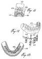
- FIG. 17illustrates a perspective view of lower dentures and a lower superstructure
- FIG. 18is a view from underneath the assembled components illustrated in FIG. 17 .
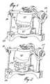
- an articulator 20as is known in the art is set up to support a lower physical model 21 and an upper physical model 22 of a patient's mouth with lower and upper dentures 23 and 24 supported by the physical model with the teeth of the dentures in proper alignment.
- the articulatoris adjusted using the adjustment means 25 and 26 as is known in the art.
- the dentures 23 and 24are removed and a scanner guide 27 is made by hand to fit exactly the space occupied by the upper and lower denture.
- Radio-opaque reference spheres 28having a known diameter are bonded to the guide 27 with one sphere on each side at the rear and one in the front.
- the spheresare shown near the lower jaw surface since it is the lower jaw that is to be imaged.
- the spherescould likewise be placed near the upper jaw surface as the case may be.
- the separated scanner guide body 27is illustrated in FIG. 3 .
- the particular advantage of the scanner guide 27 according to the present inventionis that during radiographic scanning of the patient's jaw, the patient may comfortably hold the scanner guide 27 in place by closing down on the same.
- the lower jawcould move during imaging and must be secured by means such as the scanner guide 27 .
- the patient's headis held in place during radiographic scanning using a suitable brace as is known in the art.
- the result of the radiographic scanningis to obtain a three-dimensional computer graphics model 29 of the patient's lower jaw. Images of the reference spheres 28 appear as 33 and provide a reference to a coordinate axes 32 .
- the dental surgeonis capable of viewing with the model 29 the nerve 37 which extends from the base of the jaw until it exits the jawbone at each side of the chin.
- a drill axis 31 for each proposed drill hole 34is selected on the computer model. The end point of the drill hole 36 is also selected.
- a first angle ⁇may define an angle of the drill axis 31 with respect to the x-z plane and a second angular parameter ⁇ may define the angle between the drill axis 31 in the z-y plane.
- selection of the drill axes 31 for the drill holes 34is done with knowledge of the relative position of the gum surface and the relative position of the dentures or teeth.
- the 3-D computer model 29is built up using the radiographic 3-D imaging data as well as referenced gum surface image data and referenced denture image data.
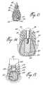
- FIG. 6there is shown a panoramic slice view of the 3-D model 29 showing the gum surface 44 and dentures 43 superposed the cortical bone structure 41 and the marrow 42 .
- FIG. 7it is possible to view for a selected drill axis 31 the resulting implant position 49 and how this relates to the bone structure 41 and 42 , the nerve 37 , if present, as well as the lower and upper denture structure 44 and 43 .
- the dental surgeonis able to select the optimum depth, position and angular orientation for the implant 49 relying entirely on the computer model.
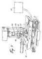
- the CNC drill 52has a drill bit 53 which is capable of moving and drilling along a first vertical direction 54 .
- the physical model 21is mounted in such a way that it is able to turn about two directions 55 and 56 on a platform which is able to move in directions 57 and 60 .
- the CNC drill 52is capable of moving about five axes.
- the scanner guidemay be placed on top of the physical model 21 and a coordinates measuring machine (CMM) connected to CNC drill 52 is used to accurately locate the position of each one of the position reference spheres and reference these to the CNC drill's reference frame.
- CCMMcoordinates measuring machine
- the CNC drill 52is then programmed to convert the hole position and orientation data as referenced to the frame of reference of the computer model to the reference frame of the CNC drill so that the drill holes may be prepared in the physical model 21 .
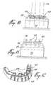
- drill holes 58are cut into the physical model 21 which is mounted on a base 59 .
- the drill hole axes 31 as shownare in different positions and orientations.
- rods 62are inserted into the holes 58 .
- the socket forming mold parts 63are placed over the rods 62 and a surrounding mold structure (not shown) is placed around the physical model 21 to allow for the molded guide body 61 to be formed. Since the holes 58 are of different heights, the socket forming mold parts 63 are adjusted in size such that the distance between the circular flange edge and the end of the rods 102 is a constant. In this way, the circular flange edge 64 of the drill guide sockets is at a fixed distance with respect to the desired end point of the drill hole.
- the finished molded drill guide body 61has a plurality of drill guide tubes 66 inserted into the drill guide sockets 68 , and three holes 67 are additionally provided for transitionally securing the drill guide 61 to the patient's jawbone during surgery.
- the drill guide tubes 66may be removed and reinserted into the drill guide sockets 68 in order to change the internal diameter of the drill guide tubes as is required during surgery since the implant drill hole is started with a very small diameter drill bit and subsequently larger drill bits are used until the full size implant drill hole is obtained. As shown in FIG.
- the drill used in surgeryis provided with a collar 69 for abutting against the upper surface of the guide tube 66 in such a way that the distance between the bottom of the collar 69 and the end of the drill bit 71 is fixed as required.
- the collar 69is integral with the drill bit 71 .
- the oral surgeonprepares the implant holes using the drill guide 61 by removing circular portions of the gum (gingival taps) at the implant sites.
- a procedure known as “flap surgery”is carried out in which a piece of the gum covering the jawbone where the implant hole is to be drilled is cut and peeled back so that the oral surgeon has clear access to the jawbone surface.
- the surgeonhas the option of doing flap surgery if required or circumferential surgery as needed of course, if a conventional flap surgery is to be done, a modification of the surgical guide should be done, i.e. the guide should be removable as needed for flap surgery. In order to put the guide back at the same location, the use of transitional implants is needed to seat the guide after the flap is done. If the circular approach is chosen, there is no need to remove the guide during surgery, and by avoiding flap surgery, post operation healing time should be reduced.
- the oral surgeonscrews in an implant 72 into the hole made using drill guide 61 .
- Thiscan be done with the drill guide 61 remaining in place, the implants being inserted through the sockets 68 .
- the upper surface of the implant 72is approximately flush with the upper surface of the cortical exterior 41 of the jawbone.
- the implant 72has a hollow threaded core. Since the implant 72 has been inserted into the jawbone tissue 42 by hand, its exact position may not be perfectly defined by the drill hole formed using the drill guide 61 . It has been found that this problem can be overcome by leaving the drill guide 61 in place during the implant insertion and by rigidly connecting each implant 72 to the guide 61 once fully inserted in the patient's jawbone.
- the screwdriverused by the surgeon to screw the implants 72 into the implant holes is provided with a collar for abutting against a corresponding abutting surface (not shown) at the entry of each socket 68 in such a way that the distance between the abutting surface and the bottom of the socket 68 be precisely fixed as required.
- the surgeonwill insert a first implant 72 in one of the sockets 68 located at a first end of the drill guide 61 and screw the implant 72 into the corresponding drill hole until the abutment on the screwdriver contacts the abutment at the entry of the socket 68 .
- the implant 72is securely fixed to the drill guide 61 by means of an anchoring screw tightened into the implant 72 .
- a second implant 72is inserted into another socket 68 located at a second end of the drill guide 61 opposite the first end thereof and is screwed into the corresponding drill hole in the same manner as for the first implant 72 .
- a second anchoring screwis then screwed into the second implant 72 to rigidly connect the same to the drill guide 61 .
- the other implantsare subsequently installed following the same procedure. Once all the implants 72 have been inserted, the relative position of each implant 72 with respect to its neighbors should not have changed as long as the drill guide 61 was not subject to any deformations during the installation of the implants 72 . Indeed, it is important that the drill guide 61 be capable of sustaining elevated torsion forces in order to ensure that the actual position of the implants 72 precisely corresponds to that selected on the computer model.
- the drill guide 61could be made from a rigid metallic structure or from any other structural material offering a high level of rigidity.
- the superstructurecan be fabricated prior to the surgery using the implant positions selected on the 3-D computer model of the patient's jawbone, gum and dental prosthesis.
- the implant head 49will receive a superstructure consisting of an abutment foot 47 extending down to the top of the implant and having an upper bridge-like structure 48 extending inside the lower portion 44 of the denture structure and even possibly into the upper portion 43 of the denture structure.
- the bridge structure 48is designed to be located above the gum surface 46 and within the denture structure.
- the shape datais passed on together with the data on the selected implant positions to a precision-forming device for shaping the superstructure.
- a CNC milling machinesimilar to the CNC drill device illustrated in FIG. 9 is used.
- the resultis a superstructure, as illustrated in FIG. 17, that can be fastened directly to the dental implants in a one-stage surgical procedure. That is to say, the implants and the pre-manufactured superstructure can be installed during the same surgical procedure.
- the abutment feet 47 of the superstructure and the sockets 68 in the drill guide 61are machined using the same virtual implant position data and since the implants 72 are prevented from moving in the patient's jawbone by the drill guide 61 , the abutment feet 47 will fit perfectly on the implants 72 screwed into the patient's jawbone, thereby allowing the superstructure to be prepared before the implants 72 are actually inserted into the patient's jawbone.
- the superstructure illustrated in FIG. 17is of the type which receives dentures by snap-fit.
- the superstructureis prepared from a solid piece of commercially pure titanium or any biocompatible material such as porcelain, preventing corrosion between implants and superstructure.
Landscapes
- Health & Medical Sciences (AREA)
- Oral & Maxillofacial Surgery (AREA)
- Dentistry (AREA)
- Epidemiology (AREA)
- Life Sciences & Earth Sciences (AREA)
- Animal Behavior & Ethology (AREA)
- General Health & Medical Sciences (AREA)
- Public Health (AREA)
- Veterinary Medicine (AREA)
- Dental Prosthetics (AREA)
Abstract
Description
This is a Continuation In Part of U.S. patent application Ser. No. 09/595,921 filed on Jun. 16, 2000, now U.S. Pat. No. 6,382,975, which is a continuation of application Ser. No. 08/806,938, now U.S. Pat. No. 5,725,376 filed on Feb. 26, 1997 and issued on Mar. 10, 1998, and which is, in turn, a continuation of PCT Application No. PCT/CA97/00984 filed Dec. 18, 1997.
The present invention relates to a method of manufacturing a dental implant drill guide. The invention also relates to a method for the reconstruction of an edentulous jawbone.
It is known in the art to secure dental prostheses using dental implants secured in the upper or lower jawbone. It is also known in the art to mount a framework or superstructure to a number of implants, the superstructure being used to evenly support a set of false teeth or denture prostheses. Accurate placement within the jawbone of the implants is a difficult task. In International Patent Application No. PCT/IT94/00059, published 24 Nov. 1994 as WO 94/26200, there is described an adjustable guiding device for positioning dental implants in which it is possible for the dental surgeon to adjust a drill axis for each implant before proceeding to use the guiding device or drill template to guide the surgeon's drill for the purposes of preparing the drill hole for the implant. The guiding device disclosed in the International publication helps the dental surgeon to decide on the drill axis after viewing radiographic images of the radio-opaque tubular drill guide superposed the bone structure.
In the known prior art, the oral surgeon typically has difficulty deciding on a drill axis for the implants since the ideal position for the implants should be decided with knowledge of the jawbone structure into which the implant is to be inserted, knowledge of the position within the jawbone structure of the nerve tissue, the gum surface and the required position and dimensions of the false teeth or dentures to be supported by the dental implant. Of course, in the conventional manner of selecting the implant axis, the dentist or dental surgeon simply makes a best guess in light of his knowledge of the patient. Of course, this leads, in certain cases, to imperfections in the dental prosthesis. The imperfections may be lack of ideal support, unfavorable angulation of an implant causing a weakness in the implant which may cause failure over time, or a visually perceptible defect in the appearance of the prosthesis.
In the conventional method for the construction of the superstructure, a physical model of the patient's gums and dental implant heads is prepared on which the superstructure is built manually using molding and other techniques known in the art. The craftsman or technician skilled at manufacturing such dental superstructures takes into consideration the size and shape of the desired dentures to be placed over the superstructure when crafting the same. The procedure for manufacturing dental implant superstructures as is conventionally known in the art is time-consuming and sometimes results in imperfect structures or defects in the visual appearance of the dentures to be placed over the superstructure.
In U.S. Pat. No. 5,401,170 granted Mar. 28, 1995 to Nonomura, there is disclosed a method and apparatus for measuring by camera image the implant heads of the implants in the patient's mouth for the purposes of cutting a frame on which the prosthetic teeth will be arranged and baked. In the method disclosed, the construction of the frame or superstructure is carried out in the absence of a reference to the shape and position of the patient's ideal teeth position. Thus, as the dentures or artificial teeth are crafted on the frame or superstructure, care would be required during the manual process to ensure that the position of the teeth on the frame will match the opposed set of teeth in the patient's mouth.
Known techniques also have the disadvantage of necessitating two separate sessions to install the implants and the superstructure. It would be highly beneficial to be able to prepare the superstructure prior to the surgery so that the implants and the superstructure are installed during the same surgical procedure.
It is a first object of the present invention to provide a method of manufacturing a dental implant drill guide or drill template which will result in a precise and accurate drill guide for selected drill holes.
It is furthermore an object of the present invention to provide a method of manufacturing a dental implant superstructure in which information concerning the position of a plurality of dental implants mounted in a jawbone, the gum surface covering the jawbone and the fixed denture shape is all taken into consideration during the specification of the shape of the superstructure before the superstructure is precision made.
It is yet another object of the present invention to provide such methods which provide better accuracy and faster results than conventional methods.
It is yet another object of the present invention to provide a dental implant drill guide which is precise and easy to use such that drilling of the dental implant holes does not require expert skill and knowledge beyond the skill of basic dental surgery. It is furthermore an object of the present invention to provide tools which will reduce the number of visits a patient needs to make to the dental surgeon in order to have dental implants and a dental implant superstructure inserted.
According to a first aspect of the invention, there is provided a method of manufacturing a dental implant drill guide, comprising the steps of: imaging a jawbone and tissue structure with a reference to a known anatomical reference to produce a three-dimensional computer graphics model; selecting at least one implant drill hole position for at least one dental implant using said model, said position being specified in three dimensions, including a hole termination point and orientation, and being referenced to said anatomical reference, entering at least one set of implant drill hole position coordinates into a computer controlled precision manufacturing device; providing a drill template body having a first surface adapted to overlie a gum surface of the jawbone in a single predetermined position; using said precision manufacturing device to provide a fixed orientation drill guide socket in said template body for each one of said at least one drill hole position with a corresponding position and orientation.
According to a second aspect of the present invention, there is provided a method for allowing the reconstruction of an edentulous jawbone in a single surgical operation, comprising the steps of: a) creating a three-dimensional graphic computer model of a patient's gum, jawbone and tissue structure, and of a dental prosthesis to be placed over the gum; b) selecting a number of virtual implant drill holes positions for corresponding implants using said model; c) entering data related to the virtual implant drill hole positions into a computer controlled precision manufacturing device; d) providing a rigid drill template body; e) using said precision manufacturing device to provide a fixed orientation socket in said drill template body for each one of said implant drill hole positions selected in step b); f) prior to the surgical operation, using said data on said virtual implant drill hole positions and said precision manufacturing device to make a dental implant superstructure having a number of dental implant abutting flanges interconnected by a bridge in a fixed configuration in which said dental abutting flanges are positioned in accordance with the virtual implant drill hole positions; g) using said drill guide to drill pilot holes in the patient's jawbone at said virtual implant drill hole positions; h) inserting an implant in each of said pilot holes; and i) installing the dental implant superstructure prefabricated in step f) on the implants inserted in the patient's jawbone.
In the method of manufacturing a dental implant drill guide according to the present invention, the patient is typically edentured, namely, the patient has had all teeth pulled from the jawbone, and the jawbone has been given time to heal since the teeth were pulled. If the patient decides to proceed with dental implants and the placement of a superstructure for solidly securing dentures over the gum, a period of about 1 month is provided for from the time of pulling any remaining teeth from the jawbone before proceeding with the operation of inserting implants into the jawbone.
A medical image of the jawbone and tissue structure is obtained by using x-ray imaging, MRI or possibly nuclear imaging techniques to produce a three-dimensional computer graphics model which has a reference to the gum surface or some other fixed reference with respect to the patient's jawbone. Preferably, a radiographic scanner guide is used which is molded to conform to the shape of the patient's gums and which includes radio-opaque spheres whose positions with respect to the gum surface is known.
The primary advantage of the invention is that the oral surgeon may select the optimum position for dental implants using the three-dimensional computer graphics model of the jawbone and tissue structure. Selection of the drill hole positions using the computer graphics model is transferred to a CNC device for the purposes of providing fixed drill guide sockets in the template body for each one of the drill hole positions or position selected using the computer graphics model. While the model is three-dimensional, it may be convenient for the purposes of selecting the drill hole axis to use a two-dimensional representation of the jawbone and tissue structure, the two-dimensional view being displayed with a user controlled slice angle. Preferably, the dental surgeon will select the position for each implant drill hole, not only to position the implant in the optimum location within the jawbone, but also to result in a position of support which is suitable for supporting the dentures. Therefore, it is preferred to display, in addition to the three-dimensional computer graphics model of the jawbone and tissue structure, the patient's dentures in the proper spatial relationship with respect to the jawbone and tissue structure. This requires imaging the patient's dentures or teeth, and possibly gum structure, in addition to the jawbone and tissue structure, in such a way that all images are referenced with respect to one another to be integrated into the same three-dimensional computer graphics model.
While it would be possible to prepare the drill template body and provide it with the drill guide sockets using the CNC device, the drill template body is preferably molded on a physical model of the gum surface into which model the CNC device has previously drilled the desired implant drill holes. The drill holes in the physical model are used to build a mold for the drill guide sockets. This prevents the need to use the CNC device to produce fine details except for the precision drilling of the drill holes.
Imaging of the dentures or teeth to be placed over the gum surface and the imaging of the gum surface can be carried out by using laser camera imaging techniques known in the art. These images are preferably obtained using a physical model of the patient's gum surface, and the physical model is imaged in such a way that the images can be referenced accurately to the jawbone and tissue structure images.
According to one method of manufacturing the dental implant superstructure, the actual dental implant position data is obtained by taking an imprint using transfers connected to the implants. Preferably, the imprint is taken using the same drill guide with the sockets of the drill guide being large enough to receive the transfers and surrounding imprint material. Preferably, the positions and orientations of the transfers are physically measured along with a reference to the drill guide which will permit the relative positions of the implants to be known with a reference to a standard frame of reference. Using the standard frame of reference, it is possible to generate a computer graphics model of the gum surface, dentures or teeth and dental implants which allows the dental surgeon or technician to select the best shape for the overlying bridge of the superstructure.
According to a further general aspect of the present invention, the implant drill hole positions selected using the computer graphics model can also be used to make the superstructure. By so using the planned implant positions, instead of taking an imprint of the implants inserted in the patient's jawbone to precisely determine their actual locations in relation to the jawbone, the superstructure can be made prior to the surgical operation, i.e. prior to the insertion of the implants into the patient's jawbone. This advantageously provides for the installation of the implants and the superstructure in a single surgical operation. This novel approach of creating a superstructure on the basis of the virtual positions of the dental implants selected using the three-dimensional computer graphic model of the jawbone and the dental prosthesis has the following advantages for the surgeon:
no need for taking imprints of the implants to determine their positions in the jawbone;
no need for a second surgical procedure to expose the head of the implants;
improved stability of the implants, as they are immediately interconnected to each other by the superstructure;
improved protection of the implants, since they are better stabilized;
less sessions with a patient, thus, higher profitability;
and the following advantages for the patient:
only one operation and, thus, less traumatism;
accelerated healing because of the protection afforded by the superstructure;
In the case of a fixed dental prosthesis which is implant mounted (i.e. porcelain on metal), the ideal form of the superstructure can be automatically designed using the computer model taking into consideration the form of the laser camera imaged teeth and by subtracting a thickness of porcelain which the technician requires to recreate the shape of the imaged teeth. In the case of a dental prosthesis supported by a superstructure (overdenture), the shape of the superstructure can be automatically determined by taking into account the external shape of the prosthesis and by circulating the superstructure inside the prosthesis, making sure that the necessary thickness of prosthesis material (e.g. acrylic) will be available all around in order to provide a adequately strong prosthesis.
When precision forming the superstructure, it is possible to use various techniques. In one embodiment, the entire superstructure is cut using a CNC milling machine programmed to cut according to the shape data specified using the computer model.
Other objects and features of the present invention will be better understood by way of the following detailed description of the preferred embodiment with reference to the appended drawings in which:
FIG. 1 is a perspective view of an articulator supporting a physical model of a patient's upper and lower gums with dentures in place;
FIG. 2 is a perspective view similar to FIG. 1 in which the dentures have been replaced by a radiographic scanning guide;
FIG. 3 is a perspective view of the radiographic scanning guide;
FIG. 4 is a perspective view of a three-dimensional computer model of a patient's lower jawbone shown partly broken away with the radio-opaque reference spheres and reference coordinate superimposed;
FIG. 5 is a flow diagram of the method of manufacturing the dental implant drill guide according to the preferred embodiment;
FIG. 6 is a panoramic view of a lower jawbone of a patient with the gum line and dentures superimposed;
FIG. 7 is a cross-sectional view about line7 of FIG. 6;
FIG. 8 is a block diagram of the CNC drill device and data entry terminal;
FIG. 9 is a perspective view of a five axis CNC drill device;
FIG. 10 is a front view of a physical model with four drill axes shown;
FIG. 11 is a view similar to FIG. 10 in which a drill guide has been molded with the fixed drill sockets formed by pins inserted in the drill holes;
FIG. 12 is a perspective view of the drill guide according to the preferred embodiment;
FIG. 13 is a sectional view of the drill guide being used to drill a patient's jawbone;
FIG. 14 is an enlarged sectional view of a jawbone having received an implant with the drill guide placed on top of the gum surface to act as an impression tray for the purposes of taking an exact imprint of the implant position using a transfer;
FIG. 15 is a sectional view of a computer model illustrating the denture fit over the patient's gums with the implant head in correct relative position;
FIG. 16 illustrates a similar computer graphics image as in FIG. 15 for a position between two implants;
FIG. 17 illustrates a perspective view of lower dentures and a lower superstructure; and
FIG. 18 is a view from underneath the assembled components illustrated in FIG.17.
As illustrated in FIG. 1, anarticulator 20 as is known in the art is set up to support a lowerphysical model 21 and an upperphysical model 22 of a patient's mouth with lower andupper dentures dentures scanner guide 27 is made by hand to fit exactly the space occupied by the upper and lower denture. Radio-opaque reference spheres 28 having a known diameter are bonded to theguide 27 with one sphere on each side at the rear and one in the front. In the illustration in the preferred embodiment, the spheres are shown near the lower jaw surface since it is the lower jaw that is to be imaged. The spheres could likewise be placed near the upper jaw surface as the case may be. The separatedscanner guide body 27 is illustrated in FIG.3.
The particular advantage of thescanner guide 27 according to the present invention is that during radiographic scanning of the patient's jaw, the patient may comfortably hold thescanner guide 27 in place by closing down on the same. As can be appreciated, the lower jaw could move during imaging and must be secured by means such as thescanner guide 27. The patient's head is held in place during radiographic scanning using a suitable brace as is known in the art.
As shown in FIG. 4, the result of the radiographic scanning is to obtain a three-dimensionalcomputer graphics model 29 of the patient's lower jaw. Images of thereference spheres 28 appear as33 and provide a reference to a coordinateaxes 32. The dental surgeon is capable of viewing with themodel 29 thenerve 37 which extends from the base of the jaw until it exits the jawbone at each side of the chin. Adrill axis 31 for each proposeddrill hole 34 is selected on the computer model. The end point of thedrill hole 36 is also selected.
For ease of selection of thedrill axis 31, namely the position in space of the end point and the angular orientation of thedrill axis 31, it may be possible to present slices of thecomputer model 29 to the dental surgeon or technician which would make it easier to select the parameters. As can be appreciated, two angles are required to specify the orientation of thedrill axis 31, for example, a first angle θ may define an angle of thedrill axis 31 with respect to the x-z plane and a second angular parameter φ may define the angle between thedrill axis 31 in the z-y plane.
In the preferred embodiment, selection of the drill axes31 for the drill holes34 is done with knowledge of the relative position of the gum surface and the relative position of the dentures or teeth. As illustrated in FIG. 5, the 3-D computer model 29 is built up using the radiographic 3-D imaging data as well as referenced gum surface image data and referenced denture image data. In FIG. 6, there is shown a panoramic slice view of the 3-D model 29 showing thegum surface 44 anddentures 43 superposed thecortical bone structure 41 and themarrow 42.
As illustrated in FIG. 7, in the preferred embodiment, it is possible to view for a selecteddrill axis 31 the resultingimplant position 49 and how this relates to thebone structure nerve 37, if present, as well as the lower andupper denture structure gum surface 46 would require an adjustment of the position and angle of theimplant 49, the dental surgeon is able to select the optimum depth, position and angular orientation for theimplant 49 relying entirely on the computer model. Once the hole termination position and angular orientation data for each of the drill holes is selected using the computer model, the data is entered through adata entry device 51 to control aCNC drill 52 in accordance with FIG.8 and as better illustrated in FIG.9.
TheCNC drill 52 has adrill bit 53 which is capable of moving and drilling along a firstvertical direction 54. Thephysical model 21 is mounted in such a way that it is able to turn about twodirections 55 and56 on a platform which is able to move indirections CNC drill 52 is capable of moving about five axes. In order for the CNC drill device to be properly referenced with respect to thephysical model 21, the scanner guide may be placed on top of thephysical model 21 and a coordinates measuring machine (CMM) connected toCNC drill 52 is used to accurately locate the position of each one of the position reference spheres and reference these to the CNC drill's reference frame. TheCNC drill 52 is then programmed to convert the hole position and orientation data as referenced to the frame of reference of the computer model to the reference frame of the CNC drill so that the drill holes may be prepared in thephysical model 21.
As illustrated in FIG. 10, fourdrill holes 58 are cut into thephysical model 21 which is mounted on abase 59. The drill hole axes31 as shown are in different positions and orientations.
As shown in FIG. 11,rods 62 are inserted into theholes 58. The socket formingmold parts 63 are placed over therods 62 and a surrounding mold structure (not shown) is placed around thephysical model 21 to allow for the moldedguide body 61 to be formed. Since theholes 58 are of different heights, the socket formingmold parts 63 are adjusted in size such that the distance between the circular flange edge and the end of the rods102 is a constant. In this way, thecircular flange edge 64 of the drill guide sockets is at a fixed distance with respect to the desired end point of the drill hole.
As shown in FIG. 12, the finished moldeddrill guide body 61 has a plurality ofdrill guide tubes 66 inserted into thedrill guide sockets 68, and threeholes 67 are additionally provided for transitionally securing thedrill guide 61 to the patient's jawbone during surgery. Thedrill guide tubes 66 may be removed and reinserted into thedrill guide sockets 68 in order to change the internal diameter of the drill guide tubes as is required during surgery since the implant drill hole is started with a very small diameter drill bit and subsequently larger drill bits are used until the full size implant drill hole is obtained. As shown in FIG. 13, the drill used in surgery is provided with acollar 69 for abutting against the upper surface of theguide tube 66 in such a way that the distance between the bottom of thecollar 69 and the end of the drill bit71 is fixed as required. In the preferred embodiment, thecollar 69 is integral with the drill bit71.
As can be appreciated, the oral surgeon prepares the implant holes using thedrill guide 61 by removing circular portions of the gum (gingival taps) at the implant sites. In the conventional method of drilling implant holes, a procedure known as “flap surgery” is carried out in which a piece of the gum covering the jawbone where the implant hole is to be drilled is cut and peeled back so that the oral surgeon has clear access to the jawbone surface. Using the present invention, the surgeon has the option of doing flap surgery if required or circumferential surgery as needed of course, if a conventional flap surgery is to be done, a modification of the surgical guide should be done, i.e. the guide should be removable as needed for flap surgery. In order to put the guide back at the same location, the use of transitional implants is needed to seat the guide after the flap is done. If the circular approach is chosen, there is no need to remove the guide during surgery, and by avoiding flap surgery, post operation healing time should be reduced.
As illustrated in FIG. 14, the oral surgeon screws in animplant 72 into the hole made usingdrill guide 61. This can be done with thedrill guide 61 remaining in place, the implants being inserted through thesockets 68. The upper surface of theimplant 72 is approximately flush with the upper surface of thecortical exterior 41 of the jawbone. Theimplant 72 has a hollow threaded core. Since theimplant 72 has been inserted into thejawbone tissue 42 by hand, its exact position may not be perfectly defined by the drill hole formed using thedrill guide 61. It has been found that this problem can be overcome by leaving thedrill guide 61 in place during the implant insertion and by rigidly connecting eachimplant 72 to theguide 61 once fully inserted in the patient's jawbone. The screwdriver (not shown) used by the surgeon to screw theimplants 72 into the implant holes is provided with a collar for abutting against a corresponding abutting surface (not shown) at the entry of eachsocket 68 in such a way that the distance between the abutting surface and the bottom of thesocket 68 be precisely fixed as required. In this way, the surgeon will insert afirst implant 72 in one of thesockets 68 located at a first end of thedrill guide 61 and screw theimplant 72 into the corresponding drill hole until the abutment on the screwdriver contacts the abutment at the entry of thesocket 68. Once fully inserted, theimplant 72 is securely fixed to thedrill guide 61 by means of an anchoring screw tightened into theimplant 72. Then, asecond implant 72 is inserted into anothersocket 68 located at a second end of thedrill guide 61 opposite the first end thereof and is screwed into the corresponding drill hole in the same manner as for thefirst implant 72. A second anchoring screw is then screwed into thesecond implant 72 to rigidly connect the same to thedrill guide 61. The other implants are subsequently installed following the same procedure. Once all theimplants 72 have been inserted, the relative position of eachimplant 72 with respect to its neighbors should not have changed as long as thedrill guide 61 was not subject to any deformations during the installation of theimplants 72. Indeed, it is important that thedrill guide 61 be capable of sustaining elevated torsion forces in order to ensure that the actual position of theimplants 72 precisely corresponds to that selected on the computer model. For instance, thedrill guide 61 could be made from a rigid metallic structure or from any other structural material offering a high level of rigidity.
By so using a rigid drill guide in the installation of the implants, it becomes possible to precisely insert the implants in the patient's jawbone at the positions selected on the computer model. This advantageously obviates the need for taking an imprint of the implants to determine their actual positions in view of the fabrication of the superstructure to be attached to the implants.
Due to this new level of precision in the positioning of the implants, the superstructure can be fabricated prior to the surgery using the implant positions selected on the 3-D computer model of the patient's jawbone, gum and dental prosthesis.
As shown in FIG. 16, theimplant head 49 will receive a superstructure consisting of anabutment foot 47 extending down to the top of the implant and having an upper bridge-like structure 48 extending inside thelower portion 44 of the denture structure and even possibly into theupper portion 43 of the denture structure. In between two implants, as illustrated in FIG. 17, thebridge structure 48 is designed to be located above thegum surface 46 and within the denture structure. As can be appreciated, due to the confines and configuration of the patient's mouth, it may be necessary to shape thebridge structure 48 such that it passes close to either an inner or outer side wall of thedenture structure
Once the denture technician has selected the shape for the dental implant superstructure and the position of the implants using the computer model, the shape data is passed on together with the data on the selected implant positions to a precision-forming device for shaping the superstructure. In the preferred embodiment, a CNC milling machine similar to the CNC drill device illustrated in FIG. 9 is used. The result is a superstructure, as illustrated in FIG. 17, that can be fastened directly to the dental implants in a one-stage surgical procedure. That is to say, the implants and the pre-manufactured superstructure can be installed during the same surgical procedure. Since theabutment feet 47 of the superstructure and thesockets 68 in thedrill guide 61 are machined using the same virtual implant position data and since theimplants 72 are prevented from moving in the patient's jawbone by thedrill guide 61, theabutment feet 47 will fit perfectly on theimplants 72 screwed into the patient's jawbone, thereby allowing the superstructure to be prepared before theimplants 72 are actually inserted into the patient's jawbone.
The superstructure illustrated in FIG. 17 is of the type which receives dentures by snap-fit. The superstructure is prepared from a solid piece of commercially pure titanium or any biocompatible material such as porcelain, preventing corrosion between implants and superstructure.
Claims (9)
1. A method of manufacturing a dental implant drill guide, comprising the steps of:
a) imaging a jawbone and tissue structure with a reference to a known anatomical reference to produce a three-dimensional computer graphics model;
b) selecting at least one implant drill hole position for at least one dental implant using said model, said position being specified in three dimensions, including a hole termination point and orientation, and being referenced to said anatomical reference,
c) entering at least one set of implant drill hole position coordinates into a computer controlled precision manufacturing device;
d) providing a drill template body having a first surface adapted to overlie a gum surface of the jawbone in a single predetermined position;
e) using said precision manufacturing device to provide a fixed orientation drill guide socket in said template body for each one of said at least one drill hole position entered in step (c) with a corresponding position and orientation.
2. The method as claimed inclaim 1 , further comprising imaging denture prosthesis and including an image of said denture prosthesis in said model such that a position of said prosthesis with respect to said jawbone can be seen, whereby said at least one implant drill hole position can be selected taking into account a position of said denture prosthesis with respect to said jawbone and tissue structure.
3. The method as claimed inclaim 1 , wherein said drill guide socket receives drill guide tubes having a variable internal diameter.
4. The method as claimed inclaim 1 , wherein said step (e) comprises drilling said implant drill holes into the drill guide supported on a physical model, and forming abutment surfaces on said drill guide on the basis of said implant drill hole position coordinates.
5. The method as claimed inclaim 1 , wherein said anatomical reference is said gum surface, and wherein said step (a) comprises preparing a scanner reference guide and carrying out radiographic imaging of said jawbone and tissue structure with said scanner reference guide secured with respect to said gum surface, and converting said radiographic imaging into data to produce said three-dimensional computer graphics model.
6. The method as claimed inclaim 1 , wherein step (b) comprises selecting at least two implant drill hole positions for at least two dental implants using said model, step (c) comprises entering at least two sets of implant drill hole position coordinates, and step (e) comprises using said precision manufacturing device to provide a fixed orientation drill guide socket in said template body for each one of said at least two drill hole positions.
7. A method for allowing the reconstruction of an edentulous jawbone in a single surgical operation, comprising the steps of:
a) creating a three-dimensional graphic computer model of a patient's gum, jawbone and tissue structure, and of a dental prosthesis to be placed over the gum;
b) selecting a number of virtual implant drill holes positions for corresponding implants using said model;
c) entering data related to the virtual implant drill hole positions into a computer controlled precision manufacturing device;
d) providing a rigid drill template body;
e) using said precision manufacturing device to provide a fixed orientation socket in said drill template body for each one of said implant drill hole positions selected in step b);
f) prior to the surgical operation, using said data on said virtual implant drill hole positions and said precision manufacturing device to make a dental implant superstructure having a number of dental implant abutting flanges interconnected by a bridge in a fixed configuration in which said dental abutting flanges are positioned in accordance with the virtual implant drill hole positions;
g) using said drill guide to drill pilot holes in the patient's jawbone at said virtual implant drill hole positions;
h) inserting an implant in each of said pilot holes; and
i) installing the dental implant superstructure prefabricated in step f) on the implants inserted in the patients' jawbone.
8. A method as defined inclaim 7 , wherein the implants are inserted with the drill guide remaining in place over the patient's gum, and further comprising fixedly securing each implant to the drill guide after each implant has been inserted into the patient's jawbone.
9. A method as defined inclaim 7 , wherein step h) is effected by providing a screwdriver, and screwing each implant into the patient's jawbone until an abutment on the screwdriver abuts a cooperating abutment at an entry of each socket of said drill guide.
Priority Applications (8)
| Application Number | Priority Date | Filing Date | Title |
|---|---|---|---|
| US10/086,893US6814575B2 (en) | 1997-02-26 | 2002-03-04 | Manufacturing a dental implant drill guide and a dental implant superstructure |
| CA2477951ACA2477951C (en) | 2002-03-04 | 2003-02-05 | A method for pre-operatively manufacturing a dental implant superstructure |
| PCT/CA2003/000163WO2003073954A1 (en) | 2002-03-04 | 2003-02-05 | Manufacturing a dental implant drill guide and a dental implant superstructure |
| EP03726981AEP1480572A1 (en) | 2002-03-04 | 2003-02-05 | Manufacturing a dental implant drill guide and a dental implant superstructure |
| AU2003248943AAU2003248943A1 (en) | 2002-03-04 | 2003-02-05 | Manufacturing a dental implant drill guide and a dental implant superstructure |
| US10/948,187US7331786B2 (en) | 1996-02-27 | 2004-09-24 | Manufacturing a dental implant drill guide and a dental implant superstructure |
| US11/749,939US8021153B2 (en) | 1996-02-27 | 2007-05-17 | Manufacturing a dental implant drill guide and a dental implant superstructure |
| US11/749,965US7866980B2 (en) | 1996-02-27 | 2007-05-17 | Manufacturing of a dental implant superstructure |
Applications Claiming Priority (4)
| Application Number | Priority Date | Filing Date | Title |
|---|---|---|---|
| US08/806,938US5725376A (en) | 1996-02-27 | 1997-02-26 | Methods for manufacturing a dental implant drill guide and a dental implant superstructure |
| PCT/CA1997/000984WO1999032045A1 (en) | 1997-12-18 | 1997-12-18 | Manufacturing a dental implant drill guide and a dental implant superstructure |
| US09/595,921US6382975B1 (en) | 1997-02-26 | 2000-06-16 | Manufacturing a dental implant drill guide and a dental implant superstructure |
| US10/086,893US6814575B2 (en) | 1997-02-26 | 2002-03-04 | Manufacturing a dental implant drill guide and a dental implant superstructure |
Related Parent Applications (2)
| Application Number | Title | Priority Date | Filing Date |
|---|---|---|---|
| US09/595,921ContinuationUS6382975B1 (en) | 1996-02-27 | 2000-06-16 | Manufacturing a dental implant drill guide and a dental implant superstructure |
| US09/595,921Continuation-In-PartUS6382975B1 (en) | 1996-02-27 | 2000-06-16 | Manufacturing a dental implant drill guide and a dental implant superstructure |
Related Child Applications (2)
| Application Number | Title | Priority Date | Filing Date |
|---|---|---|---|
| US10/948,187Continuation-In-PartUS7331786B2 (en) | 1996-02-27 | 2004-09-24 | Manufacturing a dental implant drill guide and a dental implant superstructure |
| US10/948,187ContinuationUS7331786B2 (en) | 1996-02-27 | 2004-09-24 | Manufacturing a dental implant drill guide and a dental implant superstructure |
Publications (2)
| Publication Number | Publication Date |
|---|---|
| US20020102517A1 US20020102517A1 (en) | 2002-08-01 |
| US6814575B2true US6814575B2 (en) | 2004-11-09 |
Family
ID=27787516
Family Applications (1)
| Application Number | Title | Priority Date | Filing Date |
|---|---|---|---|
| US10/086,893Expired - LifetimeUS6814575B2 (en) | 1996-02-27 | 2002-03-04 | Manufacturing a dental implant drill guide and a dental implant superstructure |
Country Status (5)
| Country | Link |
|---|---|
| US (1) | US6814575B2 (en) |
| EP (1) | EP1480572A1 (en) |
| AU (1) | AU2003248943A1 (en) |
| CA (1) | CA2477951C (en) |
| WO (1) | WO2003073954A1 (en) |
Cited By (115)
| Publication number | Priority date | Publication date | Assignee | Title |
|---|---|---|---|---|
| US20020160337A1 (en)* | 2001-04-30 | 2002-10-31 | Michael Klein | Method of using computer data to modify or alter an existing cast or model |
| US20040219476A1 (en)* | 2003-02-04 | 2004-11-04 | Michel Dadi | Method and device for determining position of dental implants |
| US20040234922A1 (en)* | 2002-02-20 | 2004-11-25 | Schuman Walter F. | Implant placement system |
| US20040259051A1 (en)* | 2001-12-28 | 2004-12-23 | Nobel Biocare Ab | Arrangement and device for using a template to form holes for implants in bone, preferably jaw bone |
| US20050037320A1 (en)* | 1996-02-27 | 2005-02-17 | Michel Poirier | Manufacturing a dental implant drill guide and a dental implant superstructure |
| US20050170311A1 (en)* | 2002-02-28 | 2005-08-04 | Philippe Tardieu | Method and device for placing dental implants |
| US20060008763A1 (en)* | 2002-12-30 | 2006-01-12 | Izidor Brajnovic | Device and arrangement for fixture installation |
| US20060093988A1 (en)* | 2003-02-28 | 2006-05-04 | Swaelens Bart F J | Method for placing and manufacturing a dental superstructure, method for placing implants and accessories used thereby |
| BE1016390A3 (en) | 2004-12-20 | 2006-10-03 | Clerck Renu De | Drill for boring holes in jawbone for dental implants, includes coaxial centering part for guiding it through die cavity |
| WO2006111964A2 (en) | 2005-04-18 | 2006-10-26 | Denx, Advanced Medical Systems Ltd. | Methods and apparatus for dental implantation |
| US20060263743A1 (en)* | 2005-05-23 | 2006-11-23 | Tedesco James L | Mini-dental implant surgical stent |
| US20070160953A1 (en)* | 2003-12-01 | 2007-07-12 | Philippe Tardieu | Method for manufacturing a prosthesis made prior to implant placement |
| US20080026338A1 (en)* | 2006-07-28 | 2008-01-31 | 3M Innovative Properties Company | Computer-aided implanting of orthodontic anchorage devices using surgical guides |
| US7329122B1 (en)* | 2004-11-30 | 2008-02-12 | Michael Glenn Scott | Accelerated orthodontic apparatus and method |
| US20080038692A1 (en)* | 2003-12-10 | 2008-02-14 | Matts Andersson | System and Arrangement for Production and Insertion of a Dental Bridge Structure |
| US20080057472A1 (en)* | 2006-08-30 | 2008-03-06 | Clement Milton A | Dental fixture implantation system and associated method |
| US20080118895A1 (en)* | 2004-08-05 | 2008-05-22 | Nobel Biocare Services Ab | Device and Procedure for Facilitating the Fitting of a Tooth or Tooth Remnant Template Into the Right Position |
| US20080153065A1 (en)* | 2002-12-30 | 2008-06-26 | Nobel Biocare Ag | Device forming part of a dental screwing arrangement |
| US20080199827A1 (en)* | 2005-09-07 | 2008-08-21 | Lukas Kamer | Method for Producing a Guiding Member for Guiding a Surgical Tool, and Guiding Member Produced According to This Method |
| WO2008147570A1 (en)* | 2007-05-25 | 2008-12-04 | Trevor Bavar | Surgical drill guide and index system |
| US20090092946A1 (en)* | 2007-10-09 | 2009-04-09 | Pou Yu Biotechnology Co., Ltd. | Method of generating a digital supplementary device for dental implant planning |
| US20090104585A1 (en)* | 2007-10-19 | 2009-04-23 | Denis John Diangelo | Dental framework |
| US20090111071A1 (en)* | 2007-10-25 | 2009-04-30 | Pou Yu Biotechnology Co., Ltd. | Method for designing a digital abutment for dental implant |
| US20090130630A1 (en)* | 2007-11-16 | 2009-05-21 | Suttin Zachary B | Components for Use with a Surgical Guide for Dental Implant Placement |
| US20090187393A1 (en)* | 2006-05-19 | 2009-07-23 | Materialise Dental N.V. | Method for creating a personalized digital planning file for simulation of dental implant placement |
| US20090298008A1 (en)* | 2008-05-29 | 2009-12-03 | Ibur, L.L.C. | Dental x-ray and drill guide apparatus and method |
| US20100105002A1 (en)* | 2006-10-27 | 2010-04-29 | Nobel Biocare Services Ag | Dental model, articulator and methods for production thereof |
| EP2228029A2 (en) | 2009-03-13 | 2010-09-15 | Saturn Imaging Inc. | System and method for manufacturing a dental implant surgical guide |
| US20100268071A1 (en)* | 2007-12-17 | 2010-10-21 | Imagnosis Inc. | Medical imaging marker and program for utilizing same |
| US20100332248A1 (en)* | 2007-10-12 | 2010-12-30 | Nobel Biocare Services Ag | Computer implemented planning and providing of mass customized bone structure |
| EP2322115A1 (en) | 2009-11-16 | 2011-05-18 | Nobel Biocare Services AG | System and method for planning and/or producing a dental prosthesis |
| EP2322114A1 (en) | 2009-11-16 | 2011-05-18 | Nobel Biocare Services AG | System and method for planning a first and a second dental restoration |
| USD642263S1 (en) | 2007-10-25 | 2011-07-26 | Otismed Corporation | Arthroplasty jig blank |
| US8011927B2 (en) | 2008-04-16 | 2011-09-06 | Biomet 3I, Llc | Method for pre-operative visualization of instrumentation used with a surgical guide for dental implant placement |
| US20110229854A1 (en)* | 2010-03-18 | 2011-09-22 | Fischler Titus | Abutment for connecting a dental implant with a dental prosthesis and production thereof |
| ES2373155A1 (en)* | 2009-04-23 | 2012-02-01 | Antonio Cauhe Raspall | Surgical string to guide the drill of the mandibular or maxilar bone during an implant intervention. (Machine-translation by Google Translate, not legally binding) |
| US8160345B2 (en) | 2008-04-30 | 2012-04-17 | Otismed Corporation | System and method for image segmentation in generating computer models of a joint to undergo arthroplasty |
| US8185224B2 (en) | 2005-06-30 | 2012-05-22 | Biomet 3I, Llc | Method for manufacturing dental implant components |
| US8206153B2 (en) | 2007-05-18 | 2012-06-26 | Biomet 3I, Inc. | Method for selecting implant components |
| US8221430B2 (en) | 2007-12-18 | 2012-07-17 | Otismed Corporation | System and method for manufacturing arthroplasty jigs |
| USRE43584E1 (en) | 2000-12-29 | 2012-08-14 | Nobel Biocare Services Ag | Method, arrangement and program for a prosthetic installation |
| US8257083B2 (en) | 2005-10-24 | 2012-09-04 | Biomet 3I, Llc | Methods for placing an implant analog in a physical model of the patient's mouth |
| US8311306B2 (en) | 2008-04-30 | 2012-11-13 | Otismed Corporation | System and method for image segmentation in generating computer models of a joint to undergo arthroplasty |
| US8348669B1 (en)* | 2009-11-04 | 2013-01-08 | Bankruptcy Estate Of Voxelogix Corporation | Surgical template and method for positioning dental casts and dental implants |
| US20130144422A1 (en)* | 2011-12-05 | 2013-06-06 | Woncheol Choi | Method and System for Generating a Dental Implant Surgical Drill Guide |
| US8460303B2 (en) | 2007-10-25 | 2013-06-11 | Otismed Corporation | Arthroplasty systems and devices, and related methods |
| US8460302B2 (en) | 2006-12-18 | 2013-06-11 | Otismed Corporation | Arthroplasty devices and related methods |
| US20130171587A1 (en)* | 2010-09-21 | 2013-07-04 | Implantdent Co., Ltd. | Surgical guide preparation tool and method for preparing surgical guide |
| US8480679B2 (en) | 2008-04-29 | 2013-07-09 | Otismed Corporation | Generation of a computerized bone model representative of a pre-degenerated state and useable in the design and manufacture of arthroplasty devices |
| US8540510B2 (en) | 2006-05-04 | 2013-09-24 | Nobel Biocare Services Ag | Device for securing a dental implant in bone tissue, a method for making a surgical template and a method of securing a dental implant in bone tissue |
| US8545509B2 (en) | 2007-12-18 | 2013-10-01 | Otismed Corporation | Arthroplasty system and related methods |
| US8602773B2 (en) | 2006-10-27 | 2013-12-10 | Nobel Biocare Services Ag | Dental impression tray for use in obtaining an impression of a dental structure |
| US8617171B2 (en) | 2007-12-18 | 2013-12-31 | Otismed Corporation | Preoperatively planning an arthroplasty procedure and generating a corresponding patient specific arthroplasty resection guide |
| US8617175B2 (en) | 2008-12-16 | 2013-12-31 | Otismed Corporation | Unicompartmental customized arthroplasty cutting jigs and methods of making the same |
| US20140026419A1 (en)* | 2012-07-27 | 2014-01-30 | Guided Surgery Solutions, Llc | Surgical guide fabrication |
| US8651858B2 (en) | 2008-04-15 | 2014-02-18 | Biomet 3I, Llc | Method of creating an accurate bone and soft-tissue digital dental model |
| US8715291B2 (en) | 2007-12-18 | 2014-05-06 | Otismed Corporation | Arthroplasty system and related methods |
| US8737700B2 (en) | 2007-12-18 | 2014-05-27 | Otismed Corporation | Preoperatively planning an arthroplasty procedure and generating a corresponding patient specific arthroplasty resection guide |
| US8734455B2 (en) | 2008-02-29 | 2014-05-27 | Otismed Corporation | Hip resurfacing surgical guide tool |
| US20140162213A1 (en)* | 2012-07-27 | 2014-06-12 | Guided Surgery Solutions, Llc | Surgical guide fabrication |
| US8777875B2 (en) | 2008-07-23 | 2014-07-15 | Otismed Corporation | System and method for manufacturing arthroplasty jigs having improved mating accuracy |
| US20140203463A1 (en)* | 2012-07-27 | 2014-07-24 | Guided Surgery Solutions, Llc | Multi-layer surgical guide |
| US8801719B2 (en) | 2002-05-15 | 2014-08-12 | Otismed Corporation | Total joint arthroplasty system |
| US20140244016A1 (en)* | 2009-12-22 | 2014-08-28 | Lambert J. STUMPEL | Surgical guide and method |
| US8875398B2 (en) | 2012-01-04 | 2014-11-04 | Thomas J. Balshi | Dental prosthesis and method of its production utilizing standardized framework keys and matching premanufactured teeth |
| US8882508B2 (en) | 2010-12-07 | 2014-11-11 | Biomet 3I, Llc | Universal scanning member for use on dental implant and dental implant analogs |
| US8926328B2 (en) | 2012-12-27 | 2015-01-06 | Biomet 3I, Llc | Jigs for placing dental implant analogs in models and methods of doing the same |
| US8944816B2 (en) | 2011-05-16 | 2015-02-03 | Biomet 3I, Llc | Temporary abutment with combination of scanning features and provisionalization features |
| US9017336B2 (en) | 2006-02-15 | 2015-04-28 | Otismed Corporation | Arthroplasty devices and related methods |
| US9089382B2 (en) | 2012-01-23 | 2015-07-28 | Biomet 3I, Llc | Method and apparatus for recording spatial gingival soft tissue relationship to implant placement within alveolar bone for immediate-implant placement |
| US20150257853A1 (en) | 2009-02-02 | 2015-09-17 | Viax Dental Technologies, LLC | Dentist tool |
| US20160000522A1 (en)* | 2013-03-08 | 2016-01-07 | Trophy | Partial surgical guide |
| US9283055B2 (en) | 2014-04-01 | 2016-03-15 | FPJ Enterprises, LLC | Method for establishing drill trajectory for dental implants |
| US9348973B2 (en) | 2009-05-18 | 2016-05-24 | Nobel Biocare Services Ag | Method and system providing improved data matching for virtual planning |
| US9402637B2 (en) | 2012-10-11 | 2016-08-02 | Howmedica Osteonics Corporation | Customized arthroplasty cutting guides and surgical methods using the same |
| US9452032B2 (en) | 2012-01-23 | 2016-09-27 | Biomet 3I, Llc | Soft tissue preservation temporary (shell) immediate-implant abutment with biological active surface |
| USD770623S1 (en)* | 2014-03-28 | 2016-11-01 | Panthera Dental Inc. | Dental superstructure |
| US20160331494A1 (en)* | 2015-05-12 | 2016-11-17 | James R. Glidewell Dental Ceramics, Inc. | Monolithic Support Structure for Use in Implant-Supported Dental Devices and Methods of Making the Same |
| US9668834B2 (en) | 2013-12-20 | 2017-06-06 | Biomet 3I, Llc | Dental system for developing custom prostheses through scanning of coded members |
| US9700390B2 (en) | 2014-08-22 | 2017-07-11 | Biomet 3I, Llc | Soft-tissue preservation arrangement and method |
| US9808262B2 (en) | 2006-02-15 | 2017-11-07 | Howmedica Osteonics Corporation | Arthroplasty devices and related methods |
| US9962234B2 (en) | 2014-12-24 | 2018-05-08 | Isethco Llc | Disposable surgical intervention guides, methods, and kits |
| US10064700B2 (en)* | 2013-02-14 | 2018-09-04 | Zvi Fudim | Surgical guide kit apparatus and method |
| US10136968B2 (en) | 2014-12-24 | 2018-11-27 | Isethco Llc | Disposable surgical intervention guides, methods, and kits |
| US10144100B2 (en) | 2009-02-02 | 2018-12-04 | Viax Dental Technologies, LLC | Method of preparation for restoring tooth structure |
| US10206764B2 (en) | 2014-03-03 | 2019-02-19 | Global Dental Sciences, LLC | System and method for manufacturing layered dentures |
| US10206757B2 (en) | 2007-01-10 | 2019-02-19 | Nobel Biocare Services Ag | Method and system for dental planning and production |
| US10278789B2 (en) | 2013-03-14 | 2019-05-07 | National Dentex, Llc | Bone foundation guide system and method |
| US10307226B2 (en) | 2013-03-14 | 2019-06-04 | National Dentex, Llc | Bone foundation guide and method of use |
| US10383709B2 (en) | 2012-10-12 | 2019-08-20 | Nobel Biocare Services Ag | Dental bar |
| US10398530B2 (en) | 2013-03-14 | 2019-09-03 | National Dentex, Llc | Bone foundation guide system and method |
| US10405945B2 (en) | 2013-03-14 | 2019-09-10 | National Dentex, Llc | Bone foundation guide and method of use |
| US10426572B2 (en) | 2011-05-26 | 2019-10-01 | Viax Dental Technologies Llc | Dental tool and guidance devices |
| US10426711B2 (en) | 2014-05-08 | 2019-10-01 | Cagenix, Inc. | Dental implant framework |
| US10449018B2 (en) | 2015-03-09 | 2019-10-22 | Stephen J. Chu | Gingival ovate pontic and methods of using the same |
| US10582934B2 (en) | 2007-11-27 | 2020-03-10 | Howmedica Osteonics Corporation | Generating MRI images usable for the creation of 3D bone models employed to make customized arthroplasty jigs |
| US10639129B2 (en) | 2013-03-14 | 2020-05-05 | National Dentex, Llc | Bone foundation guide system and method |
| US10792131B2 (en) | 2013-08-29 | 2020-10-06 | Global Dental Science, LLC | Denture reference and registration system |
| US10813729B2 (en) | 2012-09-14 | 2020-10-27 | Biomet 3I, Llc | Temporary dental prosthesis for use in developing final dental prosthesis |
| US10828135B2 (en) | 2010-11-03 | 2020-11-10 | Global Dental Sciences, LLC | Systems and processes for forming anatomical features in dentures |
| US10835354B2 (en) | 2013-03-14 | 2020-11-17 | Global Dental Science Llc | System and method for registering implant orientation directly from a dental impression |
| US10959818B2 (en) | 2015-03-09 | 2021-03-30 | 3Drpd, Inc. | Computer-aided design and manufacturing of removable partial denture frameworks with enhanced biomechanical properties |
| US10980618B2 (en) | 2014-05-08 | 2021-04-20 | Cagenix, Inc. | Dental framework and prosthesis |
| US11007035B2 (en) | 2017-03-16 | 2021-05-18 | Viax Dental Technologies Llc | System for preparing teeth for the placement of veneers |
| US11116611B1 (en) | 2012-02-08 | 2021-09-14 | Global Dental Science, LLC | Process and systems for molding thermosetting plastics |
| US11160639B2 (en) | 2018-01-19 | 2021-11-02 | Mark Elliot Palmer | Dental alignment system and method for dental implant placement |
| US11219511B2 (en) | 2005-10-24 | 2022-01-11 | Biomet 3I, Llc | Methods for placing an implant analog in a physical model of the patient's mouth |
| US11266486B2 (en) | 2016-06-20 | 2022-03-08 | Global Dental Science, LLC | Positioning handle and occlusal locks for removable prosthesis |
| US11298216B2 (en) | 2014-03-03 | 2022-04-12 | Global Dental Science Llc | System and method for manufacturing layered dentures |
| US11344383B2 (en) | 2015-10-23 | 2022-05-31 | National Dentex, Llc | Bone foundation guide system and method |
| US11364101B2 (en) | 2018-12-03 | 2022-06-21 | Cagenix, Inc. | Dental implant framework |
| US20230133214A1 (en)* | 2019-07-05 | 2023-05-04 | Zuga Medical Chengdu Co., Ltd | Composite guide plate |
| US11648084B2 (en) | 2015-06-11 | 2023-05-16 | Global Dental Science Llc | Positioning method and system for implant-supported dentures |
| US12226269B2 (en) | 2016-03-05 | 2025-02-18 | National Dentex, Llc | Bone foundation guide system and method |
| KR102853761B1 (en)* | 2025-01-24 | 2025-09-01 | 김은 | Implant structures that reconstruct multiple teethin one single piece |
Families Citing this family (33)
| Publication number | Priority date | Publication date | Assignee | Title |
|---|---|---|---|---|
| DE10304757B4 (en)* | 2003-02-05 | 2005-07-21 | Heraeus Kulzer Gmbh | Device and method for the production of dentures |
| BE1015393A3 (en)* | 2003-02-28 | 2005-03-01 | Materialise Nv | Placing and manufacturing method for dental superstructure by making dental superstructure which is fitted in the implants, either directly or indirectly, on the basis of the computer planning |
| ITPD20040164A1 (en)* | 2004-06-24 | 2004-09-24 | Gianni Lazzarato | DEVICE FOR DYNAMIC DETERMINATION OF THE ORIENTATION OF SURGICAL TEMPLATES ON REFERENCE MASKS FOR THE PREPARATION OF IMPLANTOLOGICAL SITES TO BE REALIZED IN DENTAL, ORTHOPEDIC AND SIMILAR SURGERY |
| US20100003635A1 (en)* | 2004-12-21 | 2010-01-07 | Johan Feith | Dental implant |
| GB0501464D0 (en)* | 2005-01-25 | 2005-03-02 | Leuven K U Res & Dev | Procedure for design and production of implant-based frameworks for complex dental prostheses |
| BE1016374A3 (en) | 2005-02-03 | 2006-09-05 | Moyer Philippe Albert Paul Ghi | Implantable dental prosthesis producing method for patient`s jaw, involves placing real guiding cylinders in drilled holes so as to form surgical guide, and drilling jaw model through surgical guide using guiding cylinders |
| US20090325127A1 (en)* | 2006-03-24 | 2009-12-31 | Sicat Gmbh & Co. Kg | Method and device for producing tooth prosthesis parts |
| DE102006018726B4 (en)* | 2006-04-20 | 2019-01-31 | Holger Zipprich | Method for producing a dental implant |
| ITBS20060169A1 (en)* | 2006-08-02 | 2008-02-03 | Physioplant Srl | SYSTEM FOR A GUIDED DENTAL IMPLANT SURGERY |
| FR2916626B1 (en)* | 2007-06-04 | 2014-09-19 | Jean Capsal | METHOD FOR PRODUCING A DEVICE FOR ASSISTING THE DRILLING OF AT LEAST ONE IMPLANTATION WELL IN A BONE STRUCTURE AND DEVICE OBTAINED |
| WO2009027316A1 (en)* | 2007-08-24 | 2009-03-05 | 2Ingis S.A. | Method for making a dental prosthesis and related surgical guide |
| WO2009046391A1 (en)* | 2007-10-03 | 2009-04-09 | Bernard Gantes | Assisted dental implant treatment |
| US20100105010A1 (en)* | 2008-10-29 | 2010-04-29 | James Mah | Methods and systems for producing demonstration and therapeutic models of dentition |
| JP5322621B2 (en)* | 2008-12-19 | 2013-10-23 | 京セラメディカル株式会社 | Production apparatus for oral model for stent production and production system for oral model for stent production |
| US9039414B2 (en)* | 2009-02-06 | 2015-05-26 | Scott E. Bulloch | Drill guide pin, shank, cannulated drill bit, and driver for creating a hole in a bone |
| US20100203479A1 (en)* | 2009-02-06 | 2010-08-12 | Bulloch Scott E | Dental implant system and methods |
| EP2238941B1 (en)* | 2009-04-02 | 2015-01-14 | Straumann Holding AG | Method of manufacturing a surgical drill template |
| JP2011087708A (en)* | 2009-10-21 | 2011-05-06 | Gc Corp | Dental template |
| ES2381829B1 (en)* | 2010-01-15 | 2013-04-26 | Justo Manuel Rubio Cebria, S.L. | DENTAL PROSTHESES |
| PL2566413T3 (en) | 2010-05-05 | 2017-07-31 | Holger Zipprich | Dental implant |
| BE1019691A3 (en)* | 2010-12-03 | 2012-10-02 | Materialise Dental Nv | MODEL FOR DESIGNING A DENTAL STRUCTURE. |
| WO2012083959A1 (en) | 2010-12-22 | 2012-06-28 | 3Shape A/S | Modeling and manufacturing the superstructure for a denture |
| DE102011009906A1 (en) | 2011-01-31 | 2012-08-02 | Holger Zipprich | Dental implant system |
| ITFI20110130A1 (en)* | 2011-07-01 | 2013-01-02 | Leone Spa | SURGICAL GUIDANCE SYSTEM FOR DENTAL IMPLANTOLOGY AND PROCEDURE FOR THE REALIZATION OF SURGICAL GUIDES FOR DENTAL IMPLANTOLOGY. |
| DE102011083439B4 (en)* | 2011-09-26 | 2017-06-29 | Sirona Dental Systems Gmbh | Method for checking a surgical template for producing an implant-supported dental prosthesis |
| GB2495730A (en)* | 2011-10-17 | 2013-04-24 | Digital Srl | Dental imaging and moulding for a drill guide |
| WO2014028995A1 (en)* | 2012-08-22 | 2014-02-27 | Iglesias Rines De Freitas | Pressure device for stabilising a surgical guide |
| US9408678B2 (en)* | 2012-10-10 | 2016-08-09 | James Harrison | Cradle for positioning a final dental prosthesis and a system incorporating the cradle |
| US10098714B2 (en)* | 2012-12-19 | 2018-10-16 | Align Technology, Inc. | Apparatus and method for optically scanning an object in registration with a reference pattern |
| US10617489B2 (en) | 2012-12-19 | 2020-04-14 | Align Technology, Inc. | Creating a digital dental model of a patient's teeth using interproximal information |
| US9211165B2 (en) | 2014-03-19 | 2015-12-15 | GRS Guide System, Inc. | Positioning and installing surgical drilling devices and related devices and systems |
| HU230967B1 (en)* | 2014-08-12 | 2019-06-28 | Dicomlab Dental Kft. | Process for dynamically determining length of drill used in tooth implantation operation and that of guiding |
| CN108986209B (en) | 2018-08-15 | 2020-04-14 | 雅客智慧(北京)科技有限公司 | A method and system for evaluating implant placement accuracy |
Citations (22)
| Publication number | Priority date | Publication date | Assignee | Title |
|---|---|---|---|---|
| DE680764C (en) | 1936-05-07 | 1939-09-07 | Dr Max Jeanneret | Device for producing parallel-walled millings or parallel-axis, cylindrical bores in teeth |
| DE836993C (en) | 1950-05-12 | 1952-04-17 | Dr Alfred Fraas | Parallel drilling device for dental work |
| US3078580A (en) | 1961-10-12 | 1963-02-26 | Galvez Julio Molina | Dental appliance |
| US4325373A (en) | 1978-08-01 | 1982-04-20 | Carbo Mediec Inc. | Apparatus for forming an osteotomy for a dental implant |
| EP0215765A2 (en) | 1985-09-18 | 1987-03-25 | Georges Emile Ladislas Dury | Implant for dental energy, method and device for its insertion |
| US4767328A (en) | 1985-07-24 | 1988-08-30 | The Institute For Applied Biotechnology | Device for securing a plurality of teeth |
| US4906191A (en) | 1987-06-25 | 1990-03-06 | Astra Meditec Ab | Dental bridge |
| US5015183A (en)* | 1989-08-07 | 1991-05-14 | Fenick Thomas J | Locating device and method of placing a tooth implant |
| US5133660A (en)* | 1989-08-07 | 1992-07-28 | Fenick Thomas J | Device for locating the optimum position for a tooth implant |
| US5320529A (en)* | 1992-09-09 | 1994-06-14 | Howard C. Weitzman | Method and apparatus for locating an ideal site for a dental implant and for the precise surgical placement of that implant |
| WO1994026200A1 (en) | 1993-05-14 | 1994-11-24 | Antonio Cascione | Adjustable guiding device for positioning dental implants, implantation system comprising it and method employing same |
| DE4328490A1 (en) | 1993-08-25 | 1995-03-02 | Friedmann Leonid | Method and device for determination of the position and preoperative alignment of intraossal implants in the jaw bone and for drilling the holes for the implants |
| US5401170A (en) | 1992-11-25 | 1995-03-28 | Kabushiki Kaisha Egawa | Measuring device and measuring method of implant structure |
| US5427906A (en) | 1993-05-27 | 1995-06-27 | Hansen; Gorm P. | System for bracing dental implants or natural tooth roots to secure artificial teeth |
| US5527182A (en) | 1993-12-23 | 1996-06-18 | Adt Advanced Dental Technologies, Ltd. | Implant abutment systems, devices, and techniques |
| DE19510294A1 (en) | 1995-03-22 | 1996-10-02 | Ralf Bannuscher | Manufacturing operation patterns for implantation operations for installing implants in upper or lower jaw |
| US5630717A (en) | 1995-05-01 | 1997-05-20 | Zest Anchors, Inc. | Dental implant bar system and method |
| DE19629708A1 (en) | 1996-07-24 | 1998-02-05 | Stephan Dr Dr Bonorden | Method for pre-operative planning of teeth implants, to establish drilling coordinates in jaw |
| US5725376A (en) | 1996-02-27 | 1998-03-10 | Poirier; Michel | Methods for manufacturing a dental implant drill guide and a dental implant superstructure |
| US5857853A (en) | 1993-07-26 | 1999-01-12 | Nobel Biocare Ab | Method of manufacturing a prosthesis to be fixed to implants in the jawbone of a patient, and a system for manufacturing such prostheses |
| US5967777A (en)* | 1997-11-24 | 1999-10-19 | Klein; Michael | Surgical template assembly and method for drilling and installing dental implants |
| US6382975B1 (en)* | 1997-02-26 | 2002-05-07 | Technique D'usinage Sinlab Inc. | Manufacturing a dental implant drill guide and a dental implant superstructure |
Family Cites Families (3)
| Publication number | Priority date | Publication date | Assignee | Title |
|---|---|---|---|---|
| EP1364625B1 (en)* | 1997-12-18 | 2007-05-09 | Technique d'Usinage Sinlab Inc. | Manufacturing of a dental implant drill guide |
| US6273720B1 (en)* | 1999-04-20 | 2001-08-14 | Robert Spalten | Dental implant system |
| BE1014288A3 (en)* | 2001-07-06 | 2003-08-05 | Clerck Renu De | Method for manufacturing a structure supra and similar rifle plate. |
- 2002
- 2002-03-04USUS10/086,893patent/US6814575B2/ennot_activeExpired - Lifetime
- 2003
- 2003-02-05AUAU2003248943Apatent/AU2003248943A1/ennot_activeAbandoned
- 2003-02-05EPEP03726981Apatent/EP1480572A1/ennot_activeWithdrawn
- 2003-02-05WOPCT/CA2003/000163patent/WO2003073954A1/ennot_activeApplication Discontinuation
- 2003-02-05CACA2477951Apatent/CA2477951C/ennot_activeExpired - Fee Related
Patent Citations (22)
| Publication number | Priority date | Publication date | Assignee | Title |
|---|---|---|---|---|
| DE680764C (en) | 1936-05-07 | 1939-09-07 | Dr Max Jeanneret | Device for producing parallel-walled millings or parallel-axis, cylindrical bores in teeth |
| DE836993C (en) | 1950-05-12 | 1952-04-17 | Dr Alfred Fraas | Parallel drilling device for dental work |
| US3078580A (en) | 1961-10-12 | 1963-02-26 | Galvez Julio Molina | Dental appliance |
| US4325373A (en) | 1978-08-01 | 1982-04-20 | Carbo Mediec Inc. | Apparatus for forming an osteotomy for a dental implant |
| US4767328A (en) | 1985-07-24 | 1988-08-30 | The Institute For Applied Biotechnology | Device for securing a plurality of teeth |
| EP0215765A2 (en) | 1985-09-18 | 1987-03-25 | Georges Emile Ladislas Dury | Implant for dental energy, method and device for its insertion |
| US4906191A (en) | 1987-06-25 | 1990-03-06 | Astra Meditec Ab | Dental bridge |
| US5015183A (en)* | 1989-08-07 | 1991-05-14 | Fenick Thomas J | Locating device and method of placing a tooth implant |
| US5133660A (en)* | 1989-08-07 | 1992-07-28 | Fenick Thomas J | Device for locating the optimum position for a tooth implant |
| US5320529A (en)* | 1992-09-09 | 1994-06-14 | Howard C. Weitzman | Method and apparatus for locating an ideal site for a dental implant and for the precise surgical placement of that implant |
| US5401170A (en) | 1992-11-25 | 1995-03-28 | Kabushiki Kaisha Egawa | Measuring device and measuring method of implant structure |
| WO1994026200A1 (en) | 1993-05-14 | 1994-11-24 | Antonio Cascione | Adjustable guiding device for positioning dental implants, implantation system comprising it and method employing same |
| US5427906A (en) | 1993-05-27 | 1995-06-27 | Hansen; Gorm P. | System for bracing dental implants or natural tooth roots to secure artificial teeth |
| US5857853A (en) | 1993-07-26 | 1999-01-12 | Nobel Biocare Ab | Method of manufacturing a prosthesis to be fixed to implants in the jawbone of a patient, and a system for manufacturing such prostheses |
| DE4328490A1 (en) | 1993-08-25 | 1995-03-02 | Friedmann Leonid | Method and device for determination of the position and preoperative alignment of intraossal implants in the jaw bone and for drilling the holes for the implants |
| US5527182A (en) | 1993-12-23 | 1996-06-18 | Adt Advanced Dental Technologies, Ltd. | Implant abutment systems, devices, and techniques |
| DE19510294A1 (en) | 1995-03-22 | 1996-10-02 | Ralf Bannuscher | Manufacturing operation patterns for implantation operations for installing implants in upper or lower jaw |
| US5630717A (en) | 1995-05-01 | 1997-05-20 | Zest Anchors, Inc. | Dental implant bar system and method |
| US5725376A (en) | 1996-02-27 | 1998-03-10 | Poirier; Michel | Methods for manufacturing a dental implant drill guide and a dental implant superstructure |
| DE19629708A1 (en) | 1996-07-24 | 1998-02-05 | Stephan Dr Dr Bonorden | Method for pre-operative planning of teeth implants, to establish drilling coordinates in jaw |
| US6382975B1 (en)* | 1997-02-26 | 2002-05-07 | Technique D'usinage Sinlab Inc. | Manufacturing a dental implant drill guide and a dental implant superstructure |
| US5967777A (en)* | 1997-11-24 | 1999-10-19 | Klein; Michael | Surgical template assembly and method for drilling and installing dental implants |
Cited By (236)
| Publication number | Priority date | Publication date | Assignee | Title |
|---|---|---|---|---|
| US20070212666A1 (en)* | 1996-02-27 | 2007-09-13 | Michel Poirier | Manufacturing a Dental Implant Drill Guide and a Dental Implant Superstructure |
| US8021153B2 (en)* | 1996-02-27 | 2011-09-20 | Technique D'usinage Sinlab Inc. | Manufacturing a dental implant drill guide and a dental implant superstructure |
| US20050037320A1 (en)* | 1996-02-27 | 2005-02-17 | Michel Poirier | Manufacturing a dental implant drill guide and a dental implant superstructure |
| US7866980B2 (en)* | 1996-02-27 | 2011-01-11 | Technique D'usinage Sinlab Inc. | Manufacturing of a dental implant superstructure |
| US7331786B2 (en)* | 1996-02-27 | 2008-02-19 | Technique D'usinage Sinlab Inc. | Manufacturing a dental implant drill guide and a dental implant superstructure |
| US20070224574A1 (en)* | 1996-02-27 | 2007-09-27 | Michel Poirier | Manufacturing a dental implant drill guide and a dental implant superstructure |
| USRE43584E1 (en) | 2000-12-29 | 2012-08-14 | Nobel Biocare Services Ag | Method, arrangement and program for a prosthetic installation |
| US20020160337A1 (en)* | 2001-04-30 | 2002-10-31 | Michael Klein | Method of using computer data to modify or alter an existing cast or model |
| US7950924B2 (en) | 2001-12-28 | 2011-05-31 | Nobel Biocare Services Ag | Arrangement and device for using a template to form holes for implants in bone, preferably jaw bone |
| US20040259051A1 (en)* | 2001-12-28 | 2004-12-23 | Nobel Biocare Ab | Arrangement and device for using a template to form holes for implants in bone, preferably jaw bone |
| US8142189B2 (en) | 2001-12-28 | 2012-03-27 | Noble Biocare Services AG | Arrangement and device for using a template to form holes for implants in bone, preferably jaw bone |
| US20100075275A1 (en)* | 2001-12-28 | 2010-03-25 | Nobel Biocare Ab | Arrangement and device for using a template to form holes for implants in bone, preferably jaw bone |
| US7086860B2 (en)* | 2002-02-20 | 2006-08-08 | Schuman Walter F | Implant placement system |
| US20040234922A1 (en)* | 2002-02-20 | 2004-11-25 | Schuman Walter F. | Implant placement system |
| US20050170311A1 (en)* | 2002-02-28 | 2005-08-04 | Philippe Tardieu | Method and device for placing dental implants |
| US20100009314A1 (en)* | 2002-02-28 | 2010-01-14 | Materialise Nv | Method and device for placing dental implants |
| US8801719B2 (en) | 2002-05-15 | 2014-08-12 | Otismed Corporation | Total joint arthroplasty system |
| US8801720B2 (en) | 2002-05-15 | 2014-08-12 | Otismed Corporation | Total joint arthroplasty system |
| US20090253097A1 (en)* | 2002-12-30 | 2009-10-08 | Nobel Biocare Services Ag | Device and arrangement for fixture installation |
| US20060008763A1 (en)* | 2002-12-30 | 2006-01-12 | Izidor Brajnovic | Device and arrangement for fixture installation |
| US20080153065A1 (en)* | 2002-12-30 | 2008-06-26 | Nobel Biocare Ag | Device forming part of a dental screwing arrangement |
| US20070059661A1 (en)* | 2003-02-04 | 2007-03-15 | Michel Dadi | Method and device for determining position of dental implants |
| US20040219476A1 (en)* | 2003-02-04 | 2004-11-04 | Michel Dadi | Method and device for determining position of dental implants |
| US7654823B2 (en) | 2003-02-04 | 2010-02-02 | Michel Dadi | Method and device for determining position of dental implants |
| US7104795B2 (en) | 2003-02-04 | 2006-09-12 | Michel Dadi | Method and device for determining position of dental implants |
| US8770972B2 (en) | 2003-02-28 | 2014-07-08 | Dentsply Implants Nv | Method for placing and manufacturing a dental superstructure, method for placing implants and accessories used thereby |
| US20060093988A1 (en)* | 2003-02-28 | 2006-05-04 | Swaelens Bart F J | Method for placing and manufacturing a dental superstructure, method for placing implants and accessories used thereby |
| US8038440B2 (en)* | 2003-02-28 | 2011-10-18 | Materialise Dental N.V. | Method for placing and manufacturing a dental superstructure, method for placing implants and accessories used thereby |
| US20100040996A1 (en)* | 2003-12-01 | 2010-02-18 | Philippe Tardieu | Method for manufacturing a prosthesis made prior to implant placement |
| US20070160953A1 (en)* | 2003-12-01 | 2007-07-12 | Philippe Tardieu | Method for manufacturing a prosthesis made prior to implant placement |
| US20080038692A1 (en)* | 2003-12-10 | 2008-02-14 | Matts Andersson | System and Arrangement for Production and Insertion of a Dental Bridge Structure |
| US8186999B2 (en) | 2003-12-10 | 2012-05-29 | Nobel Biocare Services Ag | System and arrangement for production and insertion of a dental bridge structure |
| US20100028827A1 (en)* | 2003-12-10 | 2010-02-04 | Nobel Biocare Services Ag | System and arrangement for production and insertion of a dental bridge structure |
| US20080118895A1 (en)* | 2004-08-05 | 2008-05-22 | Nobel Biocare Services Ab | Device and Procedure for Facilitating the Fitting of a Tooth or Tooth Remnant Template Into the Right Position |
| US7329122B1 (en)* | 2004-11-30 | 2008-02-12 | Michael Glenn Scott | Accelerated orthodontic apparatus and method |
| BE1016390A3 (en) | 2004-12-20 | 2006-10-03 | Clerck Renu De | Drill for boring holes in jawbone for dental implants, includes coaxial centering part for guiding it through die cavity |
| EP3135238A1 (en) | 2005-04-18 | 2017-03-01 | Image Navigation Ltd | Methods and apparatus for dental implantation |
| US8172573B2 (en) | 2005-04-18 | 2012-05-08 | Image Navigation Ltd | Methods and apparatus for dental implantation |
| US20080171305A1 (en)* | 2005-04-18 | 2008-07-17 | Denx, Advanced Medical System Ltd. | Methods and Apparatus For Dental Implantation |
| WO2006111964A2 (en) | 2005-04-18 | 2006-10-26 | Denx, Advanced Medical Systems Ltd. | Methods and apparatus for dental implantation |
| US7153132B2 (en) | 2005-05-23 | 2006-12-26 | Tedesco James L | Mini-dental implant surgical stent |
| US20060263743A1 (en)* | 2005-05-23 | 2006-11-23 | Tedesco James L | Mini-dental implant surgical stent |
| US8185224B2 (en) | 2005-06-30 | 2012-05-22 | Biomet 3I, Llc | Method for manufacturing dental implant components |
| US11897201B2 (en) | 2005-06-30 | 2024-02-13 | Biomet 3I, Llc | Method for manufacturing dental implant components |
| US12202204B2 (en) | 2005-06-30 | 2025-01-21 | Biomet 31, Llc | Method for manufacturing dental implant components |
| US9108361B2 (en) | 2005-06-30 | 2015-08-18 | Biomet 3I, Llc | Method for manufacturing dental implant components |
| US11046006B2 (en) | 2005-06-30 | 2021-06-29 | Biomet 3I, Llc | Method for manufacturing dental implant components |
| US10022916B2 (en) | 2005-06-30 | 2018-07-17 | Biomet 3I, Llc | Method for manufacturing dental implant components |
| US8612037B2 (en) | 2005-06-30 | 2013-12-17 | Biomet 3I, Llc | Method for manufacturing dental implant components |
| US12202203B2 (en) | 2005-06-30 | 2025-01-21 | Biomet 3I, Llc | Method for manufacturing dental implant components |
| US8855800B2 (en) | 2005-06-30 | 2014-10-07 | Biomet 3I, Llc | Method for manufacturing dental implant components |
| US20080199827A1 (en)* | 2005-09-07 | 2008-08-21 | Lukas Kamer | Method for Producing a Guiding Member for Guiding a Surgical Tool, and Guiding Member Produced According to This Method |
| US8690574B2 (en) | 2005-10-24 | 2014-04-08 | Biomet 3I, Llc | Methods for placing an implant analog in a physical model of the patient's mouth |
| US8257083B2 (en) | 2005-10-24 | 2012-09-04 | Biomet 3I, Llc | Methods for placing an implant analog in a physical model of the patient's mouth |
| US8998614B2 (en) | 2005-10-24 | 2015-04-07 | Biomet 3I, Llc | Methods for placing an implant analog in a physical model of the patient's mouth |
| US10307227B2 (en) | 2005-10-24 | 2019-06-04 | Biomet 3I, Llc | Methods for placing an implant analog in a physical model of the patient's mouth |
| US11219511B2 (en) | 2005-10-24 | 2022-01-11 | Biomet 3I, Llc | Methods for placing an implant analog in a physical model of the patient's mouth |
| US11896459B2 (en) | 2005-10-24 | 2024-02-13 | Biomet 3I, Llc | Methods for placing an implant analog in a physical model of the patient's mouth |
| US12329608B2 (en) | 2005-10-24 | 2025-06-17 | Biomet 3I, Llc | Methods for placing an implant analog in a physical model of the patient's mouth |
| US9017336B2 (en) | 2006-02-15 | 2015-04-28 | Otismed Corporation | Arthroplasty devices and related methods |
| US9808262B2 (en) | 2006-02-15 | 2017-11-07 | Howmedica Osteonics Corporation | Arthroplasty devices and related methods |
| US8540510B2 (en) | 2006-05-04 | 2013-09-24 | Nobel Biocare Services Ag | Device for securing a dental implant in bone tissue, a method for making a surgical template and a method of securing a dental implant in bone tissue |
| US20090187393A1 (en)* | 2006-05-19 | 2009-07-23 | Materialise Dental N.V. | Method for creating a personalized digital planning file for simulation of dental implant placement |
| US9579170B2 (en) | 2006-05-19 | 2017-02-28 | Materialise Dental N.V. | Method for creating a personalized digital planning file for simulation of dental implant placement |
| US20080026338A1 (en)* | 2006-07-28 | 2008-01-31 | 3M Innovative Properties Company | Computer-aided implanting of orthodontic anchorage devices using surgical guides |
| US20100082148A1 (en)* | 2006-07-28 | 2010-04-01 | 3M Innovative Properties Company | Computer-aided implanting of orthodontic anchorage devices using surgical guides |
| US7653455B2 (en)* | 2006-07-28 | 2010-01-26 | 3M Innovative Properties Company | Computer-aided implanting of orthodontic anchorage devices using surgical guides |
| US7774084B2 (en) | 2006-07-28 | 2010-08-10 | 3M Innovative Properties Company | Computer-aided implanting of orthodontic anchorage devices using surgical guides |
| US7530810B2 (en) | 2006-08-30 | 2009-05-12 | Clement Milton A | Dental fixture implantation system and associated method |
| US20080057472A1 (en)* | 2006-08-30 | 2008-03-06 | Clement Milton A | Dental fixture implantation system and associated method |
| USRE46824E1 (en) | 2006-10-27 | 2018-05-08 | Nobel Biocare Services Ag | Dental impression tray for use in obtaining an impression of a dental structure |
| US8602773B2 (en) | 2006-10-27 | 2013-12-10 | Nobel Biocare Services Ag | Dental impression tray for use in obtaining an impression of a dental structure |
| US20100105002A1 (en)* | 2006-10-27 | 2010-04-29 | Nobel Biocare Services Ag | Dental model, articulator and methods for production thereof |
| US8500448B2 (en) | 2006-10-27 | 2013-08-06 | Nobel Biocare Services Ag | Dental model, articulator and methods for production thereof |
| USRE46626E1 (en) | 2006-10-27 | 2017-12-12 | Nobel Biocare Services Ag | Dental impression tray for use in obtaining an impression of a dental structure |
| US8460302B2 (en) | 2006-12-18 | 2013-06-11 | Otismed Corporation | Arthroplasty devices and related methods |
| US10206757B2 (en) | 2007-01-10 | 2019-02-19 | Nobel Biocare Services Ag | Method and system for dental planning and production |
| US10925694B2 (en) | 2007-05-18 | 2021-02-23 | Biomet 3I, Llc | Method for selecting implant components |
| US9089380B2 (en) | 2007-05-18 | 2015-07-28 | Biomet 3I, Llc | Method for selecting implant components |
| US9888985B2 (en) | 2007-05-18 | 2018-02-13 | Biomet 3I, Llc | Method for selecting implant components |
| US8206153B2 (en) | 2007-05-18 | 2012-06-26 | Biomet 3I, Inc. | Method for selecting implant components |
| US10368963B2 (en) | 2007-05-18 | 2019-08-06 | Biomet 3I, Llc | Method for selecting implant components |
| WO2008147570A1 (en)* | 2007-05-25 | 2008-12-04 | Trevor Bavar | Surgical drill guide and index system |
| US8827699B2 (en) | 2007-05-25 | 2014-09-09 | Trevor BAVAR | Surgical drill guide and index system |
| US20090011382A1 (en)* | 2007-05-25 | 2009-01-08 | Bavar Trevor | Surgical drill guide and index system |
| US8105081B2 (en) | 2007-05-25 | 2012-01-31 | Bavar Trevor | Surgical drill guide and index system |
| US20090092946A1 (en)* | 2007-10-09 | 2009-04-09 | Pou Yu Biotechnology Co., Ltd. | Method of generating a digital supplementary device for dental implant planning |
| US7854611B2 (en)* | 2007-10-09 | 2010-12-21 | Pou Yu Biotechnology Co., Ltd. | Method of generating a digital supplementary device for dental implant planning |
| US20100332248A1 (en)* | 2007-10-12 | 2010-12-30 | Nobel Biocare Services Ag | Computer implemented planning and providing of mass customized bone structure |
| US10810282B2 (en) | 2007-10-12 | 2020-10-20 | Nobel Biocare Services Ag | Computer implemented planning and providing of mass customized bone structure |
| US20090104585A1 (en)* | 2007-10-19 | 2009-04-23 | Denis John Diangelo | Dental framework |
| US8100692B2 (en) | 2007-10-19 | 2012-01-24 | Cagenix Incorporated | Dental framework |
| US8460303B2 (en) | 2007-10-25 | 2013-06-11 | Otismed Corporation | Arthroplasty systems and devices, and related methods |
| US20090111071A1 (en)* | 2007-10-25 | 2009-04-30 | Pou Yu Biotechnology Co., Ltd. | Method for designing a digital abutment for dental implant |
| USD642263S1 (en) | 2007-10-25 | 2011-07-26 | Otismed Corporation | Arthroplasty jig blank |
| USD691719S1 (en) | 2007-10-25 | 2013-10-15 | Otismed Corporation | Arthroplasty jig blank |
| US7909607B2 (en)* | 2007-10-25 | 2011-03-22 | Pou Yu Biotechnology Co., Ltd. | Method for designing a digital abutment for dental implant |
| US20090130630A1 (en)* | 2007-11-16 | 2009-05-21 | Suttin Zachary B | Components for Use with a Surgical Guide for Dental Implant Placement |
| US10667885B2 (en) | 2007-11-16 | 2020-06-02 | Biomet 3I, Llc | Components for use with a surgical guide for dental implant placement |
| US20110306008A1 (en)* | 2007-11-16 | 2011-12-15 | Biomet 3I, Llc | Components For Use With A Surgical Guide For Dental Implant Placement |
| US8967999B2 (en)* | 2007-11-16 | 2015-03-03 | Biomet 3I, Llc | Components for use with a surgical guide for dental implant placement |
| US11207153B2 (en) | 2007-11-16 | 2021-12-28 | Biomet 3I, Llc | Components for use with a surgical guide for dental implant placement |
| US9011146B2 (en) | 2007-11-16 | 2015-04-21 | Biomet 3I, Llc | Components for use with a surgical guide for dental implant placement |
| US8777612B2 (en)* | 2007-11-16 | 2014-07-15 | Biomet 3I, Llc | Components for use with a surgical guide for dental implant placement |
| US10582934B2 (en) | 2007-11-27 | 2020-03-10 | Howmedica Osteonics Corporation | Generating MRI images usable for the creation of 3D bone models employed to make customized arthroplasty jigs |
| US9008755B2 (en)* | 2007-12-17 | 2015-04-14 | Imagnosis Inc. | Medical imaging marker and program for utilizing same |
| US20100268071A1 (en)* | 2007-12-17 | 2010-10-21 | Imagnosis Inc. | Medical imaging marker and program for utilizing same |
| US8617171B2 (en) | 2007-12-18 | 2013-12-31 | Otismed Corporation | Preoperatively planning an arthroplasty procedure and generating a corresponding patient specific arthroplasty resection guide |
| US8545509B2 (en) | 2007-12-18 | 2013-10-01 | Otismed Corporation | Arthroplasty system and related methods |
| US8715291B2 (en) | 2007-12-18 | 2014-05-06 | Otismed Corporation | Arthroplasty system and related methods |
| US8968320B2 (en) | 2007-12-18 | 2015-03-03 | Otismed Corporation | System and method for manufacturing arthroplasty jigs |
| US8221430B2 (en) | 2007-12-18 | 2012-07-17 | Otismed Corporation | System and method for manufacturing arthroplasty jigs |
| US9649170B2 (en) | 2007-12-18 | 2017-05-16 | Howmedica Osteonics Corporation | Arthroplasty system and related methods |
| US8737700B2 (en) | 2007-12-18 | 2014-05-27 | Otismed Corporation | Preoperatively planning an arthroplasty procedure and generating a corresponding patient specific arthroplasty resection guide |
| US9408618B2 (en) | 2008-02-29 | 2016-08-09 | Howmedica Osteonics Corporation | Total hip replacement surgical guide tool |
| US8734455B2 (en) | 2008-02-29 | 2014-05-27 | Otismed Corporation | Hip resurfacing surgical guide tool |
| US9848836B2 (en) | 2008-04-15 | 2017-12-26 | Biomet 3I, Llc | Method of creating an accurate bone and soft-tissue digital dental model |
| US8870574B2 (en) | 2008-04-15 | 2014-10-28 | Biomet 3I, Llc | Method of creating an accurate bone and soft-tissue digital dental model |
| US9204941B2 (en) | 2008-04-15 | 2015-12-08 | Biomet 3I, Llc | Method of creating an accurate bone and soft-tissue digital dental model |
| US8651858B2 (en) | 2008-04-15 | 2014-02-18 | Biomet 3I, Llc | Method of creating an accurate bone and soft-tissue digital dental model |
| US9795345B2 (en) | 2008-04-16 | 2017-10-24 | Biomet 3I, Llc | Method for pre-operative visualization of instrumentation used with a surgical guide for dental implant placement |
| US8888488B2 (en) | 2008-04-16 | 2014-11-18 | Biomet 3I, Llc | Method for pre-operative visualization of instrumentation used with a surgical guide for dental implant placement |
| US8011927B2 (en) | 2008-04-16 | 2011-09-06 | Biomet 3I, Llc | Method for pre-operative visualization of instrumentation used with a surgical guide for dental implant placement |
| US8221121B2 (en) | 2008-04-16 | 2012-07-17 | Biomet 3I, Llc | Method for pre-operative visualization of instrumentation used with a surgical guide for dental implant placement |
| US8414296B2 (en) | 2008-04-16 | 2013-04-09 | Biomet 3I, Llc | Method for pre-operative visualization of instrumentation used with a surgical guide for dental implant placement |
| US11154258B2 (en) | 2008-04-16 | 2021-10-26 | Biomet 3I, Llc | Method for pre-operative visualization of instrumentation used with a surgical guide for dental implant placement |
| US9646113B2 (en) | 2008-04-29 | 2017-05-09 | Howmedica Osteonics Corporation | Generation of a computerized bone model representative of a pre-degenerated state and useable in the design and manufacture of arthroplasty devices |
| US8480679B2 (en) | 2008-04-29 | 2013-07-09 | Otismed Corporation | Generation of a computerized bone model representative of a pre-degenerated state and useable in the design and manufacture of arthroplasty devices |
| US8160345B2 (en) | 2008-04-30 | 2012-04-17 | Otismed Corporation | System and method for image segmentation in generating computer models of a joint to undergo arthroplasty |
| US8311306B2 (en) | 2008-04-30 | 2012-11-13 | Otismed Corporation | System and method for image segmentation in generating computer models of a joint to undergo arthroplasty |
| US8483469B2 (en) | 2008-04-30 | 2013-07-09 | Otismed Corporation | System and method for image segmentation in generating computer models of a joint to undergo arthroplasty |
| US9208263B2 (en) | 2008-04-30 | 2015-12-08 | Howmedica Osteonics Corporation | System and method for image segmentation in generating computer models of a joint to undergo arthroplasty |
| US8532361B2 (en) | 2008-04-30 | 2013-09-10 | Otismed Corporation | System and method for image segmentation in generating computer models of a joint to undergo arthroplasty |
| US20090298008A1 (en)* | 2008-05-29 | 2009-12-03 | Ibur, L.L.C. | Dental x-ray and drill guide apparatus and method |
| US8777875B2 (en) | 2008-07-23 | 2014-07-15 | Otismed Corporation | System and method for manufacturing arthroplasty jigs having improved mating accuracy |
| US8617175B2 (en) | 2008-12-16 | 2013-12-31 | Otismed Corporation | Unicompartmental customized arthroplasty cutting jigs and methods of making the same |
| US10441382B2 (en) | 2009-02-02 | 2019-10-15 | Viax Dental Technologies, LLC | Dentist tool |
| US11865653B2 (en) | 2009-02-02 | 2024-01-09 | Viax Dental Technologies Llc | Method for producing a dentist tool |
| US10144100B2 (en) | 2009-02-02 | 2018-12-04 | Viax Dental Technologies, LLC | Method of preparation for restoring tooth structure |
| US11813127B2 (en) | 2009-02-02 | 2023-11-14 | Viax Dental Technologies Llc | Tooth restoration system |
| US11253961B2 (en) | 2009-02-02 | 2022-02-22 | Viax Dental Technologies Llc | Method for restoring a tooth |
| US20150257853A1 (en) | 2009-02-02 | 2015-09-17 | Viax Dental Technologies, LLC | Dentist tool |
| US20100233647A1 (en)* | 2009-03-13 | 2010-09-16 | Been-Der Yang | System and Method for Manufacturing a Dental Implant Surgical Guide |
| EP2228029A2 (en) | 2009-03-13 | 2010-09-15 | Saturn Imaging Inc. | System and method for manufacturing a dental implant surgical guide |
| US8905758B2 (en) | 2009-03-13 | 2014-12-09 | Saturn Imaging Inc. | System and method for manufacturing a dental implant surgical guide |
| ES2373155A1 (en)* | 2009-04-23 | 2012-02-01 | Antonio Cauhe Raspall | Surgical string to guide the drill of the mandibular or maxilar bone during an implant intervention. (Machine-translation by Google Translate, not legally binding) |
| US9348973B2 (en) | 2009-05-18 | 2016-05-24 | Nobel Biocare Services Ag | Method and system providing improved data matching for virtual planning |
| US8348669B1 (en)* | 2009-11-04 | 2013-01-08 | Bankruptcy Estate Of Voxelogix Corporation | Surgical template and method for positioning dental casts and dental implants |
| US10456215B2 (en) | 2009-11-16 | 2019-10-29 | Nobel Biocare Services Ag | System and method for planning a first and second dental restoration |
| US9358082B2 (en) | 2009-11-16 | 2016-06-07 | Nobel Biocare Services Ag | System and method for planning and/or producing a dental prosthesis |
| EP2322114A1 (en) | 2009-11-16 | 2011-05-18 | Nobel Biocare Services AG | System and method for planning a first and a second dental restoration |
| EP2322115A1 (en) | 2009-11-16 | 2011-05-18 | Nobel Biocare Services AG | System and method for planning and/or producing a dental prosthesis |
| WO2011057810A2 (en) | 2009-11-16 | 2011-05-19 | Nobel Blocare Services Ag | System and method for planning and/or producing a dental prosthesis |
| WO2011057809A1 (en) | 2009-11-16 | 2011-05-19 | Nobel Biocare Services Ag | System and method for planning a first and second dental restoration |
| US9519749B2 (en)* | 2009-12-22 | 2016-12-13 | Lambert J. STUMPEL | Surgical guide and method |
| US20140244016A1 (en)* | 2009-12-22 | 2014-08-28 | Lambert J. STUMPEL | Surgical guide and method |
| US20110229854A1 (en)* | 2010-03-18 | 2011-09-22 | Fischler Titus | Abutment for connecting a dental implant with a dental prosthesis and production thereof |
| US8920167B2 (en)* | 2010-09-21 | 2014-12-30 | Implantdent Co., Ltd. | Surgical guide preparation tool and method for preparing surgical guide |
| US20130171587A1 (en)* | 2010-09-21 | 2013-07-04 | Implantdent Co., Ltd. | Surgical guide preparation tool and method for preparing surgical guide |
| US10828135B2 (en) | 2010-11-03 | 2020-11-10 | Global Dental Sciences, LLC | Systems and processes for forming anatomical features in dentures |
| US9662185B2 (en) | 2010-12-07 | 2017-05-30 | Biomet 3I, Llc | Universal scanning member for use on dental implant and dental implant analogs |
| US8882508B2 (en) | 2010-12-07 | 2014-11-11 | Biomet 3I, Llc | Universal scanning member for use on dental implant and dental implant analogs |
| US8944816B2 (en) | 2011-05-16 | 2015-02-03 | Biomet 3I, Llc | Temporary abutment with combination of scanning features and provisionalization features |
| US8944818B2 (en) | 2011-05-16 | 2015-02-03 | Biomet 3I, Llc | Temporary abutment with combination of scanning features and provisionalization features |
| US11389275B2 (en) | 2011-05-16 | 2022-07-19 | Biomet 3I, Llc | Temporary abutment with combination of scanning features and provisionalization features |
| US10368964B2 (en) | 2011-05-16 | 2019-08-06 | Biomet 3I, Llc | Temporary abutment with combination of scanning features and provisionalization features |
| US10426572B2 (en) | 2011-05-26 | 2019-10-01 | Viax Dental Technologies Llc | Dental tool and guidance devices |
| US11033356B2 (en) | 2011-05-26 | 2021-06-15 | Cyrus Tahmasebi | Dental tool and guidance devices |
| US11925517B2 (en) | 2011-05-26 | 2024-03-12 | Viax Dental Technologies Llc | Dental tool and guidance devices |
| US20130144422A1 (en)* | 2011-12-05 | 2013-06-06 | Woncheol Choi | Method and System for Generating a Dental Implant Surgical Drill Guide |
| US20160106518A1 (en)* | 2011-12-05 | 2016-04-21 | Anatomage Inc. | Method and System for Generating a Dental Implant Surgical Drill Guide |
| US10251727B2 (en)* | 2011-12-05 | 2019-04-09 | Anatomage Inc. | Method and system for generating a dental implant surgical drill guide |
| US8892235B2 (en)* | 2011-12-05 | 2014-11-18 | Anatomage Inc. | Method and system for generating a dental implant surgical drill guide |
| US10271929B2 (en) | 2012-01-04 | 2019-04-30 | Global Dental Sciences, LLC | Dental prosthesis and method of its production utilizing standardized framework keys and matching premanufactured teeth |
| US8875398B2 (en) | 2012-01-04 | 2014-11-04 | Thomas J. Balshi | Dental prosthesis and method of its production utilizing standardized framework keys and matching premanufactured teeth |
| US9474588B2 (en) | 2012-01-23 | 2016-10-25 | Biomet 3I, Llc | Method and apparatus for recording spatial gingival soft tissue relationship to implant placement within alveolar bone for immediate-implant placement |
| US10335254B2 (en) | 2012-01-23 | 2019-07-02 | Evollution IP Holdings Inc. | Method and apparatus for recording spatial gingival soft tissue relationship to implant placement within alveolar bone for immediate-implant placement |
| US9089382B2 (en) | 2012-01-23 | 2015-07-28 | Biomet 3I, Llc | Method and apparatus for recording spatial gingival soft tissue relationship to implant placement within alveolar bone for immediate-implant placement |
| US9452032B2 (en) | 2012-01-23 | 2016-09-27 | Biomet 3I, Llc | Soft tissue preservation temporary (shell) immediate-implant abutment with biological active surface |
| US11116611B1 (en) | 2012-02-08 | 2021-09-14 | Global Dental Science, LLC | Process and systems for molding thermosetting plastics |
| US9504535B2 (en) | 2012-07-27 | 2016-11-29 | Guided Surgery Solutions, Llc | Multi-layer surgical guide |
| US9168112B2 (en)* | 2012-07-27 | 2015-10-27 | Guided Surgery Solutions, Llc | Multi-layer surgical guide |
| US20140203463A1 (en)* | 2012-07-27 | 2014-07-24 | Guided Surgery Solutions, Llc | Multi-layer surgical guide |
| US20140162213A1 (en)* | 2012-07-27 | 2014-06-12 | Guided Surgery Solutions, Llc | Surgical guide fabrication |
| US20140026419A1 (en)* | 2012-07-27 | 2014-01-30 | Guided Surgery Solutions, Llc | Surgical guide fabrication |
| US10813729B2 (en) | 2012-09-14 | 2020-10-27 | Biomet 3I, Llc | Temporary dental prosthesis for use in developing final dental prosthesis |
| US9402637B2 (en) | 2012-10-11 | 2016-08-02 | Howmedica Osteonics Corporation | Customized arthroplasty cutting guides and surgical methods using the same |
| US10383709B2 (en) | 2012-10-12 | 2019-08-20 | Nobel Biocare Services Ag | Dental bar |
| US8926328B2 (en) | 2012-12-27 | 2015-01-06 | Biomet 3I, Llc | Jigs for placing dental implant analogs in models and methods of doing the same |
| US10092379B2 (en) | 2012-12-27 | 2018-10-09 | Biomet 3I, Llc | Jigs for placing dental implant analogs in models and methods of doing the same |
| US10064700B2 (en)* | 2013-02-14 | 2018-09-04 | Zvi Fudim | Surgical guide kit apparatus and method |
| US20160000522A1 (en)* | 2013-03-08 | 2016-01-07 | Trophy | Partial surgical guide |
| US10111728B2 (en)* | 2013-03-08 | 2018-10-30 | Trophy | Partial surgical guide |
| US11540901B2 (en) | 2013-03-14 | 2023-01-03 | National Dentex, Llc | Bone foundation guide system and method |
| US10405945B2 (en) | 2013-03-14 | 2019-09-10 | National Dentex, Llc | Bone foundation guide and method of use |
| US10835354B2 (en) | 2013-03-14 | 2020-11-17 | Global Dental Science Llc | System and method for registering implant orientation directly from a dental impression |
| US10278789B2 (en) | 2013-03-14 | 2019-05-07 | National Dentex, Llc | Bone foundation guide system and method |
| US10307226B2 (en) | 2013-03-14 | 2019-06-04 | National Dentex, Llc | Bone foundation guide and method of use |
| US11712323B2 (en) | 2013-03-14 | 2023-08-01 | National Dentex, Llc | Bone foundation guide system and method |
| US11000346B2 (en) | 2013-03-14 | 2021-05-11 | National Dentex, Llc | Bone foundation guide system and method |
| US10398530B2 (en) | 2013-03-14 | 2019-09-03 | National Dentex, Llc | Bone foundation guide system and method |
| US10639129B2 (en) | 2013-03-14 | 2020-05-05 | National Dentex, Llc | Bone foundation guide system and method |
| US11298215B2 (en) | 2013-03-14 | 2022-04-12 | National Dentex, Llc | Bone foundation guide and methods of use |
| US11065083B2 (en) | 2013-03-14 | 2021-07-20 | National Dentex, Llc | Bone foundation guide system and method |
| US10792131B2 (en) | 2013-08-29 | 2020-10-06 | Global Dental Science, LLC | Denture reference and registration system |
| US9668834B2 (en) | 2013-12-20 | 2017-06-06 | Biomet 3I, Llc | Dental system for developing custom prostheses through scanning of coded members |
| US10092377B2 (en) | 2013-12-20 | 2018-10-09 | Biomet 3I, Llc | Dental system for developing custom prostheses through scanning of coded members |
| US10842598B2 (en) | 2013-12-20 | 2020-11-24 | Biomet 3I, Llc | Dental system for developing custom prostheses through scanning of coded members |
| US11298216B2 (en) | 2014-03-03 | 2022-04-12 | Global Dental Science Llc | System and method for manufacturing layered dentures |
| US10206764B2 (en) | 2014-03-03 | 2019-02-19 | Global Dental Sciences, LLC | System and method for manufacturing layered dentures |
| USD770623S1 (en)* | 2014-03-28 | 2016-11-01 | Panthera Dental Inc. | Dental superstructure |
| US9283055B2 (en) | 2014-04-01 | 2016-03-15 | FPJ Enterprises, LLC | Method for establishing drill trajectory for dental implants |
| US10980618B2 (en) | 2014-05-08 | 2021-04-20 | Cagenix, Inc. | Dental framework and prosthesis |
| US10426711B2 (en) | 2014-05-08 | 2019-10-01 | Cagenix, Inc. | Dental implant framework |
| US9700390B2 (en) | 2014-08-22 | 2017-07-11 | Biomet 3I, Llc | Soft-tissue preservation arrangement and method |
| US9962234B2 (en) | 2014-12-24 | 2018-05-08 | Isethco Llc | Disposable surgical intervention guides, methods, and kits |
| US10136968B2 (en) | 2014-12-24 | 2018-11-27 | Isethco Llc | Disposable surgical intervention guides, methods, and kits |
| US10449018B2 (en) | 2015-03-09 | 2019-10-22 | Stephen J. Chu | Gingival ovate pontic and methods of using the same |
| US10959818B2 (en) | 2015-03-09 | 2021-03-30 | 3Drpd, Inc. | Computer-aided design and manufacturing of removable partial denture frameworks with enhanced biomechanical properties |
| US11571282B2 (en) | 2015-03-09 | 2023-02-07 | Keystone Dental, Inc. | Gingival ovate pontic and methods of using the same |
| US9649180B2 (en)* | 2015-05-12 | 2017-05-16 | James R. Glidewell Dental Ceramics, Inc. | Monolithic support structure for use in implant-supported dental devices and methods of making the same |
| US11890152B2 (en) | 2015-05-12 | 2024-02-06 | James R. Glidewell Dental Ceramics, Inc. | Monolithic support structures for use in implant-supported dental devices and methods of making the same |
| US20160331494A1 (en)* | 2015-05-12 | 2016-11-17 | James R. Glidewell Dental Ceramics, Inc. | Monolithic Support Structure for Use in Implant-Supported Dental Devices and Methods of Making the Same |
| US10813728B2 (en) | 2015-05-12 | 2020-10-27 | James R. Glidewell Dental Ceramics, Inc. | Monolithic support structures for use in implant-supported dental devices and methods of making the same |
| US11648084B2 (en) | 2015-06-11 | 2023-05-16 | Global Dental Science Llc | Positioning method and system for implant-supported dentures |
| US11547527B2 (en) | 2015-10-23 | 2023-01-10 | National Dentex, Llc | Bone foundation guide system and method |
| US11547526B2 (en) | 2015-10-23 | 2023-01-10 | National Dentex, Llc | Bone foundation guide system and method |
| US11344383B2 (en) | 2015-10-23 | 2022-05-31 | National Dentex, Llc | Bone foundation guide system and method |
| US12226269B2 (en) | 2016-03-05 | 2025-02-18 | National Dentex, Llc | Bone foundation guide system and method |
| US11266486B2 (en) | 2016-06-20 | 2022-03-08 | Global Dental Science, LLC | Positioning handle and occlusal locks for removable prosthesis |
| US11007035B2 (en) | 2017-03-16 | 2021-05-18 | Viax Dental Technologies Llc | System for preparing teeth for the placement of veneers |
| US12016741B2 (en) | 2017-03-16 | 2024-06-25 | Viax Dental Technologies Llc | System for preparing teeth for the placement of veneers |
| US11160639B2 (en) | 2018-01-19 | 2021-11-02 | Mark Elliot Palmer | Dental alignment system and method for dental implant placement |
| US11364101B2 (en) | 2018-12-03 | 2022-06-21 | Cagenix, Inc. | Dental implant framework |
| US20230133214A1 (en)* | 2019-07-05 | 2023-05-04 | Zuga Medical Chengdu Co., Ltd | Composite guide plate |
| KR102853761B1 (en)* | 2025-01-24 | 2025-09-01 | 김은 | Implant structures that reconstruct multiple teethin one single piece |
Also Published As
| Publication number | Publication date |
|---|---|
| EP1480572A1 (en) | 2004-12-01 |
| WO2003073954A1 (en) | 2003-09-12 |
| CA2477951A1 (en) | 2003-09-12 |
| CA2477951C (en) | 2011-04-19 |
| US20020102517A1 (en) | 2002-08-01 |
| AU2003248943A1 (en) | 2003-09-16 |
Similar Documents
| Publication | Publication Date | Title |
|---|---|---|
| US6814575B2 (en) | Manufacturing a dental implant drill guide and a dental implant superstructure | |
| US7331786B2 (en) | Manufacturing a dental implant drill guide and a dental implant superstructure | |
| US5725376A (en) | Methods for manufacturing a dental implant drill guide and a dental implant superstructure | |
| US6382975B1 (en) | Manufacturing a dental implant drill guide and a dental implant superstructure | |
| EP1043960B1 (en) | Method of manufacturing a dental implant superstructure | |
| US12263049B2 (en) | Methods, systems and accessories useful for procedures relating to dental implants | |
| US8529255B2 (en) | Dental prosthesis system | |
| US20110136077A1 (en) | Method for making a dental prosthesis and related surgical guide | |
| JP2001523509A (en) | Surgical template assembly and method for implanting a perforated artificial dental root | |
| US20120308963A1 (en) | Dental diagnosic and dental restoration methods, systems, apparatuses, and devices | |
| US20050287492A1 (en) | Device for determining dynamically the orientation of surgical stents on reference templates | |
| CA2575964C (en) | Manufacturing a dental implant drill guide and a dental implant superstructure | |
| EP2335640A1 (en) | Jig for use with dental analogs and models |
Legal Events
| Date | Code | Title | Description |
|---|---|---|---|
| AS | Assignment | Owner name:TECHNIQUE D'USINAGE SINLAB INC., CANADA Free format text:ASSIGNMENT OF ASSIGNORS INTEREST;ASSIGNOR:POIRIER, MICHEL;REEL/FRAME:014790/0518 Effective date:20030129 | |
| STCF | Information on status: patent grant | Free format text:PATENTED CASE | |
| FPAY | Fee payment | Year of fee payment:4 | |
| FEPP | Fee payment procedure | Free format text:PAT HOLDER NO LONGER CLAIMS SMALL ENTITY STATUS, ENTITY STATUS SET TO UNDISCOUNTED (ORIGINAL EVENT CODE: STOL); ENTITY STATUS OF PATENT OWNER: LARGE ENTITY | |
| FPAY | Fee payment | Year of fee payment:8 | |
| FPAY | Fee payment | Year of fee payment:12 |