US6813962B2 - Distributed sound speed measurements for multiphase flow measurement - Google Patents
Distributed sound speed measurements for multiphase flow measurementDownload PDFInfo
- Publication number
- US6813962B2 US6813962B2US10/256,760US25676002AUS6813962B2US 6813962 B2US6813962 B2US 6813962B2US 25676002 AUS25676002 AUS 25676002AUS 6813962 B2US6813962 B2US 6813962B2
- Authority
- US
- United States
- Prior art keywords
- pressure
- sensor
- mixture
- speed
- sound
- Prior art date
- Legal status (The legal status is an assumption and is not a legal conclusion. Google has not performed a legal analysis and makes no representation as to the accuracy of the status listed.)
- Expired - Lifetime, expires
Links
Images


Classifications
- G—PHYSICS
- G01—MEASURING; TESTING
- G01F—MEASURING VOLUME, VOLUME FLOW, MASS FLOW OR LIQUID LEVEL; METERING BY VOLUME
- G01F1/00—Measuring the volume flow or mass flow of fluid or fluent solid material wherein the fluid passes through a meter in a continuous flow
- G01F1/74—Devices for measuring flow of a fluid or flow of a fluent solid material in suspension in another fluid
Definitions
- This inventionrelates to multiphase flow measurement systems to monitor multiphase flow production. More particularly the present invention incorporates sound speed measurements to fundamentally improve the ability of multiphase flow measurement systems to determine phase flow rates of a fluid.
- the numerous approaches to multiphase flow measurement of the prior artcan typically be divided into two main categories of multiphase flow meters (MPFM's).
- the first categoryseeks to develop instruments to measure the oil/water/gas flow rates based on localized measurement. This is a typical industry approach in which a variety of measurements are made on the oil/gas/water mixture to help determine the flow rates of the individual components. This approach has focused on developing novel and robust instruments designed to provide precise multiphase flow measurements, such as dual-intensity gamma densitomers, microwave meters, capacitance and conductance meters, etc.
- MPFM'sare a collection of several essentially separate, but co-located measurement devices that provide a sufficient number of measurements to uniquely determine the flow rate at the meter location.
- Prior art multiphase flow meter manufacturers for monitoring hydrocarbon productioninclude Roxar, Framo, and Fluenta, among others.
- These MPFM'sare typically restricted to operate above the well, either on the surface or subsea, for various reasons including reliability in the harsh environment and complications due to the presence of electrical power. Since the MPFM's typically operate at pressures and temperatures determined by production conditions and operators are typically interested in oil and gas production at standard conditions, the flow rates measured at the meter location are translated to standard conditions through fluid properties data (Pressure, Temperature, and Volumetric properties (PVT)).
- PVTPressure, Temperature, and Volumetric properties
- the second category of prior art MPFM'sprovides multiphase flow rate information by utilizing measurements distributed over the production system in conjunction with a mathematical description, or model, of the production system.
- the mathematical modelutilizes multiphase flow models to relate the parameters sought to estimates for the measured parameters.
- the flow ratesare determined by adjusting the multiphase flow rates to minimize the error between the distributed measurements and those predicted by the mathematical model.
- the type, number, and location of the measurements that enter into this global minimization process to determine flow ratescan vary greatly, with cost, reliability and accuracy all entering into determining the optimal system.
- the distributed measurement approachesare fundamentally rooted in the relationship between flow rates and pressure and temperature. Specifically, pressure drop in flow within a pipe is due primarily to viscous losses which are related to flow rate, and hydrostatic head changes which are related to changes in density of fluid and hence composition. Axial temperature gradients are primarily governed by the radial heat transfer from the flow within the production tubing into the formation as the flow is produced and is related to the heat capacity of the fluid, heat transfer coefficients, and the flow rate. The pressure drop and temperature losses are used to predict flow rates.
- the fundamental problem with this approachis that the relationship between flow rate and either of these two parameters is highly uncertain and often must be calibrated or tuned on a case-by-case basis. For instance, it is known that it is extremely difficult to accurately predict pressure drop in multiphase flow.
- phase fraction measurements and/or volumetric flow rate measurementsare performed by auxiliary sensors that constrain the global optimization for specific variables at specific locations.
- the auxiliary sensorsreduce the need for in-situ tuning of the optimization procedure required to produce accurate results.
- a multiphase flow measurement systemincorporates fluid sound speed measurements into a multiphase flow model thereby fundamentally improving the system's ability to determine phase flow rates of a fluid.
- the distributed systemincludes at least one flow meter disposed along the pipe, an additional sensor disposed along the pipe spatially removed from the flow meter, and a multiphase flow model that receives the flow related parameters from the flow meter and the additional sensor to calculate the phase flow rates.
- the distributed systemmay utilize a plurality of flow meters disposed at several locations along the pipe and may further include a plurality of additional sensors as well.
- the distributed systempreferably uses fiber optic sensors with Bragg gratings. This enables the system to have a high tolerance for long term exposure to harsh temperature environments and also provides the advantage of multiplexing the flow meters and/or sensors together.
- the flow meterprovides parameters to the well bore model including pressure, temperature, velocity and sound speed of the fluid.
- the flow meterincludes a pressure assembly and a flow assembly, which may be coupled together as a single assembly or separated into two subassemblies.
- the pressure assemblypreferably contains a pressure sensor for measuring the pressure of the fluid and/or a temperature sensor for measuring the temperature of the fluid.
- the flow assemblypreferably contains a fluid sound speed sensor for measuring the fluid sound speed and/or a velocity sensor for measuring the bulk velocity and volumetric flow rate of the fluid.
- the additional sensoralong with the flow meter, provides the necessary parameters for the multiphase flow model to determine phase flow rates.
- the additional sensoris disposed along the pipe at a location, spatially removed, from the flow meter, preferably vertically removed, for e.g., downstream from the flow meter.
- the additional sensormay measure temperature, pressure or with a plurality of additional sensors measure both temperature and pressure. This measurement may be taken at the well head of the pipe, and preferably below the main choke valve.
- the measurements from the additional sensor and the flow meterare received by an optimization procedure which seeks to adjust the parameters of a multiphase flow model of the systems such that the error between the measurements recorded by the sensors and those simulated by the model is minimized.
- the parameters for which the error is minimizedyields the desired flow rates.
- a variety of multiphase flow modelsmay be used to determine the phase flow rates. Models have incorporated pressure and temperature measurements previously; however, the present invention incorporates a fluid sound speed measurement into the model which significantly improves the ability of the model to determine phase flow rates.
- FIG. 1is a schematic diagram of a prior art multiphase flow meter
- FIG. 2is a schematic diagram of a single zone multiphase flow meter in accordance with the present invention.
- FIG. 3is a schematic block diagram of a sound speed measurement system, in accordance with one aspect of the present invention.
- FIG. 4is a graph of the magnitude of the fluid sound speed estimate versus an error term over a range of frequencies, in accordance with one aspect of the present invention
- FIG. 5is a portion of a logic flow diagram for measuring fluid sound speed, in accordance with one aspect of the present invention.
- FIG. 6is a side view of a pipe having optical fiber wrapped around the pipe at each measurement location separated by a pair of Bragg gratings, in accordance with one aspect of the present invention
- FIG. 7is a side view of a pipe having optical fiber wrapped around the pipe at each measurement location with a single Bragg grating between each pair of optical wraps, in accordance with one aspect of the present invention
- FIG. 8is a side view of a pipe having optical fiber wrapped around the pipe at each measurement location without Bragg gratings, in accordance with one aspect of the present invention.
- FIG. 9is an alternative geometry of an optical wrap of radiator tube geometry, in accordance with one aspect of the present invention.
- FIG. 10is an alternative geometry of an optical wrap of a race track geometry, in accordance with one aspect of the present invention.
- FIG. 11is a side view of a pipe having a pair of gratings at each axial sensing location, in accordance with one aspect of the present invention.
- FIG. 12is a side view of a pipe having a single grating at each axial sensing location, in accordance with one aspect of the present invention.
- FIG. 13is a schematic block diagram of a sound speed measurement system in an oil or gas well application, using fiber optic sensors, in accordance with one aspect of the present invention
- FIG. 14is a graph of fluid sound speed versus the percent water volume fraction for an oil/water mixture, in accordance with one aspect of the present invention.
- FIG. 15is a continuation of the logic flow diagram of FIG. 5 for measuring fluid sound speed, in accordance with one aspect of the present invention.
- FIG. 16is a schematic block diagram of a velocity measurement system, in accordance with one aspect of the present invention.
- FIG. 17is a side view of a pipe having two sensors that measure a vortical pressure in the pipe, as is known in the art;
- FIG. 18is a graph of two curves, one from each of the two sensors of FIG. 17;
- FIG. 19is a graph of a cross-correlation between the two curves of FIG. 18;
- FIG. 20is a graph of power spectral density plotted against frequency for an unsteady acoustic pressure signal P acoustic and unsteady vortical pressure signal P vortical , in accordance with one aspect of the present invention
- FIG. 21is a graph of power spectrum of two unsteady vortical pressures and the difference between the two pressures, in accordance with one aspect of the present invention.
- FIG. 22is a graph of a cross-correlation between two of the curves of FIG. 21, in accordance with one aspect of the present invention.
- FIG. 23is a graph of measured velocity against reference velocity, in accordance with one aspect of the present invention.
- FIG. 24is a side view of a pipe having optical fiber wrapped around the pipe at each measurement location separated by a pair of Bragg gratings, in accordance with one aspect of the present invention.
- FIG. 25is a side view of a pipe having optical fiber wrapped around the pipe at each measurement location with a single Bragg grating between each pair of optical wraps, in accordance with one aspect of the present invention
- FIG. 26is a side view of a pipe having optical fiber wrapped around the pipe at each measurement location without Bragg gratings, in accordance with one aspect of the present invention.
- FIG. 27is an alternative geometry of an optical wrap of a radiator tube geometry, in accordance with one aspect of the present invention.
- FIG. 28is an alternative geometry of an optical wrap of a race track geometry, in accordance with one aspect of the present invention.
- FIG. 29is a side view of a pipe having a pair of gratings at each axial sensing location, in accordance with one aspect of the present invention.
- FIG. 30is a side view of a pipe having a single grating at each axial sensing location, in accordance with one aspect of the present invention.
- FIG. 31is a schematic block diagram of a velocity measurement system in an oil or gas well application, using fiber optic sensors, in accordance with one aspect of the present invention.
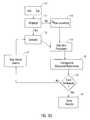
- FIG. 32is a representation of a single zone multiphase flow system in accordance with the present invention.
- FIG. 33is a block diagram of a multiphase flow model in accordance with the present invention.
- FIG. 34is a graph representing a numerical test of a multiphase flow model incorporating pressure and temperature measurements to determine Oil Rate
- FIG. 35is a graph representing a numerical test of a multiphase flow model incorporating pressure and temperature measurements to determine Water Rate
- FIG. 36is a graph of the error function created for a multiphase flow model incorporating pressure and temperature measurements to determine phase flow rates
- FIG. 37is a graph representing a numerical test of a multiphase flow model incorporating sound speed, velocity and pressure measurements to determine Gas Rate;
- FIG. 38is a graph representing a numerical test of a multiphase flow model incorporating sound speed, velocity and pressure measurements to determine Oil Rate;
- FIG. 39is a graph representing a numerical test of a multiphase flow model incorporating sound speed, velocity and pressure measurements to determine Water Rate;
- FIG. 40is a graph of the error function created for a multiphase flow model incorporating sound speed, velocity and pressure measurements to determine phase flow rates.
- FIG. 41is a graphical representation of a multizone multiphase flow system in accordance with the present invention.
- FIG. 1there is shown a prior art MPFM 10 for monitoring flow rates of a multi-phase fluid represented by arrow 12 flowing within a pipe 14 .
- Math model 16 of MPFM 10utilizes output from sensor 18 and at least sensor 20 to predict the phase fraction flow rate of fluid 12 .
- Sensors 18 , 20are typical prior art sensors described above that provide parameters to the model 16 such as temperature, pressure, and phase fraction.
- Model 16utilizes the output of sensors 18 , 20 to determine, among other things, axial momentum and radial heat transfer of the fluid 12 . The axial momentum and radial heat transfer are calibrated to phase fraction volumetric flow rates at known conditions to provide an estimate of the global multi-phase flow rate Qw.
- a MPFM 30 of the present inventionwhich utilizes sensor 32 and sensor 34 .
- Sensor 32 and sensor 34may comprise a single sensor or a sensor system comprising multiple sensors or sensor arrays.
- Sensors 32 and 34which include fiber optic or electronically passive sensors, provide temperature, pressure, sound speed measurements and/or bulk velocity measurements of a multi-phase fluid 12 to system model 16 .
- One sensor systemreferred to as a “flow meter,” that can be used to measure these parameters is disclosed in U.S. application Ser. No. 09/740,760, entitled “Apparatus for Sensing Fluid in a Pipe,” filed Nov. 29, 2000, which is incorporated herein by reference in its entirety. This particular flow meter combines a fluid sound speed sensor with a velocity sensor.
- Model 16utilizes the speed of sound and/or bulk velocity information to provide a robust and accurate multi-phase flow rate Qw to monitor multiphase flow production. Because the present invention preferably employs a fluid sound speed and fluid velocity, the methods for determining these parameters are disclosed in detail in the following sections.
- the present inventionutilizes acoustic sensors 32 , 34 and methods such as that described in U.S. Pat. No. 6,354,147, entitled “Fluid Parameter Measurement in Pipes Using Acoustic Pressure,” which is incorporated herein by reference in its entirety, and discussed in further detail below.
- the sensorsprovide sound speed measurements to model 16 by measuring acoustic pressure waves in the fluid 12 .
- the inventionpreferably uses acoustic signals having lower frequencies (and thus longer wavelengths) than those used for ultrasonic meters, such as below about 20 kHz (depending on pipe diameter). Typically, for 3-7 inch production tubing, the desired frequency range is between 100-2000 hz.
- the inventionis more tolerant to the introduction of gas, sand, slugs, or other inhomogeneities in the fluid.
- the embodiment described belowmay also be referred to as a phase fraction meter or sound speed meter.
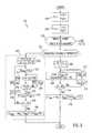
- FIG. 3discloses a speed of sound meter that could be used for either of the sensors 32 or 34 in FIG. 2 .
- the pipe, or conduit, 14has three unsteady pressure sensors 114 , 116 , 118 , located at three locations x 1 , x 2 , x 3 along the pipe 14 .
- the sensors 114 , 116 , 118provide pressure time-varying signals P 1 (t), P 2 (t), P 3 (t) on lines 120 , 122 , 124 , to known Fast Fourier Transform (FFT) logics 126 , 128 , 130 , respectively.
- FFTFast Fourier Transform
- the FFT logics 126 , 128 , 130calculate the Fourier transform of the time-based input signals P 1 (t), P 2 (t), P 3 (t) and provide complex frequency domain (or frequency based) signals P 1 ( ⁇ ), P 2 ( ⁇ ), P 3 ( ⁇ ) on lines 132 , 134 , 136 indicative of the frequency content of the input signals.
- any other technique for obtaining the frequency domain characteristics of the signals P 1 (t), P 2 (t), P 3 (t)may be used.
- the cross-spectral density and the power spectral densitymay be used to form frequency domain transfer functions (or frequency responses or ratios) discussed below.
- the frequency signals P 1 ( ⁇ ), P 2 ( ⁇ ), P 3 ( ⁇ )are fed to an ⁇ mix -Mx Calculation Logic 140 which provides a signal on a line 146 indicative of the speed of sound of the mixture ⁇ mix .
- the ⁇ mix signalis provided to map (or equation) logic 148 , which converts ⁇ mix to a percent composition of the fluid and provides a “% Comp” signal on line 150 .
- map (or equation) logic 148which converts ⁇ mix to a percent composition of the fluid and provides a “% Comp” signal on line 150 .
- the calculation logic 140may also provide a signal Mx on a line 159 indicative of the Mach number (as discussed below).
- the acoustic pressure field P(x,t) at a location x along a pipewhere the wavelength ⁇ of the acoustic waves to be measured is long compared to the diameter d of the pipe 14 (i.e., ⁇ /d>>1), may be expressed as a superposition of a right traveling wave and a left traveling wave, as follows:
- ⁇ mixis the speed of sound in the mixture in the pipe
- ⁇is frequency (in rad/sec)
- M xis the axial Mach number of the flow of the mixture within the pipe, where: M x ⁇ V m ⁇ ⁇ i ⁇ ⁇ x a m ⁇ ⁇ i ⁇ ⁇ x Eq . ⁇ 3
- V mixis the axial velocity of the mixture.
- the axial Mach numberrepresents the average velocity of the mixture and the low frequency acoustic field description remains substantially unaltered.
- the frequency domain representation P(x, ⁇ ) of the time-based acoustic pressure field P(x,t) within a pipeis the coefficient of the e i ⁇ t term of Eq. 1:
- Ris defined as the reflection coefficient
- Eq. 9may be solved numerically, for example, by defining an “error” or residual term as the magnitude of the left side of Eq. 9, and iterating to minimize the error term.
- the speed of sound in the fluidmay be computed by either: (1) varying ⁇ mix while minimizing an error term, (2) calculating a logarithmic relationship between the acoustic pressure variation signals, or (3) calculating a trigonometric relationship between the acoustic pressure variation signals.
- the axial velocity of the flow in the pipeis small compared to the speed of sound in the mixture (i.e., the axial Mach number M x is small compared to one).
- the axial velocity of the oil V oil in a typical oil wellis about 10 ft/sec and the speed of sound in oil ⁇ oil is about 4,000 ft/sec.
- the value for ⁇ mixcan be iteratively determined by evaluating the error term at a given frequency ⁇ and varying ⁇ mix until the error term goes to zero.
- the value of ⁇ mix at which the magnitude of the error term equals zero (or is a minimum)corresponds to the correct value of the speed of sound in the mixture ⁇ mix .
- Eq. 10is a function of frequency ⁇ , the speed of sound ⁇ mix at which the error goes to zero is the same for each frequency ⁇ evaluated.
- the multiple measurementsmay be weighted, averaged or filtered to provide a single more robust measurement of the speed of sound in the fluid.
- the error term of Eq. 10constitutes a family of curves, one curve for each frequency ⁇ , where the value of the error is evaluated for values of ⁇ mix varied from ⁇ water (5,000 ft/sec) to ⁇ oil (4,000 ft/sec) at each frequency varied from 5 to 200 Hz in 5 Hz increments. Other frequencies may be used if desired.
- the speed of sound ⁇ mix where the error goes to zero (or is minimized)is the same for each frequency ⁇ evaluated. In this case, the error is minimized at a point 170 when ⁇ mix is 4335 ft/sec.
- the analytical solution to Eq. 10 as reflected in Eqs. 12 and 13is valid primarily for the frequencies for which the length of the test section 151 along the pipe 14 (i.e., x 3 ⁇ x 1 or 2 ⁇ x for equally spaced sensors) is shorter than the wavelength ⁇ of the acoustic waves to be measured. This restriction results because of the multiple possible solutions for Eq. 10.
- Alternative solutions to Eq. 10 for other frequency rangesmay be derived using a variety of known techniques.
- Eq. 14is particularly useful due to its simple geometric form, from which ⁇ mix can be easily interpreted.
- ⁇ mixcan be determined directly by inspection from a digital signal analyzer (or other similar instrument) set up to provide a display indicative of the left side of Eq. 14, which will be a cosine curve from which ⁇ mix may be readily obtained. For example, at the zero crossing of the cosine wave, ⁇ mix will be equal to 2 ⁇ X/ ⁇ .
- Eq. 14may be used to determine ⁇ mix using an iterative approach where a measured function is calculated from the left side of Eq. 14 (using the measured pressures), which is compared to a cosine curve of the right side of Eq. 14, where ⁇ mix is varied until it substantially matches the measured function.
- Various other curve fitting, parameter identification, and/or minimum error or solution techniquesmay be used to determine the value of ⁇ mix that provides the best fit to satisfy Eq. 14.
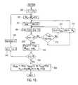
- the calculation logic 140begins at step 200 where P 12 is calculated as the ratio of P 1 ( ⁇ )/P 2 ( ⁇ ), and at step 202 where P 13 is calculated as the ratio of P 1 ( ⁇ )/P 3 ( ⁇ ).
- step 208calculates ⁇ mix (n) from the closed form solution of Eq. 13.
- step 210checks whether the logic 140 has calculated ⁇ mix at a predetermined number of frequencies, e.g., 10. If n is not greater than 10, steps 212 and 214 increment the counter n by one and increases the frequency ⁇ by a predetermined amount (e.g., 10 Hz) and step 208 is repeated. If the logic 140 has calculated ⁇ mix at 10 frequencies, logic 140 goes to step 216 , which determines an average value for ⁇ mix using the values of ⁇ mix (n) over the 10 frequencies, and the logic 140 then exits.
- a predetermined number of frequenciese.g. 10 Hz
- step 232checks whether n is greater than or equal to 10. If not, step 234 increments n by one and step 236 increases the frequency ⁇ by a predetermined amount (e.g., 10 Hz) and continues at step 222 as shown in FIG. 15 . If n is greater than or equal to 10, step 238 calculates an average value for ⁇ mix over the 10 frequencies, and the logic 140 ends.
- a predetermined amounte.g. 10 Hz
- step 306calculates the error term of Eq. 10.
- step 312increases ⁇ mix by a predetermined amount (e.g., 1 ft/sec) and the logic goes back to step 306 . If the result of step 310 is yes, step 314 increases Mx by a predetermined amount (e.g., 1) and the logic goes back to step 304 .
- a predetermined amounte.g. 1 ft/sec
- a predetermined amounte.g. 10 Hz
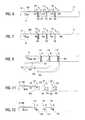
- pairs of Bragg gratings( 410 , 412 ), ( 414 , 416 ), ( 418 , 420 ) may be located along the fiber 400 at opposite ends of each of the wraps 402 , 404 , 406 , respectively.
- the grating pairsare used to multiplex the pressure signals P 1 , P 2 , P 3 to identify the individual wraps from optical return signals.
- the first pair of gratings 410 , 412 around the wrap 402may have a common reflection wavelength ⁇ 1
- the second pair of gratings 414 , 416 around the wrap 404may have a common reflection wavelength ⁇ 2 , but different from that of the first pair of gratings 410 , 412
- the third pair of gratings 418 , 420 around the wrap 406have a common reflection wavelength ⁇ 3 , which is different from ⁇ 1 and ⁇ 2 .
- the fiber 400may continue to other sensors as shown by reference numeral 17 or return the optical signals to the instrument as shown by reference numeral 15 .
- a series of Bragg gratings 460 , 462 , 464 , 466 with only one grating between each of the wraps 402 , 404 , 406may be used, each having a common reflection wavelength ⁇ 1 .
- the wraps 402 , 404 , 406 with the gratings 410 , 412 , 414 , 416 , 418 , 420 (FIG. 22) or with the gratings 460 , 462 , 464 , 466 (FIG. 7)may be configured in numerous known ways to precisely measure the fiber length or change in fiber length, such as by interferometric, Fabry Perot, time-of-flight, or other known arrangements.
- time-of-flightor Time-Division-Multiplexing; TDM
- TDMTime-Division-Multiplexing
- the gratingsare shown oriented axially with respect to pipe 14 in FIGS. 6 and 7, the gratings may be oriented along the pipe 14 axially, circumferentially, or in any other orientations. Depending on the orientation, the grating may measure deformations in the pipe wall with varying levels of sensitivity. If the grating reflection wavelength varies with internal pressure changes, such variation may be desired for certain configurations (e.g., fiber lasers) or may be compensated for in the optical instrumentation for other configurations, e.g., by allowing for a predetermined range in reflection wavelength shift for each pair of gratings. Alternatively, instead of each of the wraps being connected in series, they may be connected in parallel, e.g., by using optical couplers (not shown) prior to each of the wraps, each coupled to the common fiber 400 .
- optical couplersnot shown
- the sensors 114 , 116 , 118may also be formed as a purely interferometric sensor by wrapping the pipe 14 with the wraps 402 , 404 , 406 without using Bragg gratings, in which case separate fibers 430 , 432 , 434 may be fed to the separate, corresponding wraps 402 , 404 , 406 .
- known interferometric techniquesmay be used to determine the length or change in length of the fiber wraps 402 , 404 , 406 around the pipe 14 due to pressure changes within the pipe. These known interferometric techniques include the Mach Zehnder or Michaelson Interferometric techniques that are described in U.S. Pat. No.
- the wraps 402 , 404 , 406may have alternative geometries, such as a “radiator coil” geometry, as shown in FIG. 9, or a “race-track” geometry, as shown in FIG. 10 . Both of these alternative geometries are shown in a side view as if the pipe 14 is cut axially and laid flat.
- the wraps 402 , 404 , 406are not necessarily wrapped 360 degrees around the pipe, but may be disposed over a predetermined portion of the circumference of the pipe 14 with a length long enough to optically detect the changes to the pipe circumference.
- wrapsmay be used if desired. Also, for any geometry of the wraps described, more than one layer of fiber may be used depending on the overall fiber length desired.
- the desired axial length of any particular wrapis set depending on the characteristics of the ac pressure desired to be measured, for example the axial length of the pressure disturbance caused by a vortex to be measured.
- embodiments of the present inventioninclude configurations wherein instead of using the wraps 402 , 404 , 406 , the fiber 400 may have shorter sections that are disposed around at least a portion of the circumference of the pipe 14 that can optically detect changes to the pipe circumference. It is further within the scope of the present invention that sensors may comprise an optical fiber 400 disposed in a helical pattern (not shown) about pipe 14 . As discussed above, the orientation of the strain sensing element will vary the sensitivity to deflections in pipe wall deformations caused by unsteady pressure signals in the pipe 14 .
- FIG. 13illustrates an embodiment of a sound speed measurement system in an oil or gas well application.
- the sensing section 151may be connected to or part of the production tubing 602 (analogous to the pipe 14 in the test section 151 ) within a well 600 .
- An isolation sleeve 510may be located over the sensors 114 , 116 , 118 and attached to the pipe 602 at its axial ends to protect the sensors 114 , 116 , 118 (or fibers) from damage during deployment, use, or retrieval.
- the isolation sleevemay also help isolate the sensors 114 , 116 , 118 from acoustic external pressure effects that may exist outside the pipe 602 , and/or to help isolate ac pressures in the pipe 602 from ac pressures outside the pipe 602 .
- the sensors 114 , 116 , 118are connected to a cable 606 which may comprise an optical fiber 400 and is connected to a transceiver/converter 610 located outside the well 600 .
- the transceiver/converter 610may be used to receive and transmit optical signals 604 to the sensors 114 , 116 , 118 and provides output signals indicative of the pressure P 1 , P 2 , P 3 at the sensors 114 , 116 , 118 on the lines 120 , 122 , 124 , respectively. Also, the transceiver/converter 610 may be part of the Fluid Parameter Logic 160 . The transceiver/converter 610 may be any device that performs the corresponding functions described.
- the transceiver/converter 610 together with the optical sensors described abovemay use any type of optical grating-based measurement technique, e.g., scanning interferometric, scanning Fabry Perot, acousto-optic-tuned filter (AOTF), optical filter, time-of-flight, and may use WDM and/or TDM, etc., having sufficient sensitivity to measure the ac pressures within the pipe, such as that described in one or more of the following references: A. Kersey et al., “Multiplexed fiber Bragg grating strain-sensor system with a Fabry-Perot wavelength filter,” Opt. Letters, Vol. 18, No. 16, August 1993; U.S. Pat. No.
- sensors 32 , 34provide sound speed measurements, by the method described above, which significantly enhance phase fraction determination over that of the prior art.
- Prior art phase fraction metersmicrowave, dual beam densitometer, etc.
- An advantage of the present inventionis that a sound speed measurement does not uniquely determine the phase fractions, but rather provides a constraint on a combination of the phase fractions.
- sound speed measurementsare analogous to density measurements.
- the density of a well-mixed mixture of oil, water, and gas (immiscible mixture)is related to the phase fraction and the density of the individual components via the following relation:
- ⁇is the density of the mix or constituent of the multi-component mixture
- ⁇is the sound speed of the mix or constituent of the mixture
- ⁇is the volumetric phase fraction of the mix or constituent of the mixture.
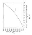
- a curve 110shows the speed of sound in the mixture ⁇ mix plotted as a function of water volume fraction.
- the values used for density ( ⁇ ) and speed of sound ( ⁇ ) in oil and waterare as follows:
- the present inventioncan be used to measure fluid volume fractions of a mixture of any number of fluids in which the speed of sound of the mixture ⁇ mix is related to (or is substantially determined by) the volume fractions of two constituents of the mixture, e.g., oil/water, oil/gas, water/gas.
- the present inventioncan be used to measure the speed of sound of any mixture and can then be used in combination with other known quantities to derive phase content of mixtures with multiple (more than two) constituents.
- the present inventionfurther includes velocity sensors 32 , 34 and methods for determining bulk velocity or volumetric flow rates such as that described in U.S. patent application Ser. No. 09/346,607, entitled, “Flow Rate Measurement Using Unsteady Pressures,” filed Jul. 2, 1999, which is incorporated herein by reference in its entirety, and discussed in further detail below. Similar to that described previously with regard to sound speed measurements, the volumetric flow rate based on a cross correlation based flow rate measurement significantly improves distributed measurement flow rate determination utilizing model 16 . For well-mixed flows of fluid 12 within a pipe 14 , a homogeneous model 16 which assumes that all the phases are flowing at the same velocity may be sufficient.
- slip modelsmay be required to translate flow velocities provided from cross correlation measurements into individual component flow rates.
- the present inventionincorporates cross correlation measurements that improve the predictive performance of the model 16 for multi-phase flow Qw information.
- the sensorsprovide bulk velocity measurement to model 16 (FIG. 2) by measuring vortical pressures in the fluid.
- FIG. 2the embodiment described below may be referred to as a flow meter.
- a velocity and flow measurement systemincludes a sensing section 710 along a pipe, or conduit, 14 and a velocity logic section 740 .
- the pipe 14has two measurement regions 714 , 716 located a distance ⁇ X apart along the pipe 14 .
- At the first measurement region 714are two unsteady (or dynamic or ac) pressure sensors 718 , 720 , located a distance X 1 apart, capable of measuring unsteady vortical pressures in the pipe 14
- the second measurement region 716are two other unsteady pressure sensors 722 , 724 , located a distance X 2 apart, also capable of measuring unsteady vortical pressures in the pipe 14 .
- Each pair of pressure sensors 718 , 720 and 722 , 724act as spatial filters to remove certain acoustic signals from the unsteady pressure signals, and the distances X 1 , X 2 are determined by the desired filtering characteristic for each spatial filter, as discussed hereinafter.
- the flow measurement system 710 of the present inventionmeasures velocities associated with unsteady flow fields and/or pressure disturbances represented by 715 such as turbulent eddies (or vortical flow fields), inhomogeneities in the flow (such as bubbles, slugs, and the like), or any other properties of the flow, fluid, or pressure, having time varying or stochastic properties in the form of unsteady pressures.
- the vortical flow fields 715are, in general, comprised of pressure disturbances having a wide variation in length scales and which have a variety of coherence length scales such as that described in the reference “Sound and Sources of Sound,” A. P. Dowling et al, Halsted Press, 1983.
- Vortical flow fieldsoften convect at or near the mean velocity of at least one of the fluids within a mixture flowing in a pipe. More specifically, the vortices convect in a predictable manner with reference to the fluids.
- the vortical pressure disturbances 715 that contain information regarding convection velocityhave temporal and spatial length scales as well as coherence length scales that differ from other disturbances in the flow.
- the present inventionutilizes these properties to preferentially select disturbances of a desired axial length scale and coherence length scale as will be more fully described hereinafter.
- the terms vortical flow field and vortical pressure fieldwill be used to describe the above-described group of unsteady pressure fields having temporal and spatial length and coherence scales described.
- the pressures P 1 , P 2 , P 3 , P 4may be measured through holes in the pipe 14 ported to external pressure sensors or by other techniques discussed hereinafter.
- the pressure sensors 718 , 720 , 722 , 724provide time-based pressure signals P 1 (t), P 2 (t), P 3 (t), P 4 (t) on lines 730 , 732 , 734 , 736 , respectively, to Velocity Logic 740 which provides a convection velocity signal U c (t) on a line 742 which is related to an average flow rate U f (t) of the fluid flowing in the pipe 14 (where fluid may comprise one or more liquids and/or gases; where the gas(es) may be dissolved in the liquid or in free gas form, and wherein the fluid may include non-liquid elements).
- the pressure signal P 1 (t) on the line 730is provided to a positive input of a summer 744 and the pressure signal P 2 (t) on the line 732 is provided to a negative input of the summer 744 .
- the line 745is fed to bandpass filter 746 , which passes a predetermined passband of frequencies and attenuates frequencies outside the passband.
- the passband of the filter 746is set to filter out (or attenuate) the dc portion and the high frequency portion of the input signals and to pass the frequencies therebetween.
- bandpass filter 746is set to pass frequencies from about 1 Hz to about 100 Hz, for a 3 inch ID pipe flowing water at 10 ft/sec. Other passbands may be used in other embodiments, if desired.
- Bandpass filter 746provides a filtered signal P asf1 on a line 748 to Cross-Correlation Logic 750 , described below.
- the pressure signal P 3 (t) on the line 734is provided to a positive input of a summer 754 and the pressure signal P 4 (t) on the line 736 is provided to a negative input of the summer 754 .
- the pressure sensors 722 , 724 together with the summer 754create a spatial filter 735 .
- the line 755is fed to a bandpass filter 756 , similar to the bandpass filter 746 discussed hereinbefore, which passes frequencies within the passband and attenuates frequencies outside the passband.
- the filter 756provides a filtered signal P asf2 on a line 758 to the Cross-Correlation Logic 750 .
- the signs on the summers 744 , 754may be swapped if desired, provided the signs of both summers 744 , 754 are swapped together.
- the pressure signals P 1 , P 2 , P 3 , P 4may be scaled prior to presentation to the summers 744 , 754 .
- the Cross-Correlation Logic 750calculates a known time domain cross-correlation between the signals P asf1 and P asf2 on the lines 748 , 758 , respectively, and provides an output signal on a line 760 indicative of the time delay ⁇ it takes for an vortical flow field 715 (or vortex, stochastic, or vortical structure, field, disturbance or perturbation within the flow) to propagate from one sensing region 714 to the other sensing region 716 .
- vortical flow disturbancesare coherent dynamic conditions that can occur in the flow which substantially decay (by a predetermined amount) over a predetermined distance (or coherence length) and convect (or flow) at or near the average velocity of the fluid flow.
- the vortical flow field 715also has a stochastic or vortical pressure disturbance associated with it.
- the vortical flow disturbances 715are distributed throughout the flow, particularly in high shear regions, such as boundary layers (e.g., along the inner wall of the pipe 14 ) and are shown as discrete vortical flow fields 715 .
- the propagation time delay ⁇is related to the velocity of the flow by the distance ⁇ X between the measurement regions 714 , 716 , as discussed below.
- a spacing signal ⁇ X on a line 762 indicative of the distance ⁇ X between the sensing regions 714 , 716is divided by the time delay signal ⁇ on the line 760 by a divider 764 which provides an output signal on the line 742 indicative of the convection velocity U c (t) of the fluid flowing in the pipe 14 , which is related to (or proportional to or approximately equal to) the average (or mean) flow velocity U f (t) of the fluid, as defined below:
- the convection velocity U c (t)may then be calibrated to more precisely determine the mean velocity U f (t) if desired.
- the result of such calibrationmay require multiplying the value of the convection velocity U c (t) by a calibration constant (gain) and/or adding a calibration offset to obtain the mean flow velocity U f (t) with the desired accuracy. For some applications, such calibration may not be required to meet the desired accuracy.
- the velocities U f (t), U c (t)may be converted to volumetric flow rate by multiplying the velocity by the cross-sectional area of the pipe.
- cross-correlationmay be used to determine the time delay ⁇ between two signals y 1 (t), y 2 (t) separated by a known distance ⁇ X, that are indicative of quantities 780 that convect with the flow (e.g., density perturbations, concentration perturbations, temperature perturbations, vortical pressure disturbances, and other quantities).
- quantities 780that convect with the flow
- the signal y 2 (t)lags behind the signal y 1 (t) by 0.15 seconds.
- a time domain cross-correlationis taken between the two signals y 1 (t), y 2 (t)
- the resultis shown in FIG. 19 as a curve 784 .
- the highest peak 786 of the curve 784shows the best fit for the time lag ⁇ between the two signals y 1 (t), y 2 (t) is at 0.15 seconds which matches the reference time delay shown in FIG. 18 .
- the vortical pressure disturbances observed at the downstream location 716are substantially a time lagged version of the vortical pressure disturbances observed at the upstream location 714 .
- the total vortical pressure perturbations or disturbances in a pipemay be expressed as being comprised of vortical pressure disturbances (P vortical ), acoustic pressure disturbances (P acoustic ) and other types of pressure disturbances (P other ) as shown below expressed in terms of axial position along the pipe at any point in time:
- the unsteady pressure disturbances P vorticalcan be masked by the acoustic pressure disturbances P acoustic and the other types of pressure disturbances P other .
- the presence of the acoustic pressure disturbances that propagate both upstream and downstream at the speed of sound in the fluid (sonic velocity)can prohibit the direct measurement of velocity from cross-correlation of direct vortical pressure measurements.
- the present inventionuses temporal and spatial filtering to precondition the pressure signals to effectively filter out the acoustic pressure disturbances P acoustic and other long wavelength (compared to the sensor spacing) pressure disturbances in the pipe 14 at the two sensing regions 714 , 716 and retain a substantial portion of the vortical pressure disturbances P vortical associated with the vortical flow field 715 and any other short wavelength (compared to the sensor spacing) low frequency pressure disturbances P other .
- the low frequency pressure disturbances P otherare small, they will not substantially impair the measurement accuracy of P vortical .
- the P vortical dominated signals from the two regions 714 , 716are then cross-correlated to determine the time delay ⁇ between the two sensing locations 714 , 716 . More specifically, at the sensing region 714 , the difference between the two pressure sensors 718 , 720 creates a spatial filter 733 that effectively filters out (or attenuates) acoustic disturbances for which the wavelength ⁇ of the acoustic waves propagating along the fluid is long (e.g., ten-to-one) compared to the spacing X 1 between the sensors. Likewise the same is true for spatial filter 735 . Other wavelength to sensor spacing ratios may be used to characterize the filtering, provided the wavelength to sensor spacing ratio is sufficient to satisfy the two-to-one spatial aliasing Nyquist criteria.
- PSDpower spectral density
- a curve 790that has a flat region (or bandwidth) up to a frequency F v and then decreases with increasing frequency f.
- the value of F vis approximately equal to U/r, where U is the flow rate and r is the radius of the pipe.
- Uis the flow rate
- ris the radius of the pipe.
- the bandwidth F v of the vortical pressure disturbances P vorticalwould be about 80 Hz (10/0.125).
- the PSD of the acoustic pressure disturbances P acoustichas a profile that is determined by the environment and other factors and is indicated in the figure by an arbitrary curve 791 , and typically has both low and high frequency components.
- the acoustic spatial filters 733 , 735 (FIG. 16) discussed hereinbeforeblock or attenuate wavelengths longer than ⁇ as and frequencies below ⁇ as , as indicated by the region 796 .
- the bandpass filters (BPF) 746 , 756(FIG. 16) block or attenuate high frequencies above ⁇ pb having short and long wavelengths and pass frequencies below ⁇ as where the P vortical signals exist.
- the resultant filtered signals P asf1 , P asf2 on the lines 748 , 758 (FIG. 16)will be dominated by the short wavelength unsteady pressure disturbances P Vortical at frequencies below ⁇ pb and as indicated by a portion 794 of the curve 790 in the BPF passband 795 (FIG. 20 ).
- the spatial filters 733 , 735(FIG. 16) block the long wavelengths, which, for the acoustic pressure disturbances P acoustic , occur at low frequencies as indicated to the left of a dashed line 792 at frequencies below the frequency ⁇ as .
- a dashed line 793indicates the attenuation of the acoustic pressure P acoustic signal 791 below the frequency ⁇ as at the output of the spatial filters.
- the vortical pressure disturbances P vorticalare substantially not attenuated (or only slightly attenuated) because P vortical has short wavelengths at low frequencies that are substantially passed by the spatial filter.
- the BPF's 746 , 756(FIG. 16) block or attenuate frequencies outside the passband indicated by a range of frequencies 795 , and passes the unsteady pressure disturbances associated with stochastic flow fields 715 (FIG. 16) within the passband 795 .
- the filters 746 , 756may comprise low pass filters, having a bandwidth similar to the upper band of the high pass filters discussed hereinbefore. If a low pass filter is used as the filters 746 , 756 , the passband is shown as a range of frequencies 789 . It should be understood that the filters 746 , 756 are not required for the present invention if the PSD of the acoustic pressure disturbances P acoustic has substantially no or low PSD energy content in frequencies above the stopband of the spatial filter that does not adversely affect the measurement accuracy.
- the frequency power spectrum for P 1 and P 2are shown by curves 800 , 802 , respectively, for water flowing in an horizontal flow loop at a velocity of 11.2 ft/sec in a 2 inch diameter schedule 780 pipe using conventional piezoelectric ac pressure transducers.
- the power spectra of the curves 800 , 802are nearly identical.
- the power spectrum of the difference P as1 , between the two signals P 1 , P 2 , shown by a curve 804is reduced in certain frequency bands (e.g., 100-150 Hz) and increased in other frequency bands (e.g., 200-250 Hz) as compared to the individual signals 800 , 802 .
- the cross correlation between the signals P as1 (or P 1 ⁇ P 2 ) and P as2 (P 3 ⁇ P 4 )is shown as a curve 810 .
- the highest peak 812indicates the best fit for the time lag between the two signals P as1 , P as2 as 0.015 seconds. Because the four sensors P 1 to P 4 were evenly axially spaced 1 inch apart, the effective distance ⁇ X between the sensor pairs is 2 inches. Thus, the velocity measured from Eq. 18 is 11.1 ft/sec (2/12/0.015) using the present invention and the actual velocity was 11.2 ft/sec.
- a solid line 820shows the reference velocity
- the triangles 822are the measured data
- a line 824is a curve fit of the data 822 . This illustrates that the present invention predicts the flow velocity within a pipe (or conduit).
- the ac pressure sensors 718 - 724may be configured using an optical fiber 900 that is coiled or wrapped around and attached to the pipe 14 at each of the pressure sensor locations as indicated by the coils or wraps 902 , 904 , 906 , 908 for the pressures P 1 , P 2 , P 3 , P 4 , respectively.
- the fiber wraps 902 - 908are wrapped around the pipe 14 such that the length of each of the fiber wraps 902 - 908 changes with changes in the pipe loop strain in response to unsteady pressure variations within the pipe 14 and thus internal pipe pressure is measured at the respective axial location.
- Such fiber length changesare measured using known optical measurement techniques as discussed hereinafter.
- Each of the wrapsmeasures substantially the circumferentially averaged pressure within the pipe 14 at a corresponding axial location on the pipe 14 . Also, the wraps provide axially averaged pressure over the axial length of a given wrap. While the structure of the pipe 14 provides some spatial filtering of short wavelength disturbances, we have found that the basic principle of operation of the invention remains substantially the same as that for the point sensors described previously.
- pairs of Bragg gratings( 910 , 912 ), ( 914 , 916 ), ( 918 , 920 ), ( 922 , 924 ) may be located along the fiber 900 at opposite ends of each of the wraps 902 , 904 , 906 , 908 , respectively.
- the grating pairsare used to multiplex the pressure signals P 1 , P 2 , P 3 , P 4 to identify the individual wraps from optical return signals.
- the first pair of gratings 910 , 912 around the wrap 902may have a common reflection wavelength ⁇ 1
- the second pair of gratings 914 , 916 around the wrap 904may have a common reflection wavelength ⁇ 2 , but different from that of the first pair of gratings 910 , 912
- the third pair of gratings 918 , 920 around the wrap 906have a common reflection wavelength ⁇ 3 , which is different from ⁇ 1 , ⁇ 2
- the fourth pair of gratings 922 , 924 around the wrap 908have a common reflection wavelength ⁇ 4 , which is different from ⁇ 1 , ⁇ 2 , ⁇ 3
- the fiber 400may continue to other sensors as shown by reference numeral 17 or return the optical signals to the instrument as shown by reference numeral 15 .
- a series of Bragg gratings 960 - 968 with only one grating between each of the wraps 902 - 908may be used each having a common reflection wavelength ⁇ 1 .
- the wraps 902 - 908 with the gratings 910 - 924 (FIG. 24) or with the gratings 960 - 968 (FIG. 25)may be configured in numerous known ways to precisely measure the fiber length or change in fiber length, such as an interferometric, Fabry Perot, time-of-flight, or other known arrangements.
- An example of a Fabry Perot techniqueis described in U.S. Pat. No. 4,950,883, entitled “Fiber Optic Sensor Arrangement Having Reflective Gratings Responsive to Particular Wavelengths,” to Glenn.
- time-of-flightor Time-Division-Multiplexing; TDM
- TDMTime-Division-Multiplexing
- the gratings 910 - 924are shown oriented axially with respect to the pipe 14 , in FIGS. 24 and 25, they may be oriented along the pipe 14 axially, circumferentially, or in any other orientations. Depending on the orientation, the grating may measure deformations in the pipe wall 952 with varying levels of sensitivity. If the grating reflection wavelength varies with internal pressure changes, such variation may be desired for certain configurations (e.g., fiber lasers) or may be compensated for in the optical instrumentation for other configurations, e.g., by allowing for a predetermined range in reflection wavelength shift for each pair of gratings. Alternatively, instead of each of the wraps being connected in series, they may be connected in parallel, e.g., by using optical couplers (not shown) prior to each of the wraps, each coupled to the common fiber 900 .
- optical couplersnot shown
- the sensors 718 - 724may also be formed as individual non-multiplexed interferometric sensor by wrapping the pipe 14 with the wraps 902 - 908 without using Bragg gratings where separate fibers 930 , 932 , 934 , 936 may be fed to the separate wraps 902 , 904 , 906 , 908 , respectively.
- known interferometric techniquesmay be used to determine the length or change in length of the fiber 710 around the pipe 14 due to pressure changes, such as Mach Zehnder or Michaelson Interferometric techniques, such as that described in U.S. Pat. No. 5,218,197, entitled “Method And Apparatus For The Non-Invasive Measurement Of Pressure Inside Pipes Using A Fiber Optic Interferometer Sensor,” to Carroll.
- the interferometric wrapsmay be multiplexed such as is described in Dandridge, et al, “Fiber Optic Sensors for Navy Applications,” IEEE, February 1991, or Dandridge, et al, “Multiplexed Interferometric Fiber Sensor Arrays,” SPIE, Vol. 1586, 1991, pp. 176-183. Other techniques to determine the change in fiber length may be used. Also, reference optical coils (not shown) may be used for certain interferometric approaches and may also be located on or around the pipe 14 but may be designed to be insensitive to pressure variations.
- the wraps 902 - 908may have alternative geometries, such as a “radiator coil” geometry (FIG. 27) or a “race-track” geometry (FIG. 28 ), which are shown in a side view as if the pipe 14 is cut axially and laid flat.
- the wraps 902 - 908are not necessarily wrapped 360 degrees around the pipe, but may be disposed over a predetermined portion of the circumference of the pipe 14 , and have a length long enough to optically detect the changes to the pipe circumference. Other geometries for the wraps may be used if desired.
- more than one layer of fibermay be used depending on the overall fiber length desired.
- the desired axial length of any particular wrapis set depending on the characteristics of the ac pressure desired to be measured, for example the axial length of the pressure disturbance caused by a vortex to be measured.
- embodiments of the present inventioninclude configurations wherein instead of using the wraps 902 - 908 , the fiber 900 may have shorter sections that are disposed around at least a portion of the circumference of the pipe 14 that can optically detect changes to the pipe circumference. It is further within the scope of the present invention that sensors may comprise an optical fiber 900 disposed in a helical pattern (not shown) about pipe 14 . As discussed above, the orientation of the strain sensing element will vary the sensitivity to deflections in pipe wall 952 caused by unsteady pressure transients in the pipe 14 .
- the pairs of Bragg gratings( 910 , 912 ), ( 914 , 916 ), ( 918 , 920 ), ( 922 , 924 ) are located along the fiber 900 with sections 980 - 986 of the fiber 900 between each of the grating pairs, respectively.
- known Fabry Perot, interferometric, time-of-flight or fiber laser sensing techniquesmay be used to measure the strain in the pipe, in a manner similar to that described in the aforementioned references.
- individual gratings 970 - 976may be disposed on the pipe and used to sense the unsteady variations in strain in the pipe 14 (and thus the unsteady pressure within the pipe) at the sensing locations.
- the grating reflection wavelength shiftwill be indicative of changes in pipe diameter and thus pressure.
- optical strain gageAny other technique or configuration for an optical strain gage may be used.
- the type of optical strain gage technique and optical signal analysis approachis not critical to the present invention, and the scope of the invention is not intended to be limited to any particular technique or approach.
- the present inventionwill also work over a wide range of oil/water/gas mixtures. Also, the invention will work for very low flow velocities, e.g., at or below 1 ft/sec (or about 20.03 gal/min, in a 3 inch diameter ID pipe) and has no maximum flow rate limit. Further, the invention will work with the pipe 14 being oriented vertical, horizontal, or any other orientation. Also the invention will work equally well independent of the direction of the flow along the pipe 14 .
- the thickness and rigidity of the outer wall of the pipe 14is related to the acceptable spacing X 1 (FIG. 1) between the sensors 718 , 720 of the spatial filter 733 . More specifically, the thinner or less rigid the pipe 14 wall, the closer the sensors 718 , 720 can be to each other.
- the distance X 1 between the two sensors 718 , 720should be larger than the spatial length of the vortical pressure field 715 such that each of the sensors 718 , 720 can independently measure the propagating vortical pressure field 715 between the sensors 718 , 720 at different times (such that the spatial filter 733 output is not zero for the measured vortex 715 ). Also, the distance X 1 should be within the coherence length of the vortex 715 such that the spatial filter output is indicative of a measured vortex 715 . Also, for optimal performance, the overall length L 1 between the first sensor 718 and the last sensor 724 of the velocity sensing section should be within the coherence length of the vortices 715 desired to be measured.
- the coherence length of the vortical flow field 715is the length over which the vortical flow field remains substantially coherent, which is related to and scales with the diameter of the pipe 14 .
- Vortices that are sensed by only one of the spatial filtersbecause either a vortex is generated between the spatial filters or generated outside the spatial filters and decay between them, will be substantially random events (in time and location) that will not be correlated to the vortices that are sensed by and continuously occurring past both spatial filters and, as such, will not significantly affect the accuracy of the measurement.
- FIG. 31illustrates an embodiment of a velocity measurement system in an oil or gas well application.
- the sensing section 710may be connected to or part of production tubing 502 within a well 500 .
- An outer housing, sheath, or cover 522may be located over the sensors 718 - 724 and attached to the pipe (not shown) at the axial ends to protect the sensors 718 - 724 (or fibers) from damage during deployment, use, or retrieval, and/or to help isolate the sensors from external pressure effects that may exist outside the pipe 14 , and/or to help isolate ac pressures in the pipe 14 from ac pressures outside the pipe 14 .
- the sensors 718 - 724are connected to a cable 506 which may comprise the optical fiber 900 (FIG. 16) and is connected to a transceiver/converter 520 located outside the well.
- the transceiver/converter 520may be used to receive and transmit optical signals to the sensors 718 - 724 and provides output signals indicative of the pressure P 1 -P 4 at the sensors 18 - 24 on the lines 730 - 736 , respectively.
- the transceiver/converter 520may be part of the Velocity Logic 740 .
- the transceiver/converter 520may be any device that performs the corresponding functions described.
- the transceiver/converter 520 together with the optical sensors described hereinbeforemay use any type of optical grating-based measurement technique, e.g., scanning interferometric, scanning Fabry Perot, acousto-optic-tuned filter (AOTF), optical filter, time-of-flight, etc., having sufficient sensitivity to measure the ac pressures within the pipe, such as that described in one or more of the following references: A.
- phase fractionsi.e. the quantity of each phase
- phase flow ratesi.e. the speed at which each phase flows in the mixture
- a specific multiphase flow modelis not needed for the present invention; any well-known multiphase flow models may be used.
- modelitself will be described below in somewhat general terms as the exact methods differ between available models.
- the model itselfis not the novel feature of the present invention; instead, it is the incorporation of a fluid sound speed measurement into the model, which provides a more accurate determination of phase flow rates.
- Multiphase flow models incorporating only pressure and temperature measurementshave difficulty in predicting phase flow rates. This may largely result from the temperature measurement, because experience has shown that temperature remains difficult to measure accurately. Without accurate measurements the model cannot accurately describe the fluid. Furthermore, if temperature is used in the error function of the flow model (Eq. 22, discussed below), a description of the overall heat transfer characteristics of the well is necessary but, unfortunately, difficult to establish. Another problem appears, which is discussed in detail below, when evaluating the error function of the phase flow rates; namely multiple local minima appear. As one skilled in the art would know, error functions exhibiting many local minima make it difficult to find the true solution. Incorporating fluid sound speed into known multiphase flow models significantly increases the capability of a model to predict phase flow rates.
- FIG. 32illustrates a single zone application of a multiphase flow measurement system according to the present invention.
- a production pipe 14extends from the reservoir to the platform 54 .
- a flow meter 1006is connected to the production pipe 14 approximately 100 meters or further from the wellhead 55 .
- the depth at which gas comes out of solutionlargely determines this distance, although this distance can vary depending on the application.
- typical hydrocarbon and water mixturesremain in the bubbly flow regime at approximately 15% to 30% gas fraction for mixture flow rates>5 ft/sec in nearly vertical flows and at pressures of greater than approximately 3000 psi.
- the flow meter 1006consists of two subassemblies, a pressure assembly 1002 and a flow assembly 1004 separated by a short length of pipe called a pup joint 1008 .
- Each assemblyhas separate fiber optic cables 52 for sending and receiving light to interrogate sensors within the subassemblies.
- the pup joint 1008measures about 5 to 10 feet in length. It is desired to design the pup joint as short as possible so that the axial location of the pressure assembly 1002 and the flow assembly 1004 is effectively the same for measurement purposes, which is particularly true when one considers that production pipes can reach depths of thousands of feet.
- the pressure assembly 1002 and the flow assembly 1004each have standard premium thread connectors 1003 to attach to a standard pipe 14 such as 3.5 inch diameter production tubing.
- the pressure assembly 1002is about 5 feet in length and contains a 15,000-psi pressure and temperature transducer, such as the sensor apparatus disclosed in U.S. Pat. No. 6,016,702, entitled “High Sensitivity Fiber Optic Pressure Sensors For Use In Harsh Environments,” which is incorporated by reference in its entirety.
- the flow assembly 1004measures about 12 feet in length and contains a fiber optic velocity and a sound speed sensor, such as those described above in detail.
- the diameter of each assemblytypically measures 5.60 inches because a protective housing surrounds the sensors, as is known.
- a sensor 1010 located below the choke valve 58measures wellhead pressure and/or temperature.
- the sensor 1010may be located on either side or on both sides of the choke valve 58 .
- the sensor 1010may comprise an electrical strain gauge or an optical fiber sensor.
- the sensor 1010is located at a spatially removed location from the flow meter 1006 . Locating the sensor 1010 in a vertically removed location from the flow meter 1006 insures that the pressure gradient between the sensor 1010 and the pressure assembly 1002 varies sufficiently in order to calculate a difference in pressure., If the difference in these pressures is negligible, the model may not accurately predict phase flow rates.
- the data from the pressure assembly 1002 and the flow assembly 1004travels through each fiber optic cable 52 from its respective connector region 1005 to the instrumentation unit 56 .
- Standard clamps 1012such as LaSalle clamps, secure the cable 52 to the pipe 14 .
- the clamp 1012may further secure other cable lines such as methanol injection lines and/or a subsurface safety valve lines, or other lines as is known in the art.
- the fiber optic cable 52may include a protection sheath that surrounds and protects the raw optical fiber within it.
- the instrumentation unit 56preferably consists of an optical light source, an opto-electronic interrogation unit, a signal demodulation unit, a microprocessor, monitor, keyboard, associated power supplies, disk drives, data communication interfaces, the multiphase flow model 16 software and other necessary items.
- Any type of a multiphase flow modelmay be used including, but not limited to, flow model software manufactured by ABB Ltd. of Zurich, Switzerland, or Idun software systems from FMC Kongsberg SubSea of Houston, Tex./Kongsberg, Norway.
- the flow model 16predicts the phase flow rates in the basic manner depicted by FIG. 33 .
- the flow model 16preferably begins at step 70 where the fluid is defined thermodynamically, such as with a pressure measurement P ref and/or a temperature measurement T ref . However in place of measuring these parameters, they may instead be estimated and entered into the model 16 .
- the pressure assembly 1002provides P ref and T ref to the instrumentation unit 56 .
- the next step 71then makes a determination of “slippage” in the fluid. If a fluid has minimal slippage or no slippage, all phases within the fluid are flowing at basically the same rate and the initial estimation of individual phase flow rates is considerably less complicated. Fluid with minimal slippage typically has a high flow rate and occurs in a vertically inclined pipe, which is a typical scenario in an oil/gas well.
- the predicted phase flow rates for a minimal slippage fluidmay be calculated from the following:
- phase flow rateis the predicted phase flow rate
- ⁇is the phase fraction of the i phase of the fluid from the speed of sound sensor, as described in detail above
- Ais the cross-sectional area of the pipe 14
- vis the measured velocity of the fluid mixture from the velocity sensor, as described in detail above.
- the modelwill estimate (as opposed to calculate) the initial phase flow rates in step 73 .
- This estimationvaries between models, but generally, the basic information of the fluid, pipe geometry, the path fluid travels, constrictions within the pipe, and other factors known in the art are evaluated. As one skilled in the art would realize, the results of a good multiphase flow model do not depend on the accuracy of the predicted phase flow rates. Instead, by the error minimization process described below any predicted flow rate should eventually lead to the true flow rate after several iterations through the error function (Eq. 22 below).
- the model 16can calculate, in step 74 , any flow-related parameter as long as the proper transfer function is known.
- the model 16requires at a minimum one measurement for every phase flowing in the fluid 12 in addition to the preferable starting point measurements, i.e. P ref and T ref .
- a two-phase oil/water fluidwould require two additional measurements as well as the P ref and/or T ref
- an oil/water/gas fluidrequires three additional measurements as well as the P ref and/or T ref .
- the additional measurementsinclude fluid sound speed and at a minimum, either pressure, temperature, velocity or an additional fluid sound speed.
- step 74sound speed is calculated through known transfer functions, as previously noted, another one or two parameters (depending on the number of phases) such as pressure, temperature and/or velocity is likewise calculated. These calculated parameters are then compared to the corresponding measured parameters as indicated by step 75 .
- the corresponding measurement parameterswould include fluid sound speed and velocity from the flow assembly 1004 and wellhead pressure and/or temperature from sensor 1010 . The comparison is then evaluated through an error function in step 76 (Eq. 22) which will be described in more detail below.
- a simplified examplemay help illustrate the basic method behind multiphase flow models.
- Qis the estimated flow rate of the mixture
- Ais the cross sectional area of the pipe
- ⁇is the density of the fluid mixture which can be measured or estimated by known methods
- kis a known discharge coefficient
- P 1is the pressure at the starting point, which initially is equal to Pref.
- the modelcalculates a P 2 at successive intervals until it estimates a pressure drop calculation at the well head 55 , P wh .
- the modelcompares this estimated P wh with the actual P wh measurement from the pressure sensor 1010 .
- the amount of error between the two resultsis analyzed by the error function (Eq. 22).
- the resultleads the model to choose corresponding phase flow rates (step 77 ) and the process begins again. The process will repeat itself until the error is within acceptable limits and the results are then taken as the true phase flow rates and stored in step 78 .
- Eq. 21estimates the mixture flow rate Q w , not the individual flow rates, thus one may wonder as to how this equation may help in determining the individual flow rates. What Eq. 21 does provide, however, is an additional constraint to the model, which enables the model to determine the individual component flow rates. It, by itself, would not be sufficient to determine component flow rates, but, in conjunction with the other constraints, such as measured mixture sound speed, it adds yet another constraint into the optimization process and improves the ability of the overall optimization of determining component flow rates.
- the multiphase modelcouples to an error function to continually narrow the initial estimated phase flow rates to arrive at the correct solution.
- the improvement in the performance of the optimization procedure resulting from the incorporation of sound speed measurementis a result of the direct physical link between mixture sound speed and flow composition (equations 16 and 17).
- This constraintpenalizes solutions that may satisfy other constraints, but does not constitute physically-accurate solutions. For example, given a pressure change from one location in a well to another, and assuming this to be the only measurement information available, a multiphase flow solution might be unable to determine whether the pressure drop resulted from a dense fluid moving slowly, or a light fluid flowing quickly, resulting in what is often referred to as “multiple, equi-probable solutions.” In other words, the measurements are not sufficient to uniquely determine composition and flow rate.
- the prior art pressure/temperature systemconsisted of a pressure/temperature measurement downhole with a pressure/temperature measurement both below and above the choke valve 58 .
- the speed of sound systemcorresponded to the embodiment shown in FIG. 32 with a speed of sound, velocity, pressure and temperature measurement downhole and a pressure measurement below the choke valve 58 .
- FIGS. 34 and 35represent a fluid with a gas/oil ratio (GOR) of 200 with FIG. 34 representing oil rate (Q o ) and FIG. 35 representing water rate (Q w ).
- GORgas/oil ratio
- FIG. 34representing oil rate (Q o )
- FIG. 35representing water rate (Q w ).
- the error range of +/ ⁇ 5%is depicted in the graph as two horizontal lines.
- the total liquid flow rateextends along the x-axis with units of Sm 3 /D, which is standard meters 3 per day.
- Sm 3 /Dwhich is standard meters 3 per day.
- FIG. 36establishing the value of the error function (from Eq. 22) based on one single pass through the search routine generated the data for FIG. 36 .
- the error functionis graphed for three GORs (150, 200, and 250). Again the total liquid flow rate is on the x-axis, watercut is on the y-axis and the error function is on the z-axis.
- the figuredemonstrates that for a model incorporating temperature and pressure measurements alone, multiple local minima 1020 appear for any set of parameters. For example with a GOR of 200, at least four local minima appear, effectively masking the true solution minimum 1022 , which is shown at 4000 Sm 3 /D for a GOR of 200. These local minima 1020 can mislead one to believe that the true minimum 1022 lies within reach, when in fact a local minimum is leading to the wrong result.
- FIGS. 37-39depict a fluid with a GOR of 200. Again two bold lines depict the +/ ⁇ 5% error range and for FIG. 37 (Gas Rate) and FIG. 38 (Oil Rate) nearly every point representing a specific watercut percentage falls within the acceptable range of error.
- the graphstherefore demonstrate the beneficial effect of incorporating speed of sound with velocity and pressure into a multiphase flow model.
- FIG. 40one will notice that instead of many local minima, the graph indicates only a single true minimum 1022 for a GOR of 200, at approximately 4000 Sm 3 /D. (The GOR error function for 150 is not shown as the surface dimensions were out of scale with respect to the z-axis.) Further, the steep slope of the error function quickly leads one to the correct result.
- FIG. 40demonstrates again the improvement of models incorporating sound speed. Once the model has reached the true minimum, the model stores the results in step 78 .
- FIG. 41there is shown a multizone, multiphase production system 50 having distributed temperature and pressure transducers 32 located at various axial positions along pipe 14 .
- the system 50further comprises multiple distributed sensor apparatuses 33 located at various axial positions along pipe 14 providing temperature, pressure, speed of sound and/or bulk velocity of the fluid at each location.
- This embodimenthas taken FIG. 32 and distributed the basic configuration over many locations. This configuration is more complicated than that described above but derives benefits of combining distributed measurement systems with distributed sound speed and velocity measurements.
- Each sensorproduces a signal communicated to the model 16 via cable 52 located at the platform 54 or a remote location.
- itis more difficult, and less meaningful, to attempt to isolate the role of each constraint in the overall optimization system.
- utilizing fully distributed sound speed, velocity, pressure and temperature measurementsenables one to address systems of arbitrary complexity. In this optimization, all relationships linking the distributed measurements to the desired quantities can and should be exploited.
- the sensorsmay comprise any type of sensor capable of measuring the unsteady (or ac or dynamic) pressures within a pipe, such as piezoelectric, optical, capacitive, resistive (e.g., Wheatstone bridge), accelerometers (or geophones), velocity measuring devices, displacement measuring devices, etc.
- the sensorsmay be Bragg grating based pressure sensors, such as that described in U.S. Pat. No.
- the sensorsmay be electrical or optical strain gauges attached to or embedded in the outer or inner wall of the pipe and which measure pipe wall strain, including microphones, hydrophones, or any other sensor capable of measuring the unsteady pressures within the pipe.
- the pressure sensorsmay be connected individually or may be multiplexed along one or more optical fibers using wavelength division multiplexing (WDM), time division multiplexing (TDM), or any other optical multiplexing techniques.
- WDMwavelength division multiplexing
- TDMtime division multiplexing
- a portion or all of the fiber between the gratingsmay be doped with a rare earth dopant (such as erbium) to create a tunable fiber laser, such as is described in U.S. Pat. No. 5,317,576, entitled “Continuously Tunable Single Mode Rare-Earth Doped Laser Arrangement,” to Ball et al., or U.S. Pat. No. 5,513,913, entitled “Active Multipoint Fiber Laser Sensor,” to Ball et al., or U.S. Pat. No. 5,564,832, entitled “Birefringent Active Fiber Laser Sensor,” to Ball et al., all of which are incorporated herein by reference.
- a rare earth dopantsuch as erbium
- the pressure sensorsincluding electrical strain gauges, optical fibers and/or gratings among others as described, may be attached to the pipe by adhesive, glue, epoxy, tape or other suitable attachment means to ensure suitable contact between the sensor and the pipe.
- the sensorsmay alternatively be removable or permanently attached via known mechanical techniques such as by mechanical fastener, by a spring loaded arrangement, by clamping, by a clam shell arrangement, by strapping or by other equivalents.
- the strain gauges, including optical fibers and/or gratingsmay be embedded in a composite pipe. If desired, for certain applications, the gratings may be detached from (or strain or acoustically isolated from) the pipe if desired.
- the present inventionallows the speed of sound to be determined in a pipe independent of pipe orientation, i.e., vertical, horizontal, or any other orientation. Also, the invention does not require any disruption to the flow within the pipe (e.g., an orifice or venturi). Further, the invention may use ac (or unsteady or dynamic) pressure measurements as opposed to static (dc) pressure measurements and is therefore less sensitive to static shifts (or errors) in sensing. Furthermore, if harsh environment fiber optic pressure sensors are used to obtain the pressure measurements, such sensors eliminate the need for any electronic components down-hole, thereby improving reliability of the measurement.
- some or all of the functions within the model 16 and/or Logicmay be implemented in software (using a microprocessor or computer) and/or firmware, or may be implemented using analog and/or digital hardware, having sufficient memory, interfaces, and capacity to perform the functions described.
Landscapes
- Physics & Mathematics (AREA)
- Fluid Mechanics (AREA)
- General Physics & Mathematics (AREA)
- Measuring Volume Flow (AREA)
Abstract
Description


Claims (87)
Priority Applications (1)
| Application Number | Priority Date | Filing Date | Title |
|---|---|---|---|
| US10/256,760US6813962B2 (en) | 2000-03-07 | 2002-09-27 | Distributed sound speed measurements for multiphase flow measurement |
Applications Claiming Priority (2)
| Application Number | Priority Date | Filing Date | Title |
|---|---|---|---|
| US09/519,785US6601458B1 (en) | 2000-03-07 | 2000-03-07 | Distributed sound speed measurements for multiphase flow measurement |
| US10/256,760US6813962B2 (en) | 2000-03-07 | 2002-09-27 | Distributed sound speed measurements for multiphase flow measurement |
Related Parent Applications (1)
| Application Number | Title | Priority Date | Filing Date |
|---|---|---|---|
| US09/519,785Continuation-In-PartUS6601458B1 (en) | 2000-03-07 | 2000-03-07 | Distributed sound speed measurements for multiphase flow measurement |
Publications (2)
| Publication Number | Publication Date |
|---|---|
| US20030066359A1 US20030066359A1 (en) | 2003-04-10 |
| US6813962B2true US6813962B2 (en) | 2004-11-09 |
Family
ID=46281260
Family Applications (1)
| Application Number | Title | Priority Date | Filing Date |
|---|---|---|---|
| US10/256,760Expired - LifetimeUS6813962B2 (en) | 2000-03-07 | 2002-09-27 | Distributed sound speed measurements for multiphase flow measurement |
Country Status (1)
| Country | Link |
|---|---|
| US (1) | US6813962B2 (en) |
Cited By (78)
| Publication number | Priority date | Publication date | Assignee | Title |
|---|---|---|---|---|
| US20030154036A1 (en)* | 2002-01-23 | 2003-08-14 | Gysling Daniel L. | Apparatus and method for measuring parameters of a mixture having solid particles suspended in a fluid flowing in a pipe |
| US20040016284A1 (en)* | 2002-01-23 | 2004-01-29 | Gysling Daniel L. | Apparatus and method for measuring parameters of a mixture having liquid droplets suspended in a vapor flowing in a pipe |
| US20040069069A1 (en)* | 2002-01-23 | 2004-04-15 | Gysling Daniel L. | Probe for measuring parameters of a flowing fluid and/or multiphase mixture |
| US20040167735A1 (en)* | 2002-11-22 | 2004-08-26 | Paul Rothman | Method for calibrating a volumetric flow meter having an array of sensors |
| US20040168522A1 (en)* | 2002-11-12 | 2004-09-02 | Fernald Mark R. | Apparatus having an array of clamp on piezoelectric film sensors for measuring parameters of a process flow within a pipe |
| US20040199341A1 (en)* | 2003-01-21 | 2004-10-07 | Gysling Daniel L. | Measurement of entrained and dissolved gases in process flow lines |
| US20040194539A1 (en)* | 2003-01-13 | 2004-10-07 | Gysling Daniel L. | Apparatus for measuring parameters of a flowing multiphase mixture |
| US20040210404A1 (en)* | 2003-01-21 | 2004-10-21 | Gysling Daniel L | Apparatus and method of measuring gas volume fraction of a fluid flowing within a pipe |
| US20040244989A1 (en)* | 2001-10-01 | 2004-12-09 | Eken Adriaan Nicolaas | Method and system for producing an oil and gas mixture through a well |
| US20040255695A1 (en)* | 2002-11-15 | 2004-12-23 | Gysling Daniel L. | Apparatus and method for providing a flow measurement compensated for entrained gas |
| US20050005713A1 (en)* | 2003-06-06 | 2005-01-13 | Winston Charles R. | Portable flow measurement apparatus having an array of sensors |
| US20050005712A1 (en)* | 2003-06-05 | 2005-01-13 | Gysling Daniel L. | Apparatus for measuring velocity and flow rate of a fluid having a non-negligible axial mach number using an array of sensors |
| US20050011283A1 (en)* | 2003-07-15 | 2005-01-20 | Gysling Daniel L. | Configurable multi-function flow measurement apparatus having an array of sensors |
| US20050011284A1 (en)* | 2003-07-15 | 2005-01-20 | Gysling Daniel L. | Dual function flow measurement apparatus having an array of sensors |
| US20050011258A1 (en)* | 2003-06-24 | 2005-01-20 | Gysling Daniel L. | System of distributed configurable flowmeters |
| US20050033545A1 (en)* | 2003-07-08 | 2005-02-10 | Gysling Daniel L. | Method and apparatus for measuring characteristics of core-annular flow |
| US20050044929A1 (en)* | 2003-07-15 | 2005-03-03 | Gysling Daniel L. | Apparatus and method for compensating a coriolis meter |
| US20050044966A1 (en)* | 2003-08-01 | 2005-03-03 | Gysling Daniel L. | Method and apparatus for measuring a parameter of a high temperature fluid flowing within a pipe using an array of piezoelectric based flow sensors |
| US20050050956A1 (en)* | 2003-06-24 | 2005-03-10 | Gysling Daniel L. | Contact-based transducers for characterizing unsteady pressures in pipes |
| US20050120799A1 (en)* | 2003-06-24 | 2005-06-09 | Gysling Daniel L. | Contact-based transducers for characterizing unsteady pressures in pipes |
| US20050125166A1 (en)* | 2003-10-09 | 2005-06-09 | Loose Douglas H. | Method and apparatus for measuring a parameter of a fluid flowing within a pipe using an array of sensors |
| US20050171710A1 (en)* | 2002-01-23 | 2005-08-04 | Cidra Corporation | Apparatus and method for measuring parameters of a mixture having solid particles suspended in a fluid flowing in a pipe |
| US20050227538A1 (en)* | 2004-03-23 | 2005-10-13 | Engel Thomas W | Piezocable based sensor for measuring unsteady pressures inside a pipe |
| US20050224229A1 (en)* | 2004-04-08 | 2005-10-13 | Wood Group Logging Services, Inc. | Methods of monitoring downhole conditions |
| US20050246111A1 (en)* | 2004-03-10 | 2005-11-03 | Gysling Daniel L | Method and apparatus for measuring parameters of a stratified flow |
| US20060037385A1 (en)* | 2004-05-17 | 2006-02-23 | Gysling Daniel L | Apparatus and method for measuring compositional parameters of a mixture |
| US7058549B2 (en) | 2003-01-21 | 2006-06-06 | C1Dra Corporation | Apparatus and method for measuring unsteady pressures within a large diameter pipe |
| US20060201430A1 (en)* | 2005-03-10 | 2006-09-14 | Davis Michael A | Industrial flow meter having an accessible digital interface |
| US20060212231A1 (en)* | 2005-03-17 | 2006-09-21 | Bailey Timothy J | Apparatus and method of processing data to improve the performance of a flow monitoring system |
| AU2006203108B1 (en)* | 2005-07-20 | 2006-10-12 | Phase Dynamics, Inc. | Autocalibrated multiphase fluid characterization using extrema of time series |
| US20060225514A1 (en)* | 2005-04-07 | 2006-10-12 | Advanced Flow Technologies Inc. | System, method and apparatus for acoustic fluid flow measurement |
| US20060247869A1 (en)* | 2005-04-26 | 2006-11-02 | Lucero Guillermo A | Multiphase flow meter and data system |
| US20060266127A1 (en)* | 2005-05-27 | 2006-11-30 | Gysling Daniel L | Apparatus and method for fiscal measuring of an aerated fluid |
| US7146864B2 (en) | 2003-03-04 | 2006-12-12 | Cidra Corporation | Apparatus having a multi-band sensor assembly for measuring a parameter of a fluid flow flowing within a pipe |
| US20070005272A1 (en)* | 2005-05-16 | 2007-01-04 | Gysling Daniel L | Method and apparatus for detecting and characterizing particles in a multiphase fluid |
| US20070006744A1 (en)* | 2005-07-07 | 2007-01-11 | Gysling Daniel L | Wet gas metering using a differential pressure based flow meter with a sonar based flow meter |
| US7181955B2 (en) | 2002-08-08 | 2007-02-27 | Weatherford/Lamb, Inc. | Apparatus and method for measuring multi-Phase flows in pulp and paper industry applications |
| US20070044571A1 (en)* | 2003-01-21 | 2007-03-01 | Gysling Daniel L | Apparatus and method of measuring gas volume fraction of a fluid flowing within a pipe |
| US20070044572A1 (en)* | 2005-07-13 | 2007-03-01 | Michael Davis | Method and apparatus for measuring parameters of a fluid flow using an array of sensors |
| US20070118304A1 (en)* | 2003-12-11 | 2007-05-24 | Loose Douglas H | Method and apparatus for determining a quality metric of a measurement of a fluid parameter |
| US20070124091A1 (en)* | 2003-12-09 | 2007-05-31 | Multi Phase Meters As | Method and flow meter for determining the flow rate of a multiphase fluid |
| US20070157737A1 (en)* | 2005-05-27 | 2007-07-12 | Gysling Daniel L | Apparatus and method for measuring a parameter of a multiphase flow |
| US7249525B1 (en) | 2005-06-22 | 2007-07-31 | Cidra Corporation | Apparatus for measuring parameters of a fluid in a lined pipe |
| US7253742B2 (en) | 2003-08-01 | 2007-08-07 | Cidra Corporation | Method and apparatus for measuring parameters of a fluid flowing within a pipe using a configurable array of sensors |
| US20070227241A1 (en)* | 2006-03-30 | 2007-10-04 | Difoggio Rocco | Downhole fluid characterization based on changes in acoustic properties with pressure |
| US20070234780A1 (en)* | 2003-01-21 | 2007-10-11 | Cidra Corporation | Total gas meter using speed of sound and velocity measurements |
| US20070279235A1 (en)* | 2003-08-01 | 2007-12-06 | Cidra Corporation | Method and apparatus for measuring parameters of a fluid flowing within a pipe using a configurable array of sensors |
| US20070294039A1 (en)* | 2006-05-16 | 2007-12-20 | Cidra Corporation | Apparatus and method for determining a parameter in a wet gas flow |
| US20070295101A1 (en)* | 2006-05-11 | 2007-12-27 | Johansen Espen S | Sonar based multiphase flowmeter |
| US7320252B2 (en) | 2003-08-22 | 2008-01-22 | Weatherford/Lamb, Inc. | Flow meter using an expanded tube section and sensitive differential pressure measurement |
| US7380438B2 (en) | 2004-09-16 | 2008-06-03 | Cidra Corporation | Apparatus and method for providing a fluid cut measurement of a multi-liquid mixture compensated for entrained gas |
| US7389187B2 (en) | 2003-01-13 | 2008-06-17 | Cidra Corporation | Apparatus and method using an array of ultrasonic sensors for determining the velocity of a fluid within a pipe |
| US7389687B2 (en) | 2004-11-05 | 2008-06-24 | Cidra Corporation | System for measuring a parameter of an aerated multi-phase mixture flowing in a pipe |
| DE102006062552A1 (en)* | 2006-12-29 | 2008-07-03 | Bartels Mikrotechnik Gmbh | Fluid e.g. water, quantity recording method for use in e.g. automobile industry, involves comparing profiles of two signals with each other, which rises in relationship with pulsation condition pressure change of fluid flow |
| US20080163680A1 (en)* | 2006-03-30 | 2008-07-10 | Baker Hughes Incorporated | Downhole fluid characterization based on changes in acoustic properties |
| US20080189057A1 (en)* | 2007-02-06 | 2008-08-07 | Perry Leslie W | Flowmeter array processing algorithm with wide dynamic range |
| US7426852B1 (en) | 2004-04-26 | 2008-09-23 | Expro Meters, Inc. | Submersible meter for measuring a parameter of gas hold-up of a fluid |
| US7430924B2 (en) | 2003-10-10 | 2008-10-07 | Expro Meters Inc. | Flow measurement apparatus having strain-based sensors and ultrasonic sensors |
| US20080276723A1 (en)* | 2005-03-10 | 2008-11-13 | Cidra Corporation | Apparatus and method for providing a stratification metric of a multiphase fluid flowing within a pipe |
| US20080288181A1 (en)* | 2005-04-26 | 2008-11-20 | Guillermo Amarfil Lucero | Multiphase flow meter and data system |
| US20090013799A1 (en)* | 2003-07-15 | 2009-01-15 | Cidra Corporation | Apparatus And Method For Augmenting A Coriolis Meter |
| US7596987B2 (en) | 2003-07-15 | 2009-10-06 | Expro Meters, Inc. | Apparatus and method for providing a density measurement augmented for entrained gas |
| US7603916B2 (en) | 2005-07-07 | 2009-10-20 | Expro Meters, Inc. | Wet gas metering using a differential pressure and a sonar based flow meter |
| US7624650B2 (en) | 2006-07-27 | 2009-12-01 | Expro Meters, Inc. | Apparatus and method for attenuating acoustic waves propagating within a pipe wall |
| US7624651B2 (en) | 2006-10-30 | 2009-12-01 | Expro Meters, Inc. | Apparatus and method for attenuating acoustic waves in pipe walls for clamp-on ultrasonic flow meter |
| US7673526B2 (en) | 2006-11-01 | 2010-03-09 | Expro Meters, Inc. | Apparatus and method of lensing an ultrasonic beam for an ultrasonic flow meter |
| US20100142880A1 (en)* | 2008-12-05 | 2010-06-10 | General Electric Company | Fiber optic sensing system |
| US7752918B2 (en) | 2006-11-09 | 2010-07-13 | Expro Meters, Inc. | Apparatus and method for measuring a fluid flow parameter within an internal passage of an elongated body |
| US20110259596A1 (en)* | 2008-12-17 | 2011-10-27 | Fluor Technologies Corporation | Configurations and Methods for Improved Subsea Production Control |
| US8061186B2 (en) | 2008-03-26 | 2011-11-22 | Expro Meters, Inc. | System and method for providing a compositional measurement of a mixture having entrained gas |
| US20120209542A1 (en)* | 2009-08-11 | 2012-08-16 | Expro Meters, Inc. | Method and apparatus for monitoring multiphase fluid flow |
| US20130068035A1 (en)* | 2011-09-14 | 2013-03-21 | Spirax-Sarco Limited | Method and apparatus for determining the phase compositions of a multiphase fluid flow |
| CN103123294A (en)* | 2011-11-21 | 2013-05-29 | 中国海洋石油总公司 | Method identifying multiphase flow patterns |
| US20140076547A1 (en)* | 2012-09-20 | 2014-03-20 | Weatherford/Lamb, Inc. | Multiphase flowmeter for subsea applications |
| US9448092B1 (en) | 2015-09-03 | 2016-09-20 | King Fahd University Of Petroleum And Minerals | Clamp-on ultrasonic fluid flow meter system |
| US10126155B1 (en) | 2017-08-25 | 2018-11-13 | Saudi Arabian Oil Company | Multi-layer flow and level visualizer |
| WO2020160663A1 (en)* | 2019-02-07 | 2020-08-13 | Hifi Engineering Inc. | Methods of wrapping optical fiber around a fluid conduit |
| WO2021188698A1 (en) | 2020-03-20 | 2021-09-23 | Expro Meters, Inc. | Apparatus and method for decreasing vibrational sensitivity of strain-based measurements of fluid flow parameters for a fluid flow within a conduit |
Families Citing this family (26)
| Publication number | Priority date | Publication date | Assignee | Title |
|---|---|---|---|---|
| US6945095B2 (en)* | 2003-01-21 | 2005-09-20 | Weatherford/Lamb, Inc. | Non-intrusive multiphase flow meter |
| DE10318548B4 (en)* | 2003-04-24 | 2007-02-08 | Forschungszentrum Rossendorf E.V. | Arrangement and method for determining the phase distribution in flowing multiphase media |
| GB2406376A (en)* | 2003-09-24 | 2005-03-30 | Qinetiq Ltd | Surveillance system including serial array of fiber optic point sensors |
| EP1591627A1 (en)* | 2004-04-27 | 2005-11-02 | Siemens Aktiengesellschaft | Controlling arrangement for a compressor and use of a Bragg grating sensor in a controlling arrangement |
| US7109471B2 (en) | 2004-06-04 | 2006-09-19 | Weatherford/Lamb, Inc. | Optical wavelength determination using multiple measurable features |
| US7480056B2 (en) | 2004-06-04 | 2009-01-20 | Optoplan As | Multi-pulse heterodyne sub-carrier interrogation of interferometric sensors |
| US20060033638A1 (en) | 2004-08-10 | 2006-02-16 | Hall David R | Apparatus for Responding to an Anomalous Change in Downhole Pressure |
| US7548068B2 (en) | 2004-11-30 | 2009-06-16 | Intelliserv International Holding, Ltd. | System for testing properties of a network |
| US8032311B2 (en)* | 2008-05-22 | 2011-10-04 | Baker Hughes Incorporated | Estimating gas-oil ratio from other physical properties |
| FR2974902B1 (en)* | 2011-05-04 | 2014-08-22 | Univ Orleans | METHOD FOR MEASURING THE VISCOSITY OF A FLUID AND VISCOSIMETER |
| KR20140112554A (en)* | 2012-01-13 | 2014-09-23 | 프로세스 시스템즈 엔터프라이즈 리미티드 | System for Fluid Processing Networks |
| US10515159B2 (en)* | 2013-03-06 | 2019-12-24 | Dassault Systemes Simulia Corp. | Flow-induced noise source identification |
| GB2507368B (en) | 2013-04-30 | 2016-01-06 | Iphase Ltd | Method and apparatus for monitoring the flow of mixtures of fluids in a pipe |
| CN105114052A (en)* | 2015-04-27 | 2015-12-02 | 中国海洋石油总公司 | Multiphase flow flowmeter in well and monitor method |
| GB201513867D0 (en)* | 2015-08-05 | 2015-09-16 | Silixa Ltd | Multi-phase flow-monitoring with an optical fiber distributed acoustic sensor |
| IT201800000629A1 (en)* | 2018-01-09 | 2019-07-09 | St Microelectronics Srl | PROCEDURE FOR DETECTING CORRESPONDING FLUID, DEVICE AND IT PRODUCT FLOWS |
| CN108999845B (en)* | 2018-09-06 | 2019-12-13 | 中国人民解放军国防科技大学 | Three-dimensional variable cross-section curved flow channel design method and device based on geometric fusion |
| EP3706066B1 (en)* | 2019-03-06 | 2022-05-18 | Engineering Ingegneria Informatica S.p.A. | System for monitoring a water distribution network |
| US10989047B2 (en)* | 2019-05-10 | 2021-04-27 | Halliburton Energy Services, Inc. | Systems and methods for sand flow detection and quantification |
| CA3147087A1 (en)* | 2019-08-12 | 2021-02-18 | Daniel L. Gysling | Time-accurate cfd enhanced interpretation of strain-based flow measurement |
| CN110736605B (en)* | 2019-12-02 | 2024-07-02 | 中国工程物理研究院流体物理研究所 | Double-light source cavity type momentum sensor speed measuring system and method |
| US11435234B1 (en)* | 2021-02-10 | 2022-09-06 | Quantum Valley Ideas Laboratories | Increasing the measurement precision of optical instrumentation using Kalman-type filters |
| AU2023276356A1 (en)* | 2022-05-22 | 2024-11-07 | Chevron U.S.A. Inc. | Downhole pressure and flow rate estimation |
| US20250297874A1 (en)* | 2022-06-03 | 2025-09-25 | Chevron U.S.A. Inc. | Quantification of liquid and correction of gas flow rate in a gas pipeline using phase behavior |
| US12385770B2 (en) | 2022-12-13 | 2025-08-12 | Halliburton Energy Services, Inc. | System and method of determining reservoir fluid flow condition and composition downhole |
| CN119666660B (en)* | 2023-09-20 | 2025-09-26 | 中国石油天然气股份有限公司 | A system and method for establishing a measurement model for phase fraction of multiphase production from oil wells |
Citations (100)
| Publication number | Priority date | Publication date | Assignee | Title |
|---|---|---|---|---|
| US3149492A (en) | 1961-03-06 | 1964-09-22 | Astra Inc | Fluid pressure gauge |
| US3851521A (en) | 1973-01-19 | 1974-12-03 | M & J Valve Co | System and method for locating breaks in liquid pipelines |
| FR2357868A1 (en) | 1976-07-07 | 1978-02-03 | Schlumberger Compteurs | Vortex type fluid flow meter - uses differential pressure sensor outside pipe linked to two pressure valves inside pipe |
| US4080837A (en) | 1976-12-03 | 1978-03-28 | Continental Oil Company | Sonic measurement of flow rate and water content of oil-water streams |
| US4114439A (en) | 1976-08-14 | 1978-09-19 | Danfoss A/S | Apparatus for ultrasonically measuring physical parameters of flowing media |
| US4144768A (en) | 1978-01-03 | 1979-03-20 | The Boeing Company | Apparatus for analyzing complex acoustic fields within a duct |
| US4159646A (en) | 1977-01-28 | 1979-07-03 | Danfoss A/S | Apparatus for measuring the flow quantity or associated parameters of a liquid with two ultrasonic transducers |
| US4164865A (en) | 1977-02-22 | 1979-08-21 | The Perkin-Elmer Corporation | Acoustical wave flowmeter |
| US4236406A (en) | 1978-12-11 | 1980-12-02 | Conoco, Inc. | Method and apparatus for sonic velocity type water cut measurement |
| US4275602A (en) | 1978-09-25 | 1981-06-30 | Nissan Motor Company, Limited | Fluid flow measuring apparatus |
| US4445389A (en) | 1981-09-10 | 1984-05-01 | The United States Of America As Represented By The Secretary Of Commerce | Long wavelength acoustic flowmeter |
| US4499418A (en) | 1982-08-05 | 1985-02-12 | Texaco Inc. | Water cut monitoring means and method |
| US4515473A (en) | 1984-09-13 | 1985-05-07 | Geo-Centers, Inc. | Photoelastic stress sensor signal processor |
| US4520320A (en) | 1981-09-10 | 1985-05-28 | The United States Of America As Represented By The Secretary Of Commerce | Synchronous phase marker and amplitude detector |
| US4546649A (en) | 1982-09-27 | 1985-10-15 | Kantor Frederick W | Instrumentation and control system and method for fluid transport and processing |
| US4706501A (en) | 1980-11-21 | 1987-11-17 | Imperial Chemical Industries Plc | Detection of step charges of pressure in vessels and apparatus therefor |
| US4788852A (en) | 1985-11-27 | 1988-12-06 | Petro-Canada Inc. | Metering choke |
| US4813270A (en) | 1988-03-04 | 1989-03-21 | Atlantic Richfield Company | System for measuring multiphase fluid flow |
| US4862750A (en) | 1987-02-11 | 1989-09-05 | Nice Gerald J | Vortex shedding fluid velocity meter |
| US4864868A (en) | 1987-12-04 | 1989-09-12 | Schlumberger Industries, Inc. | Vortex flowmeter transducer |
| US4884457A (en) | 1987-09-30 | 1989-12-05 | Texaco Inc. | Means and method for monitoring the flow of a multi-phase petroleum stream |
| US4896540A (en) | 1988-04-08 | 1990-01-30 | Parthasarathy Shakkottai | Aeroacoustic flowmeter |
| US4932262A (en) | 1989-06-26 | 1990-06-12 | General Motors Corporation | Miniature fiber optic pressure sensor |
| US4944186A (en) | 1988-11-29 | 1990-07-31 | Xecutek Corporation | Ultrasonic measuring system |
| US4947127A (en) | 1989-02-23 | 1990-08-07 | Texaco Inc. | Microwave water cut monitor |
| US4950883A (en) | 1988-12-27 | 1990-08-21 | United Technologies Corporation | Fiber optic sensor arrangement having reflective gratings responsive to particular wavelengths |
| US4976151A (en) | 1987-02-17 | 1990-12-11 | Sharp Kabushiki Kaisha | Method and device for detecting blocked condition in a tube of a liquid infusion pump |
| US4996419A (en) | 1989-12-26 | 1991-02-26 | United Technologies Corporation | Distributed multiplexed optical fiber Bragg grating sensor arrangeement |
| US5024099A (en) | 1989-11-20 | 1991-06-18 | Setra Systems, Inc. | Pressure transducer with flow-through measurement capability |
| US5031460A (en) | 1989-01-31 | 1991-07-16 | Daikin Industries, Ltd. | Transducer for detecting pressure changes in pipes |
| US5040415A (en)* | 1990-06-15 | 1991-08-20 | Rockwell International Corporation | Nonintrusive flow sensing system |
| US5051922A (en) | 1988-07-21 | 1991-09-24 | Haluk Toral | Method and apparatus for the measurement of gas/liquid flow |
| US5058437A (en) | 1988-09-23 | 1991-10-22 | Gaz De France | Determining the quantity yield of a compressible fluid flowing through a pressure reducing valve |
| US5083452A (en) | 1987-12-18 | 1992-01-28 | Sensorteknikk A/S | Method for recording multi-phase flows through a transport system |
| US5099697A (en) | 1990-04-02 | 1992-03-31 | Agar Corporation Ltd. | Two and three-phase flow measurement |
| US5115670A (en) | 1990-03-09 | 1992-05-26 | Chevron Research & Technology Company | Measurement of fluid properties of two-phase fluids using an ultrasonic meter |
| US5152181A (en) | 1990-01-19 | 1992-10-06 | Lew Hyok S | Mass-volume vortex flowmeter |
| US5207107A (en) | 1991-06-20 | 1993-05-04 | Exxon Research And Engineering Company | Non-intrusive flow meter for the liquid based on solid, liquid or gas borne sound |
| US5218197A (en) | 1991-05-20 | 1993-06-08 | The United States Of America As Represented By The Secretary Of The Navy | Method and apparatus for the non-invasive measurement of pressure inside pipes using a fiber optic interferometer sensor |
| WO1993014382A1 (en) | 1992-01-13 | 1993-07-22 | Jon Steinar Gudmundsson | Device and method for measuring multi phase flow |
| JPH0682281A (en) | 1992-09-01 | 1994-03-22 | Yokogawa Electric Corp | Vortex flowmeter |
| US5317576A (en) | 1989-12-26 | 1994-05-31 | United Technologies Corporation | Continously tunable single-mode rare-earth doped pumped laser arrangement |
| US5321991A (en) | 1991-08-01 | 1994-06-21 | Micro Motion Incorporated | Coriolis effect mass flowmeter |
| US5347873A (en) | 1993-04-09 | 1994-09-20 | Badger Meter, Inc. | Double wing vortex flowmeter with strouhal number corrector |
| US5361130A (en) | 1992-11-04 | 1994-11-01 | The United States Of America As Represented By The Secretary Of The Navy | Fiber grating-based sensing system with interferometric wavelength-shift detection |
| US5363342A (en) | 1988-04-28 | 1994-11-08 | Litton Systems, Inc. | High performance extended fiber optic hydrophone |
| US5367911A (en) | 1991-03-21 | 1994-11-29 | Halliburton Logging Services, Inc. | Device for sensing fluid behavior |
| US5372046A (en) | 1992-09-30 | 1994-12-13 | Rosemount Inc. | Vortex flowmeter electronics |
| US5398542A (en) | 1992-10-16 | 1995-03-21 | Nkk Corporation | Method for determining direction of travel of a wave front and apparatus therefor |
| US5401956A (en) | 1993-09-29 | 1995-03-28 | United Technologies Corporation | Diagnostic system for fiber grating sensors |
| US5421212A (en) | 1992-04-14 | 1995-06-06 | Instrumenttitehdas Kytola Oy | Method and device in acoustic flow measurement for ensuring the operability of said measurement |
| US5426297A (en) | 1993-09-27 | 1995-06-20 | United Technologies Corporation | Multiplexed Bragg grating sensors |
| US5440932A (en) | 1993-01-05 | 1995-08-15 | Dynisco, Inc. | Pressure transducer including coaxial rings |
| EP0684458A2 (en) | 1994-05-27 | 1995-11-29 | Schlumberger Holdings Limited | Multiphase flow meter |
| DE19511234A1 (en) | 1994-06-02 | 1995-12-07 | Changmin Technology Co Ltd | Water level measurement for reservoir, large river and underground water |
| US5493512A (en) | 1991-01-22 | 1996-02-20 | Centre National De La Recherche Scientifique (Cnrs) | Method and apparatus for measuring unsteady flow velocity |
| US5493390A (en) | 1993-09-06 | 1996-02-20 | Finmeccanica S.P.A.-Ramo Aziendale Alenia | Integrated optical instrumentation for the diagnostics of parts by embedded or surface attached optical sensors |
| US5513913A (en) | 1993-01-29 | 1996-05-07 | United Technologies Corporation | Active multipoint fiber laser sensor |
| US5576497A (en) | 1995-05-09 | 1996-11-19 | The Foxboro Company | Adaptive filtering for a vortex flowmeter |
| US5597961A (en) | 1994-06-27 | 1997-01-28 | Texaco, Inc. | Two and three phase flow metering with a water cut monitor and an orifice plate |
| US5639667A (en) | 1994-06-21 | 1997-06-17 | Institut Francais Du Petrole | Process and device for monitoring by periodic excitation a flow of particles in a pipe |
| US5642098A (en) | 1996-04-18 | 1997-06-24 | Oems Corporation | Capacitive oil water emulsion sensor system |
| US5644093A (en) | 1995-04-11 | 1997-07-01 | Minnesota Mining And Manufacturing Company | Sensor mounting pad and method |
| US5654551A (en) | 1992-05-22 | 1997-08-05 | Commonwealth Scientific And Industrial Research Organisation | Method and apparatus for the measurement of the mass flow rates of fluid components in a multiphase slug flow |
| US5670720A (en) | 1996-01-11 | 1997-09-23 | Morton International, Inc. | Wire-wrap low pressure sensor for pressurized gas inflators |
| US5680489A (en) | 1996-06-28 | 1997-10-21 | The United States Of America As Represented By The Secretary Of The Navy | Optical sensor system utilizing bragg grating sensors |
| US5689540A (en) | 1996-10-11 | 1997-11-18 | Schlumberger Technology Corporation | X-ray water fraction meter |
| US5708211A (en) | 1996-05-28 | 1998-01-13 | Ohio University | Flow regime determination and flow measurement in multiphase flow pipelines |
| US5730219A (en) | 1995-02-09 | 1998-03-24 | Baker Hughes Incorporated | Production wells having permanent downhole formation evaluation sensors |
| US5732776A (en) | 1995-02-09 | 1998-03-31 | Baker Hughes Incorporated | Downhole production well control system and method |
| US5741980A (en) | 1994-11-02 | 1998-04-21 | Foster-Miller, Inc. | Flow analysis system and method |
| US5803167A (en) | 1995-02-09 | 1998-09-08 | Baker Hughes Incorporated | Computer controlled downhole tools for production well control |
| US5804713A (en) | 1994-09-21 | 1998-09-08 | Sensor Dynamics Ltd. | Apparatus for sensor installations in wells |
| US5845033A (en) | 1996-11-07 | 1998-12-01 | The Babcock & Wilcox Company | Fiber optic sensing system for monitoring restrictions in hydrocarbon production systems |
| US5842347A (en) | 1996-10-25 | 1998-12-01 | Sengentrix, Inc. | Method and apparatus for monitoring the level of liquid nitrogen in a cryogenic storage tank |
| US5907104A (en) | 1995-12-08 | 1999-05-25 | Direct Measurement Corporation | Signal processing and field proving methods and circuits for a coriolis mass flow meter |
| US5906238A (en) | 1996-04-01 | 1999-05-25 | Baker Hughes Incorporated | Downhole flow control devices |
| US5908990A (en) | 1996-04-19 | 1999-06-01 | Aura Enviromental, Ltd. | Apparatus for measuring the velocity of a fluid flowing in a conduit |
| US5925821A (en) | 1997-06-17 | 1999-07-20 | Societe National Industrielle | Device for measuring noise in a pipe traversed by a fluid |
| US5925879A (en) | 1997-05-09 | 1999-07-20 | Cidra Corporation | Oil and gas well packer having fiber optic Bragg Grating sensors for downhole insitu inflation monitoring |
| US5932793A (en) | 1996-08-01 | 1999-08-03 | Gas Research Institute | Apparatus and method for determining thermophysical properties using an isochoric approach |
| US5939643A (en) | 1996-08-21 | 1999-08-17 | Endress + Hauser Flowtec Ag | Vortex flow sensor with a cylindrical bluff body having roughned surface |
| US5956132A (en) | 1996-05-22 | 1999-09-21 | Intellectual Property Law Dept. Schlumberger-Doll Research | Method and apparatus for optically discriminating between the phases of a three-phase fluid |
| US5959547A (en) | 1995-02-09 | 1999-09-28 | Baker Hughes Incorporated | Well control systems employing downhole network |
| US5963880A (en) | 1997-04-29 | 1999-10-05 | Schlumberger Industries, Inc. | Method for predicting water meter accuracy |
| US5975204A (en) | 1995-02-09 | 1999-11-02 | Baker Hughes Incorporated | Method and apparatus for the remote control and monitoring of production wells |
| US5992519A (en) | 1997-09-29 | 1999-11-30 | Schlumberger Technology Corporation | Real time monitoring and control of downhole reservoirs |
| US5996690A (en) | 1995-06-06 | 1999-12-07 | Baker Hughes Incorporated | Apparatus for controlling and monitoring a downhole oil/water separator |
| US6002985A (en) | 1997-05-06 | 1999-12-14 | Halliburton Energy Services, Inc. | Method of controlling development of an oil or gas reservoir |
| US6003383A (en) | 1994-03-23 | 1999-12-21 | Schlumberger Industries, S.A. | Vortex fluid meter incorporating a double obstacle |
| US6003385A (en) | 1996-05-17 | 1999-12-21 | Schlumberger Industries, S.A. | Ultrasound apparatus for measuring the flow speed of a fluid |
| US6009216A (en) | 1997-11-05 | 1999-12-28 | Cidra Corporation | Coiled tubing sensor system for delivery of distributed multiplexed sensors |
| US6016702A (en) | 1997-09-08 | 2000-01-25 | Cidra Corporation | High sensitivity fiber optic pressure sensor for use in harsh environments |
| US6158288A (en) | 1999-01-28 | 2000-12-12 | Dolphin Technology, Inc. | Ultrasonic system for measuring flow rate, fluid velocity, and pipe diameter based upon time periods |
| US6216532B1 (en) | 1996-11-29 | 2001-04-17 | Schlumberger Technology Corporation | Gas flow rate measurement |
| US6233374B1 (en) | 1999-06-04 | 2001-05-15 | Cidra Corporation | Mandrel-wound fiber optic pressure sensor |
| US6279660B1 (en) | 1999-08-05 | 2001-08-28 | Cidra Corporation | Apparatus for optimizing production of multi-phase fluid |
| US6286360B1 (en)* | 1999-02-25 | 2001-09-11 | Metasensors, Inc. | Methods and apparatus for real time fluid analysis |
| US6354147B1 (en) | 1998-06-26 | 2002-03-12 | Cidra Corporation | Fluid parameter measurement in pipes using acoustic pressures |
| US6651514B2 (en)* | 2001-11-16 | 2003-11-25 | Daniel Industries, Inc. | Dual function flow conditioner and check meter |
Family Cites Families (1)
| Publication number | Priority date | Publication date | Assignee | Title |
|---|---|---|---|---|
| US4994186A (en)* | 1988-08-10 | 1991-02-19 | Hays Bobby J | Container for separating liquids |
- 2002
- 2002-09-27USUS10/256,760patent/US6813962B2/ennot_activeExpired - Lifetime
Patent Citations (102)
| Publication number | Priority date | Publication date | Assignee | Title |
|---|---|---|---|---|
| US3149492A (en) | 1961-03-06 | 1964-09-22 | Astra Inc | Fluid pressure gauge |
| US3851521A (en) | 1973-01-19 | 1974-12-03 | M & J Valve Co | System and method for locating breaks in liquid pipelines |
| FR2357868A1 (en) | 1976-07-07 | 1978-02-03 | Schlumberger Compteurs | Vortex type fluid flow meter - uses differential pressure sensor outside pipe linked to two pressure valves inside pipe |
| US4114439A (en) | 1976-08-14 | 1978-09-19 | Danfoss A/S | Apparatus for ultrasonically measuring physical parameters of flowing media |
| US4080837A (en) | 1976-12-03 | 1978-03-28 | Continental Oil Company | Sonic measurement of flow rate and water content of oil-water streams |
| US4159646A (en) | 1977-01-28 | 1979-07-03 | Danfoss A/S | Apparatus for measuring the flow quantity or associated parameters of a liquid with two ultrasonic transducers |
| US4164865A (en) | 1977-02-22 | 1979-08-21 | The Perkin-Elmer Corporation | Acoustical wave flowmeter |
| US4144768A (en) | 1978-01-03 | 1979-03-20 | The Boeing Company | Apparatus for analyzing complex acoustic fields within a duct |
| US4275602A (en) | 1978-09-25 | 1981-06-30 | Nissan Motor Company, Limited | Fluid flow measuring apparatus |
| US4236406A (en) | 1978-12-11 | 1980-12-02 | Conoco, Inc. | Method and apparatus for sonic velocity type water cut measurement |
| US4706501A (en) | 1980-11-21 | 1987-11-17 | Imperial Chemical Industries Plc | Detection of step charges of pressure in vessels and apparatus therefor |
| US4445389A (en) | 1981-09-10 | 1984-05-01 | The United States Of America As Represented By The Secretary Of Commerce | Long wavelength acoustic flowmeter |
| US4520320A (en) | 1981-09-10 | 1985-05-28 | The United States Of America As Represented By The Secretary Of Commerce | Synchronous phase marker and amplitude detector |
| US4499418A (en) | 1982-08-05 | 1985-02-12 | Texaco Inc. | Water cut monitoring means and method |
| US4546649A (en) | 1982-09-27 | 1985-10-15 | Kantor Frederick W | Instrumentation and control system and method for fluid transport and processing |
| US4515473A (en) | 1984-09-13 | 1985-05-07 | Geo-Centers, Inc. | Photoelastic stress sensor signal processor |
| US4788852A (en) | 1985-11-27 | 1988-12-06 | Petro-Canada Inc. | Metering choke |
| US4862750A (en) | 1987-02-11 | 1989-09-05 | Nice Gerald J | Vortex shedding fluid velocity meter |
| US4976151A (en) | 1987-02-17 | 1990-12-11 | Sharp Kabushiki Kaisha | Method and device for detecting blocked condition in a tube of a liquid infusion pump |
| US4884457A (en) | 1987-09-30 | 1989-12-05 | Texaco Inc. | Means and method for monitoring the flow of a multi-phase petroleum stream |
| US4864868A (en) | 1987-12-04 | 1989-09-12 | Schlumberger Industries, Inc. | Vortex flowmeter transducer |
| US5083452A (en) | 1987-12-18 | 1992-01-28 | Sensorteknikk A/S | Method for recording multi-phase flows through a transport system |
| US4813270A (en) | 1988-03-04 | 1989-03-21 | Atlantic Richfield Company | System for measuring multiphase fluid flow |
| US4896540A (en) | 1988-04-08 | 1990-01-30 | Parthasarathy Shakkottai | Aeroacoustic flowmeter |
| US5363342A (en) | 1988-04-28 | 1994-11-08 | Litton Systems, Inc. | High performance extended fiber optic hydrophone |
| US5051922A (en) | 1988-07-21 | 1991-09-24 | Haluk Toral | Method and apparatus for the measurement of gas/liquid flow |
| US5058437A (en) | 1988-09-23 | 1991-10-22 | Gaz De France | Determining the quantity yield of a compressible fluid flowing through a pressure reducing valve |
| US4944186A (en) | 1988-11-29 | 1990-07-31 | Xecutek Corporation | Ultrasonic measuring system |
| US4950883A (en) | 1988-12-27 | 1990-08-21 | United Technologies Corporation | Fiber optic sensor arrangement having reflective gratings responsive to particular wavelengths |
| US5031460A (en) | 1989-01-31 | 1991-07-16 | Daikin Industries, Ltd. | Transducer for detecting pressure changes in pipes |
| US4947127A (en) | 1989-02-23 | 1990-08-07 | Texaco Inc. | Microwave water cut monitor |
| US4932262A (en) | 1989-06-26 | 1990-06-12 | General Motors Corporation | Miniature fiber optic pressure sensor |
| US5024099A (en) | 1989-11-20 | 1991-06-18 | Setra Systems, Inc. | Pressure transducer with flow-through measurement capability |
| US4996419A (en) | 1989-12-26 | 1991-02-26 | United Technologies Corporation | Distributed multiplexed optical fiber Bragg grating sensor arrangeement |
| US5317576A (en) | 1989-12-26 | 1994-05-31 | United Technologies Corporation | Continously tunable single-mode rare-earth doped pumped laser arrangement |
| US5152181A (en) | 1990-01-19 | 1992-10-06 | Lew Hyok S | Mass-volume vortex flowmeter |
| US5115670A (en) | 1990-03-09 | 1992-05-26 | Chevron Research & Technology Company | Measurement of fluid properties of two-phase fluids using an ultrasonic meter |
| US5099697A (en) | 1990-04-02 | 1992-03-31 | Agar Corporation Ltd. | Two and three-phase flow measurement |
| US5040415A (en)* | 1990-06-15 | 1991-08-20 | Rockwell International Corporation | Nonintrusive flow sensing system |
| US5493512A (en) | 1991-01-22 | 1996-02-20 | Centre National De La Recherche Scientifique (Cnrs) | Method and apparatus for measuring unsteady flow velocity |
| US5367911A (en) | 1991-03-21 | 1994-11-29 | Halliburton Logging Services, Inc. | Device for sensing fluid behavior |
| US5218197A (en) | 1991-05-20 | 1993-06-08 | The United States Of America As Represented By The Secretary Of The Navy | Method and apparatus for the non-invasive measurement of pressure inside pipes using a fiber optic interferometer sensor |
| US5207107A (en) | 1991-06-20 | 1993-05-04 | Exxon Research And Engineering Company | Non-intrusive flow meter for the liquid based on solid, liquid or gas borne sound |
| US5321991A (en) | 1991-08-01 | 1994-06-21 | Micro Motion Incorporated | Coriolis effect mass flowmeter |
| WO1993014382A1 (en) | 1992-01-13 | 1993-07-22 | Jon Steinar Gudmundsson | Device and method for measuring multi phase flow |
| US5421212A (en) | 1992-04-14 | 1995-06-06 | Instrumenttitehdas Kytola Oy | Method and device in acoustic flow measurement for ensuring the operability of said measurement |
| US5654551A (en) | 1992-05-22 | 1997-08-05 | Commonwealth Scientific And Industrial Research Organisation | Method and apparatus for the measurement of the mass flow rates of fluid components in a multiphase slug flow |
| JPH0682281A (en) | 1992-09-01 | 1994-03-22 | Yokogawa Electric Corp | Vortex flowmeter |
| US5372046A (en) | 1992-09-30 | 1994-12-13 | Rosemount Inc. | Vortex flowmeter electronics |
| US5398542A (en) | 1992-10-16 | 1995-03-21 | Nkk Corporation | Method for determining direction of travel of a wave front and apparatus therefor |
| US5361130A (en) | 1992-11-04 | 1994-11-01 | The United States Of America As Represented By The Secretary Of The Navy | Fiber grating-based sensing system with interferometric wavelength-shift detection |
| US5440932A (en) | 1993-01-05 | 1995-08-15 | Dynisco, Inc. | Pressure transducer including coaxial rings |
| US5564832A (en) | 1993-01-29 | 1996-10-15 | United Technologies Corporation | Birefringent active fiber laser sensor |
| US5513913A (en) | 1993-01-29 | 1996-05-07 | United Technologies Corporation | Active multipoint fiber laser sensor |
| US5347873A (en) | 1993-04-09 | 1994-09-20 | Badger Meter, Inc. | Double wing vortex flowmeter with strouhal number corrector |
| US5493390A (en) | 1993-09-06 | 1996-02-20 | Finmeccanica S.P.A.-Ramo Aziendale Alenia | Integrated optical instrumentation for the diagnostics of parts by embedded or surface attached optical sensors |
| US5426297A (en) | 1993-09-27 | 1995-06-20 | United Technologies Corporation | Multiplexed Bragg grating sensors |
| US5401956A (en) | 1993-09-29 | 1995-03-28 | United Technologies Corporation | Diagnostic system for fiber grating sensors |
| US6003383A (en) | 1994-03-23 | 1999-12-21 | Schlumberger Industries, S.A. | Vortex fluid meter incorporating a double obstacle |
| US5591922A (en) | 1994-05-27 | 1997-01-07 | Schlumberger Technology Corporation | Method and apparatus for measuring multiphase flows |
| EP0684458A2 (en) | 1994-05-27 | 1995-11-29 | Schlumberger Holdings Limited | Multiphase flow meter |
| DE19511234A1 (en) | 1994-06-02 | 1995-12-07 | Changmin Technology Co Ltd | Water level measurement for reservoir, large river and underground water |
| US5639667A (en) | 1994-06-21 | 1997-06-17 | Institut Francais Du Petrole | Process and device for monitoring by periodic excitation a flow of particles in a pipe |
| US5597961A (en) | 1994-06-27 | 1997-01-28 | Texaco, Inc. | Two and three phase flow metering with a water cut monitor and an orifice plate |
| US5804713A (en) | 1994-09-21 | 1998-09-08 | Sensor Dynamics Ltd. | Apparatus for sensor installations in wells |
| US5741980A (en) | 1994-11-02 | 1998-04-21 | Foster-Miller, Inc. | Flow analysis system and method |
| US5732776A (en) | 1995-02-09 | 1998-03-31 | Baker Hughes Incorporated | Downhole production well control system and method |
| US5975204A (en) | 1995-02-09 | 1999-11-02 | Baker Hughes Incorporated | Method and apparatus for the remote control and monitoring of production wells |
| US5959547A (en) | 1995-02-09 | 1999-09-28 | Baker Hughes Incorporated | Well control systems employing downhole network |
| US5803167A (en) | 1995-02-09 | 1998-09-08 | Baker Hughes Incorporated | Computer controlled downhole tools for production well control |
| US5730219A (en) | 1995-02-09 | 1998-03-24 | Baker Hughes Incorporated | Production wells having permanent downhole formation evaluation sensors |
| US5644093A (en) | 1995-04-11 | 1997-07-01 | Minnesota Mining And Manufacturing Company | Sensor mounting pad and method |
| US5576497A (en) | 1995-05-09 | 1996-11-19 | The Foxboro Company | Adaptive filtering for a vortex flowmeter |
| US5996690A (en) | 1995-06-06 | 1999-12-07 | Baker Hughes Incorporated | Apparatus for controlling and monitoring a downhole oil/water separator |
| US5907104A (en) | 1995-12-08 | 1999-05-25 | Direct Measurement Corporation | Signal processing and field proving methods and circuits for a coriolis mass flow meter |
| US5670720A (en) | 1996-01-11 | 1997-09-23 | Morton International, Inc. | Wire-wrap low pressure sensor for pressurized gas inflators |
| US5906238A (en) | 1996-04-01 | 1999-05-25 | Baker Hughes Incorporated | Downhole flow control devices |
| US5642098A (en) | 1996-04-18 | 1997-06-24 | Oems Corporation | Capacitive oil water emulsion sensor system |
| US5908990A (en) | 1996-04-19 | 1999-06-01 | Aura Enviromental, Ltd. | Apparatus for measuring the velocity of a fluid flowing in a conduit |
| US6003385A (en) | 1996-05-17 | 1999-12-21 | Schlumberger Industries, S.A. | Ultrasound apparatus for measuring the flow speed of a fluid |
| US5956132A (en) | 1996-05-22 | 1999-09-21 | Intellectual Property Law Dept. Schlumberger-Doll Research | Method and apparatus for optically discriminating between the phases of a three-phase fluid |
| US5708211A (en) | 1996-05-28 | 1998-01-13 | Ohio University | Flow regime determination and flow measurement in multiphase flow pipelines |
| US5680489A (en) | 1996-06-28 | 1997-10-21 | The United States Of America As Represented By The Secretary Of The Navy | Optical sensor system utilizing bragg grating sensors |
| US5932793A (en) | 1996-08-01 | 1999-08-03 | Gas Research Institute | Apparatus and method for determining thermophysical properties using an isochoric approach |
| US5939643A (en) | 1996-08-21 | 1999-08-17 | Endress + Hauser Flowtec Ag | Vortex flow sensor with a cylindrical bluff body having roughned surface |
| US5689540A (en) | 1996-10-11 | 1997-11-18 | Schlumberger Technology Corporation | X-ray water fraction meter |
| US5842347A (en) | 1996-10-25 | 1998-12-01 | Sengentrix, Inc. | Method and apparatus for monitoring the level of liquid nitrogen in a cryogenic storage tank |
| US5845033A (en) | 1996-11-07 | 1998-12-01 | The Babcock & Wilcox Company | Fiber optic sensing system for monitoring restrictions in hydrocarbon production systems |
| US6216532B1 (en) | 1996-11-29 | 2001-04-17 | Schlumberger Technology Corporation | Gas flow rate measurement |
| US5963880A (en) | 1997-04-29 | 1999-10-05 | Schlumberger Industries, Inc. | Method for predicting water meter accuracy |
| US6002985A (en) | 1997-05-06 | 1999-12-14 | Halliburton Energy Services, Inc. | Method of controlling development of an oil or gas reservoir |
| US5925879A (en) | 1997-05-09 | 1999-07-20 | Cidra Corporation | Oil and gas well packer having fiber optic Bragg Grating sensors for downhole insitu inflation monitoring |
| US5925821A (en) | 1997-06-17 | 1999-07-20 | Societe National Industrielle | Device for measuring noise in a pipe traversed by a fluid |
| US6016702A (en) | 1997-09-08 | 2000-01-25 | Cidra Corporation | High sensitivity fiber optic pressure sensor for use in harsh environments |
| US5992519A (en) | 1997-09-29 | 1999-11-30 | Schlumberger Technology Corporation | Real time monitoring and control of downhole reservoirs |
| US6009216A (en) | 1997-11-05 | 1999-12-28 | Cidra Corporation | Coiled tubing sensor system for delivery of distributed multiplexed sensors |
| US6354147B1 (en) | 1998-06-26 | 2002-03-12 | Cidra Corporation | Fluid parameter measurement in pipes using acoustic pressures |
| US6158288A (en) | 1999-01-28 | 2000-12-12 | Dolphin Technology, Inc. | Ultrasonic system for measuring flow rate, fluid velocity, and pipe diameter based upon time periods |
| US6286360B1 (en)* | 1999-02-25 | 2001-09-11 | Metasensors, Inc. | Methods and apparatus for real time fluid analysis |
| US6233374B1 (en) | 1999-06-04 | 2001-05-15 | Cidra Corporation | Mandrel-wound fiber optic pressure sensor |
| US6279660B1 (en) | 1999-08-05 | 2001-08-28 | Cidra Corporation | Apparatus for optimizing production of multi-phase fluid |
| US6651514B2 (en)* | 2001-11-16 | 2003-11-25 | Daniel Industries, Inc. | Dual function flow conditioner and check meter |
Non-Patent Citations (15)
| Title |
|---|
| Beranek, L. and Ver, I. (1992) in "Noise and Vibration Control Engineering, Principles and Application," John Wiley & Sons, Inc., Chapter 14, p:537-541. |
| Dandridge, A. & Cogdell, G. (1991) "Fiber Optic Sensors for Navy Applications," IEEE, LCS, 2:81-89. |
| Dowling, A. and Williams, J. in "Sound and Sources of Sound," Ellis Horwood Limited, Section 4, p:79-80. |
| Gysling, D. (1999) "Development of a Fiber Optic Downhole Multiphase Flow Meter," in Field Applications& New Technologies for Multiphase Metering, Multiphase Technology Series Conference, Aberdeen, Scotland. |
| Kersey A. and Darkin, J., Editors (1992) SPIE vol. 1586, "Distributed and Multiplexed Fiber Optic Sensors," p:1-243. |
| Kersey, A. et al. (1993) "Multiplexed Fiber Bragg Grating Strain-Sensor System with a Fiber Fabry-Perot Wavelength Filter," Optics Letters, 18:1370-1372. |
| Kragas, Tor K., Williams, Brock A. and Myers, Gregory A., "The Optic Oil Field: Deployment and Application of Permanent In-Well Fiber Optic Sensing Systems for Production and Resevoir Monitoring," Society of Petroleum Engineers, Inc., 2001 SPE Annual Technical Conference and Exhibit held in New Orleans, LA. Sep. 30-Oct 3, 2001. |
| Krim A. and Viberg M. (1996) "Two Decades of Array Signal Processing Research," IEEE Signal Processing Magazine, p:67-94. |
| Mesch, F. (1990) "Speed and Flow Measurement by an Intelligent Correlation System," Advances in Instrumentation and Control, Research Triangle Park, NC, part 4, p. 1899-1914. |
| Nerby et al. "A Cost Effective Technique for Production Well Testing," (1995) Offshore Technology Conference, p:505-515. |
| Nielsen, R. (1991) "Sonar Signal Processing," Artech Huse Inc., Chapter 2, p:51-59. |
| Specification for U.S. Patent Application Ser. No. 09/344,069, filed Jun. 25, 1999, Attorney Docket: WEAF:106. |
| Specification for U.S. Patent Application Ser. No. 09/729,994, filed Dec. 4, 2000, Gysling. |
| Specification for U.S. Patent Application Ser. No. 09/997,221 filed Nov. 28, 2001, Kersey et al. |
| Velle, O.J. and Nerby, G., "Multiphase Rate Determination Utilizing Multipoint, In-Well Fiber Optic Measurements," Society of Petroleum Engineers, 2001 SPE Annual Technical Conference and Exhibition held in New Orleans, LA. Sep. 30-Oct. 3, 2001. |
Cited By (160)
| Publication number | Priority date | Publication date | Assignee | Title |
|---|---|---|---|---|
| US7278481B2 (en)* | 2001-10-01 | 2007-10-09 | Shell Oil Company | Method and system for producing an oil and gas mixture through a well |
| US20040244989A1 (en)* | 2001-10-01 | 2004-12-09 | Eken Adriaan Nicolaas | Method and system for producing an oil and gas mixture through a well |
| US20050171710A1 (en)* | 2002-01-23 | 2005-08-04 | Cidra Corporation | Apparatus and method for measuring parameters of a mixture having solid particles suspended in a fluid flowing in a pipe |
| US20060260384A1 (en)* | 2002-01-23 | 2006-11-23 | Gysling Daniel L | Apparatus and method for measuring parameters of a mixture having liquid droplets suspended in a vapor flowing in a pipe |
| US20040069069A1 (en)* | 2002-01-23 | 2004-04-15 | Gysling Daniel L. | Probe for measuring parameters of a flowing fluid and/or multiphase mixture |
| US20040016284A1 (en)* | 2002-01-23 | 2004-01-29 | Gysling Daniel L. | Apparatus and method for measuring parameters of a mixture having liquid droplets suspended in a vapor flowing in a pipe |
| US7032432B2 (en) | 2002-01-23 | 2006-04-25 | Cidra Corporation | Apparatus and method for measuring parameters of a mixture having liquid droplets suspended in a vapor flowing in a pipe |
| US7275421B2 (en) | 2002-01-23 | 2007-10-02 | Cidra Corporation | Apparatus and method for measuring parameters of a mixture having solid particles suspended in a fluid flowing in a pipe |
| US7359803B2 (en) | 2002-01-23 | 2008-04-15 | Cidra Corporation | Apparatus and method for measuring parameters of a mixture having solid particles suspended in a fluid flowing in a pipe |
| US20030154036A1 (en)* | 2002-01-23 | 2003-08-14 | Gysling Daniel L. | Apparatus and method for measuring parameters of a mixture having solid particles suspended in a fluid flowing in a pipe |
| US7337075B2 (en) | 2002-01-23 | 2008-02-26 | Cidra Corporation | Apparatus and method for measuring parameters of a mixture having liquid droplets suspended in a vapor flowing in a pipe |
| US7328624B2 (en) | 2002-01-23 | 2008-02-12 | Cidra Corporation | Probe for measuring parameters of a flowing fluid and/or multiphase mixture |
| US7181955B2 (en) | 2002-08-08 | 2007-02-27 | Weatherford/Lamb, Inc. | Apparatus and method for measuring multi-Phase flows in pulp and paper industry applications |
| US20040168522A1 (en)* | 2002-11-12 | 2004-09-02 | Fernald Mark R. | Apparatus having an array of clamp on piezoelectric film sensors for measuring parameters of a process flow within a pipe |
| US7400985B2 (en) | 2002-11-12 | 2008-07-15 | Cidra Corporation | Apparatus having an array of clamp on piezoelectric film sensors for measuring parameters of a process flow within a pipe |
| US20070151365A1 (en)* | 2002-11-15 | 2007-07-05 | Gysling Daniel L | Apparatus and method for providing a flow measurement compensated for entrained gas |
| US7367240B2 (en) | 2002-11-15 | 2008-05-06 | Cidra Corporation | Apparatus and method for providing a flow measurement compensated for entrained gas |
| US20040255695A1 (en)* | 2002-11-15 | 2004-12-23 | Gysling Daniel L. | Apparatus and method for providing a flow measurement compensated for entrained gas |
| US7165464B2 (en) | 2002-11-15 | 2007-01-23 | Cidra Corporation | Apparatus and method for providing a flow measurement compensated for entrained gas |
| US7328113B2 (en) | 2002-11-22 | 2008-02-05 | Cidra Corporation | Method for calibrating a volumetric flow meter having an array of sensors |
| US20070067116A1 (en)* | 2002-11-22 | 2007-03-22 | Paul Rothman | Method for calibrating a volumetric flow meter having an array of sensors |
| US20040167735A1 (en)* | 2002-11-22 | 2004-08-26 | Paul Rothman | Method for calibrating a volumetric flow meter having an array of sensors |
| US7139667B2 (en) | 2002-11-22 | 2006-11-21 | Cidra Corporation | Method for calibrating a volumetric flow meter having an array of sensors |
| US7389187B2 (en) | 2003-01-13 | 2008-06-17 | Cidra Corporation | Apparatus and method using an array of ultrasonic sensors for determining the velocity of a fluid within a pipe |
| US20040194539A1 (en)* | 2003-01-13 | 2004-10-07 | Gysling Daniel L. | Apparatus for measuring parameters of a flowing multiphase mixture |
| US7096719B2 (en) | 2003-01-13 | 2006-08-29 | Cidra Corporation | Apparatus for measuring parameters of a flowing multiphase mixture |
| US7343818B2 (en) | 2003-01-21 | 2008-03-18 | Cidra Corporation | Apparatus and method of measuring gas volume fraction of a fluid flowing within a pipe |
| US20070062254A1 (en)* | 2003-01-21 | 2007-03-22 | Gysling Daniel L | Measurement of entrained and dissolved gases in process flow lines |
| US7062976B2 (en) | 2003-01-21 | 2006-06-20 | Cidra Corporation | Apparatus and method of measuring gas volume fraction of a fluid flowing within a pipe |
| US7086278B2 (en) | 2003-01-21 | 2006-08-08 | Cidra Corporation | Measurement of entrained and dissolved gases in process flow lines |
| US20070234780A1 (en)* | 2003-01-21 | 2007-10-11 | Cidra Corporation | Total gas meter using speed of sound and velocity measurements |
| US8109127B2 (en) | 2003-01-21 | 2012-02-07 | Cidra Corporate Services, Inc. | Measurement of entrained and dissolved gases in process flow lines |
| US7617716B2 (en) | 2003-01-21 | 2009-11-17 | Cidra Corporate Services, Inc. | Total gas meter using speed of sound and velocity measurements |
| US7058549B2 (en) | 2003-01-21 | 2006-06-06 | C1Dra Corporation | Apparatus and method for measuring unsteady pressures within a large diameter pipe |
| US7571633B2 (en) | 2003-01-21 | 2009-08-11 | Cidra Corporate Services, Inc. | Measurement of entrained and dissolved gases in process flow lines |
| US20070044571A1 (en)* | 2003-01-21 | 2007-03-01 | Gysling Daniel L | Apparatus and method of measuring gas volume fraction of a fluid flowing within a pipe |
| US20040199341A1 (en)* | 2003-01-21 | 2004-10-07 | Gysling Daniel L. | Measurement of entrained and dissolved gases in process flow lines |
| US20040210404A1 (en)* | 2003-01-21 | 2004-10-21 | Gysling Daniel L | Apparatus and method of measuring gas volume fraction of a fluid flowing within a pipe |
| US20080141756A1 (en)* | 2003-01-21 | 2008-06-19 | Cidra Corporation | Measurement of Entrained and Dissolved Gases in Process Flow Lines |
| US7146864B2 (en) | 2003-03-04 | 2006-12-12 | Cidra Corporation | Apparatus having a multi-band sensor assembly for measuring a parameter of a fluid flow flowing within a pipe |
| US20050005712A1 (en)* | 2003-06-05 | 2005-01-13 | Gysling Daniel L. | Apparatus for measuring velocity and flow rate of a fluid having a non-negligible axial mach number using an array of sensors |
| US7197942B2 (en) | 2003-06-05 | 2007-04-03 | Cidra Corporation | Apparatus for measuring velocity and flow rate of a fluid having a non-negligible axial mach number using an array of sensors |
| US7121152B2 (en) | 2003-06-06 | 2006-10-17 | Cidra Corporation | Portable flow measurement apparatus having an array of sensors |
| US7302861B2 (en) | 2003-06-06 | 2007-12-04 | Cidra Corporation | Portable flow measurement apparatus having an array of sensors |
| US20050005713A1 (en)* | 2003-06-06 | 2005-01-13 | Winston Charles R. | Portable flow measurement apparatus having an array of sensors |
| US20070034017A1 (en)* | 2003-06-06 | 2007-02-15 | Winston Charles R | Portable flow measurement apparatus having an array of sensors |
| US20050120799A1 (en)* | 2003-06-24 | 2005-06-09 | Gysling Daniel L. | Contact-based transducers for characterizing unsteady pressures in pipes |
| US7672794B2 (en) | 2003-06-24 | 2010-03-02 | Expro Meters, Inc. | System and method for operating a flow process |
| US20050050956A1 (en)* | 2003-06-24 | 2005-03-10 | Gysling Daniel L. | Contact-based transducers for characterizing unsteady pressures in pipes |
| US20050011258A1 (en)* | 2003-06-24 | 2005-01-20 | Gysling Daniel L. | System of distributed configurable flowmeters |
| US7623976B2 (en) | 2003-06-24 | 2009-11-24 | Cidra Corporate Services, Inc. | System of distributed configurable flowmeters |
| US7197938B2 (en) | 2003-06-24 | 2007-04-03 | Cidra Corporation | Contact-based transducers for characterizing unsteady pressures in pipes |
| US7150202B2 (en) | 2003-07-08 | 2006-12-19 | Cidra Corporation | Method and apparatus for measuring characteristics of core-annular flow |
| US20050033545A1 (en)* | 2003-07-08 | 2005-02-10 | Gysling Daniel L. | Method and apparatus for measuring characteristics of core-annular flow |
| US20050044929A1 (en)* | 2003-07-15 | 2005-03-03 | Gysling Daniel L. | Apparatus and method for compensating a coriolis meter |
| US7596987B2 (en) | 2003-07-15 | 2009-10-06 | Expro Meters, Inc. | Apparatus and method for providing a density measurement augmented for entrained gas |
| US20050011284A1 (en)* | 2003-07-15 | 2005-01-20 | Gysling Daniel L. | Dual function flow measurement apparatus having an array of sensors |
| US7793555B2 (en) | 2003-07-15 | 2010-09-14 | Expro Meters, Inc. | Apparatus and method for augmenting a coriolis meter |
| US7340353B2 (en) | 2003-07-15 | 2008-03-04 | Cidra Corporation | Dual function flow measurement apparatus having an array of sensors |
| US20050011283A1 (en)* | 2003-07-15 | 2005-01-20 | Gysling Daniel L. | Configurable multi-function flow measurement apparatus having an array of sensors |
| US7127360B2 (en) | 2003-07-15 | 2006-10-24 | Cidra Corporation | Dual function flow measurement apparatus having an array of sensors |
| US20090013799A1 (en)* | 2003-07-15 | 2009-01-15 | Cidra Corporation | Apparatus And Method For Augmenting A Coriolis Meter |
| US7295933B2 (en) | 2003-07-15 | 2007-11-13 | Cidra Corporation | Configurable multi-function flow measurement apparatus having an array of sensors |
| US7152460B2 (en) | 2003-07-15 | 2006-12-26 | Cidra Corporation | Apparatus and method for compensating a coriolis meter |
| US20110208447A1 (en)* | 2003-08-01 | 2011-08-25 | Cidra Corporate Services Inc. | Method and Apparatus for Measuring Parameters of a Fluid Flowing within a Pipe Using a Configurable Array of Sensors |
| US7322251B2 (en) | 2003-08-01 | 2008-01-29 | Cidra Corporation | Method and apparatus for measuring a parameter of a high temperature fluid flowing within a pipe using an array of piezoelectric based flow sensors |
| US20050044966A1 (en)* | 2003-08-01 | 2005-03-03 | Gysling Daniel L. | Method and apparatus for measuring a parameter of a high temperature fluid flowing within a pipe using an array of piezoelectric based flow sensors |
| US7253742B2 (en) | 2003-08-01 | 2007-08-07 | Cidra Corporation | Method and apparatus for measuring parameters of a fluid flowing within a pipe using a configurable array of sensors |
| US20110203387A1 (en)* | 2003-08-01 | 2011-08-25 | Cidra Corporate Services Inc. | Method and Apparatus for Measuring Parameters of a Fluid Flowing within a Pipe Using a Configurable Array of Sensors |
| US8893558B2 (en) | 2003-08-01 | 2014-11-25 | Cidra Corporate Services, Inc. | Method and apparatus for measuring parameters of a fluid flowing within a pipe using a configurable array of sensors |
| US20070279235A1 (en)* | 2003-08-01 | 2007-12-06 | Cidra Corporation | Method and apparatus for measuring parameters of a fluid flowing within a pipe using a configurable array of sensors |
| US7882750B2 (en) | 2003-08-01 | 2011-02-08 | Cidra Corporate Services, Inc. | Method and apparatus for measuring parameters of a fluid flowing within a pipe using a configurable array of sensors |
| US8336393B2 (en) | 2003-08-01 | 2012-12-25 | Cidra Corporate Services Inc. | Method and apparatus for measuring parameters of a fluid flowing within a pipe using a configurable array of sensors |
| US7320252B2 (en) | 2003-08-22 | 2008-01-22 | Weatherford/Lamb, Inc. | Flow meter using an expanded tube section and sensitive differential pressure measurement |
| US7658117B2 (en) | 2003-08-22 | 2010-02-09 | Weatherford/Lamb, Inc. | Flow meter using an expanded tube section and sensitive differential pressure measurement |
| US20050125166A1 (en)* | 2003-10-09 | 2005-06-09 | Loose Douglas H. | Method and apparatus for measuring a parameter of a fluid flowing within a pipe using an array of sensors |
| US7110893B2 (en) | 2003-10-09 | 2006-09-19 | Cidra Corporation | Method and apparatus for measuring a parameter of a fluid flowing within a pipe using an array of sensors |
| US7430924B2 (en) | 2003-10-10 | 2008-10-07 | Expro Meters Inc. | Flow measurement apparatus having strain-based sensors and ultrasonic sensors |
| US20070124091A1 (en)* | 2003-12-09 | 2007-05-31 | Multi Phase Meters As | Method and flow meter for determining the flow rate of a multiphase fluid |
| US7469188B2 (en)* | 2003-12-09 | 2008-12-23 | Multi Phase Meters As | Method and flow meter for determining the flow rate of a multiphase fluid |
| US20070118304A1 (en)* | 2003-12-11 | 2007-05-24 | Loose Douglas H | Method and apparatus for determining a quality metric of a measurement of a fluid parameter |
| US7379828B2 (en)* | 2003-12-11 | 2008-05-27 | Cidra Corporation | Method and apparatus for determining a quality metric of a measurement of a fluid parameter |
| US7516024B2 (en)* | 2004-03-10 | 2009-04-07 | Expro Meters. Inc. | Method and apparatus for measuring parameters of a stratified flow |
| US20050246111A1 (en)* | 2004-03-10 | 2005-11-03 | Gysling Daniel L | Method and apparatus for measuring parameters of a stratified flow |
| US20080133182A1 (en)* | 2004-03-10 | 2008-06-05 | Cidra Corporation | Method And Apparatus For Measuring Parameters of a Stratified Flow |
| US20050227538A1 (en)* | 2004-03-23 | 2005-10-13 | Engel Thomas W | Piezocable based sensor for measuring unsteady pressures inside a pipe |
| US7367239B2 (en) | 2004-03-23 | 2008-05-06 | Cidra Corporation | Piezocable based sensor for measuring unsteady pressures inside a pipe |
| US20050224229A1 (en)* | 2004-04-08 | 2005-10-13 | Wood Group Logging Services, Inc. | Methods of monitoring downhole conditions |
| US7357021B2 (en)* | 2004-04-08 | 2008-04-15 | Welldynamics, Inc. | Methods of monitoring downhole conditions |
| US7426852B1 (en) | 2004-04-26 | 2008-09-23 | Expro Meters, Inc. | Submersible meter for measuring a parameter of gas hold-up of a fluid |
| US20060037385A1 (en)* | 2004-05-17 | 2006-02-23 | Gysling Daniel L | Apparatus and method for measuring compositional parameters of a mixture |
| US7363800B2 (en) | 2004-05-17 | 2008-04-29 | Cidra Corporation | Apparatus and method for measuring compositional parameters of a mixture |
| US7380438B2 (en) | 2004-09-16 | 2008-06-03 | Cidra Corporation | Apparatus and method for providing a fluid cut measurement of a multi-liquid mixture compensated for entrained gas |
| US7389687B2 (en) | 2004-11-05 | 2008-06-24 | Cidra Corporation | System for measuring a parameter of an aerated multi-phase mixture flowing in a pipe |
| US7725270B2 (en) | 2005-03-10 | 2010-05-25 | Expro Meters, Inc. | Industrial flow meter having an accessible digital interface |
| US20060201430A1 (en)* | 2005-03-10 | 2006-09-14 | Davis Michael A | Industrial flow meter having an accessible digital interface |
| US7962293B2 (en) | 2005-03-10 | 2011-06-14 | Expro Meters, Inc. | Apparatus and method for providing a stratification metric of a multiphase fluid flowing within a pipe |
| US20080276723A1 (en)* | 2005-03-10 | 2008-11-13 | Cidra Corporation | Apparatus and method for providing a stratification metric of a multiphase fluid flowing within a pipe |
| US7440873B2 (en) | 2005-03-17 | 2008-10-21 | Expro Meters, Inc. | Apparatus and method of processing data to improve the performance of a flow monitoring system |
| US20060212231A1 (en)* | 2005-03-17 | 2006-09-21 | Bailey Timothy J | Apparatus and method of processing data to improve the performance of a flow monitoring system |
| US20060225514A1 (en)* | 2005-04-07 | 2006-10-12 | Advanced Flow Technologies Inc. | System, method and apparatus for acoustic fluid flow measurement |
| US7562584B2 (en) | 2005-04-07 | 2009-07-21 | Advanced Flow Technologies Inc. | System, method and apparatus for acoustic fluid flow measurement |
| US20060247869A1 (en)* | 2005-04-26 | 2006-11-02 | Lucero Guillermo A | Multiphase flow meter and data system |
| US20080288181A1 (en)* | 2005-04-26 | 2008-11-20 | Guillermo Amarfil Lucero | Multiphase flow meter and data system |
| US20070005272A1 (en)* | 2005-05-16 | 2007-01-04 | Gysling Daniel L | Method and apparatus for detecting and characterizing particles in a multiphase fluid |
| US7657392B2 (en) | 2005-05-16 | 2010-02-02 | Cidra Corporate Services, Inc. | Method and apparatus for detecting and characterizing particles in a multiphase fluid |
| US7526966B2 (en) | 2005-05-27 | 2009-05-05 | Expro Meters, Inc. | Apparatus and method for measuring a parameter of a multiphase flow |
| US7437946B2 (en) | 2005-05-27 | 2008-10-21 | Cidra Corporation | Apparatus and method for measuring a parameter of a multiphase flow |
| US20070001028A1 (en)* | 2005-05-27 | 2007-01-04 | Gysling Daniel L | Apparatus and method for measuring a parameter of a multiphase flow |
| US20060266127A1 (en)* | 2005-05-27 | 2006-11-30 | Gysling Daniel L | Apparatus and method for fiscal measuring of an aerated fluid |
| US20070157737A1 (en)* | 2005-05-27 | 2007-07-12 | Gysling Daniel L | Apparatus and method for measuring a parameter of a multiphase flow |
| US7343820B2 (en) | 2005-05-27 | 2008-03-18 | Cidra Corporation | Apparatus and method for fiscal measuring of an aerated fluid |
| US7249525B1 (en) | 2005-06-22 | 2007-07-31 | Cidra Corporation | Apparatus for measuring parameters of a fluid in a lined pipe |
| US7603916B2 (en) | 2005-07-07 | 2009-10-20 | Expro Meters, Inc. | Wet gas metering using a differential pressure and a sonar based flow meter |
| US20070006744A1 (en)* | 2005-07-07 | 2007-01-11 | Gysling Daniel L | Wet gas metering using a differential pressure based flow meter with a sonar based flow meter |
| US8641813B2 (en) | 2005-07-07 | 2014-02-04 | Expro Meters, Inc. | System and method for optimizing a gas/liquid separation process |
| US20070006727A1 (en)* | 2005-07-07 | 2007-01-11 | Gysling Daniel L | System and method for optimizing a gas/liquid separation process |
| US7418877B2 (en) | 2005-07-07 | 2008-09-02 | Expro Meters, Inc. | Wet gas metering using a differential pressure based flow meter with a sonar based flow meter |
| US20070044572A1 (en)* | 2005-07-13 | 2007-03-01 | Michael Davis | Method and apparatus for measuring parameters of a fluid flow using an array of sensors |
| US7503227B2 (en) | 2005-07-13 | 2009-03-17 | Cidra Corporate Services, Inc | Method and apparatus for measuring parameters of a fluid flow using an array of sensors |
| AU2006203108B1 (en)* | 2005-07-20 | 2006-10-12 | Phase Dynamics, Inc. | Autocalibrated multiphase fluid characterization using extrema of time series |
| US20080163680A1 (en)* | 2006-03-30 | 2008-07-10 | Baker Hughes Incorporated | Downhole fluid characterization based on changes in acoustic properties |
| US8037747B2 (en) | 2006-03-30 | 2011-10-18 | Baker Hughes Incorporated | Downhole fluid characterization based on changes in acoustic properties |
| US7516655B2 (en)* | 2006-03-30 | 2009-04-14 | Baker Hughes Incorporated | Downhole fluid characterization based on changes in acoustic properties with pressure |
| US20070227241A1 (en)* | 2006-03-30 | 2007-10-04 | Difoggio Rocco | Downhole fluid characterization based on changes in acoustic properties with pressure |
| NO339331B1 (en)* | 2006-05-11 | 2016-11-28 | Weatherford Tech Holdings Llc | Sonar-based multiphase flow meter |
| US20070295101A1 (en)* | 2006-05-11 | 2007-12-27 | Johansen Espen S | Sonar based multiphase flowmeter |
| US7401530B2 (en)* | 2006-05-11 | 2008-07-22 | Weatherford/Lamb, Inc. | Sonar based multiphase flowmeter |
| US20070294039A1 (en)* | 2006-05-16 | 2007-12-20 | Cidra Corporation | Apparatus and method for determining a parameter in a wet gas flow |
| US7454981B2 (en) | 2006-05-16 | 2008-11-25 | Expro Meters. Inc. | Apparatus and method for determining a parameter in a wet gas flow |
| US7624650B2 (en) | 2006-07-27 | 2009-12-01 | Expro Meters, Inc. | Apparatus and method for attenuating acoustic waves propagating within a pipe wall |
| US7624651B2 (en) | 2006-10-30 | 2009-12-01 | Expro Meters, Inc. | Apparatus and method for attenuating acoustic waves in pipe walls for clamp-on ultrasonic flow meter |
| US7673526B2 (en) | 2006-11-01 | 2010-03-09 | Expro Meters, Inc. | Apparatus and method of lensing an ultrasonic beam for an ultrasonic flow meter |
| US7752918B2 (en) | 2006-11-09 | 2010-07-13 | Expro Meters, Inc. | Apparatus and method for measuring a fluid flow parameter within an internal passage of an elongated body |
| DE102006062552B4 (en)* | 2006-12-29 | 2009-12-24 | Bartels Mikrotechnik Gmbh | Method and device for flow measurement |
| DE102006062552A1 (en)* | 2006-12-29 | 2008-07-03 | Bartels Mikrotechnik Gmbh | Fluid e.g. water, quantity recording method for use in e.g. automobile industry, involves comparing profiles of two signals with each other, which rises in relationship with pulsation condition pressure change of fluid flow |
| WO2008080552A3 (en)* | 2006-12-29 | 2009-08-06 | Bartels Mikrotechnik Gmbh | Flow measurement method and device |
| US20110213572A1 (en)* | 2007-02-06 | 2011-09-01 | Perry Leslie W | Flowmeter array processing algorithm with wide dynamic range |
| US20080189057A1 (en)* | 2007-02-06 | 2008-08-07 | Perry Leslie W | Flowmeter array processing algorithm with wide dynamic range |
| US8280650B2 (en) | 2007-02-06 | 2012-10-02 | Weatherford/Lamb, Inc. | Flowmeter array processing algorithm with wide dynamic range |
| US7881884B2 (en)* | 2007-02-06 | 2011-02-01 | Weatherford/Lamb, Inc. | Flowmeter array processing algorithm with wide dynamic range |
| US8061186B2 (en) | 2008-03-26 | 2011-11-22 | Expro Meters, Inc. | System and method for providing a compositional measurement of a mixture having entrained gas |
| US8135245B2 (en) | 2008-12-05 | 2012-03-13 | General Electric Company | Fiber optic sensing system |
| US20100142880A1 (en)* | 2008-12-05 | 2010-06-10 | General Electric Company | Fiber optic sensing system |
| US20110259596A1 (en)* | 2008-12-17 | 2011-10-27 | Fluor Technologies Corporation | Configurations and Methods for Improved Subsea Production Control |
| US9151137B2 (en)* | 2008-12-17 | 2015-10-06 | Fluor Technologies Corporation | Configurations and methods for improved subsea production control |
| US20120209542A1 (en)* | 2009-08-11 | 2012-08-16 | Expro Meters, Inc. | Method and apparatus for monitoring multiphase fluid flow |
| US9068872B2 (en)* | 2009-08-11 | 2015-06-30 | Expro Meters, Inc. | Method and apparatus for monitoring multiphase fluid flow |
| US10627272B2 (en) | 2009-08-11 | 2020-04-21 | Expro Meters, Inc. | Method and apparatus for monitoring multiphase fluid flow |
| US9194730B2 (en)* | 2011-09-14 | 2015-11-24 | Spirax-Sarco Limited | Method and apparatus for determining the phase compositions of a multiphase fluid flow |
| US20130068035A1 (en)* | 2011-09-14 | 2013-03-21 | Spirax-Sarco Limited | Method and apparatus for determining the phase compositions of a multiphase fluid flow |
| CN103123294A (en)* | 2011-11-21 | 2013-05-29 | 中国海洋石油总公司 | Method identifying multiphase flow patterns |
| CN103123294B (en)* | 2011-11-21 | 2015-09-30 | 中国海洋石油总公司 | A kind of method differentiating multiphase flow pattern |
| US9347310B2 (en)* | 2012-09-20 | 2016-05-24 | Weatherford Technology Holdings, Llc | Multiphase flowmeter for subsea applications |
| US20140076547A1 (en)* | 2012-09-20 | 2014-03-20 | Weatherford/Lamb, Inc. | Multiphase flowmeter for subsea applications |
| US9448092B1 (en) | 2015-09-03 | 2016-09-20 | King Fahd University Of Petroleum And Minerals | Clamp-on ultrasonic fluid flow meter system |
| US10126155B1 (en) | 2017-08-25 | 2018-11-13 | Saudi Arabian Oil Company | Multi-layer flow and level visualizer |
| WO2020160663A1 (en)* | 2019-02-07 | 2020-08-13 | Hifi Engineering Inc. | Methods of wrapping optical fiber around a fluid conduit |
| US11946732B2 (en) | 2019-02-07 | 2024-04-02 | Hifi Engineering Inc. | Methods of wrapping optical fiber around a fluid conduit |
| WO2021188698A1 (en) | 2020-03-20 | 2021-09-23 | Expro Meters, Inc. | Apparatus and method for decreasing vibrational sensitivity of strain-based measurements of fluid flow parameters for a fluid flow within a conduit |
Also Published As
| Publication number | Publication date |
|---|---|
| US20030066359A1 (en) | 2003-04-10 |
Similar Documents
| Publication | Publication Date | Title |
|---|---|---|
| US6813962B2 (en) | Distributed sound speed measurements for multiphase flow measurement | |
| US6601458B1 (en) | Distributed sound speed measurements for multiphase flow measurement | |
| US6691584B2 (en) | Flow rate measurement using unsteady pressures | |
| US6536291B1 (en) | Optical flow rate measurement using unsteady pressures | |
| EP1194745B1 (en) | Flow rate measurement using unsteady pressures | |
| US7261002B1 (en) | Flow rate measurement for industrial sensing applications using unsteady pressures | |
| US6782150B2 (en) | Apparatus for sensing fluid in a pipe | |
| US6945095B2 (en) | Non-intrusive multiphase flow meter | |
| US6862920B2 (en) | Fluid parameter measurement in pipes using acoustic pressures | |
| US6354147B1 (en) | Fluid parameter measurement in pipes using acoustic pressures | |
| US6868737B2 (en) | Circumferential strain attenuator | |
| US7437946B2 (en) | Apparatus and method for measuring a parameter of a multiphase flow | |
| US7894061B2 (en) | Polarization based fiber optic downhole flowmeter | |
| US20020063866A1 (en) | Method and apparatus for interrogating fiber optic sensors | |
| EP1194746B1 (en) | Multiple flow rate measurement using unsteady pressures |
Legal Events
| Date | Code | Title | Description |
|---|---|---|---|
| AS | Assignment | Owner name:WEATHERFORD/LAMB, INC., TEXAS Free format text:ASSIGNMENT OF ASSIGNORS INTEREST;ASSIGNORS:GYSLING, DAN L.;MYERS, MARK R.;REEL/FRAME:013988/0952 Effective date:20021118 | |
| STCF | Information on status: patent grant | Free format text:PATENTED CASE | |
| CC | Certificate of correction | ||
| FPAY | Fee payment | Year of fee payment:4 | |
| FEPP | Fee payment procedure | Free format text:PAYOR NUMBER ASSIGNED (ORIGINAL EVENT CODE: ASPN); ENTITY STATUS OF PATENT OWNER: LARGE ENTITY | |
| FPAY | Fee payment | Year of fee payment:8 | |
| AS | Assignment | Owner name:WEATHERFORD TECHNOLOGY HOLDINGS, LLC, TEXAS Free format text:ASSIGNMENT OF ASSIGNORS INTEREST;ASSIGNOR:WEATHERFORD/LAMB, INC.;REEL/FRAME:034526/0272 Effective date:20140901 | |
| AS | Assignment | Owner name:WEBSTER BANK, NATIONAL ASSOCIATION, CONNECTICUT Free format text:PATENT COLLATERAL ASSIGNMENT AND SECURITY AGREEMENT;ASSIGNOR:CIDRA CORPORATE SERVICES, INC.;REEL/FRAME:036818/0469 Effective date:20150902 | |
| FPAY | Fee payment | Year of fee payment:12 | |
| AS | Assignment | Owner name:CIDRA CORPORATE SERVICES, INC., CONNECTICUT Free format text:RELEASE AND REASSIGNMENT OF PATENTS;ASSIGNOR:WEBSTER BANK, NATIONAL ASSOCIATION;REEL/FRAME:044097/0723 Effective date:20170929 | |
| AS | Assignment | Owner name:WELLS FARGO BANK NATIONAL ASSOCIATION AS AGENT, TEXAS Free format text:SECURITY INTEREST;ASSIGNORS:WEATHERFORD TECHNOLOGY HOLDINGS LLC;WEATHERFORD NETHERLANDS B.V.;WEATHERFORD NORGE AS;AND OTHERS;REEL/FRAME:051891/0089 Effective date:20191213 | |
| AS | Assignment | Owner name:DEUTSCHE BANK TRUST COMPANY AMERICAS, AS ADMINISTR Free format text:SECURITY INTEREST;ASSIGNORS:WEATHERFORD TECHNOLOGY HOLDINGS, LLC;WEATHERFORD NETHERLANDS B.V.;WEATHERFORD NORGE AS;AND OTHERS;REEL/FRAME:051419/0140 Effective date:20191213 Owner name:DEUTSCHE BANK TRUST COMPANY AMERICAS, AS ADMINISTRATIVE AGENT, NEW YORK Free format text:SECURITY INTEREST;ASSIGNORS:WEATHERFORD TECHNOLOGY HOLDINGS, LLC;WEATHERFORD NETHERLANDS B.V.;WEATHERFORD NORGE AS;AND OTHERS;REEL/FRAME:051419/0140 Effective date:20191213 | |
| AS | Assignment | Owner name:WEATHERFORD CANADA LTD., TEXAS Free format text:RELEASE BY SECURED PARTY;ASSIGNOR:WELLS FARGO BANK, NATIONAL ASSOCIATION;REEL/FRAME:053838/0323 Effective date:20200828 Owner name:PRECISION ENERGY SERVICES, INC., TEXAS Free format text:RELEASE BY SECURED PARTY;ASSIGNOR:WELLS FARGO BANK, NATIONAL ASSOCIATION;REEL/FRAME:053838/0323 Effective date:20200828 Owner name:HIGH PRESSURE INTEGRITY, INC., TEXAS Free format text:RELEASE BY SECURED PARTY;ASSIGNOR:WELLS FARGO BANK, NATIONAL ASSOCIATION;REEL/FRAME:053838/0323 Effective date:20200828 Owner name:PRECISION ENERGY SERVICES ULC, TEXAS Free format text:RELEASE BY SECURED PARTY;ASSIGNOR:WELLS FARGO BANK, NATIONAL ASSOCIATION;REEL/FRAME:053838/0323 Effective date:20200828 Owner name:WEATHERFORD NETHERLANDS B.V., TEXAS Free format text:RELEASE BY SECURED PARTY;ASSIGNOR:WELLS FARGO BANK, NATIONAL ASSOCIATION;REEL/FRAME:053838/0323 Effective date:20200828 Owner name:WEATHERFORD TECHNOLOGY HOLDINGS, LLC, TEXAS Free format text:RELEASE BY SECURED PARTY;ASSIGNOR:WELLS FARGO BANK, NATIONAL ASSOCIATION;REEL/FRAME:053838/0323 Effective date:20200828 Owner name:WEATHERFORD NORGE AS, TEXAS Free format text:RELEASE BY SECURED PARTY;ASSIGNOR:WELLS FARGO BANK, NATIONAL ASSOCIATION;REEL/FRAME:053838/0323 Effective date:20200828 Owner name:WEATHERFORD U.K. LIMITED, TEXAS Free format text:RELEASE BY SECURED PARTY;ASSIGNOR:WELLS FARGO BANK, NATIONAL ASSOCIATION;REEL/FRAME:053838/0323 Effective date:20200828 Owner name:WEATHERFORD SWITZERLAND TRADING AND DEVELOPMENT GMBH, TEXAS Free format text:RELEASE BY SECURED PARTY;ASSIGNOR:WELLS FARGO BANK, NATIONAL ASSOCIATION;REEL/FRAME:053838/0323 Effective date:20200828 | |
| AS | Assignment | Owner name:WELLS FARGO BANK, NATIONAL ASSOCIATION, NORTH CAROLINA Free format text:PATENT SECURITY INTEREST ASSIGNMENT AGREEMENT;ASSIGNOR:DEUTSCHE BANK TRUST COMPANY AMERICAS;REEL/FRAME:063470/0629 Effective date:20230131 |