US6813868B2 - Method, system, and apparatus for handling, labeling, filling and capping syringes - Google Patents
Method, system, and apparatus for handling, labeling, filling and capping syringesDownload PDFInfo
- Publication number
- US6813868B2 US6813868B2US09/928,007US92800701AUS6813868B2US 6813868 B2US6813868 B2US 6813868B2US 92800701 AUS92800701 AUS 92800701AUS 6813868 B2US6813868 B2US 6813868B2
- Authority
- US
- United States
- Prior art keywords
- syringe
- recited
- belt
- syringe bodies
- cap
- Prior art date
- Legal status (The legal status is an assumption and is not a legal conclusion. Google has not performed a legal analysis and makes no representation as to the accuracy of the status listed.)
- Expired - Fee Related, expires
Links
Images


Classifications
- A—HUMAN NECESSITIES
- A61—MEDICAL OR VETERINARY SCIENCE; HYGIENE
- A61M—DEVICES FOR INTRODUCING MEDIA INTO, OR ONTO, THE BODY; DEVICES FOR TRANSDUCING BODY MEDIA OR FOR TAKING MEDIA FROM THE BODY; DEVICES FOR PRODUCING OR ENDING SLEEP OR STUPOR
- A61M5/00—Devices for bringing media into the body in a subcutaneous, intra-vascular or intramuscular way; Accessories therefor, e.g. filling or cleaning devices, arm-rests
- A61M5/178—Syringes
- A61M5/28—Syringe ampoules or carpules, i.e. ampoules or carpules provided with a needle
- B—PERFORMING OPERATIONS; TRANSPORTING
- B65—CONVEYING; PACKING; STORING; HANDLING THIN OR FILAMENTARY MATERIAL
- B65B—MACHINES, APPARATUS OR DEVICES FOR, OR METHODS OF, PACKAGING ARTICLES OR MATERIALS; UNPACKING
- B65B3/00—Packaging plastic material, semiliquids, liquids or mixed solids and liquids, in individual containers or receptacles, e.g. bags, sacks, boxes, cartons, cans, or jars
- B65B3/003—Filling medical containers such as ampoules, vials, syringes or the like
- B65B3/006—Related operations, e.g. scoring ampoules
- B—PERFORMING OPERATIONS; TRANSPORTING
- B65—CONVEYING; PACKING; STORING; HANDLING THIN OR FILAMENTARY MATERIAL
- B65B—MACHINES, APPARATUS OR DEVICES FOR, OR METHODS OF, PACKAGING ARTICLES OR MATERIALS; UNPACKING
- B65B5/00—Packaging individual articles in containers or receptacles, e.g. bags, sacks, boxes, cartons, cans, jars
- B65B5/04—Packaging single articles
- B—PERFORMING OPERATIONS; TRANSPORTING
- B65—CONVEYING; PACKING; STORING; HANDLING THIN OR FILAMENTARY MATERIAL
- B65B—MACHINES, APPARATUS OR DEVICES FOR, OR METHODS OF, PACKAGING ARTICLES OR MATERIALS; UNPACKING
- B65B9/00—Enclosing successive articles, or quantities of material, e.g. liquids or semiliquids, in flat, folded, or tubular webs of flexible sheet material; Subdividing filled flexible tubes to form packages
- B65B9/02—Enclosing successive articles, or quantities of material between opposed webs
- B—PERFORMING OPERATIONS; TRANSPORTING
- B65—CONVEYING; PACKING; STORING; HANDLING THIN OR FILAMENTARY MATERIAL
- B65C—LABELLING OR TAGGING MACHINES, APPARATUS, OR PROCESSES
- B65C3/00—Labelling other than flat surfaces
- B65C3/06—Affixing labels to short rigid containers
- G—PHYSICS
- G09—EDUCATION; CRYPTOGRAPHY; DISPLAY; ADVERTISING; SEALS
- G09F—DISPLAYING; ADVERTISING; SIGNS; LABELS OR NAME-PLATES; SEALS
- G09F3/00—Labels, tag tickets, or similar identification or indication means; Seals; Postage or like stamps
- G09F3/02—Forms or constructions
- A—HUMAN NECESSITIES
- A61—MEDICAL OR VETERINARY SCIENCE; HYGIENE
- A61J—CONTAINERS SPECIALLY ADAPTED FOR MEDICAL OR PHARMACEUTICAL PURPOSES; DEVICES OR METHODS SPECIALLY ADAPTED FOR BRINGING PHARMACEUTICAL PRODUCTS INTO PARTICULAR PHYSICAL OR ADMINISTERING FORMS; DEVICES FOR ADMINISTERING FOOD OR MEDICINES ORALLY; BABY COMFORTERS; DEVICES FOR RECEIVING SPITTLE
- A61J2205/00—General identification or selection means
- A61J2205/10—Bar codes
- A—HUMAN NECESSITIES
- A61—MEDICAL OR VETERINARY SCIENCE; HYGIENE
- A61J—CONTAINERS SPECIALLY ADAPTED FOR MEDICAL OR PHARMACEUTICAL PURPOSES; DEVICES OR METHODS SPECIALLY ADAPTED FOR BRINGING PHARMACEUTICAL PRODUCTS INTO PARTICULAR PHYSICAL OR ADMINISTERING FORMS; DEVICES FOR ADMINISTERING FOOD OR MEDICINES ORALLY; BABY COMFORTERS; DEVICES FOR RECEIVING SPITTLE
- A61J2205/00—General identification or selection means
- A61J2205/30—Printed labels
- A—HUMAN NECESSITIES
- A61—MEDICAL OR VETERINARY SCIENCE; HYGIENE
- A61M—DEVICES FOR INTRODUCING MEDIA INTO, OR ONTO, THE BODY; DEVICES FOR TRANSDUCING BODY MEDIA OR FOR TAKING MEDIA FROM THE BODY; DEVICES FOR PRODUCING OR ENDING SLEEP OR STUPOR
- A61M5/00—Devices for bringing media into the body in a subcutaneous, intra-vascular or intramuscular way; Accessories therefor, e.g. filling or cleaning devices, arm-rests
- A61M5/178—Syringes
- A61M5/31—Details
- A61M2005/3103—Leak prevention means for distal end of syringes, i.e. syringe end for mounting a needle
- A61M2005/3104—Caps for syringes without needle
- A—HUMAN NECESSITIES
- A61—MEDICAL OR VETERINARY SCIENCE; HYGIENE
- A61M—DEVICES FOR INTRODUCING MEDIA INTO, OR ONTO, THE BODY; DEVICES FOR TRANSDUCING BODY MEDIA OR FOR TAKING MEDIA FROM THE BODY; DEVICES FOR PRODUCING OR ENDING SLEEP OR STUPOR
- A61M2205/00—General characteristics of the apparatus
- A61M2205/60—General characteristics of the apparatus with identification means
- A61M2205/6063—Optical identification systems
- A61M2205/6072—Bar codes
- A—HUMAN NECESSITIES
- A61—MEDICAL OR VETERINARY SCIENCE; HYGIENE
- A61M—DEVICES FOR INTRODUCING MEDIA INTO, OR ONTO, THE BODY; DEVICES FOR TRANSDUCING BODY MEDIA OR FOR TAKING MEDIA FROM THE BODY; DEVICES FOR PRODUCING OR ENDING SLEEP OR STUPOR
- A61M2207/00—Methods of manufacture, assembly or production
- B—PERFORMING OPERATIONS; TRANSPORTING
- B65—CONVEYING; PACKING; STORING; HANDLING THIN OR FILAMENTARY MATERIAL
- B65B—MACHINES, APPARATUS OR DEVICES FOR, OR METHODS OF, PACKAGING ARTICLES OR MATERIALS; UNPACKING
- B65B55/00—Preserving, protecting or purifying packages or package contents in association with packaging
- B65B55/02—Sterilising, e.g. of complete packages
- B65B55/04—Sterilising wrappers or receptacles prior to, or during, packaging
Definitions
- the present inventiongenerally relates to the handling of syringes, and is particularly apt for use in automated syringe handling operations, such as syringe filling, labeling and capping operations.
- batch preparationmay be particularly preferred for syringes carrying medications that are not stable in liquid form and are therefore frozen after preparation to maintain acceptable stability.
- the task of maintaining sterility in the transfer of liquid from containers provided by pharmaceutical manufacturers to pre-sterilized syringesmay be enhanced by batch completion in controlled environments. Also, safety and overall reliability may improve when syringes are prepared in batches by pharmacy personnel or others who are dedicated to and well-trained for the task.
- syringe preparationtypically entails a number of separate operations with individual syringe handling.
- systems used todayfill syringes with dispensing pumps that are capable of delivering exact quantities of fluids but that require individual handling of each syringe.
- Peristaltic pumpsthat can be accurately calibrated, such as that described in U.S. Pat. No. 5,024,347, are often used.
- the syringe capsare packaged so that sterility can be maintained in the capping procedure.
- the capsare located in trays where each cap is positioned so that the person doing the filling can manually place the tip of the syringe into the cap without touching or holding the cap. Labeling of the syringes has been done using a label dispenser similar to those used for applying pricing labels to grocery or other similar products.
- Silicone lubricantsare used in syringe manufacturing to provide lubrication for lowering the frictional force in movement of the syringe plunger. These silicone lubricants have a characteristic of migrating over all surfaces. Often, this migration causes difficulties in getting pressure sensitive labels to stay in place. This has caused users to use a clear plastic tape to wrap completely around the syringe and the label.
- capsare pre-positioned in a cartridge holder.
- the syringesare also provided in a cartridge where each syringe is oriented.
- the machine to perform the filling and capping functionrequires an operator to load the cartridges of caps and syringes.
- the fillingis done with a calibrated peristaltic pump.
- the machinefills each syringe and places a cap.
- the labelingis done separately by a labeling machine that is commercially available.
- a broad objective of the present inventionis to provide a method, system and apparatus for enhanced syringe handling.
- a closely related objectiveis to facilitate automated syringe handling for various operations, such as syringe filling, labeling and capping.
- Another objective of the present inventionis to provide a syringe handling approach that facilitates the maintenance of sterility.
- An additional objective of the present inventionis to provide an improved syringe filling and capping approach.
- Yet another objective of the present inventionis to provide an improved approach for syringe labeling.
- the present inventorshave recognized that significant benefits may be realized by interconnecting multiple syringe bodies to facilitate handling of the same. More particularly, such interconnection allows multiple syringes to be commonly oriented for packaging and/or automated preparation operations.
- an apparatusin one aspect of the invention, includes a plurality of syringe bodies, e.g. each comprising a barrel, and a belt fixedly connected to (e.g. adhered to or shrink-wrapped upon) each of the syringe bodies.
- Each syringe bodymay further include a plunger at least partially disposed in an open end of the barrel and a removable cap disposed on a dispensing end of the barrel.
- the beltis provided to both interconnect the plurality of syringe bodies and position the same in a predetermined orientation.
- the dispensing ends of the syringe body barrelsmay be oriented to extend in a common direction.
- the barrels of adjacent ones of the plurality of syringe bodiesmay be disposed in side-by-side, series relation.
- the beltmay be provided to define a predetermined spacing between adjacent ones of the syringe bodies, such spacing preferably being equidistance throughout a given assembly to accommodate ready positioning in holders adapted for automated operations, as will be further described.
- the beltmay be of a pliable construction. Further, the belt may be advantageously constructed for ready separation in automated labeling operations, as described hereinbelow. In this regard, it is advantageous for the belt to be of a predetermined length between adjacent ones of the plurality of syringe bodies, such predetermined length defining belt segments that are sufficient for the placement of contents information thereupon(e.g. via the application of a label thereto or direct printing thereupon).
- the beltis interconnected to each of the syringe body barrels.
- the barrelsmaybe of a common length, wherein the belt is fixedly connected to the barrels along a common portion of the length of each.
- the beltmay advantageously be of a width that exceeds a majority of a length of each of the barrels.
- the beltmay comprise a first portion that extends between adjacent ones of the plurality of syringe bodies, and a second portion that extends about at least a portion of each of the syringe body barrels.
- the second portionadhesively engages the syringe body barrels and may be substantially transparent to facilitate observation of the volumetric contents within and markings on the syringe barrels.
- the beltmay be defined by opposing layers adjoined in face-to-face relation between adjacent ones of the plurality of syringe bodies and wrapped about opposing sides of the barrels of each of the syringe bodies. At least one of the opposing layers may be substantially transparent to allow for visual determination of volumetric contents and amount.
- a clear pliable plastic materialmay be utilized for easy and low-cost construction of the belt.
- each syringe body of the inventive apparatusmay typically include a plunger and cap.
- the barrel, inserted plunger and applied capmay preferably be assembled under low bioburden environment conditions, such as a class 100,000 or lower clean room.
- the plurality of interconnected syringe bodiesshould preferably be packaged (e.g. in a shipment container) and thereafter sterilized (e.g. via gamma radiation) to achieve terminal sterilization.
- each capmay include an inner member matingly positionable within or about a fluid port of the barrel dispensing end, and an outer member matingly positionable about an outer flange of the barrel dispensing end.
- a methodfor producing an assembly of syringe bodies.
- the inventive methodincludes the steps of positioning a plurality of syringe bodies in a predetermined relative orientation, and disposing opposing layers of material about opposing sides of the syringe bodies and in face-to-face relation between adjacent ones of the syringe bodies.
- the inventive methoddefines an assembly comprising a belt that interconnects and orients a plurality of syringe bodies to facilitate handling as previously described.
- an overall method and apparatus for handling a plurality of syringe bodiescomprises the steps of positioning a plurality of syringe bodies in a predetermined orientation, and interconnecting a belt to each of the plurality of syringe bodies in said predetermined orientation.
- the methodmay further comprise the step of positioning the plurality of syringe bodies into a plurality of holders for at least one production operation.
- the beltmay advantageously define a predetermined spacing between adjacent ones of the syringe bodies, wherein the holders are separated by a distance that corresponds with the predetermined spacing between adjacent ones of the syringe bodies.
- the methodmay include the step of successively suspending, or hanging, adjacent ones of the syringe bodies so as to position the same for receipt by a holder.
- a predetermined fluide.g. reconstituted medication
- the inventive apparatusfor handling a plurality of syringe bodies, it should be appreciated that it is particularly advantageous for the syringe bodies to be interconnected in series by a belt in a predetermined orientation and with a predetermined spacing therebetween.
- the inventive apparatusmay comprise a plurality of holders for holding the of syringe bodies, such holders being separated by a distance corresponding with the predetermined spacing.
- the apparatusmay further include a drive for moving the holders along a predetermined path.
- the holdersmay be oriented so as to locate adjacent ones of the plurality of syringe bodies in substantial parallel relation, wherein the dispensing and opposing ends of the syringe bodies extend outwardly from and in a common orientation relative to the predetermined path.
- at least one workstationmay be provided having a support member disposed to move towards and away from the dispensing ends of the syringe bodies.
- workstationsmay be provided for automated filling and/or automated cap removal/replacement, free from manual handling requirements.
- one or more workstationsmay be provided with a support member disposed to move towards and away from an outward facing surface of the belt at locations between adjacent ones of the syringe bodies. Such workstations may provide for automated separation of the belt between adjacent ones of the syringe bodies and/or automated printing of contents information on belt segments located between adjacent ones of the syringe bodies.
- a method and apparatusfor filling syringe bodies.
- the filling of each syringe bodyentails the step of holding the syringe body in at least one holder and the further steps of removing a cap from, filling and replacing the cap back on the syringe body during the holding step.
- completion of the removing, filling and replacing steps while the syringe body is being held by at least one holderyields a significant handling advantage in that manual manipulation of a syringe body may be avoided.
- the filling methodmay further include, for each syringe body, the steps of placing the cap on the dispensing end of the syringe body prior to the holding step, and packaging the syringe body in a container (e.g. for bulk shipment with other syringe bodies) and unpackaging the syringe body from the container after the placing step and prior to the holding step.
- a containere.g. for bulk shipment with other syringe bodies
- unpackaging the syringe body from the container after the placing step and prior to the holding stepe.g. for bulk shipment with other syringe bodies
- Such sequencingallows for cap placement and packaging in a production location, followed by shipment to a remote location for unpackaging and completion of the filling method.
- the methodmay include the important step of sterilizing syringe bodies after packaging (e.g. at the production facility prior to shipment).
- the methodmay comprise the step of interconnecting a belt to the plurality of syringe bodies in a predetermined orientation. Preferably, such interconnection occurs prior to the packaging and sterilization steps.
- such stepsmay include, for each of the syringe bodies, the further steps of retainably engaging the cap in a retainer and moving at least one of the retainer and the holder to affect relative movement between the cap and the dispensing end of the syringe body. Further in this regard, such retainable engagement may be completed by moving the holder for a syringe along a predetermined path so as to insert the cap in the retainer.
- the methodmay further provide for the interconnection of a fluid supply member with a dispensing end of the syringe body and for the flow of fluid into the syringe body through the interconnected fluid supply member.
- steps as well as the cap removal and cap replacement stepsmay be completed with the syringe body held at a single location.
- the retainer, and fluid supply membermay be interconnected for tandem forward/rearward and sideways movement.
- the cap removal and cap replacement stepsmay be completed with a syringe body held at a first location, while the filling step may be completed at a second location.
- Such an approachonly requires forward/rearward tandem movement of the retainer and fluid supply member.
- inventive filling method and apparatusmay also provide for sensing of the position of a syringe body plunger during fluid filling.
- optical sensing, pressure sensing or the likemay be utilized, wherein a sense signal may be provided that reflects the fluid volume within a syringe as it is filled.
- the sense signalmay be employed to terminate the flow of fluid at a predetermined amount.
- a predetermined amount of fluidmay be drawn into each syringe body via controlled retraction of the associated plunger.
- the inventive apparatus for filling a plurality of syringe bodiesmay include at least one, and preferably a plurality of holders for holding a plurality of syringe bodies in a predetermined orientation. Further, the apparatus may include a retainer for retainably engaging the cap of a syringe body, wherein the cap may be selectively removed and replaced by the retainer. Additionally, the apparatus may include a fluid supply member disposed for selective fluid interconnection with a dispensing end of the syringe body.
- the inventive apparatusmay further comprise a driven support member for moving the holder(s) along a predetermined path.
- one or more driven support membersmay be provided for moving the retainer towards/away from the dispensing end(s) of each syringe body and/or for moving the fluid supply member towards and away from the dispensing end(s) of each syringe body.
- an inventive method and apparatusfor labeling a plurality of syringe bodies.
- the inventive methodincludes the steps of interconnecting a belt to a plurality of syringe bodies in a predetermined orientation, and placing contents-related information on belt segments interconnected to each of the syringe bodies.
- the methodfurther includes the step of separating the belt between each of said plurality of syringe bodies to define an interconnected flap (e.g. corresponding with the belt segments) on each of the syringe bodies.
- the separating stepmay provide for severing, or cutting the belt between adjacent ones of the plurality of syringe bodies.
- the separating stepmay entail relative displacement of adjacent ones of the syringe bodies so as to achieve separation along perforation lines or the like.
- such stepmay entail the printing of information on a label and fixation of such label to a belt segment.
- this stepmay simply be completed via printing of the contents-related information directly on a given belt segment.
- the contents-related informationmay comprise one or more of the following types of information:
- such informationmay be provided in an alphanumeric or coded fashion.
- at least some of the informationmay be embodied in a bar code format to allow for optical scanning.
- the interconnected syringe bodiesmay be packaged in a container, sterilized and unpackaged from the container prior to the separating and contents-information placement steps.
- sequencingprovides for the interconnection, packaging and sterilization of syringe bodies at a production location, and the unpackaging, separation and labeling of the syringe bodies at another location (e.g. at a location where the syringe bodies are filled with liquid medication).
- the inventive labeling apparatusis particularly adapted for use with a plurality of syringe bodies interconnected by belt, as described above, and may include a plurality of holders and a labeling member for placing contents-related information on belt segments extending between the syringe bodies.
- the apparatusmay further include a separation member for separating the belt between adjacent ones of the plurality of syringe bodies, wherein a different belt segment in the form of a flap is interconnected with each one of the plurality of syringe bodies.
- each of such membersmay be provided with driven support members that may be selectively actuated to such members towards and away from the belt segments.
- inventive aspects noted hereinabovemay be combined to yield an inventive system for handling a plurality of syringe bodies, including a system that facilitates automated labeling and filling operations.
- the automated filling operationsmay further provide for automated cap removal replacement.
- FIG. 1is an isometric view of a labeled, filled, and capped syringe with a label substrate and label attached according to one embodiment of the present invention
- FIG. 2is an isometric view of a plurality of sterile capped syringes mounted in a belt or band for automated labeling and/or cap removal, fluid filling, and cap replacement according to one embodiment of this invention
- FIG. 3is a diagrammatic elevation view of an apparatus and process for mounting syringes in a tape band or belt according to one embodiment of this invention
- FIG. 4is diagrammatic elevation view of an apparatus and process for mounting syringes in a tape band or belt according to another embodiment of this invention
- FIG. 5is a diagrammatic elevation view of a labeling and filling apparatus of one embodiment of this invention.
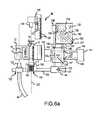
- FIGS. 6 a through 6 ecomprise diagrammatic plan views of the syringe-filling station on the apparatus embodiment of FIG. 5 wherein a sequence of component positions are shown that correspond to and illustrate sequential steps of cap removal, fluid filling, and cap replacement operation.
- FIGS. 7 a and 7 bcomprise isometric assembly and exploded views, respectively, of a labeling and filling apparatus of the embodiment corresponding with FIGS. 5 and 6 a-e;
- FIGS. 8 a - 8 dcomprise isometric views of the syringe-filling station of the apparatus embodiment of FIG. 7, wherein a sequence of component positions are shown that correspond with and illustrate the sequential steps of cap removal, fluid filling, and cap replacement operations.
- FIG. 9is a schematic elevation view of a labeling and filling apparatus according to another embodiment of this invention.
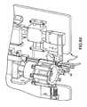
- FIG. 10is an isometric view of a syringe-filling station of the apparatus embodiment of FIG. 9.
- FIGS. 11 a - 11 hare flat, diagrammatic views of syringe handling operations at the filling-station of the apparatus embodiment of FIGS. 9 and 10.
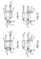
- FIGS. 12 a - 12 care isometric, end and cross-sectional views of a syringe cap employable in one embodiment of the syringe shown in FIG. 1 .
- FIGS. 13 a - 13 care isometric, end and cross-sectional views of a syringe cap employable in another embodiment of the syringe shown in FIG. 1 .
- FIG. 1A capped syringe S that has been labeled and filled according to one embodiment of this invention is shown in FIG. 1.
- a cap Ccovers and protects the sterility of the dispensing luer tip (concealed from view in FIG. 1 by the cap C). Since the barrel B of the syringe S is full in FIG. 1, the plunger P is extended longitudinally.
- a flap or substrate 10 for a label 12is provided by two strips of adhesive tape 14 , 16 , both of which are wrapped around and adhered to respectively opposite sides of the barrel B and adhered to each other in face-to-face relation in extensions 18 , 20 of the adhesive tape 14 , 16 that extend in diametrically opposite directions from the barrel B. It is preferred, but not necessary, that at least one of the adhesive tapes 14 , 16 be transparent so that the graduation marks G that are on most conventional syringes as well as the plunger piston (not shown) in FIG. 1) can be seen through the adhesive tape.
- the label 12is a printed sheet that has been adhered to the panel extension 20 of the substrate 10 .
- the labelcould also be provided in other ways according to this invention.
- the printed informationcould be printed directly on one or both of the adhesive tapes 14 , 16 .
- Such printing, if placed on a transparent tape 14 , 16would preferably not be enough to mask the graduation marks G.
- Another optioncould be to make one of the tapes, such as tape 14 opaque, perhaps with label information on it, but make the other tape 16 transparent so as not to mask or hide the graduation marks G.
- a sheet label similar to label 12could be sandwiched between the two adhesive tapes 14 , 16 .
- a significant feature of this inventionis having a plurality of sterile, capped syringes S mounted in spaced apart relation to each other in a band or belt 30 , as shown in FIG. 2, for handling the syringes S in automated preparation operations.
- belt 30may be employed for pulling the syringes S into and preferably at least partially through a labeling and/or filling apparatus and process, as will be described in more detail below.
- the band or belt 30can be made with the two elongated adhesive tapes 15 , 16 that were described above and which can be cut to separate the syringes S into individual syringes S with the label substrate 10 as shown in FIG. 1 and as will be described in more detail below.
- FIGS. 12 a - 12 c and FIGS. 13 a - 13 cillustrate alternate embodiments of caps C employable with syringes S of the type shown in FIGS. 1 and 2.
- the caps C of the two embodimentseach include a cylindrical outer member 500 for matingly engaging the outer flange provided at the dispensing end of the barrel B of the syringe S.
- a cylindrical inner member 502is also provided for matingly receiving the fluid port provided at the dispensing end of barrel B of syringe S.
- FIGS. 12 a - 12 c and FIGS. 13 a - 13 cillustrate alternate embodiments of caps C employable with syringes S of the type shown in FIGS. 1 and 2.
- the caps C of the two embodimentseach include a cylindrical outer member 500 for matingly engaging the outer flange provided at the dispensing end of the barrel B of the syringe S.
- a cylindrical inner member 502is also provided for matingly
- FIG. 13 a - 13 ca central pin-like inner member 504 is provided for mating insertion into the fluid port provided at the dispensing end of the barrel B of syringe S.
- internal locating legs 506are provided in the embodiment of FIG. 13 a - 13 c for retentively engaging the fluid port of barrel B.
- the embodiments of FIG. 12 a - 12 c and FIG. 13 a - 13 cboth provide for isolation of the contents of syringe S.
- FIG. 3one method and apparatus for mounting multiple syringes S into a band or belt 30 is shown in FIG. 3 .
- one tape stripe.g., tape strip 16
- tape strip 16is unwound from a roll 32 , as indicated by arrows 34 , 36
- itis threaded around the periphery 38 of a syringe mounting wheel 40 , which rotates as indicated by arrow 42 .
- a pair of rims(only one rim 44 of the pair can be seen in the elevation view of FIG.
- each of the rims 44has a plurality of notches 46 in equal, angularly spaced relation to each other around the periphery 38 .
- empty syringes Sare placed serially into the notches 46 , as indicated by arrows 48 , where they contact the adhesive side of the tape strip 16 .
- a contact plate 67may also be provided to insure engagement between tape strip 14 and syringes.
- press wheel 62that rotates, as indicated by arrow 64 , to press the tape strips 14 , 16 to each other between the syringes S.
- Press wheel 62may be provided for driven rotation, wherein such driven rotation effects rotation of the tape rolls 32 and 50 , as well as rotation of syringe mounting wheel 40 as the tape strips 14 , 16 are pulled around press wheel 62 with syringes S secured therebetween.
- a rotatable pressing block 63is juxtaposed to the press wheel 62 so that the tape strips 14 , 16 run between the press wheel 62 and the rotatable pressing block 63 .
- the pressing block 63may be configured to present a plurality of semicircular surfaces that are spaced to be in opposing relation to notches 60 . Thus, the press wheel 62 and the pressing block 63 cooperate to press and adhere the tape strips 14 , 16 tightly together and around the circumference of each syringe S.
- the pressing block 63is preferably yieldably biased by a spring-loaded pivot arm 65 or some other bias system to press the pressing block 63 toward the press wheel 62 .
- the belt 30 with the syringes S mounted thereinare fed as indicated by arrow 66 into a bin or bag 68 .
- the belt 30 with syringes Scould be fed directly into a labeling and/or filling apparatus, which will be described below.
- the syringes Sare positioned in the band or belt 30 in a common orientation, i.e., with luers of all the syringes S on the same side of the band 30 .
- the notches 46 in the wheel 40are spaced uniformly around the rim 44 , so the syringes S in the resulting band 30 are spaced equidistantly apart.
- the caps Ccan be placed on the syringes S either before, while, or after the syringes S are mounted in the band 30 .
- the band 30 of syringes Scan then be fan folded or rolled and placed in the plastic bag 68 , which can be closed and/or sealed to protect sterility.
- the package or bag 68 of banded syringes 30can then be sterilized by any of a variety of standard sterilization processes, for example by gamma radiation.
- the sterilized packages 68 of sterilized, banded syringes Susually in quantities of about 200 to 1,000 syringes S per package 68 , are shipped to users, such as hospitals or other health care institutions, who will label and/or fill and re-cap the syringes S for use within an acceptable time after filling.
- FIG. 4illustrates another method and apparatus embodiment for mounting multiple syringes S into a band or belt 30 .
- a syringe feed-wheel 203is driven synchronously with tape feed wheels 240 and 262 to form a band 30 of interconnected syringes S.
- tape feed wheels 240 and 262are driven to pull adhesive tapes 16 and 14 about idler wheels 215 and 258 from tape rolls 232 and 250 , respectively.
- Tensioning devices 211 and 215are provided to establish a desired amount of tension along tape strips 16 and 14 as they are fed to tape feed wheels 240 and 262 , respectively.
- a vibrating track 201is provided to advance syringes S for sequential loading into notches 205 of the syringe feed wheel 203 .
- the syringe feed-wheel 203is located immediately adjacent to the tape feed-wheel 240 so that notches 246 of the tape feed-wheel and notches 205 of the syringe feed-wheel 240 are disposed in opposing relation.
- a pneumatic position and tension control device 207is provided to enhance the interconnection between syringes S and tape 16 .
- Device 207includes a mount lever arm 207 a interconnected to the syringe feed-wheel 203 , and a pneumatic cylinder 207 b for locating the arm 207 a and syringe feed-wheel 203 as appropriate so that syringes S apply a predetermined, desired amount of force against tape 16 .
- FIG. 4 embodimentprovides for the interconnection of adhesive tape 14 to the other side of syringes S. More particularly, tape feed-wheel 262 is driven synchronously with and positioned relative to tape feed-wheel 240 so that notches 260 are in aligned relation with notches 246 to capture syringes S between adhesive tape strips 14 and 16 . Concomitantly, tape 14 is pressed about the syringes S to complete band 30 .
- a pneumatic position and tension control device 209is provided at the tape feed-wheel 262 .
- Device 209includes a mount lever arm 209 a and a pneumatic cylinder 209 b for locating the tape feed-wheel 262 as appropriate to establish the desired amount of force applied by syringes S to tape strip 16 .
- a band 30 of syringes Sis pulled from the bag 68 by a sprocket wheel or drum 72 and rotated to positions where the band 30 is cut to form the label substrates 10 (see FIG. 1 ), and, if the substrates are not already labeled, to attach labels 12 to the substrates 10 , and to remove the caps C, fill the syringes S with the desired medication, and replace the caps C.
- the userwill prepare a quantity of labels 12 and mount them to feed into a labeling station 80 .
- the labelscan be prepared in any suitable manner, for example, using a standard computer label printer, and the quantity of labels 12 prepared can correspond to the number of syringes S to be filled with medication that matches the labels 12 .
- the useralso prepares the liquid medication 91 in a container 92 , which the user connects to a suitable fluid control system, such as conventional peristaltic pump 93 or other suitable syringe filling, fluid metering, or handling system.
- the medicationwill be conveyed via a suitable tube 94 or other conduit to the syringe filling station 90 , which will be explained in more detail below.
- the volume of medication to be pumped into each syringe Scan be set and controlled in any of a variety of ways.
- the pump 93can be actuated to initiate a fill and deactuated when the syringe has been filled with the desired volume of medication, as will be described in more detail below.
- the sprocket drum 72has a plurality of notches 74 in equal, angularly-spaced relation to each other around the circumference of the drum 72 .
- the notches 74are large enough to receive and retain a syringe S, and they are spaced apart from each other the same distance as the spacing between the syringes S in the band 30 . Therefore, when at least one of the syringes S in the band 30 is positioned in an appropriate notch 74 , rotation of the drum 72 , as indicated by arrow 75 , will cause the band 30 to pull successive syringes S in the band 30 out of the bag 68 and into the labeling and filling apparatus 70 .
- Suitable guidesfor example, guides 76 , 77 , 78 , can be used to hold the syringes S in the notches 74 as the drum 72 rotates and carries the syringes S through the cutting station 100 , labeling station 80 , and filling station 90 .
- the drum 72can be driven to rotate, as indicated by arrow 75 , and to stop with syringes S positioned appropriately for the cutting, labeling, and filling operations at the respective stations 100 , 80 , 90 by any appropriate drive and control system as is well within the capability of persons skilled in the art, such as, for example, with a stepper motor (not shown) connected to appropriate motor control devices (not shown).
- a control panel (not shown) connected to the stepper motorcan be set up for use by an operator to either jog the drum 72 through incremental steps and/or jog the cutting station 100 , labeling station 80 , or filling station 90 through their respective operations or to initiate continuous automatic operation.
- an actuator 101drives a knife blade 102 as indicated by arrow 103 to cut and sever the band 30 to disconnect the syringes S from each other and to leave the resulting band segments or flaps connected to each syringe S to form individual label substrates 10 for each syringe S.
- the knife blade 102is preferably serrated and a slot 104 in the drum in alignment with the knife blade 102 facilitate sure, complete cuts.
- Any suitable actuator 101can be used, such as a rotary drive motor, solenoid, or the like.
- a sheath(not shown) can be provided to cover the blade 102 when it is not cutting.
- An optical or other sensor(not shown) can be positioned adjacent the drum 72 where the syringes S are first engaged by notches 74 to detect whether any syringes S have missing caps. A signal from the sensor in response to a missing cap could actuate and alarm and/or shut down the apparatus to prevent an uncapped syringe S from being labeled and filled.
- a labeler device 81For the syringe S that has advanced to the labeling station 80 , a labeler device 81 , moving as indicated by arrow 82 , affixes a label 12 to the substrate 10 .
- the labeler device 81can be any of a variety of known label apparatus that transfer labels 12 from a strip 83 to an object, or it could be some other device, such as printer apparatus that prints the label directly onto the flap substrate 10 , or some combination of such apparatus, as would be within the capabilities of persons skilled in the art once they understand the principles of this invention.
- An optical sensor(not shown) is used to detect whether a label has been affixed to the substrate 10 at the label station 80 .
- a microprocessor(not shown) can be used to keep count of labels properly affixed and/or activate an alarm and/or shut down the apparatus 70 if a label is not detected on a substrate where a label is supposed to be affixed.
- the cap C(not shown in FIG. 5) is removed by a cap handling apparatus 110 , then a liquid dispensing apparatus 120 is connected to the luer (not shown in FIG. 5) of the syringe S to dispense liquid medication into the syringe S, and the pump 93 (or other suitable liquid metering or control apparatus) is actuated to move the medication 91 from the container 92 into the syringe S.
- the pump 93or other suitable liquid metering or control apparatus
- the pump 93(or other suitable liquid metering or control apparatus) is deactuated. Then, the liquid dispensing apparatus 120 is disconnected from the syringe S, and the cap handling apparatus 100 is moved into position to replace the cap C (not shown in FIG. 5) onto the luer (not shown in FIG. 4) of the syringe S.
- the cap handling apparatus 110 and the liquid dispensing apparatus 120are mounted on a cammed shuttle 130 , which moves laterally in two axes, as indicated by arrow 131 in the plane of the paper and by arrow 132 perpendicular to the plane of the paper, to accomplish the cap removal, fill, and cap replacement functions described above.
- the syringes SAfter the syringes S leave the fill station 90 , they are allowed to drop individually out of the sprocket drum 72 and, for example, into a basket 150 or other receptacle. At this stage, the syringes S are labeled, filled, and ready for use, as shown in FIG. 1 .
- the cammed shuttle 130is driven by a motor, such as a stepper motor 133 , which rotates a slotted cam lever or crank arm 134 mounted on the drive shaft 135 of the motor 133 .
- a driver block 136has a slide pin or a cam roll (concealed from view) extending in one direction into the slotted race groove 137 of the cam lever or crank arm 134 and another cam follow pin or cam roll 138 extending in the opposite direction into a U-shaped cam slot 139 in a stationary cam block 140 . Therefore, as the stepper motor 133 rotates, for example as shown by arrow 141 in FIGS.
- the cam lever 134causes the cam follower pin or cam roll 138 extending from the driver block 136 to follow the U-shaped path of the cam slot 139 , which moves the two slide shafts 142 , 143 extending laterally from driver block 136 as well as the connecting block 144 at the distal ends of slide shafts 142 , 143 to move simultaneously in the same U-shaped motion pattern.
- the two slide shafts 142 , 143extend slidably through two holes 145 , 146 in a pillow block 147 , which is mounted slidably on two support rods 148 , 149 .
- the support rods 148 , 149are mounted in two stationary anchor blocks 150 , 151 and extend slidably through two holes 152 , 153 in pillow block 147 , which are perpendicular to, but vertically offset from, holes 145 , 146 .
- the stepper motor 133drives the driver block 136 through the U-shaped pattern of cam slot 139
- the pillow block 147slides laterally on support rods 148 , 149 as indicated by arrow 154
- the slide shafts 142 , 143slide longitudinally in pillow block 147 as indicated by arrow 155 .
- the connector block 144 and cammed shuttle 130also move both laterally and longitudinally as indicated by arrows 131 , 132 in the same U-shape pattern as the U-shaped cam slot 139 to remove the cap C from the syringe S, connect the syringe S to a nozzle 121 in the liquid dispensing apparatus 120 to fill the syringe S, disconnect the nozzle 121 , and replace the cap C, as will be described in more detail below.
- Suitable bushing or bearingscan be used to enhance the sliding movement of the shafts 142 , 143 and support rods 148 , 149 in the pillow block 147 .
- the drum 72has moved a syringe S to the filling station 90 , where it stops for the cap removal, fill, and cap replacement operation.
- the syringe Sis shown in FIG. 6 a positioned in a notch 74 with a label 12 affixed to the substrate 10 .
- the cap Cwas moved into a set of jaws 160 , which is aligned longitudinally with the syringe S when the slotted cam lever 134 is stopped in the position shown in FIG. 6 a and the drum 72 stops the syringe S in the filling station 90 .
- a cap gripper 161such as resilient spring steel, presses against the cap C in jaws 160 to capture and retain the cap C in the jaws 160 .
- optical sensors(not shown) or other suitable sensors and/or control devices or methods can be used to stop the drum 72 when the syringe S is positioned with the cap C captured in the jaws 160 as would be understood by persons skilled in the art once they understand the principles of this invention.
- the motor 133is actuated to rotate the slotted cam lever 134 as indicated by arrow 141 in FIG.
- the fill connector or nozzle 121is preferably mounted on the cammed shuttle 130 by a spring-loaded slide (not shown) or similar yieldable, resilient mounting to apply an appropriate, uniform force to the nozzle 121 as it is being forced by the cammed shuttle 130 onto the luer L of the syringe S.
- This motion to remove the cap C and place the fill connector or nozzle 121 on the syringe Scan be accomplished in approximately 250 milliseconds with this mechanism.
- the U-shaped cam slot 139provides a straight, longitudinal pull of the cap C in alignment with the longitudinal axis 123 of the syringe S and a corresponding straight, longitudinal push to attach the nozzle 121 to the luer L.
- the plunger P of the syringe Sis pushed outwardly by the liquid medication that is pumped into the syringe S.
- the flow of liquid medication into the syringe Sis stopped.
- the flowcan be measured and stopped in a variety of ways, such as flow meters, valves, known pump displacement, and the like, as would be within the knowledge and capabilities of persons skilled in the art once they understand the principles of this invention.
- a particularly novel and innovative way of controlling the fill volume according to this inventionis to use a sensor 124 to detect when the plunger P has been pushed out to a predetermined extent that corresponds to the fill volume desired, as illustrated in FIG.
- a myriad of sensorscould be used for this function, such as a capacitive proximity sensor, optical sensor, microswitch, and the like.
- a signal from the sensor 124can be used to shut off the flow of liquid medication into the syringe S.
- a suitable signal control circuitfor example, a microprocessor and/or relay, (not shown) to shut off the pump 93 or to close some control valve (not shown) is well within the capabilities of persons skilled in the art once they understand the principles of this invention.
- the sensor 124can be mounted on an adjustable base 125 with a scale 126 and pointer 127 to correlate adjustable physical position of the sensor with the desired fill volume.
- pump 93is a peristaltic pump, such as, for example, a model 099 Repeater Pump, manufactured by Baxa Corporation, of Englewood, Colo., which can be reversed momentarily to take the fluid pressure off the tubing 94 and syringe S to minimize, if not prevent, dripping of the liquid medication when the nozzle 121 is detached from the luer L. Then, the motor 133 is actuated to rotate the cam lever 132 in the opposite direction, as indicated by the arrow 159 in FIG.
- a peristaltic pumpsuch as, for example, a model 099 Repeater Pump, manufactured by Baxa Corporation, of Englewood, Colo.
- the cap handling apparatus 110can be mounted by a spring-loaded slide (not shown) or some other yieldable, resilient structure, if desired, to ensure a uniform pressure application to the cap C as it is being pushed by the cammed shuttle 130 back onto the syringe S.
- the fillis completed, and the drum 72 can be rotated again to move the cap C out of the jaws 160 and to move the next syringe S in the sequence into the jaws 160 for a repeat of the cap removal, fill, and cap replacement sequence described above on the next syringe S in the drum 72 .
- a sensorsuch as an optical sensor, is used to determine if the cap C is placed correctly back on the syringe S. If it is not placed correctly, the apparatus is stopped and/or an alarm is sounded in response to a signal from the sensor indicating that the cap C is not replaced.
- the drummoves the syringe to a point where hold down or guide tracks end, thereby freeing the syringe S to drop out of the drum 72 and into a chute (not shown) that guides the labeled, filled, and recapped syringe S into the holding basket 150 .
- the control system(not shown) can utilize signals from the sensors to record number of syringes S filled, program the number of doses desired and automatically stop when that number of syringes S are filled, record the number of doses actually pumped, record the number of doses or syringes in the basket 150 and keep track of rejected labels or syringes. Other functions can also be provided.
- the labeling and filling apparatus embodiment of FIG. 5 and FIG. 6 a - 6 eis further illustrated in a production implementation.
- the labeling and filling apparatus 70is shown in a compact table top arrangement that may be readily positioned in a sterile environment, e.g. within a sterile area having an appropriate exhaust hood.
- the apparatus 70includes a cutting station 100 , labeling station 80 and filling station 90 .
- the drum 72may be driven in a clockwise direction by a step motor 301 , wherein syringes S are positioned into the notches 74 for sequential feeding to the work stations 80 , 90 and 100 .
- an actuator 101in the form of a stepper motor may be utilized.
- the actuator 101may be controlled to turn a crank 303 having a cam follower 305 that is located in a slot 307 on a mount block 309 for cutting blade 102 .
- the block 309is supported on rails 311 , wherein driven rotation of the crank 303 effects linear travel of the cutting blade 102 towards and away from the drum 72 and a belt 30 with syringes S carried thereby.
- the operation of actuator 101may be timed in relation to the stepped movement of drum 72 so that belt 30 is cut into belt segments 10 of a consistent width by cutting blade 102 .
- the labeling device 81may include a stepper motor 315 to which a shaft 317 is interconnected for driven eccentric motion. That is, upon actuation stepper motor 315 may drive shaft 317 through an arc from a first position to a second position.
- the first positionmay be as illustrated in FIGS. 7 a and 7 b , wherein the labeling device 81 is located in a down position for label placement.
- shaft 317Upon eccentric motion of the shaft 317 to a second position, shaft 317 will engage the labeling device 81 causing the cantilevered end thereof to cock upwards about a stationary shaft 319 .
- the operation of stepper motor 315is timed in relation to the stepped movement of drum 72 to affect label placement on the belt segments 10 between adjacent syringes S.
- FIGS. 8 a - 8 doperation of the filling station 80 shown in FIGS. 7 a and 7 b will be further described.
- a syringe Shas advanced to the filling station 90 with a cap C inserted into cap handling apparatus 110 .
- syringe Shas an interconnected belt segment on flap 10 with a label 12 adhered thereto.
- filling station 90has retracted away from drum 72 so as to remove cap C from the dispensing end of the syringe S.
- retractionis achieved by activating stepper motor 133 to rotate cam lever 134 , thereby causing driver block 136 , slide shafts 142 , 143 , connecting block 144 and shuttle 130 to move along a first straight leg portion of U-shaped motion pattern.
- FIG. 8 cshows the filling station 90 immediately after cam lever 134 has moved through the curved portion of the U-shaped motion pattern.
- the nozzle 121 of the liquid dispensing apparatus 120is aligned with the dispensing end of the syringe S.
- FIG. 8 dfurther movement of the filling station 90 along the second straight leg portion of the U-shaped motion pattern causes the liquid dispensing apparatus 120 to linearly advance towards syringe S, wherein the nozzle 121 engages and fluidly interconnects with the dispensing end of the syringe S.
- filling station 90may be controlled so that fluid is injected through nozzle 121 into the syringe S As further shown in FIG. 8 d , fluid has filled the syringe S to displace the plunger P into contact with the sensor 124 . At this point, a sensor signal is transmitted to terminate the filling of syringe S. Thereafter, stepper motor 133 may again rotate cam lever 134 through the U-shaped motion pattern to reposition cap C back onto the dispensing end of the syringe S.
- FIGS. 9, 10 and 11 a - 11 fillustrate an alternate embodiment.
- a drum 472is driven in a counter-clock wise direction, wherein a band 430 of syringes S pulled in series into the notches 474 for preparation operations.
- the band 430is suspended from the drum 472 to facilitate aligned, side-by-side positioning of the syringes S in notches 474 .
- the syringes Sare sequentially advanced through filling station 490 , labeling station 480 and cutting station 400 . Thereafter, the separated syringes S may be directed into a container (not shown) via a chute 500 .
- labeling station 480 and cutting station 400may be analogous to the operations of the labeling station 80 and cutting station 100 described above in relation to FIG. 5 and FIGS. 6 a - 6 b .
- the embodiment shown in FIGS. 9, 10 and 11 a - 11 hmay implement a different approach at filling station 490 .
- filling station 490includes a cap handling apparatus 410 and liquid dispensing apparatus 420 .
- liquid dispensing apparatus 420is interconnectable to a reservoir (not shown) containing a fluid for filling syringes S.
- both the cap handling apparatus 41 and liquid dispensing apparatus 420are mounted on a common support member 430 .
- Support member 430may be interconnected to a stepper motor (not shown) acutatable to affect linear travel of the cap handling apparatus 410 and liquid dispensing apparatus 420 towards and away from the drum 472 .
- a stepper motornot shown
- Such linear travel, together with the rotation of drum 472are the only required motions for cap removal, filling and cap replacement.
- FIGS. 11 a - 11 hare flat, diagrammatic views of filling station 490 from a rearward perspective relative to the isometric front view shown in FIG. 10 .
- the filling station 490 shown in FIGS. 11 a - 11 hfurther includes a syringe flange retention track 492 and a plunger flange retention member 494 .
- the plunger flange retention number 494is selectively retractable relative to retention track 492 so that fluid may be drawn from liquid dispensing apparatus 420 to fill syringes S.
- liquid dispensing apparatus 420may include a valve to control the passage/stoppage of fluid therethrough.
- such valvemay comprise an actuatable roller.
- a syringe Sis shown in the first location I shown in FIG. 9 wherein Cap C has been inserted in the cap handling apparatus 410 for retention thereby. Concomitantly, a flange on syringe S has been inserted and advanced within the retention track 492 .
- cap handling apparatus 410has been retracted from the syringe S with cap C retained thereby. As will be appreciated, such retraction may be affected via linear driven travel of the support member 430 shown in FIG. 10 .
- FIG. 11 cshows the syringe S moved to the location II shown in FIG. 9 . More particularly, drum 472 may be rotated clockwise to affect such positioning, wherein the liquid dispensing apparatus 420 is aligned with the dispensing end of the syringe S. Then, liquid dispensing apparatus 420 may be advanced into engagement with the dispensing end of syringe S as shown in FIG. 11 d . Again, such linear travel may be affected via movement of support member 430 . Of note, both FIGS. 11 c and 11 d show the plunger P being positioned in the retention member 494 .
- retention member 494may be provided for driven retraction away from syringe S (e.g. via an unshown stepper motor), with the valve of liquid dispensing apparatus 420 opened so as to draw fluid through liquid dispensing apparatus 420 into the syringe S.
- the amount, or length, of retraction of retention member 494may be precisely controlled to achieve a preset filling volume.
- the valve of liquid dispensing apparatus 420may be closed.
- the rollermay be positioned to pinch off a fluid conduit to back up the fluid a desired amount, thereby bringing the fluid pressure slightly below atmospheric pressure.
- the liquid dispensing apparatus 420may be withdrawn from the dispensing end of the syringe S as shown in FIG. 11 f . Again, such linear travel may be affected by controlled retraction of the support member 430 .
- syringe Smay return to location I via counter-clockwise rotation of drum 472 , as shown in FIG. 11 g .
- cap Cmay be replaced onto the dispensing end of the syringe S via advancement of the cap handling apparatus 410 on support member 430 .
- the syringe Smay then be advanced for further operations at the labeling station 480 and cutting station 400 shown in FIG. 9 .
Landscapes
- Engineering & Computer Science (AREA)
- Mechanical Engineering (AREA)
- Health & Medical Sciences (AREA)
- Life Sciences & Earth Sciences (AREA)
- General Health & Medical Sciences (AREA)
- Biomedical Technology (AREA)
- Heart & Thoracic Surgery (AREA)
- Hematology (AREA)
- Vascular Medicine (AREA)
- Animal Behavior & Ethology (AREA)
- Anesthesiology (AREA)
- Public Health (AREA)
- Veterinary Medicine (AREA)
- Physics & Mathematics (AREA)
- General Physics & Mathematics (AREA)
- Theoretical Computer Science (AREA)
- Labeling Devices (AREA)
- Infusion, Injection, And Reservoir Apparatuses (AREA)
- Basic Packing Technique (AREA)
Abstract
Description
Claims (36)
Priority Applications (10)
| Application Number | Priority Date | Filing Date | Title |
|---|---|---|---|
| US09/928,007US6813868B2 (en) | 2000-08-10 | 2001-08-10 | Method, system, and apparatus for handling, labeling, filling and capping syringes |
| US10/630,059US6976349B2 (en) | 2000-08-10 | 2003-07-30 | Method for filling and capping syringes |
| US10/727,097US6957522B2 (en) | 2001-08-10 | 2003-12-03 | Method and system for labeling syringe bodies |
| US10/727,142US6915619B2 (en) | 2001-08-10 | 2003-12-03 | Method for handling syringe bodies |
| US10/864,610US20040221548A1 (en) | 2000-08-10 | 2004-06-09 | Method, system, and apparatus for handling, labeling, filling, and capping syringes |
| US11/361,326US7207152B2 (en) | 2000-08-10 | 2006-02-24 | Method for handling, labeling and filling syringes |
| US11/365,799US7392638B2 (en) | 2000-08-10 | 2006-02-28 | Method, system, and apparatus for handling, labeling, filling, and capping syringes with improved cap |
| US11/427,740US7469518B2 (en) | 2000-08-10 | 2006-06-29 | Method for handling and labeling syringes |
| US11/427,751US7478513B2 (en) | 2000-08-10 | 2006-06-29 | Method for handling and labeling syringes |
| US12/120,350US7631475B2 (en) | 2000-08-10 | 2008-05-14 | Method for filling and capping syringes |
Applications Claiming Priority (2)
| Application Number | Priority Date | Filing Date | Title |
|---|---|---|---|
| US22413600P | 2000-08-10 | 2000-08-10 | |
| US09/928,007US6813868B2 (en) | 2000-08-10 | 2001-08-10 | Method, system, and apparatus for handling, labeling, filling and capping syringes |
Related Child Applications (4)
| Application Number | Title | Priority Date | Filing Date |
|---|---|---|---|
| US10/630,059DivisionUS6976349B2 (en) | 2000-08-10 | 2003-07-30 | Method for filling and capping syringes |
| US10/727,142ContinuationUS6915619B2 (en) | 2001-08-10 | 2003-12-03 | Method for handling syringe bodies |
| US10/727,097ContinuationUS6957522B2 (en) | 2001-08-10 | 2003-12-03 | Method and system for labeling syringe bodies |
| US10/864,610ContinuationUS20040221548A1 (en) | 2000-08-10 | 2004-06-09 | Method, system, and apparatus for handling, labeling, filling, and capping syringes |
Publications (2)
| Publication Number | Publication Date |
|---|---|
| US20020020459A1 US20020020459A1 (en) | 2002-02-21 |
| US6813868B2true US6813868B2 (en) | 2004-11-09 |
Family
ID=22839401
Family Applications (7)
| Application Number | Title | Priority Date | Filing Date |
|---|---|---|---|
| US09/928,007Expired - Fee RelatedUS6813868B2 (en) | 2000-08-10 | 2001-08-10 | Method, system, and apparatus for handling, labeling, filling and capping syringes |
| US10/630,059Expired - Fee RelatedUS6976349B2 (en) | 2000-08-10 | 2003-07-30 | Method for filling and capping syringes |
| US10/864,610AbandonedUS20040221548A1 (en) | 2000-08-10 | 2004-06-09 | Method, system, and apparatus for handling, labeling, filling, and capping syringes |
| US11/361,326Expired - LifetimeUS7207152B2 (en) | 2000-08-10 | 2006-02-24 | Method for handling, labeling and filling syringes |
| US11/427,751Expired - Fee RelatedUS7478513B2 (en) | 2000-08-10 | 2006-06-29 | Method for handling and labeling syringes |
| US11/427,740Expired - Fee RelatedUS7469518B2 (en) | 2000-08-10 | 2006-06-29 | Method for handling and labeling syringes |
| US12/120,350Expired - LifetimeUS7631475B2 (en) | 2000-08-10 | 2008-05-14 | Method for filling and capping syringes |
Family Applications After (6)
| Application Number | Title | Priority Date | Filing Date |
|---|---|---|---|
| US10/630,059Expired - Fee RelatedUS6976349B2 (en) | 2000-08-10 | 2003-07-30 | Method for filling and capping syringes |
| US10/864,610AbandonedUS20040221548A1 (en) | 2000-08-10 | 2004-06-09 | Method, system, and apparatus for handling, labeling, filling, and capping syringes |
| US11/361,326Expired - LifetimeUS7207152B2 (en) | 2000-08-10 | 2006-02-24 | Method for handling, labeling and filling syringes |
| US11/427,751Expired - Fee RelatedUS7478513B2 (en) | 2000-08-10 | 2006-06-29 | Method for handling and labeling syringes |
| US11/427,740Expired - Fee RelatedUS7469518B2 (en) | 2000-08-10 | 2006-06-29 | Method for handling and labeling syringes |
| US12/120,350Expired - LifetimeUS7631475B2 (en) | 2000-08-10 | 2008-05-14 | Method for filling and capping syringes |
Country Status (5)
| Country | Link |
|---|---|
| US (7) | US6813868B2 (en) |
| EP (1) | EP1313644B1 (en) |
| AU (1) | AU2001290528A1 (en) |
| DE (1) | DE60131986T2 (en) |
| WO (1) | WO2002011787A2 (en) |
Cited By (65)
| Publication number | Priority date | Publication date | Assignee | Title |
|---|---|---|---|---|
| US20040182475A1 (en)* | 2003-02-15 | 2004-09-23 | Arzneimittel Gmbh Apotheker Vetter & Co. Ravensburg | System for monitoring production of prefilled syringes |
| US20040250877A1 (en)* | 2001-11-15 | 2004-12-16 | Osborne Joel A. | Syringe bandoleer with control feature |
| US20050045242A1 (en)* | 2002-12-03 | 2005-03-03 | Osborne Joel A. | Automated means of storing, dispensing and orienting injectable drug vials for a robotic application |
| WO2004050038A3 (en)* | 2002-12-03 | 2006-04-13 | Forhealth Technologies Inc | Automated syringe preparation and automated transfer of medication thereto and safety features associated therewith |
| US20060243804A1 (en)* | 2003-10-03 | 2006-11-02 | Novo Nordisk A/S | Container comprising code information elements |
| US20060260276A1 (en)* | 2000-08-10 | 2006-11-23 | Baldwin Brian E | Method for handling and labeling syringes |
| US20070125442A1 (en)* | 2002-12-03 | 2007-06-07 | Forhealth Technologies, Inc. | Automated drug preparation apparatus including automated drug reconstitution |
| US20080035234A1 (en)* | 2006-08-10 | 2008-02-14 | Forhealth Technologies, Inc. | Automated system and process for filling drug delivery devices of multiple sizes |
| US20080051937A1 (en)* | 2006-08-23 | 2008-02-28 | Forhealth Technologies, Inc. | Automated drug delivery bag filling system |
| US20080169045A1 (en)* | 2006-10-31 | 2008-07-17 | Forhealth Technologies, Inc. | Automated drug preparation apparatus including serial dilution functionality |
| US20080276504A1 (en)* | 2007-05-11 | 2008-11-13 | Cloninger Timothy N | Multi-flag label and method of use |
| US7601966B2 (en) | 2006-06-28 | 2009-10-13 | Spectrum Dynamics Llc | Imaging techniques for reducing blind spots |
| US7614545B2 (en)* | 2003-03-24 | 2009-11-10 | Novo Nordisk A/S | Electronic marking of a medication cartridge |
| US7621456B2 (en) | 2000-08-10 | 2009-11-24 | Novo Nordisk A/S | Support for a cartridge for transferring an electronically readable item of information from the cartridge to an electronic circuit |
| US7814731B2 (en) | 2006-10-20 | 2010-10-19 | Forhealth Technologies, Inc. | Automated drug preparation apparatus including a bluetooth communications network |
| US7900658B2 (en) | 2006-10-20 | 2011-03-08 | Fht, Inc. | Automated drug preparation apparatus including drug vial handling, venting, cannula positioning functionality |
| US7922096B2 (en) | 2000-08-10 | 2011-04-12 | Novo Nordisk A/S | Support for a cartridge for transferring an electronically readable item of information from the cartridge to an electronic circuit |
| US8037659B2 (en) | 2006-10-20 | 2011-10-18 | Forhealth Technologies, Inc. | Automated drug preparation apparatus including syringe loading, preparation and filling |
| US8049519B2 (en) | 2006-04-26 | 2011-11-01 | Novo Nordisk A/S | Contact free absolute position determination of a moving element in a medication delivery device |
| US8197449B2 (en) | 2005-05-10 | 2012-06-12 | Novo Nordisk A/S | Injection device comprising an optical sensor |
| US8286671B1 (en) | 2011-03-23 | 2012-10-16 | Saverio Roberto Strangis | Automated syringe filler and loading apparatus |
| US8348904B2 (en) | 2007-03-21 | 2013-01-08 | Novo Nordisk A/S | Medical delivery system having container recognition and container for use with the medical delivery system |
| US8353869B2 (en) | 2010-11-02 | 2013-01-15 | Baxa Corporation | Anti-tampering apparatus and method for drug delivery devices |
| US8423125B2 (en) | 2004-11-09 | 2013-04-16 | Spectrum Dynamics Llc | Radioimaging |
| US20130105521A1 (en)* | 2009-10-23 | 2013-05-02 | Nestec S.A. | Method and device for aseptically dispensing multiple portions of a fluid |
| US8445851B2 (en) | 2004-11-09 | 2013-05-21 | Spectrum Dynamics Llc | Radioimaging |
| US8489176B1 (en) | 2000-08-21 | 2013-07-16 | Spectrum Dynamics Llc | Radioactive emission detector equipped with a position tracking system and utilization thereof with medical systems and in medical procedures |
| US8492725B2 (en) | 2009-07-29 | 2013-07-23 | Biosensors International Group Ltd. | Method and system of optimized volumetric imaging |
| US8521253B2 (en) | 2007-10-29 | 2013-08-27 | Spectrum Dynamics Llc | Prostate imaging |
| US8522832B2 (en) | 2009-07-29 | 2013-09-03 | Icu Medical, Inc. | Fluid transfer devices and methods of use |
| US8565860B2 (en) | 2000-08-21 | 2013-10-22 | Biosensors International Group, Ltd. | Radioactive emission detector equipped with a position tracking system |
| US8571881B2 (en) | 2004-11-09 | 2013-10-29 | Spectrum Dynamics, Llc | Radiopharmaceutical dispensing, administration, and imaging |
| US8606349B2 (en) | 2004-11-09 | 2013-12-10 | Biosensors International Group, Ltd. | Radioimaging using low dose isotope |
| US8610075B2 (en) | 2006-11-13 | 2013-12-17 | Biosensors International Group Ltd. | Radioimaging applications of and novel formulations of teboroxime |
| US8608079B2 (en) | 2006-03-20 | 2013-12-17 | Novo Nordisk A/S | Contact free reading of cartridge identification codes |
| US8615405B2 (en) | 2004-11-09 | 2013-12-24 | Biosensors International Group, Ltd. | Imaging system customization using data from radiopharmaceutical-associated data carrier |
| US8620046B2 (en) | 2000-08-21 | 2013-12-31 | Biosensors International Group, Ltd. | Radioactive-emission-measurement optimization to specific body structures |
| US8638108B2 (en) | 2005-09-22 | 2014-01-28 | Novo Nordisk A/S | Device and method for contact free absolute position determination |
| US8644910B2 (en) | 2005-07-19 | 2014-02-04 | Biosensors International Group, Ltd. | Imaging protocols |
| US8676292B2 (en) | 2004-01-13 | 2014-03-18 | Biosensors International Group, Ltd. | Multi-dimensional image reconstruction |
| US20140131534A1 (en)* | 2012-11-09 | 2014-05-15 | Ookuma Electronic Co., Ltd. | Information reader of injection container |
| US8837793B2 (en) | 2005-07-19 | 2014-09-16 | Biosensors International Group, Ltd. | Reconstruction stabilizer and active vision |
| US8864725B2 (en) | 2009-03-17 | 2014-10-21 | Baxter Corporation Englewood | Hazardous drug handling system, apparatus and method |
| US8894974B2 (en) | 2006-05-11 | 2014-11-25 | Spectrum Dynamics Llc | Radiopharmaceuticals for diagnosis and therapy |
| US8909325B2 (en) | 2000-08-21 | 2014-12-09 | Biosensors International Group, Ltd. | Radioactive emission detector equipped with a position tracking system and utilization thereof with medical systems and in medical procedures |
| US20140360594A1 (en)* | 2007-07-05 | 2014-12-11 | Baxter International Inc. | Medical fluid machine with supply autoconnection |
| US8994382B2 (en) | 2006-04-12 | 2015-03-31 | Novo Nordisk A/S | Absolute position determination of movably mounted member in medication delivery device |
| US9040016B2 (en) | 2004-01-13 | 2015-05-26 | Biosensors International Group, Ltd. | Diagnostic kit and methods for radioimaging myocardial perfusion |
| US9186465B2 (en) | 2008-11-06 | 2015-11-17 | Novo Nordisk A/S | Electronically assisted drug delivery device |
| US9275451B2 (en) | 2006-12-20 | 2016-03-01 | Biosensors International Group, Ltd. | Method, a system, and an apparatus for using and processing multidimensional data |
| US9316743B2 (en) | 2004-11-09 | 2016-04-19 | Biosensors International Group, Ltd. | System and method for radioactive emission measurement |
| US9470801B2 (en) | 2004-01-13 | 2016-10-18 | Spectrum Dynamics Llc | Gating with anatomically varying durations |
| US9849236B2 (en) | 2013-11-25 | 2017-12-26 | Icu Medical, Inc. | Methods and systems for filling IV bags with therapeutic fluid |
| US9883987B2 (en) | 2011-12-22 | 2018-02-06 | Icu Medical, Inc. | Fluid transfer devices and methods of use |
| US9943274B2 (en) | 2004-11-09 | 2018-04-17 | Spectrum Dynamics Medical Limited | Radioimaging using low dose isotope |
| US9950117B2 (en) | 2009-02-13 | 2018-04-24 | Novo Nordisk A/S | Medical device and cartridge |
| USD837983S1 (en) | 2015-12-04 | 2019-01-08 | Icu Medical, Inc. | Fluid transfer device |
| US10293091B2 (en)* | 2007-07-05 | 2019-05-21 | Baxter International Inc. | Dialysis system having an autoconnection mechanism |
| USD851745S1 (en) | 2016-07-19 | 2019-06-18 | Icu Medical, Inc. | Medical fluid transfer system |
| US10589022B2 (en) | 2015-12-30 | 2020-03-17 | Baxter Corporation Englewood | Syringe plunger positioning apparatus and method |
| US10688021B2 (en) | 2002-12-03 | 2020-06-23 | Baxter Corporation Englewood | Automated drug preparation apparatus including automated drug reconstitution |
| US10964075B2 (en) | 2004-01-13 | 2021-03-30 | Spectrum Dynamics Llc | Gating with anatomically varying durations |
| US11020541B2 (en) | 2016-07-25 | 2021-06-01 | Icu Medical, Inc. | Systems, methods, and components for trapping air bubbles in medical fluid transfer modules and systems |
| US11590057B2 (en) | 2020-04-03 | 2023-02-28 | Icu Medical, Inc. | Systems, methods, and components for transferring medical fluids |
| US20250009603A1 (en)* | 2023-07-03 | 2025-01-09 | Carefusion 303, Inc. | Semi-automated compounding platform |
Families Citing this family (105)
| Publication number | Priority date | Publication date | Assignee | Title |
|---|---|---|---|---|
| US6604903B2 (en) | 2001-11-30 | 2003-08-12 | Forhealth Technologies, Inc. | Automated drug vial safety cap removal |
| US7762301B2 (en)* | 2002-09-16 | 2010-07-27 | CSAT Gesellschaft für Computer-Systeme und Automalions-Technik mbH | Device for the precise positional joining of two material webs |
| US10966421B2 (en) | 2002-10-16 | 2021-04-06 | Streck, Inc. | Method and device for collecting and preserving cells for analysis |
| US6877530B2 (en) | 2002-12-03 | 2005-04-12 | Forhealth Technologies, Inc. | Automated means for withdrawing a syringe plunger |
| US6915823B2 (en) | 2002-12-03 | 2005-07-12 | Forhealth Technologies, Inc. | Automated apparatus and process for reconstitution and delivery of medication to an automated syringe preparation apparatus |
| US7017622B2 (en)* | 2002-12-03 | 2006-03-28 | Forhealth Technologies, Inc. | Automated means for removing, parking and replacing a syringe tip cap from a syringe |
| US6991002B2 (en)* | 2002-12-03 | 2006-01-31 | Forhealth Technologies, Inc. | Tamper evident syringe tip cap and automated method for preparing tamper-evident syringes |
| FR2848534B1 (en)* | 2002-12-11 | 2005-07-08 | Valois Sas | FLUID PRODUCT DISPENSING ASSEMBLY |
| US6986234B2 (en)* | 2003-06-27 | 2006-01-17 | Forhealth Technologies, Inc. | System and method for bandoliering syringes |
| US7007443B2 (en)* | 2003-06-27 | 2006-03-07 | Forhealth Technologies, Inc. | System and method for bandoliering syringes |
| WO2005017883A2 (en)* | 2003-08-15 | 2005-02-24 | Integrated Healthcare Systems, Inc. | Method and apparatus for delivering barcode-to-dose labels |
| US20050140135A1 (en)* | 2003-12-05 | 2005-06-30 | Miller Richard T. | Label with clear adhesive portion |
| US7163035B2 (en)* | 2004-05-13 | 2007-01-16 | Forhealth Technologies, Inc. | Automated use of a vision system to detect foreign matter in reconstituted drugs before transfer to a syringe |
| US7128105B2 (en)* | 2004-04-07 | 2006-10-31 | Forhealth Technologies, Inc. | Device for reconstituting a drug vial and transferring the contents to a syringe in an automated matter |
| US7343943B2 (en)* | 2004-05-13 | 2008-03-18 | Forhealth Technologies, Inc. | Medication dose underfill detection system and application in an automated syringe preparing system |
| US7017623B2 (en)* | 2004-06-21 | 2006-03-28 | Forhealth Technologies, Inc. | Automated use of a vision system to unroll a label to capture and process drug identifying indicia present on the label |
| EP1831076B1 (en)* | 2004-09-02 | 2013-11-06 | Richard Tomalesky | Apparatus and method of sterile filling of containers |
| US7398802B2 (en)* | 2004-09-02 | 2008-07-15 | Baker James W | System for dispensing biological fluids |
| WO2006069361A2 (en) | 2004-12-22 | 2006-06-29 | Intelligent Hospital Systems Ltd. | Automated pharmacy admixture system (apas) |
| US7783383B2 (en)* | 2004-12-22 | 2010-08-24 | Intelligent Hospital Systems Ltd. | Automated pharmacy admixture system (APAS) |
| US7499581B2 (en)* | 2005-02-10 | 2009-03-03 | Forhealth Technologies, Inc. | Vision system to calculate a fluid volume in a container |
| US8374887B1 (en) | 2005-02-11 | 2013-02-12 | Emily H. Alexander | System and method for remotely supervising and verifying pharmacy functions |
| US7931859B2 (en)* | 2005-12-22 | 2011-04-26 | Intelligent Hospital Systems Ltd. | Ultraviolet sanitization in pharmacy environments |
| US7571747B2 (en)* | 2006-01-09 | 2009-08-11 | Spitz Gregory A | Syringe filling apparatus |
| ITFI20060219A1 (en)* | 2006-09-07 | 2008-03-08 | Leporati Celestina | APPARATUS AND METHOD FOR THE COLLECTION, TREATMENT AND AUTOMATIC PACKAGING OF SURGICAL IRONS AFTER USE |
| CA2668981C (en) | 2006-11-09 | 2016-10-04 | Intelligent Hospital Systems Ltd. | Control of fluid transfer operations |
| US7748199B2 (en) | 2006-11-28 | 2010-07-06 | Align Technology, Inc. | System and method for packaging of mass-fabricated custom items |
| USD592303S1 (en)* | 2006-11-30 | 2009-05-12 | Medical Components, Inc. | Catheter information clip |
| US20080171981A1 (en)* | 2007-01-11 | 2008-07-17 | Forhealth Technologies, Inc. | Tamper evident cap for a drug delivery device |
| ITBO20070079A1 (en) | 2007-02-14 | 2008-08-15 | Co Ri M A S R L | DISPOSABLE CONTAINER AND METHOD FOR LABELING. |
| US8271138B2 (en)* | 2007-09-12 | 2012-09-18 | Intelligent Hospital Systems Ltd. | Gripper device |
| NZ562037A (en)* | 2007-09-27 | 2010-08-27 | Merial Ltd | removal of cap of container such as syringe attained by cap projection being received in removal device attachable to belt or wrist |
| US8225824B2 (en)* | 2007-11-16 | 2012-07-24 | Intelligent Hospital Systems, Ltd. | Method and apparatus for automated fluid transfer operations |
| US8763651B2 (en)* | 2008-02-01 | 2014-07-01 | Rescue Dose Ltd. | Dosage dispensing device |
| US20100038273A1 (en)* | 2008-08-13 | 2010-02-18 | Johnson David T | Sleeve, system and/or method for concealing a surface of a container |
| IT1391065B1 (en)* | 2008-10-17 | 2011-11-18 | Co Ri M A S R L | MACHINE FOR FILLING VIALS |
| DE102008054238A1 (en)* | 2008-10-31 | 2010-05-06 | Krones Ag | Method for checking the function of a monitoring device of an automatic labeling machine |
| WO2010078194A1 (en)* | 2008-12-30 | 2010-07-08 | Streck, Inc. | Method for screening blood using a preservative that may be in a substantially solid state form |
| US11634747B2 (en) | 2009-01-21 | 2023-04-25 | Streck Llc | Preservation of fetal nucleic acids in maternal plasma |
| EP3778919A1 (en) | 2009-02-18 | 2021-02-17 | Streck Inc. | Preservation of cell-free nucleic acids |
| US8386070B2 (en)* | 2009-03-18 | 2013-02-26 | Intelligent Hospital Systems, Ltd | Automated pharmacy admixture system |
| US20100277323A1 (en)* | 2009-05-04 | 2010-11-04 | Display Technologies, Inc. | Anti-theft tag for an elongate member |
| IT1394366B1 (en)* | 2009-05-26 | 2012-06-15 | Mg 2 Srl | METHOD AND EQUIPMENT FOR THE SCREWING OF SYRINGE RODS |
| USD637235S1 (en) | 2009-10-14 | 2011-05-03 | Streck, Inc. | Blood sample tube label |
| EP2499259B1 (en)* | 2009-11-09 | 2016-04-06 | Streck Inc. | Stabilization of rna in and extracting from intact cells within a blood sample |
| US20110138749A1 (en)* | 2009-12-15 | 2011-06-16 | Donald Chow | System and method for manufacturing a tubular container with opening and closing means |
| JP2013517081A (en)* | 2010-01-19 | 2013-05-16 | ケンブリッジ・エンタープライズ・リミテッド | Apparatus and method |
| US11881307B2 (en) | 2012-05-24 | 2024-01-23 | Deka Products Limited Partnership | System, method, and apparatus for electronic patient care |
| US10453157B2 (en) | 2010-01-22 | 2019-10-22 | Deka Products Limited Partnership | System, method, and apparatus for electronic patient care |
| US20110313789A1 (en) | 2010-01-22 | 2011-12-22 | Deka Products Limited Partnership | Electronic patient monitoring system |
| US11164672B2 (en) | 2010-01-22 | 2021-11-02 | Deka Products Limited Partnership | System and apparatus for electronic patient care |
| US9789247B2 (en) | 2011-12-21 | 2017-10-17 | Deka Products Limited Partnership | Syringe pump, and related method and system |
| US10911515B2 (en) | 2012-05-24 | 2021-02-02 | Deka Products Limited Partnership | System, method, and apparatus for electronic patient care |
| US9295778B2 (en) | 2011-12-21 | 2016-03-29 | Deka Products Limited Partnership | Syringe pump |
| US9744300B2 (en) | 2011-12-21 | 2017-08-29 | Deka Products Limited Partnership | Syringe pump and related method |
| US11210611B2 (en) | 2011-12-21 | 2021-12-28 | Deka Products Limited Partnership | System, method, and apparatus for electronic patient care |
| US11244745B2 (en) | 2010-01-22 | 2022-02-08 | Deka Products Limited Partnership | Computer-implemented method, system, and apparatus for electronic patient care |
| US10242159B2 (en) | 2010-01-22 | 2019-03-26 | Deka Products Limited Partnership | System and apparatus for electronic patient care |
| FR2955563B1 (en)* | 2010-01-26 | 2013-09-06 | Spc France | MACHINE FOR FILLING A PLURALITY OF CONTAINERS, SYSTEM INCLUDING SUCH A MACHINE AND PROCESS FOR PRODUCING THE SAME |
| US9930297B2 (en) | 2010-04-30 | 2018-03-27 | Becton, Dickinson And Company | System and method for acquiring images of medication preparations |
| US20110315269A1 (en)* | 2010-06-25 | 2011-12-29 | Bioject, Inc. | High workload injection system |
| US10695490B2 (en) | 2010-09-17 | 2020-06-30 | Nicholas J Perazzo | Syringe filling and packaging system for hospital pharmacies |
| US9466088B2 (en) | 2010-09-17 | 2016-10-11 | National Instrument, Llc | Automated oral syringe packaging system for hospital pharmacies |
| US9033006B2 (en) | 2010-09-17 | 2015-05-19 | Nicholas J. Perazzo | Oral syringe packaging system for hospital pharmacies |
| JP5417353B2 (en)* | 2011-01-31 | 2014-02-12 | 株式会社日立ハイテクノロジーズ | Automatic analysis system |
| US8807177B2 (en)* | 2011-05-18 | 2014-08-19 | Saverio Roberto Strangis | Automated syringe filler and loading apparatus |
| JP2013034567A (en)* | 2011-08-05 | 2013-02-21 | Daikyo Seiko Ltd | Plastic-made nozzle cap |
| US11217340B2 (en) | 2011-12-21 | 2022-01-04 | Deka Products Limited Partnership | Syringe pump having a pressure sensor assembly |
| US12131826B2 (en) | 2011-12-21 | 2024-10-29 | Deka Products Limited Partnership | Syringe pump and related method |
| US10722645B2 (en) | 2011-12-21 | 2020-07-28 | Deka Products Limited Partnership | Syringe pump, and related method and system |
| US12196364B2 (en) | 2011-12-21 | 2025-01-14 | DEKA Research Products Limited Partnership | System, method, and apparatus for clamping |
| US10563681B2 (en) | 2011-12-21 | 2020-02-18 | Deka Products Limited Partnership | System, method, and apparatus for clamping |
| US20130320625A1 (en)* | 2012-05-30 | 2013-12-05 | Micromatic Llc | Insertion apparatus |
| WO2014097366A1 (en)* | 2012-12-17 | 2014-06-26 | テルモ株式会社 | Syringe with hanging tag |
| WO2014138607A1 (en) | 2013-03-07 | 2014-09-12 | National Instrument, L.L.C. | Automated oral syringe packaging system for hospital pharmacies |
| US8875882B1 (en) | 2013-04-16 | 2014-11-04 | Maan G. Salloum | Holder and disposal device for hypodermic needles |
| EP3024323B1 (en) | 2013-07-24 | 2022-10-19 | Streck, Inc. | Compositions and methods for stabilizing circulating tumor cells |
| WO2015127189A1 (en) | 2014-02-21 | 2015-08-27 | Deka Products Limited Partnership | Syringe pump having a pressure sensor assembly |
| US10872313B2 (en) | 2015-06-02 | 2020-12-22 | ROCA Medical Ltd. | Method for repurposing NDC codes in a pharmaceutical database for venom derived allergens involved in venom immunotherapy |
| US9969518B2 (en) | 2014-09-05 | 2018-05-15 | Medical Packaging Inc. | Semi-automatic syringe label applicator |
| DK3191809T3 (en) | 2014-09-08 | 2021-09-13 | Becton Dickinson Co | SYSTEM AND METHOD FOR MAKING A PHARMACEUTICAL COMPOUND |
| WO2016057751A1 (en)* | 2014-10-10 | 2016-04-14 | Becton, Dickinson And Company | Syringe labeling device |
| US11168351B2 (en) | 2015-03-05 | 2021-11-09 | Streck, Inc. | Stabilization of nucleic acids in urine |
| USD774183S1 (en) | 2015-03-13 | 2016-12-13 | Covidien Lp | Light-inhibiting transfer bag |
| CN104842161B (en)* | 2015-06-01 | 2017-02-01 | 横店集团英洛华电气有限公司 | Scooter assembly line |
| US10548974B2 (en) | 2015-06-02 | 2020-02-04 | ROCA Medical Ltd. | Therapeutic treatment kit for allergies based on DNA profiles |
| JP2017056980A (en)* | 2015-09-17 | 2017-03-23 | 大日本印刷株式会社 | Cryopreservation container, label for cryopreservation container and method for producing the same |
| US20170145475A1 (en) | 2015-11-20 | 2017-05-25 | Streck, Inc. | Single spin process for blood plasma separation and plasma composition including preservative |
| US10668215B2 (en) | 2015-12-30 | 2020-06-02 | Baxter Corporation Englewood | Tip cap for automatic syringe filling apparatus |
| US9865183B2 (en)* | 2016-01-11 | 2018-01-09 | Boryana Dorvil | System and method for creating space for identification labels on medication dispensers |
| EP3405237B1 (en)* | 2016-01-20 | 2025-01-08 | Appelbaum, Nicholas | Generating a dosing aid label for a syringe |
| EP3491381B1 (en) | 2016-07-29 | 2025-09-24 | Streck LLC | Suspension composition for hematology analysis control |
| US20180105294A1 (en)* | 2016-10-13 | 2018-04-19 | Bourjois Abboud | Methods and systems for prefilling syringes |
| CN114588404B (en) | 2017-03-28 | 2024-07-09 | 美国安进公司 | Plunger rod and syringe assembly system and method |
| DE102017122035A1 (en)* | 2017-09-22 | 2019-03-28 | Medac Gesellschaft für klinische Spezialpräparate mbH | Method and device for aligning a first element to a second element |
| CA3079415A1 (en) | 2017-10-19 | 2019-04-25 | Streck, Inc. | Compositions for hemolysis and coagulation regulation and stabilization of extracellular vesicles |
| TW201946581A (en)* | 2018-05-14 | 2019-12-16 | 瑞士商雀巢製品股份有限公司 | Apparatus for dispensing individual portions of beverage precursor for preparing a beverage therefrom |
| WO2020172200A1 (en)* | 2019-02-19 | 2020-08-27 | Hight Myra | Storage container and dispenser |
| USD942544S1 (en) | 2019-05-31 | 2022-02-01 | QuVa Pharma, Inc. | Drug syringe safely label |
| USD950051S1 (en)* | 2019-10-18 | 2022-04-26 | Boston Scientific Scimed, Inc. | Medical device indicator |
| US11980748B2 (en) | 2020-08-28 | 2024-05-14 | Omnicell, Inc. | Cartridge loading system for syringe caps |
| JP7330232B2 (en)* | 2021-06-23 | 2023-08-21 | 株式会社安川電機 | Container Lid Closing Device, Container Lid Closing Method |
| EP4426258B1 (en)* | 2021-11-01 | 2025-05-21 | The Compounding Company B.V. | Compounding system |
| US11851221B2 (en)* | 2022-04-21 | 2023-12-26 | Curium Us Llc | Systems and methods for producing a radioactive drug product using a dispensing unit |
| CN115744785B (en)* | 2022-11-21 | 2025-05-27 | 江西古香今韵大健康产业有限公司 | Essential oil filling machine |
Citations (57)
| Publication number | Priority date | Publication date | Assignee | Title |
|---|---|---|---|---|
| US2194220A (en) | 1938-11-28 | 1940-03-19 | John W Elder | Advertising band |
| US3228129A (en) | 1962-03-26 | 1966-01-11 | Nat Paper Band Company | Baggage tag |
| US3391694A (en) | 1965-09-07 | 1968-07-09 | Pharmaseal Lab | Hypodermic syringe with identification cardholder |
| US3597826A (en) | 1969-07-28 | 1971-08-10 | Walter A Shields | Apparatus for uniting a plunger and a piston of a fully assembled hypodermic needle syringe |
| US3599389A (en) | 1969-06-09 | 1971-08-17 | Dart Ind Inc | Tube-filling machine with tube-positioning mechanism |
| US3653176A (en) | 1970-04-06 | 1972-04-04 | Xebec Corp | Apparatus for filling, closing, and labeling containers |
| US3662517A (en) | 1970-04-08 | 1972-05-16 | Sherwood Medical Ind Inc | Syringe filling apparatus |
| US3683483A (en) | 1971-01-18 | 1972-08-15 | Upjohn Co | Apparatus for automatically attaching a sleeve to a cylindrical member |
| US3698383A (en) | 1970-07-20 | 1972-10-17 | Baxter Laboratories Inc | Recipient identification |
| US3708945A (en) | 1971-01-06 | 1973-01-09 | Upjohn Co | Syringe assembling method and machine |
| US3791009A (en) | 1972-02-24 | 1974-02-12 | L Gess | Apparatus for filling, labeling, and closing containers, such as syringes |
| US3801291A (en) | 1972-11-28 | 1974-04-02 | W Shields | Apparatus for sealing hypodermic needles on syringe barrels |
| US3802987A (en) | 1972-03-23 | 1974-04-09 | Corning Glass Works | Method of joining |
| US3807119A (en) | 1972-06-21 | 1974-04-30 | W Shields | Method of assembling a multiple compartment hypodermic syringe |
| US3823818A (en) | 1972-01-24 | 1974-07-16 | Monsanto Co | Belted preforms |
| US3835897A (en) | 1971-10-18 | 1974-09-17 | L Gess | Apparatus for filling and labeling containers |
| US3878967A (en) | 1974-04-03 | 1975-04-22 | Sherwood Medical Ind Inc | Medicament dispenser |
| US3885562A (en) | 1973-11-16 | 1975-05-27 | John C Lampkin | Syringe with writing surface |
| US3955020A (en) | 1973-06-20 | 1976-05-04 | Midland Glass Company | Glass container with plastic wrapper |
| US3994085A (en) | 1976-03-29 | 1976-11-30 | Groselak Robert E | Baggage tag |
| US4115939A (en) | 1976-10-04 | 1978-09-26 | Cedric Marks | Bottle with a multiple part label |
| US4118914A (en) | 1977-10-25 | 1978-10-10 | Shields Walter A | Vial assembler |
| US4135561A (en)* | 1976-07-20 | 1979-01-23 | Henri Senelonge | Machine for introducing measured amounts of liquids into vials and other receptacles |
| US4142633A (en)* | 1976-08-11 | 1979-03-06 | Mpl, Inc. | Packaging system for syringe dispensers |
| US4167229A (en)* | 1975-03-22 | 1979-09-11 | Karl M. Reich Maschinenfabrik Gmbh | Screw strip and method for forming the same |
| US4271587A (en) | 1979-07-12 | 1981-06-09 | Walter Shields | Apparatus for continuously inverting sheaths and placing the sheaths onto articles |
| US4278167A (en) | 1978-05-11 | 1981-07-14 | Byk-Mallinckrodt Cil B.V. | Package for radiopharmaceutical compositions |
| US4312523A (en) | 1979-10-29 | 1982-01-26 | Paco Packaging Incorporated | Label for container having pharmaceutical product therein |
| US4372681A (en) | 1980-08-18 | 1983-02-08 | Avery International Corp. | Streamlined label verification technique |
| US4501306A (en) | 1982-11-09 | 1985-02-26 | Collagen Corporation | Automatic syringe filling system |
| US4579759A (en) | 1984-03-15 | 1986-04-01 | Idento Gesellschaft Fur Industrielle Kennzeichnung Mbh | Inscribable cable marking strip |
| US4628969A (en) | 1985-12-20 | 1986-12-16 | Mallinckrodt, Inc. | Method of producing prefilled sterile plastic syringes |
| US4658974A (en) | 1985-01-07 | 1987-04-21 | Suntory Limited | Transparent liquid container bottle with tinted label and base cup |
| US4718463A (en) | 1985-12-20 | 1988-01-12 | Mallinckrodt, Inc. | Method of producing prefilled sterile plastic syringes |
| US4763930A (en) | 1985-07-05 | 1988-08-16 | Arthur Matney | Transparent gummed label having see through indicia and opaque universal product code bar and numerical indicia at a side thereof on small nail polish bottles |
| US4815625A (en) | 1985-06-29 | 1989-03-28 | Filhol Stuart J | Packaging system |
| US4842028A (en) | 1987-05-13 | 1989-06-27 | Baxter International Inc. | Fluid transfer apparatus |
| US4884827A (en) | 1988-01-22 | 1989-12-05 | Norfolk Scientific Inc. | Partially transparent label |
| US4907394A (en)* | 1988-05-27 | 1990-03-13 | Unionpack Industrielle Lohnverpackuns-Gmbh & Co. | Method for producing a foil-container, apparatus for the implementation of the said method, and a foil-container produced according to the said method |
| US4921277A (en) | 1988-10-24 | 1990-05-01 | Academy Of Applied Science, Inc. | Method of labeling needle syringes and medication vials and novel labels therefor |
| US5024347A (en) | 1988-06-08 | 1991-06-18 | Baldwin Brian E | Adjustably controllable accuracy-enhancing pump arrangement and method |
| US5071168A (en) | 1989-01-25 | 1991-12-10 | Shamos Morris H | Patient identification system |
| US5157894A (en) | 1989-12-14 | 1992-10-27 | Italfarmaco S.P.A. | Orientation and loading device for vials in general and syringe vials in particular |
| US5283093A (en) | 1992-01-21 | 1994-02-01 | Panduit Corp. | Self-laminating identification badge assembly and method of use |
| US5366429A (en) | 1991-03-07 | 1994-11-22 | Jones Arthur A | Apparatus for exercising muscles of the upper legs and lower torso |
| US5390469A (en) | 1992-07-14 | 1995-02-21 | Eisai Co. Ltd. | Filling/sealing apparatus for ampule or the like and method for monitoring this apparatus |
| US5410827A (en) | 1992-01-31 | 1995-05-02 | Smith; Leslie P. | Window badge |
| US5468022A (en) | 1994-06-14 | 1995-11-21 | Massachusetts Institute Of Technology | Sample tube identification flag |
| US5609712A (en)* | 1991-10-15 | 1997-03-11 | Muro Corporation | Method of manufacturing screw holder for continuous screwdriver |
| US5651775A (en) | 1995-07-12 | 1997-07-29 | Walker; Richard Bradley | Medication delivery and monitoring system and methods |
| US5692640A (en) | 1995-12-05 | 1997-12-02 | Caulfield; Patricia E. | Syringe content identification system |
| US5765345A (en) | 1993-09-29 | 1998-06-16 | Ivers-Lee Corporation | Deep draw package and system for making same, including apparatus and method |
| WO1998032690A1 (en) | 1997-01-29 | 1998-07-30 | Tetra Laval Holdings & Finance S.A. | A method of handling, filling and sealing packaging containers |
| US5884457A (en) | 1997-02-05 | 1999-03-23 | Smithkline Beecham Corporation | Method and apparatus for automatically producing a plurality of sterile liquid filled delivery devices |
| US5954700A (en) | 1998-01-13 | 1999-09-21 | Minimed Inc. | Medication cartridge for an electronic pen-type injector, or the like, and method of making the same |
| US5984901A (en) | 1998-02-16 | 1999-11-16 | Daikyo Seiko, Ltd. | Adapter system for syringe pre-filled with liquid medicament and syringe pre-filled with liquid medicament |
| US6070761A (en) | 1997-08-22 | 2000-06-06 | Deka Products Limited Partnership | Vial loading method and apparatus for intelligent admixture and delivery of intravenous drugs |
Family Cites Families (37)
| Publication number | Priority date | Publication date | Assignee | Title |
|---|---|---|---|---|
| FR2013316A1 (en)* | 1969-10-24 | 1970-04-03 | Della Vite Romuald | |
| US3650773A (en)* | 1970-02-09 | 1972-03-21 | Schreiber Cheese Co L D | Weighing and labeling system |
| US3686820A (en)* | 1970-04-16 | 1972-08-29 | Nat Can Corp | Automated handling system for articles |
| US3611656A (en)* | 1970-04-24 | 1971-10-12 | Container Corp | Method and apparatus for forming carriers for container groups |
| US3729892A (en) | 1970-11-09 | 1973-05-01 | Gullfiber Ab | Method and a device for manufacturing a package containing a plurality of ear-plugs |
| US3713771A (en)* | 1971-05-13 | 1973-01-30 | B Taylor | Method for organized assay and bendable test tube rack therefor |
| US3770026A (en)* | 1971-09-17 | 1973-11-06 | J Isenberg | Apparatus and method for accurately loading syringes |
| US3995020A (en)* | 1975-05-23 | 1976-11-30 | Albert Einstein College Of Medicine Of Yeshiva University | Radioactive erbium-165 complexes and methods of preparation and use thereof |
| US4436478A (en)* | 1981-07-27 | 1984-03-13 | The West Company | Apparatus for making molded articles |
| US4456115A (en)* | 1982-05-03 | 1984-06-26 | Eli Lilly And Company | Syringe inspection apparatus |
| US4674652A (en)* | 1985-04-11 | 1987-06-23 | Aten Edward M | Controlled dispensing device |
| US4828231A (en)* | 1986-01-30 | 1989-05-09 | Nhk Spring Co., Ltd. | Car suspension system |
| US4865592A (en)* | 1986-02-20 | 1989-09-12 | Becton, Dickinson And Company | Container and needle assembly |
| US4945707A (en)* | 1989-04-24 | 1990-08-07 | K. C. Technical Servies, Inc. | Machine and method for overwrapping cylindrical articles |
| US5135507A (en)* | 1990-05-10 | 1992-08-04 | Habley Medical Technology Corporation | One-piece syringe |
| KR100275182B1 (en)* | 1990-12-17 | 2000-12-15 | 윌리엄 비. 켐플러 | Sequential memmory |
| DE4134231A1 (en)* | 1991-10-16 | 1993-04-22 | Fix Gmbh | LUGGAGE STRIP TAG FOR INDIVIDUAL LABELING |
| DE4206594A1 (en)* | 1992-03-03 | 1993-09-09 | Alfill Getraenketechnik | METHOD AND DEVICE FOR APPLYING AN ALL-ROUND LABEL ON A CONTAINER |
| US5282348A (en)* | 1992-06-16 | 1994-02-01 | Riverwood International Corporation | Clip-type article carrier and method of manufacture |
| US5373684A (en)* | 1992-12-14 | 1994-12-20 | Mallinckrodt Medical, Inc. | Process and apparatus used in producing prefilled, sterile delivery devices |
| GB9226955D0 (en)* | 1992-12-24 | 1993-02-17 | Smithkline Beecham Biolog | Storage devices |
| US5597530A (en)* | 1994-08-18 | 1997-01-28 | Abbott Laboratories | Process for prefilling and terminally sterilizing syringes |
| IT1275428B (en)* | 1995-05-16 | 1997-08-07 | Bracco Spa | PROCESS FOR THE PRODUCTION OF PRE-FILLED SYRINGES WITHOUT RESIDUAL GAS BUBBLES |
| US6189195B1 (en)* | 1995-08-22 | 2001-02-20 | Medrad, Inc. | Manufacture of prefilled syringes |
| DE19652708C2 (en)* | 1996-12-18 | 1999-08-12 | Schott Glas | Process for producing a filled plastic syringe body for medical purposes |
| IT1296516B1 (en)* | 1997-06-30 | 1999-07-02 | Donatella Pedrotti | EQUIPMENT FOR THE SEQUENTIAL APPLICATION OF PLASTIC LIDS TO GROUPS OF CANS OR JARS. |
| DE69926668T3 (en) | 1998-02-10 | 2011-06-22 | Becton, Dickinson and Co., N.J. | Packaging with an endless soft strip for medical syringes |
| AU3001299A (en)* | 1998-03-13 | 1999-09-27 | Becton Dickinson & Company | Method for manufacturing, filling and packaging medical containers |
| EP1265659A4 (en)* | 2000-03-22 | 2006-12-13 | Docusys Inc | A drug delivery and monitoring system |
| US7392638B2 (en) | 2000-08-10 | 2008-07-01 | Baxa Corporation | Method, system, and apparatus for handling, labeling, filling, and capping syringes with improved cap |
| US7316669B2 (en) | 2002-08-22 | 2008-01-08 | Baxa Corporation | Protective cap for medical male luer fittings |
| US6813868B2 (en)* | 2000-08-10 | 2004-11-09 | Baxa Corporation | Method, system, and apparatus for handling, labeling, filling and capping syringes |
| US6718463B1 (en)* | 2000-08-17 | 2004-04-06 | International Business Machines Corporation | System, method and apparatus for loading drivers, registry settings and application data onto a computer system during a boot sequence |
| US6915619B2 (en)* | 2001-08-10 | 2005-07-12 | Baxa Corporation | Method for handling syringe bodies |
| US6722404B2 (en)* | 2001-11-15 | 2004-04-20 | Forhealth Technologies, Inc. | Syringe bandolier with control feature |
| US6742246B2 (en)* | 2002-01-23 | 2004-06-01 | Safety Syringes, Inc. | Systems for assembling injection devices |
| DE10306692A1 (en)* | 2003-02-11 | 2004-09-02 | Alcoa Fujikura Gesellschaft mit beschränkter Haftung | Power supply unit |
- 2001
- 2001-08-10USUS09/928,007patent/US6813868B2/ennot_activeExpired - Fee Related
- 2001-08-10DEDE60131986Tpatent/DE60131986T2/ennot_activeExpired - Lifetime
- 2001-08-10WOPCT/US2001/025254patent/WO2002011787A2/enactiveIP Right Grant
- 2001-08-10AUAU2001290528Apatent/AU2001290528A1/ennot_activeAbandoned
- 2001-08-10EPEP01970534Apatent/EP1313644B1/ennot_activeExpired - Lifetime
- 2003
- 2003-07-30USUS10/630,059patent/US6976349B2/ennot_activeExpired - Fee Related
- 2004
- 2004-06-09USUS10/864,610patent/US20040221548A1/ennot_activeAbandoned
- 2006
- 2006-02-24USUS11/361,326patent/US7207152B2/ennot_activeExpired - Lifetime
- 2006-06-29USUS11/427,751patent/US7478513B2/ennot_activeExpired - Fee Related
- 2006-06-29USUS11/427,740patent/US7469518B2/ennot_activeExpired - Fee Related
- 2008
- 2008-05-14USUS12/120,350patent/US7631475B2/ennot_activeExpired - Lifetime
Patent Citations (58)
| Publication number | Priority date | Publication date | Assignee | Title |
|---|---|---|---|---|
| US2194220A (en) | 1938-11-28 | 1940-03-19 | John W Elder | Advertising band |
| US3228129A (en) | 1962-03-26 | 1966-01-11 | Nat Paper Band Company | Baggage tag |
| US3391694A (en) | 1965-09-07 | 1968-07-09 | Pharmaseal Lab | Hypodermic syringe with identification cardholder |
| US3599389A (en) | 1969-06-09 | 1971-08-17 | Dart Ind Inc | Tube-filling machine with tube-positioning mechanism |
| US3597826A (en) | 1969-07-28 | 1971-08-10 | Walter A Shields | Apparatus for uniting a plunger and a piston of a fully assembled hypodermic needle syringe |
| US3653176A (en) | 1970-04-06 | 1972-04-04 | Xebec Corp | Apparatus for filling, closing, and labeling containers |
| US3662517A (en) | 1970-04-08 | 1972-05-16 | Sherwood Medical Ind Inc | Syringe filling apparatus |
| US3698383A (en) | 1970-07-20 | 1972-10-17 | Baxter Laboratories Inc | Recipient identification |
| US3708945A (en) | 1971-01-06 | 1973-01-09 | Upjohn Co | Syringe assembling method and machine |
| US3683483A (en) | 1971-01-18 | 1972-08-15 | Upjohn Co | Apparatus for automatically attaching a sleeve to a cylindrical member |
| US3835897A (en) | 1971-10-18 | 1974-09-17 | L Gess | Apparatus for filling and labeling containers |
| US3823818A (en) | 1972-01-24 | 1974-07-16 | Monsanto Co | Belted preforms |
| US3791009A (en) | 1972-02-24 | 1974-02-12 | L Gess | Apparatus for filling, labeling, and closing containers, such as syringes |
| US3802987A (en) | 1972-03-23 | 1974-04-09 | Corning Glass Works | Method of joining |
| US3807119A (en) | 1972-06-21 | 1974-04-30 | W Shields | Method of assembling a multiple compartment hypodermic syringe |
| US3801291A (en) | 1972-11-28 | 1974-04-02 | W Shields | Apparatus for sealing hypodermic needles on syringe barrels |
| US3955020A (en) | 1973-06-20 | 1976-05-04 | Midland Glass Company | Glass container with plastic wrapper |
| US3885562A (en) | 1973-11-16 | 1975-05-27 | John C Lampkin | Syringe with writing surface |
| US3878967A (en) | 1974-04-03 | 1975-04-22 | Sherwood Medical Ind Inc | Medicament dispenser |
| US4167229A (en)* | 1975-03-22 | 1979-09-11 | Karl M. Reich Maschinenfabrik Gmbh | Screw strip and method for forming the same |
| US3994085A (en) | 1976-03-29 | 1976-11-30 | Groselak Robert E | Baggage tag |
| US4135561A (en)* | 1976-07-20 | 1979-01-23 | Henri Senelonge | Machine for introducing measured amounts of liquids into vials and other receptacles |
| US4142633A (en)* | 1976-08-11 | 1979-03-06 | Mpl, Inc. | Packaging system for syringe dispensers |
| US4115939A (en) | 1976-10-04 | 1978-09-26 | Cedric Marks | Bottle with a multiple part label |
| US4118914A (en) | 1977-10-25 | 1978-10-10 | Shields Walter A | Vial assembler |
| US4278167A (en) | 1978-05-11 | 1981-07-14 | Byk-Mallinckrodt Cil B.V. | Package for radiopharmaceutical compositions |
| US4271587A (en) | 1979-07-12 | 1981-06-09 | Walter Shields | Apparatus for continuously inverting sheaths and placing the sheaths onto articles |
| US4312523A (en) | 1979-10-29 | 1982-01-26 | Paco Packaging Incorporated | Label for container having pharmaceutical product therein |
| US4372681A (en) | 1980-08-18 | 1983-02-08 | Avery International Corp. | Streamlined label verification technique |
| US4501306A (en) | 1982-11-09 | 1985-02-26 | Collagen Corporation | Automatic syringe filling system |
| US4579759A (en) | 1984-03-15 | 1986-04-01 | Idento Gesellschaft Fur Industrielle Kennzeichnung Mbh | Inscribable cable marking strip |
| US4658974A (en) | 1985-01-07 | 1987-04-21 | Suntory Limited | Transparent liquid container bottle with tinted label and base cup |
| US4815625A (en) | 1985-06-29 | 1989-03-28 | Filhol Stuart J | Packaging system |
| US4763930A (en) | 1985-07-05 | 1988-08-16 | Arthur Matney | Transparent gummed label having see through indicia and opaque universal product code bar and numerical indicia at a side thereof on small nail polish bottles |
| US4628969A (en) | 1985-12-20 | 1986-12-16 | Mallinckrodt, Inc. | Method of producing prefilled sterile plastic syringes |
| US4718463A (en) | 1985-12-20 | 1988-01-12 | Mallinckrodt, Inc. | Method of producing prefilled sterile plastic syringes |
| US4842028A (en) | 1987-05-13 | 1989-06-27 | Baxter International Inc. | Fluid transfer apparatus |
| US4884827A (en) | 1988-01-22 | 1989-12-05 | Norfolk Scientific Inc. | Partially transparent label |
| US4907394A (en)* | 1988-05-27 | 1990-03-13 | Unionpack Industrielle Lohnverpackuns-Gmbh & Co. | Method for producing a foil-container, apparatus for the implementation of the said method, and a foil-container produced according to the said method |
| US5024347A (en) | 1988-06-08 | 1991-06-18 | Baldwin Brian E | Adjustably controllable accuracy-enhancing pump arrangement and method |
| US5024347B1 (en) | 1988-06-08 | 1995-05-23 | Baxa Corp | Adjustably controllable accuracy-enhancing pump arrangement and method |
| US4921277A (en) | 1988-10-24 | 1990-05-01 | Academy Of Applied Science, Inc. | Method of labeling needle syringes and medication vials and novel labels therefor |
| US5071168A (en) | 1989-01-25 | 1991-12-10 | Shamos Morris H | Patient identification system |
| US5157894A (en) | 1989-12-14 | 1992-10-27 | Italfarmaco S.P.A. | Orientation and loading device for vials in general and syringe vials in particular |
| US5366429A (en) | 1991-03-07 | 1994-11-22 | Jones Arthur A | Apparatus for exercising muscles of the upper legs and lower torso |
| US5609712A (en)* | 1991-10-15 | 1997-03-11 | Muro Corporation | Method of manufacturing screw holder for continuous screwdriver |
| US5283093A (en) | 1992-01-21 | 1994-02-01 | Panduit Corp. | Self-laminating identification badge assembly and method of use |
| US5410827A (en) | 1992-01-31 | 1995-05-02 | Smith; Leslie P. | Window badge |
| US5390469A (en) | 1992-07-14 | 1995-02-21 | Eisai Co. Ltd. | Filling/sealing apparatus for ampule or the like and method for monitoring this apparatus |
| US5765345A (en) | 1993-09-29 | 1998-06-16 | Ivers-Lee Corporation | Deep draw package and system for making same, including apparatus and method |
| US5468022A (en) | 1994-06-14 | 1995-11-21 | Massachusetts Institute Of Technology | Sample tube identification flag |
| US5651775A (en) | 1995-07-12 | 1997-07-29 | Walker; Richard Bradley | Medication delivery and monitoring system and methods |
| US5692640A (en) | 1995-12-05 | 1997-12-02 | Caulfield; Patricia E. | Syringe content identification system |
| WO1998032690A1 (en) | 1997-01-29 | 1998-07-30 | Tetra Laval Holdings & Finance S.A. | A method of handling, filling and sealing packaging containers |
| US5884457A (en) | 1997-02-05 | 1999-03-23 | Smithkline Beecham Corporation | Method and apparatus for automatically producing a plurality of sterile liquid filled delivery devices |
| US6070761A (en) | 1997-08-22 | 2000-06-06 | Deka Products Limited Partnership | Vial loading method and apparatus for intelligent admixture and delivery of intravenous drugs |
| US5954700A (en) | 1998-01-13 | 1999-09-21 | Minimed Inc. | Medication cartridge for an electronic pen-type injector, or the like, and method of making the same |
| US5984901A (en) | 1998-02-16 | 1999-11-16 | Daikyo Seiko, Ltd. | Adapter system for syringe pre-filled with liquid medicament and syringe pre-filled with liquid medicament |
Cited By (130)
| Publication number | Priority date | Publication date | Assignee | Title |
|---|---|---|---|---|
| US7631475B2 (en) | 2000-08-10 | 2009-12-15 | Baxa Corporation | Method for filling and capping syringes |
| US7469518B2 (en) | 2000-08-10 | 2008-12-30 | Baxa Corporation | Method for handling and labeling syringes |
| US7922096B2 (en) | 2000-08-10 | 2011-04-12 | Novo Nordisk A/S | Support for a cartridge for transferring an electronically readable item of information from the cartridge to an electronic circuit |
| US7478513B2 (en) | 2000-08-10 | 2009-01-20 | Baxa Corporation | Method for handling and labeling syringes |
| US20060260275A1 (en)* | 2000-08-10 | 2006-11-23 | Baldwin Brian E | Method For Handling And Labeling Syringes |
| US20060260276A1 (en)* | 2000-08-10 | 2006-11-23 | Baldwin Brian E | Method for handling and labeling syringes |
| US7621456B2 (en) | 2000-08-10 | 2009-11-24 | Novo Nordisk A/S | Support for a cartridge for transferring an electronically readable item of information from the cartridge to an electronic circuit |
| US8620046B2 (en) | 2000-08-21 | 2013-12-31 | Biosensors International Group, Ltd. | Radioactive-emission-measurement optimization to specific body structures |
| US8909325B2 (en) | 2000-08-21 | 2014-12-09 | Biosensors International Group, Ltd. | Radioactive emission detector equipped with a position tracking system and utilization thereof with medical systems and in medical procedures |
| US8565860B2 (en) | 2000-08-21 | 2013-10-22 | Biosensors International Group, Ltd. | Radioactive emission detector equipped with a position tracking system |
| US8489176B1 (en) | 2000-08-21 | 2013-07-16 | Spectrum Dynamics Llc | Radioactive emission detector equipped with a position tracking system and utilization thereof with medical systems and in medical procedures |
| US9370333B2 (en) | 2000-08-21 | 2016-06-21 | Biosensors International Group, Ltd. | Radioactive-emission-measurement optimization to specific body structures |
| US7025098B2 (en)* | 2001-11-15 | 2006-04-11 | Forhealth Technologies, Inc. | Syringe bandoleer with control feature |
| US20040250877A1 (en)* | 2001-11-15 | 2004-12-16 | Osborne Joel A. | Syringe bandoleer with control feature |
| US20100161113A1 (en)* | 2002-12-03 | 2010-06-24 | Forhealth Technologies, Inc. | Automated drug preparation apparatus including drug reconstitution |
| US20060201575A1 (en)* | 2002-12-03 | 2006-09-14 | Forhealth Technologies, Inc. | Automated means for storing, dispensing and orienting injectable drug vials for a robotic application |
| US20140290796A1 (en)* | 2002-12-03 | 2014-10-02 | Baxter Corporation Englewood | Automated drug preparation apparatus including automated drug reconstitution |
| US7240699B2 (en) | 2002-12-03 | 2007-07-10 | Forhealth Technologies, Inc | Automated means for storing, dispensing and orienting injectable drug vials for a robotic application |
| US20070125442A1 (en)* | 2002-12-03 | 2007-06-07 | Forhealth Technologies, Inc. | Automated drug preparation apparatus including automated drug reconstitution |
| US8678047B2 (en) | 2002-12-03 | 2014-03-25 | Baxter Corporation Englewood | Automated drug preparation apparatus including automated drug reconstitution |
| US8220503B2 (en) | 2002-12-03 | 2012-07-17 | Fht, Inc. | Automated drug preparation apparatus including drug reconstitution |
| US10688021B2 (en) | 2002-12-03 | 2020-06-23 | Baxter Corporation Englewood | Automated drug preparation apparatus including automated drug reconstitution |
| US7117902B2 (en) | 2002-12-03 | 2006-10-10 | Forhealth Technologies, Inc. | Automated means of storing, dispensing and orienting injectable drug vials for a robotic application |
| US9382021B2 (en)* | 2002-12-03 | 2016-07-05 | Baxter Corporation Englewood | Automated drug preparation apparatus including automated drug reconstitution |
| US8191339B2 (en) | 2002-12-03 | 2012-06-05 | Fht, Inc. | Automated drug preparation apparatus including automated drug reconstitution |
| US7753085B2 (en) | 2002-12-03 | 2010-07-13 | Forhealth Technologies, Inc. | Automated drug preparation apparatus including automated drug reconstitution |
| US20100217431A1 (en)* | 2002-12-03 | 2010-08-26 | Forhealth Technologies, Inc. | Automated drug preparation apparatus including automated drug reconstitution |
| US10327988B2 (en) | 2002-12-03 | 2019-06-25 | Baxter Corporation Englewood | Automated drug preparation apparatus including automated drug reconstitution |
| US20050045242A1 (en)* | 2002-12-03 | 2005-03-03 | Osborne Joel A. | Automated means of storing, dispensing and orienting injectable drug vials for a robotic application |
| WO2004050038A3 (en)* | 2002-12-03 | 2006-04-13 | Forhealth Technologies Inc | Automated syringe preparation and automated transfer of medication thereto and safety features associated therewith |
| US20040182475A1 (en)* | 2003-02-15 | 2004-09-23 | Arzneimittel Gmbh Apotheker Vetter & Co. Ravensburg | System for monitoring production of prefilled syringes |
| US7036288B2 (en)* | 2003-02-15 | 2006-05-02 | Arzneimittel Gmbh Apotheker Vetter & Co. Ravensburg | System for monitoring production of prefilled syringes |
| US7614545B2 (en)* | 2003-03-24 | 2009-11-10 | Novo Nordisk A/S | Electronic marking of a medication cartridge |
| US20060243804A1 (en)* | 2003-10-03 | 2006-11-02 | Novo Nordisk A/S | Container comprising code information elements |
| US10964075B2 (en) | 2004-01-13 | 2021-03-30 | Spectrum Dynamics Llc | Gating with anatomically varying durations |
| US9040016B2 (en) | 2004-01-13 | 2015-05-26 | Biosensors International Group, Ltd. | Diagnostic kit and methods for radioimaging myocardial perfusion |
| US9470801B2 (en) | 2004-01-13 | 2016-10-18 | Spectrum Dynamics Llc | Gating with anatomically varying durations |
| US8676292B2 (en) | 2004-01-13 | 2014-03-18 | Biosensors International Group, Ltd. | Multi-dimensional image reconstruction |
| US9943278B2 (en) | 2004-06-01 | 2018-04-17 | Spectrum Dynamics Medical Limited | Radioactive-emission-measurement optimization to specific body structures |
| US10136865B2 (en) | 2004-11-09 | 2018-11-27 | Spectrum Dynamics Medical Limited | Radioimaging using low dose isotope |
| US8620679B2 (en) | 2004-11-09 | 2013-12-31 | Biosensors International Group, Ltd. | Radiopharmaceutical dispensing, administration, and imaging |
| US8586932B2 (en) | 2004-11-09 | 2013-11-19 | Spectrum Dynamics Llc | System and method for radioactive emission measurement |
| US8423125B2 (en) | 2004-11-09 | 2013-04-16 | Spectrum Dynamics Llc | Radioimaging |
| US8615405B2 (en) | 2004-11-09 | 2013-12-24 | Biosensors International Group, Ltd. | Imaging system customization using data from radiopharmaceutical-associated data carrier |
| US8445851B2 (en) | 2004-11-09 | 2013-05-21 | Spectrum Dynamics Llc | Radioimaging |
| US9316743B2 (en) | 2004-11-09 | 2016-04-19 | Biosensors International Group, Ltd. | System and method for radioactive emission measurement |
| US9943274B2 (en) | 2004-11-09 | 2018-04-17 | Spectrum Dynamics Medical Limited | Radioimaging using low dose isotope |
| US8606349B2 (en) | 2004-11-09 | 2013-12-10 | Biosensors International Group, Ltd. | Radioimaging using low dose isotope |
| US8571881B2 (en) | 2004-11-09 | 2013-10-29 | Spectrum Dynamics, Llc | Radiopharmaceutical dispensing, administration, and imaging |
| US8748826B2 (en) | 2004-11-17 | 2014-06-10 | Biosensor International Group, Ltd. | Radioimaging methods using teboroxime and thallium |
| US8197449B2 (en) | 2005-05-10 | 2012-06-12 | Novo Nordisk A/S | Injection device comprising an optical sensor |
| US9522238B2 (en) | 2005-05-10 | 2016-12-20 | Novo Nordisk A/S | Injection device comprising an optical sensor |
| US8771238B2 (en) | 2005-05-10 | 2014-07-08 | Novo Nordisk A/S | Injection device comprising an optical sensor |
| US8837793B2 (en) | 2005-07-19 | 2014-09-16 | Biosensors International Group, Ltd. | Reconstruction stabilizer and active vision |
| US8644910B2 (en) | 2005-07-19 | 2014-02-04 | Biosensors International Group, Ltd. | Imaging protocols |
| US8638108B2 (en) | 2005-09-22 | 2014-01-28 | Novo Nordisk A/S | Device and method for contact free absolute position determination |
| US8608079B2 (en) | 2006-03-20 | 2013-12-17 | Novo Nordisk A/S | Contact free reading of cartridge identification codes |
| US8994382B2 (en) | 2006-04-12 | 2015-03-31 | Novo Nordisk A/S | Absolute position determination of movably mounted member in medication delivery device |
| US8049519B2 (en) | 2006-04-26 | 2011-11-01 | Novo Nordisk A/S | Contact free absolute position determination of a moving element in a medication delivery device |
| US8894974B2 (en) | 2006-05-11 | 2014-11-25 | Spectrum Dynamics Llc | Radiopharmaceuticals for diagnosis and therapy |
| US7601966B2 (en) | 2006-06-28 | 2009-10-13 | Spectrum Dynamics Llc | Imaging techniques for reducing blind spots |
| US7681606B2 (en) | 2006-08-10 | 2010-03-23 | Fht, Inc. | Automated system and process for filling drug delivery devices of multiple sizes |
| US20080035234A1 (en)* | 2006-08-10 | 2008-02-14 | Forhealth Technologies, Inc. | Automated system and process for filling drug delivery devices of multiple sizes |
| US8151835B2 (en) | 2006-08-23 | 2012-04-10 | Fht, Inc. | Automated drug delivery bag filling system |
| US20080051937A1 (en)* | 2006-08-23 | 2008-02-28 | Forhealth Technologies, Inc. | Automated drug delivery bag filling system |
| US7900658B2 (en) | 2006-10-20 | 2011-03-08 | Fht, Inc. | Automated drug preparation apparatus including drug vial handling, venting, cannula positioning functionality |
| US8209941B2 (en) | 2006-10-20 | 2012-07-03 | Fht, Inc. | Automated drug preparation apparatus including syringe loading, preparation and filling |
| US7814731B2 (en) | 2006-10-20 | 2010-10-19 | Forhealth Technologies, Inc. | Automated drug preparation apparatus including a bluetooth communications network |
| US8037659B2 (en) | 2006-10-20 | 2011-10-18 | Forhealth Technologies, Inc. | Automated drug preparation apparatus including syringe loading, preparation and filling |
| US20080169045A1 (en)* | 2006-10-31 | 2008-07-17 | Forhealth Technologies, Inc. | Automated drug preparation apparatus including serial dilution functionality |
| US7913720B2 (en) | 2006-10-31 | 2011-03-29 | Fht, Inc. | Automated drug preparation apparatus including serial dilution functionality |
| US8610075B2 (en) | 2006-11-13 | 2013-12-17 | Biosensors International Group Ltd. | Radioimaging applications of and novel formulations of teboroxime |
| US9275451B2 (en) | 2006-12-20 | 2016-03-01 | Biosensors International Group, Ltd. | Method, a system, and an apparatus for using and processing multidimensional data |
| US8348904B2 (en) | 2007-03-21 | 2013-01-08 | Novo Nordisk A/S | Medical delivery system having container recognition and container for use with the medical delivery system |
| US20080276504A1 (en)* | 2007-05-11 | 2008-11-13 | Cloninger Timothy N | Multi-flag label and method of use |
| US7941949B2 (en) | 2007-05-11 | 2011-05-17 | Cloninger Timothy N | Multi-flag label |
| US8745906B2 (en) | 2007-05-11 | 2014-06-10 | Timothy N. Cloninger | Dosage tracking method and label therefor |
| US10293091B2 (en)* | 2007-07-05 | 2019-05-21 | Baxter International Inc. | Dialysis system having an autoconnection mechanism |
| US20140360594A1 (en)* | 2007-07-05 | 2014-12-11 | Baxter International Inc. | Medical fluid machine with supply autoconnection |
| US9586003B2 (en)* | 2007-07-05 | 2017-03-07 | Baxter International Inc. | Medical fluid machine with supply autoconnection |
| US8521253B2 (en) | 2007-10-29 | 2013-08-27 | Spectrum Dynamics Llc | Prostate imaging |
| US9186465B2 (en) | 2008-11-06 | 2015-11-17 | Novo Nordisk A/S | Electronically assisted drug delivery device |
| US9950117B2 (en) | 2009-02-13 | 2018-04-24 | Novo Nordisk A/S | Medical device and cartridge |
| US8864725B2 (en) | 2009-03-17 | 2014-10-21 | Baxter Corporation Englewood | Hazardous drug handling system, apparatus and method |
| US9827163B2 (en) | 2009-07-29 | 2017-11-28 | Icu Medical, Inc. | Fluid transfer devices and methods of use |
| US8973622B2 (en) | 2009-07-29 | 2015-03-10 | Icu Medical, Inc. | Fluid transfer devices and methods of use |
| US9511989B2 (en) | 2009-07-29 | 2016-12-06 | Icu Medical, Inc. | Fluid transfer devices and methods of use |
| US12186270B2 (en) | 2009-07-29 | 2025-01-07 | Icu Medical, Inc. | Fluid transfer devices and methods of use |
| US11007119B2 (en) | 2009-07-29 | 2021-05-18 | Icu Medical, Inc. | Fluid transfer devices and methods of use |
| US11806308B2 (en) | 2009-07-29 | 2023-11-07 | Icu Medical, Inc. | Fluid transfer devices and methods of use |
| US10314765B2 (en) | 2009-07-29 | 2019-06-11 | Icu Medical, Inc. | Fluid transfer devices and methods of use |
| US9931276B2 (en) | 2009-07-29 | 2018-04-03 | Icu Medical, Inc. | Fluid transfer devices and methods of use |
| US8748827B2 (en) | 2009-07-29 | 2014-06-10 | Biosensors International Group, Ltd. | Method and system of optimized volumetric imaging |
| US8522832B2 (en) | 2009-07-29 | 2013-09-03 | Icu Medical, Inc. | Fluid transfer devices and methods of use |
| US8492725B2 (en) | 2009-07-29 | 2013-07-23 | Biosensors International Group Ltd. | Method and system of optimized volumetric imaging |
| US20130105521A1 (en)* | 2009-10-23 | 2013-05-02 | Nestec S.A. | Method and device for aseptically dispensing multiple portions of a fluid |
| US9242786B2 (en)* | 2009-10-23 | 2016-01-26 | Nestec S.A. | Method and device for aseptically dispensing multiple portions of a fluid |
| US8784377B2 (en)* | 2010-11-02 | 2014-07-22 | Baxter Corporation Englewood | Anti-tampering apparatus and method for drug delivery devices |
| US20130190713A1 (en)* | 2010-11-02 | 2013-07-25 | Baxa Corporation | Anti-tampering apparatus and method for drug delivery devices |
| US8353869B2 (en) | 2010-11-02 | 2013-01-15 | Baxa Corporation | Anti-tampering apparatus and method for drug delivery devices |
| US8286671B1 (en) | 2011-03-23 | 2012-10-16 | Saverio Roberto Strangis | Automated syringe filler and loading apparatus |
| US11439570B2 (en) | 2011-12-22 | 2022-09-13 | Icu Medical, Inc. | Fluid transfer devices and methods of use |
| US10314764B2 (en) | 2011-12-22 | 2019-06-11 | Icu Medical, Inc. | Fluid transfer devices and methods of use |
| US9883987B2 (en) | 2011-12-22 | 2018-02-06 | Icu Medical, Inc. | Fluid transfer devices and methods of use |
| US11439571B2 (en) | 2011-12-22 | 2022-09-13 | Icu Medical, Inc. | Fluid transfer devices and methods of use |
| US12023304B2 (en) | 2011-12-22 | 2024-07-02 | Icu Medical, Inc. | Fluid transfer devices and methods of use |
| US20140131534A1 (en)* | 2012-11-09 | 2014-05-15 | Ookuma Electronic Co., Ltd. | Information reader of injection container |
| US9101392B2 (en)* | 2012-11-09 | 2015-08-11 | Ookuma Electronic Co., Ltd. | Information reader of injection container |
| US11541171B2 (en) | 2013-11-25 | 2023-01-03 | Icu Medical, Inc. | Methods and systems for filling IV bags with therapeutic fluid |
| US9849236B2 (en) | 2013-11-25 | 2017-12-26 | Icu Medical, Inc. | Methods and systems for filling IV bags with therapeutic fluid |
| US11135416B2 (en) | 2015-12-04 | 2021-10-05 | Icu Medical, Inc. | Systems, methods, and components for transferring medical fluids |
| USD1018849S1 (en) | 2015-12-04 | 2024-03-19 | Icu Medical, Inc. | Fluid transfer device |
| USD948044S1 (en) | 2015-12-04 | 2022-04-05 | Icu Medical, Inc. | Fluid transfer device |
| US10188849B2 (en) | 2015-12-04 | 2019-01-29 | Icu Medical, Inc. | Systems, methods, and components for transferring medical fluids |
| US10420927B2 (en) | 2015-12-04 | 2019-09-24 | Icu Medical, Inc. | Systems, methods, and components for transferring medical fluids |
| USD837983S1 (en) | 2015-12-04 | 2019-01-08 | Icu Medical, Inc. | Fluid transfer device |
| US11865295B2 (en) | 2015-12-04 | 2024-01-09 | Icu Medical, Inc. | Systems, methods, and components for transferring medical fluids |
| US10589022B2 (en) | 2015-12-30 | 2020-03-17 | Baxter Corporation Englewood | Syringe plunger positioning apparatus and method |
| USD943732S1 (en) | 2016-07-19 | 2022-02-15 | Icu Medical, Inc. | Medical fluid transfer system |
| USD851745S1 (en) | 2016-07-19 | 2019-06-18 | Icu Medical, Inc. | Medical fluid transfer system |
| USD905228S1 (en) | 2016-07-19 | 2020-12-15 | Icu Medical, Inc. | Medical fluid transfer system |
| USD874644S1 (en) | 2016-07-19 | 2020-02-04 | Icu Medical, Inc. | Medical fluid transfer system |
| US11951293B2 (en) | 2016-07-25 | 2024-04-09 | Icu Medical, Inc. | Systems, methods, and components for trapping air bubbles in medical fluid transfer modules and systems |
| US11020541B2 (en) | 2016-07-25 | 2021-06-01 | Icu Medical, Inc. | Systems, methods, and components for trapping air bubbles in medical fluid transfer modules and systems |
| US11583637B2 (en) | 2016-07-25 | 2023-02-21 | Icu Medical, Inc. | Systems, methods, and components for trapping air bubbles in medical fluid transfer modules and systems |
| US12280249B2 (en) | 2016-07-25 | 2025-04-22 | Icu Medical, Inc. | Systems, methods, and components for trapping air bubbles in medical fluid transfer modules and systems |
| US11590057B2 (en) | 2020-04-03 | 2023-02-28 | Icu Medical, Inc. | Systems, methods, and components for transferring medical fluids |
| US12303464B2 (en) | 2020-04-03 | 2025-05-20 | Icu Medical, Inc. | Systems, methods, and components for transferring medical fluids |
| US20250009603A1 (en)* | 2023-07-03 | 2025-01-09 | Carefusion 303, Inc. | Semi-automated compounding platform |
| US12377024B2 (en)* | 2023-07-03 | 2025-08-05 | Carefusion 303, Inc. | Semi-automated compounding platform |
Also Published As
| Publication number | Publication date |
|---|---|
| US20020020459A1 (en) | 2002-02-21 |
| US20060225381A1 (en) | 2006-10-12 |
| EP1313644A2 (en) | 2003-05-28 |
| US7631475B2 (en) | 2009-12-15 |
| EP1313644A4 (en) | 2006-06-07 |
| WO2002011787A9 (en) | 2003-03-27 |
| US7478513B2 (en) | 2009-01-20 |
| EP1313644B1 (en) | 2007-12-19 |
| US6976349B2 (en) | 2005-12-20 |
| DE60131986D1 (en) | 2008-01-31 |
| AU2001290528A1 (en) | 2002-02-18 |
| DE60131986T2 (en) | 2008-08-28 |
| US20040088951A1 (en) | 2004-05-13 |
| WO2002011787A2 (en) | 2002-02-14 |
| US20060260275A1 (en) | 2006-11-23 |
| US7469518B2 (en) | 2008-12-30 |
| US7207152B2 (en) | 2007-04-24 |
| US20060260276A1 (en) | 2006-11-23 |
| WO2002011787A3 (en) | 2002-06-27 |
| US20080256903A1 (en) | 2008-10-23 |
| US20040221548A1 (en) | 2004-11-11 |
Similar Documents
| Publication | Publication Date | Title |
|---|---|---|
| US6813868B2 (en) | Method, system, and apparatus for handling, labeling, filling and capping syringes | |
| US6957522B2 (en) | Method and system for labeling syringe bodies | |
| US7392638B2 (en) | Method, system, and apparatus for handling, labeling, filling, and capping syringes with improved cap | |
| US20040261358A1 (en) | System and method for bandoliering syringes | |
| US8151835B2 (en) | Automated drug delivery bag filling system | |
| EP2667965B1 (en) | System and method for personalized injection treatment | |
| EP2758312B1 (en) | Syringe packaging system for hospital pharmacies | |
| US10106278B2 (en) | System and method for personalized injection treatment | |
| KR100843728B1 (en) | Writing device for display members on drug carrier | |
| EP1958880B1 (en) | Disposable container and method for labelling it. | |
| EP1882629B1 (en) | Method for filling syringes | |
| US3791009A (en) | Apparatus for filling, labeling, and closing containers, such as syringes | |
| KR101857559B1 (en) | Tape sticking and cutting apparatus | |
| JP2004017999A (en) | Method for labeling medicine bottle | |
| CA2849249A1 (en) | Oral syringe packaging system for hospital pharmacies |
Legal Events
| Date | Code | Title | Description |
|---|---|---|---|
| AS | Assignment | Owner name:BAXA CORPORATION, COLORADO Free format text:ASSIGNMENT OF ASSIGNORS INTEREST;ASSIGNORS:BALDWIN, BRIAN EUGENE;MANCUSO, II., ROBERT EUGENE;PAGE, JON PAUL;REEL/FRAME:012076/0088 Effective date:20010810 | |
| AS | Assignment | Owner name:BAXA CORPORATION, COLORADO Free format text:ASSIGNMENT OF ASSIGNORS INTEREST;ASSIGNORS:BALDWIN, BRIAN EUGENE;MORTON, JASON CONRAD;REEL/FRAME:014437/0396 Effective date:20030813 | |
| RR | Request for reexamination filed | Effective date:20051122 | |
| AS | Assignment | Owner name:U.S. BANK NATIONAL ASSOCIATION, MISSOURI Free format text:SECURITY AGREEMENT;ASSIGNOR:BAXA CORPORATION;REEL/FRAME:017946/0827 Effective date:20060622 | |
| CC | Certificate of correction | ||
| AS | Assignment | Owner name:GOLDMAN, SACHS & CO., NEW YORK Free format text:SECURITY AGREEMENT;ASSIGNOR:BAXA CORPORATION;REEL/FRAME:018535/0339 Effective date:20060623 | |
| FEPP | Fee payment procedure | Free format text:PAT HOLDER CLAIMS SMALL ENTITY STATUS, ENTITY STATUS SET TO SMALL (ORIGINAL EVENT CODE: LTOS); ENTITY STATUS OF PATENT OWNER: LARGE ENTITY | |
| REFU | Refund | Free format text:REFUND - PAYMENT OF MAINTENANCE FEE, 4TH YEAR, LARGE ENTITY (ORIGINAL EVENT CODE: R1551); ENTITY STATUS OF PATENT OWNER: LARGE ENTITY | |
| FPAY | Fee payment | Year of fee payment:4 | |
| AS | Assignment | Owner name:U.S. BANK NATIONAL ASSOCIATION, MISSOURI Free format text:AMENDMENT TO JUNE 23, 2006 PATENT, TRADEMARK AND LICENSE SECURITY AGREEMENT;ASSIGNOR:BAXA CORPORATION;REEL/FRAME:022773/0247 Effective date:20090529 | |
| B1 | Reexamination certificate first reexamination | Free format text:THE PATENTABILITY OF CLAIMS 26 AND 27 IS CONFIRMED. CLAIMS 1-25 AND 28-36 ARE CANCELLED. | |
| FEPP | Fee payment procedure | Free format text:PAT HOLDER NO LONGER CLAIMS SMALL ENTITY STATUS, ENTITY STATUS SET TO UNDISCOUNTED (ORIGINAL EVENT CODE: STOL); ENTITY STATUS OF PATENT OWNER: LARGE ENTITY | |
| REFU | Refund | Free format text:REFUND - PAYMENT OF MAINTENANCE FEE, 8TH YR, SMALL ENTITY (ORIGINAL EVENT CODE: R2552); ENTITY STATUS OF PATENT OWNER: LARGE ENTITY | |
| FPAY | Fee payment | Year of fee payment:8 | |
| AS | Assignment | Owner name:BAXTER CORPORATION ENGLEWOOD, COLORADO Free format text:CHANGE OF NAME;ASSIGNOR:BAXA CORPORATION;REEL/FRAME:030954/0603 Effective date:20130101 | |
| REMI | Maintenance fee reminder mailed | ||
| LAPS | Lapse for failure to pay maintenance fees | ||
| STCH | Information on status: patent discontinuation | Free format text:PATENT EXPIRED DUE TO NONPAYMENT OF MAINTENANCE FEES UNDER 37 CFR 1.362 | |
| FP | Lapsed due to failure to pay maintenance fee | Effective date:20161109 |