US6813790B2 - Self-adjusting cushioning device - Google Patents
Self-adjusting cushioning deviceDownload PDFInfo
- Publication number
- US6813790B2 US6813790B2US10/378,514US37851403AUS6813790B2US 6813790 B2US6813790 B2US 6813790B2US 37851403 AUS37851403 AUS 37851403AUS 6813790 B2US6813790 B2US 6813790B2
- Authority
- US
- United States
- Prior art keywords
- fluid
- bladder support
- support structure
- cushioning device
- fluid bladder
- Prior art date
- Legal status (The legal status is an assumption and is not a legal conclusion. Google has not performed a legal analysis and makes no representation as to the accuracy of the status listed.)
- Expired - Lifetime
Links
Images


Classifications
- A—HUMAN NECESSITIES
- A47—FURNITURE; DOMESTIC ARTICLES OR APPLIANCES; COFFEE MILLS; SPICE MILLS; SUCTION CLEANERS IN GENERAL
- A47C—CHAIRS; SOFAS; BEDS
- A47C27/00—Spring, stuffed or fluid mattresses or cushions specially adapted for chairs, beds or sofas
- A47C27/08—Fluid mattresses
- A47C27/081—Fluid mattresses of pneumatic type
- A47C27/082—Fluid mattresses of pneumatic type with non-manual inflation, e.g. with electric pumps
- A—HUMAN NECESSITIES
- A47—FURNITURE; DOMESTIC ARTICLES OR APPLIANCES; COFFEE MILLS; SPICE MILLS; SUCTION CLEANERS IN GENERAL
- A47C—CHAIRS; SOFAS; BEDS
- A47C27/00—Spring, stuffed or fluid mattresses or cushions specially adapted for chairs, beds or sofas
- A47C27/08—Fluid mattresses
- A47C27/081—Fluid mattresses of pneumatic type
- A47C27/083—Fluid mattresses of pneumatic type with pressure control, e.g. with pressure sensors
- A—HUMAN NECESSITIES
- A47—FURNITURE; DOMESTIC ARTICLES OR APPLIANCES; COFFEE MILLS; SPICE MILLS; SUCTION CLEANERS IN GENERAL
- A47C—CHAIRS; SOFAS; BEDS
- A47C27/00—Spring, stuffed or fluid mattresses or cushions specially adapted for chairs, beds or sofas
- A47C27/08—Fluid mattresses
- A47C27/10—Fluid mattresses with two or more independently-fillable chambers
- A—HUMAN NECESSITIES
- A61—MEDICAL OR VETERINARY SCIENCE; HYGIENE
- A61G—TRANSPORT, PERSONAL CONVEYANCES, OR ACCOMMODATION SPECIALLY ADAPTED FOR PATIENTS OR DISABLED PERSONS; OPERATING TABLES OR CHAIRS; CHAIRS FOR DENTISTRY; FUNERAL DEVICES
- A61G7/00—Beds specially adapted for nursing; Devices for lifting patients or disabled persons
- A61G7/05—Parts, details or accessories of beds
- A61G7/057—Arrangements for preventing bed-sores or for supporting patients with burns, e.g. mattresses specially adapted therefor
- A61G7/05769—Arrangements for preventing bed-sores or for supporting patients with burns, e.g. mattresses specially adapted therefor with inflatable chambers
- A—HUMAN NECESSITIES
- A61—MEDICAL OR VETERINARY SCIENCE; HYGIENE
- A61G—TRANSPORT, PERSONAL CONVEYANCES, OR ACCOMMODATION SPECIALLY ADAPTED FOR PATIENTS OR DISABLED PERSONS; OPERATING TABLES OR CHAIRS; CHAIRS FOR DENTISTRY; FUNERAL DEVICES
- A61G2203/00—General characteristics of devices
- A61G2203/30—General characteristics of devices characterised by sensor means
- A61G2203/34—General characteristics of devices characterised by sensor means for pressure
- A—HUMAN NECESSITIES
- A61—MEDICAL OR VETERINARY SCIENCE; HYGIENE
- A61G—TRANSPORT, PERSONAL CONVEYANCES, OR ACCOMMODATION SPECIALLY ADAPTED FOR PATIENTS OR DISABLED PERSONS; OPERATING TABLES OR CHAIRS; CHAIRS FOR DENTISTRY; FUNERAL DEVICES
- A61G7/00—Beds specially adapted for nursing; Devices for lifting patients or disabled persons
- A61G7/05—Parts, details or accessories of beds
- A61G7/057—Arrangements for preventing bed-sores or for supporting patients with burns, e.g. mattresses specially adapted therefor
- A61G7/05715—Arrangements for preventing bed-sores or for supporting patients with burns, e.g. mattresses specially adapted therefor with modular blocks, or inserts, with layers of different material
- A—HUMAN NECESSITIES
- A61—MEDICAL OR VETERINARY SCIENCE; HYGIENE
- A61G—TRANSPORT, PERSONAL CONVEYANCES, OR ACCOMMODATION SPECIALLY ADAPTED FOR PATIENTS OR DISABLED PERSONS; OPERATING TABLES OR CHAIRS; CHAIRS FOR DENTISTRY; FUNERAL DEVICES
- A61G7/00—Beds specially adapted for nursing; Devices for lifting patients or disabled persons
- A61G7/05—Parts, details or accessories of beds
- A61G7/057—Arrangements for preventing bed-sores or for supporting patients with burns, e.g. mattresses specially adapted therefor
- A61G7/05769—Arrangements for preventing bed-sores or for supporting patients with burns, e.g. mattresses specially adapted therefor with inflatable chambers
- A61G7/05776—Arrangements for preventing bed-sores or for supporting patients with burns, e.g. mattresses specially adapted therefor with inflatable chambers with at least two groups of alternately inflated chambers
Definitions
- the present inventionrelates to a cushioning device, such as a mattress or mattress overlay, which self-adjusts to provide optimal support and interface pressure for a user.
- Therapeutic supports for bedridden patientshave been well known for many years. Such therapeutic supports include inflatable mattresses and cushions, as well as a variety of foam mattresses and cushions. Most therapeutic mattresses and cushions are designed to reduce “interface pressures,” which are the pressures encountered between the mattress and the skin of a patient lying on the mattress. It is well known that interface pressures can significantly affect the well-being of immobile patients in that higher interface pressures can reduce local blood circulation, tending to cause bed sores and other complications. With inflatable mattresses, such interface pressures depend (in part) on the air pressure within the inflatable support cushions. Most inflatable therapeutic mattresses are designed to maintain a desired air volume within the inflated cushion or cushions to prevent bottoming. “Bottoming” refers to any state where the upper surface of any given cushion is depressed to a point that it contacts the lower surface, thereby markedly increasing the interface pressure where the two surfaces contact each other.
- One type of therapeutic supportis an inflatable cushion used as an overlay (i.e., a supplemental pad positioned on top of an existing structure, such as a mattress).
- the Sof-Care® cushions of Gaymar Industries, Inc.are cushions which overlay an existing mattress and which include a multitude of lower individual air chambers and a multitude of upper individual air chambers with air transfer channels therebetween. Air is transferred through the interconnecting channels to redistribute the patient's weight over the entire bed cushion.
- a three layer overlay cushion known as the Sof-Care® II cushioncontinually redistributes patient weight through more than 300 air-filled chambers and may include hand grips at the side of the cushion to assist in patient positioning. In these types of cushions, the individual air chambers remain pressurized.
- these cushioning systemsare multi-component systems including two major components, an inflatable portion and a pump/air source. Therefore, these cushioning systems are more expensive and are more difficult to use by untrained users. Moreover, these cushioning systems require user interface or manual adjustments to control pressure within the device.
- the present inventionrelates to a cushioning device including a first fluid bladder support structure having a first surface and an opposing second surface, a second fluid bladder support structure having a first surface and an opposing second surface, and at least one fluid accumulation reservoir.
- the first and second fluid bladder support structuresdeform under application of a load and reform upon removal of the load.
- a first conduitinterconnects the first bladder support structure in fluid communication with the second fluid support structure.
- the first conduitincludes a first one-way valve which permits fluid flow from the first fluid bladder support structure to the second fluid bladder support structure.
- a second conduitinterconnects the second fluid bladder support structure in fluid communication with at least one fluid accumulation reservoir.
- the second conduitincludes a second one-way valve which permits fluid flow from the second fluid bladder support structure to the at least one fluid accumulation reservoir and which is a pressure relief valve.
- a third conduitinterconnects the at least one fluid accumulation reservoir in fluid communication with the first fluid bladder support structure.
- the third conduitincludes a third one-way valve which permits fluid flow from the at least one fluid accumulation reservoir to the first fluid bladder support structure.
- the present inventionalso relates to a cushioning device including at least one fluid bladder support structure having a first surface and an opposing second surface and a fluid accumulation reservoir structure, wherein the at least one fluid bladder support structure is positioned within the fluid accumulation reservoir structure.
- the at least one fluid bladder support structuredeforms under application of a load and reforms upon removal of the load.
- At least one pressure relief valveis provided in fluid communication with the at least one fluid bladder support structure and the fluid accumulation reservoir structure.
- the at least one pressure relief valveis a first one-way valve which permits fluid flow from the at least one fluid bladder support structure to the fluid accumulation reservoir structure.
- At least one second one-way valveis provided in fluid communication with the at least one fluid bladder support structure and the fluid accumulation reservoir structure. The at least one second one-way valve permits fluid flow from the fluid accumulation reservoir structure to the at least one fluid bladder support structure.
- a cushioning deviceincluding at least one fluid bladder support structure, a plurality of fluid accumulation reservoirs, and at least one shut-off valve.
- the fluid bladder support structuredeforms under application of a load and reforms upon removal of the load.
- the plurality of fluid accumulation reservoirsare interconnected to be in fluid communication.
- the manual shut-off valveis in fluid communication with the fluid bladder support structure and at least one of the plurality of fluid accumulation reservoirs.
- a pluralitycomprises two or more fluid accumulation reservoirs.
- Yet another aspect of the present inventionrelates to a cushioning device including at least one fluid bladder support structure and at least one fluid accumulation reservoir interconnected in fluid communication with the fluid bladder support structure.
- the fluid bladder support structuredeforms under application of a load and reforms upon removal of the load.
- the fluid accumulation reservoirhas a movable adjustment device which adjusts the volume of the at least one fluid accumulation reservoir.
- the cushioning device of the present inventionprovides a simple, one-component device for home or hospital use for providing pressure relief so that pressure ulcers may be eliminated or retarded.
- the air cells in the support bladder of the cushioning deviceare in fluid communication with a reserve reservoir to continually self-regulate, balance, and conform to the therapeutic needs of the user.
- the cushioning device of the present inventionprovides self-adjusting, customized pressure management.
- the cushioning devicemay include multiple, independently adjusting zones in the support bladder, without the need for multiple reserve reservoirs for such independent zones (thus increasing the support area available for the user of the cushioning device).
- a resilient deviceif present within the cells of the support bladder, applies no additional pressure to the fluid in the device.
- the cushioning devicemay be provided as a completely closed system, i.e., the device does not obtain fluid from an external source, such as atmosphere or a fluid pump.
- an external sourcesuch as atmosphere or a fluid pump.
- the cushioning deviceis not exposed to external contaminants and is protected from potential leaks (more common in systems pulling fluid from an outside source).
- the elimination of the need for an external pump devicereduces costs and makes the cushioning device easy to use for an untrained user.
- FIG. 1is a schematic of a cushioning device in accordance with a first embodiment of the present invention.
- FIG. 2is an end view of the cushioning device of FIG. 1 .
- FIG. 3is an exploded view of the cushioning device of FIG. 1 .
- FIG. 4is a schematic of a fluid bladder support section in accordance with a second embodiment of the present invention.
- FIG. 5is a schematic of a cushioning device in accordance with a third embodiment of the present invention.
- FIG. 6is a schematic of a cushioning device in accordance with a fourth embodiment of the present invention.
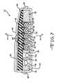
- FIG. 7is a cross-sectional, side view of a cushioning device in accordance with a fifth embodiment of the present invention.
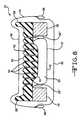
- FIG. 8is a cross-sectional view of the cushioning device of FIG. 7 along line 8 — 8 .
- FIG. 9is a schematic of the cushioning device of FIG. 7 .
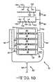
- FIG. 10is a schematic of a sixth embodiment of the present invention.
- FIG. 11is a schematic of a pressure monitoring system.
- FIGS. 1-3A cushioning device 10 in accordance with one embodiment of the present invention is shown in FIGS. 1-3.
- the cushioning device 10includes fluid bladder support sections 12 a-c , which support the user and provide pressure relief to the user so that the development of pressure ulcers is prevented or retarded.
- the cushioning devicealso includes a fluid accumulation reservoir 14 in fluid communication with the fluid bladder support sections 12 a-c .
- the cushioning device 10is a simple device for home or hospital use which eliminates the need for a fluid pump device for making pressure adjustments, thereby making the cushioning device 10 easy to use for an untrained user.
- the cushioning device 10provides a self-adjusting support which delivers the benefits of a powered unit, without the user interface requirement, the energy costs associated with a powered unit, or the power outage or failure concerns of a powered unit.
- the fluid bladder support structureis a bladder having a first section 12 a , a second section 12 b , and a third section 12 c and is capable of being filled with a fluid, although the support structure can have other numbers of sections.
- the first section 12 ais a head support section
- the second section 12 bis a pelvis support section
- the third section 12 cis a lower leg support section, however, any number of fluid support sections 12 can be arranged to support any body portions.
- Each of the first, second, and third sections 12 a-chave a first surface 16 and an opposing second surface 18 .
- a user 46is positioned on cover 48 (described below), although user 46 may be positioned on or adjacent first surface 16 .
- the fluid bladder support sections 12 a-care made of suitable puncture-resistant vinyl film or other suitable air impervious flexible material, such as reinforced films or coated films of vinyl, urethane, or other air impervious materials.
- the bladdersmay be made of one, two, three, or any number of layers of air impervious flexible material.
- each fluid bladder support section 12 a , 12 b , 12 cis comprised of three individual side-by-side cells 20 , however, any number of cells 20 may be used. For example, a single cell for each section 12 a , 12 b , 12 c may be used.
- Each fluid bladder support section 12 a , 12 b , 12 cmay have a height when filled with fluid of about five inches. However, the height of the fluid bladder support section 12 may be varied as desired.
- cells 20may be attached to each other, for example, by heat welding.
- Each of the cells 20is connected through a conduit 22 to a fluid transfer conduit 24 .
- the fluid transfer conduit 24connects, in series, fluid bladder support section 12 a to fluid bladder support section 12 b to fluid bladder support section 12 c and to fluid accumulation reservoir 14 and allows the transfer of fluid from fluid bladder support section 12 a through fluid bladder support sections 12 b and 12 c to fluid accumulation reservoir 14 .
- each of the cells 20 within each sectionmay be interconnected, such that fluid flows between each cell 20 to equalize pressure within each fluid bladder support section 12 a , 12 b , 12 c .
- a single conduit 22would be required to connect each fluid bladder support section 12 a , 12 b , 12 c to the fluid transfer conduit 24 .
- the cells 20 and fluid support sections 12 a-c in this embodimentare substantially rectangular, however, any suitable shape may be used, such as cubic or cylindrical.
- the shape of the cells 20 and fluid support sections 12 a-cis determined by the area of the user being supported and the quantity of cells and fluid bladder support sections used.
- cells 20extend across the width of cushioning device 10 .
- cells 20may extend along the length of cushioning device 10 .
- each cell 20includes an inner resilient device 26 .
- the inner resilient deviceaids in pressure control in the cushioning device 10 .
- the inner resilient device 26is a foam material which allows the flow of fluid therethrough, however, any other suitable resilient device may be used, including, but not limited to, gels, polybeads, elastic materials, and springs.
- the inner resilient device 26is deformable when a load is applied but will return to its original shape (i.e., reform) upon removal of the load.
- the inner resilient device 26is a solid material.
- the inner resilient device 26may include apertures or may be constructed in an I-beam design.
- the resilient devicemay be provided on the outside of the cells 20 .
- the inner resilient deviceis configured to minimize the spring force to the user positioned on the cushioning device 10 . This reduces the tissue interface pressure for the user positioned on the cushioning device 10 .
- the fluid bladder support sections 12 a-cthemselves, may be formed of a resilient material which allows the fluid bladder support sections 12 a-c to deform when a load is applied, but return to their original shape (i.e., reform) upon removal of the load. Any suitable resilient material may be used, as described above.
- Each cell 20may have a plurality of button welds which surround portions of the inner resilient device to prevent ballooning of the cell.
- the button weldsproduce a plurality of interconnected chambers in each cell.
- Such systemsare shown, for example, in U.S. Pat. No. 5,794,289, which is hereby incorporated by reference in its entirety.
- the number of chambers in each cellmay vary, however, suitable numbers of chambers include from about 50 to about 300 chambers. As the chambers exchange air or any other suitable medium, the user's weight is redistributed over the entire cell.
- the cushioning device 10further includes a fluid accumulation reservoir 14 .
- a fluid accumulation reservoir 14Although only one fluid accumulation reservoir 14 is shown, any number of fluid accumulation reservoirs 14 may be used.
- the fluid accumulation reservoir 14is positioned below the feet of the user and is a flexible fluid reservoir, however, the fluid accumulation reservoir(s) may be positioned anywhere within (see, e.g., FIG. 7) or adjacent the cushioning device.
- the fluid accumulation reservoir 14is in fluid communication with the fluid support sections 12 a-c through fluid transfer conduit 24 .
- pressure relief valves 28 a , 28 b , and 28 care positioned in the fluid transfer conduit 24 between fluid bladder support section 12 a and fluid bladder support section 12 b , between fluid bladder support section 12 b and fluid bladder support section 12 c , and between fluid bladder support section 12 c and fluid accumulation reservoir 14 , respectively.
- the pressure relief valves 28 a-care one-way valves which allow fluid to transfer from fluid bladder support section 12 a to fluid bladder support section 12 b when the pressure in fluid bladder support section 12 a exceeds a predetermined relief pressure, from fluid bladder support section 12 b to fluid bladder support section 12 c when the pressure in fluid bladder support section 12 b exceeds a predetermined relief pressure, and from fluid bladder support section 12 c to fluid accumulation reservoir 14 when the pressure in fluid bladder support section 12 c exceeds a predetermined relief pressure.
- Each pressure relief valvemay be set to the same or different predetermined relief pressures, such that each fluid support section is an independently controlled zone. Independently controlled zones allow for greater customization and better meet the unique anatomical needs of the upper body, torso, lower legs, and heel sections.
- Each pressure relief valve 28 a-cmay be limited to a single pressure value or may be adjustable, such that the user determines the pressure of each zone.
- adjustable pressure relief valvesmay include valves which can be adjusted by the user or those which are adjusted by the manufacturer to user specifications. Such adjustable pressure relief valves are known in the art and may include a pressure regulator to permit control of the predetermined relief pressure.
- valves 28 a and 28 bare shown as pressure relief valves, simple one-way or check valves may also be used for valves 28 a and 28 b.
- the cushioning device 10further includes a return conduit 30 .
- Return conduit 30includes a one-way check valve 32 which allows fluid to flow from fluid accumulation reservoir 14 to fluid support section 12 a.
- the cushioning device 10also includes a atmosphere adjustment valve 34 (e.g., a Schrader valve and pin) attached to the fluid accumulation reservoir 14 , although the atmosphere adjustment valve may be positioned at any desired location on the cushioning device 10 .
- the atmosphere adjustment valve 34maintains the cushioning device 10 as an open system during transport to compensate for altitude changes.
- the valveis then closed to close the cushioning device for use.
- the pin of the valveis attached to packaging for the cushioning device 10 such that upon opening the packaging, the valve is closed and the cushioning device is ready for use.
- the systemonce closed, contains fluid which is substantially at atmospheric pressure when no load is applied to the cushioning device 10 .
- the cushioning deviceWhen a load is applied, the cushioning device desirably provides an interface pressure which is lower than that provided by standard hospital mattresses.
- the cushioning device 10may also include a one-way check valve in fluid communication with the atmosphere to replace any lost air, e.g., due to the vapor transmission rate of the materials for the fluid bladder support and accumulation reservoir.
- the cushioning device 10further includes a foam support member 36 on which rest the fluid bladder support sections 12 a-c .
- the foam support member 36may have a thickness of, for example, about one inch.
- the support member 36 in this embodimentis a foam support member, any support material may be used.
- a crib 38Surrounding the periphery of the fluid bladder support sections 12 a-c is a crib 38 . Such cribs are known in the art and are described, for example, in U.S. Pat. No. 5,794,289, which is hereby incorporated by reference in its entirety.
- This crib 38comprises a resilient material, such as foam, foam beads, gels, batting, or other suitable materials, and retains and protects the fluid support sections 12 a-c and conduits 22 , 24 , and 30 .
- the crib 38is a polyurethane foam. Cut outs in the crib 38 may be provided for conduits 22 , 24 , and 30 .
- the crib 38provides strong support for the user or caregiver and facilitates entry and exit stability.
- a wrap 40surrounds the cells 20 in fluid bladder support sections 12 a-c to hold the cells close together and to prevent cell migration and bottoming. However, the cells 20 may be provided without a wrap 40 .
- a top layer 42bridges across and is adhesively or otherwise suitably attached to the upper surface of crib 38 .
- the top layer 42is a foam layer, however, any cushioning material may be used.
- the top layer 42may enhance the comfort of the user and may be a sculpted foam layer.
- the top layer 42may include other features, such as tapering at the foot portion to reduce heel pressures, vent passages from the fluid bladder support area to allow air movement for a low air loss system as described below, and relief holes, channels, grooves, or cavities to allow expansion of the foam in order to minimize the hammock effect created by placing foam over the fluid support bladder area (see, e.g., FIGS. 7 and 8 ).
- the cushioning device 10may include fabric strips or webs composed of non-woven nylon or other suitable strong fabric material which extend between and are attached to the sides of crib 38 to stabilize the crib 38 (see, e.g., U.S. Pat. No. 5,794,289, which is hereby incorporated by reference in its entirety).
- the foam support member 36 , crib 38 , wrap 40 , top layer 42 , and fluid bladder support sections 12 a-care enclosed within a zippered mattress cover 44 .
- the cover 44is made of a suitable material to reduce friction, sheer, and hammocking.
- the cover 44may be made stain resistant and/or moisture resistant. Suitable materials for the cover 44 include, but are not limited to, nylon, especially low vapor transmission nylon, and weft knitted nylon fabric which has an elastomeric polyurethane transfer coating to be water repellent and increase durability, such as that sold by Penn Nyla (Nottingham, England) and identified as Dartex P072, P171, or P272.
- User 46is positioned on a first surface 48 of the cover 44 .
- a second surface 50 of the cover 44may be provided as a non-skid surface, as described in U.S. Pat. No. 5,794,289, which is hereby incorporated by reference in its entirety.
- the cushioning device 10may be provided without any or all of the foam support member 36 , crib 38 , wrap 40 , top layer 42 , and cover 44 (see, e.g., FIG. 7 ), for example, as an overlay for a mattress.
- FIG. 4a second embodiment of the fluid bladder support structure of the present invention is shown. This embodiment of the present invention is identical to the previously described embodiment, except as described below.
- the fluid bladder support structurecomprises two sections 12 d and 12 e .
- Fluid bladder support section 12 dincludes six cells 20 and supports the head and pelvis of the user.
- Fluid bladder support section 12 eincludes three cells 20 and supports the lower legs of the user.
- this embodiment of the present inventionincludes a low air loss system 52 .
- the low air loss system 52includes an air source 53 , such as an electrical air pump (e.g., a powered air loss pump (e.g., model CL250, CL360, or AFP45) marketed by Gaymar Industries, Inc.). However, any suitable air source may be used.
- the air sourceis in fluid communication with a low air loss line 54 , which is in fluid communication with low air loss tubes 56 positioned adjacent the first surface 16 of fluid bladder support section 12 d and extending widthwise. Although shown adjacent all cells 20 , the low air loss tubes may be positioned adjacent any number of cells 20 .
- the low air loss tubesmay be positioned to extend lengthwise (i.e., from a head end to a foot end of the cushioning device) adjacent the fluid bladder support sections (see, e.g., 56 ′ in FIGS. 8 - 10 ).
- the low air loss tubes 56include a plurality of pin holes or micro-vents to produce a gentle flow of air beneath the user and to minimize moisture build-up and/or to regulate temperature of the user.
- a rotational bladder system 58is provided. Suitable rotational bladder systems are known in the art and are described, for example, in U.S. Pat. No. 5,794,289, U.S. Pat. No. 5,926,883, U.S. Pat. No. 6,079,070, and U.S. Pat. No. 6,145,142, which are hereby incorporated by reference in their entirety.
- the rotational bladder system 58includes inlet hoses 60 and 62 which connect to first and second inflatable bladders 64 and 66 , respectively. First and second inflatable bladders 64 and 66 are positioned below fluid support bladder 12 d .
- the first and second inflatable bladders 64 , 66are side-by-side bladders which extend lengthwise, i.e., from a head end to a foot end of the cushioning device 10 , beneath fluid support bladder section 12 d .
- the first and second inflatable bladders 64 , 66each include a connector (not shown) for receiving air from inlet hoses 60 , 62 which are connected to an inflation-deflation device, such as a pump (not shown).
- a single fluid bladder support section 12 dis provided over the bladders 64 , 66 , however, multiple fluid bladder support sections could be used.
- any number of bladders 64 , 66may be used.
- the first and second inflatable bladders 64 , 66are made of suitable puncture-resistant vinyl film or other suitable air impervious flexible material.
- the bladders 64 , 66are suitably formed to be welded together utilizing principles commonly known to those of ordinary skill in the art to which this invention pertains. However, alternative techniques for attaching the first and second inflatable bladders 64 , 66 may be used.
- the first and second inflatable bladders 64 , 66may be formed with notches to provide greater lifting force to the shoulders, chest, and abdomen areas of the user, as described, for example, in U.S. Pat. No. 6,079,070, which is hereby incorporated by reference in its entirety.
- the first inflatable bladder 64For inclining the first surface 16 of the support bladder section 12 d for assisting in turning the user over, the first inflatable bladder 64 is deflated, while the second inflatable bladder 66 is inflated. Likewise, for inclining the first surface 16 of the support bladder section 12 d to the other side for assisting in turning the user over, the second inflatable bladder 66 is deflated, while the first inflatable bladder 64 is inflated.
- the air pressure required to rotate the userdepends on the user's weight, body type, and various other parameters.
- This particular embodimentfurther includes a CPR dump device 68 .
- CPR dump deviceswhich allow for rapid deflation for emergency care (e.g., cardiopulmonary resuscitation (CPR) (see, e.g., U.S. Pat. No. 6,061,855, which is hereby incorporated by reference in its entirety)), are known in the art and will not be described in detail herein.
- the CPR dump device 68includes a short length of high flow tubing (e.g., 1 ⁇ 2 inch tubing) for quick release of air from the turning bladders 64 and 66 and a pin. When the pin is pulled air rapidly exits from the turning bladders 64 and 66 , through conduits 60 and 62 , and out through the short length of high flow tubing.
- a panel 70is also provided for control of the low air loss system 52 and rotational bladder system 58 .
- FIG. 5A third embodiment of the present invention is shown in FIG. 5 .
- This embodiment of the present inventionis identical to the previously described embodiments, except as described below.
- this embodiment of the present inventionincludes an alternating pressure system 72 .
- the fluid bladder support section 12 dis of the alternating pressure type, i.e., it has at least two series of alternating cells, which are alternately inflated and deflated, one series of cells being inflated while the other series of cells is deflated.
- Such alternating pressure type cushionsare disclosed, for example, in U.S. Pat. Nos. 5,794,289 and 5,901,393, which are hereby incorporated by reference in their entirety, and relieve excess pressure on patients at risk of developing pressure ulcers or relieve excess pressure on patients with pressure ulcers.
- the alternating pressure system 72includes an alternating pressure pump 74 , a first conduit 76 connected to a first series of cells 20 ′, and a second conduit 78 connected to a second series of cells 20 ′′.
- disconnect devices 80 for the alternating pressure systemare located on each conduit 76 and 78 .
- the alternating pressure pump 74alternatively inflates and deflates the first series of cells 20 ′ and the second series of cells 20 ′′ in fluid bladder support section 12 d.
- FIG. 6A fourth embodiment of the present invention is shown in FIG. 6 .
- This embodiment of the present inventionis identical to the first embodiment, except as described below.
- the fluid bladder support sections 12 a-care positioned within fluid accumulation reservoir structure 14 ′ having flexible walls 81 which surround and encapsulate the fluid bladder support sections 12 a-c .
- the fluid bladder support sections 12 a-cinclude pressure relief valves 28 a-c , which are in fluid communication with each fluid bladder support section 12 a-c , respectively, and the fluid accumulation reservoir 14 .
- the pressure relief valves 28 a-callow fluid to transfer from fluid bladder support sections 12 a-c to fluid accumulation reservoir 14 when the pressure in the fluid bladder support sections exceeds predetermined relief pressures.
- one-way valves 33 a-care provided in fluid communication with each fluid bladder support section 12 a-c , respectively, and the fluid accumulation reservoir 14 .
- the one-way valves 33 a-callow fluid to transfer from the fluid accumulation reservoir 14 into the fluid bladder support sections 12 a-c , respectively.
- the pressure relief valves 28 a-c and one-way valves 33 a-care in direct communication with the fluid bladder support sections 12 a-c , respectively.
- conduits between fluid bladder support sections 12 a-c and the pressure relief valves 28 a-c and/or the one-way valves 33 a-c , respectively,may be provided.
- valve assemblies 28 a-c and the one-way valves 33 a-ca single valve assembly which allows fluid to transfer from each fluid bladder support section 12 a , 12 b , 12 c to fluid accumulation reservoir 14 when the pressure in the fluid bladder support sections exceeds a predetermined relief pressure and allows one-way fluid transfer from the fluid accumulation reservoir 14 into the fluid bladder support sections 12 a-c may be used.
- cells 20 in fluid bladder support sections 12 a-care interconnected, such that a single pressure relief valve 28 and a single one-way valve 33 is needed for each fluid bladder support section.
- the cells 20may be independent cells, each having a pressure relief valve 28 and a one-way valve 33 .
- the atmosphere adjustment valve 34is closed, making the cushioning device 10 a closed system (i.e., the device is not in fluid communication with the ambient atmosphere or any other external fluid source to control pressure within the fluid bladder support sections during use).
- FIGS. 7-9A fifth embodiment of the present invention is shown in FIGS. 7-9. This embodiment of the present invention is identical to the first embodiment, except as described below.
- fluid accumulation reservoirs 14 a , 14 bare provided in fluid communication with a single fluid support bladder section 12 f .
- Fluid support bladder section 12 fincludes five interconnected cells 20 , each including a resilient device.
- fluid accumulation reservoirs 14 a , 14 bare flexible reservoirs having a fixed maximum volume.
- fluid accumulation reservoirs 14 a , 14 bmay be rigid.
- shut-off valves 84 , 86are located in conduit 82 adjacent fluid accumulation reservoirs 14 a , 14 b , respectively.
- shut-off valves 84 , 86are valves which can be opened or closed manually. Once opened, the valves 84 , 86 stay open until manually closed. Once closed, the valves 84 , 86 stay closed until manually opened. Accordingly, the manually operated shut-off valves 84 , 86 control the passage of fluid between the fluid support bladder section 12 f and each of the reservoirs 14 a , 14 b .
- valve 84When applying a user load to the cushioning device 10 , the manually operated valves are opened, based on the weight of the user. For example, in this embodiment, for a user weighing less than 150 lbs, valve 84 is opened to enable fluid to flow between fluid support bladder section 12 f and fluid accumulation reservoir 14 a . For a user weighing more than 150 lbs, valves 84 and 86 are opened to enable fluid to flow between fluid bladder support section 12 f and fluid accumulation reservoirs 14 a and 14 b . Although two fluid accumulation reservoirs 14 are shown, any number of fluid accumulation reservoirs may be used. The greater the number of fluid accumulation reservoirs, the greater the number of weight ranges of the user that can be controlled. In addition, the cushioning device 10 may be provided without valve 84 .
- the cushioning devicefurther includes a low air loss system 52 ′.
- the low air loss system 52 ′includes a low air loss line 54 ′ which is connected to a supply of fluid (not shown) and two low air loss tubes 56 ′ which extend lengthwise adjacent the fluid bladder support section 12 f .
- the cushioning device 10includes user restraint structures 88 .
- a single restraint structure 88extends along both sides of the cushioning device 10 and is formed into the top layer 42 .
- the restraint structuresmay comprise any number of sections extending along the length of both sides of the cushioning device 10 .
- the restraint structuresmay extend only partially along the sides of the cushioning device 10 .
- the restraint structurescould include only a head-end portion or only a foot end portion. The restraint structures help restrain the user on the cushioning device by providing a structure to reduce the risk that the user will accidentally fall from the cushioning device.
- the restraint structuresmay be interconnected (i.e., in fluid communication) with the fluid support bladder section 12 f through at least one air channel (or other inflation medium transfer channel) and, therefore, are filled with the fluid support bladder section 12 f of the cushioning device 10 .
- the restraint structuresmay be attached to the sides of the cushioning device 10 .
- the restraint structuresextend above a first surface 90 of the top layer 42 .
- the restraint structuresmay extend in any desired dimensions to restrain the user. Suitable restraint structures are described, for example, in U.S. patent application Ser. No. 10/134,341, filed Apr. 26, 2002, which is hereby incorporated by reference in its entirety.
- an additional layer 92is provided adjacent a portion of top layer 42 for additional cushioning.
- Suitable materials for the additional layer 92include, but are not limited to, urethane foam, visco elastic foam, polyethylene foam, polypropylene foam, fiber fill, and polybeads.
- the additional layer 92only partially covers top layer 42 , the additional layer 92 may cover all or any part of top layer 42 .
- the top layer 42includes channels 94 to allow air movement and expansion of the foam, as described above.
- the cushioning device 10includes an inlet 98 for receiving fluid from an inlet hose (not shown).
- the inlet 98may be placed at any position on the cushioning device 10 and is closed during use.
- the systemonce closed, contains fluid which is substantially at atmospheric pressure when no load is applied to the mattress.
- FIG. 10A sixth embodiment of the present invention is shown in FIG. 10 .
- This embodiment of the present inventionis identical to the previously described embodiment, except as described below.
- fluid accumulation reservoirs 14 a and 14 bhave an adjustable volume (i.e., the maximum volume of reservoirs 14 a and 14 b is adjustable).
- fluid accumulation reservoirs 14 a , 14 bare rigid chambers and include a plunger 100 within the reservoirs. Each plunger 100 is movable in the direction of arrows 102 , such that the maximum volume of the reservoirs 14 a and 14 b is determined by the position of the plunger 100 .
- rigid chambers with a plungerare shown, any other suitable variable volume accumulation reservoir may be used, such as a flexible chamber with a clip.
- the adjustment devicee.g., plunger or clip
- the adjustment devicemay be variously positioned to set a volume for each fluid accumulation reservoir based on the weight of the user.
- a scale 104is provided on each fluid accumulation reservoir 14 a , 14 b . Once the volume of each fluid accumulation reservoir is fixed based on the weight of the user, the volume of each fluid accumulation reservoir does not change (i.e., the plunger or clip does not move).
- two adjustable volume fluid accumulation reservoirs 14 a , 14 bare shown, any number of adjustable volume fluid accumulation reservoirs may be used.
- the cushioning device 10may be provided without valves 84 , 86 .
- the cushioning device 10may include a pressure monitoring system, such as that shown in FIG. 11 .
- this embodiment of the pressure monitoring systemincludes a pump 106 , which may be battery operated or plugged into a source of electricity.
- the pump 106is connected to the fluid support bladder 12 through a conduit 108 .
- conduit 108is a pressure sensor 110 and a shut-off valve 112 .
- Sensor 110is used to monitor the pressure within fluid support bladder 12 .
- pump 106is turned on and shut-off valve 112 is opened to allow fluid to enter fluid support bladder 12 until the desired pressure is reached.
- the pump 106 and valve 112may automatically operate to adjust the pressure within support bladder 12 .
- a light systemmay be connected to the sensor 110 to indicate whether the pressure within fluid support bladder 12 is being measured and/or adjusted.
- such devicesactivate a light when the internal pressure of the fluid bladder support section 12 is below a certain level, indicating a bottoming condition.
- the sensor 110may be integrated into the valve 112 through which fluid is being fed into the fluid support bladder 12 or may be positioned within fluid support bladder 12 .
- Other embodiments of such devicesare known in the art and are described, for example, in U.S. Pat. No. 5,140,309, which is hereby incorporated by reference in its entirety.
- the cushioning device 10 of the present inventionmay be provided as part of a cushioning system including a bed having a frame, a plurality of legs, and a support structure, which, for example, may be a conventional box spring.
- the cushioning device 10 of the present inventionmay be positioned adjacent and in contact with the support structure, such that a user may rest on the first surface 16 of the cushioning device 10 which is positioned on the support structure.
- the cushioning systemmay be used, for example, in a hospital or home health care setting.
- the support structure and cushioning device 10may be held together by any suitable device, such as forward and rear straps.
- the forward and rear strapsmay extend under the corners of the support structure or under the support structure from opposite sides and may attach to each other by suitable attachment devices, such as hook and loop fasteners and adhesives.
- a cover 44may be provided over the cushioning device 10 and predetermined portions of the support structure, although it is not required. If a cover is used, the cover is preferably composed of an elastomeric material, which is stretchable and minimizes a “hammocking” effect that interferes with the effectiveness of the inflatable structure.
- a conventional pump, blower, or other inflation devicewhich supplies air or other suitable medium to the cushioning device 10 may be attached onto the frame at the foot end of the bed.
- the cushioning system described aboveis a bed with a box spring
- any suitable type of support structuremay be used.
- other suitable support structuresinclude, but are not limited to, mattresses, chairs, and wheelchairs.
- the cushioning device 10is suitably shaped (e.g., rectangular, square, oval, or circular) and sized to be received by a desired portion of the support structure.
- the cushioning device 10 of the present inventionmay be made to be disposable, thereby eliminating the expense of cleaning and sanitizing the cushioning device 10 after each use, or reusable.
- the cushioning device 10 of the present inventionis positioned on a support structure, such as a bed frame, box spring, chair, or floor. If desired, the cushioning device 10 is secured to the support structure. If present, the atmosphere adjustment valve 34 is closed, such that the fluid bladder support section(s) 12 of the cushioning device contain air which is substantially at atmospheric pressure when no load is applied to the cushioning device. In the alternative, if an inlet 98 is present, the cushioning device is filled with a fluid through the inlet 98 , such that the fluid bladder support section(s) 12 contain fluid at a desired pressure when no load is applied to the cushioning device. Any desired fluid (e.g., air, water) may be used.
- a support structuresuch as a bed frame, box spring, chair, or floor.
- the cushioning device 10is secured to the support structure. If present, the atmosphere adjustment valve 34 is closed, such that the fluid bladder support section(s) 12 of the cushioning device contain air which is substantially at atmospheric pressure when no load is applied to the cushioning device.
- each cell 20 in the fluid bladder support section(s) 12may relieve pressure by adjusting each fluid bladder support section 12 to a predetermined pressure in response to user positioning and movement.
- each fluid support bladder section 12 a-cwill travel through conduit 24 until the desired pressure, as determined by the pressure valves 28 , is reached in each fluid bladder support section 12 a-c .
- Excess fluid from fluid bladder support section 12 cis routed to fluid accumulation reservoir 14 where it is stored.
- the resilient device 26expands creating a partial vacuum within the cells 20 of the fluid bladder support sections 12 a-c .
- This partial vacuumcauses the opening of the one-way valve 32 in return conduit 30 positioned between the fluid accumulation reservoir 14 and fluid bladder support section 12 a . Opening of the valve 32 allows fluid to flow from the fluid accumulation reservoir 14 into fluid bladder support section 12 a , and subsequently to fluid bladder support sections 12 b and 12 c.
- low air loss system 52is activated to produce a flow of air through tubes 56 beneath the user.
- bladders 64 , 66are activated to turn the user from side to side.
- alternating pressure system 72is activated to provide at least two series of alternating cells, which are alternately inflated and deflated, one series of cells being inflated while the other series of cells is deflated.
- each fluid support bladder section 12 a-cwill travel through pressure relief valves 28 a-c , respectively, until the desired pressure, as determined by the pressure relief valves 28 a-c , is reached in each fluid bladder support section 12 a-c .
- Excess fluid from fluid bladder support sections 12 a-cis routed to fluid accumulation reservoir 14 where it is stored.
- the resilient device 26expands creating a partial vacuum within the cells 20 of the fluid bladder support sections 12 a-c . This partial vacuum causes the opening of one or more of the one-way valves 33 . Opening of a valve 33 allows fluid to flow from the fluid accumulation reservoir 14 into the respective fluid bladder support section.
- low air loss system 52is activated to produce a flow of air through tubes 56 beneath the user.
- bladders 64 , 66are activated to turn the user from side to side.
- alternating pressure system 72is activated to provide at least two series of alternating cells, which are alternately inflated and deflated, one series of cells being inflated while the other series of cells is deflated.
- valves 84 and/or 86are opened based on the weight of the user. If only valve 84 is opened, excess fluid from fluid support bladder section 12 f will travel through conduit 82 into fluid accumulation reservoir 14 a , where it is stored. If both valve 84 and valve 86 are opened, excess fluid from fluid support bladder section 12 f will travel through conduit 82 into fluid accumulation reservoirs 14 a and 14 b , as needed, where it is stored.
- the resilient device 26 within the cells 20 of fluid bladder support section 12 fexpands drawing fluid back into fluid bladder support section 12 f from one or both of fluid accumulation reservoirs 14 a and 14 b through conduit 82 . If present, low air loss system 52 ′, rotational bladder system 58 , and/or alternating pressure system 72 is activated.
- plungers 100are positioned in fluid accumulation reservoirs 14 a , 14 b based on the weight of the user.
- valves 84 and/or 86are opened based on the weight of the user. If only valve 84 is opened, excess air from fluid support bladder section 12 f will travel through conduit 82 into fluid accumulation reservoir 14 a , where it is stored. If both valve 84 and valve 86 are opened, excess air from fluid support bladder section 12 f will travel through conduit 82 into fluid accumulation reservoirs 14 a and 14 b , as needed, where it is stored.
- the resilient device 26 within the cells 20 of fluid bladder support section 12 fexpands drawing fluid back into fluid bladder support section 12 f from one or both of fluid accumulation reservoirs 14 a and 14 b through conduit 82 . If present, low air loss system 52 ′, rotational bladder system 58 , and/or alternating pressure system 72 is activated.
Landscapes
- Health & Medical Sciences (AREA)
- Veterinary Medicine (AREA)
- Life Sciences & Earth Sciences (AREA)
- Animal Behavior & Ethology (AREA)
- General Health & Medical Sciences (AREA)
- Public Health (AREA)
- Nursing (AREA)
- Invalid Beds And Related Equipment (AREA)
- Mattresses And Other Support Structures For Chairs And Beds (AREA)
- Transition And Organic Metals Composition Catalysts For Addition Polymerization (AREA)
- Train Traffic Observation, Control, And Security (AREA)
- Diaphragms For Electromechanical Transducers (AREA)
- Buffer Packaging (AREA)
- Fluid-Damping Devices (AREA)
Abstract
Description
Claims (43)
Priority Applications (1)
| Application Number | Priority Date | Filing Date | Title |
|---|---|---|---|
| US10/378,514US6813790B2 (en) | 2002-02-28 | 2003-02-28 | Self-adjusting cushioning device |
Applications Claiming Priority (3)
| Application Number | Priority Date | Filing Date | Title |
|---|---|---|---|
| US36144902P | 2002-02-28 | 2002-02-28 | |
| US42854002P | 2002-11-21 | 2002-11-21 | |
| US10/378,514US6813790B2 (en) | 2002-02-28 | 2003-02-28 | Self-adjusting cushioning device |
Publications (2)
| Publication Number | Publication Date |
|---|---|
| US20030208848A1 US20030208848A1 (en) | 2003-11-13 |
| US6813790B2true US6813790B2 (en) | 2004-11-09 |
Family
ID=27791679
Family Applications (1)
| Application Number | Title | Priority Date | Filing Date |
|---|---|---|---|
| US10/378,514Expired - LifetimeUS6813790B2 (en) | 2002-02-28 | 2003-02-28 | Self-adjusting cushioning device |
Country Status (7)
| Country | Link |
|---|---|
| US (1) | US6813790B2 (en) |
| EP (2) | EP1503645B1 (en) |
| AT (2) | ATE415840T1 (en) |
| DE (2) | DE60336603D1 (en) |
| ES (1) | ES2316741T3 (en) |
| PT (1) | PT1503645E (en) |
| WO (1) | WO2003073825A2 (en) |
Cited By (44)
| Publication number | Priority date | Publication date | Assignee | Title |
|---|---|---|---|---|
| US6953439B1 (en)* | 2002-06-27 | 2005-10-11 | University Of South Florida | Therapeutic mattress |
| US20050283905A1 (en)* | 2002-11-12 | 2005-12-29 | Gray Tek, Inc. | Material mover having a fluid film reservoir |
| US7051389B2 (en) | 2002-05-24 | 2006-05-30 | Tempur World, Llc | Comfort pillow |
| WO2006105169A3 (en)* | 2005-03-28 | 2006-12-14 | Bg Ind Inc | Improved mattress |
| US7263734B1 (en)* | 2006-11-15 | 2007-09-04 | Gaymar Industries, Inc. | Magnetically retained CPR dump |
| US7406736B2 (en)* | 2003-06-27 | 2008-08-05 | Gaymar Industries, Inc. | Stand alone integrated cushion |
| US7444702B2 (en) | 2003-10-14 | 2008-11-04 | Tempur-Pedic Management, Inc. | Pillow top for a cushion |
| US20080271245A1 (en)* | 2007-05-04 | 2008-11-06 | Gaymar Industries, Inc. | Inflatable mattress with uniform restraint |
| US7469437B2 (en) | 2005-06-24 | 2008-12-30 | Tempur-Pedic Management, Inc. | Reticulated material body support and method |
| US20090106898A1 (en)* | 2007-10-31 | 2009-04-30 | Gaymar Industries, Inc. | Adaptable mattress conversion |
| US7530127B2 (en) | 2002-05-24 | 2009-05-12 | Dan-Foam Aps | Pillow and method of manufacturing a pillow |
| US20100071127A1 (en)* | 2008-09-19 | 2010-03-25 | Diacor, Inc. | Systems for patient transfer, devices for movement of a patient, and methods for transfering a patient for treatment |
| US20100146709A1 (en)* | 2008-12-17 | 2010-06-17 | Stryker Corporation | Patient support |
| US7849544B2 (en) | 2007-06-18 | 2010-12-14 | Hill-Rom Industries Sa | Support device of the mattress type comprising a heterogeneous inflatable structure |
| US7849545B2 (en) | 2006-11-14 | 2010-12-14 | Hill-Rom Industries Sa | Control system for hospital bed mattress |
| US20110030144A1 (en)* | 2009-08-06 | 2011-02-10 | Gaymar Industries, Inc. | Cushion bladder with middle layer having gaps and various positioned interior welds |
| US20110061169A1 (en)* | 2009-09-17 | 2011-03-17 | Caremed Supply, Inc. | Air mattress |
| US20110068928A1 (en)* | 2009-09-18 | 2011-03-24 | Riley Carl W | Sensor control for apparatuses for supporting and monitoring a person |
| US20110163885A1 (en)* | 2005-08-10 | 2011-07-07 | Craig Poulos | Adjustable therapeutic mattress |
| US20110301516A1 (en)* | 2010-02-05 | 2011-12-08 | Stryker Corporation | Patient/invalid handling support |
| US8104126B2 (en) | 2007-10-18 | 2012-01-31 | Hill-Rom Industries Sa | Method of inflating, in alternating manner, a support device having inflatable cells, and a device for implementing the method |
| US8108957B2 (en) | 2007-05-31 | 2012-02-07 | Hill-Rom Services, Inc. | Pulmonary mattress |
| US8419660B1 (en) | 2005-06-03 | 2013-04-16 | Primus Medical, Inc. | Patient monitoring system |
| US20130180530A1 (en)* | 2011-07-22 | 2013-07-18 | Prs Medical Technologies, Inc. | Adjustable support system |
| US20130291310A1 (en)* | 2012-05-07 | 2013-11-07 | Caremed Supply Inc. | Sensing device for air cushion bed |
| US20140047645A1 (en)* | 2011-12-05 | 2014-02-20 | Ceragem Cellupedic. Co., Ltd | Mattress and method of adjusting pressure of mattress |
| US8656537B2 (en) | 2006-04-20 | 2014-02-25 | Dan Foam Aps | Multi-component pillow and method of manufacturing and assembling same |
| US20140109319A1 (en)* | 2012-10-19 | 2014-04-24 | Jeffrey W. Wilkinson | Cushioning device and method of cushioning a body |
| US20140173825A1 (en)* | 2011-06-16 | 2014-06-26 | Picard Healthcare Technology (Dongguan) Co. Ltd. | Medical air mattress, method to inflate/deflate a medical air mattress and method to incline the bearing surface of a medical air mattress |
| US20140331408A1 (en)* | 2013-05-08 | 2014-11-13 | Siemens Aktiengesellscaft | Patient support apparatus |
| US8966689B2 (en)* | 2012-11-19 | 2015-03-03 | Select Comfort Corporation | Multi-zone fluid chamber and mattress system |
| US20150320230A1 (en)* | 2014-05-09 | 2015-11-12 | Dreamwell, Ltd. | Firmness control for a smart response technology body support |
| US9326905B2 (en) | 2011-07-22 | 2016-05-03 | Prs Medical Technologies, Inc. | Apparatus and methods for adjusting a support to a body |
| US9333136B2 (en) | 2013-02-28 | 2016-05-10 | Hill-Rom Services, Inc. | Sensors in a mattress cover |
| US9339407B2 (en) | 2011-07-22 | 2016-05-17 | Prs Medical Technologies, Inc. | Apparatus and methods for conforming a support to a body |
| AU2012296734B2 (en)* | 2011-08-16 | 2017-03-16 | Invacare Uk Operations Limited | Pressure relieving mattress |
| US20170128298A1 (en)* | 2012-10-15 | 2017-05-11 | Kap Medical, Inc. | Patient support apparatus and method |
| US9782312B2 (en) | 2013-09-05 | 2017-10-10 | Stryker Corporation | Patient support |
| US9820904B2 (en) | 2011-07-13 | 2017-11-21 | Stryker Corporation | Patient/invalid handling support |
| US10485691B2 (en) | 2011-07-22 | 2019-11-26 | Prs Medical Technologies, Inc. | Independently adjustable support system |
| EP3572058A1 (en) | 2010-08-19 | 2019-11-27 | Stryker Corporation | Multi-walled gelastic mattress system |
| US20210000669A1 (en)* | 2012-06-21 | 2021-01-07 | Hill-Rom Services, Inc. | Mattress bladder control using a bleed valve |
| US11389120B2 (en) | 2019-05-30 | 2022-07-19 | Hill-Rom Services, Inc. | Mattress having selectable patient weight valve, inductive power, and a digital x-ray cassette |
| US12023287B2 (en) | 2012-09-05 | 2024-07-02 | Stryker Corporation | Inflatable mattress and control methods |
Families Citing this family (45)
| Publication number | Priority date | Publication date | Assignee | Title |
|---|---|---|---|---|
| US7434283B2 (en) | 2004-02-13 | 2008-10-14 | M.P.L. Limited | Discrete cell body support and method for using the same to provide dynamic massage |
| US10357114B2 (en) | 1999-04-20 | 2019-07-23 | Wcw, Inc. | Inflatable cushioning device with manifold system |
| US6269505B1 (en) | 1999-04-20 | 2001-08-07 | M.P.L. Ltd. | Inflatable cushioning device with manifold system |
| CH691249A5 (en)* | 2000-05-26 | 2001-06-15 | Marcantonio Del Drago | Mattress or chair seat support has linked chambers with tubes for transmitting fluid from one to another |
| EP1603435B1 (en)* | 2003-03-12 | 2007-08-08 | Jetta Company Limited | Adjustable mattress and pillow system |
| GB2410182A (en)* | 2004-01-20 | 2005-07-27 | Patrick Noel Daly | Pressure reducing patient support structures |
| JP2007535378A (en) | 2004-04-30 | 2007-12-06 | ヒル−ロム サービシーズ,インコーポレイティド | Patient support |
| US20060162779A1 (en)* | 2004-10-08 | 2006-07-27 | Chaffee Robert B | Methods and apparatus for controlling air in inflatable devices |
| US7850629B2 (en)* | 2005-05-02 | 2010-12-14 | Sundaram Ravikumar | Compression apparatus for applying localized pressure to an extremity |
| US8261387B2 (en) | 2006-02-10 | 2012-09-11 | Joerns Llc | Self inflating air mattress |
| ATE534321T1 (en) | 2007-02-16 | 2011-12-15 | Patrick Noel Daly | MATTRESS ARRANGEMENT |
| US8283602B2 (en) | 2007-03-19 | 2012-10-09 | Augustine Temperature Management LLC | Heating blanket |
| US20150366367A1 (en) | 2007-03-19 | 2015-12-24 | Augustine Temperature Management LLC | Electric heating pad with electrosurgical grounding |
| US10201935B2 (en) | 2007-03-19 | 2019-02-12 | Augustine Temperature Management LLC | Electric heating pad |
| US8341786B2 (en)* | 2008-02-14 | 2013-01-01 | Kingsdown, Inc. | Apparatuses and methods providing variable support and variable comfort control of a sleep system and automatic adjustment thereof |
| AU2012216600B2 (en)* | 2008-02-14 | 2014-10-09 | Kingsdown, Inc. | Apparatuses and methods providing variable support and variable comfort control of a sleep system and automatic adjustment thereof |
| WO2009108228A1 (en) | 2008-02-25 | 2009-09-03 | Kingsdown, Inc. | Systems and methods for controlling a bedroom environment and for providing sleep data |
| US10667622B1 (en)* | 2008-07-30 | 2020-06-02 | Youngblood Ip Holdings, Llc | Multi-zone temperature modulation system for bed or blanket |
| WO2012052997A2 (en)* | 2010-10-20 | 2012-04-26 | D.I.P. Plastic Industries Ltd. | Inflatable article and method for its manufacturing |
| WO2013139857A1 (en) | 2012-03-20 | 2013-09-26 | Enmed Ip Ltd. | A cushion assembly |
| US11039962B2 (en) | 2012-04-02 | 2021-06-22 | TurnCare, Inc. | Non-invasive pressure-mitigation apparatuses for improving blood flow and associated systems and methods |
| US20130255699A1 (en) | 2012-04-02 | 2013-10-03 | TurnCare, Inc. | Patient-orienting alternating pressure decubitus prevention support apparatus |
| US9392875B2 (en)* | 2013-01-18 | 2016-07-19 | Fxi, Inc. | Body support system with combination of pressure redistribution and internal air flow guide(s) for withdrawing heat and moisture away from body reclining on support surface of body support system |
| US9138064B2 (en) | 2013-01-18 | 2015-09-22 | Fxi, Inc. | Mattress with combination of pressure redistribution and internal air flow guides |
| DK177590B1 (en)* | 2013-03-30 | 2013-11-04 | Neuro Vision Holding Aps | A bed system |
| US9468301B2 (en)* | 2013-04-30 | 2016-10-18 | Tropitone Furniture Co., Inc. | Seating with adjustable cushions |
| US9962122B2 (en) | 2014-04-10 | 2018-05-08 | Augustine Temperature Management LLC | Underbody warming systems |
| GB201413414D0 (en)* | 2014-07-29 | 2014-09-10 | Direct Healthcare Services Ltd | Mattress |
| WO2016077742A1 (en) | 2014-11-13 | 2016-05-19 | Augustine Temperature Management, Llc | Heated underbody warming systems with electrosurgical grounding |
| US20160255966A1 (en)* | 2015-03-03 | 2016-09-08 | Sealy Technology, Llc | Real time adaptable body support system and method of operation |
| US11628110B2 (en)* | 2015-05-17 | 2023-04-18 | Thinair Surfaces Llc | Support apparatus and method with shear relief |
| GB201509041D0 (en)* | 2015-05-27 | 2015-07-08 | Park House Healthcare Ltd | Reversible cushion means and methods of manufacture and use thereof |
| TWM530637U (en)* | 2016-07-26 | 2016-10-21 | 廣達電腦股份有限公司 | Anti-snore device |
| US10863831B2 (en)* | 2016-08-01 | 2020-12-15 | Polygroup Macau Limited (Bvi) | Systems and methods for air mattress pressure control |
| GB2569281B (en)* | 2017-11-03 | 2022-04-06 | Zommos Holdings Ltd | Mattress interior, mattress and method of manufacturing a mattress |
| US12042453B2 (en)* | 2019-02-26 | 2024-07-23 | Hill-Rom Services, Inc. | Patient positioning apparatus and mattress |
| US10765580B1 (en) | 2019-03-27 | 2020-09-08 | Augustine Biomedical And Design, Llc | Patient securement system for the surgical trendelenburg position |
| JP7402751B2 (en)* | 2020-06-09 | 2023-12-21 | パラマウントベッド株式会社 | Mattresses, sheets, bed systems and air cells |
| US12178949B2 (en) | 2020-10-09 | 2024-12-31 | TurnCare, Inc. | Pressure-mitigation apparatuses for improved treatment of immobilized patients and associated systems and methods |
| US12016812B2 (en) | 2020-10-09 | 2024-06-25 | TurnCare, Inc. | Pressure-mitigation apparatuses for improved treatment of respiratory illnesses and associated systems and methods |
| JP7393101B2 (en)* | 2020-11-30 | 2023-12-06 | トヨタ自動車株式会社 | sleeping equipment |
| US12274367B1 (en)* | 2021-03-31 | 2025-04-15 | Linet Spol. S R.O. | Manual pressure control valve pendant for pneumatic mattress for medical bed |
| CN114712770B (en)* | 2022-04-25 | 2023-05-30 | 重庆三峡学院 | A sports protection pad capable of effectively preventing falling |
| US11844733B1 (en) | 2022-06-23 | 2023-12-19 | Augustine Biomedical And Design, Llc | Patient securement system for the surgical Trendelenburg position |
| WO2025054604A1 (en)* | 2023-09-08 | 2025-03-13 | Bussert Medical, Inc. | Therapeutic cushions having foam inserts and methods of using the same |
Citations (56)
| Publication number | Priority date | Publication date | Assignee | Title |
|---|---|---|---|---|
| US1576211A (en)* | 1925-05-15 | 1926-03-09 | Walter C O'kane | Mattress |
| US3148391A (en) | 1961-11-24 | 1964-09-15 | John K Whitney | Support device |
| US3792501A (en)* | 1973-06-18 | 1974-02-19 | E Kery | Air chairs and convertible sofas |
| US4454615A (en) | 1982-05-03 | 1984-06-19 | Medisearch Pr, Inc. | Air pad with integral securement straps |
| US4483030A (en) | 1982-05-03 | 1984-11-20 | Medisearch Pr, Inc. | Air pad |
| US4679264A (en)* | 1985-05-06 | 1987-07-14 | Mollura Carlos A | Airbed mattress including a regulated, controllable air reservoir therefor |
| US4914771A (en) | 1989-01-23 | 1990-04-10 | Afeyan Industries Inc. | Air mattress |
| US4945588A (en) | 1989-09-06 | 1990-08-07 | Kuss Corporation | Air/water mattress and inflation apparatus |
| US4969459A (en) | 1988-08-29 | 1990-11-13 | Gaymar Industries, Inc. | Infrared heating system for surgical patients |
| US5068935A (en) | 1991-03-21 | 1991-12-03 | Biologics, Inc. | Flotation therapy bed having two part construction |
| US5072468A (en) | 1991-01-22 | 1991-12-17 | Biologics, Inc. | Flotation therapy bed for preventing decubitus ulcers |
| US5109165A (en) | 1990-12-11 | 1992-04-28 | Gaymar Industries, Inc. | Failsafe feedback control system |
| US5140309A (en) | 1991-03-12 | 1992-08-18 | Gaymar Industries, Inc. | Bed signalling apparatus |
| US5184112A (en) | 1991-09-11 | 1993-02-02 | Gaymar Industries, Inc. | Bed patient position monitor |
| US5183039A (en) | 1991-08-23 | 1993-02-02 | Baxter International Inc. | Temperature control device for fluid filled pad |
| USD343531S (en) | 1991-04-25 | 1994-01-25 | Biologics, Inc. | Flotation therapy bed |
| USD351071S (en) | 1991-04-25 | 1994-10-04 | Biologics, Inc. | Flotation therapy bed |
| US5373595A (en) | 1993-03-12 | 1994-12-20 | Irvin Industries Canada Ltd. | Air support device |
| US5398354A (en) | 1993-07-07 | 1995-03-21 | B. G. Industries, Inc. | Heel pillow mattress |
| US5412821A (en) | 1990-10-22 | 1995-05-09 | Span-America Medical Systems, Inc. | Pressure relief support system for a mattress |
| US5423094A (en)* | 1992-12-07 | 1995-06-13 | Michael J. Arsenault | Pneumatic furniture |
| USD368525S (en) | 1992-10-13 | 1996-04-02 | Stuart Karten | Combined bed bracket and tether strap for suspending an air pump on a hospital bed |
| US5611096A (en)* | 1994-05-09 | 1997-03-18 | Kinetic Concepts, Inc. | Positional feedback system for medical mattress systems |
| US5634225A (en) | 1995-05-25 | 1997-06-03 | Foamex L.P. | Modular air bed |
| US5634224A (en) | 1994-08-16 | 1997-06-03 | Gates; Stephen M. | Inflatable cushioning device with self opening intake valve |
| US5649331A (en)* | 1994-06-03 | 1997-07-22 | Span-America Medical Systems, Inc. | Self-adjusting pressure relief support system and methodology |
| US5666681A (en) | 1995-01-03 | 1997-09-16 | Hill-Rom, Inc. | Heel pressure management apparatus and method |
| US5699570A (en)* | 1996-06-14 | 1997-12-23 | Span-America Medical Systems, Inc. | Pressure relief valve vent line mattress system and method |
| US5704084A (en) | 1993-12-06 | 1998-01-06 | Talley Group Limited | Inflatable mattresses |
| US5745939A (en) | 1996-11-12 | 1998-05-05 | Gaymar Industries, Inc. | Leg rest |
| US5787531A (en) | 1994-07-08 | 1998-08-04 | Pepe; Michael Francis | Inflatable pad or mattress |
| US5794289A (en) | 1995-10-06 | 1998-08-18 | Gaymar Industries, Inc. | Mattress for relieving pressure ulcers |
| US5815865A (en) | 1995-11-30 | 1998-10-06 | Sleep Options, Inc. | Mattress structure |
| US5875282A (en) | 1996-10-21 | 1999-02-23 | Gaymar Industries, Inc. | Medical apparatus for warming patient fluids |
| US5901393A (en) | 1996-05-31 | 1999-05-11 | Gaymar Industries Inc. | Alternating pressure support pad |
| US5926884A (en) | 1997-08-05 | 1999-07-27 | Sentech Medical Systems, Inc. | Air distribution device for the prevention and the treatment of decubitus ulcers and pressure sores |
| US5926883A (en) | 1997-08-13 | 1999-07-27 | Gaymar Industries, Inc. | Apparatus and method for controlling a patient positioned upon a cushion |
| US5934280A (en) | 1996-07-23 | 1999-08-10 | Support Systems International Industries | Method and a device having a tap-fed heel support region |
| US5947168A (en) | 1997-03-19 | 1999-09-07 | Support Systems International Industries | Method and apparatus for rapidly deflating and substantially totally emptying an inflatable chamber, in particular a chamber of a support device, such as a mattress |
| US5957872A (en) | 1997-09-04 | 1999-09-28 | Gaymar Industries, Inc. | Heel care device and method |
| US5991949A (en) | 1995-08-15 | 1999-11-30 | Foamex L.P. | Hoseless air bed |
| US6065167A (en) | 1997-09-08 | 2000-05-23 | Gancy; Alan Brian | Fluid-filled flexible-walled chambers having improved resiliency, and methods for controlling their response characteristics |
| US6079070A (en) | 1998-05-28 | 2000-06-27 | Gaymar Industries, Inc. | Disposable inflatable inclinable cushion |
| US6094762A (en) | 1998-02-09 | 2000-08-01 | Hill-Rom Industries, S.A. | Method and apparatus for supporting an element to be supported, in particular the body of a patient, and having an integrated system for achieving pressure equilibrium dynamically and automatically |
| US6099951A (en) | 1998-07-22 | 2000-08-08 | Gaymar Industries, Inc. | Gelatinous composite article and construction |
| US6131469A (en) | 1999-06-18 | 2000-10-17 | Gaymar Industries, Inc. | Shear force measurement device for beds and method |
| US6152169A (en) | 1998-04-20 | 2000-11-28 | Gaymar Industries, Inc. | Pilot operated low pressure shut off valve |
| US6163909A (en) | 1999-07-02 | 2000-12-26 | Lin; Jeng Ming | Pneumatic mattress assembly |
| US6200284B1 (en) | 1999-06-18 | 2001-03-13 | Gaymar Industries, Inc. | Gelastic heel care device and method |
| US6351862B1 (en) | 1997-10-24 | 2002-03-05 | Hill-Rom Services, Inc. | Mattress replacement having air fluidized sections |
| US20020029423A1 (en) | 1997-08-25 | 2002-03-14 | Ellis Craig D. | Mattress assembly |
| US6357491B1 (en) | 1999-07-08 | 2002-03-19 | Gaymar Industries Inc. | Controlling the misuse of an operating-room apparatus |
| US6375633B1 (en) | 2000-05-02 | 2002-04-23 | Gaymar Industries, Inc. | Heel care device and method |
| US6447865B1 (en) | 1998-07-22 | 2002-09-10 | Gaymar Industries, Inc. | Gelatinous composite article and construction |
| US6488043B2 (en) | 2001-04-25 | 2002-12-03 | Gaymar Industries, Inc. | Valve system |
| US6564411B2 (en)* | 2001-03-19 | 2003-05-20 | Shahzad Pirzada | Active fluid channeling system for a bed |
Family Cites Families (9)
| Publication number | Priority date | Publication date | Assignee | Title |
|---|---|---|---|---|
| US368525A (en)* | 1887-08-16 | Half to john w | ||
| DE343531C (en)* | 1916-04-12 | 1921-11-03 | Marconi Wireless Telegraph Co | Device for regulating and maintaining the speed of a machine |
| US4949412A (en)* | 1986-11-05 | 1990-08-21 | Air Plus, Inc. | Closed loop feedback air supply for air support beds |
| JPH02306460A (en)* | 1989-05-19 | 1990-12-19 | Toshiba Corp | cassette loading device |
| JP3118063B2 (en)* | 1992-03-23 | 2000-12-18 | ローム株式会社 | Nonvolatile storage element, nonvolatile storage device using the same, and method of manufacturing nonvolatile storage element |
| US5745942A (en)* | 1995-10-19 | 1998-05-05 | Geomarine Systems, Inc. | Simplified control for lateral rotation therapy mattresses |
| US6203284B1 (en)* | 1995-10-26 | 2001-03-20 | Kabushiki Kaisha Toyoda Jidoshokki Seisakusho | Valve arrangement at the discharge chamber of a variable displacement compressor |
| US5794288A (en) | 1996-06-14 | 1998-08-18 | Hill-Rom, Inc. | Pressure control assembly for an air mattress |
| AU5314799A (en)* | 1998-07-15 | 2000-02-07 | Rostra Precision Controls, Inc. | Electronic control system for a variable support mechanism |
- 2003
- 2003-02-28ATAT03713790Tpatent/ATE415840T1/ennot_activeIP Right Cessation
- 2003-02-28USUS10/378,514patent/US6813790B2/ennot_activeExpired - Lifetime
- 2003-02-28DEDE60336603Tpatent/DE60336603D1/ennot_activeExpired - Lifetime
- 2003-02-28EPEP03713790Apatent/EP1503645B1/ennot_activeExpired - Lifetime
- 2003-02-28PTPT03713790Tpatent/PT1503645E/enunknown
- 2003-02-28EPEP08016929Apatent/EP2000057B1/ennot_activeExpired - Lifetime
- 2003-02-28ATAT08016929Tpatent/ATE503404T1/ennot_activeIP Right Cessation
- 2003-02-28DEDE60325043Tpatent/DE60325043D1/ennot_activeExpired - Lifetime
- 2003-02-28WOPCT/US2003/006184patent/WO2003073825A2/ennot_activeApplication Discontinuation
- 2003-02-28ESES03713790Tpatent/ES2316741T3/ennot_activeExpired - Lifetime
Patent Citations (62)
| Publication number | Priority date | Publication date | Assignee | Title |
|---|---|---|---|---|
| US1576211A (en)* | 1925-05-15 | 1926-03-09 | Walter C O'kane | Mattress |
| US3148391A (en) | 1961-11-24 | 1964-09-15 | John K Whitney | Support device |
| US3792501A (en)* | 1973-06-18 | 1974-02-19 | E Kery | Air chairs and convertible sofas |
| US4454615A (en) | 1982-05-03 | 1984-06-19 | Medisearch Pr, Inc. | Air pad with integral securement straps |
| US4483030A (en) | 1982-05-03 | 1984-11-20 | Medisearch Pr, Inc. | Air pad |
| US4679264A (en)* | 1985-05-06 | 1987-07-14 | Mollura Carlos A | Airbed mattress including a regulated, controllable air reservoir therefor |
| US4969459A (en) | 1988-08-29 | 1990-11-13 | Gaymar Industries, Inc. | Infrared heating system for surgical patients |
| US4914771A (en) | 1989-01-23 | 1990-04-10 | Afeyan Industries Inc. | Air mattress |
| US4945588A (en) | 1989-09-06 | 1990-08-07 | Kuss Corporation | Air/water mattress and inflation apparatus |
| US5412821A (en) | 1990-10-22 | 1995-05-09 | Span-America Medical Systems, Inc. | Pressure relief support system for a mattress |
| US5109165A (en) | 1990-12-11 | 1992-04-28 | Gaymar Industries, Inc. | Failsafe feedback control system |
| US5072468A (en) | 1991-01-22 | 1991-12-17 | Biologics, Inc. | Flotation therapy bed for preventing decubitus ulcers |
| US5140309A (en) | 1991-03-12 | 1992-08-18 | Gaymar Industries, Inc. | Bed signalling apparatus |
| US5068935A (en) | 1991-03-21 | 1991-12-03 | Biologics, Inc. | Flotation therapy bed having two part construction |
| USD343531S (en) | 1991-04-25 | 1994-01-25 | Biologics, Inc. | Flotation therapy bed |
| USD351071S (en) | 1991-04-25 | 1994-10-04 | Biologics, Inc. | Flotation therapy bed |
| US5183039A (en) | 1991-08-23 | 1993-02-02 | Baxter International Inc. | Temperature control device for fluid filled pad |
| EP0558713A1 (en) | 1991-08-23 | 1993-09-08 | Gaymar Industries Inc. | Temperature control device and method of calibration |
| JPH06503438A (en) | 1991-08-23 | 1994-04-14 | ゲイマー インダストリーズ インコーポレイテッド | Temperature control device and conversion method |
| US5184112A (en) | 1991-09-11 | 1993-02-02 | Gaymar Industries, Inc. | Bed patient position monitor |
| USD368525S (en) | 1992-10-13 | 1996-04-02 | Stuart Karten | Combined bed bracket and tether strap for suspending an air pump on a hospital bed |
| US5423094A (en)* | 1992-12-07 | 1995-06-13 | Michael J. Arsenault | Pneumatic furniture |
| US5373595A (en) | 1993-03-12 | 1994-12-20 | Irvin Industries Canada Ltd. | Air support device |
| US5398354A (en) | 1993-07-07 | 1995-03-21 | B. G. Industries, Inc. | Heel pillow mattress |
| US5704084A (en) | 1993-12-06 | 1998-01-06 | Talley Group Limited | Inflatable mattresses |
| US5611096A (en)* | 1994-05-09 | 1997-03-18 | Kinetic Concepts, Inc. | Positional feedback system for medical mattress systems |
| US5649331A (en)* | 1994-06-03 | 1997-07-22 | Span-America Medical Systems, Inc. | Self-adjusting pressure relief support system and methodology |
| US5652985A (en)* | 1994-06-03 | 1997-08-05 | Span-America Medical Systems, Inc. | Self-adjusting pressure relief support system and methodology |
| US5787531A (en) | 1994-07-08 | 1998-08-04 | Pepe; Michael Francis | Inflatable pad or mattress |
| US5634224A (en) | 1994-08-16 | 1997-06-03 | Gates; Stephen M. | Inflatable cushioning device with self opening intake valve |
| US5666681A (en) | 1995-01-03 | 1997-09-16 | Hill-Rom, Inc. | Heel pressure management apparatus and method |
| US5634225A (en) | 1995-05-25 | 1997-06-03 | Foamex L.P. | Modular air bed |
| US5991949A (en) | 1995-08-15 | 1999-11-30 | Foamex L.P. | Hoseless air bed |
| US5794289A (en) | 1995-10-06 | 1998-08-18 | Gaymar Industries, Inc. | Mattress for relieving pressure ulcers |
| US5815865A (en) | 1995-11-30 | 1998-10-06 | Sleep Options, Inc. | Mattress structure |
| US5901393A (en) | 1996-05-31 | 1999-05-11 | Gaymar Industries Inc. | Alternating pressure support pad |
| US5699570A (en)* | 1996-06-14 | 1997-12-23 | Span-America Medical Systems, Inc. | Pressure relief valve vent line mattress system and method |
| US5934280A (en) | 1996-07-23 | 1999-08-10 | Support Systems International Industries | Method and a device having a tap-fed heel support region |
| US5875282A (en) | 1996-10-21 | 1999-02-23 | Gaymar Industries, Inc. | Medical apparatus for warming patient fluids |
| US5745939A (en) | 1996-11-12 | 1998-05-05 | Gaymar Industries, Inc. | Leg rest |
| US6061855A (en) | 1996-11-12 | 2000-05-16 | Gaymar Industries, Inc. | CPR dump manifold |
| US5947168A (en) | 1997-03-19 | 1999-09-07 | Support Systems International Industries | Method and apparatus for rapidly deflating and substantially totally emptying an inflatable chamber, in particular a chamber of a support device, such as a mattress |
| US5926884A (en) | 1997-08-05 | 1999-07-27 | Sentech Medical Systems, Inc. | Air distribution device for the prevention and the treatment of decubitus ulcers and pressure sores |
| US5926883A (en) | 1997-08-13 | 1999-07-27 | Gaymar Industries, Inc. | Apparatus and method for controlling a patient positioned upon a cushion |
| US6145142A (en) | 1997-08-13 | 2000-11-14 | Gaymar Industries, Inc. | Apparatus and method for controlling a patient positioned upon a cushion |
| US20020029423A1 (en) | 1997-08-25 | 2002-03-14 | Ellis Craig D. | Mattress assembly |
| US5957872A (en) | 1997-09-04 | 1999-09-28 | Gaymar Industries, Inc. | Heel care device and method |
| GB2346809A (en) | 1997-09-04 | 2000-08-23 | Gaymar Ind Inc | Heel care device and method |
| US6065167A (en) | 1997-09-08 | 2000-05-23 | Gancy; Alan Brian | Fluid-filled flexible-walled chambers having improved resiliency, and methods for controlling their response characteristics |
| US6351862B1 (en) | 1997-10-24 | 2002-03-05 | Hill-Rom Services, Inc. | Mattress replacement having air fluidized sections |
| US6094762A (en) | 1998-02-09 | 2000-08-01 | Hill-Rom Industries, S.A. | Method and apparatus for supporting an element to be supported, in particular the body of a patient, and having an integrated system for achieving pressure equilibrium dynamically and automatically |
| US6152169A (en) | 1998-04-20 | 2000-11-28 | Gaymar Industries, Inc. | Pilot operated low pressure shut off valve |
| US6079070A (en) | 1998-05-28 | 2000-06-27 | Gaymar Industries, Inc. | Disposable inflatable inclinable cushion |
| US6099951A (en) | 1998-07-22 | 2000-08-08 | Gaymar Industries, Inc. | Gelatinous composite article and construction |
| US6447865B1 (en) | 1998-07-22 | 2002-09-10 | Gaymar Industries, Inc. | Gelatinous composite article and construction |
| US6200284B1 (en) | 1999-06-18 | 2001-03-13 | Gaymar Industries, Inc. | Gelastic heel care device and method |
| US6131469A (en) | 1999-06-18 | 2000-10-17 | Gaymar Industries, Inc. | Shear force measurement device for beds and method |
| US6163909A (en) | 1999-07-02 | 2000-12-26 | Lin; Jeng Ming | Pneumatic mattress assembly |
| US6357491B1 (en) | 1999-07-08 | 2002-03-19 | Gaymar Industries Inc. | Controlling the misuse of an operating-room apparatus |
| US6375633B1 (en) | 2000-05-02 | 2002-04-23 | Gaymar Industries, Inc. | Heel care device and method |
| US6564411B2 (en)* | 2001-03-19 | 2003-05-20 | Shahzad Pirzada | Active fluid channeling system for a bed |
| US6488043B2 (en) | 2001-04-25 | 2002-12-03 | Gaymar Industries, Inc. | Valve system |
Cited By (93)
| Publication number | Priority date | Publication date | Assignee | Title |
|---|---|---|---|---|
| US7530127B2 (en) | 2002-05-24 | 2009-05-12 | Dan-Foam Aps | Pillow and method of manufacturing a pillow |
| US7051389B2 (en) | 2002-05-24 | 2006-05-30 | Tempur World, Llc | Comfort pillow |
| US7735169B2 (en) | 2002-05-24 | 2010-06-15 | Tempur-Pedic Management, Inc. | Comfort pillow |
| US7415742B2 (en) | 2002-05-24 | 2008-08-26 | Tempur World, Llc | Comfort pillow |
| US6953439B1 (en)* | 2002-06-27 | 2005-10-11 | University Of South Florida | Therapeutic mattress |
| US20050283905A1 (en)* | 2002-11-12 | 2005-12-29 | Gray Tek, Inc. | Material mover having a fluid film reservoir |
| US7725963B2 (en) | 2002-11-12 | 2010-06-01 | Gray Tek, Inc. | Material mover having a fluid film reservoir |
| US7406736B2 (en)* | 2003-06-27 | 2008-08-05 | Gaymar Industries, Inc. | Stand alone integrated cushion |
| US7444702B2 (en) | 2003-10-14 | 2008-11-04 | Tempur-Pedic Management, Inc. | Pillow top for a cushion |
| US7707670B2 (en) | 2003-10-14 | 2010-05-04 | Tempur-Pedic Management, Inc. | Pillow top for a cushion |
| US20100180384A1 (en)* | 2005-03-28 | 2010-07-22 | B.G. Industries, Inc. | Mattress |
| US7886386B2 (en) | 2005-03-28 | 2011-02-15 | Bg Industries, Llc. | Mattress |
| WO2006105169A3 (en)* | 2005-03-28 | 2006-12-14 | Bg Ind Inc | Improved mattress |
| CN101296640B (en)* | 2005-03-28 | 2010-07-28 | B.G.工业公司 | Improved mattress |
| US8419660B1 (en) | 2005-06-03 | 2013-04-16 | Primus Medical, Inc. | Patient monitoring system |
| US7469437B2 (en) | 2005-06-24 | 2008-12-30 | Tempur-Pedic Management, Inc. | Reticulated material body support and method |
| US8418297B2 (en) | 2005-06-24 | 2013-04-16 | Tempur-Pedic Management, Llc | Reticulated material body support and method |
| US20110163885A1 (en)* | 2005-08-10 | 2011-07-07 | Craig Poulos | Adjustable therapeutic mattress |
| US8656537B2 (en) | 2006-04-20 | 2014-02-25 | Dan Foam Aps | Multi-component pillow and method of manufacturing and assembling same |
| US7849545B2 (en) | 2006-11-14 | 2010-12-14 | Hill-Rom Industries Sa | Control system for hospital bed mattress |
| US7263734B1 (en)* | 2006-11-15 | 2007-09-04 | Gaymar Industries, Inc. | Magnetically retained CPR dump |
| US20080271245A1 (en)* | 2007-05-04 | 2008-11-06 | Gaymar Industries, Inc. | Inflatable mattress with uniform restraint |
| US7954186B2 (en) | 2007-05-04 | 2011-06-07 | Gaymar Industries, Inc. | Inflatable mattress with uniform restraint |
| US8108957B2 (en) | 2007-05-31 | 2012-02-07 | Hill-Rom Services, Inc. | Pulmonary mattress |
| US8584279B2 (en) | 2007-05-31 | 2013-11-19 | Hill-Rom Services, Inc. | Pulmonary mattress |
| US7849544B2 (en) | 2007-06-18 | 2010-12-14 | Hill-Rom Industries Sa | Support device of the mattress type comprising a heterogeneous inflatable structure |
| US8104126B2 (en) | 2007-10-18 | 2012-01-31 | Hill-Rom Industries Sa | Method of inflating, in alternating manner, a support device having inflatable cells, and a device for implementing the method |
| US8347436B2 (en) | 2007-10-31 | 2013-01-08 | Stryker Corporation | Adaptable mattress conversion |
| US20090106898A1 (en)* | 2007-10-31 | 2009-04-30 | Gaymar Industries, Inc. | Adaptable mattress conversion |
| US8640279B2 (en) | 2008-09-19 | 2014-02-04 | Diacor, Inc. | Systems for patient transfer, devices for movement of a patient, and methods for transferring a patient |
| US9693921B2 (en) | 2008-09-19 | 2017-07-04 | Diacor, Inc. | Systems for patient transfer, devices for movement of a patient, and methods for transferring a patient |
| US8490226B2 (en)* | 2008-09-19 | 2013-07-23 | Diacor, Inc. | Systems for patient transfer, devices for movement of a patient, and methods for transferring a patient for treatment |
| US20100071127A1 (en)* | 2008-09-19 | 2010-03-25 | Diacor, Inc. | Systems for patient transfer, devices for movement of a patient, and methods for transfering a patient for treatment |
| US20100146709A1 (en)* | 2008-12-17 | 2010-06-17 | Stryker Corporation | Patient support |
| US8910334B2 (en) | 2008-12-17 | 2014-12-16 | Stryker Corporation | Patient support |
| US20100175196A1 (en)* | 2008-12-17 | 2010-07-15 | Patrick Lafleche | Patient support |
| US8332979B2 (en) | 2009-08-06 | 2012-12-18 | Stryker Corporation | Cushion bladder with middle layer having gaps and various positioned interior welds |
| US20110030144A1 (en)* | 2009-08-06 | 2011-02-10 | Gaymar Industries, Inc. | Cushion bladder with middle layer having gaps and various positioned interior welds |
| US8635726B2 (en) | 2009-08-06 | 2014-01-28 | Stryker Corporation | Cushion bladder with middle layer having gaps and various positioned interior welds |
| US20110061169A1 (en)* | 2009-09-17 | 2011-03-17 | Caremed Supply, Inc. | Air mattress |
| US8156589B2 (en)* | 2009-09-17 | 2012-04-17 | Caremed Supply, Inc. | Air mattress |
| US9775758B2 (en) | 2009-09-18 | 2017-10-03 | Hill-Rom Services, Inc. | Person support apparatus having physiological sensor |
| US10111794B2 (en) | 2009-09-18 | 2018-10-30 | Hill-Rom Services, Inc. | Person support apparatus having physiological sensor |
| US8525679B2 (en)* | 2009-09-18 | 2013-09-03 | Hill-Rom Services, Inc. | Sensor control for apparatuses for supporting and monitoring a person |
| US9013315B2 (en) | 2009-09-18 | 2015-04-21 | Hill-Rom Services, Inc. | Sensor control for apparatuses for supporting and monitoring a person |
| US20110068928A1 (en)* | 2009-09-18 | 2011-03-24 | Riley Carl W | Sensor control for apparatuses for supporting and monitoring a person |
| US9549675B2 (en) | 2009-09-18 | 2017-01-24 | Hill-Rom Services, Inc. | Sensor control for apparatuses for supporting and monitoring a person |
| US10583058B2 (en) | 2009-09-18 | 2020-03-10 | Hill-Rom Services, Inc. | Person support apparatus having physiological sensor |
| US8911387B2 (en)* | 2010-02-05 | 2014-12-16 | Stryker Corporation | Patient/invalid handling support |
| US8832885B2 (en) | 2010-02-05 | 2014-09-16 | Stryker Corporation | Patient/invalid handling support |
| US8856992B2 (en) | 2010-02-05 | 2014-10-14 | Stryker Corporation | Patient/invalid handling support |
| US8397326B2 (en) | 2010-02-05 | 2013-03-19 | Stryker Corporation | Patient/invalid handling support |
| US20110301516A1 (en)* | 2010-02-05 | 2011-12-08 | Stryker Corporation | Patient/invalid handling support |
| EP3572058A1 (en) | 2010-08-19 | 2019-11-27 | Stryker Corporation | Multi-walled gelastic mattress system |
| US20140173825A1 (en)* | 2011-06-16 | 2014-06-26 | Picard Healthcare Technology (Dongguan) Co. Ltd. | Medical air mattress, method to inflate/deflate a medical air mattress and method to incline the bearing surface of a medical air mattress |
| US9566202B2 (en)* | 2011-06-16 | 2017-02-14 | Picard Healthcare Technology (Dongguan Co. Ltd.) | Medical air mattress, method to inflate/deflate a medical air mattress and method to incline the bearing surface of a medical air mattress |
| US10987265B2 (en) | 2011-07-13 | 2021-04-27 | Stryker Corporation | Patient/invalid handling support |
| US9820904B2 (en) | 2011-07-13 | 2017-11-21 | Stryker Corporation | Patient/invalid handling support |
| US12213926B2 (en) | 2011-07-13 | 2025-02-04 | Stryker Corporation | Patient/invalid handling support |
| US12329700B2 (en) | 2011-07-13 | 2025-06-17 | Stryker Corporation | Patient/invalid handling support with immersion sensing |
| US10485691B2 (en) | 2011-07-22 | 2019-11-26 | Prs Medical Technologies, Inc. | Independently adjustable support system |
| US9339407B2 (en) | 2011-07-22 | 2016-05-17 | Prs Medical Technologies, Inc. | Apparatus and methods for conforming a support to a body |
| US20130180530A1 (en)* | 2011-07-22 | 2013-07-18 | Prs Medical Technologies, Inc. | Adjustable support system |
| US11446171B2 (en) | 2011-07-22 | 2022-09-20 | Prs Medical Technologies, Inc. | Independently adjustable support system |
| US9326905B2 (en) | 2011-07-22 | 2016-05-03 | Prs Medical Technologies, Inc. | Apparatus and methods for adjusting a support to a body |
| US9849052B2 (en)* | 2011-08-16 | 2017-12-26 | Invacare Uk Operations Limited | Pressure relieving mattress |
| AU2012296734B2 (en)* | 2011-08-16 | 2017-03-16 | Invacare Uk Operations Limited | Pressure relieving mattress |
| US20140047645A1 (en)* | 2011-12-05 | 2014-02-20 | Ceragem Cellupedic. Co., Ltd | Mattress and method of adjusting pressure of mattress |
| US9271578B2 (en)* | 2011-12-05 | 2016-03-01 | Ceragem Cellupedic. Co., Ltd | Mattress and method of adjusting pressure of mattress |
| US20130291310A1 (en)* | 2012-05-07 | 2013-11-07 | Caremed Supply Inc. | Sensing device for air cushion bed |
| US8745796B2 (en)* | 2012-05-07 | 2014-06-10 | Caremed Supply Inc. | Sensing device for air cushion bed |
| US12102577B2 (en)* | 2012-06-21 | 2024-10-01 | Hill-Rom Services, Inc. | Mattress bladder control using a bleed valve |
| US20210000669A1 (en)* | 2012-06-21 | 2021-01-07 | Hill-Rom Services, Inc. | Mattress bladder control using a bleed valve |
| US12023287B2 (en) | 2012-09-05 | 2024-07-02 | Stryker Corporation | Inflatable mattress and control methods |
| US11679048B2 (en) | 2012-10-15 | 2023-06-20 | Kap Medical, Inc. | Patient support apparatus and method |
| US20170128298A1 (en)* | 2012-10-15 | 2017-05-11 | Kap Medical, Inc. | Patient support apparatus and method |
| US11020299B2 (en)* | 2012-10-15 | 2021-06-01 | Kap Medical, Inc. | Patient support apparatus and method |
| CN105025754B (en)* | 2012-10-19 | 2017-07-14 | 杰弗里·W·威尔金森 | Cushioning device and method for cushioning a human body |
| WO2014063132A1 (en)* | 2012-10-19 | 2014-04-24 | Wilkinson Jeffrey W | Cushioning device and method of cushioning a body |
| CN105025754A (en)* | 2012-10-19 | 2015-11-04 | 杰弗里·W·威尔金森 | Cushion device and method for cushioning human body |
| US20140109319A1 (en)* | 2012-10-19 | 2014-04-24 | Jeffrey W. Wilkinson | Cushioning device and method of cushioning a body |
| US8943627B2 (en)* | 2012-10-19 | 2015-02-03 | Jeffrey W. Wilkinson | Cushioning device and method of cushioning a body |
| AU2013331024B2 (en)* | 2012-10-19 | 2017-12-14 | Jeffrey W. Wilkinson | Cushioning device and method of cushioning a body |
| US9826842B2 (en)* | 2012-10-19 | 2017-11-28 | Jeffrey W. Wilkinson | Cushioning device and method of cushioning a body |
| US8966689B2 (en)* | 2012-11-19 | 2015-03-03 | Select Comfort Corporation | Multi-zone fluid chamber and mattress system |
| US11684529B2 (en) | 2013-02-28 | 2023-06-27 | Hill-Rom Services, Inc. | Mattress cover sensor method |
| US9333136B2 (en) | 2013-02-28 | 2016-05-10 | Hill-Rom Services, Inc. | Sensors in a mattress cover |
| US20140331408A1 (en)* | 2013-05-08 | 2014-11-13 | Siemens Aktiengesellscaft | Patient support apparatus |
| US9782312B2 (en) | 2013-09-05 | 2017-10-10 | Stryker Corporation | Patient support |
| US20150320230A1 (en)* | 2014-05-09 | 2015-11-12 | Dreamwell, Ltd. | Firmness control for a smart response technology body support |
| US10548410B2 (en)* | 2014-05-09 | 2020-02-04 | Dreamwell, Ltd. | Firmness control for a smart response technology body support |
| US11826185B2 (en) | 2019-05-30 | 2023-11-28 | Hill-Rom Services, Inc. | Mattress having selectable patient weight valve, inductive power, and a digital x-ray cassette |
| US11389120B2 (en) | 2019-05-30 | 2022-07-19 | Hill-Rom Services, Inc. | Mattress having selectable patient weight valve, inductive power, and a digital x-ray cassette |
Also Published As
| Publication number | Publication date |
|---|---|
| WO2003073825A3 (en) | 2004-12-16 |
| ATE415840T1 (en) | 2008-12-15 |
| EP1503645A4 (en) | 2006-11-22 |
| PT1503645E (en) | 2009-02-18 |
| US20030208848A1 (en) | 2003-11-13 |
| EP2000057A1 (en) | 2008-12-10 |
| DE60336603D1 (en) | 2011-05-12 |
| WO2003073825A2 (en) | 2003-09-12 |
| DE60325043D1 (en) | 2009-01-15 |
| EP2000057B1 (en) | 2011-03-30 |
| ATE503404T1 (en) | 2011-04-15 |
| EP1503645A2 (en) | 2005-02-09 |
| ES2316741T3 (en) | 2009-04-16 |
| EP1503645B1 (en) | 2008-12-03 |
Similar Documents
| Publication | Publication Date | Title |
|---|---|---|
| US6813790B2 (en) | Self-adjusting cushioning device | |
| US9750655B2 (en) | Conformable support system | |
| US6739001B2 (en) | Cushioning device including a restraint structure | |
| US7380302B2 (en) | Bolster system and method | |
| US6065166A (en) | Surgical support cushion apparatus and method | |
| US7155766B1 (en) | Bolster system and method | |
| US5647079A (en) | Inflatable patient support surface system | |
| US7191482B2 (en) | Patient support | |
| US5794289A (en) | Mattress for relieving pressure ulcers | |
| US7617555B2 (en) | Patient support surface | |
| US5634225A (en) | Modular air bed | |
| US6079070A (en) | Disposable inflatable inclinable cushion | |
| AU779556B2 (en) | Inflatable cushioning device with manifold system | |
| US5701622A (en) | Pulsating operating table cushion | |
| US10555848B2 (en) | Portable cushion and method of use | |
| US20080178392A1 (en) | Air Cushion with Alternatively Inflated Chambers | |
| US20190307259A1 (en) | Hybrid air immersion mattress | |
| WO1997012531A1 (en) | Pressure ulcer-relieving mattress |
Legal Events
| Date | Code | Title | Description |
|---|---|---|---|
| AS | Assignment | Owner name:GAYMAR INDUSTRIES, INC., NEW YORK Free format text:ASSIGNMENT OF ASSIGNORS INTEREST;ASSIGNORS:FLICK, ROLAND E.;PAOLINI, RAYMOND P.;JUSIAK, JOEL T.;REEL/FRAME:014089/0570 Effective date:20030415 | |
| STCF | Information on status: patent grant | Free format text:PATENTED CASE | |
| FPAY | Fee payment | Year of fee payment:4 | |
| AS | Assignment | Owner name:GENERAL ELECTRIC CAPITAL CORPORATION, AS COLLATERA Free format text:SECURITY AGREEMENT;ASSIGNOR:GAYMAR INDUSTRIES, INC.;REEL/FRAME:022473/0556 Effective date:20090330 | |
| AS | Assignment | Owner name:GAYMAR INDUSTRIES, INC., NEW YORK Free format text:RELEASE BY SECURED PARTY;ASSIGNOR:GENERAL ELECTRIC CAPITAL CORPORATION;REEL/FRAME:025114/0294 Effective date:20101001 | |
| AS | Assignment | Owner name:STRYKER CORPORATION, MICHIGAN Free format text:ASSIGNMENT OF ASSIGNORS INTEREST;ASSIGNOR:GAYMAR INDUSTRIES, INC.;REEL/FRAME:027025/0001 Effective date:20110819 | |
| FEPP | Fee payment procedure | Free format text:PAT HOLDER NO LONGER CLAIMS SMALL ENTITY STATUS, ENTITY STATUS SET TO UNDISCOUNTED (ORIGINAL EVENT CODE: STOL); ENTITY STATUS OF PATENT OWNER: LARGE ENTITY | |
| FEPP | Fee payment procedure | Free format text:PAYOR NUMBER ASSIGNED (ORIGINAL EVENT CODE: ASPN); ENTITY STATUS OF PATENT OWNER: LARGE ENTITY | |
| FPAY | Fee payment | Year of fee payment:8 | |
| FPAY | Fee payment | Year of fee payment:12 |