US6813343B1 - Method and apparatus for filtering asymmetric digital subscriber line (ADSL) signals - Google Patents
Method and apparatus for filtering asymmetric digital subscriber line (ADSL) signalsDownload PDFInfo
- Publication number
- US6813343B1 US6813343B1US09/310,518US31051899AUS6813343B1US 6813343 B1US6813343 B1US 6813343B1US 31051899 AUS31051899 AUS 31051899AUS 6813343 B1US6813343 B1US 6813343B1
- Authority
- US
- United States
- Prior art keywords
- coupled
- telephone
- attenuator
- lowpass filter
- hook
- Prior art date
- Legal status (The legal status is an assumption and is not a legal conclusion. Google has not performed a legal analysis and makes no representation as to the accuracy of the status listed.)
- Expired - Lifetime
Links
Images


Classifications
- H—ELECTRICITY
- H04—ELECTRIC COMMUNICATION TECHNIQUE
- H04M—TELEPHONIC COMMUNICATION
- H04M11/00—Telephonic communication systems specially adapted for combination with other electrical systems
- H04M11/06—Simultaneous speech and data transmission, e.g. telegraphic transmission over the same conductors
- H04M11/062—Simultaneous speech and data transmission, e.g. telegraphic transmission over the same conductors using different frequency bands for speech and other data
- H—ELECTRICITY
- H04—ELECTRIC COMMUNICATION TECHNIQUE
- H04L—TRANSMISSION OF DIGITAL INFORMATION, e.g. TELEGRAPHIC COMMUNICATION
- H04L27/00—Modulated-carrier systems
- H04L27/26—Systems using multi-frequency codes
- H04L27/2601—Multicarrier modulation systems
Definitions
- the present inventionrelates generally to data and voice communications over digital subscriber lines and, more particularly, to a method and apparatus for filtering signals in a splitterless asymmetric digital subscriber line (ADSL) system.
- ADSLdigital subscriber line
- Asymmetric Digital Subscriber Linerefers to a new modem technology that allows existing twisted pair telephone lines to be converted into a high-performance access path for multimedia and high-speed data communications.
- An ADSL circuitconnects an ADSL modem on each end of the twisted pair telephone line, creating three information channels—a high speed downstream (central office to end user) channel, a medium speed upstream (end user to central office) channel, and a POTS (“Plain Old Telephone Service”) channel.
- the POTS channelis separated from the ADSL modem by filters, thus guaranteeing uninterrupted POTS, even if the ADSL circuit fails.
- telephone equipment and signalsneed not be limited to voice communications, but may also include other technologies, for example equipment and signals compatible with regular telephone lines, such as facsimiles machines, voiceband modems (for example, V.90 modems), answering machines, and the like.
- Full-rate ADSLuses POTS splitters to separate the POTS channel from the ADSL data signals.
- a POTS splitteris installed at each end of the line and includes a lowpass filter for separating out POTS telephone voice communication signals and a highpass filter for separating out data communication signals.
- the POTS splitterdivides the subscriber line into two separate twisted pairs—one for data communication (ADSL) and one for telephone voice communication signals (POTS).
- ADSLdata communication
- POTStelephone voice communication signals
- the ADSL modemincludes a high-pass filter that rejects the POTS telephone voice communication signal, while every telephone instrument in the house is connected to the telephone line through a low-pass filter that rejects the ADSL data signals.
- FIG. 1is a block diagram illustrating a splitterless ADSL system of the prior art.
- Customer premises equipment (CPE) 101is coupled to central office (CO) 102 by digital subscriber line (DSL) 103 .
- CPE 101includes a highpass filter 104 , ADSL modem 107 , computer 108 , lowpass filters 105 and 106 , and telephone instruments 109 and 110 .
- Computer 108is coupled to ADSL modem 107 , which is coupled to highpass filter 104 , which is coupled to DSL 103 .
- Telephone instrument 109is coupled to lowpass filter 105 , which is coupled to DSL 103 .
- Telephone instrument 110is coupled to lowpass filter 106 , which is coupled to DSL 103 .
- CO 102includes a POTS (“plain old telephone service”) splitter 111 , ADSL modem 112 , data switch 113 , voice switch 114 , data network 115 , and voice network 116 .
- DSL 103is coupled to POTS splitter 111 , which is coupled to voice switch 114 and ADSL modem 112 .
- Voice switch 114is coupled to voice network 116 .
- ADSL modem 112is coupled to data switch 113 , which is coupled to data network 115 .
- Voice communications passing through voice switch 114are passed through POTS splitter 111 and applied to DSL 103 as baseband signals.
- Data communications passing through data switch 113are modulated at a frequency range higher than that of the baseband POTS signals and passed through POTS splitter 111 and applied to DSL 103 . Since the data communications are transmitted at a different frequency range than the voice communications, frequency-division-multiplexing (FDM) allows simultaneous transmission of both voice communications (POTS) and data communications over a single DSL 103 .
- FDMfrequency-division-multiplexing
- highpass filter 104 and lowpass filters 105 and 106provide selective filtering of the voice and data communications.
- Highpass filter 104passes the higher frequency data communications to ADSL modem 107 and computer 108 , while blocking the lower frequency baseband voice communications.
- Lowpass filters 105 and 106pass the lower frequency baseband voice communications to telephone instruments 109 and 110 , respectively, while blocking the higher frequency data communications.
- lowpass filters 105 and 106exhibit a deficiency that can adversely affect the performance of the ADSL system.
- the frequency response of lowpass filters 105 and 106changes based on the status of telephone instruments 109 and 110 , respectively. For example, while lowpass filter 105 might properly differentiate between voice communications and data communications when telephone instrument 109 is off-hook (e.g, when telephone instrument 109 is in use), the electrical characteristics of lowpass filter 105 are altered when telephone instrument 109 is returned to its on-hook state (e.g., when the user hangs up). This change in the electrical characteristics of lowpass filter 105 can cause interference with the data communications between ADSL modem 107 of CPE 101 and ADSL modem 112 of CO 102 . Thus, a circuit is needed that will allow telephone instruments, such as telephone instruments 109 and 110 , to change between their off-hook and on-hook states without adversely affecting ongoing data communications over DSL 103 .
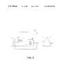
- FIG. 2is a block diagram illustrating a lowpass filter and telephone instrument of the prior art.
- Lowpass filter 201is coupled to telephone instrument 202 .
- Telephone instrument 202includes a load 203 , which exhibits a load impedance.
- Load 203is coupled in series with hookswitch 204 .
- hookswitch 204When telephone instrument 202 is off-hook, hookswitch 204 is closed, coupling load 203 to lowpass filter 201 .
- hookswitch 204is open, disconnecting load 203 from lowpass filter 201 .
- the electrical characteristicse.g., the frequency response
- the electrical characteristics of lowpass filter 201are affected by load 203 . Therefore, a circuit is needed to compensate for the undesirable interaction between load 203 and lowpass filter 201 .
- the present inventionis directed to a method and apparatus for filtering ADSL signals.
- the filtering technique provided by the inventionavoids interference when telephone instruments coupled to a DSL switch between the off-hook and on-hook states.
- One embodiment of the inventionprovides a variable inductance in series with a simple lowpass filter used to block high-frequency data communications signals. The variable inductance is controlled by an off-hook detector that senses the status of the telephone instrument hookswitch.
- Another embodiment of the inventionincludes a parallel combination of a resistance element and a switch in series with the DSL to provide attenuation and control the overall electrical characteristics of the filter assembly and telephone instrument.
- Another embodiment of the inventionincludes an inductive element with a saturable core in series with the DSL. The saturable character of the inductor core results in the inductive element having different electrical properties depending on whether the telephone instrument is on-hook or off-hook.
- the inventionreduces interference to data communications that can otherwise occur in a splitterless ADSL system if a telephone instrument changes hookswitch state.
- FIG. 1is a block diagram illustrating a splitterless ADSL system of the prior art.
- FIG. 2is a block diagram illustrating a lowpass filter and telephone instrument of the prior art.
- FIG. 3is a block diagram illustrating one embodiment of the present invention.
- FIG. 4is a block diagram illustrating one embodiment of the present invention.
- FIG. 5is a block diagram illustrating one embodiment of the present invention.
- FIG. 6is a flow diagram illustrating one embodiment of the present invention.
- FIG. 7is a schematic diagram illustrating one embodiment of the invention.
- FIG. 8is a schematic diagram illustrating one embodiment of the invention.
- FIG. 9is a schematic diagram illustrating one embodiment of the invention.
- FIG. 10is a schematic diagram illustrating one embodiment of the invention.
- the present inventionrelates to a method and apparatus for filtering ADSL signals.
- the filtering technique of the inventionavoids interference caused by a telephone instrument changing between on-hook and off-hook states.
- a telephone filter for splitterless ADSL in accordance with the present inventionincludes a lowpass filter, an off-hook detector, an additional attenuator, and one or more switches.
- the telephone filter in accordance with the present inventionchanges its input impedance and frequency characteristics as a function of DC current in the telephone line.
- the lowpass filteris a passive LC circuit that provides the necessary attenuation for ADSL data communications signals, for example, about 50-60 dB for the typically lowest ADSL frequency of 30 kHz.
- the off-hook detectoris an active circuit that senses DC current flow in the telephone line.
- the DC current in a telephone lineis very low, for example, about 10 microamperes.
- the lowpass filteris connected to the telephone line through an additional attenuator that has a high and determined input impedance over a wide frequency range from 30 Hz to 10 MHz.
- the off-hook detector of one embodiment of the inventionsenses this current, activates appropriate switches and connects the lowpass filter to the telephone line. The additional attenuator is disconnected in this situation.
- the telephone filteroperates like a lowpass filter that passes a telephone voice communications signal and stops a higher-frequency data communications signal.
- a telephone filter configured according to the present inventiontypically has a high input impedance for telephone voice communications and data communications signals. As a result, a telephone filter loaded by the higher input impedance of an on-hook telephone will not cause distortion to another off-hook telephone.
- the additional attenuatoris a resistor that connects in series with the lowpass filter. This: attenuator is shorted by an electronic or mechanical switch.
- the additional attenuatoris a saturated inductance, that is connected in series with the lowpass filter. This attenuator changes its impedance through the action of DC current flowing through the circuit.
- FIG. 3is a block diagram illustrating one embodiment of the present invention.
- Lowpass filter assembly 301is coupled to telephone instrument 302 .
- Lowpass filter assemblyincludes variable attenuator 305 , off-hook detector 306 , and lowpass filter 307 .
- Telephone instrument 302includes load 303 and hookswitch 304 .
- Load 303is coupled in series with hookswitch 304 , which is coupled to off-hook detector 306 of lowpass filter assembly 301 .
- Off-hook detector 306is coupled to lowpass filter 307 , which is coupled to variable attenuator 305 , which is coupled to DSL 308 .
- Off-hook detector 306senses whether hookswitch 304 is in an off-hook or on-hook state. Off-hook detector 306 may detect changes of DSL current to determine the state of hookswitch 304 . Off-hook detector 306 senses the current through DSL 308 . For example, a low-value resistor may be placed in series with DSL 308 and the voltage across the resistor measured by off-hook detector 306 . As another alternative, an optocoupler circuit may be used to sense the current through DSL 308 . The level of attenuation provided by variable attenuator 305 may be controlled based on this measurement of current through DSL 308 . As yet another alternative, off-hook detector 306 may employ mechanical means or sensors to determine the state of the hookswitch 304 .
- Off-hook detector 306need not be located between lowpass filter 307 and hookswitch 304 . Rather, off-hook detector 306 may be configured in any manner that provides adequate sensing of the status of hookswitch 304 . For example, off-hook detector 306 may be located between lowpass filter 307 and variable attenuator 305 or somewhere along DSL 308 beyond variable attenuator 305 .
- FIG. 4is a block diagram illustrating one embodiment of the present invention.
- Lowpass filter assembly 401is coupled to telephone instrument 402 .
- Lowpass filter assembly 401includes off-hook detector 403 , lowpass filter 404 , resistance element 405 , and switch 406 .
- Off-hook detector 403is coupled to telephone instrument 402 and lowpass filter 404 .
- Lowpass filter 404is coupled to the parallel combination of resistance element 405 and switch 406 .
- Resistance element 405 and switch 406are coupled to DSL 407 .
- Off-hook detector 403controls the operation of switch 406 .
- off-hook detector 403detects an off-hook state, it causes switch 406 to close.
- switch 406is closed, it shorts resistance element 405 , reducing the effective attenuation of DSL 407 .
- off-hook detector 403detects an on-hook state, it causes switch 406 to open.
- switch 406is open, it has the effect of electrically inserting resistance element 405 in series with DSL 407 .
- Resistance element 405serves to attenuate signals present on DSL 407 . The increased attenuation provided by resistance element 405 compensates for the effect on lowpass filter 404 from being disconnected from the telephone instrument load by the action of the telephone instrument hookswitch.
- Off-hook detector 403need not be located between lowpass filter 404 and telephone
- off-hook detector 403may be configured in any manner that allows it to detect the status of the telephone instrument hookswitch.
- off-hook detector 403may be located between lowpass filter 404 and the parallel combination of resistance element 405 and switch 406 or on DSL 407 somewhere beyond the parallel combination of resistance element 405 and switch 406 .
- FIG. 5is a block diagram illustrating one embodiment of the present invention.
- Lowpass filter assembly 501is coupled to telephone instrument 502 .
- Lowpass filter assembly 501includes lowpass filter 503 and inductive element 504 with saturable core 505 .
- Inductive element 504 with saturable core 505is configured in series with DSL 506 and lowpass filter 503 .
- inductive element 504When telephone instrument 502 is in an on-hook state, negligible current flows through inductive element 504 . Thus, saturable core 505 is not saturated, and inductor 504 introduces significant impedance in the circuit, thereby attenuating signals present on DSL 506 and compensating for the influence of the state of telephone instrument 502 on the electrical characteristics of lowpass filter 503 .
- inductor 504When telephone instrument 502 is in an off-hook state, significant DC current flows through inductor 504 , saturating saturable core 505 . When saturable core 505 is saturated, the amount of attenuation it provides is reduced. This reduction in attenuation is offset by the influence of the hookswitch of telephone instrument 502 on the electrical characteristics of lowpass filter 503 . By compensating for the changing status of the telephone instrument impedance, inductive element 504 with saturable core 505 avoids interference to data communications occurring on DSL 506 .
- FIG. 6is a flow diagram illustrating a process according to one embodiment of the present invention.
- the processbegins at step 601 .
- a decisionis made as to whether or not the telephone instrument is in an off-hook state. If not, the process remains at step 602 . However, if the telephone instrument is in an off-hook state, the process proceeds to step 603 .
- the attenuation associated with a lowpass filteris reduced.
- step 604a determination is made as to whether or not the telephone instrument is still in the off-hook state. If it is, the process remains at step 604 . If not, the process continues to step 605 .
- step 605the attenuation associated with the lowpass filter is increased and the process returns to step 602 .
- FIG. 7is a schematic diagram illustrating one embodiment of the invention.
- Lowpass filter assembly 701is coupled to telephone instrument 702 .
- Lowpass filter assemblyincludes off-hook detector 703 , low pass filter 704 , two resistance elements 705 and two switches 706 .
- Off-hook detector 703is coupled to the telephone device 702 and lowpass filter 704 .
- Lowpass filter 704is coupled to the two parallel combinations of resistance element 705 and switch 706 .
- Two resistive elements 705 and two switches 706are coupled to DSL 707 .
- Protection device 711is connected to the input of lowpass filter assembly 701 for lighting protection.
- the switches 706are implemented by optoMOS relay 708 .
- This relay 708has low on resistance, for example about 15 ohms and very high off impedance, for example about several megohms.
- Input light emitting diode (LED) 709 of optorelay 708is very sensitive. Its turn-on input current is as small as 0.5 milliamperes, for example.
- Off-hook detector 703is a simple Schottky diode bridge 710 that is connected in series, for example, into one wire of the twisted pair DSL 707 .
- the impedance of the lowpass filter assembly 701is high, for example, about 3 kiloohms, because of the resistive elements 705 .
- resistive elements 705contribute to the high impedance of the lowpass filter assembly 701 because optorelays 708 have very low capacitance, for example about 10 picofarads, between their inputs and outputs.
- lowpass filter 704contributes to the high impedance of the lowpass filter assembly 701 because lowpass filter 704 includes input inductance 710 connected in series with DSL 707 .
- One advantage of this embodiment of this inventionis the high breakdown voltage of optorelays 708 , for example about 400 VDC between output pins and more than 3 KV between input and output. This makes it possible to use this lowpass filter assembly 701 for a home telephone network or other telephone or communication network in accordance with existing standards.
- FIG. 8is a schematic diagram illustrating one embodiment of the invention.
- Inline filter 801comprises attenuator 802 , lowpass filter 803 , off-hook detector 806 , and switches 808 .
- Attenuator 802is coupled to telephone line 809 , which preferably comprises two conductors, and to lowpass filter 803 .
- Switches 808are also coupled to telephone line 809 and to lowpass filter 803 .
- Lowpass filter 803comprises inductors 804 and capacitor 805 , with one of inductors 804 configured in series with each conductor of telephone line 809 as it extends through inline filter 801 .
- Capacitor 805is configured in parallel with the conductors.
- other types of lowpass filtersmay be used to provide lowpass filter 803 .
- Off-hook detector 806is coupled to lowpass filter 803 and to line 810 , which comprises two conductors and is coupled to telephone equipment, such as a telephone instrument or other station equipment.
- Line 810preferably comprises two conductors.
- Off-hook detector 806provides control outputs 807 to switches 808 .
- Attenuator 802comprises attenuation elements coupled to each conductor of telephone line 809 .
- these attenuation elementsmay be resistors or other impedance elements, preferably impedance elements exhibiting a relatively high resistance component as compared with their reactance components.
- off-hook detector 806detects the off-hook state and provides the appropriate control signals on control outputs 807 to switches 808 , causing switches 808 to close. With switches 808 closed, switches 808 short out the attenuation elements of attenuator 802 . Thus, by closing switches 808 , attenuator 802 is effectively removed from the circuit between telephone line 809 and lowpass filter 803 .
- the circuit of FIG. 8automatically controls attenuator 802 and switches 808 to provide compensation for the performance of lowpass filter 803 when the impedance of telephone equipment coupled to line 810 changes in transition between on-hook and off-hook states.
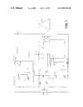
- FIG. 9is a schematic diagram illustrating one embodiment of the invention.
- Inline filter 901comprises attenuator 902 , lowpass filter 903 , and off-hook detector 906 .
- Attenuator 902is coupled to telephone line 909 , which preferably comprises two conductors, and to lowpass filter 903 .
- Attenuator 902comprises a saturable inductance element or other impedance element exhibiting substantial inductive reactance in series with each conductor of telephone line 909 .
- Lowpass filter 903comprises inductors 904 and capacitor 905 , with one inductor configured in series with each conductor of telephone line 909 as it extends through inline filter 901 .
- Capacitor 905is configured in parallel with the conductors.
- Off-hook detector 906is coupled to lowpass filter 903 and to telephone equipment, such as a telephone instrument or other station equipment coupled to line 910 .
- Line 910preferably comprises two conductors.
- Off-hook detector 906provides control outputs 907 to attenuator 902 .
- off-hook detector 906provides signals to attenuator 902 to prevent current from flowing through secondary windings of the saturable inductive elements, such as saturable core inductors or saturable core transformers. Without this current flowing, the saturable inductive elements of attenuator 902 effectively insert a substantial impedance in series with lowpass filter 903 . This inductance works in conjunction with the elements of lowpass filter 903 to change the characteristics of lowpass filter 903 to compensate for the higher on-hook impedance of the telephone equipment coupled to line 910 .
- off-hook detector 906provides signals to attenuator 902 to cause current to flow through the secondary windings of the saturable inductive elements.
- the saturable inductive elementsbecome saturated with magnetic flux, thereby effectively reducing the inductance of the primary windings of the saturable inductive elements.
- lowpass filter 903provides the appropriate frequency response in conjunction with the impedance of the telephone equipment coupled to line 910 .
- circuit of FIG. 9provides automatic adjustment of the characteristics of lowpass filter 903 to compensate for changes in impedance of telephone equipment coupled to line 910 when the telephone equipment switches between the on-hook and off-hook states.
- FIG. 10is a schematic diagram illustrating one embodiment of the invention.
- Inline filter 1001comprises attenuator 1002 , lowpass filter 1003 , diode bridge 1011 , and optocouplers 1012 .
- Attenuator 1002is coupled to telephone line 1009 and to lowpass filter 1003 .
- Diode bridge 1011is coupled to lowpass filter 1003 and to telephone equipment, such as a telephone instrument or other station equipment, connected to line 1010 .
- Line 1010preferably comprises two conductors.
- Diode bridge 1011comprises four diodes, preferably Schottky diodes or other diodes having low forward voltage ratings. The diodes are configured such that two diodes, one of each polarity orientation, are coupled to lowpass filter 1003 and two diodes, one of each polarity orientation, are coupled to one conductor of line 1010 .
- the remaining terminals of these four diodesare coupled anode-to-anode and cathode-to-cathode to form two nodes at which control outputs are provided to the LED or input portions of optocouplers 1012 .
- Additional componentsfor example current limiting resistors may be provided in series with the LED or input portions of optocouplers 1012 .
- diode bridge 1011causes current to flow through the LED or input portions of optocouplers 1012 .
- the LED or input portions of optocouplers 1012provide an optical signal to the photodiode portions of optocouplers 1012 .
- the photodiode portions of optocouplers 1012are coupled to MOSFET switches of optocouplers 1012 .
- the MOSFET switchesclose when optical signals are received at the photodiodes portions of optocouplers 1012 .
- Examples of optocouplers 1012 with which the invention may be practicedinclude optoMOS relays and other optoelectronic devices.
- Attenuator 1002comprises attenuation elements, for example resistors or other impedance elements.
- Attenuator 1002comprises attenuation elements, for example resistors or other impedance elements.
- Lowpass filter 1003preferably comprises inductors 1004 and capacitor 1005 , with one inductor 1004 configured in series with each conductor of telephone line 1009 as it extends through inline filter 1001 and with capacitor 1005 configured in parallel across the conductors.
- the characteristics of lowpass filter 1003are adjusted to compensate for the difference in impedance of the telephone equipment between the on-hook state and the off-hook state.
- While this inventionis useful in an ADSL context, it may also be practiced with other types of communications lines, especially communication lines where additional signals are frequency division multiplexed at higher frequencies over low-frequency signals.
- additional signalssuch as data signals
- the inventionmay be applied to prevent interference to telephone equipment from the new signals.
- AMLadded main line
- the present inventionmay be applied to prevent interference between the AML system and the existing telephone equipment.
- the inventionmay be applied to any type of network or wiring where filtering is to occur in the presence of dynamic electrical characteristics.
Landscapes
- Engineering & Computer Science (AREA)
- Computer Networks & Wireless Communication (AREA)
- Signal Processing (AREA)
- Telephonic Communication Services (AREA)
- Filters And Equalizers (AREA)
Abstract
Description
Claims (6)
Priority Applications (2)
| Application Number | Priority Date | Filing Date | Title |
|---|---|---|---|
| US09/310,518US6813343B1 (en) | 1999-05-12 | 1999-05-12 | Method and apparatus for filtering asymmetric digital subscriber line (ADSL) signals |
| EP00110073AEP1079589A2 (en) | 1999-05-12 | 2000-05-12 | Method and apparatus for filtering asymmetric digital subcriber line (ADSL) signals |
Applications Claiming Priority (1)
| Application Number | Priority Date | Filing Date | Title |
|---|---|---|---|
| US09/310,518US6813343B1 (en) | 1999-05-12 | 1999-05-12 | Method and apparatus for filtering asymmetric digital subscriber line (ADSL) signals |
Publications (1)
| Publication Number | Publication Date |
|---|---|
| US6813343B1true US6813343B1 (en) | 2004-11-02 |
Family
ID=23202864
Family Applications (1)
| Application Number | Title | Priority Date | Filing Date |
|---|---|---|---|
| US09/310,518Expired - LifetimeUS6813343B1 (en) | 1999-05-12 | 1999-05-12 | Method and apparatus for filtering asymmetric digital subscriber line (ADSL) signals |
Country Status (2)
| Country | Link |
|---|---|
| US (1) | US6813343B1 (en) |
| EP (1) | EP1079589A2 (en) |
Cited By (23)
| Publication number | Priority date | Publication date | Assignee | Title |
|---|---|---|---|---|
| US20010019608A1 (en)* | 2000-01-27 | 2001-09-06 | Bengt Gustav Lofmark | Method and arrangement for filtering of signals |
| US20030154331A1 (en)* | 2002-02-13 | 2003-08-14 | Globespanvirata Incorporated | System and method for shared use of common GPIO line |
| US20040228361A1 (en)* | 1999-12-21 | 2004-11-18 | Intel Corporation | Modular broadband adapter system |
| US20050226393A1 (en)* | 2004-04-08 | 2005-10-13 | Smith Donald S | Voice over DSL adapter for test equipment |
| US6996134B1 (en)* | 2001-05-07 | 2006-02-07 | General Bandwidth Inc. | System and method for reliably communicating telecommunication information |
| US20070127454A1 (en)* | 2001-04-24 | 2007-06-07 | General Bandwidth Inc. | System and Method for Providing Lifeline Telecommunication Service |
| US7593394B2 (en) | 2000-04-18 | 2009-09-22 | Mosaid Technologies Incorporated | Telephone communication system over a single telephone line |
| US7633966B2 (en) | 2000-04-19 | 2009-12-15 | Mosaid Technologies Incorporated | Network combining wired and non-wired segments |
| US7680255B2 (en) | 2001-07-05 | 2010-03-16 | Mosaid Technologies Incorporated | Telephone outlet with packet telephony adaptor, and a network using same |
| US7686653B2 (en) | 2003-09-07 | 2010-03-30 | Mosaid Technologies Incorporated | Modular outlet |
| US7702095B2 (en) | 2003-01-30 | 2010-04-20 | Mosaid Technologies Incorporated | Method and system for providing DC power on local telephone lines |
| US7715534B2 (en) | 2000-03-20 | 2010-05-11 | Mosaid Technologies Incorporated | Telephone outlet for implementing a local area network over telephone lines and a local area network using such outlets |
| US7746905B2 (en) | 2003-03-13 | 2010-06-29 | Mosaid Technologies Incorporated | Private telephone network connected to more than one public network |
| US7965735B2 (en) | 1998-07-28 | 2011-06-21 | Mosaid Technologies Incorporated | Local area network of serial intelligent cells |
| US7990908B2 (en) | 2002-11-13 | 2011-08-02 | Mosaid Technologies Incorporated | Addressable outlet, and a network using the same |
| US8351582B2 (en) | 1999-07-20 | 2013-01-08 | Mosaid Technologies Incorporated | Network for telephony and data communication |
| US20130251114A1 (en)* | 2010-11-23 | 2013-09-26 | British Telecommunications Plc | System for providing telephony and data services |
| US8582598B2 (en) | 1999-07-07 | 2013-11-12 | Mosaid Technologies Incorporated | Local area network for distributing data communication, sensing and control signals |
| US8611528B2 (en) | 2004-02-16 | 2013-12-17 | Mosaid Technologies Incorporated | Outlet add-on module |
| US9025744B2 (en) | 2010-09-10 | 2015-05-05 | British Telecommunications Public Limited Company | System for providing telephony and data services |
| US20160330334A1 (en)* | 2013-12-31 | 2016-11-10 | British Telecommunications Public Limited Company | Method and apparatus for use in supplying power over a telephone line |
| CN108768571A (en)* | 2018-07-17 | 2018-11-06 | 北京科络捷通讯产品有限责任公司 | The frequency division multiplexing transmission method and device of G.fast signals, VDSL2 signals and voice signal in copper wire |
| US10986164B2 (en) | 2004-01-13 | 2021-04-20 | May Patents Ltd. | Information device |
Families Citing this family (3)
| Publication number | Priority date | Publication date | Assignee | Title |
|---|---|---|---|---|
| CN1575559A (en)* | 2001-10-24 | 2005-02-02 | 卡提纳网络公司 | Method and apparatus for transient suppression in an integrated pots/dsl line card |
| DE10203221A1 (en)* | 2002-01-28 | 2003-08-21 | Siemens Ag | Device and method for avoiding retrain processes with integrated voice and xDSL data transmission #### |
| DE10240140A1 (en)* | 2002-08-30 | 2004-03-25 | Siemens Ag | Communication arrangement and transmission unit for transmitting information via at least one transmission line and a circuit arrangement connectable to the transmission unit |
Citations (5)
| Publication number | Priority date | Publication date | Assignee | Title |
|---|---|---|---|---|
| US2924667A (en)* | 1957-08-13 | 1960-02-09 | Bell Telephone Labor Inc | Reduction of transmission loss in bridged subscriber loops |
| US3881068A (en)* | 1974-05-16 | 1975-04-29 | Bell Telephone Labor Inc | Bridge lifter for telephone line |
| US5832077A (en)* | 1994-05-04 | 1998-11-03 | Lucent Technologies Inc. | Microphone/loudspeaker having a speakerphone mode and a microphone/loudspeaker mode |
| US6115466A (en)* | 1998-03-12 | 2000-09-05 | Westell Technologies, Inc. | Subscriber line system having a dual-mode filter for voice communications over a telephone line |
| US6181777B1 (en) | 1998-11-19 | 2001-01-30 | Excelsus Technologies, Inc. | Impedance blocking filter circuit |
- 1999
- 1999-05-12USUS09/310,518patent/US6813343B1/ennot_activeExpired - Lifetime
- 2000
- 2000-05-12EPEP00110073Apatent/EP1079589A2/ennot_activeWithdrawn
Patent Citations (5)
| Publication number | Priority date | Publication date | Assignee | Title |
|---|---|---|---|---|
| US2924667A (en)* | 1957-08-13 | 1960-02-09 | Bell Telephone Labor Inc | Reduction of transmission loss in bridged subscriber loops |
| US3881068A (en)* | 1974-05-16 | 1975-04-29 | Bell Telephone Labor Inc | Bridge lifter for telephone line |
| US5832077A (en)* | 1994-05-04 | 1998-11-03 | Lucent Technologies Inc. | Microphone/loudspeaker having a speakerphone mode and a microphone/loudspeaker mode |
| US6115466A (en)* | 1998-03-12 | 2000-09-05 | Westell Technologies, Inc. | Subscriber line system having a dual-mode filter for voice communications over a telephone line |
| US6181777B1 (en) | 1998-11-19 | 2001-01-30 | Excelsus Technologies, Inc. | Impedance blocking filter circuit |
Cited By (54)
| Publication number | Priority date | Publication date | Assignee | Title |
|---|---|---|---|---|
| US8885660B2 (en) | 1998-07-28 | 2014-11-11 | Conversant Intellectual Property Management Incorporated | Local area network of serial intelligent cells |
| US8325636B2 (en) | 1998-07-28 | 2012-12-04 | Mosaid Technologies Incorporated | Local area network of serial intelligent cells |
| US8867523B2 (en) | 1998-07-28 | 2014-10-21 | Conversant Intellectual Property Management Incorporated | Local area network of serial intelligent cells |
| US7986708B2 (en) | 1998-07-28 | 2011-07-26 | Mosaid Technologies Incorporated | Local area network of serial intelligent cells |
| US7965735B2 (en) | 1998-07-28 | 2011-06-21 | Mosaid Technologies Incorporated | Local area network of serial intelligent cells |
| US8885659B2 (en) | 1998-07-28 | 2014-11-11 | Conversant Intellectual Property Management Incorporated | Local area network of serial intelligent cells |
| US8908673B2 (en) | 1998-07-28 | 2014-12-09 | Conversant Intellectual Property Management Incorporated | Local area network of serial intelligent cells |
| US8582598B2 (en) | 1999-07-07 | 2013-11-12 | Mosaid Technologies Incorporated | Local area network for distributing data communication, sensing and control signals |
| US8351582B2 (en) | 1999-07-20 | 2013-01-08 | Mosaid Technologies Incorporated | Network for telephony and data communication |
| US8929523B2 (en) | 1999-07-20 | 2015-01-06 | Conversant Intellectual Property Management Inc. | Network for telephony and data communication |
| US20040228361A1 (en)* | 1999-12-21 | 2004-11-18 | Intel Corporation | Modular broadband adapter system |
| US7200156B2 (en)* | 1999-12-21 | 2007-04-03 | Skarpness Mark L | Modular broadband adapter system |
| US7447305B2 (en)* | 2000-01-27 | 2008-11-04 | Telefonaktiebolaget Lm Ericsson (Publ) | Method and arrangement for filtering of signals |
| US20010019608A1 (en)* | 2000-01-27 | 2001-09-06 | Bengt Gustav Lofmark | Method and arrangement for filtering of signals |
| US7715534B2 (en) | 2000-03-20 | 2010-05-11 | Mosaid Technologies Incorporated | Telephone outlet for implementing a local area network over telephone lines and a local area network using such outlets |
| US8855277B2 (en) | 2000-03-20 | 2014-10-07 | Conversant Intellectual Property Managment Incorporated | Telephone outlet for implementing a local area network over telephone lines and a local area network using such outlets |
| US8363797B2 (en) | 2000-03-20 | 2013-01-29 | Mosaid Technologies Incorporated | Telephone outlet for implementing a local area network over telephone lines and a local area network using such outlets |
| US8223800B2 (en) | 2000-04-18 | 2012-07-17 | Mosaid Technologies Incorporated | Telephone communication system over a single telephone line |
| US7593394B2 (en) | 2000-04-18 | 2009-09-22 | Mosaid Technologies Incorporated | Telephone communication system over a single telephone line |
| US8000349B2 (en) | 2000-04-18 | 2011-08-16 | Mosaid Technologies Incorporated | Telephone communication system over a single telephone line |
| US8559422B2 (en) | 2000-04-18 | 2013-10-15 | Mosaid Technologies Incorporated | Telephone communication system over a single telephone line |
| US8982904B2 (en) | 2000-04-19 | 2015-03-17 | Conversant Intellectual Property Management Inc. | Network combining wired and non-wired segments |
| US8867506B2 (en) | 2000-04-19 | 2014-10-21 | Conversant Intellectual Property Management Incorporated | Network combining wired and non-wired segments |
| US8873586B2 (en) | 2000-04-19 | 2014-10-28 | Conversant Intellectual Property Management Incorporated | Network combining wired and non-wired segments |
| US8848725B2 (en) | 2000-04-19 | 2014-09-30 | Conversant Intellectual Property Management Incorporated | Network combining wired and non-wired segments |
| US8873575B2 (en) | 2000-04-19 | 2014-10-28 | Conversant Intellectual Property Management Incorporated | Network combining wired and non-wired segments |
| US8982903B2 (en) | 2000-04-19 | 2015-03-17 | Conversant Intellectual Property Management Inc. | Network combining wired and non-wired segments |
| US7633966B2 (en) | 2000-04-19 | 2009-12-15 | Mosaid Technologies Incorporated | Network combining wired and non-wired segments |
| US8861534B2 (en) | 2001-04-24 | 2014-10-14 | Genband Us Llc | System and method for providing lifeline telecommunication service |
| US20070127454A1 (en)* | 2001-04-24 | 2007-06-07 | General Bandwidth Inc. | System and Method for Providing Lifeline Telecommunication Service |
| US6996134B1 (en)* | 2001-05-07 | 2006-02-07 | General Bandwidth Inc. | System and method for reliably communicating telecommunication information |
| US8472593B2 (en) | 2001-07-05 | 2013-06-25 | Mosaid Technologies Incorporated | Telephone outlet with packet telephony adaptor, and a network using same |
| US8761186B2 (en) | 2001-07-05 | 2014-06-24 | Conversant Intellectual Property Management Incorporated | Telephone outlet with packet telephony adapter, and a network using same |
| US7680255B2 (en) | 2001-07-05 | 2010-03-16 | Mosaid Technologies Incorporated | Telephone outlet with packet telephony adaptor, and a network using same |
| US7769030B2 (en) | 2001-07-05 | 2010-08-03 | Mosaid Technologies Incorporated | Telephone outlet with packet telephony adapter, and a network using same |
| US20030154331A1 (en)* | 2002-02-13 | 2003-08-14 | Globespanvirata Incorporated | System and method for shared use of common GPIO line |
| US7990908B2 (en) | 2002-11-13 | 2011-08-02 | Mosaid Technologies Incorporated | Addressable outlet, and a network using the same |
| US8787562B2 (en) | 2003-01-30 | 2014-07-22 | Conversant Intellectual Property Management Inc. | Method and system for providing DC power on local telephone lines |
| US8107618B2 (en) | 2003-01-30 | 2012-01-31 | Mosaid Technologies Incorporated | Method and system for providing DC power on local telephone lines |
| US7702095B2 (en) | 2003-01-30 | 2010-04-20 | Mosaid Technologies Incorporated | Method and system for providing DC power on local telephone lines |
| US8238328B2 (en) | 2003-03-13 | 2012-08-07 | Mosaid Technologies Incorporated | Telephone system having multiple distinct sources and accessories therefor |
| US7746905B2 (en) | 2003-03-13 | 2010-06-29 | Mosaid Technologies Incorporated | Private telephone network connected to more than one public network |
| US7686653B2 (en) | 2003-09-07 | 2010-03-30 | Mosaid Technologies Incorporated | Modular outlet |
| US10986164B2 (en) | 2004-01-13 | 2021-04-20 | May Patents Ltd. | Information device |
| US11032353B2 (en) | 2004-01-13 | 2021-06-08 | May Patents Ltd. | Information device |
| US8611528B2 (en) | 2004-02-16 | 2013-12-17 | Mosaid Technologies Incorporated | Outlet add-on module |
| US20050226393A1 (en)* | 2004-04-08 | 2005-10-13 | Smith Donald S | Voice over DSL adapter for test equipment |
| US9025744B2 (en) | 2010-09-10 | 2015-05-05 | British Telecommunications Public Limited Company | System for providing telephony and data services |
| US20130251114A1 (en)* | 2010-11-23 | 2013-09-26 | British Telecommunications Plc | System for providing telephony and data services |
| US9001974B2 (en)* | 2010-11-23 | 2015-04-07 | British Telecommunications Public Limited Company | System for providing telephony and data services |
| US20160330334A1 (en)* | 2013-12-31 | 2016-11-10 | British Telecommunications Public Limited Company | Method and apparatus for use in supplying power over a telephone line |
| US10110755B2 (en)* | 2013-12-31 | 2018-10-23 | British Telecommunications Public Limited Company | Method and apparatus for use in supplying power over a telephone line |
| CN108768571A (en)* | 2018-07-17 | 2018-11-06 | 北京科络捷通讯产品有限责任公司 | The frequency division multiplexing transmission method and device of G.fast signals, VDSL2 signals and voice signal in copper wire |
| CN108768571B (en)* | 2018-07-17 | 2023-09-12 | 北京科络捷通讯产品有限责任公司 | Method and device for frequency division multiplexing transmission of G.fast signal, VDSL2 signal and voice signal in copper wire |
Also Published As
| Publication number | Publication date |
|---|---|
| EP1079589A2 (en) | 2001-02-28 |
Similar Documents
| Publication | Publication Date | Title |
|---|---|---|
| US6813343B1 (en) | Method and apparatus for filtering asymmetric digital subscriber line (ADSL) signals | |
| EP0923221B1 (en) | Communications signal splitter and filter | |
| US4903292A (en) | System for transmitting low frequency tones through a digital loop carrier system | |
| CA3029294C (en) | Reverse power feeding power sourcing equipment and method | |
| CA2475575A1 (en) | Pots splitter with line impedance matching | |
| US6704397B1 (en) | Filter arrangement | |
| US6782096B1 (en) | Subscriber line driver and termination | |
| US6459790B1 (en) | System and method for selective filter isolation | |
| US6993127B2 (en) | Method and apparatus for gradual application of a hitless monitoring access to a communications circuit employing a guided transmission media | |
| EP1248444A1 (en) | Analog telephone test set with low pass filter circuit and resistors coupled with the lead pair for preventing corruption of digital communication signals | |
| US20010040962A1 (en) | Telephone test set-installed low pass filter circuit for preventing corruption of digital communication signals | |
| US6144733A (en) | Ring filter for pots communication system | |
| US6473507B1 (en) | Apparatus and method for isolating transients associated with a digital subscriber line | |
| US7031378B1 (en) | Unified DSL transceiver | |
| EP1318653B1 (en) | Line interface for combining a voice band signal and an XDSL signal on a twisted-pair copper line | |
| EP1444821B1 (en) | High performance micro-filter and splitter apparatus | |
| EP2131563B1 (en) | Line termination board with multi type xDSL line high pass filters | |
| US6757377B1 (en) | Central office filter system and method | |
| US6731750B1 (en) | xDSL multiple-point interface device | |
| KR100468836B1 (en) | Method for compensation bridge tap effect and for reducing interference in splitterless ADSL and DSL system | |
| AU2006100159A4 (en) | A filter | |
| WO2001015424A1 (en) | System and method for multiplexing a high frequency signal and a low frequency signal onto a single telephone wiring network | |
| CA2424235A1 (en) | Filter and method therefor | |
| JP2002344648A (en) | Terminal network controller |
Legal Events
| Date | Code | Title | Description |
|---|---|---|---|
| AS | Assignment | Owner name:ORCKIT COMMUNICATIONS LTD., ISRAEL Free format text:ASSIGNMENT OF ASSIGNORS INTEREST;ASSIGNOR:VITENBERG, ROMAN;REEL/FRAME:010122/0052 Effective date:19990714 | |
| STCF | Information on status: patent grant | Free format text:PATENTED CASE | |
| CC | Certificate of correction | ||
| REMI | Maintenance fee reminder mailed | ||
| FPAY | Fee payment | Year of fee payment:4 | |
| SULP | Surcharge for late payment | ||
| FEPP | Fee payment procedure | Free format text:PAT HOLDER CLAIMS SMALL ENTITY STATUS, ENTITY STATUS SET TO SMALL (ORIGINAL EVENT CODE: LTOS); ENTITY STATUS OF PATENT OWNER: SMALL ENTITY | |
| REMI | Maintenance fee reminder mailed | ||
| FPAY | Fee payment | Year of fee payment:8 | |
| SULP | Surcharge for late payment | Year of fee payment:7 | |
| AS | Assignment | Owner name:HUDSON BAY IP OPPORTUNITIES MASTER FUND, LP, NEW Y Free format text:SECURITY AGREEMENT;ASSIGNOR:ORCKIT COMMUNICATIONS LTD.;REEL/FRAME:030034/0366 Effective date:20130318 | |
| AS | Assignment | Owner name:ORCKIT COMMUNICATIONS LTD., ISRAEL Free format text:RELEASE BY SECURED PARTY;ASSIGNOR:HUDSON BAY IP OPPORTUNITIES MASTER FUND LP;REEL/FRAME:030885/0117 Effective date:20130723 | |
| FPAY | Fee payment | Year of fee payment:12 | |
| SULP | Surcharge for late payment | Year of fee payment:11 | |
| AS | Assignment | Owner name:ORCKIT IP, LLC, DELAWARE Free format text:ASSIGNMENT OF ASSIGNORS INTEREST;ASSIGNORS:ORCKIT COMMUNICATION LTD.;ORCKIT-CORRIGENT LTD.;CORRIGENT SYSTEMS LTD.;REEL/FRAME:038541/0984 Effective date:20160425 | |
| AS | Assignment | Owner name:IP LITFIN US 2024 LLC, NEW YORK Free format text:PATENT SECURITY AGREEMENT;ASSIGNOR:QUICKER CONNECTIONS LLC;REEL/FRAME:069230/0593 Effective date:20241008 | |
| AS | Assignment | Owner name:SUCA LTD., ISRAEL Free format text:ASSIGNMENT OF ASSIGNORS INTEREST;ASSIGNOR:ORCKIT IP, LLC.;REEL/FRAME:070953/0085 Effective date:20220810 | |
| AS | Assignment | Owner name:QUICKER CONNECTIONS LLC, DELAWARE Free format text:ASSIGNMENT OF ASSIGNORS INTEREST;ASSIGNOR:SUCA LTD;REEL/FRAME:071087/0641 Effective date:20221025 |