US6812884B2 - Transceiver system and method utilizing nanosecond pulses - Google Patents
Transceiver system and method utilizing nanosecond pulsesDownload PDFInfo
- Publication number
- US6812884B2 US6812884B2US10/385,658US38565803AUS6812884B2US 6812884 B2US6812884 B2US 6812884B2US 38565803 AUS38565803 AUS 38565803AUS 6812884 B2US6812884 B2US 6812884B2
- Authority
- US
- United States
- Prior art keywords
- transceiver
- pulse
- clock
- shift register
- ascertain
- Prior art date
- Legal status (The legal status is an assumption and is not a legal conclusion. Google has not performed a legal analysis and makes no representation as to the accuracy of the status listed.)
- Expired - Lifetime
Links
- 238000000034methodMethods0.000titleclaimsabstractdescription44
- 238000005070samplingMethods0.000claimsabstractdescription26
- 238000005259measurementMethods0.000claimsdescription45
- 239000011159matrix materialSubstances0.000claimsdescription18
- 230000004044responseEffects0.000claimsdescription13
- 230000001360synchronised effectEffects0.000claimsdescription12
- 230000005540biological transmissionEffects0.000claimsdescription10
- 230000000694effectsEffects0.000claimsdescription8
- 230000001934delayEffects0.000claimsdescription5
- 230000000737periodic effectEffects0.000claimsdescription5
- 230000003111delayed effectEffects0.000claimsdescription3
- 230000003321amplificationEffects0.000claimsdescription2
- 239000003112inhibitorSubstances0.000claimsdescription2
- 238000003199nucleic acid amplification methodMethods0.000claimsdescription2
- 238000002592echocardiographyMethods0.000claims1
- 238000001514detection methodMethods0.000description3
- 238000010586diagramMethods0.000description3
- 238000005516engineering processMethods0.000description3
- 230000003190augmentative effectEffects0.000description2
- 238000012937correctionMethods0.000description2
- 239000000284extractSubstances0.000description2
- 230000008569processEffects0.000description2
- 238000012545processingMethods0.000description2
- 238000012935AveragingMethods0.000description1
- 239000004165Methyl ester of fatty acidsSubstances0.000description1
- XUIMIQQOPSSXEZ-UHFFFAOYSA-NSiliconChemical compound[Si]XUIMIQQOPSSXEZ-UHFFFAOYSA-N0.000description1
- 238000009825accumulationMethods0.000description1
- 230000009471actionEffects0.000description1
- 230000008901benefitEffects0.000description1
- 230000001413cellular effectEffects0.000description1
- 230000008859changeEffects0.000description1
- 238000004891communicationMethods0.000description1
- 238000010276constructionMethods0.000description1
- 239000013078crystalSubstances0.000description1
- 125000004122cyclic groupChemical group0.000description1
- 239000000463materialSubstances0.000description1
- 230000010355oscillationEffects0.000description1
- 239000010453quartzSubstances0.000description1
- 230000009467reductionEffects0.000description1
- 238000012552reviewMethods0.000description1
- 229910052710siliconInorganic materials0.000description1
- 239000010703siliconSubstances0.000description1
- VYPSYNLAJGMNEJ-UHFFFAOYSA-Nsilicon dioxideInorganic materialsO=[Si]=OVYPSYNLAJGMNEJ-UHFFFAOYSA-N0.000description1
- 230000003595spectral effectEffects0.000description1
- 238000001228spectrumMethods0.000description1
- 238000012546transferMethods0.000description1
Images


Classifications
- G—PHYSICS
- G01—MEASURING; TESTING
- G01S—RADIO DIRECTION-FINDING; RADIO NAVIGATION; DETERMINING DISTANCE OR VELOCITY BY USE OF RADIO WAVES; LOCATING OR PRESENCE-DETECTING BY USE OF THE REFLECTION OR RERADIATION OF RADIO WAVES; ANALOGOUS ARRANGEMENTS USING OTHER WAVES
- G01S13/00—Systems using the reflection or reradiation of radio waves, e.g. radar systems; Analogous systems using reflection or reradiation of waves whose nature or wavelength is irrelevant or unspecified
- G01S13/74—Systems using reradiation of radio waves, e.g. secondary radar systems; Analogous systems
- G01S13/76—Systems using reradiation of radio waves, e.g. secondary radar systems; Analogous systems wherein pulse-type signals are transmitted
- G01S13/767—Responders; Transponders
Definitions
- This inventionpertains to radio frequency transceivers and, in particular, to a method and a system that uses very short pulses of electromagnetic energy, e.g., an ultra wideband signal, to detect the position of one or more objects.
- the inventionmay be used in radar applications for determining the position of passively scattered objects, and also in ranging applications for determining the distance between two appropriately configured, cooperating transponder units.
- McEwanU.S. Pat. No. 5,986,600
- McEwanU.S. Pat. No. 6,191,72
- McEwanU.S. Pat. No. 6,191,724
- McEwanU.S. Pat. No. 6,137,438
- the use of equivalent time techniquesis described wherein many such transmit pulses are needed in order to resolve the position of a given passive target.
- a transceiver to ascertain distance of a objectcomprising a generator to produce a trigger signal, e.g., a clock signal, a transmitter that transmits a nanosecond pulse in response to the trigger signal, a receiver including a pulse detector to detect return signals, a shift register that samples return signals during multiple time-shifted periods, and a controller that obtains data samples from respective cells of the shift register to ascertain distance of the object based on the number of shifts from an occurrence of the trigger signal.
- a system clockproduces periodic trigger signals and a high-speed clock synchronized with the system clock drives the shift register.
- the inventionalso includes a method of determining distance of multiple scattered objects comprising the steps of producing a trigger signal, transmitting an RF pulse in response to the trigger signal, detecting return signals produced by reflections of the RF pulse, sampling object return signals during multiple time-shifted intervals starting from an initial occurrence of the trigger signal in order produce data samples, and ascertaining the distance of multiple scattered objects based on the number of time-shifted intervals of detected pulses from the occurrence of the trigger signal.
- the trigger signalis generated in the form of a clock signal
- the RF pulseis a nanosecond pulse
- a high-speed clock synchronized with the clock signaleffects step-wise sampling during time-shifted intervals.
- a system to determine a distance between participating objects having cooperating transceiverse.g., transponders
- the systemcomprises first and second transceivers respectively associated with the participating objects; each transceiver including a system clock to produce a local clock signal, a transmitter that transmits a nanosecond pulse according to the clock signal, a local receiver including a detector that detects a nanosecond pulse transmitted by the other transceiver, a local shift register that samples the presence of a nanosecond pulse during respective timing intervals defined by a high-speed clock that is synchronized with the local system clock; and the second transceiver has a controller that accesses the local shift register thereof to ascertain a first offset measurement of a first packet sent by the first transceiver; and the first transceiver has an associated controller that accesses the local shift register thereof to ascertain a second offset measurement of a second packet sent in response to receipt of the first packet by the second transceiver, wherein the second packet includes
- a method of determining distance between participating objectscomprises the steps of providing first and second transceivers respectively associated with the participating objects, at the first transceiver, transmitting a nanosecond pulse according to a local clock signal; at the second transceiver, detecting the nanosecond pulse transmitted by the first transceiver, producing data samples by sampling a presence of the transmitted nanosecond pulse during respective timing intervals defined by a high-speed clock synchronized with the local clock signal, and accessing the data samples to ascertain a first offset measurement relative to a system clock signal of a first packet sent by a first transceiver; and at the first transceiver, producing data samples by sampling for a presence return signals and accessing the data samples to ascertain a second offset measurement relative to a system clock of a second packet sent in response to receipt of the first packet by the second transceiver, the second packet including information indicative of the first offset measurement, and ascertaining inter-object distance based on a relationship among offset measurements, clock skew, and propagation
- a relationship between or among other parametersmay also be used to determine inter-object distance.
- the methodmay further include providing a matrix of information bits samples during multiple system clock intervals thereby to provide a way to extract payload information, such as an identification code or other information, e.g., navigation, geo-positioning, or other information to be communicated between or among participating objects.
- a method of ascertaining distance or propagation time of a nanosecond pulse between participating objectswherein the method includes the steps of providing first and second transceivers respectively co-located with the participating objects, each transceiver having an associated pulse transmitter to transmit a nanosecond pulse, an associated detector to detect a nanosecond pulse, and an associated local shift register that samples an incoming signal the may include a nanosecond pulse sent by the other transceiver during successive shift intervals thereof; and utilizing predetermined circuit delays and position of sampled data in said shift register to ascertain distance or time of flight of a pulse between the participating objects.
- FIG. 2illustrates operation of a high-speed shift register of FIG. 1 when receiving a pulse.
- FIG. 3illustrates a detailed operation of a shift register as it is used in range-finding applications. Data is extracted from the appropriate position of the shift register and this position is then used to determine range.
- FIG. 4shows the timing of packet receipts in a range-finding transaction. Independent, cooperating transceivers with skewed system clocks having nominally identical frequencies are corrected for skew and frequency difference by taking several measurements at different points in the data packet.
- the receiver aspect of the present inventionin one particular embodiment, locally includes a high speed shift register (or comparable cyclic register) of such length and clock speed to time-wise record in discrete units of time the receipt of multiple, successive echo or object return pulses over an entire desired range excursion of the radar unit.
- the receiver's detector outputis sent directly to this shift register so that when a transmitted pulse is emitted by the pulse transmitter, the shift register collects information about the return echo. Shifting terminates when the bit corresponding to the initial, directly transmitted pulse arrives at a predetermined position, e.g., the end, of the shift register. At this point, a sampled data element at each bit location in the shift register corresponds to a different object range.
- a complete set of range binsis advantageously collected from a single transmitted pulse. Further pulses can be issued in order to further refine the range data in the shift register, and/or to provide a basis for rejecting noise. However, processing of data for all bins is preferably performed in parallel, so that significantly fewer pulses are needed to build information about the location of scattered targets than if one single, adjustable range bin was used to accommodate the entire range.
- each transceiveris arranged to be an active target, or transponder, which transmits pulse and/or a coded identification signal in response to an interrogation.
- An exemplary range-finding processis initiated by one such transceiver sending a coded sequence of pulses and spaces at a predetermined bit rate.
- an array which collects an accumulation of possibly many complete cycles of the shift registerwill contain valid data bits, i.e., the predetermined sequence or bit pattern.
- the position of the received hits in the arrayis noted, and represents a measure of the clock skew between the two transceivers, plus the propagation time between them.
- the second transceiverthen sends back a data packet containing this position data, at which point the first transceiver decodes the message and notes the position in its array of newly received hits. This position represents the negative of the clock skew, plus the propagation time. Summing the two positions then gives a precise measure of twice the propagation time between the transceivers.
- An alternative embodimentmay be made using additional packets to account for skew drift between the two transceivers so that their respective clock frequencies do not need to be matched with high precision.
- the requisite high-speed data processing functionsare easily implemented in programmable or custom logic parts. Current technology permits resolution on the order of nanoseconds, corresponding to positional resolutions of approximately one foot.
- Range-finding transpondersare useful for the purpose of locating objects outfitted with such a transceiver (e.g., E-911 applications).
- Transponderscan be incorporated into conventional objects such as automobiles, cellular telephones, personal digital assistants, portable computers, etc., so that these objects, or a person carrying them, can be located by another similar unit.
- the technologythus provides a means for greatly reducing the difficulty of finding one's automobile in a large parking lot, finding a lost child in an amusement park, finding a friend in a crowded arena, finding an address on a dark street, and many other tasks related to determining the relative location of an object or target.
- the form of the inventionmay take on several forms. Examples of both a radar system and method for determining respective distances of passive objects, and a range-finding system and method for finding the distance between two substantially identical transceivers are described. Both preferably employ a high-speed shift register, or the like, to acquire input signal sampling of multiple points spaced closely in time.
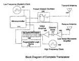
- transmit oscillator 103is configured to respond to a signal from microcontroller 111 so as to emit a short pulse of radio frequency energy at the desired pulse width and center frequency (e.g., two nanoseconds at 6.5 Ghz in the illustrative embodiment) into a transmit antenna 104 .
- a short pulse of radio frequency energyat the desired pulse width and center frequency (e.g., two nanoseconds at 6.5 Ghz in the illustrative embodiment) into a transmit antenna 104 .
- a short pulse of radio frequency energyat the desired pulse width and center frequency (e.g., two nanoseconds at 6.5 Ghz in the illustrative embodiment) into a transmit antenna 104 .
- a short pulse of radio frequency energyat the desired pulse width and center frequency (e.g., two nanoseconds at 6.5 Ghz in the illustrative embodiment) into a transmit antenna 104 .
- such time-gated oscillatorutilizes a silicon bipolar microwave transistor such as an HB
- Receive antenna 105collects energy from this initial transmit pulse both directly when emitted by antenna 104 , as well as from subsequent echo or reflected pulses obtained from scattering of the initial transmit pulse by distant objects.
- Signals collected by receive antenna 105are amplified by low noise, microwave amplifier 106 and detected by detector diode 107 , such as a tunnel diode detector.
- detector diode 107such as a tunnel diode detector.
- the baseband output of detector diode 107is further amplified by video amplifier 108 .
- the signal at the output of video amplifier 108is a pulse that substantially represents the envelope of the radio frequency energy as it is received by antenna 105 . This signal is then passed into high-speed shift register 109 .
- Shift register 109may be implemented by either a programmable logic part, such as an MAX7000B by commercially available from Altera Corporation, or by a custom integrated circuit.
- the high speed shift register 109is clocked by high speed clock 102 .
- the frequency of clock 102determines the spatial resolution of the radar since it determines the sampling rate of the output of video amplifier 108 by the high-speed shift register 109 . In practice, frequencies of 250 MHz are readily achievable for such programmable parts for a sampling interval of four nanoseconds.
- microcontroller 111Once microcontroller 111 has recovered the data of shift register 109 , the register is preferably cleared, and another transmit or trigger pulse issued to initiate another measurement or detection cycle. Software running on microcontroller 111 then processes the received data, possibly taking multiple samples so that averaging can be performed in order to suppress noise.
- microcontroller 111Further samples can be taken with amplifier 106 set to a different gain setting (cf. FIG. 1 ), under the control of microcontroller 111 so that some information about the magnitude of the various features in received signal 201 may also be determined. Once microcontroller 111 has processed the data, it is available for transfer to any display or host computer, which may be appropriately connected.
- a system built or method carried out according to the present inventionmay also enable communication between two similar or substantially identical cooperating transceiver units or systems in a way to geolocate or ascertain the distance between two objects embodying such cooperating transceiver units or systems.
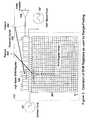
- high speed shift register 109is preferably augmented according to FIG. 3 to include an array 301 having multiple rows, each row being indicative of a shift register sequence and where each row provides a segment of information useful for solving a set of equalities for one or more unknown values.
- FIG. 3illustrates how each bit of shift register 109 is fed to the input of array 301 .
- the contents of shift register 109when transferred to array 301 , shifts vertically in the diagram, and each shift preferably occurs at the rate of system clock 101 .
- an entire row of data from shift register 109is loaded in parallel into a row of array 301 .
- Array 301is preferably implemented with programmable logic as part of programmable logic device 110 . Timing information derived from the respective rows of array 301 is used, as subsequently explained, to determine inter-object range by solving a set of equations or approximated relationships for unknown values.
- a small packet of ‘“1's” and “0's” (missing “1’) valuesis sent during a given number of twelve clock cycles to define a unique identification code. Also, and a small amount of data can similarly be sent in a “data pattern” of ones and zeroes.
- the transmitted coded bit streamwas “1,1,1,1,1,1,0,1,0,1,1,1,1, . . . ”.
- respective transceivers of a selected pair of participating objects among many such objectsmay be identified and engaged to cooperate with each other.
- each packetmay contain multiple bits of data, depending on the details of the desired application.
- the receiver shown in FIG. 3uses conventional logic to ascertain which column “i” contains the valid data, and extracts any data contained therein. Also, the value of “i” corresponding to the appropriate column is noted to ascertain the identification code, if necessary.
- a data packet 403is sent from a first transceiver (Transceiver 1 ) synchronously with a local system clock 401 of the first transceiver, to a second transceiver (Transceiver 2 ), which receives the data packet via the apparatus of FIG. 3 at a slightly later time.
- System clock 401 of the first transceiver, and system clock 402 of the second transceiverboth correspond to system clock 101 in each respective cooperating transceiver.
- the received packet 404 at the second transceiveris not necessarily synchronous with receiver system clock 402 .
- the apparatus of FIG. 3is used to determine the offset time 407 , corresponding to bit “i” in FIG. 3 .
- T 407T 405 + T 406 (1)
- the propagation timerepresents the time-of-flight between the two transceivers; and thus, when multiplied by the speed of light constant “c”, gives the distance between them.
- the propagation time T 405cannot be simply extracted from this measurement alone.
- unknown propagation time T 405can be calculated.
- the remote transceiver unit of Transceiver 2transmits a packet 408 back to the local unit of Transceiver 1 .
- This delay time 412(referenced to the start of the packet at Transceiver 1 ) is referred to as T 412 .
- the second transmitted packet 408experiences a propagation time T 405 ′, which is substantially identical to propagation time T 405 , since very little physical movement could have occurred in time T 412 .
- time T 412is typically one hundred microseconds but may be somewhat less or possibly greater, depending upon the amount of data contained in packet 408 .
- time T 412is typically one hundred microseconds but may be somewhat less or possibly greater, depending upon the amount of data contained in packet 408 .
- T 405′T 405 .
- Packet 408is now received by the first transceiver as packet 409 , and a similar determination of its offset “i” with respect to system clock 401 is made in order to obtain offset time T 410 .
- offset time T 410is the sum of the (Transceiver 1 ) system clock cycle time T 411 , minus the skew time T 406′ , plus the propagation time T 405′ . That is:
- T 410T 411 ⁇ T 406′ +T 405′ (2)
- the actual measured quantitiesare offset time T 407 in Transceiver 2 for the initial packet; and offset time T 410 in Transceiver 1 for the response packet. Also, the (Transceiver 1 ) clock cycle time T 411 is known very accurately. Furthermore, by including the measurement T 407 in the return packet information 408 , the cooperating Transceiver 1 will have subsequently obtained information about that previous offset measurement result at cooperating Transceiver 2 .
- T 407 +T 410( T 405 +T 405′ )+( T 406 ⁇ T 406′ )+ T 411 (3)
- T 4050.5*( T 407 +T 410 ⁇ T 411 ) (4)
- a first order correctioncan be applied by simply assuming that the dominant error is caused by a frequency offset between system clock signals 401 and 402 .
- a constant frequency offsetresults in a skew that grows linearly with time.
- the skew at the second packet transmission(packet 408 to packet 409 ) differs from that at the first packet transmission (packet 403 to packet 404 ) by some amount which is proportional to the delay time T 412 . That is,
- System clock frequency errorcan thus be compensated to first order.
- Higher order correctionscan also easily be implemented by making additional measurements and fitting the results to the appropriate nonlinear model for skew drift by techniques well known in the art of instrumentation.
- the inventionmay be extended to geolocation. Assuming one of two participating object is moving or two intercommunicating pairs of participating objects are simultaneously engaged, a relative distance measurement may be obtained at multiple positions of a moving first object relative to a fixed target or at each of multiple stationary objects relative to a fixed target. The resulting distance measurements then provide a basis for geolocating the target simply by employing conventional triangulation algorithms. Ambiguities may be resolved by providing additional distance measurements.
- the principles of the inventionmay even be extended to spatially determine relative range, direction, and azimuth in order to locate an object in free space. Equipping a first participating object with a geolocation system that ascertains true positioning, e.g, GPS, further enables true geopositioning of a participating target.
Landscapes
- Engineering & Computer Science (AREA)
- Radar, Positioning & Navigation (AREA)
- Remote Sensing (AREA)
- Computer Networks & Wireless Communication (AREA)
- Physics & Mathematics (AREA)
- General Physics & Mathematics (AREA)
- Radar Systems Or Details Thereof (AREA)
Abstract
Description


Claims (43)
Priority Applications (1)
| Application Number | Priority Date | Filing Date | Title |
|---|---|---|---|
| US10/385,658US6812884B2 (en) | 2003-03-12 | 2003-03-12 | Transceiver system and method utilizing nanosecond pulses |
Applications Claiming Priority (1)
| Application Number | Priority Date | Filing Date | Title |
|---|---|---|---|
| US10/385,658US6812884B2 (en) | 2003-03-12 | 2003-03-12 | Transceiver system and method utilizing nanosecond pulses |
Publications (2)
| Publication Number | Publication Date |
|---|---|
| US20040178947A1 US20040178947A1 (en) | 2004-09-16 |
| US6812884B2true US6812884B2 (en) | 2004-11-02 |
Family
ID=32961540
Family Applications (1)
| Application Number | Title | Priority Date | Filing Date |
|---|---|---|---|
| US10/385,658Expired - LifetimeUS6812884B2 (en) | 2003-03-12 | 2003-03-12 | Transceiver system and method utilizing nanosecond pulses |
Country Status (1)
| Country | Link |
|---|---|
| US (1) | US6812884B2 (en) |
Cited By (48)
| Publication number | Priority date | Publication date | Assignee | Title |
|---|---|---|---|---|
| US20050128131A1 (en)* | 2003-03-10 | 2005-06-16 | Rafael-Armament Development Authority, Ltd. | Friend/foe identification system for a battlefield |
| US20050215269A1 (en)* | 2004-02-17 | 2005-09-29 | Jadi Inc. | Navigation system |
| US20060080004A1 (en)* | 2004-04-29 | 2006-04-13 | Jadi Inc. | Self-leveling laser horizon for navigation guidance |
| US20060136016A1 (en)* | 2004-12-16 | 2006-06-22 | Samsung Electronics Co., Ltd. | Synchronization method and apparatus and location awareness method and apparatus in chaotic communication system |
| US20060184376A1 (en)* | 2005-02-11 | 2006-08-17 | Nortel Networks Limited | Use of location awareness to detect potentially supsicious motion or presence of equipment in a healthcare environment |
| US20060181243A1 (en)* | 2005-02-11 | 2006-08-17 | Nortel Networks Limited | Use of location awareness to facilitate clinician-charger interaction in a healthcare environment |
| US20060185005A1 (en)* | 2005-02-11 | 2006-08-17 | Nortel Networks Limited | Use of location awareness to transfer communications sessions between terminals in a healthcare environment |
| US20060214840A1 (en)* | 2005-03-25 | 2006-09-28 | Samsung Electronics Co., Ltd. | Method and apparatus for measuring distance using low clock rate signal |
| US20060236373A1 (en)* | 2005-02-11 | 2006-10-19 | Nortel Networks Limited | Use of location awareness to establish and suspend communications sessions in a healthcare environment |
| US20060240771A1 (en)* | 2005-02-11 | 2006-10-26 | Nortel Networks Limited | Use of location awareness ot establish communications with a target clinician in a healthcare environment |
| US20070004389A1 (en)* | 2005-02-11 | 2007-01-04 | Nortel Networks Limited | Method and system for enhancing collaboration |
| US20070182587A1 (en)* | 2003-05-22 | 2007-08-09 | Christian Danz | Method and device for detecting objects in the surroundings of a vehicle |
| US20080234930A1 (en)* | 2007-03-21 | 2008-09-25 | Jadi Inc. | Navigation unit and base station |
| US20080262669A1 (en)* | 2006-09-22 | 2008-10-23 | Jadi, Inc. | Autonomous vehicle controller |
| US20090143045A1 (en)* | 2007-12-04 | 2009-06-04 | Nortel Networks Limited | Systems and methods for facilitating a first response mission at an incident scene |
| US20090140043A1 (en)* | 2007-12-03 | 2009-06-04 | Nortel Networks Limited | Portable memory module with wireless emitter to facilitate the provision of location-dependent services |
| US20090147940A1 (en)* | 2007-12-05 | 2009-06-11 | Nortel Network Limited | Methods and systems for managing communication requests in an institutional setting such as a healthcare facility |
| US20090201169A1 (en)* | 2008-02-07 | 2009-08-13 | Mark Iv Industries Corp. | Real-Time Location Systems and Methods |
| US20090224876A1 (en)* | 2008-03-06 | 2009-09-10 | Gm Global Technology Operations, Inc. | Multiple transceiver synchronous communication system |
| US20100190517A1 (en)* | 2007-08-03 | 2010-07-29 | Cornell University | Pulse coupled oscillator synchronization for wireless communications |
| US20100277248A1 (en)* | 2009-05-01 | 2010-11-04 | Mcclain Jr Ross A | Systems and methods for generating pulsed output signals using a gated RF oscillator circuit |
| US20100277280A1 (en)* | 2009-05-01 | 2010-11-04 | Burkart Scott M | Systems and methods for relaying information with RFID tags |
| US20100277283A1 (en)* | 2009-05-01 | 2010-11-04 | Burkart Scott M | Systems and methods for RFID tag operation |
| US20110071761A1 (en)* | 2009-09-18 | 2011-03-24 | Charles Arnold Cummings | Holistic cybernetic vehicle control |
| US20110133990A1 (en)* | 2009-12-09 | 2011-06-09 | Kent Kahle | System for determining position in a work space |
| US7966008B2 (en) | 2005-02-11 | 2011-06-21 | Avaya Inc. | Use of location awareness to control radio frequency interference in a healthcare environment |
| US20110163844A1 (en)* | 2008-09-01 | 2011-07-07 | Gerd Reime | Identification element having an optical transponder |
| US8050939B2 (en) | 2005-02-11 | 2011-11-01 | Avaya Inc. | Methods and systems for use in the provision of services in an institutional setting such as a healthcare facility |
| US8180650B2 (en) | 2005-02-11 | 2012-05-15 | Avaya Inc. | Use of location awareness to request assistance for a medical event occurring in a healthcare environment |
| US8368513B2 (en) | 2009-05-01 | 2013-02-05 | L-3 Communications Integrated Systems L.P. | Data separation in high density environments |
| US8456282B2 (en) | 2009-05-01 | 2013-06-04 | L-3 Communications Integrated Systems L.P. | Synchronization of devices in a RFID communications environment |
| US8700202B2 (en) | 2010-11-30 | 2014-04-15 | Trimble Navigation Limited | System for positioning a tool in a work space |
| US9180357B2 (en) | 2013-06-06 | 2015-11-10 | Zih Corp. | Multiple antenna interference rejection in ultra-wideband real time locating systems |
| US9517417B2 (en) | 2013-06-06 | 2016-12-13 | Zih Corp. | Method, apparatus, and computer program product for performance analytics determining participant statistical data and game status data |
| US9626616B2 (en) | 2014-06-05 | 2017-04-18 | Zih Corp. | Low-profile real-time location system tag |
| US9661455B2 (en) | 2014-06-05 | 2017-05-23 | Zih Corp. | Method, apparatus, and computer program product for real time location system referencing in physically and radio frequency challenged environments |
| US9668164B2 (en) | 2014-06-05 | 2017-05-30 | Zih Corp. | Receiver processor for bandwidth management of a multiple receiver real-time location system (RTLS) |
| US9699278B2 (en) | 2013-06-06 | 2017-07-04 | Zih Corp. | Modular location tag for a real time location system network |
| US9715005B2 (en) | 2013-06-06 | 2017-07-25 | Zih Corp. | Method, apparatus, and computer program product improving real time location systems with multiple location technologies |
| US9759803B2 (en) | 2014-06-06 | 2017-09-12 | Zih Corp. | Method, apparatus, and computer program product for employing a spatial association model in a real time location system |
| US9854558B2 (en) | 2014-06-05 | 2017-12-26 | Zih Corp. | Receiver processor for adaptive windowing and high-resolution TOA determination in a multiple receiver target location system |
| US9953195B2 (en) | 2014-06-05 | 2018-04-24 | Zih Corp. | Systems, apparatus and methods for variable rate ultra-wideband communications |
| US10261169B2 (en) | 2014-06-05 | 2019-04-16 | Zebra Technologies Corporation | Method for iterative target location in a multiple receiver target location system |
| US10437658B2 (en) | 2013-06-06 | 2019-10-08 | Zebra Technologies Corporation | Method, apparatus, and computer program product for collecting and displaying sporting event data based on real time data for proximity and movement of objects |
| US10509099B2 (en) | 2013-06-06 | 2019-12-17 | Zebra Technologies Corporation | Method, apparatus and computer program product improving real time location systems with multiple location technologies |
| US10609762B2 (en) | 2013-06-06 | 2020-03-31 | Zebra Technologies Corporation | Method, apparatus, and computer program product improving backhaul of sensor and other data to real time location system network |
| US11391571B2 (en) | 2014-06-05 | 2022-07-19 | Zebra Technologies Corporation | Method, apparatus, and computer program for enhancement of event visualizations based on location data |
| US11423464B2 (en) | 2013-06-06 | 2022-08-23 | Zebra Technologies Corporation | Method, apparatus, and computer program product for enhancement of fan experience based on location data |
Families Citing this family (5)
| Publication number | Priority date | Publication date | Assignee | Title |
|---|---|---|---|---|
| US7274323B2 (en)* | 2003-12-10 | 2007-09-25 | Honeywell International Inc. | Remote phase synchronization using a low-bandwidth timing referencer |
| US7359039B2 (en) | 2005-07-13 | 2008-04-15 | Mariusz Kloza | Device for precise distance measurement |
| US7450069B2 (en)* | 2006-02-27 | 2008-11-11 | Olympus Corporation Technology Of America | Ranging system and method |
| CN102147460B (en)* | 2010-02-10 | 2014-05-14 | 中国科学院电子学研究所 | System and method for receiving ultra wide band pulsed radar |
| CN117279083A (en)* | 2022-06-15 | 2023-12-22 | 华为技术有限公司 | Bluetooth time setting method, readable medium and electronic equipment |
Citations (16)
| Publication number | Priority date | Publication date | Assignee | Title |
|---|---|---|---|---|
| US3680091A (en)* | 1970-07-21 | 1972-07-25 | Collins Radio Co | Pulse train framing and intermediate pulse spacing accuracy test circuit |
| US3800440A (en)* | 1972-09-01 | 1974-04-02 | Singer Co | Radio identification system simulator (iff) |
| US3801982A (en)* | 1968-04-22 | 1974-04-02 | Sanders Associates Inc | Post storage range and doppler correlation method and apparatus |
| US3825929A (en)* | 1972-12-26 | 1974-07-23 | Tull Aviation Corp | Compatible split-band distance measuring method and apparatus |
| US3887918A (en)* | 1973-05-09 | 1975-06-03 | Itt | Multi-level digital coincidence detection |
| US3900868A (en)* | 1974-03-22 | 1975-08-19 | Sperry Rand Corp | Apparatus and method for pulse tracker ranging equipment with increased resolution |
| US3979752A (en)* | 1974-07-12 | 1976-09-07 | Thomson-Csf | Pulse-type radar with modulated carrier frequency |
| US4005417A (en)* | 1975-08-14 | 1977-01-25 | Raytheon Company | Frequency spectrum analyzer |
| US4153366A (en)* | 1977-06-21 | 1979-05-08 | The Charles Stark Draper Laboratory, Inc. | Rangefinding system |
| US4169264A (en)* | 1978-07-03 | 1979-09-25 | Sperry Rand Corporation | Synchronous digital delay line pulse spacing decoder |
| US4197535A (en)* | 1977-06-29 | 1980-04-08 | Siemens Aktiengesellschaft | Pulse radar device having pulsed storage devices arranged in the signal analysis component |
| US4242683A (en)* | 1977-05-26 | 1980-12-30 | Raytheon Company | Signal processor |
| US4395712A (en)* | 1981-01-27 | 1983-07-26 | General Signal Corp. | Linear detection of a DME signal |
| US4438435A (en)* | 1980-07-23 | 1984-03-20 | International Standard Electric Corporation | Two-way ranging system |
| US5148175A (en)* | 1991-07-05 | 1992-09-15 | Sperry Marine Inc. | High resolution variable range gate generator with programmable timing |
| US5532701A (en)* | 1992-05-21 | 1996-07-02 | Alcatel Italia S.P.A. | Arrangement for comparing two temporally separated bursts of signal at two different frequencies |
- 2003
- 2003-03-12USUS10/385,658patent/US6812884B2/ennot_activeExpired - Lifetime
Patent Citations (16)
| Publication number | Priority date | Publication date | Assignee | Title |
|---|---|---|---|---|
| US3801982A (en)* | 1968-04-22 | 1974-04-02 | Sanders Associates Inc | Post storage range and doppler correlation method and apparatus |
| US3680091A (en)* | 1970-07-21 | 1972-07-25 | Collins Radio Co | Pulse train framing and intermediate pulse spacing accuracy test circuit |
| US3800440A (en)* | 1972-09-01 | 1974-04-02 | Singer Co | Radio identification system simulator (iff) |
| US3825929A (en)* | 1972-12-26 | 1974-07-23 | Tull Aviation Corp | Compatible split-band distance measuring method and apparatus |
| US3887918A (en)* | 1973-05-09 | 1975-06-03 | Itt | Multi-level digital coincidence detection |
| US3900868A (en)* | 1974-03-22 | 1975-08-19 | Sperry Rand Corp | Apparatus and method for pulse tracker ranging equipment with increased resolution |
| US3979752A (en)* | 1974-07-12 | 1976-09-07 | Thomson-Csf | Pulse-type radar with modulated carrier frequency |
| US4005417A (en)* | 1975-08-14 | 1977-01-25 | Raytheon Company | Frequency spectrum analyzer |
| US4242683A (en)* | 1977-05-26 | 1980-12-30 | Raytheon Company | Signal processor |
| US4153366A (en)* | 1977-06-21 | 1979-05-08 | The Charles Stark Draper Laboratory, Inc. | Rangefinding system |
| US4197535A (en)* | 1977-06-29 | 1980-04-08 | Siemens Aktiengesellschaft | Pulse radar device having pulsed storage devices arranged in the signal analysis component |
| US4169264A (en)* | 1978-07-03 | 1979-09-25 | Sperry Rand Corporation | Synchronous digital delay line pulse spacing decoder |
| US4438435A (en)* | 1980-07-23 | 1984-03-20 | International Standard Electric Corporation | Two-way ranging system |
| US4395712A (en)* | 1981-01-27 | 1983-07-26 | General Signal Corp. | Linear detection of a DME signal |
| US5148175A (en)* | 1991-07-05 | 1992-09-15 | Sperry Marine Inc. | High resolution variable range gate generator with programmable timing |
| US5532701A (en)* | 1992-05-21 | 1996-07-02 | Alcatel Italia S.P.A. | Arrangement for comparing two temporally separated bursts of signal at two different frequencies |
Cited By (104)
| Publication number | Priority date | Publication date | Assignee | Title |
|---|---|---|---|---|
| US20050128131A1 (en)* | 2003-03-10 | 2005-06-16 | Rafael-Armament Development Authority, Ltd. | Friend/foe identification system for a battlefield |
| US7046186B2 (en)* | 2003-03-10 | 2006-05-16 | Rafael-Armament Development Authority, Ltd. | Friend/foe identification system for a battlefield |
| US7729856B2 (en)* | 2003-05-22 | 2010-06-01 | Robert Bosch Gmbh | Method and device for detecting objects in the surroundings of a vehicle |
| US20070182587A1 (en)* | 2003-05-22 | 2007-08-09 | Christian Danz | Method and device for detecting objects in the surroundings of a vehicle |
| US20050215269A1 (en)* | 2004-02-17 | 2005-09-29 | Jadi Inc. | Navigation system |
| US7983694B2 (en) | 2004-02-17 | 2011-07-19 | Nav-Track, Inc. | Target and base station for a navigation system |
| US8010133B2 (en) | 2004-02-17 | 2011-08-30 | Nav-Track, Inc. | Navigation system |
| US20080103696A1 (en)* | 2004-02-17 | 2008-05-01 | Jadi Inc. | Navigation system |
| US7403783B2 (en) | 2004-02-17 | 2008-07-22 | Jadi, Inc. | Navigation system |
| US20080167051A1 (en)* | 2004-02-17 | 2008-07-10 | Jadi Inc. | Navigation system |
| US20060080004A1 (en)* | 2004-04-29 | 2006-04-13 | Jadi Inc. | Self-leveling laser horizon for navigation guidance |
| US7908041B2 (en) | 2004-04-29 | 2011-03-15 | Munro & Associates, Inc. | Self-leveling laser horizon for navigation guidance |
| US20060136016A1 (en)* | 2004-12-16 | 2006-06-22 | Samsung Electronics Co., Ltd. | Synchronization method and apparatus and location awareness method and apparatus in chaotic communication system |
| US7801743B2 (en) | 2005-02-11 | 2010-09-21 | Avaya Inc. | Use of location awareness of establish communications with a target clinician in a healthcare environment |
| US8929528B2 (en) | 2005-02-11 | 2015-01-06 | Rockstar Consortium Us Lp | Method and system for enhancing collaboration |
| US20060240771A1 (en)* | 2005-02-11 | 2006-10-26 | Nortel Networks Limited | Use of location awareness ot establish communications with a target clinician in a healthcare environment |
| US20060184376A1 (en)* | 2005-02-11 | 2006-08-17 | Nortel Networks Limited | Use of location awareness to detect potentially supsicious motion or presence of equipment in a healthcare environment |
| US7707044B2 (en) | 2005-02-11 | 2010-04-27 | Avaya Inc. | Use of location awareness to transfer communications sessions between terminals in a healthcare environment |
| US7676380B2 (en) | 2005-02-11 | 2010-03-09 | Nortel Networks Limited | Use of location awareness to establish and suspend communications sessions in a healthcare environment |
| US7966008B2 (en) | 2005-02-11 | 2011-06-21 | Avaya Inc. | Use of location awareness to control radio frequency interference in a healthcare environment |
| US8050939B2 (en) | 2005-02-11 | 2011-11-01 | Avaya Inc. | Methods and systems for use in the provision of services in an institutional setting such as a healthcare facility |
| US20060181243A1 (en)* | 2005-02-11 | 2006-08-17 | Nortel Networks Limited | Use of location awareness to facilitate clinician-charger interaction in a healthcare environment |
| US8180650B2 (en) | 2005-02-11 | 2012-05-15 | Avaya Inc. | Use of location awareness to request assistance for a medical event occurring in a healthcare environment |
| US20060185005A1 (en)* | 2005-02-11 | 2006-08-17 | Nortel Networks Limited | Use of location awareness to transfer communications sessions between terminals in a healthcare environment |
| US20070004389A1 (en)* | 2005-02-11 | 2007-01-04 | Nortel Networks Limited | Method and system for enhancing collaboration |
| US20060236373A1 (en)* | 2005-02-11 | 2006-10-19 | Nortel Networks Limited | Use of location awareness to establish and suspend communications sessions in a healthcare environment |
| US7518546B2 (en)* | 2005-03-25 | 2009-04-14 | Samsung Electronics Co., Ltd. | Method and apparatus for measuring distance using low clock rate signal |
| US20060214840A1 (en)* | 2005-03-25 | 2006-09-28 | Samsung Electronics Co., Ltd. | Method and apparatus for measuring distance using low clock rate signal |
| US20080262669A1 (en)* | 2006-09-22 | 2008-10-23 | Jadi, Inc. | Autonomous vehicle controller |
| US8214147B2 (en) | 2007-03-21 | 2012-07-03 | Nav-Track, Inc. | Navigation unit and base station |
| US20080234930A1 (en)* | 2007-03-21 | 2008-09-25 | Jadi Inc. | Navigation unit and base station |
| US20100190517A1 (en)* | 2007-08-03 | 2010-07-29 | Cornell University | Pulse coupled oscillator synchronization for wireless communications |
| US8543068B2 (en)* | 2007-08-03 | 2013-09-24 | Cornell University | Pulse coupled oscillator synchronization for wireless communications |
| US8727216B2 (en) | 2007-12-03 | 2014-05-20 | Apple Inc. | Portable memory module with wireless emitter to facilitate the provision of location-dependent services |
| US20090140043A1 (en)* | 2007-12-03 | 2009-06-04 | Nortel Networks Limited | Portable memory module with wireless emitter to facilitate the provision of location-dependent services |
| US20090140851A1 (en)* | 2007-12-04 | 2009-06-04 | Nortel Networks Limited | Systems and methods for facilitating a first response mission at an incident scene using patient monitoring |
| US20090140923A1 (en)* | 2007-12-04 | 2009-06-04 | Nortel Networks Limited | Systems and methods for facilitating a first response mission at an incident scene using precision location |
| US8054177B2 (en) | 2007-12-04 | 2011-11-08 | Avaya Inc. | Systems and methods for facilitating a first response mission at an incident scene using patient monitoring |
| US20090143045A1 (en)* | 2007-12-04 | 2009-06-04 | Nortel Networks Limited | Systems and methods for facilitating a first response mission at an incident scene |
| US8040246B2 (en) | 2007-12-04 | 2011-10-18 | Avaya Inc. | Systems and methods for facilitating a first response mission at an incident scene |
| US7999741B2 (en) | 2007-12-04 | 2011-08-16 | Avaya Inc. | Systems and methods for facilitating a first response mission at an incident scene using precision location |
| US8589176B2 (en) | 2007-12-05 | 2013-11-19 | Avaya, Inc. | Methods and systems for managing communication requests in an institutional setting such as a healthcare facility |
| US20090147940A1 (en)* | 2007-12-05 | 2009-06-11 | Nortel Network Limited | Methods and systems for managing communication requests in an institutional setting such as a healthcare facility |
| US20090201169A1 (en)* | 2008-02-07 | 2009-08-13 | Mark Iv Industries Corp. | Real-Time Location Systems and Methods |
| US20090224876A1 (en)* | 2008-03-06 | 2009-09-10 | Gm Global Technology Operations, Inc. | Multiple transceiver synchronous communication system |
| US8193915B2 (en)* | 2008-03-06 | 2012-06-05 | GM Global Technology Operations LLC | Multiple transceiver synchronous communication system |
| US20110163844A1 (en)* | 2008-09-01 | 2011-07-07 | Gerd Reime | Identification element having an optical transponder |
| US10229351B2 (en)* | 2008-09-01 | 2019-03-12 | Gerd Reime | Identification element having an optical transponder |
| US8456282B2 (en) | 2009-05-01 | 2013-06-04 | L-3 Communications Integrated Systems L.P. | Synchronization of devices in a RFID communications environment |
| US8368513B2 (en) | 2009-05-01 | 2013-02-05 | L-3 Communications Integrated Systems L.P. | Data separation in high density environments |
| US20100277248A1 (en)* | 2009-05-01 | 2010-11-04 | Mcclain Jr Ross A | Systems and methods for generating pulsed output signals using a gated RF oscillator circuit |
| US8665035B2 (en) | 2009-05-01 | 2014-03-04 | L-3 Communications Integrated Systems Lp | Systems and methods for generating pulsed output signals using a gated RF oscillator circuit |
| US20100277280A1 (en)* | 2009-05-01 | 2010-11-04 | Burkart Scott M | Systems and methods for relaying information with RFID tags |
| US20100277283A1 (en)* | 2009-05-01 | 2010-11-04 | Burkart Scott M | Systems and methods for RFID tag operation |
| US8731815B2 (en) | 2009-09-18 | 2014-05-20 | Charles Arnold Cummings | Holistic cybernetic vehicle control |
| US20110071761A1 (en)* | 2009-09-18 | 2011-03-24 | Charles Arnold Cummings | Holistic cybernetic vehicle control |
| US9585598B2 (en) | 2009-12-09 | 2017-03-07 | Trimble Inc. | System for determining position in a work space |
| US8319687B2 (en) | 2009-12-09 | 2012-11-27 | Trimble Navigation Limited | System for determining position in a work space |
| US20110133990A1 (en)* | 2009-12-09 | 2011-06-09 | Kent Kahle | System for determining position in a work space |
| US8700202B2 (en) | 2010-11-30 | 2014-04-15 | Trimble Navigation Limited | System for positioning a tool in a work space |
| US9760078B2 (en) | 2010-11-30 | 2017-09-12 | Trimble Inc. | System for positioning a tool in a work space |
| US9742450B2 (en) | 2013-06-06 | 2017-08-22 | Zih Corp. | Method, apparatus, and computer program product improving registration with real time location services |
| US10212262B2 (en) | 2013-06-06 | 2019-02-19 | Zebra Technologies Corporation | Modular location tag for a real time location system network |
| US9602152B2 (en) | 2013-06-06 | 2017-03-21 | Zih Corp. | Method, apparatus, and computer program product for determining play events and outputting events based on real-time data for proximity, movement of objects, and audio data |
| US12360837B2 (en) | 2013-06-06 | 2025-07-15 | Zebra Technologies Corporation | Method, apparatus, and computer program product for collecting and displaying sporting event data based on real time data for proximity and movement of objects |
| US11423464B2 (en) | 2013-06-06 | 2022-08-23 | Zebra Technologies Corporation | Method, apparatus, and computer program product for enhancement of fan experience based on location data |
| US11287511B2 (en) | 2013-06-06 | 2022-03-29 | Zebra Technologies Corporation | Method, apparatus, and computer program product improving real time location systems with multiple location technologies |
| US9667287B2 (en) | 2013-06-06 | 2017-05-30 | Zih Corp. | Multiple antenna interference rejection in ultra-wideband real time locating systems |
| US9698841B2 (en) | 2013-06-06 | 2017-07-04 | Zih Corp. | Method and apparatus for associating radio frequency identification tags with participants |
| US9699278B2 (en) | 2013-06-06 | 2017-07-04 | Zih Corp. | Modular location tag for a real time location system network |
| US9715005B2 (en) | 2013-06-06 | 2017-07-25 | Zih Corp. | Method, apparatus, and computer program product improving real time location systems with multiple location technologies |
| US9531415B2 (en) | 2013-06-06 | 2016-12-27 | Zih Corp. | Systems and methods for activity determination based on human frame |
| US9517417B2 (en) | 2013-06-06 | 2016-12-13 | Zih Corp. | Method, apparatus, and computer program product for performance analytics determining participant statistical data and game status data |
| US11023303B2 (en) | 2013-06-06 | 2021-06-01 | Zebra Technologies Corporation | Methods and apparatus to correlate unique identifiers and tag-individual correlators based on status change indications |
| US9839809B2 (en) | 2013-06-06 | 2017-12-12 | Zih Corp. | Method, apparatus, and computer program product for determining play events and outputting events based on real-time data for proximity, movement of objects, and audio data |
| US10778268B2 (en) | 2013-06-06 | 2020-09-15 | Zebra Technologies Corporation | Method, apparatus, and computer program product for performance analytics determining play models and outputting events based on real-time data for proximity and movement of objects |
| US10707908B2 (en) | 2013-06-06 | 2020-07-07 | Zebra Technologies Corporation | Method, apparatus, and computer program product for evaluating performance based on real-time data for proximity and movement of objects |
| US9882592B2 (en) | 2013-06-06 | 2018-01-30 | Zih Corp. | Method, apparatus, and computer program product for tag and individual correlation |
| US10609762B2 (en) | 2013-06-06 | 2020-03-31 | Zebra Technologies Corporation | Method, apparatus, and computer program product improving backhaul of sensor and other data to real time location system network |
| US10509099B2 (en) | 2013-06-06 | 2019-12-17 | Zebra Technologies Corporation | Method, apparatus and computer program product improving real time location systems with multiple location technologies |
| US9985672B2 (en) | 2013-06-06 | 2018-05-29 | Zih Corp. | Method, apparatus, and computer program product for evaluating performance based on real-time data for proximity and movement of objects |
| US10050650B2 (en) | 2013-06-06 | 2018-08-14 | Zih Corp. | Method, apparatus, and computer program product improving registration with real time location services |
| US9571143B2 (en) | 2013-06-06 | 2017-02-14 | Zih Corp. | Interference rejection in ultra-wideband real time locating systems |
| US10218399B2 (en) | 2013-06-06 | 2019-02-26 | Zebra Technologies Corporation | Systems and methods for activity determination based on human frame |
| US9180357B2 (en) | 2013-06-06 | 2015-11-10 | Zih Corp. | Multiple antenna interference rejection in ultra-wideband real time locating systems |
| US10437658B2 (en) | 2013-06-06 | 2019-10-08 | Zebra Technologies Corporation | Method, apparatus, and computer program product for collecting and displaying sporting event data based on real time data for proximity and movement of objects |
| US10421020B2 (en) | 2013-06-06 | 2019-09-24 | Zebra Technologies Corporation | Method, apparatus, and computer program product for performance analytics determining participant statistical data and game status data |
| US10333568B2 (en) | 2013-06-06 | 2019-06-25 | Zebra Technologies Corporation | Method and apparatus for associating radio frequency identification tags with participants |
| US9854558B2 (en) | 2014-06-05 | 2017-12-26 | Zih Corp. | Receiver processor for adaptive windowing and high-resolution TOA determination in a multiple receiver target location system |
| US10942248B2 (en) | 2014-06-05 | 2021-03-09 | Zebra Technologies Corporation | Method, apparatus, and computer program product for real time location system referencing in physically and radio frequency challenged environments |
| US10261169B2 (en) | 2014-06-05 | 2019-04-16 | Zebra Technologies Corporation | Method for iterative target location in a multiple receiver target location system |
| US9953196B2 (en) | 2014-06-05 | 2018-04-24 | Zih Corp. | System, apparatus and methods for variable rate ultra-wideband communications |
| US10520582B2 (en) | 2014-06-05 | 2019-12-31 | Zebra Technologies Corporation | Method for iterative target location in a multiple receiver target location system |
| US9626616B2 (en) | 2014-06-05 | 2017-04-18 | Zih Corp. | Low-profile real-time location system tag |
| US10285157B2 (en) | 2014-06-05 | 2019-05-07 | Zebra Technologies Corporation | Receiver processor for adaptive windowing and high-resolution TOA determination in a multiple receiver target location system |
| US9953195B2 (en) | 2014-06-05 | 2018-04-24 | Zih Corp. | Systems, apparatus and methods for variable rate ultra-wideband communications |
| US10310052B2 (en) | 2014-06-05 | 2019-06-04 | Zebra Technologies Corporation | Method, apparatus, and computer program product for real time location system referencing in physically and radio frequency challenged environments |
| US9864946B2 (en) | 2014-06-05 | 2018-01-09 | Zih Corp. | Low-profile real-time location system tag |
| US9661455B2 (en) | 2014-06-05 | 2017-05-23 | Zih Corp. | Method, apparatus, and computer program product for real time location system referencing in physically and radio frequency challenged environments |
| US11391571B2 (en) | 2014-06-05 | 2022-07-19 | Zebra Technologies Corporation | Method, apparatus, and computer program for enhancement of event visualizations based on location data |
| US9668164B2 (en) | 2014-06-05 | 2017-05-30 | Zih Corp. | Receiver processor for bandwidth management of a multiple receiver real-time location system (RTLS) |
| US11156693B2 (en) | 2014-06-06 | 2021-10-26 | Zebra Technologies Corporation | Method, apparatus, and computer program product for employing a spatial association model in a real time location system |
| US9759803B2 (en) | 2014-06-06 | 2017-09-12 | Zih Corp. | Method, apparatus, and computer program product for employing a spatial association model in a real time location system |
| US10591578B2 (en) | 2014-06-06 | 2020-03-17 | Zebra Technologies Corporation | Method, apparatus, and computer program product for employing a spatial association model in a real time location system |
Also Published As
| Publication number | Publication date |
|---|---|
| US20040178947A1 (en) | 2004-09-16 |
Similar Documents
| Publication | Publication Date | Title |
|---|---|---|
| US6812884B2 (en) | Transceiver system and method utilizing nanosecond pulses | |
| US10285157B2 (en) | Receiver processor for adaptive windowing and high-resolution TOA determination in a multiple receiver target location system | |
| US11656315B2 (en) | System and method for ultrawideband position location | |
| US6239741B1 (en) | UWB dual tunnel diode detector for object detection, measurement, or avoidance | |
| US9791550B2 (en) | Frequency-Modulated-Continuous-Wave (FMCW) radar with timing synchronization | |
| US6424916B2 (en) | Environmental location system | |
| US7095368B1 (en) | Method and apparatus for combining measurements and determining clock offsets between different satellite positioning systems | |
| KR100671283B1 (en) | Asynchronous wireless positioning system and method using sequential transmission and reception | |
| US7504992B2 (en) | Wireless system using continuous wave phase measurement for high-precision distance measurement | |
| JP4963240B2 (en) | Radar equipment | |
| US20090273518A1 (en) | Associating a Universal Time with Received Signal | |
| US9031811B2 (en) | System and method for pulse-echo ranging | |
| CN103293947A (en) | Satellite-ground laser time comparison system | |
| JP2009270827A (en) | Multi-static radar system | |
| US20120163421A1 (en) | Location system | |
| CN115552275A (en) | Systems, devices, and/or methods for providing wireless communication and location tags | |
| US7205930B2 (en) | Instantaneous 3—D target location resolution utilizing only bistatic range measurement in a multistatic system | |
| WO2021033379A1 (en) | Distance measurement device and distance measurement method | |
| US20110260910A1 (en) | System and method for microwave ranging to a target in presence of clutter and multi-path effects | |
| WO2007023446A1 (en) | Determining position of a portable device | |
| US8742978B2 (en) | Method and arrangement for measuring delay of a signal between two stations of the arrangement | |
| Brooks et al. | A review of position tracking methods | |
| US8054863B2 (en) | Ranging system and method | |
| JP4937805B2 (en) | RADIO COMMUNICATION DEVICE AND DISTANCE MEASURING METHOD IN RADIO COMMUNICATION DEVICE | |
| CN203338015U (en) | A Star-to-Earth Laser Time Comparison System |
Legal Events
| Date | Code | Title | Description |
|---|---|---|---|
| STCF | Information on status: patent grant | Free format text:PATENTED CASE | |
| FPAY | Fee payment | Year of fee payment:4 | |
| FPAY | Fee payment | Year of fee payment:8 | |
| AS | Assignment | Owner name:ZIH CORP., ILLINOIS Free format text:ASSIGNMENT OF ASSIGNORS INTEREST;ASSIGNOR:MULTISPECTRAL SOLUTIONS, INC.;REEL/FRAME:032785/0084 Effective date:20140429 | |
| AS | Assignment | Owner name:MORGAN STANLEY SENIOR FUNDING, INC. AS THE COLLATERAL AGENT, MARYLAND Free format text:SECURITY AGREEMENT;ASSIGNORS:ZIH CORP.;LASER BAND, LLC;ZEBRA ENTERPRISE SOLUTIONS CORP.;AND OTHERS;REEL/FRAME:034114/0270 Effective date:20141027 Owner name:MORGAN STANLEY SENIOR FUNDING, INC. AS THE COLLATE Free format text:SECURITY AGREEMENT;ASSIGNORS:ZIH CORP.;LASER BAND, LLC;ZEBRA ENTERPRISE SOLUTIONS CORP.;AND OTHERS;REEL/FRAME:034114/0270 Effective date:20141027 | |
| FEPP | Fee payment procedure | Free format text:PAT HOLDER NO LONGER CLAIMS SMALL ENTITY STATUS, ENTITY STATUS SET TO UNDISCOUNTED (ORIGINAL EVENT CODE: STOL); ENTITY STATUS OF PATENT OWNER: LARGE ENTITY | |
| FPAY | Fee payment | Year of fee payment:12 | |
| AS | Assignment | Owner name:JPMORGAN CHASE BANK, N.A., AS THE SUCCESSOR AGENT, NEW YORK Free format text:PATENT SECURITY INTEREST ASSIGNMENT AGREEMENT;ASSIGNOR:MORGAN STANLEY SENIOR FUNDING, INC., AS THE EXISTING AGENT;REEL/FRAME:044791/0842 Effective date:20170907 Owner name:JPMORGAN CHASE BANK, N.A., AS THE SUCCESSOR AGENT, Free format text:PATENT SECURITY INTEREST ASSIGNMENT AGREEMENT;ASSIGNOR:MORGAN STANLEY SENIOR FUNDING, INC., AS THE EXISTING AGENT;REEL/FRAME:044791/0842 Effective date:20170907 | |
| AS | Assignment | Owner name:ZEBRA TECHNOLOGIES CORPORATION, ILLINOIS Free format text:MERGER;ASSIGNOR:ZIH CORP.;REEL/FRAME:048884/0618 Effective date:20181220 | |
| AS | Assignment | Owner name:JPMORGAN CHASE BANK, N.A., AS COLLATERAL AGENT, NE Free format text:NOTICE OF TRANSFER OF SECURITY INTEREST IN PATENTS;ASSIGNOR:ZEBRA TECHNOLOGIES CORPORATION;REEL/FRAME:049675/0049 Effective date:20190701 Owner name:JPMORGAN CHASE BANK, N.A., AS COLLATERAL AGENT, NEW YORK Free format text:NOTICE OF TRANSFER OF SECURITY INTEREST IN PATENTS;ASSIGNOR:ZEBRA TECHNOLOGIES CORPORATION;REEL/FRAME:049675/0049 Effective date:20190701 | |
| AS | Assignment | Owner name:JPMORGAN CHASE BANK, N.A., NEW YORK Free format text:SECURITY INTEREST;ASSIGNORS:ZEBRA TECHNOLOGIES CORPORATION;LASER BAND, LLC;TEMPTIME CORPORATION;REEL/FRAME:053841/0212 Effective date:20200901 | |
| AS | Assignment | Owner name:LASER BAND, LLC, ILLINOIS Free format text:RELEASE OF SECURITY INTEREST - 364 - DAY;ASSIGNOR:JPMORGAN CHASE BANK, N.A.;REEL/FRAME:056036/0590 Effective date:20210225 Owner name:TEMPTIME CORPORATION, NEW JERSEY Free format text:RELEASE OF SECURITY INTEREST - 364 - DAY;ASSIGNOR:JPMORGAN CHASE BANK, N.A.;REEL/FRAME:056036/0590 Effective date:20210225 Owner name:ZEBRA TECHNOLOGIES CORPORATION, ILLINOIS Free format text:RELEASE OF SECURITY INTEREST - 364 - DAY;ASSIGNOR:JPMORGAN CHASE BANK, N.A.;REEL/FRAME:056036/0590 Effective date:20210225 |