US6812833B2 - Turn signal assembly with tactile feedback - Google Patents
Turn signal assembly with tactile feedbackDownload PDFInfo
- Publication number
- US6812833B2 US6812833B2US10/394,372US39437203AUS6812833B2US 6812833 B2US6812833 B2US 6812833B2US 39437203 AUS39437203 AUS 39437203AUS 6812833 B2US6812833 B2US 6812833B2
- Authority
- US
- United States
- Prior art keywords
- vehicle
- assembly
- handle
- turn signal
- proximity
- Prior art date
- Legal status (The legal status is an assumption and is not a legal conclusion. Google has not performed a legal analysis and makes no representation as to the accuracy of the status listed.)
- Expired - Fee Related, expires
Links
- 230000004044responseEffects0.000claimsabstractdescription21
- 230000008713feedback mechanismEffects0.000claimsabstractdescription18
- 238000001514detection methodMethods0.000claimsabstractdescription5
- 230000007246mechanismEffects0.000claimsdescription18
- 230000008859changeEffects0.000claimsdescription9
- 230000001419dependent effectEffects0.000claimsdescription5
- 230000004913activationEffects0.000claimsdescription3
- 230000008901benefitEffects0.000description3
- 230000009849deactivationEffects0.000description2
- 230000007935neutral effectEffects0.000description2
- 230000001133accelerationEffects0.000description1
- 230000003213activating effectEffects0.000description1
- 230000003247decreasing effectEffects0.000description1
- 230000004438eyesightEffects0.000description1
- 230000005484gravityEffects0.000description1
- 238000002604ultrasonographyMethods0.000description1
Images


Classifications
- B—PERFORMING OPERATIONS; TRANSPORTING
- B60—VEHICLES IN GENERAL
- B60Q—ARRANGEMENT OF SIGNALLING OR LIGHTING DEVICES, THE MOUNTING OR SUPPORTING THEREOF OR CIRCUITS THEREFOR, FOR VEHICLES IN GENERAL
- B60Q9/00—Arrangement or adaptation of signal devices not provided for in one of main groups B60Q1/00 - B60Q7/00, e.g. haptic signalling
- B60Q9/008—Arrangement or adaptation of signal devices not provided for in one of main groups B60Q1/00 - B60Q7/00, e.g. haptic signalling for anti-collision purposes
Definitions
- This inventionrelates in general to collision avoidance or vehicle proximity sensor systems for vehicles, and in particular to mechanisms providing feedback to the driver in response to the presence of other vehicles within close proximity.
- the transmitterscan be mounted on the front, rear or sides of the vehicles.
- the transmittersemit acoustic or radar waves or beams at predetermined zones of coverage.
- the zonecan be in the front of the vehicle or at the rear of the vehicle to detect impending collisions.
- the zone of coveragecan also be in a sideward direction, in particular to the “blind spot” area if the vehicle which is often not visible to the driver in the rear view and side view mirrors of the vehicle.
- the emitted beamis reflected off of another vehicle in the zone of coverage and is received by a receiver.
- the receiverprovides a signal to a controller, such as a microprocessor, which interprets the signal and determines if the reflected signal has indicated the presence of a fairly large object, such as another vehicle.
- a controllersuch as a microprocessor
- the controllercan determine if such a vehicle is present and/or the speed of the vehicle.
- the controllerthan actuates an alert device to inform the driver of the presence of the other vehicle in the zone of coverage.
- Known alert devicesinclude audible alarms that emit a tone, whistle or buzzer. It is also known to use an indicator light in eyesight of the driver to alert the driver of the presence of the vehicle.
- This inventionrelates in general to turn signals, and particularly to turn signals that provide feedback to a driver when actuated.
- the turn signal assembly of the present inventionis for use in a first vehicle having a vehicle proximity sensor system for detecting the proximity of a second vehicle.
- the turn signal assemblyincludes a stalk or handle movable between a first position, an intermediate position, and a second position.
- the assemblyfurther includes a turn signal actuation device connected to the handle. The device is operable to actuate a light in response to the handle moving to one of the first and second positions from the intermediate position.
- a tactile feedback mechanismis mounted on the handle. The tactile feedback mechanism is adapted to provide a tactile response upon detection of a signal from the vehicle proximity sensor system of the presence of a second vehicle.
- FIG. 1is a schematic view of a turn signal assembly of the present invention.
- FIG. 2is schematic cross-section view of an embodiment of a portion of the turn signal handle of the turn signal assembly of FIG. 1 .
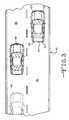
- FIG. 3a schematic plan view of a vehicle in which the turn signal assembly is installed and the surrounding roadway illustrating a proximity system for use with the turn signal assembly.
- the turn signal assembly 10includes a handle or stalk 12 mounted for pivotal movement on a steering wheel column 14 or a steering wheel 16 .
- the stalk 12is generally elongated and extends outwardly from the steering wheel column 14 .
- the stalk 12is pivotally mounted on the steering wheel column at a first end 12 a which is connected to a switch 17 .
- a free or second end 12 b of the stalkextends outwardly such that the end 12 b can be easily accessed by the driver of the vehicle in which the turn signal assembly 10 is mounted.
- stalk 12 and the switch 17are shown and described as being mounted on the column 14 , it should be understood that the stalk 12 and/or switch 17 could be mounted at any suitable location within the vehicle which is within reach of the driver, such as for example, on an instrument panel.
- Other vehicle accessory controlssuch as cruise control, high and low beam driving lights, parking lights, hazard lights or other controls, can be mounted on the stalk 12 .
- the stalk 10 and switch 17are designed to generally actuate a turn signal system incorporated into the assembly 10 .
- the turn signal systemis generally actuated by the movement of the stalk and provides a means for informing drivers of other vehicles on a roadway of the driver's intention to turn the vehicle or change lanes.
- the stalk 12is movable between a neutral or intermediate position, as shown in solid lines in FIG. 1, to a first or upward position, indicated by broken lines 20 in FIG. 1 .
- the stalk 12is also movable between the intermediate position and a second or downward position, indicated by broken lines 22 . Movement of the stalk 10 causes actuation of the switch 17 . When in the intermediate position, the turn signal system is not activated.
- the turn signal systemWhen in either of the first or second positions 20 and 22 , the turn signal system is activated, as discussed in detail below, to indicate the driver's intention of turning the vehicle.
- the upward position 20is representative of a right turn
- the downward position 22is representative of a left turn.
- the range of motion of the stalk 12is in a generally vertical plane.
- the switch 17 and turn signal systemare actuated for a right or left turn respectively.
- Most vehiclesalso include a pair of indicator lights 24 and 25 on a main control display 26 of a vehicle to indicate to the driver that the turn signal system has been actuated to indicate either a right or left turn.
- the assembly 10further includes a controller 28 , such as a microprocessor.
- the controller 28can be mounted in any suitable location within the vehicle.
- the indicator lights 24 and 25are connected to the switch 17 and/or controller 28 and are actuated to an “on” position to emit a light thereby alerting the driver that the turn signal system is activated.
- the vehiclealso includes exterior lights 29 and 30 (FIG. 3) mounted on the front and rear of the vehicle to indicate activation of the turn signal system to persons outside of the vehicle, such as other drivers of other vehicles.
- the exterior lights 29 and 30can be connected and controlled by the switch 17 and/or the controller 29 .
- the stalk 12is moved down into the downward position 22 .
- the turn signal systemwill indicate a left turn by activating the indicator lights 24 and 29 .
- the stalk 12can be moved up into its upward position 20 to activate the indicator lights 25 and 30 .
- the stalk 12may be temporarily locked into the respective position.
- the stalk 12can be moved from either locked position by the driver manually applying a slight force in the opposite direction to which the stalk 10 was moved.
- the stalk 12can be automatically unlocked and returned to the intermediate position if the steering wheel 16 is moved beyond a given point. For example, if the stalk 12 is moved into the position 20 to indicate a right turn, the stalk 12 will automatically return to the neutral position when the steering wheel is turned clockwise through a deactivation angle. This allows the driver to activate the turn signal system, turn the vehicle and continue driving without having to manually de-activate the turn signal system.
- the turn signaloperates similarly for a left turn.
- the stalk 12can also be moved into transitional positions between the intermediate position and the upward and downward positions 20 and 22 .
- the turn signal systemwill activate (either left or right).
- the stalk 12will not be in a locked position. Therefore, when the driver manually releases the stalk 12 , the stalk 12 will return to the intermediate position and the turn signal system will de-activate.
- Such movement of the stalk 12is typical when the driver wishes to indicate a lane change or make a smaller turn that will not cause the steering wheel to move through the deactivation angle.
- the turn signal assembly 10is preferably connected to a proximity sensor system for detecting the proximity of a second vehicle in proximity to the vehicle in which the turn signal assembly is mounted. As will be described below, one or more sensors 30 are used for determining the presence of a second vehicle. The sensor 30 is connected to the controller 28 .
- a roadway indicated generally at 40is illustrated with a main vehicle 42 installed with the turn signal assembly 10 of the present invention.
- a second vehicle 44is also traveling thereon.
- the main vehicle 42can change lanes by moving from a first, driving lane 46 to a second, target lane 48 .
- the driverwhen a driver activates a turn signal by means of the turn signal assembly 10 to indicate a lane change, the driver also verifies that a target area in the target lane 48 directly to the side and/or rear of the main vehicle 42 is clear of other traffic.
- This target areais generally defined as the continuously moving space about the periphery of the main vehicle 42 into which the main vehicle 42 would move upon completing a lane change.
- the target areais often in the blind spot of the driver.
- the blind spotis generally defined as the region to the sides and/or rear of the vehicle in which the driver may not be able to view the proximate vehicle in the rear and side view mirrors.
- the target areacan be any size such as the same general size of the main vehicle 42 or preferably even larger extending rearwardly.
- the target lane 48is the lane into which the main vehicle 42 intends to move. The amount of area within the target lane 48 that is detected by the sensor 30 varies with the number, position and actuation of the sensors on the vehicle 42 .
- the turn signal assembly 10convey information indicating to the driver when a second vehicle 44 is occupying the target area.
- the vehicle 42can include various sensors 30 mounted on the vehicle 42 to detect the presence of another vehicle 44 or other obstructions in the target lane 48 .
- the sensors 30can include one or more sensors to detect an obstruction in the “blind spot” of a driver, and the front, rear and/or side of the vehicle 42 .
- the sensors 30are able to determine whether the object detected is a vehicle.
- the lane change sensorscould detect when the vehicle 42 moves outside of certain roadway markings.
- the sensorsare adapted to sense conditions that are predictive of a vehicle 44 approaching or in the target area.
- the sensorsare proximity sensors which are adapted to sense the position and/or movement of a second vehicle 44 relative to the main vehicle 42 .
- the sensed movementmay be used to determine the velocity and/or acceleration of the second vehicle 44 relative to the first vehicle 42 .
- the sensorsare adapted to sense position and movement of a plurality of vehicles in the vicinity of the main vehicle 42 .
- the sensorscan be any suitable proximity sensor for detecting the presence of the vehicle 44 .
- the sensorsmay include a transceiver for transmitting electromagnetic waves and receive feedback from the waves to sense surrounding vehicles. Suitable waves include microwaves, infrared waves, ultrasound waves, radio waves, electromagnetic waves, laser beams, and others.
- the controller 28is adapted to receive the signals generated by the sensors 30 .
- the controller 28can perform the predictive function in any suitable manner.
- the controller 28uses an algorithm which is adapted to predict the position of the second vehicle 44 based on the sensed conditions, such as the sensed position and movement of the second vehicle 44 .
- the controller 28generates first and second signals representative of the predicted motion of the second vehicle 44 .
- the controller 30Upon detection by one or more of the sensors 30 that a second vehicle 44 is either in the target lane 48 or the target area, the controller 30 will actuate a tactile feedback mechanism, indicated generally at 34 , mounted on the stalk 12 to alert the driver to the presence of the second vehicle 24 in the target lane 48 .
- a tactile feedback mechanismindicated generally at 34
- the controller 28actuates the sensors 30 to detect the area surrounding the vehicle 42 .
- the tactile turn signal feedback mechanism 34operates to initiate the sensors to provide feedback any time the turn stalk 10 is moved out of the intermediate position. It is also preferred that the mechanism 34 operates in the transitional positions as that is when the stalk 12 must be held in position by the driver to actuate the turn signal.
- a tactile feedback mechanism 34would be more effective. If the sensors 30 and the controller 28 do not detect a vehicle 44 in the target area, as described above, then the mechanism 34 may not be actuated. However, if a vehicle 44 is detected when the driver actuates the turn stalk 12 , then the turn signal system communicates the presence of the vehicle 44 in the driver's blind spot or in the target area by actuating the tactile feedback mechanism 34 by the controller 28 .
- the tactile feedbackis supplied by a vibrating mechanism, indicated generally at 50 in FIG. 2 .
- the vibrating mechanism 50is preferably mounted in a hollow portion of the stalk 12 and can be any suitable component which causes a vibration of the stalk 12 .
- the mechanism 50may include an electric motor 52 connected to the controller 28 and actuatable by the controller 28 upon a signal therefrom.
- the motor 52rotatably drives a shaft 54 about a rotational axis A.
- a plate 56is connected to the end of the shaft 54 and is generally perpendicular to the axis A.
- a cam or weight 58is connected to the plate.
- the weight 58is mounted relative to the shaft 54 such that the center of gravity of the weight 58 is off-center from the axis A.
- the off-center mounting arrangementcauses a vibration of the mechanism 50 . Since the mechanism 50 is mounted on the stalk 12 , the stalk 12 will also vibrate.
- a tactile feedback mechanism 34can relay information indicative of the condition of the proximity of the second vehicle 44 , instead of merely being actuatable to an “on” and “off” position.
- the tactile feedback mechanism 34is preferably controllable to alter the tactile response dependent on the signal from the vehicle proximity sensor system corresponding to a condition of the proximity of the second 44 vehicle relative to the main vehicle 42 .
- Conditions of proximitymay include the closeness of the second vehicle relative to the main vehicle 42 , and/or the speed of the second vehicle 44 relative to the main vehicle 42 or any combination thereof.
- the tactile feedback mechanism 34is the vibrating mechanism 50
- the rotational speed of the shaft 54 via the motor 52could be increased or decreased to alter the frequency and/or the amplitude of the vibration.
- the amplitude of the vibrationcould also be controlled by altering the position of the weight 58 relative to the axis A, such as by a spring effected by the centrifugal force of the rotating weight 58 .
- the intensity and strength of the vibrationincreases as the vehicle 44 is closer to the main vehicle 42 .
- the driverreceives additional information regarding the severity of the situation compared to merely being informed of the presence of the second vehicle 44 detected by the sensor 30 .
- the stalk 12can be actuated if a distant second vehicle 44 is in the target lane 48 and is approaching the first vehicle 44 at a relatively high rate of speed relative to the main vehicle 42 .
- the intensity and intermittence of the tactile feedbackcommunicates the relative velocity of an approaching vehicle. It is preferred that the frequency and/or the amplitude of the vibrations of the stalk 12 be varied according to the potential danger of a vehicle in or approaching the target area in the target lane 48 .
- the controller 48would trigger the most active response of the stalk 12 . Also, a vehicle that is not in the target area, but is in the target lane 48 that is approaching at a high rate of speed would trigger an active response. Oppositely, a vehicle 44 that is in the target lane 48 , but is a safe distance away or is moving at a slower or equal speed, could trigger a mild or no response.
- the tactile feedback mechanism 34has been described as being a vibrating stalk 10 , it should be understood that any other form of tactile response can be used.
- the stalk 10can increase in temperature, rotate, or change the outer texture of the stalk 12 to provide tactile feedback.
- the tactile responsecould be raised ridges or bumps on the surface of the stalk 12 .
- the stalk 12vibrates laterally. However, the vibration could be in any direction. Additionally, the vibration could cause the stalk 12 to move in an axial direction along the length of the stalk 12 .
- One of the advantages of the present inventionis that the additional safety supplied by alerting the driver to another vehicle being in the target area or when turning while using the turning stalk 12 might encourage more people to use turn signals while driving.
Landscapes
- Engineering & Computer Science (AREA)
- Human Computer Interaction (AREA)
- Mechanical Engineering (AREA)
- Lighting Device Outwards From Vehicle And Optical Signal (AREA)
Abstract
Description
Claims (17)
Priority Applications (1)
| Application Number | Priority Date | Filing Date | Title |
|---|---|---|---|
| US10/394,372US6812833B2 (en) | 2002-04-12 | 2003-03-21 | Turn signal assembly with tactile feedback |
Applications Claiming Priority (2)
| Application Number | Priority Date | Filing Date | Title |
|---|---|---|---|
| US37257002P | 2002-04-12 | 2002-04-12 | |
| US10/394,372US6812833B2 (en) | 2002-04-12 | 2003-03-21 | Turn signal assembly with tactile feedback |
Publications (2)
| Publication Number | Publication Date |
|---|---|
| US20040090318A1 US20040090318A1 (en) | 2004-05-13 |
| US6812833B2true US6812833B2 (en) | 2004-11-02 |
Family
ID=32233185
Family Applications (1)
| Application Number | Title | Priority Date | Filing Date |
|---|---|---|---|
| US10/394,372Expired - Fee RelatedUS6812833B2 (en) | 2002-04-12 | 2003-03-21 | Turn signal assembly with tactile feedback |
Country Status (1)
| Country | Link |
|---|---|
| US (1) | US6812833B2 (en) |
Cited By (23)
| Publication number | Priority date | Publication date | Assignee | Title |
|---|---|---|---|---|
| US20040206292A1 (en)* | 2002-09-23 | 2004-10-21 | Kim Seong Woong | Vehicle safety system |
| US20050017858A1 (en)* | 2003-03-25 | 2005-01-27 | William Gross | Collision warning systems and methods |
| US20050062591A1 (en)* | 2003-09-05 | 2005-03-24 | Ervin Cheryl P. | Rear turning signal sensor |
| US20050208457A1 (en)* | 2004-01-05 | 2005-09-22 | Wolfgang Fink | Digital object recognition audio-assistant for the visually impaired |
| US20050258977A1 (en)* | 2004-05-18 | 2005-11-24 | Kiefer Raymond J | Collision avoidance system |
| US20060028322A1 (en)* | 2004-08-03 | 2006-02-09 | Clark Franklin D | Vibrating device for the turn signals in motorized vehicles |
| US20060155445A1 (en)* | 2005-01-07 | 2006-07-13 | Browne Alan L | Sensor based anticipatory lighting of controls |
| US20070109104A1 (en)* | 2005-11-16 | 2007-05-17 | Gm Global Technology Operations, Inc. | Active material based haptic alert system |
| US7408445B1 (en)* | 2005-02-23 | 2008-08-05 | Bill Cunningham | Proximity activated vehicle signaling system |
| US20080309515A1 (en)* | 2007-06-15 | 2008-12-18 | La Tendresse Ingo | Warning apparatus for a motor vehicle |
| EP2138351A1 (en) | 2008-06-24 | 2009-12-30 | Ford Global Technologies, LLC | Warning apparatus for a motor vehicle |
| US20110187498A1 (en)* | 2010-01-29 | 2011-08-04 | Immersion Corporation | System and Method of Haptically Communicating Vehicle Information From a Vehicle to a Keyless Entry Device |
| US20110309920A1 (en)* | 2010-06-21 | 2011-12-22 | Brooks James D | Tactile prompting system and method for tactually prompting an operator of a rail vehicle |
| US9308861B2 (en) | 2014-03-13 | 2016-04-12 | Bendix Commercial Vehicle Systems Llc | Vehicle dash switch module with haptic and visual indication |
| US9789896B2 (en) | 2014-07-09 | 2017-10-17 | Tampereen Yliopisto | Haptic device |
| DE102016206155A1 (en)* | 2016-04-13 | 2017-10-19 | Conti Temic Microelectronic Gmbh | Driver assistance system |
| US10691108B1 (en) | 2012-10-10 | 2020-06-23 | Steelcase Inc. | Height adjustable support surface and system for encouraging human movement and promoting wellness |
| US10827829B1 (en) | 2012-10-10 | 2020-11-10 | Steelcase Inc. | Height adjustable support surface and system for encouraging human movement and promoting wellness |
| US10869118B2 (en) | 2014-02-04 | 2020-12-15 | Steelcase Inc. | Sound management systems for improving workplace efficiency |
| US10863825B1 (en) | 2016-10-17 | 2020-12-15 | Steelcase Inc. | Ergonomic seating system, tilt-lock control and remote powering method and apparatus |
| US11124114B2 (en) | 2019-09-30 | 2021-09-21 | Ford Global Technologies, Llc | Blind spot detection and alert |
| US20240140471A1 (en)* | 2022-11-01 | 2024-05-02 | Honda Motor Co., Ltd. | Vehicle |
| US12376677B1 (en) | 2012-10-10 | 2025-08-05 | Steelcase Inc. | Ergonomic seating system, tilt-lock control and remote powering method and apparatus |
Families Citing this family (19)
| Publication number | Priority date | Publication date | Assignee | Title |
|---|---|---|---|---|
| JP4453514B2 (en)* | 2004-06-09 | 2010-04-21 | 日産自動車株式会社 | VEHICLE DRIVE OPERATION ASSISTANCE DEVICE AND VEHICLE HAVING VEHICLE DRIVE OPERATION ASSISTANCE DEVICE |
| DE102005014111A1 (en)* | 2005-03-22 | 2006-09-28 | Valeo Schalter Und Sensoren Gmbh | Switching device with a shift lever, in particular for a vehicle |
| US9754078B2 (en)* | 2007-06-21 | 2017-09-05 | Immersion Corporation | Haptic health feedback monitoring |
| US9727139B2 (en) | 2008-12-12 | 2017-08-08 | Immersion Corporation | Method and apparatus for providing a haptic monitoring system using multiple sensors |
| US20100152620A1 (en)* | 2008-12-12 | 2010-06-17 | Immersion Corporation | Method and Apparatus for Providing A Haptic Monitoring System Using Multiple Sensors |
| GB2478131A (en)* | 2010-02-25 | 2011-08-31 | Antonio Vacca | Indicator sensors and side lights |
| DE102012011709A1 (en)* | 2012-06-13 | 2013-12-19 | Valeo Schalter Und Sensoren Gmbh | Manually operable switching device for a vehicle with vibration device |
| DE102013210056A1 (en)* | 2013-05-29 | 2014-12-04 | Bayerische Motoren Werke Aktiengesellschaft | User interface for a vehicle and vehicle with such a user interface |
| JP6538657B2 (en) | 2013-06-11 | 2019-07-03 | イマージョン コーポレーションImmersion Corporation | System and method for pressure based haptic effects |
| TW201520107A (en)* | 2013-11-29 | 2015-06-01 | Hon Hai Prec Ind Co Ltd | Steer warning device and warning method |
| US10067566B2 (en)* | 2014-03-19 | 2018-09-04 | Immersion Corporation | Systems and methods for a shared haptic experience |
| US9393901B2 (en)* | 2014-07-21 | 2016-07-19 | Kostal Of America | Turn signal systems and methods |
| ITUB20153939A1 (en)* | 2015-09-28 | 2017-03-28 | Univ Degli Studi Di Parma | A SYSTEM AND ITS RELATED METHOD FOR DETECTION OF POLLUTING SUBSTANCES BY MEANS OF A REMOTE DRIVEN VEHICLE FROM AN OPTICAL CONTROL DEVICE |
| US9908370B2 (en)* | 2016-03-21 | 2018-03-06 | Faster Faster Inc. | Dual motor feedback system for electric motorcycles |
| DE102017002221A1 (en)* | 2017-03-08 | 2018-09-13 | Man Truck & Bus Ag | Technology for monitoring a blind spot area |
| JP6722722B2 (en)* | 2018-06-26 | 2020-07-15 | 本田技研工業株式会社 | Vehicle driving support system |
| CN110221702B (en)* | 2019-07-08 | 2024-01-02 | 延锋伟世通电子科技(上海)有限公司 | Vibration feedback device of touch panel |
| US11458891B1 (en)* | 2021-04-05 | 2022-10-04 | Toyota Research Institute, Inc. | Secondary horn system for a vehicle |
| KR20240009257A (en)* | 2022-07-13 | 2024-01-22 | 현대자동차주식회사 | Multi-function control unit and controlling method thereof |
Citations (16)
| Publication number | Priority date | Publication date | Assignee | Title |
|---|---|---|---|---|
| US5339075A (en) | 1992-11-24 | 1994-08-16 | Terrill Abst | Vehicular collision avoidance apparatus |
| US5463384A (en) | 1991-02-11 | 1995-10-31 | Auto-Sense, Ltd. | Collision avoidance system for vehicles |
| US5517196A (en) | 1992-08-14 | 1996-05-14 | Pakett; Allan G. | Smart blind spot sensor with object ranging |
| US5598164A (en) | 1992-08-10 | 1997-01-28 | Reppas; George S. | Vehicle obstacle avoidance system |
| US5734336A (en) | 1995-05-01 | 1998-03-31 | Collision Avoidance Systems, Inc. | Collision avoidance system |
| US5765116A (en) | 1993-08-28 | 1998-06-09 | Lucas Industries Public Limited Company | Driver assistance system for a vehicle |
| US5767793A (en) | 1995-04-21 | 1998-06-16 | Trw Inc. | Compact vehicle based rear and side obstacle detection system including multiple antennae |
| US5786772A (en) | 1996-03-22 | 1998-07-28 | Donnelly Corporation | Vehicle blind spot detection display system |
| US5790050A (en)* | 1996-06-25 | 1998-08-04 | Parker; Peter | Method and apparatus for a signal translator |
| US6091321A (en) | 1998-12-30 | 2000-07-18 | Karell; Manuel L | Method and apparatus of a vibratory indicator for use in vehicles |
| US6097285A (en) | 1999-03-26 | 2000-08-01 | Lucent Technologies Inc. | Automotive auditory feedback of changing conditions outside the vehicle cabin |
| US6211778B1 (en) | 1998-09-14 | 2001-04-03 | Michael J. Reeves | Vehicle safety sensor |
| US6232910B1 (en) | 1998-02-20 | 2001-05-15 | Amerigon, Inc. | High performance vehicle radar system |
| US6236306B1 (en)* | 1997-05-05 | 2001-05-22 | Lyndon L. Liebelt | Tactual annunciating device for notifying vehicle or machinery status or condition |
| US6268803B1 (en) | 1998-08-06 | 2001-07-31 | Altra Technologies Incorporated | System and method of avoiding collisions |
| US6744370B1 (en)* | 1998-05-18 | 2004-06-01 | Inseat Solutions, Llc | Vibro-tactile alert and massaging system having directionally oriented stimuli |
Family Cites Families (1)
| Publication number | Priority date | Publication date | Assignee | Title |
|---|---|---|---|---|
| US5734326A (en)* | 1994-11-28 | 1998-03-31 | The United States Of America As Represented By The Secretary Of The Army | Recognition tag for use in a system for identifying distant items |
- 2003
- 2003-03-21USUS10/394,372patent/US6812833B2/ennot_activeExpired - Fee Related
Patent Citations (18)
| Publication number | Priority date | Publication date | Assignee | Title |
|---|---|---|---|---|
| US5463384A (en) | 1991-02-11 | 1995-10-31 | Auto-Sense, Ltd. | Collision avoidance system for vehicles |
| US5598164A (en) | 1992-08-10 | 1997-01-28 | Reppas; George S. | Vehicle obstacle avoidance system |
| US5517196A (en) | 1992-08-14 | 1996-05-14 | Pakett; Allan G. | Smart blind spot sensor with object ranging |
| US5339075A (en) | 1992-11-24 | 1994-08-16 | Terrill Abst | Vehicular collision avoidance apparatus |
| US5765116A (en) | 1993-08-28 | 1998-06-09 | Lucas Industries Public Limited Company | Driver assistance system for a vehicle |
| US5940011A (en) | 1995-04-21 | 1999-08-17 | Trw Inc. | Compact vehicle based rear and side obstacle detection system including multiple antennae |
| US5767793A (en) | 1995-04-21 | 1998-06-16 | Trw Inc. | Compact vehicle based rear and side obstacle detection system including multiple antennae |
| US5734336A (en) | 1995-05-01 | 1998-03-31 | Collision Avoidance Systems, Inc. | Collision avoidance system |
| US5786772A (en) | 1996-03-22 | 1998-07-28 | Donnelly Corporation | Vehicle blind spot detection display system |
| US5929786A (en) | 1996-03-22 | 1999-07-27 | Donnelly Corporation | Vehicle blind spot detection display system |
| US5790050A (en)* | 1996-06-25 | 1998-08-04 | Parker; Peter | Method and apparatus for a signal translator |
| US6236306B1 (en)* | 1997-05-05 | 2001-05-22 | Lyndon L. Liebelt | Tactual annunciating device for notifying vehicle or machinery status or condition |
| US6232910B1 (en) | 1998-02-20 | 2001-05-15 | Amerigon, Inc. | High performance vehicle radar system |
| US6744370B1 (en)* | 1998-05-18 | 2004-06-01 | Inseat Solutions, Llc | Vibro-tactile alert and massaging system having directionally oriented stimuli |
| US6268803B1 (en) | 1998-08-06 | 2001-07-31 | Altra Technologies Incorporated | System and method of avoiding collisions |
| US6211778B1 (en) | 1998-09-14 | 2001-04-03 | Michael J. Reeves | Vehicle safety sensor |
| US6091321A (en) | 1998-12-30 | 2000-07-18 | Karell; Manuel L | Method and apparatus of a vibratory indicator for use in vehicles |
| US6097285A (en) | 1999-03-26 | 2000-08-01 | Lucent Technologies Inc. | Automotive auditory feedback of changing conditions outside the vehicle cabin |
Cited By (41)
| Publication number | Priority date | Publication date | Assignee | Title |
|---|---|---|---|---|
| US20070146125A1 (en)* | 2002-09-23 | 2007-06-28 | Kim Seong W | Vehicle safety system |
| US20040206292A1 (en)* | 2002-09-23 | 2004-10-21 | Kim Seong Woong | Vehicle safety system |
| US7145449B2 (en)* | 2002-09-23 | 2006-12-05 | Seong Woong Kim | Vehicle safety system |
| US20050017858A1 (en)* | 2003-03-25 | 2005-01-27 | William Gross | Collision warning systems and methods |
| US7009503B2 (en)* | 2003-03-25 | 2006-03-07 | Idealab | Collision warning systems and methods |
| US20050062591A1 (en)* | 2003-09-05 | 2005-03-24 | Ervin Cheryl P. | Rear turning signal sensor |
| US6967568B2 (en)* | 2003-09-05 | 2005-11-22 | Ervin Cheryl P | Rear turning signal sensor |
| US20050208457A1 (en)* | 2004-01-05 | 2005-09-22 | Wolfgang Fink | Digital object recognition audio-assistant for the visually impaired |
| US20050258977A1 (en)* | 2004-05-18 | 2005-11-24 | Kiefer Raymond J | Collision avoidance system |
| US7245231B2 (en)* | 2004-05-18 | 2007-07-17 | Gm Global Technology Operations, Inc. | Collision avoidance system |
| US7187274B2 (en)* | 2004-08-03 | 2007-03-06 | Franklin D Clark | Vibrating device for the turn signals in motorized vehicles |
| US20060028322A1 (en)* | 2004-08-03 | 2006-02-09 | Clark Franklin D | Vibrating device for the turn signals in motorized vehicles |
| US20060155445A1 (en)* | 2005-01-07 | 2006-07-13 | Browne Alan L | Sensor based anticipatory lighting of controls |
| US7831319B2 (en) | 2005-01-07 | 2010-11-09 | Gm Global Technology Operations, Inc. | Sensor based anticipatory lighting of controls |
| US7408445B1 (en)* | 2005-02-23 | 2008-08-05 | Bill Cunningham | Proximity activated vehicle signaling system |
| US20070109104A1 (en)* | 2005-11-16 | 2007-05-17 | Gm Global Technology Operations, Inc. | Active material based haptic alert system |
| US7714701B2 (en)* | 2005-11-16 | 2010-05-11 | Gm Global Technology Operations, Inc. | Active material based haptic alert system |
| US8022818B2 (en)* | 2007-06-15 | 2011-09-20 | Ford Global Technologies, Llc | Warning apparatus for a motor vehicle |
| US20080309515A1 (en)* | 2007-06-15 | 2008-12-18 | La Tendresse Ingo | Warning apparatus for a motor vehicle |
| DE102007027529B3 (en)* | 2007-06-15 | 2009-01-15 | Ford Global Technologies, LLC, Dearborn | Warning device for a motor vehicle |
| EP2138351A1 (en) | 2008-06-24 | 2009-12-30 | Ford Global Technologies, LLC | Warning apparatus for a motor vehicle |
| US20110187498A1 (en)* | 2010-01-29 | 2011-08-04 | Immersion Corporation | System and Method of Haptically Communicating Vehicle Information From a Vehicle to a Keyless Entry Device |
| US8493177B2 (en)* | 2010-01-29 | 2013-07-23 | Immersion Corporation | System and method of haptically communicating vehicle information from a vehicle to a keyless entry device |
| US9666040B2 (en) | 2010-01-29 | 2017-05-30 | Immersion Corporation | Keyless entry device for haptic communications |
| US9978227B2 (en) | 2010-01-29 | 2018-05-22 | Immersion Corporation | Keyless entry device for haptic communications |
| US10204495B2 (en) | 2010-01-29 | 2019-02-12 | Immersion Corporation | Keyless entry device for haptic communications |
| US20110309920A1 (en)* | 2010-06-21 | 2011-12-22 | Brooks James D | Tactile prompting system and method for tactually prompting an operator of a rail vehicle |
| US12376677B1 (en) | 2012-10-10 | 2025-08-05 | Steelcase Inc. | Ergonomic seating system, tilt-lock control and remote powering method and apparatus |
| US11918116B1 (en) | 2012-10-10 | 2024-03-05 | Steelcase Inc. | Height adjustable support surface and system for encouraging human movement and promoting wellness |
| US10866578B1 (en)* | 2012-10-10 | 2020-12-15 | Steelcase Inc. | Height adjustable support surface and system for encouraging human movement and promoting wellness |
| US10691108B1 (en) | 2012-10-10 | 2020-06-23 | Steelcase Inc. | Height adjustable support surface and system for encouraging human movement and promoting wellness |
| US10719064B1 (en)* | 2012-10-10 | 2020-07-21 | Steelcase Inc. | Height adjustable support surface and system for encouraging human movement and promoting wellness |
| US10802473B2 (en) | 2012-10-10 | 2020-10-13 | Steelcase Inc. | Height adjustable support surface and system for encouraging human movement and promoting wellness |
| US10827829B1 (en) | 2012-10-10 | 2020-11-10 | Steelcase Inc. | Height adjustable support surface and system for encouraging human movement and promoting wellness |
| US10869118B2 (en) | 2014-02-04 | 2020-12-15 | Steelcase Inc. | Sound management systems for improving workplace efficiency |
| US9308861B2 (en) | 2014-03-13 | 2016-04-12 | Bendix Commercial Vehicle Systems Llc | Vehicle dash switch module with haptic and visual indication |
| US9789896B2 (en) | 2014-07-09 | 2017-10-17 | Tampereen Yliopisto | Haptic device |
| DE102016206155A1 (en)* | 2016-04-13 | 2017-10-19 | Conti Temic Microelectronic Gmbh | Driver assistance system |
| US10863825B1 (en) | 2016-10-17 | 2020-12-15 | Steelcase Inc. | Ergonomic seating system, tilt-lock control and remote powering method and apparatus |
| US11124114B2 (en) | 2019-09-30 | 2021-09-21 | Ford Global Technologies, Llc | Blind spot detection and alert |
| US20240140471A1 (en)* | 2022-11-01 | 2024-05-02 | Honda Motor Co., Ltd. | Vehicle |
Also Published As
| Publication number | Publication date |
|---|---|
| US20040090318A1 (en) | 2004-05-13 |
Similar Documents
| Publication | Publication Date | Title |
|---|---|---|
| US6812833B2 (en) | Turn signal assembly with tactile feedback | |
| US5598164A (en) | Vehicle obstacle avoidance system | |
| US6590495B1 (en) | Automobile distance warning and alarm system | |
| US7830243B2 (en) | Dual mode vehicle blind spot system | |
| US7046128B2 (en) | Collision detection and warning system for automobiles | |
| EP1261957B1 (en) | Blind spot detector | |
| JP5322937B2 (en) | Device for detecting moving objects | |
| JP2008531388A (en) | Method and apparatus for avoiding collision when changing lane of vehicle | |
| KR20180058405A (en) | Vehicle and method for controlling thereof | |
| EP1181584A1 (en) | Vehicle blind spot mirror | |
| JP3608432B2 (en) | Obstacle monitoring device for vehicles | |
| WO2005092667A1 (en) | Alarm of vehicle | |
| US20090244741A1 (en) | System, apparatus and method for active mirrors with blind spot detection | |
| JP4535094B2 (en) | Obstacle detection device for vehicles | |
| JPH07110899A (en) | Obstacle detecting device for vehicle | |
| JP3478149B2 (en) | Obstacle display device for vehicles | |
| JP3800624B2 (en) | Sensor system for judging the surrounding environment of a car | |
| JP3446509B2 (en) | Obstacle warning device on the rear side of the vehicle | |
| JP2830576B2 (en) | Inter-vehicle distance detection and alarm device | |
| KR20070012887A (en) | Side view winning mirror module and control method for side rear warning | |
| RU2724044C1 (en) | Collision warning method | |
| JPH08184675A (en) | Inter-vehicle distance alarm device | |
| JP2001283389A (en) | Obstacle detection device for vehicle | |
| JPH05290299A (en) | On-vehicle obstacle detector | |
| JPH0458179A (en) | Obstacle detecting device |
Legal Events
| Date | Code | Title | Description |
|---|---|---|---|
| AS | Assignment | Owner name:LEAR CORPORATION, MICHIGAN Free format text:ASSIGNMENT OF ASSIGNORS INTEREST;ASSIGNORS:ROTHKOP, JARON;MAUE, H. WINSTON;REEL/FRAME:013899/0742;SIGNING DATES FROM 20030310 TO 20030317 | |
| AS | Assignment | Owner name:JPMORGAN CHASE BANK, N.A., AS GENERAL ADMINISTRATI Free format text:SECURITY AGREEMENT;ASSIGNOR:LEAR CORPORATION;REEL/FRAME:017858/0719 Effective date:20060425 | |
| AS | Assignment | Owner name:INTERNATIONAL AUTOMOTIVE COMPONENTS GROUP NORTH AM Free format text:ASSIGNMENT OF ASSIGNORS INTEREST;ASSIGNOR:LEAR CORPORATION;REEL/FRAME:019215/0727 Effective date:20070427 | |
| REMI | Maintenance fee reminder mailed | ||
| LAPS | Lapse for failure to pay maintenance fees | ||
| STCH | Information on status: patent discontinuation | Free format text:PATENT EXPIRED DUE TO NONPAYMENT OF MAINTENANCE FEES UNDER 37 CFR 1.362 | |
| FP | Expired due to failure to pay maintenance fee | Effective date:20081102 | |
| AS | Assignment | Owner name:LEAR CORPORATION, MICHIGAN Free format text:RELEASE BY SECURED PARTY;ASSIGNOR:JPMORGAN CHASE BANK, N.A.;REEL/FRAME:032722/0553 Effective date:20100830 | |
| AS | Assignment | Owner name:LEAR CORPORATION, MICHIGAN Free format text:RELEASE BY SECURED PARTY;ASSIGNOR:JPMORGAN CHASE BANK, N.A., AS AGENT;REEL/FRAME:037731/0918 Effective date:20160104 |