US6812824B1 - Method and apparatus combining a tracking system and a wireless communication system - Google Patents
Method and apparatus combining a tracking system and a wireless communication systemDownload PDFInfo
- Publication number
- US6812824B1 US6812824B1US09/517,606US51760600AUS6812824B1US 6812824 B1US6812824 B1US 6812824B1US 51760600 AUS51760600 AUS 51760600AUS 6812824 B1US6812824 B1US 6812824B1
- Authority
- US
- United States
- Prior art keywords
- signal
- tag
- radio frequency
- frequency
- frequency identification
- Prior art date
- Legal status (The legal status is an assumption and is not a legal conclusion. Google has not performed a legal analysis and makes no representation as to the accuracy of the status listed.)
- Expired - Lifetime
Links
Images


Classifications
- G—PHYSICS
- G06—COMPUTING OR CALCULATING; COUNTING
- G06Q—INFORMATION AND COMMUNICATION TECHNOLOGY [ICT] SPECIALLY ADAPTED FOR ADMINISTRATIVE, COMMERCIAL, FINANCIAL, MANAGERIAL OR SUPERVISORY PURPOSES; SYSTEMS OR METHODS SPECIALLY ADAPTED FOR ADMINISTRATIVE, COMMERCIAL, FINANCIAL, MANAGERIAL OR SUPERVISORY PURPOSES, NOT OTHERWISE PROVIDED FOR
- G06Q30/00—Commerce
- G06Q30/06—Buying, selling or leasing transactions
- G—PHYSICS
- G01—MEASURING; TESTING
- G01S—RADIO DIRECTION-FINDING; RADIO NAVIGATION; DETERMINING DISTANCE OR VELOCITY BY USE OF RADIO WAVES; LOCATING OR PRESENCE-DETECTING BY USE OF THE REFLECTION OR RERADIATION OF RADIO WAVES; ANALOGOUS ARRANGEMENTS USING OTHER WAVES
- G01S13/00—Systems using the reflection or reradiation of radio waves, e.g. radar systems; Analogous systems using reflection or reradiation of waves whose nature or wavelength is irrelevant or unspecified
- G01S13/02—Systems using reflection of radio waves, e.g. primary radar systems; Analogous systems
- G—PHYSICS
- G01—MEASURING; TESTING
- G01S—RADIO DIRECTION-FINDING; RADIO NAVIGATION; DETERMINING DISTANCE OR VELOCITY BY USE OF RADIO WAVES; LOCATING OR PRESENCE-DETECTING BY USE OF THE REFLECTION OR RERADIATION OF RADIO WAVES; ANALOGOUS ARRANGEMENTS USING OTHER WAVES
- G01S13/00—Systems using the reflection or reradiation of radio waves, e.g. radar systems; Analogous systems using reflection or reradiation of waves whose nature or wavelength is irrelevant or unspecified
- G01S13/74—Systems using reradiation of radio waves, e.g. secondary radar systems; Analogous systems
- G01S13/82—Systems using reradiation of radio waves, e.g. secondary radar systems; Analogous systems wherein continuous-type signals are transmitted
- G01S13/825—Systems using reradiation of radio waves, e.g. secondary radar systems; Analogous systems wherein continuous-type signals are transmitted with exchange of information between interrogator and responder
- G—PHYSICS
- G01—MEASURING; TESTING
- G01S—RADIO DIRECTION-FINDING; RADIO NAVIGATION; DETERMINING DISTANCE OR VELOCITY BY USE OF RADIO WAVES; LOCATING OR PRESENCE-DETECTING BY USE OF THE REFLECTION OR RERADIATION OF RADIO WAVES; ANALOGOUS ARRANGEMENTS USING OTHER WAVES
- G01S13/00—Systems using the reflection or reradiation of radio waves, e.g. radar systems; Analogous systems using reflection or reradiation of waves whose nature or wavelength is irrelevant or unspecified
- G01S13/74—Systems using reradiation of radio waves, e.g. secondary radar systems; Analogous systems
- G01S13/82—Systems using reradiation of radio waves, e.g. secondary radar systems; Analogous systems wherein continuous-type signals are transmitted
- G01S13/84—Systems using reradiation of radio waves, e.g. secondary radar systems; Analogous systems wherein continuous-type signals are transmitted for distance determination by phase measurement
- G—PHYSICS
- G01—MEASURING; TESTING
- G01S—RADIO DIRECTION-FINDING; RADIO NAVIGATION; DETERMINING DISTANCE OR VELOCITY BY USE OF RADIO WAVES; LOCATING OR PRESENCE-DETECTING BY USE OF THE REFLECTION OR RERADIATION OF RADIO WAVES; ANALOGOUS ARRANGEMENTS USING OTHER WAVES
- G01S13/00—Systems using the reflection or reradiation of radio waves, e.g. radar systems; Analogous systems using reflection or reradiation of waves whose nature or wavelength is irrelevant or unspecified
- G01S13/87—Combinations of radar systems, e.g. primary radar and secondary radar
- G01S13/878—Combination of several spaced transmitters or receivers of known location for determining the position of a transponder or a reflector
- G—PHYSICS
- G06—COMPUTING OR CALCULATING; COUNTING
- G06K—GRAPHICAL DATA READING; PRESENTATION OF DATA; RECORD CARRIERS; HANDLING RECORD CARRIERS
- G06K17/00—Methods or arrangements for effecting co-operative working between equipments covered by two or more of main groups G06K1/00 - G06K15/00, e.g. automatic card files incorporating conveying and reading operations
- G—PHYSICS
- G06—COMPUTING OR CALCULATING; COUNTING
- G06K—GRAPHICAL DATA READING; PRESENTATION OF DATA; RECORD CARRIERS; HANDLING RECORD CARRIERS
- G06K19/00—Record carriers for use with machines and with at least a part designed to carry digital markings
- G06K19/06—Record carriers for use with machines and with at least a part designed to carry digital markings characterised by the kind of the digital marking, e.g. shape, nature, code
- G06K19/067—Record carriers with conductive marks, printed circuits or semiconductor circuit elements, e.g. credit or identity cards also with resonating or responding marks without active components
- G06K19/07—Record carriers with conductive marks, printed circuits or semiconductor circuit elements, e.g. credit or identity cards also with resonating or responding marks without active components with integrated circuit chips
- G06K19/0723—Record carriers with conductive marks, printed circuits or semiconductor circuit elements, e.g. credit or identity cards also with resonating or responding marks without active components with integrated circuit chips the record carrier comprising an arrangement for non-contact communication, e.g. wireless communication circuits on transponder cards, non-contact smart cards or RFIDs
- G06K19/0724—Record carriers with conductive marks, printed circuits or semiconductor circuit elements, e.g. credit or identity cards also with resonating or responding marks without active components with integrated circuit chips the record carrier comprising an arrangement for non-contact communication, e.g. wireless communication circuits on transponder cards, non-contact smart cards or RFIDs the arrangement being a circuit for communicating at a plurality of frequencies, e.g. for managing time multiplexed communication over at least two antennas of different types
- G—PHYSICS
- G06—COMPUTING OR CALCULATING; COUNTING
- G06K—GRAPHICAL DATA READING; PRESENTATION OF DATA; RECORD CARRIERS; HANDLING RECORD CARRIERS
- G06K7/00—Methods or arrangements for sensing record carriers, e.g. for reading patterns
- G06K7/0008—General problems related to the reading of electronic memory record carriers, independent of its reading method, e.g. power transfer
- G—PHYSICS
- G06—COMPUTING OR CALCULATING; COUNTING
- G06K—GRAPHICAL DATA READING; PRESENTATION OF DATA; RECORD CARRIERS; HANDLING RECORD CARRIERS
- G06K7/00—Methods or arrangements for sensing record carriers, e.g. for reading patterns
- G06K7/10—Methods or arrangements for sensing record carriers, e.g. for reading patterns by electromagnetic radiation, e.g. optical sensing; by corpuscular radiation
- G06K7/10009—Methods or arrangements for sensing record carriers, e.g. for reading patterns by electromagnetic radiation, e.g. optical sensing; by corpuscular radiation sensing by radiation using wavelengths larger than 0.1 mm, e.g. radio-waves or microwaves
- G06K7/10019—Methods or arrangements for sensing record carriers, e.g. for reading patterns by electromagnetic radiation, e.g. optical sensing; by corpuscular radiation sensing by radiation using wavelengths larger than 0.1 mm, e.g. radio-waves or microwaves resolving collision on the communication channels between simultaneously or concurrently interrogated record carriers.
- G06K7/10029—Methods or arrangements for sensing record carriers, e.g. for reading patterns by electromagnetic radiation, e.g. optical sensing; by corpuscular radiation sensing by radiation using wavelengths larger than 0.1 mm, e.g. radio-waves or microwaves resolving collision on the communication channels between simultaneously or concurrently interrogated record carriers. the collision being resolved in the time domain, e.g. using binary tree search or RFID responses allocated to a random time slot
- G06K7/10059—Methods or arrangements for sensing record carriers, e.g. for reading patterns by electromagnetic radiation, e.g. optical sensing; by corpuscular radiation sensing by radiation using wavelengths larger than 0.1 mm, e.g. radio-waves or microwaves resolving collision on the communication channels between simultaneously or concurrently interrogated record carriers. the collision being resolved in the time domain, e.g. using binary tree search or RFID responses allocated to a random time slot transponder driven
- G—PHYSICS
- G06—COMPUTING OR CALCULATING; COUNTING
- G06K—GRAPHICAL DATA READING; PRESENTATION OF DATA; RECORD CARRIERS; HANDLING RECORD CARRIERS
- G06K7/00—Methods or arrangements for sensing record carriers, e.g. for reading patterns
- G06K7/10—Methods or arrangements for sensing record carriers, e.g. for reading patterns by electromagnetic radiation, e.g. optical sensing; by corpuscular radiation
- G06K7/10009—Methods or arrangements for sensing record carriers, e.g. for reading patterns by electromagnetic radiation, e.g. optical sensing; by corpuscular radiation sensing by radiation using wavelengths larger than 0.1 mm, e.g. radio-waves or microwaves
- G06K7/10316—Methods or arrangements for sensing record carriers, e.g. for reading patterns by electromagnetic radiation, e.g. optical sensing; by corpuscular radiation sensing by radiation using wavelengths larger than 0.1 mm, e.g. radio-waves or microwaves using at least one antenna particularly designed for interrogating the wireless record carriers
- G06K7/10356—Methods or arrangements for sensing record carriers, e.g. for reading patterns by electromagnetic radiation, e.g. optical sensing; by corpuscular radiation sensing by radiation using wavelengths larger than 0.1 mm, e.g. radio-waves or microwaves using at least one antenna particularly designed for interrogating the wireless record carriers using a plurality of antennas, e.g. configurations including means to resolve interference between the plurality of antennas
- G—PHYSICS
- G07—CHECKING-DEVICES
- G07C—TIME OR ATTENDANCE REGISTERS; REGISTERING OR INDICATING THE WORKING OF MACHINES; GENERATING RANDOM NUMBERS; VOTING OR LOTTERY APPARATUS; ARRANGEMENTS, SYSTEMS OR APPARATUS FOR CHECKING NOT PROVIDED FOR ELSEWHERE
- G07C9/00—Individual registration on entry or exit
- G07C9/20—Individual registration on entry or exit involving the use of a pass
- G07C9/28—Individual registration on entry or exit involving the use of a pass the pass enabling tracking or indicating presence
Definitions
- the inventionrelates to tracking systems and, more particularly, to systems designed to track articles and personnel.
- Global positioning systems and local positioning systemsare examples that may be used depending on the particular items or persons being located. Included as part of these systems are various embodiments of hardware and software. The hardware may be used, for example, to collect data about the various entities being tracked or located.
- Long range identification or tracking systemsare designed to read large numbers of tags every few seconds, wherever they may roam in a bounded environment.
- these tagsmay be e usually low-powered, for example, emitting in the range of 1-10 mW.
- read rangesup to about 100 meters can be realized.
- read rangesmore like 25 meters is typical.
- an antenna placed every 20 meters or sois often needed for reliable coverage of a complete indoor space. In such instances, installing an antenna every 20 meters can pose a substantial installation challenge. In some cases, cable installation costs can exceed hardware costs, and the installation process can cause significant business disruption. Therefore, it is desirable to find additional uses for the same antennas such as enabling one installation to be used for several purposes.
- the systemincludes a radio frequency identification tag, a wireless communication system, an antenna module, and a controller.
- the antenna moduelis used in transmitting and receiving signals from the radio frequency identification tag.
- the antenna moduleis also used in transmitting and receiving signals used in the wireless communication system.
- the controlleris coupled to the antenna module. The controller is used in communications with the radio frequency identification tag and the wireless communication system.
- a method for locating objects and operating a wireless communication systemis a method for locating objects and operating a wireless communication system. Signals are transmitted and received using an antenna module from the radio frequency identification tag and from the wireless communication system. A controller is coupled to the antenna module and used in communications with the radio frequency identification tag and the wireless communication system.
- FIG. 1shows an overview of a positioning system
- FIG. 2shows several cell controllers deployed in a multi-story building
- FIG. 3is a block diagram of a tag RF design
- FIG. 4is a block diagram of an alternative embodiment of a tag
- FIGS. 5A-5Gare diagrams of a signal as it passes through various stages of the system
- FIG. 6is a block diagram of the cell controller RF design
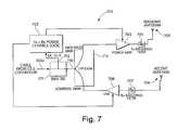
- FIG. 7is a block diagram of a cell controller active antenna module
- FIG. 8is a block diagram of a modulator RF design
- FIG. 9is a block diagram of a cell controller cable extender module
- FIG. 10is a block diagram of a cell controller
- FIG. 11illustrates extraction of tag data from a series of correlations
- FIGS. 12A-Care diagrams of tag datagrams
- FIG. 13shows a tag incorporating a delay element
- FIG. 14shows several cell controller receive chains operating in parallel
- FIG. 15Ais a block diagram of an embodiment of the signal processing hardware of FIG. 10;
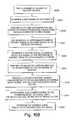
- FIG. 15Bis a flowchart depicting method steps of one embodiment of the Signal processing hard ware unit of FIG. 10;
- FIG. 16is a block diagram of an embodiment of a signal filtering technique
- FIG. 17is a block diagram of an embodiment of the transversal filter of FIG. 16;
- FIG. 18is a flowchart depicting method steps of one embodiment of the recursive-least squares (RLS) technique as used in a method step of FIG. 15B;
- RLSrecursive-least squares
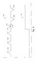
- FIGS. 19A-19Eare diagrams of sample waveforms in embodiments of the system of FIG. 1;
- FIG. 20is a flowchart depicting method steps of one embodiment of approximating a peak of the filtered tag signal
- FIG. 21is an example of an embodiment of a block diagram of a cell controller
- FIG. 22is an example of an embodiment of a block diagram of a cell controller active antenna radio frequency block diagram
- FIG. 24is an example of an embodiment of tag specifications
- FIG. 25is an example of another embodiment of a position system
- FIG. 26is an example of an architecture of a local positioning system (LPS) cell controller
- FIG. 27is an example of an embodiment of a “fixed” portion of a digital enhanced cordless telecommunications (DECT) installation
- FIG. 28is an example of an embodiment of a single base station supporting DECT and LPS systems
- FIG. 30is an example of another embodiment of a system including integration of LPS technology.
- the local positioning system described in paragraphs that followis an article tracking system that may be used, for example, to track and locate objects indoors.
- This systemmay be characterized as a radio-frequency identification system.
- a radio-frequency identification systemGenerally, such a system may also be used in a variety of other local positioning applications, such as outdoor tracking of objects or locating personnel indoors as well as outdoors.
- Limitations specific to the embodiments described hereinare not meant to imply limitations to the claimed invention.
- Radio Frequency Identification (RFID) productstypically have three components: (1) a tag (the item being identified), (2) an interrogator (a device which detects the presence of a tag), and (3) a system (typically including cabling, computers, and software which tie together the tags and interrogators into a useful solution). RFID products are typically designed to detect tags when they pass within range of a few fixed or handheld interrogators.
- Passive RFID tagshave been employed in conjunction with access control, smart cards, vehicle identification (AVI), waste management, item tracking, animal identification, manufacturing control, materials handling, and a variety of other purposes.
- Circuitry in the tagreceives a carrier from the interrogator, translates the signal to another frequency, and emits a response modulated onto that second frequency.
- the tagis charged by the interrogator. When the interrogator's charging circuit turns off, the tag uses the stored power to respond.
- the tagmodulates its antenna cross section to identify itself to the interrogator.
- SAWSurface acoustic wave
- Active RFID systemsrequire battery-powered tags.
- the batterypermits a longer detection range of between 3 and 100 meters.
- These systemsare capable of locating tags with higher accuracy than passive RFID systems and typically operate in the 400, 900, 2440, or 5800 megahertz bands.
- Active tagstend to enable multiple tags to be within range of an interrogator by the use of “handshaking” between the tags and interrogator, so that each tag transmits its signal in turn. Communication between tag and interrogator in active RFID systems is also typically faster than with passive tags.
- Some active RFID tagsrespond to the interrogator when polled, in accordance with a communications protocol. Some active RFID tags “chirp” (transmit) a signal spontaneously at predetermined intervals. A tag's chirped signal is detected by the interrogator if the tag is in range of the interrogator.
- Infrared systemsWhile not RFID systems, also endeavor to detect and identify the position of mobile tags.
- a typical IRID systemincludes a tag that chirps its identity at randomized intervals. Infrared readers located in the ceiling detect these transmissions, and report them to a host. The transmission rate from the tag to reader is typically about 600 baud. Motion detectors in the tags enable the tags to transmit more frequently when in motion. The tags are typically about the size of dominos.
- EAS systemsare intended to deter theft in retail environments.
- EAS tagsare fairly unreliable, very low in cost, and limited in capabilities. Although they track mobile tags, they are not generally considered to be identification products, because EAS tags are uncoded and cannot be distinguished from one another.
- an article tracking system 100contains the following general components:
- TagsInexpensive miniature radio frequency transponding tags 101 a-c are attached to people and/or items being tracked. Tags 101 a-c “wake up” periodically, and “chirp” (transmit) a radio-coded unique identity code (UID).
- the tags 101 a-care designed so that their range is 50-100 meters in a typical indoor environment, the range mostly being limited by a need to conserve the life of the tag battery, and the requirement that the tag 101 a and tag battery be small and thin.
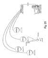
- Cell controllers 102 a-cdetect the chirps of tags 101 a-c and calculate the distances of those tags 101 a-c to active antenna modules 104 a-d connected to the cell controllers 102 a-c .
- Each antenna modulepreferably has a transmit antenna and a receive antenna.
- the antenna modules connected to cell controllers 102 b and 102 care omitted for simplicity.
- a cell controller 102 ais typically contained in a case and is mounted behind a hung ceiling. The cell controller 102 a can receive power from a conventional wall outlet or the equivalent.
- the cell controller 102 ais attached through coaxial cables 103 a-d to the antenna modules 104 a-d , respectively, which provide coverage of an area of the indoor facility 110 .
- a tag signal 107transmitted by a tag 101 a , is received by one or more antenna modules 104 a-d , and is processed by chips in the cell controller 102 a , such as digital signal processing (DSP) chips as may be included in the signal processing hardware.
- DSPdigital signal processing
- Cell controllers 102 a-care in data communication with a host computer 105 , which collects data and information available from the cell controllers 102 a-c and archives the data into an open format database, such as an SQL Server.
- a host computer 105which collects data and information available from the cell controllers 102 a-c and archives the data into an open format database, such as an SQL Server.
- client workstations 120 a-ccommunicate with the host computer 105 over a network, such as a LAN 115 .
- a client application running on each of the client workstations 120 a-ccan access the SQL Server and presents the data in a way that is useful to an end-user.
- the tag 101 adoes not generate its own radio signal. Rather, an antenna module, for example antenna module 104 a , continuously transmits a direct sequence spread spectrum interrogator signal 106 at a first frequency, for example 2440-megahertz. The tag 101 a receives this signal 106 , modulates its UID code onto the signal 106 , and immediately transmits back a frequency-shifted signal 107 at, for example, 5800-megahertz to, for example, antenna 104 a . The distance from the antenna module 104 a to the tag 101 a can then be determined by the cell controller 102 a from the round trip time of transmission, accounting for fixed and known delays in the wiring and electronics.
- an antenna modulefor example antenna module 104 a
- the tag 101 areceives this signal 106 , modulates its UID code onto the signal 106 , and immediately transmits back a frequency-
- the cell controller 102 acan quickly switch among antenna modules 104 a-d to obtain the distance from the tag 101 a to each of antenna modules 104 a-d (which receive the return signal 107 ), and from that information determines the tag's location by triangulation techniques.
- the system 100is designed to be scaleable, allowing addition of cell controllers to existing cell controllers 102 a-c and antenna modules to existing antennas modules 104 a-d to improve the precision with which tag location is determined.
- FIG. 2shows how a collection of cell controllers 102 a-c can be deployed in the large multistory building 110 .
- multiple cell controllers 102 a-cfeed data to a single host computer 105 , typically through a TCP/IP communications network.
- a variety of data protocols and transfer mechanismscan be used in preferred embodiments. For example, if a local area network is not available, connection to the host can be accomplished via RS485, RS232, RS422, power line modem, or a dedicated phone line. Alternatively, specialized modems designed for use on such cables can be employed.
- Each of the cell controllers 102 a-ccan be installed to cover a separate floor 130 a-c , respectively, with the exact configuration being modifiable by a system administrator.
- cell controller 102 aOn floor 130 a , cell controller 102 a , with its collection of antenna modules 104 a-d , is installed in the ceiling 140 a . The same configuration of equipment is used on the remaining floors 130 b-c .
- Antenna modules 104 a-dare designed to provide good gain downwardly and horizontally, and poor gain upwardly, so that a vertical location (that is, the floor) of a tag 101 a can be determined by noting which antenna modules 104 a-d receive the strongest signals from the tag 101 a .
- a ground planeis placed behind each antenna to reflect signals downward.
- the horizontal location of a tag 101 ais then roughly determined by noting which antenna modules 104 a-d receive a strong signal from the tag 101 a .
- the horizontal location of the tag 101 a with respect to an antenna module 104 acan be determined more precisely by estimating the distance from the tag 101 a to each antenna module 104 a-d , based on the combined time of flight of the interrogation signal 106 and the tag signal 107 .
- Each “cell,” consisting of a cell controller 102 a and its antenna modules 104 a-dcovers several thousand square feet of floor space. Each cell operates independently, enabling more cells to be added without affecting the performance of existing cells.
- inventionsmay include a wall mounted antenna radiating generally horizontally, rather than vertically.
- the selection of antenna typemay be based on a variety of functional factors familiar to one of ordinary skill in the art.
- a tag RF circuitry 300receives signal 106 at a tag receive antenna 301 and transmits tag signal 107 at a tag transmit antenna 312 .
- the function of the tag RF circuitry 300is to transpond the incoming spread spectrum signal 106 by frequency translation.
- the secondary function of the tag RF circuitry 300is to modulate tag data onto the emitted tag signal 107 , under the control of a microprocessor 308 .
- the information emitted on the tag signal 107includes, in a preferred embodiment of the invention, the serial number of the tag, datagram headers, and tag data 309 such as that derived from a motion indicator or a low power indicator.
- an Rx (receive) bandpass filter 302ensures that the tag is receiving signals only in the 2440 megahertz ISM band, rejecting radar signals, electronic newsgathering signals, and the like.
- the filter 302is implemented as an etched coupled stripline filter embedded in the circuit board.
- the signal 106is then amplified by an amplifier 303 to ensure that the received signal can be mixed, in a frequency mixer 304 , without degrading the signal to noise ratio (SNR).
- SNRsignal to noise ratio
- the frequency mixer 304translates or shifts the carrier frequency from 2440 megahertz to 5800 megahertz.
- the incoming signalwith a center frequency of 2440 megahertz, is mixed with the output of a phase locked oscillator (PLO) 305 with a center frequency of 3340 megahertz.
- PLOphase locked oscillator
- the PLO 305consists of a phase locked loop (PLL) chip with three inputs: (1) a sampled output from a voltage controlled oscillator (VCO); (2) a reference tone from a 10 megahertz oscillator; and (3) a frequency programming interface to a microprocessor 308 .
- VCOvoltage controlled oscillator
- the PLO 305outputs a 1670-megahertz tone, which is then doubled to give the desired 3340-megahertz result.
- the next element of the tag RF circuitry 300is a biphase modulator 307 which, under control of the microprocessor 308 , can either pass the 5800-megahertz signal unaltered, or change the phase of the signal by 180 degrees.
- the modulator 307is implemented as a single pole double throw RF switch 801 that feeds a 180 degree hybrid, as shown in FIG. 8 .
- Several forms of modulationcan be used, including on-off keyed (OOK) modulation, binary phase-shift keyed (BPSK) modulation, multiple phase-shift keyed (MPK) modulation, and quadrature amplified (QAM) modulation.
- BPSKis the preferred form of modulation.
- the output from the modulator 307is fed into an amplifier 310 , then is filtered by a transmitter bandpass filter 311 , and the output of filter 311 is emitted from a transmit antenna 312 as the tag signal 107 . Since the amplifier 310 operates at high frequency, it consumes significant power, and alternative embodiments (such as that shown in FIG. 4) that make this amplifier 310 unnecessary are preferred.
- the Tx Filter 311implemented as a 5-pole filter, is necessary to ensure tag compliance with FCC Part 15 requirements.
- the tag RF circuitry 300 shown in FIG. 3is intended to illustrate the general functions of a tag 101 a-c , with an embodiment that is workable and self-explanatory. Those skilled in the art will be able to combine multiple functions into single elements in order to conserve power and take full advantage of available parts, or implement the same functions with a custom ASIC.
- FIG. 4shows an alternative embodiment 400 which fulfills the same basic functions as that shown in FIG. 3, but with fewer components and using less power.
- the essential difference between the circuitry 400 shown in FIG. 4 and the circuitry 300 shown in FIG. 3is that the modulator 404 in FIG. 4 is placed before the frequency mixer 406 in order to reduce the number of components (for example, the amplifier 310 is eliminated) and to conserve power.
- a tagsuch as the tag 101 a
- a common crystal reference for both the PLO 407 and clock timing in the microprocessor 405is an important, if not critical, feature of the system, enabling the cell controllers 102 a-c to predict when a tag 101 a will transmit a tag signal 107 .
- Using the same crystal reference in the PLO 407 and in the microprocessor 405 clock timingallows the cell controller 102 a to accurately calibrate the source by measuring phase shifts in the received signal (as described hereinafter), and to synchronize its clock timing accordingly.
- transmit antenna 409 and receive antenna 401are combined into a single element, and which uses a diplexer with the single antenna structure.
- tags 101 a-care powered depending on the application. (Note that FIGS. 3 and 4 omit the tag power source.)
- a tag 101 awill be battery powered, with the RF stage turned on and off under control of the microprocessor 405 .
- the microprocessor 405goes into a low power state, where it merely waits until it is time to power up the tag 101 a again.
- all tag circuitry 400cycles on and off under analog control, using an RC time constant in the circuit 400 as the timing source.
- the tag 101 aUsing the tag RF circuitry 300 or 400 of FIG. 3 or 4 , if a tag 101 a is in range of two of the cell controllers 102 a-c , and those cell controllers are sending pseudonoise with low cross correlation characteristics, the tag 101 a will correctly transpond both signals simultaneously.
- Tags 101 a-crequire a period of time, on the order of a millisecond, to charge up and charge down. During these brief periods, typically, the tags 101 a-c will not be stable enough to use, but will nonetheless emit RF into the radio channel through the transmit antenna 409 . For high-performance applications, where radio bandwidth is limited, a microprocessor-controlled switch can be added to the tag's transmit chain to eliminate such spurious emissions.
- the tag RF circuitry 300 , 400 shown in FIGS. 3 and 4can be used in conjunction with different pairs of frequencies.
- the general approach described aboveworks for any two allowable FCC spread spectrum bands. For example, the following combinations are permissible for license-free radio under FCC regulation Part 15.247:
- Spread spectrum operationis not required; two licensed narrow bands can be used. However, spread spectrum operation in the 2440 and 5800 megahertz bands is assumed for the remainder of the discussion.
- the tag RF circuitry 300 , 400 shown in FIGS. 3 and 4use frequency division multiple access, i.e., the tag circuitry 300 , 400 receives and emits signals on different frequencies.
- An alternative embodiment 1500uses time division multiple access, as shown in FIG. 13 .
- the tag circuitry 1500 shown in FIG. 13takes as an input at a receive antenna 1501 a signal at one frequency, such as 915 mHz, and emits the same signal through a transmit antenna 1508 at the same frequency after a delay of a microsecond.
- a cell controllersuch as cell controller 102 a , transmits an interrogation signal 106 in bursts every 2 microseconds.
- a tagsuch as tag 101 a , takes this signal as an input through the receive antenna 1501 .
- the signalthen passes through elements 1502 - 1504 , as in FIGS. 3 and 4.
- a time delay element 1505is then used to delay for a microsecond.
- the signalthen passes through a transmit bandpass filter 1507 and is emitted from the transmit antenna.
- a SAW devicecan be used as the time delay element 1505 .
- the cell controllerceases transmission, and reflections of the interrogation signal 106 in the environment die down to a minimal level.
- This half-duplex approachallows single frequency operation, although with lower bandwidth than with a full-duplex frequency shifting approach.
- the delay-based tagis capable of modulating the response signal by a 180-degree phase shift.
- the tag design 1500 shown in FIG. 13is similar to those shown in FIGS. 3 and 4.
- FIG. 6shows the radio stage of a cell controller 102 a .
- the architecture of an antenna module, such as the antenna module 104is shown in FIG. 7 .
- the cell controller 102 a and its remote antenna modules 104 a-dmodulate a baseband square wave input onto a 2440-megahertz carrier, filter the resulting 2440 megahertz signal to comply with FCC transmission requirements, transmit that filtered 2440-megahertz signal through a selected antenna module, receive a returning 5800-megahertz tag response through the same antenna module, extract the I (Inphase) and Q (Quadrature) components of the demodulated baseband signal, and digitize the result for subsequent processing.
- the microprocessor 1001can change the behavior of the radio system by (a) modifying the baseband input signal 601 ; (b) modifying the chip rate, pseudonoise sequence length, and/or the pseudonoise sequence code; (c) modifying the transmit frequency 610 of radio transmitter 1002 and the receive frequency of radio receiver 1003 within a narrow range; (d) modifying the transmit gain of radio transmitter 1002 and the receive gain of radio receiver 1003 ; and (e) by switching antenna modules 104 a-d.
- the demodulated response 107 from the tag 102 ais split into I (Inphase) and Q (Quadrature) components by the receiver Radio 1003 , and digitized by a digitizer 636 .
- Signal processing hardware 1004for example a combination of DSP and FPGA components, reduces the output from the digitizer 636 , performing correlation operations at high speed. If binary phase-shift keyed (BPSK) modulation is used on the transmitting side, the I and Q channels are correlated separately and combined. For quadrature phase-shift keyed (QPSK) modulation, each channel must be correlated twice, once with each sequence.
- the correlated data from the signal processing hardware 1004is processed by a microprocessor 1001 , such as a Pentium processor. Communications between the microprocessor 1001 and the host computer 105 is accomplished using a TCP/IP protocol, with Ethernet being preferred.
- the data that is input to the transmit chainis a baseband input signal 601 which is a pseudonoise spreading sequence.
- the length of the sequence and the code encoded in the sequenceare set by a cell controller microprocessor 1001 , and can be varied depending on signal processing requirements. Thirty-one or 127 bit sequences are typical, giving about 15 dB and 20 dB of compression gain, respectively.
- the 2440 megahertz and 5780 megahertz bandscan support a 40 megahertz baseband input signal 601 , and the cell controller 102 a is designed to enable this full bandwidth to be utilized.
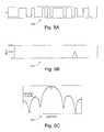
- FIGS. 5A-5Gshow an interrogation signal 106 as it passes through various stages of the cell controller RF circuitry 600 .
- FIG. 5Ashows a square wave baseband input to the modulator 500 .
- FIG. 5Bshows this baseband input digitally correlated 510 .
- FIG. 5Cshows an output 520 from a-modulator 602 , viewed through a spectrum analyzer centered at 2440 megahertz.
- FIG. 5Dshows a spectrum analyzer view 530 of the tag signal 107 , centered at 5780 megahertz.
- FIG. 5Eshows the demodulated response from tag 107 , separated into its I (Inphase) 545 and Q (Quadrature) 540 components.
- FIG. 5Fshows the I and Q components, digitally correlated 550 .
- FIG. 5Gshows the negative of the second derivative of the correlated waveform, combining the I and Q components 560 .
- the modulator 602(FIG. 6) modulates the baseband input 601 onto a 2440 megahertz carrier.
- Various forms of modulationare available and well-known to those skilled in the art.
- the modulator 602is implemented as a single pole double throw RF switch 801 that feeds a 180-degree hybrid combiner 803 , as shown in FIG. 8 .
- the modulator 602is preferably implemented as a QPSK modulator, which duplicates the BPSK modulator with one channel offset by 90 degrees from the other, each channel driven by a different baseband sequence with acceptable cross-correlation characteristics. Higher order modulation is also possible.
- Modulation by the modulator 602results in sidelobes extending for hundreds of megahertz, which need to be filtered to comply with FCC requirements.
- the 2440 megahertz bandhas an adjacent band, which imposes very strong filtering requirements, best addressed using in the illustrated embodiment using a SAW filter 607 that combines wide passbands with tight stopbands.
- a wider passbandsupports a faster chipping rate in the baseband input signal 601 , but a narrower passband provides an opportunity to use a wider range of frequency diversity to avoid jammers and/or support advanced signal processing techniques.
- the modulator 602must operate at the same frequency as the available IF filter 607 , typically in the range of 200 megahertz to 400 megahertz.
- a preamplifier 606is necessary prior to the SAW IF filter 607 , and the output of the filter needs to be amplified by an amplifier 608 .
- a transmit IF oscillator 605is phase locked to a 10 megahertz crystal source 603 , which is distributed through a filter and splitter network 604 to each of the oscillators.
- the 10 megahertz source 603needs to be within a few kilohertz of the 10 megahertz sources on the tags to avoid excessive baseband phase shift.
- the output from the IF filter 607(from amplifier 608 ) is then mixed by a mixer 609 with the output from a phase locked oscillator (PLO) 611 and is converted to a carrier frequency of 2440 megahertz.
- the frequency of the PLO 611can be modified within a narrow range under microprocessor control 610 , in order to provide the frequency diversity needed to avoid jammers and/or for various advanced signal processing techniques.
- the degree of frequency diversity availableis related to the specifications of the IF filter 607 , with narrower filters permitting a slower chip rate but having more frequency flexibility.
- a driver amplifier 612which raises the power level of the signal 106 , so that it can he driven down the cable 103 a to the remote antenna module 104 a , and which buffers the output of the mixer 609 for a bandpass filter 613 .
- the RF bandpass filter 613is needed to remove FCC non-compliant outputs from the mixer 609 .
- a directional coupler 616provides a port to examine the signal 106 before it is transmitted to the remote antenna modules, for example antenna modules 104 a-d.
- An attenuator 614 under microprocessor control 615allows the signal processing software to decrease output power when a tag 101 a-d is known to be nearby. This is helpful in circumstances when a nearby tag is known to be over-driven by the cell controller, and/or the signal processing software needs the tag to operate in a more linear range.
- the signalis then fed into a diplexer 618 , which combines the transmitted 106 and received 107 signals onto a single wire.
- the diplexer 618is a highpass/lowpass filter combination 619 a that attenuates a received signal 107 relative to the transmit side and attenuates the transmit signal 106 relative to the receive side. Because of the presence of the Tx and Rx bandpass filters 613 , 624 , the specifications of the diplexer 618 are not very stringent.
- the cell controller RF stage 600 shown in FIG. 6supports one remote antenna module 104 a-d at a time.
- the systemneeds a switch 619 , which enables a microprocessor control 620 to rapidly switch from one antenna to the next.
- the switch 619takes RF and passes it into one of n cables, where n is, for example either 8 or 16.
- the switch 619also provides DC power to the selected line.
- the RF signalis coupled into the cables with a capacitor (not shown), which provides DC isolation, and the DC power is coupled into the cables with RF chokes to provide RF isolation.
- the DC and RFtravel together through a single coaxial cable to the selected antenna.
- the rise time of the DC in an antennais in the range of 20 microseconds, limited by the effective resistance of the circuitry in and characteristics of the antenna and the capacitors needed for operation.
- the DC power to an antennais preloaded before the RF is switched.
- the combined DC and RF signalsarrive through a coaxial cable, such as the cable 103 a from the cell controller 102 a .
- a bias-tee 701separates the RF signal 710 from the DC signal 712 .
- the DC signal 712is sent to Tx/Rx power control logic 702 which, in the simplest embodiment is a filter to remove noise from the line and provide a clean 5 volt power source.
- the RF output 710 from the bias tee 701is fed into a diplexer 715 , which is identical to the diplexer 618 in the cell controller 102 a .
- Thisis then amplified by an amplifier 703 to the power level allowed by the FCC, and filtered by a filter 704 to remove line and amplifier noise in compliance with FCC regulations.
- the resulting signalis then sent to a transmit antenna 705 .
- the transmit antenna 705 and receive antenna 706are, in this embodiment, wall mounted patch arrays, providing reduced energy in the vertical direction and spreading energy laterally, so that power is not wasted in the floor and ceiling, and so that minimal power is radiated upward.
- the 5780-megahertz response 107 from the tag 101 ais filtered by a filter 707 , amplified by an amplifier 708 , and sent back down the cable 103 a to the cell controller 102 a.
- the systemis designed to use cables 103 a-d of a standard length, for example, 20 meters.
- a cable extender module 900connects two lengths of cable and supports an extended cable length. Referring to FIG. 9, the elements of the module 900 use the DC power 910 from the cable 103 to drive low noise amplifiers 903 , 904 , which provide enough gain to drive the next section of cable.
- Bias tees 906 , 907separate the DC power 910 from the RF signals, and diplexers 908 , 909 operate to separate the transmit signal 106 from the receive signal 107 .
- the signal returning from the antenna module 104 a to the cell controller 102 apasses through the switch elements 621 , 619 and diplexer 618 to the cell controller receive RF chain 622 .
- the signalpasses through a combination of a preamplifier 623 and bandpass filter 624 , the exact arrangement of which varies based on the parts selected.
- a digitally controlled receive attenuator 625 under microprocessor control 626is used to avoid saturating the receive chain when the tag 101 a is known to be nearby. This is necessary to avoid losing the relationship between the I and Q components of the received signal 107 , necessary for proper correlation and other signal processing.
- the signalthen enters an I-Q zero IF demodulator circuitry 627 - 633 .
- the microprocessor Rx frequency control 635must be set in tandem with its counterpart in the transmit chain.
- the resulting signalis fed into a digitizer 636 (FIG. 10) in preparation for digital signal processing.
- the embodiment described aboveis simplified, based on an assumption that the cell controller can send and receive from only one antenna at a given time. Improved performance can be achieved by selecting send and receive antennas independently of each other.
- Software in the cell controllerdetermines which antenna module receives the best signal from the tag. For example, if a particular tag, such as tag 101 a , is close to an antenna, such as antenna 104 a , then the antenna 104 will receive a strong signal from the tag 101 a .
- the cell controller 102 acan then transmit a signal, such as signal 106 , from antenna 104 a , and receive the transponded response 107 at antennas 104 b , 104 c , and 104 d in turn.
- the design 1600 shown in FIG. 14provides multiple receive chains 1610 a - 1610 n operating in parallel.
- Each of the receive chains 1610 a - 1610 nincludes an IQ demodulator, a digitizer, and a correlating element, shown as integer DSPs, for example, integer DSP 1620 .
- Implementing each receive chain on a separate cardprovides scaleability.
- the use of multiple receive antenna modules for the same transmitted signalallows the cell controller signal processing software to employ spatial processing techniques to isolate multipath effects. These techniques take advantage of the fact that the multipath-corrupted response will have different characteristics at each antenna.
- a simple triangular correlation peakcan be derived from a received tag signal 107 , as shown in FIG. 5 B.
- the essential pointis to reliably detect the existence of a series of correlations, which indicates the operation of a tag.
- FIG. 11shows how tag data is extracted from a series of correlations. In the left half of the chart 1110 shown in FIG. 11, the tag is transmitting a “one.” This is accomplished by setting the tag's modulator 307 to pass the interrogator signal 106 unaltered.
- Pseudonoise sequencescan be varied under microprocessor control at the cell controller when a tag's presence is first detected, relatively short sequences must be used, as shown in FIG. 11 . Once the tag's bit timing is ascertained, it is possible to use longer sequences for improved SNR, which is helpful in distance measurement.
- Each tagis a stand-alone unit that is unaware in any way of the outside world.
- Each taghas a Unique Identifying Code (UID) associated with the tag when it is manufactured.
- a tagwakes up periodically and, for a short period of time, converts any incoming 2440-megahertz signal 106 to an outgoing 5780-megahertz signal 107 , while modulating its UID and other data onto the outgoing signal 107 which it chirps (transmits).
- the tagdoes not communicate with other tags.
- the tagdoes not explicitly respond to an interrogation signal, but merely transponds any incoming signal 106 in the 2440-megahertz band, which may or may not include a pseudonoise sequence from a nearby cell controller antenna module 104 a . This approach greatly simplifies the design and fabrication of the tag 101 a.
- tags“wake up” and chirp their UIDs at randomized times, which can be calculated (by both the tag and the cell controller) based on a pseudorandom number generator which incorporates the tag's UID. For example, for a tag which chirps approximately every 5 seconds, the tag generates pseudorandom numbers between 0.0 and 2.0, and adds these to a 4.0-second minimum delay time, resulting in a sequence of delay times uniformly distributed between 4.0 and 6.0 seconds.
- a typical pseudorandom number generatorhas the form:
- the resulting Nis used as the seed for the next pseudorandom number in the pseudorandom number sequence.
- a pseudorandom number generator of this kindit is possible that two tags will use the same seed, resulting in their tag signals repetitively colliding. Further, with small differences in tag clocks, all pairs of tags will eventually drift through this synchronized state for some amount of time. To avoid these conditions it is desirable to incorporate each tag's UID, as noted above, into the delay time for that tag, resulting in a different pseudorandom sequence for each tag, that is:
- NXor(Delay, BitRotate(UID, And(N,1111 2 )).
- one embodiment of the tag datagram 1400contains a header 1401 to enable the cell controller to detect the tag's presence, followed by an identifier preamble 1402 , followed by the tag's UID 1403 .
- the header 1401can be of zero length.
- the identifier preamble 1402can be implemented, for example, as a validity check such as a cyclic redundancy check (CRC). Given a sufficiently simple Delay function and high clock stability, the cell controller can infer the tag's chirping sequence by noting the timing of a series of chirps of the datagram 1400 .
- CRCcyclic redundancy check
- the tagadds Delay information 1414 , thus enabling the cell controller to forecast the transmission time of the tag's next and subsequent chirps of the datagram 1410 .
- this informationwould include the data: Delay and And(N,1111 2 ).
- a shorter headeris used than in the datagrams 1400 , 1410 of FIGS. 12 a and 12 b , such that the cell controller is not guaranteed to have enough time to detect the tag's presence before the UID 1423 contained in the tag datagram 1420 is transmitted.
- Appended to the datagram 1420is the transmission delay 1425 of the next chirp, enabling the cell controller to anticipate the time that the tag will next chirp its datagram 1420 , even if the cell controller does not have enough time to identify the identity of the tag from the first received chirp of the datagram 1420 . The cell controller can then anticipate this next chirp and ascertain the identity of the tag at that time.
- the cell controllercan duplicate the tag's pseudorandom number generator to calculate the times of all future chirps by the tag.
- a series of special synchronization bits 1424are inserted between the UID 1423 and the delay information 1425 , to reliably determine when the UID 1423 ends; in this case, the UID 1423 must be defined so that it does not include the synchronization sequence or its inverse.
- FIGS. 12 a , 12 b , and 12 cinclude optional data sections 1404 , 1415 , 1426 , which allow a tag to transmit data to the cell controller.
- These sections 1404 , 1415 , 1426can include data from within the tag, such as from a motion detector or a low power indicator, or from an external device attached to the tag, such as metabolic information for medical telemetry if the tag is attached to a person.
- This identifier preambleenables the cell controller to quickly verify that a tag is chirping as expected, without needing to decode the tag's complete UID. This frees the cell controller for other activities, such as communicating with different tags in proximity to other antennas.
- the identifier preamble 1402 , 1412 , 1422 and tag UIDs 1403 , 1413 , 1423are set externally, and if appropriate can be defined to include error correction bits.
- the UID of a tagmay be hardcoded into the tag (e.g., as a serial number).
- Tagsmay be grouped based on their UIDs, and different groups may be associated with different cell controllers. Each cell controller contains information (received from another source) about which tags are in the group associated with the cell controller.
- the cell controllercan extract the UID information from the tag signal to determine whether the tag signal was sent by a tag in the group associated with the cell controller.
- the delay information fields 1414 , 1425 and data fields 1404 , 1415 , 1426can also include error correction bits.
- datacan be reduced to a stream of half-bytes.
- the tagcan look up the half-byte's value in a table which contains, for example, 8-bit values, which represent the value of the half-byte plus error correction information.
- a single cell controllercan handle all three types of datagrams 1400 , 1410 , 1420 shown in FIGS. 12 a-c . The choice of datagram type would depend on the application requirements for a particular tag.
- the amount of time it takes for a cell controller to detect the presence of a tagmay vary depending on the nature of the cell controller design. For example, a 100-microsecond time to switch antennas may be significant when the cell controller is cycling among 16 antennas.
- the tag datagram headerIn order to be assured that a tag will be identified the first time its tag signal is received by the cell controller, the tag datagram header must be long enough to give the cell controller time to try all of its antennas. If the performance requirement is in the range of 100 tags per second, 2 or 3 extra milliseconds in the header can be tolerated. But for higher performance requirements, or when tag power consumption must be minimized, it is necessary to either improve the performance of the cell controller or to use a tag datagram 1420 of the type shown in FIG. 2 c.
- the cell controllercan collect tag information from a variety of antennas in an organized way, in order to better calculate tag location by using antenna and/or frequency diversity. If a tag is responding exactly when it is expected to respond, it is not necessary for a cell controller to detect every bit transmitted in the tag datagram in order to be reasonably certain that it is receiving a signal from the correct tag. A correct identifier preamble arriving exactly on schedule is almost certain to be from the expected tag. This provides an opportunity for the cell controller to try a variety of antennas that may or may not be able to communicate with the tag.
- the tagcan be configured to send shorter transmissions more frequently. For example, if a tag is configured to chirp its datagram on average every 10 seconds, it may also be configured to transmit a much shorter code more frequently, such as every half-second. This shorter code might be as short as one bit long, and take just a few microseconds to transmit. Thus, even hundreds of such transmissions per second would consume only a small percentage of the communication channel.
- the cell controllercan anticipate the exact timing of each such transmission, thus matching each signal with the originating tag based on the time of the transmission. Error correction codes can be arranged such that long chirps from one tag will not typically be corrupted by quick chirps from other tags. The cell controller has the data to forecast most of such collisions.
- the cell controllerhas a means for sending information and instructions to the tag during the times that the tag is known by the cell controller to be in operation. Such instructions can include commands to be passed on to a device attached to the tag.
- the cell controlleris capable of downloading such information, most simply by on-off keying, or for more advanced tags by flipping the pseudonoise bit sequences to indicate one or zero.
- the downlink (downloading) approachis driven by tag cost and feature requirements, with higher bit downlink transmission rates requiring more expensive receivers that consume more power.
- a single cell controllercan support read-only tags, read/write tags, and high-speed read/write tags simultaneously, with the cell controller adapting its behavior depending on the features supported in a particular tag.
- Timing of transmission from tag to cell controllerdepends on the item being tagged. Inventory and equipment can be set to transmit relatively infrequently, such as once per minute. More frequent transmissions would be required, for example, for tags on people in a secure facility. For read/write versions of tags, timing of transmission could be modified on command from the cell controller.
- Alternative tag designsenable variation in transmission time based on environmental factors. For example, motion detectors may be placed in a tag to decrease the time between transmissions when the tag is in motion. As another example, a tag might transmit more frequently and with higher power when the tag has been tampered with. As another example, a tag might incorporate a slightly modified Electronic Article Surveillance (EAS) device, which would cause the tag to transmit its UID more frequently when in range of a standard EAS detector. More generally, if a tag is attached to another electronic device, transmission interval can be modified under the control of that device.
- EASElectronic Article Surveillance
- Tags 101 a-ctransmit a low RF power level in order to increase their portability and lifespan.
- tag signal transmissions 107are designed to be only a few milliseconds in duration. Therefore, even if a tag transponds its UID every few seconds, careful tag design allows the battery life of the tag to approximate the shelf life of the battery itself. For even lower power usage, a motion detector can be incorporated into the tag so that, for example, transmissions can be less frequent when the tag is stationary.
- battery replacementmay be accomplished by incorporating the battery in an attachment mechanism.
- re-usable tag electronicsmay be attached to a disposable patient bracelet, with the battery included in the bracelet.
- a batterymay be incorporated into the clip of an ID bracelet. More generally, a battery may be incorporated into an inexpensive disposable portion of an active RFID tag, with the electronics in the other, more expensive, portion.
- the tagcould tap into that power source. This approach is most practical in situations where the tag can he designed into the equipment itself (such as a handheld computer), or where the equipment and power source are large (such as a forklift). A larger power source allows for longer tag range.
- a tag signal 107is received at a time that is the sum of (1) known fixed delays in the cell controller 102 a that transmitted the interrogator signal 106 , due to its circuitry and the wiring to and from its antenna modules 104 a-d , (2) fixed time delays in the antenna module 104 a and tag 101 a , and (3) the time for the interrogator signal 106 and tag signal 107 to travel through the air.
- the travel time of the interrogator signal 106 and tag signal 107 through the airThe duration of the pseudonoise sequence modulated onto the 244 OMHz carrier signal 106 by the cell controller 102 a must be greater than the combined travel time of the signal 106 and the tag signal 107 .
- Techniques for correlating a pseudonoise sequenceare well known in the art. In the absence of multipath effects, the cell controller 102 a can derive a simple triangular correlation peak from the received tag signal 107 , as shown in FIG. 5 B. But in most indoor environments, the actual received tag signal looks more like that shown in FIGS. 5D-5G.
- a 40-megahertz chip rateresults in a correlation peak with a rise time of 25 nanoseconds, corresponding to a rise time distance of about 25 feet. Since tag location is calculated using round-trip travel time, single-chip accuracy therefore allows tag distance to be calculated within about 12 feet, without any advanced signal processing.
- Approximate location of a tagcan be calculated by noting when correlated signal-to-noise ratio rises above a predefined level. Improved accuracy can be achieved by trying a small variety of carrier frequencies and choosing the one that rises the earliest; such frequency diversity is supported by the radio system shown in FIGS. 4-6. This approach is sensitive to the system signal-to-noise ratio.
- MUSICrequires frequency diversity, which is supported by the radio system herein disclosed and shown in FIG. 6 .
- the methodis based on a decomposition of the eigenvector space of the pseudonoise correlation matrix of the delay profile data vector. Frequency diversity is required, where each distinct frequency provides the information to solve for an additional multipath component. For tags that are mostly stationary, necessary data can be collected and the calculation completed as a background process. For inventory applications, motion detectors can be incorporated into the tag, which would then inform the cell controllers whenever their locations need to be recalculated.
- Story-by-story discrimination in a buildingcan be accomplished by mounting antennas in the ceiling that radiate downward (or antennas in the floor that radiate upward), as shown in FIG. 2 .
- antennas mounted sideways on horizontal partitionscan determine location relative to those partitions.
- Relatively narrow beamwidth antennaswhich are less sensitive to multipath effects, can be directed at doorways and the like.
- a cell controller antenna 104 acan be mounted near a computer screen, with coverage corresponding to viewing angle of the screen. Software can then be arranged to automatically configure the operating system for the person in range, or to blank the screen for security purposes depending on who is or is not in range. Similar concepts can be used in conjunction with copying machines, microfilm readers, restricted equipment, and the like.
- a single antenna modulecan include three separate antennas placed in a triangle. By comparing phase difference using the Inphase and Quadrature components of the returning signal, an indication of the tag's angle can be determined. In high frequency embodiments, such as at 2.45 gigahertz, such antennas could be within inches of each other and be quite effective.
- Heuristic techniquescan be used to analyze the correlation profile to estimate the time at which the correlation began, that is, the time at which the correlation peak begins to be distinguishable from the “noise” baseline.
- Frequency diversitycan provide a variety of samples, the best of which can be chosen.
- Improved estimatescan be achieved by pattern matching the correlation peak with one of a vocabulary of well-studied typical correlation profiles.
- tagscan be placed at known fixed locations, and tags passing near those locations will likely demonstrate similar correlation profiles. Such fixed tags can also be utilized to detect the presence of jammers (objects which emit, intentionally or unintentionally, interfering signals) and to provide a real-time testbed for trying a variety of antijamming techniques.
- Antenna diversityis the most important tool for improving the accuracy of tag location calculation. If low accuracy is required, antennas can be placed so that only one antenna is in range of a given tag. In this case there is insufficient data for triangulation, and only enough information to detect tag presence and estimate tag distance from that antenna. Approximate bearing of a tag can be estimated from the signal strength of antennas designed for the purpose and well-known to those skilled in the art; with the caveat that such bearing tends to reflect the strongest signal received, which might include a substantial multipath component. Conversely, for areas requiring high accuracy, a diversity of relatively narrow beamwidth antennas can be installed, for example, at entrances, which together provide a clear picture of location.
- Antenna diversityalso provides system scaleability.
- substantially omnidirectional and/or ceiling mounted antennascan be installed relatively far from each other, for a relatively low cost per square foot of coverage.
- a diversity of closely-spaced and/or directional antennascan provide high accuracy at an increased cost.
- Tags dispersed at the entrance of a secure facilitycan be tracked through that facility and a special code can be emitted when the tag is tampered with.
- the tag's codecan be determined by monitoring the tag's response, the tag's transmission interval varies according to an algorithm that can be arranged to be known only to the tag and the host, and impossible to directly determine without destroying the tag.
- the tagmay for example, include an element, such as a physical element, for reprogramming its code and transmission interval. For example, a photo ID with an incorporated tag might be reprogrammed each time the person wearing the photo ID passes a security checkpoint, potentially in conjunction with biometrics technology.
- each cell controllerwill be operating according to a search and data collection method, rapid movement between antennas, the pseudonoise code, the changing chipping rate, and so forth, will appear as random noise to another cell controller.
- codes with known cross-correlation characteristicssuch as Gold Codes, can be allocated to various cell controllers by the host computer, particularly the codes used to search for tags.
- cell controllerscan switch choice of pseudonoise codes on a randomized basis.
- each cell controllerreports the tag's distances from its antenna modules.
- the central host 105assembles this data to calculate the tag's location.
- pseudonoise codesare available for use by a cell controller. Thus, if one code seems to be receiving interference from other users of the spectrum, the cell controller can choose another code.
- the tagbeing in essence a transponder, does not need to know the particular code being used. Likewise, center frequency can be adjusted somewhat if another user is causing difficulty.
- the signal processing hardware 1004performs operations upon the output of the digitizer 636 .
- the signal processing hardware 1004generally functions to perform operations upon the signal from digitizer 636 such as, for example, the previously described correlation. Additionally, signal processing hardware 1004 may perform a filtering process to filter out the noise components of received data signals. Various filtering techniques are known to those skilled in the art, such as the use of an adaptive transversal filter. Following is a description of functions that may be performed by the signal processing hardware 1004 in a preferred embodiment of the article tracking system of depicted in FIG. 1 .
- the signal processing hardwaremay include one or more hardware components that collectively perform digital signal processing of the received signals.
- the signal processing hardware 1004was previously described in connection with FIG. 10 .
- the processing set forth belowmay be implemented using any combination of conventional off-the-shelf hardware and/or software, utilizing DSP and/or FPGA hardware and/or semi-custom or custom ASICs, that may be configured by one of ordinary skill in the art using the description set forth herein.
- signal processing hardware 1004which is connected to the microprocessor 1001 and the digitizer 636 , as previously described in connection with FIG. 10 .
- a correlator unit 1800connected to other DSP hardware components 1800 .
- the number and type of components that are included in the other DSP hardware components 1802vary with the type of processing done in each particular implementation.
- Each of the hardware components included in the signal processing hardwaremay be controlled by the microprocessor 1001 , such as by using connections 1804 a and 1804 b .
- the connections requiredvary with each particular implementation and associated processing.
- signal processing hardware 1004uses only the correlator 1800 . In this instance, data is directly output by the correlation unit, as indicated by the path 1804 a . Generally, the other components 1802 and associated connections, such as 1804 b , would not be used in this embodiment. As will be described in paragraphs that follow in connection with FIG. 15B, only a portion of the method steps of FIG. 15B are performed by the signal processing hardware in this embodiment. In an alternate embodiment of the signal processing hardware which will also be described in paragraphs that follow, all of the method steps of FIG. 15B are performed as part of digital signal processing.
- a number of samples of received signalsare taken.
- the number of samples to be takenvaries with each particular implementation.
- the sampling rateis typically twice the transmission rate.
- 254 points or received signalsare sampled where each of the 254 signals is provided every 12.5 nanoseconds corresponding to the 80 megahertz sampling rate in which the system has a chipping rate of 40 megahertz.
- the signal transmitter rateis 127 chips per bit, or rather, every 3.2 microseconds a bit of data is transmitted.
- “chipping rate” and “chip time”are described in “The Practical Engineer”, IEEE Spectrum, Vol. 35, No. 9, September 1998.
- a first range of the sample received signalsis determined.
- the first rangeis a subset of the samples recorded, as in step 2000 .
- certain factors which are dependent upon each particular implementationmay be considered when determining the starting point and size of the first range of step 2002 .
- One factor that may be consideredis the anticipated arrival time of a signal returned by a tag. This relates to, for example, anticipated delays in the transmission circuitry and may be used in determining a starting point of the first range.
- Another factor that may be consideredrelates to the tag transmission range and the distance at which tags may be expected to be located. This may affect both the starting point of the first range as well as the size of the first range. For example, if objects in one system are known to be located within a small range, then the earliest possible time which a signal may be received by an antenna of a cell controller is earlier than a time of a different tag in another system in which objects are known to be located farther away from the transmission source. This may affect how many of the received signals which occur earlier in the sampling may be disregarded.
- the data collection event, the transmission of the signals, and the anticipated hardware delays and other timing delaysmay be calibrated in accordance with the starting point of the collection or sampling.
- approximately the 70 th samplewas determined to be the beginning of the first range because this was one of the earliest points at which a return signal may be expected in a particular embodiment.
- the actual span or size of the first rangeis 26 which was determined in accordance with the anticipated range of distances of objects to be located.
- step 2004auto-correlation is performed for the first range of samples producing a magnitude for each sample in the first range.
- the performing of auto-correlation upon received signalswas previously described.
- FIG. 5Bshows the results of performing auto-correlation upon the wave form 500 as shown in FIG. 5 A.
- the waveform 510 of FIG. 5Bdoes not include any “noise” in addition to the originally transmitted signal 500 as shown in FIG. 5 A.
- One preferred embodimentimplements the auto-correlation portion using a field programmable gate array (FPGA).
- FPGAfield programmable gate array
- the ability of the FPGA to perform massively parallel operations, such as matrix operations, efficiently in hardwareis one factor in considering using the FPGA to perform the auto-correlation function of step 2004 .
- use of particular hardware, such as the FPGAmay reduce the real time calculations and computational costs associated with performing expensive matrix operations, as in the method steps of FIG. 15 B.
- sample waveform254 consecutive samples of received data (“sample waveform”) are compared with an idealized version of the same data (“reference waveform”). If a coherent demodulation is available, then a real correlation may be performed. Otherwise, a complex correlation may be performed.
- Autocorrelationmay generally be defined as the integral:
- An autocorrelation functionis a plot of autocorrelation over all phase shifts (t ⁇ r) of the signal, where ⁇ t, the change in time, is in half-chirp intervals.
- each correlation calculationtakes 254 multiply-and-add operations, and calculating the entire autocorrelation function takes 254 2 which is approximately 64,000 multiply and add operations. If a complex reference waveform is used, computational complexity is increased by a factor of 4. Even with very fast hardware or specialized signal processing hardware, this number of calculations may cause a “bottleneck” due to the amount of time required to perform the calculations.
- a correlator implemented in hardwarecan generally make a quick estimate of tag location by combining various techniques, some as described above and other which will be described in the paragraphs that follow.
- the reference waveformgenerally includes 1's and ⁇ 1's
- 2's complement arithmeticmay be used for the multiplication operation.
- FPGAfield programmable array
- ASICapplication specific integrated circuit
- each interval of the autocorrelation functionIt is generally not necessary to calculate each interval of the autocorrelation function. Some of the range may be ignored because the tag is low-powered and can only be detected at a limited distance. For example, if the tag's radio has a maximum range of 100 meters, there is no reason to perform the autocorrelation function with phase shifts corresponding to the distances in excess of 100 meters. Additionally, in searching for the leading edge, phase shifts of a full chip or more may be used to search for the signal, and then half-chip intervals may be used in the neighborhood corresponding to the time when the first signal is detected. More generally, a subset of the 254 autocorrelation offsets may be used in the search for the peak or the rising edge of the autocorrelation function This is described in more detail in paragraphs below.
- step 2006heuristics are used to select a sample point which approximates where in the first range of received signals is the received tag signal. Generally, step 2006 produces a rough estimate as to the timing of the returned signal. This selected sample point is used, in connection with step 2008 , to further refine and limit the sampled data points considered in determining the returned signal.
- One heuristic or technique which may be used to approximate the location in the first range of the received tag signalis related to the strength or magnitude of the signals within the first range. By looking for the autocorrelation peak in the first subset, this corresponding signal may be used in approximating where the received tag signal may be located. Generally, this is based upon the premise that the strongest received signal corresponds to the direct path of the received tag signal.
- the rising or leading edge detection techniqueis a second heuristic that may be used to approximate where in the first range of receive signals is the actual receive tag signal. Generally, the samples are observed until a large or significant change in slope is detected. The actual determination of what is “large” or “significant” is relative to each system and varies with each implementation.
- One technique used with the rising or leading edge detectionmay include using a normalized value from 0.0 to 1.0 where 1.0 corresponds to the signal with the maximum amplitude received. When two points are encountered in which the slope of the line formed between these two points is greater than, for example, 20 percent of the normalized value, then this change may be considered large enough to signal a significant change in slope.
- the rising edge detection techniqueis based upon the assumption that the first peak is the line-of-sight returned signal. Note that this is different than the premise or assumption of the first technique which is based upon the assumption that the strongest returned signal is the returned tag signal.
- Yet another heuristicis a threshold detection technique.
- a threshold valueis determined, and the first sample point having a magnitude greater than or equal to this threshold is the selected sample point.
- the threshold value chosenvaries with environmental and implementation. Running trials of the system is one suggested method for choosing a threshold value.
- a second range of samplesis determined which is a subset of the first range of samples using the approximated location as determined in step 2006 .
- the precise starting and end point as well as the size or span of the rangemust be determined.
- Both the span of the second range as well as the precise starting and ending points of the second rangemay be related to or dependent upon the heuristic used to approximate the location of the received tag signal in step 2006 . For example, if the peak or maximum amplitude of the received signal were used in determining the approximate location of the receive tag signal, one common technique would be to take a specified number of equal points to the right and to the left of this peak and use this to correspond to the span and beginning and end points of the second range.
- a different techniquesuch as the leading or rising edge detection technique
- a varying number of points before and after the rising edgemay be used.
- One preferred embodimentmay use the rising edge detection technique or the threshold detection technique.
- a rangeis determined having a starting point which is three to the left of the rising edge, and eight points to the right of the rising edge.
- the second factor to be consideredis the actual size of the second range. It should be noted that the size of the second range in one particular embodiment is 12. The reasons and factors that may be considered when choosing the size of the second range will become more apparent in light of following paragraphs describing the different operations which are performed upon the second range of data.
- step 2010the recursive least squares (RLS) technique using the second range of samples is performed.
- the RLS techniqueis used in the design of adaptive transversal filters and is based upon the least-means square adaptation method, as generally known to those skilled in the art.
- the RLS technique used in step 2010is used to filter out the noise component of received signals.
- the RLS techniqueis used to filter out the noise components of the second range of sampled receive signals. The precise steps and how the RLS algorithm works are disclosed in the paragraph that follows.
- a vector of filtered samples corresponding to the second range of samples being filteredare produced. As previously described, this vector contains values which correspond to filtered received signals.
- the approximate peak corresponding to the filtered received tag signalis determined using the values included in the vector. Detail is described in the paragraphs that follow regarding how the peak is approximated using the values included in the vector produced by step 2012 .
- the tag distanceis determined using the time of the filtered received tag signal.
- the precise details of how to determine tag distance using the time of the filtered received tag signalwere previously described based upon the difference between transmission time and receipt time of the tag signal.
- One of the functions of the signal processing hardware 1004is to filter the noise component out of a received signal.
- FIG. 16shown is an example of an embodiment of a block diagram of a feedback control system which filters out noise components of received signals.
- the function of the block diagrams of FIG. 16combined filter out the noise components of a received signal.
- FIG. 16depicts a feedback control system which includes a transversal filter 2022 and an adaptive weight control mechanism 2024 .
- the transversal filter 2022operates upon an input signal u and represented as an input vector u(n) with a varying number of components.
- the transversal filterproduces an output signal E(n) which provides an estimate of the desired response d(n) 2028 .
- the desired response or signal d(n)is the actual received signal.
- the estimated signal E(n) produced by the filteris compared with the desired response signal 2028 to produce an error estimation ⁇ (n) 2030 .
- This estimation error ⁇ (n)is the difference between the desired response signal d(n) and the estimated signal E(n) 2026 as produced as an output by the transversal filter.
- This error value ⁇ (n) 2030is used as an input and feeds back into the adaptive weight control mechanism 2024 .
- the adaptive weight control mechanism 2024is a mechanism for performing the adaptive control process by varying certain parameters which feed back into the transversal filter 2022 .
- the transversal filter 2022may also be referred to as a tap delay line filter. Further description and details of the transversal filter is described in paragraphs that follow in connection with FIG. 17 .
- the RLS algorithmextends the use of the method of least squares to provide a recursive algorithm for the design of adaptive transversal filter such that, given the least squares estimate of the tap weight vector, w(n ⁇ 1) of the filter at time n ⁇ 1, the updated estimate of this vector at time n may be computed.
- the estimated signal E(n) 2026is denoted as w H (n ⁇ 1) u(n). The precise notation of this will be described also in paragraphs that follow.
- a transversal filterincludes three basic elements: unit delay elements ( 2031 a - 2031 m ), multipliers ( 2032 a - 2032 m ⁇ 1 ), and adders ( 2033 a - 2033 m ⁇ 1).
- unit delay operator 2031 aoperates on input u(n)
- the resulting outputis u(n) 1 .
- the role of the multiplier 2032 a in the filteris to multiply the tap input 2030 a by a filter coefficient referred to as a tap weight denoted w* 0 (n). It should be noted that the asterisk in FIG.
- the input signal u(n), and the tap weights denoted w(n)are represented as vectors with each element of the vectors corresponding to various components. When the various components are summed, they produce an estimated signal denoted y(i) in FIG. 17 .
- u(n)denotes the tap input vector at a particular time n.
- the tap weight vector w(n)defines the tap weight vector at a particular time n.
- the recursive least squares or RLS techniqueattempts to choose a tap vector w(n) which minimizes the expected squared error.
- the erroris determined as the sum of the differences between the expected or actual signal and the estimated signal output from the filter.
- the adaptive weight control mechanism 2024 of FIG. 17is used to determine the weighting factor associated with each of the errors at a particular point in time where the error is the difference between the desired response or the actual output signal, and the estimated signal produced by the filter.
- the use of the weighting factoris intended to ensure that data in the distant past is “forgotten” in order to afford the possibility of following the statistical variations of the observable data when the filter operates in a non-stationary environment.
- weighting factorallows additional weight to be given to the error values which are most recent in time, and give less weight to those error values which are earliest in time.
- the precise use of a weighting factor and how it relates to the measure of the “memory” of the RLS techniquewill become more apparent in following text.
- the adaptive weight control mechanism 2024provides a correction factor which is applied to the tap weights upon subsequent processing of data.
- a correction factor determined at time nis applied to the tap weight at a time of n+1.
- the error factorprovides for adjustment or correction of the various tap weights. This is the nature of the feed back mechanism of the system 2018 of FIG. 16 .
- FIGS. 16 and 17present a general description of the transversal filter and its corresponding adaptive control mechanism as generally known to those skilled in the art of adaptive filter theories as may be used in digital signal processing, for example.
- variablesare initialized to initial conditions. Generally, this includes variables used in subsequent method steps such as the loop control variable n. Some of the variables used in FIG. 18 processing steps are initialized to a set of initial conditions. Specifically, n is initialized to one in the method described in FIG. 18 .
- the tap weight vector w and the tap input vector umay be initialized to 0.
- the inverse of the correlation matrix denoted P( 0 )may be initialized to the inverse of a small positive constant time the identity matrix denoted 1 .
- the recommended choice of the small positive constant ⁇is that it should be small when compared to 0.01 times the variance of the data sample u(n).
- ⁇is a small positive constant which may be referred to as the “forgetting factor”. Since this constant is between zero and unity, multiplying a variable by ⁇ reduces the magnitude of the variable.
- ⁇is a small positive constant which may be referred to as the “forgetting factor”. Since this constant is between zero and unity, multiplying a variable by ⁇ reduces the magnitude of the variable.
- a weighted sum of square errorsis minimized by choosing a vector of coefficients. In this summation, the squared errors in the “past” are weighted by higher powers of ⁇ that are more “recent” squared errors.
- the coefficients produced by the RLS techniqueis generally chosen with less regard for errors in the past.
- ⁇should be set as close as possible to unity. In the instance of a time-varying system, ⁇ should generally be chosen such that: 1 1 - ⁇ > 3 * ( the ⁇ ⁇ number ⁇ ⁇ of ⁇ ⁇ coefficients ⁇ ⁇ estimated )
- the former conditiongenerally reflects the fact that the RLS technique provides a converged solution in 3 to 5 times the number of coefficients for cases in which the additive noise is not too severe.
- the latter conditionreflects the fact that the RLS technique attempts to find, for each sample input, a single vector of coefficients which may be used to approximate the last 1/1 ⁇ outputs of the time-varying system.
- controlproceeds to step 236 where a determination is made whether or not the loop control variable n is less than or equal to the number of desired iterations. If the determination is made that n is greater than the number of desired iterations, meaning that execution of the method steps of FIG. 18 is complete, control proceeds to step 238 where the method depicted in FIG. 18 stops. If a determination is made at step 2036 that n is less than or equal to the number of iterations, then control proceeds to step 2040 .
- ⁇ (n)is computed as:
- ⁇ ( n )d ( n ) ⁇ w H ( n ⁇ 1) u ( n )
- Step 2044the tap weight vector for a particular instance in time denoted w(n) is computed as:
- Controlthen proceeds to step 2048 where the loop control variable n is incremented by 1. Control proceeds to the top of the loop at step 2036 where a determination again is made whether or not the loop formed by steps 236 - 248 has been performed the desired number of iterations.
- the method step 2044describes the adaptive operation of this method whereby the tap weight vector w is updated by incrementing its old value by an amount equal to the complex conjugate (denoted by an *) of the a priori estimation error ⁇ (n) times the time varying gain vector k(n), hence the name “gain vector”.
- the a priori estimationdenoted ⁇ (n) represents the a priori estimation error.
- the a priori estimation errorrefers to an estimate of the error based on a tap weight vector that was made at time n ⁇ 1.
- the constant ⁇is a value close to 1. 1 ⁇ “represents a measure of the memory of the algorithm”.
- thisis a weighted value introduced in a definition of the cost function based on the error at time n.
- ⁇is a positive constant close to but less than 1.
- ⁇we have the ordinary method of least squares.
- the inverse of 1 minus ⁇is a measure of the memory of the algorithm.
- the special case where ⁇ equals 1corresponds to having infinite memory.
- ⁇is used in determining the actual weight given to particular values of the error determined at different points in time.
- this algorithmis deemed to be “recursive” for the fact that updating the tap weight vector at time n, a prior value for the tap weight vector at time n ⁇ 1 is used. This becomes apparent when method step 2044 is examined where the tap weight vector denoted w(n) is computed as being dependent upon the value w(n ⁇ 1). It should also be noted that in the flowchart of FIG. 18, the asterisk denotes the complex conjugate of a number. 10 Additionally, the superscript of H, as depicted in step 2042 when associated with the tap weight vector w, implies that the tap weight vector w has the Hermitian property. Generally, a complex valued matrix such as the tap weight vector w(n) is Hermitian if it is equal to its conjugate transpose, as known to those skilled in the art.
- step 2010performs the RLS technique just described using the second range of sample receive signals.
- the size or span of the second rangemay generally be related to use of the RLS technique.
- the RLS techniqueperforms matrix operations which are generally expensive in terms of computing time and resources. Thus, this expense is often a factor to be considered when determining the size of the second range in that the size of the second range affects the dimensions of the matrix and hence the number of matrix operations which are performed in computations of the RLS technique for the second range of samples. Additional factors should also be considered when choosing the size of the second range.
- the modelmay follow the peaks of the jammer signals rather than properly fit a curve identifying the filtered received signal. Additionally, if the size of the second range is too small, then enough points may not be considered to properly fit the curve. It should generally be noted that the number of points or data samples to be included in the second range varies with the system and implementation.
- the RLS technique used in this embodimentassumes that the observed sequence includes a linear combination of a known number of the data sequence. Generally, the RLS technique attempts to find the combining coefficients for this linear combination which best fits the observation. Generally, the RLS technique assumes a wide-sense stationary process. Generally, the RLS technique also presumes the presence of random additive noise which is uncorrelated with the data sequence. With the presence of “white noise”, the sum process remains generally wide-sense stationary. However, with the addition of a tonal frequency or jammer frequency, the sum process is no longer wide-sense stationary. To use the RLS technique when the sum process is not wide-sense stationary, such as may be in the application of this embodiment as used indoors, a corrective factor should generally be considered.
- the noise input to the correlatormay be modeled as the superimposition of two components: a wide-sense stationary white noise process, and a non-stationary intermittent plurality of tones of unknown frequencies and amplitudes. Based on this model for this particular embodiment, it is found that the number of coefficients or taps should generally span the main peak of the impulse response magnitude. However, the number of taps should generally not span more than this in this particular embodiment.
- the number of tapsmay vary with embodiment and application.
- the observed processshould be modeled to take into account all factors and a number of taps chosen in accordance with these considerations as described herein.
- factors that may be considered when choosing a size for the second rangeinclude consideration of the time complexity regarding computational expense as well as application for real time considerations when performing complex calculations. Additionally, the size of the second range varies with the environment in which this application will be used. If there will be tonal frequencies, such as a microwave oven within an indoor environment, this should be considered when choosing an appropriate value for the second range. In one preferred embodiment, a value of 12 was used for the size of the second range for an indoor article tracking system which included the previously described transmission rate of 127 bits per second in a sample of 254 points of received. This indoor system may possibly have tonal frequencies and other jammer signals since it is an indoor application as well as multipath noise. Thus, a range size of 12 for the second range was used considering these factors.
- the steps describing the RLS technique of FIG. 18may be performed using a different data sample set for each execution or iteration of the loop.
- one data set of 254 received signalswas recorded.
- the same data setis used for each iteration.
- the number of iterations of the RLS algorithmshould be as large as possible in order to meet the mathematical convergence for simulating when n goes to infinity.
- the method steps of FIG. 18, as described in the loop formed by steps 236 through 248are performed for 84 iterations. Through experimentation for this particular embodiment, it was determined that this was an optimal value to be used in the tradeoff of real time application, computational complexity, and accuracy of locating an object. For other systems and other applications, this number may vary.
- a vector of filtered samplesis produced in step 2012 .
- Each element in this vectorcorresponds to a component of a received signal which represents a filtered signal.
- each element of the vectorcorresponds to a filtered signal with the noise portion removed.
- the vector produced in step 2012is a vector of filtered signals in which each element of the vector corresponds to an element of the second range.
- the RLS technique performed in step 2010removes the noise component and returns a filltered signal.
- step 2014using the data points included in the vector of step 2012 , a technique is applied which approximates the peak corresponding to the filtered received tag signal.
- a techniqueis applied which approximates the peak corresponding to the filtered received tag signal.
- FIGS. 19A-19Eshown are sample waveforms of received signals for a number of sample points.
- FIG. 19Ashown is an example of a correlated received signal with a small amount of “white noise”.
- FIG. 19Bshows a waveform with a low degree of indoor multipath components as may be included in a received signal.
- FIG. 19Cillustrates a waveform that includes a medium degree of severity of indoor multipath noise in addition to a transmitted signal, and
- FIG. 19Dshows a severe amount of indoor multipath noise added to a transmitted signal.
- FIG. 19B-Dare waveforms that may be received in different environments within which a preferred embodiment of the invention operates.
- Shown in FIG. 19Eis a correlated waveform, labeled “correlation”, which is also typical as the output waveform after performing step 2004 of FIG. 15 .
- the second waveform, labeled “model” in FIG. 19Eis an example of a waveform resulting from graphing the 12 points included in the second range of samples which is output from the RLS technique in one preferred embodiment. As previously described, this vector may be produced in step 2012 after performing the RLS technique in step 2010 .
- the peak of the actual waveformfor example, may be approximated in step 2014 , as the 4 th data point of the “model” waveform of FIG. 19 E.
- the transmission rateis 127 chips per data bit.
- the bit pattern of the transmitted signalrepeats itself every 127 bits.
- a lesser number bit sequencesuch as 31 chips, may also be used in a particular implementation which requires less processing time and less number of samples to be taken.
- the gainis lost as you decrease the number of patterns in the bit sequence.
- a longer bit sequencegenerally allows for a greater distribution of energy over a larger period of time.
- a longer sequencegenerally enables a stronger signal at the output of the correlator than that produced by a shorter sequence.
- the processing gainindicates this signal strength enhancement and refers to the number of bits in the sequence.
- bit sequencewhich should be considered when implementing the techniques described herein relate to the properties of the bit sequence regarding auto-correlation and cross-correlation.
- a maximal sequencehas good auto-correlation but bad cross-correlation.
- a transmitted signal which is a maximal sequencewould produce an idealized peak waveform, for example as shown in FIG. 5 A.
- the cross-correlation of such a sequencemay not be desirable in an embodiment where better cross-correlation is required.
- good cross-correlationis often needed.
- a sequencesuch as the Gold code may also be used. It should be noted that the precise sequence length as well as the various properties of the sequence sent in the transmission signals may vary with application and each particular implementation.
- a local positioning systemwas described in which the assumption is made that the articles or persons being tracked by the system may be at a different position at any particular point in time. In other words, there is no assumption that the person or object will remain stationary for a majority of time.
- special processingmay be performed in the atypical case when an object is determined or sensed to have moved, as by a motion detector. When motion of a primarily stationary device has been detected, special processing may be performed using the techniques previously described.
- the systemmay devote additional processing time to locating the object.
- minimizing the amount of computational time to the extent as previously describedmay not be a factor in selecting, for example, the size or span of the second range.
- the signal processing hardware 1004may be implemented in varying combinations of software and/or hardware dependent upon the particular application and system implemented.
- the auto-correlation function performed in step 2004 on a first range of samplesis implemented in a FPGA, as previously described.
- other functions of the signal processing hardware 1004 as described hereinmay be implemented in varying combinations of software and/or hardware.
- the same data setwas used when performing multiple iterations of the RLS algorithm of FIG. 18 .
- a single data set setmay be “reused” on subsequent iterations with slight modifications, such as rotating or shifting to the right or to the left by one data element for each iteration.
- step 20shown are example steps of a method for approximating the peak corresponding to the filtered receive tag signal using the values included in the output signal vector produced as a result of step 2014 .
- the method steps shown in FIG. 20are more detailed steps of the method step previously described for step 2014 of FIG. 15 .
- For all of the magnitudes of the signals included in the output signal vectordetermine the largest magnitude, as in step 2100 . It should be noted that in one embodiment, if the first or last element of the vector has the largest magnitude, then an assumption is made that the received signal cannot reliably be determined, and the method stops execution.
- a threshold valueis determined which, in one embodiment is equal to 62.5 percent of this largest magnitude previously determined in step 2100 .
- step 2106other elements of the vector are selected to be used in subsequent processing steps to determine the actual received signal.
- two other elementsare generally chosen. These are the vector elements denoted by the indices “X+1” and “X+2”. It should be noted that the element indicated by the index value “X+2” is not used if the the “Xth” element is the second to last vector element.
- step 2108using a weighted average formula of these 3 points, the actual received tag signal is determined based on the expected shape of the received signal as being a correlated signal with a triangular peak.
- One embodimentcalculates or estimates the received tag signal as indicated in the pseudo-code type description below. It should be noted that the description below generally summarizes that which is set forth and previously described in conjunction with the method steps of FIG. 20 .
- step 2004the autocorrelation (step 2004 ) is performed by the correlator 1800 .
- the approximation produced as a result of using the heuristics at step 2006is considered to be the received tag signal.
- a first heurisitic, as used in step 2006determines the received tag signal to be the signal in the first range with the maximum magnitude of all the signals in the first range.
- a second or alternate heurisitic that may be included in an embodimentis to choose a threshold value.
- the first signal included in the first range having a magnitude equal to or exceeding this magnitudeis determined to be the received tag signal.
- the method for choosing the threshold valuemay vary with environmental and other factors particular to each implementation. Generally, this threshold value is selected in accordance with trial test runs of particular implementations to allow for “tuning” the threshold value. Using either heuristic, this received tag signal is then used (step 2016 ) in determining the tag distance.
- signal processing hardware 1004may include other hardware components in accordance with the particular digital signal processing requirements in a particular embodiment. Each particular embodiment may be implemented in using a variety of combinations of hardware components, including, but not limited to, gate arrays and read-only-memory. Additionally, other embodiments of the signal processing hardware may be implemented as some combination of hardware and software in which the machine executable code may be executed on a computer system, such as the microprocessor 1001 or the host computer 105 or yet another computer component included in the signal processing hardware 1004 as a dedicated processing unit. The components may vary with application and design choices associated with a particular implementation.
- Another embodiment of the signal processing hardwareincludes hardware and/or software in addition to the correlator. This embodiment may perform, for example, all the method steps of FIG. 15B, rather than only some of the steps of FIG. 15B, as in the embodiment with signal processing hardware that includes only the correlator.
- the foregoing technique for filtering a received signalis scalable for use in applications with both large and small sample sets in a variety of different environments each having different “noise” considerations while generally providing a high degree of accuracy in locating objects as required in article tracking systems as described herein.
- An alternative embodimentincludes modifications to the previously described cell controller and tag that are described in paragraphs that follow.
- the chassis RF subsystemconsists of three of the five major cell controller components: the cell controller transmitter module, cell controller receive module and the single-pole, 4 throw switch modules.
- the digital section and the controller sectionare described elsewhere. This description outlines the operation of all three elements and presents performance data.
- the function of the cell controller transmitteris to modulate the digital baseband spreading signals onto the transmitter carrier to generate the direct-sequence spread-spectrum RF signal.
- This transmitted signalmust comply with the FCC Part 15 regulations, specifically with sections 15.247, 15.209 and 15.205.
- the transmitted RF signal power levelmust be digitally adjustable over a range commensurate with the variation in path loss of the transmitted signal to the tag (about 32 dB at 2.44 GHz over 125 feet).
- the final radiated signalshould have an effective isotropic radiated power level of about 30 dBm (1 watt).
- the function of the cell controller receiveris to convert the received signal delivered by the antenna to an intermediate frequency, demodulate the spread-spectrum signal from the tag and deliver a filtered baseband signal to the analog to digital converter.
- the receiveralso implements automatic gain control over a 50 dB range at the intermediate frequency.
- the function of the single-pole, four throw switch moduleis to properly route the combined transmit/receive/DC signals to the correct antenna.
- the cell controller RF elementshave some common features that are digitally controlled by signals from the microprocessor.
- the transmit and receive local oscillators(which control upconversion and downconversion carriers) are set digitally.
- the transmit power controlis set with digital signals so that the total received signal SNR can be maximized over the entire path traverse of a tag (from right on top of a particular cell controller antenna to maximum distance from that antenna).
- the receiver gain levelis digitally measured and delivered to the baseband signal processor.
- the transmit and receive signalsare combined onto one wire (which includes DC power) and this combined signal is switched from antenna to antenna by digital control from the microprocessor. Up to sixteen antennas may be installed on each cell controller.
- the cell controller RF elementscan best be understood by referring first to the block diagram of FIG. 21 .
- the first item to noteis the cell controller RF elements include active components in the antenna. This is because the signals sent up to the antenna are low in level and widely spaced in frequency.
- the RF cabletransports the low-level Tx signal at 2442 MHz to the antenna as well as the low-level Rx signal at 5800 MHz from the antenna to the receive module in the cell controller.
- the cablealso supplies DC power to the antenna from the chassis.
- the transmitter moduleprovides the first stage of RF switching to the antennas: it incorporates the “bank” switches that select which of the four SP4T (Single Pole, Four Throw) switch modules are to be used. Additionally, it incorporates the diplexer that separates transmitted signals from received signals and also a stage of Rx signal amplification.
- the “bank” switchesthat select which of the four SP4T (Single Pole, Four Throw) switch modules are to be used. Additionally, it incorporates the diplexer that separates transmitted signals from received signals and also a stage of Rx signal amplification.
- the cell controller receive modulewill be briefly presented to show the frequency plan and signal flow. Also, the operation of the active antenna will be presented in detail.
- the transmitter modulemay be included in a card that fits into the main backplane of a 3D-iD chassis and provides the necessary transmitter signals. It receives DC power from the backplane. It uses input signals from the digital module and provides signals to the receive module and the digital module. It provides transmitted signals to the active antennas through SP4T switch modules installed in the chassis.
- the digital baseband signal that represents spread datais an input to the transmit module. It modulates a 36 OMHz signal (provided by the 360 MHz LO synthesizer module) in the biphase modulator consisting of a driver and a mixer. This modulator generates a classic Sin(x)/x spectrum at 360 MHz and provides a signal level of about ⁇ 7 dBm to the next stage.
- the intermediate frequency (360 MHz) local oscillatorprovides a carrier for the modulator. It consists of a commercial voltage-controlled oscillator, a buffer amplifier, a programmable synthesizer and a lowpass filter. The synthesizer is programmed by the microprocessor and returns its lock-detect status. The nominal output level for this LO is +6 dBm.
- the function of the surface acoustic wave bandpass filteris to pass through only the main lobe of the modulated signals and to remove any sideband signals.
- This deviceis a passive filter and is used unmatched. This filter provides most of the suppression of out-of-band signals needed to comply with the Part 15 regulations.
- the function of the transmit level controlis to set the final antenna radiated output power to the desired level. This can be done antenna by antenna and can be tailored to the installation site.
- the microcontrollerallows the installer to adjust each antenna's output power and stores these settings in a configuration table. As the cell controller operates each antenna in turn, it sets the transmit attenuator to the configuration value determined at installation.
- the transmit level controlis implemented with a digitally controlled attenuator that has a 31 dB range in 1 dB steps. The attenuator is followed with a buffer amplifier.
- the transmitter intermediate frequency signalis upconverted from the intermediate frequency to the final RF frequency in the transmit mixer.
- This mixeruses a local oscillator signal at 2082 MHz to convert the 360 MHz transmit IF signal to 2442 MHz, the final RF frequency.
- the nominal LO levelis +9 dBm and the mixer suffers about 6 dB of conversion loss.
- the mixeris followed by a 3-pole ceramic bandpass filter that serves to pass only the desired upper sideband and to reject the lower sideband and spurious signals.
- the RF local oscillatoroperates at 2082 MHz and provides a carrier for the transmit mixer. It consists of a commercial voltage-controlled oscillator, a buffer amplifier, a programmable synthesizer and a power divider.
- the synthesizeris programmed by the microprocessor and returns its lock-detect status. The nominal output level for this LO is +9 dBm. This synthesizer also provides the input tone for the receive module downconverter local oscillator (hence the power divider).
- the preamplifier and bandpass filterserve to boost the RF transmit signal to a level sufficient to drive the final transmit amplifier without compromising signal linearity.
- the bandpass filterserves to help clean up mixer spurious and to help remove harmonics.
- the preamplifierconsists of two stages that have a total gain of about 33 dB.
- the amplifiers used in the preampare identical to the buffer amplifier used in the transmit local oscillator.
- the bandpass filteris identical to the filter following the transmit mixer.
- the final transmit amplifierserves to boost the transmitted RF signal to prepare for the ride through the various switches and the RF cable on its way to the active antenna. It consists of a pair of amplifiers in a balanced amplifier configuration using hybrid couplers. The gain of this stage is about 17 dB and this amplifier provides a signal of about +10 dBm (at the maximum Tx level setting). The 1 dB compression point of this amplifier is about +19 dBm.
- the amplifieris implemented with devices identical to the Tx preamp and the LO buffer.
- the hybrid couplersare implemented with the same power divider used in the local oscillator.
- the function of the diplexeris to provide separate paths for the transmit and receive signals so they can be combined onto one coaxial cable.
- the diplexeris implemented with microstrip technology as a lowpass-high pass filter set with a common feedpoint.
- the isolation requirement of each branch of the diplexeris eased by the extensive use of other bandpass filters in the transmit, receive and antenna modules. This filter is fabricated on the printed circuit board.
- the circuitry in this section 2230serves to route the combined Rx/Tx signals to one of four switch banks.
- This switchis implemented as a cascade of three GaAs single-pole, double-throw RF switches that are controlled by digital signals from another cell controller module (digital module).
- the SP4T moduleis a separate plug-in unit that fits into a small backplane in the 3D-iD chassis.
- One moduleis required for the chassis, enabling 4 antennas to be connected 2232 a-d to the system. Up to 4 SP4T modules may be installed in the chassis, providing service for up to 16 antennas.
- the switch module RF configurationis identical to the single-pole, four throw bank switch described above. Additionally, the SP4T module implements switching to impose DC on the output ports after the RF signal has been routed. Bias tee circuitry is used to isolate the DC switches from the RF circuitry (to prevent unnecessary RF loading). Note that the number of these modules varies in accordance with the number of antennae in a particular embodiment.
- the transmit modulecontains the first receive preamplifier following the diplexer. This architecture was chosen because the receive signal needs to leave the diplexer and go to the receiver module through a cable, so some signal stabilization was needed.
- This preamplifieris implemented as a balanced amplifier with GaAs units. It has a gain of about 19 dB and the balanced configuration guarantees a good impedance to the diplexer.
- the hybrids for this amplifierare implemented as traces on the printed circuit board.
- Each of the phase-locked local oscillators used in the 3D-iD chassisrequires a high-stability reference signal.
- This sectionprovides a reference signal for the 360 MHz IF LO, for the 2082 MHz LO and for synthesizers in the receive module.
- This reference generatoris implemented with a commercial, high-stability crystal oscillator at 10 MHz followed by buffer amplifiers, a bandpass filter and a four-way power divider. The nominal output level on each of the four ports is 0 dBm.
- the antenna module 2300includes a unit that mounts on the wall or the ceiling to provide the necessary radiated transmit and receive signals for a 3D-iD tag.
- the modulehas amplifiers and filters mounted on a printed circuit board that also provides the ground plane for the antenna arrays. All inputs and outputs for this module arrive on a 0.25′′ coaxial RF cable.
- the printed circuit boardis mounted on an aluminum backing plate and has a thermoplastic radome over the antenna arrays.
- the bias teeextracts the DC current from the coaxial cable to power the active components on the antenna module. It provides a nominal 12 volts to the regulators on the antenna module that in turn provide 8 volts and 5 volts to the appropriate amplifiers.
- the diplexeris identical to the diplexer used in the transmit module.
- the transmit preamplifierserves to boost the low-level transmitter signal delivered by the coaxial cable to a level sufficient to properly drive the antenna final transmit amplifier.
- the preampis implemented as two amplifiers that are identical to the LO buffer amplifier in the transmit module.
- the antenna transmit final amplifieris implemented as a balanced amplifier using a topology and components identical to the transmit module final amplifier described above.
- the antenna transmit final bandpass filteris a hairpin bandpass filter centered at 5800 MHz with a passband bandwidth of about 100 MHz.
- the combination of the responses of this filter and the filters in the transmitter moduleensure that the radiated transmitted RF signal conforms to the requirements of Part 15.247 and 15.209, especially at the allocated band edges.
- AntennaTransmit Antenna Array 2312
- the transmit radiating elements of the antenna moduleare a series-fed patch array (2 elements) whose center frequency is 2440 MHz.
- the 3D-iD taguses a low-cost, linearly polarized patch antenna.
- the radiating elementshere are circularly polarized. This choice of antenna polarization results in an additional 3 dB of effective path loss between the active antenna and the tag antenna.
- the gain of the transmit antenna arrayis about 11 dBi.
- the receive radiating elements of the antenna moduleare a series-fed patch array (3 elements) whose center frequency is 5770 MHz.
- the 3D-iD taguses a low-cost, linearly polarized patch antenna.
- the radiating elementshere are circularly polarized. This choice of antenna polarization results in an additional 3 dB of effective path loss between the active antenna and the tag antenna.
- the gain of the receive antenna arrayis about 12 dBi.
- the antenna receive bandpass filteris a 3-pole ceramic bandpass filter centered at 5770 MHz with a passband bandwidth of about 100 MHz. This filter serves primarily to ensure that only the desired tag signals are brought into the receive chain.
- LNALow Noise Amplifier
- the antenna receive low noise amplifieris identical to the receive preamplifier described above. It is implemented as a balanced amplifier to present a good impedance to the Rx bandpass filter.
- the hybrids for this amplifierare implemented as traces on the printed circuit board.
- the antenna receive buffer amplifierprovides enough gain to compensate for the loss of the coaxial cable that ferries the received signal to the receiver module in the cell controller. It is implemented with two stages, each having an active device identical to the one used in the low-noise amplifier. The final stage has an impedance good enough to drive the diplexer without mismatch.
- the receiver moduleis a card that fits into the main backplane of a 3D-iD chassis. It receives DC power from the backplane. It uses input signals from the digital module and the transmit module. It provides signals demodulated baseband signals to the digital module for correlation.
- the receive final RF amplifierrecovers the signal level lost over the RF coaxial cable between the antenna and the chassis. It is preceded by a 5800 MHz bandpass filter that is printed on the circuit board; its purpose is to remove any unwanted signals before the receive signal is demodulated. A lowpass filter follows the amplifier to remove any harmonic spurious from the demodulation chain; this filter is also printed on the circuit board.
- the active device used hereis the same as the active devices in the Rx chain on the antenna.
- the amplified receive signalis downconverted to an intermediate frequency of 446 MHz in the first mixer.
- the mixeris driven by an LO signal at a level of about +9 dBm.
- the lower sideband output from the mixeris then filtered and sent on to the first IF AGC amplifier chain.
- the first LO signalis generated by amplifying the third harmonic of the transmitter LO signal, sent by coaxial cable from the transmitter module.
- the transmitter LO frequency at 2082 MHzis bandpass filtered and amplified and the third harmonic is picked off by the bandpass filter (at 6246 MHz) following the tripler. This signal is then amplified and filtered.
- the first IF AGC amplifieris controlled by the magnitude of the baseband signal sent on to the analog to digital converter.
- the purpose of the AGC signalis to keep the baseband signal at a level of about 800 mV into the ADC. This function is implemented with a cascade of two amplifiers driven by the same control voltage.
- the ADC amplifieris followed by a bandpass filter and gain block to ensure enough signal is present in the demodulator chain.
- the first IF amplified signalis downconverted to the second IF in the receive second mixer.
- This mixeris driven by an LO signal at 616 MHz at a level of about +7 dBm.
- the lower sideband of the resulting signalis filtered and sent to the second IF demodulator chain.
- the receive second LO at 616 MHzprovides a carrier for the downconversion of the receive signal to the second IF at 170 MHz. It consists of a commercial voltage-controlled oscillator, a buffer amplifier and a programmable synthesizer. The synthesizer is programmed by the microprocessor and returns its lock-detect status. The nominal output level for this LO is +7 dBm.
- the receiver demodulatorimplements a data-directed carrier recovery loop that is ultimately used in the baseband downconverter.
- This loopperforms two basic functions: it tracks the phase transitions generated in the tag and it also tracks the variation in phase of the received signal due to tag movement and tag crystal offset relative to, the cell controller reference signal.
- the second IF signalis downconverted to baseband at the baseband mixer.
- the LO for this mixeris derived from the receiver carrier recovery section and is at 170 MHz at a level of about OdBm.
- the baseband signalis amplified and sent off to the digital board to be digitized in the analog to digital converter. A replica of this signal is averaged and used to set the gain of the AGC amplifiers in the first IF section. This signal is also sampled by another analog to digital converter (on command from the digital module) and sent to the digital module.
- the tagis a low cost RF device which transponds radio signals from the cell controller transmit antenna to the cell controller receive antenna. Additionally, it modulates tag information such as the tag ID onto the signal sent to the cell controller receive antenna.
- the taghas three important design parameters: cost, battery life and size. Low tag cost is achieved by making the tag RF and digital design as simple as possible while using off the shelf components. Battery life is achieved with low-current RF and digital designs and by utilizing a small duty cycle. Size is achieved by a combination of surface-mount technology and careful antenna design.
- the tagis compliant with FCC Part 15.249 regulations.
- FIG. 23is a block diagram of the tag, showing all the major elements of the tag.
- FIG. 24is an overall specification of the RF elements of one embodiment of the tag of FIG. 23 . The following sections will describe the various elements of the tag in detail.
- the RF input sectionconsists of four basic structures: an antenna 2402 , an input bandpass filter 2404 , a voltage variable attenuator 2406 and amplifier structures.
- the antenna elementis external to the tag circuitry and for the T20 edition of the tag is a single patch having a gain of about 4.5 dB.
- the input bandpass filterpasses RF signals over a bandwidth of 80 MHz centered at 2440 MHz with a loss of less than 2 dB and a delay nonlinearity of less than 4 nsec peak to valley. This filter is nominally a three-pole response with at least 40 dB of rejection in the tag output band of 5725-5815 MHz.
- the amplifier structureconsists of two gain stages, each having about 18 dB of gain at 2442 MHz.
- This sectionconsists of two basic structures: the biphase modulator 2408 and the mixer 2410 .
- the biphase modulatoris implemented with a pair of single-pole, double throw switches and transmission lines that differ in phase by 180 degrees.
- the mixeris implemented as a double-balanced diode quad. The sum and difference signals are present at the mixer output. The low frequency result (difference) is rejected at a highpass filter, so only the high frequency (sum) products are sent to the output amplifier.
- phase-locked oscillatoroperating at half the desired frequency
- doublerThe phase-locked oscillator (at 1679 MHz) consists of a VCO 2412 centered at the output frequency, a buffer amplifier, a standard fixed frequency PLL chip 2414 , a passive loop filter and a fixed crystal.
- the PLL chipimplements a ⁇ 512 prescaler, a phase-frequency detector and a charge pump in a single package.
- the doubleris implemented as an amplifier followed by a filter.
- the RF output sectionis implemented with three basic structures: an amplifier, output filters and the transmit antenna 2416 .
- the antenna elementis external to the tag circuitry and for the T20 edition of the tag is a single patch having a gain of about 3 dB.
- the output bandpass filter 2418passes RF signals over a bandwidth of 100 MHz centered at 5800 MHz with a loss of less than 3 dB and a delay nonlinearity of less than 4 nsec peak to valley. This filter is nominally a three-pole response with ay least 40 dB of rejection in the tag input band of 2400-2484 MHz.
- the amplifier structureconsists of a single gain stage having about 18 dB of gain at 5800 MHz.
- the tag protocolrequires the microcontroller to turn on the local oscillator section: long enough for it to stabilize fully and then to turn on the RF section.
- the loop bandwidth of the local oscillatoris wide enough that the LO lock-time is a maximum of 0.75 msec.
- This sectiondescribes in detail the operation of the RF elements of the tag, following the general outline given above. It consists of detailed descriptions of the RF input section, the modulator and mixer section, the local oscillator section and the RF output section.
- the RF input sectiondescribes all the elements from the antenna to the modulator.
- This sectionconsists of the Rx antenna, the input bandpass filter (Rx BPF), the voltage ⁇ variable attenuator and the low-noise amplifier (LNA). All of the elements of this system have a nominal impedance of 50 ohms and are connected to one another with 50 ohm transmission lines.
- the purpose of the input sectionis to make sure the incoming signal (nominally a spread-spectrum-signal centered at 2.442 GHz) provides enough drive for the mixer and RF output sections without driving them into non-linearity that would violate the requirements of 15.249.
- the nominal tag gain of 35 dBis adjusted in the RF input section to provide a constant, linear level using a hardware implementation of automatic gain control.
- the AGCis implemented with a detector diode at the RF output stage, which provides a DC voltage that is proportional to the RF output power.
- This DC voltageis amplified and smoothed in the AGC amplifier and then delivered to a combination of two voltage-variable attenuators: one GaAs MMIC in front of the LNA and a PIN diode attenuator, following the LNA.
- This combinationis designed to have 35-40 dB of attenuation range. This range is designed to allow tag linear operation from about 1 meter away from a cell controller antenna to the maximum range.
- the circuitry associated with the LNA shutdown, controllermonitors the AGC voltage. When this voltage reaches a value corresponding to the tag RF output of about 3 dB below the point where the spectral re-growth of the desired spread-spectrum signal reaches the limits of 15.249 at the band edges, the amplifier output transitions, signaling the microcontroller that the low-noise amplifier needs to be shut down. This signal generates an interrupt in the microcontroller that forces the assertion of the OFF line to a switch, which removes power from the LNA bias line. This effectively adds 40 dB of signal attenuation into the RF input chain. The hardware AGC then readjusts the voltage-variable attenuators to provide the best tag RF output level possible consistent with linear operation (now is back at the bottom end of the hardware AGC range).
- the function of the receive antennais to capture radiated signals at the desired input frequency over a spatial range as close to half-plane omnidirectional as possible.
- the receive antennais a low-cost quarter-wave shorted patch antenna constructed of sheet metal.
- the antenna structureuses air as a dielectric and operates over the ground plane on the backside of the tag printed circuit board.
- the antennamakes connection to the rest of the RF input section with a simple RF feedthrough pin.
- the antennahas a midband gain of 4.6 dBi and is linearly polarized.
- the function of the input bandpass filteris to pass only the input signals of interest and to suppress signals that are not part of the MD system.
- the input receive bandpass filteris a 3-pole monolithic ceramic dielectric resonator bandpass filter. It has a nominal insertion loss of 2.3 dB and a nominal 3 dB bandwidth of ⁇ 100 MHz.
- the function of the WAis to implement the AGC scheme described above.
- the voltage-variable attenuatoris implemented as a combination of two elements: a monolithic microwave integrated circuit and a shunt PIN diode attenuator.
- the first elementis placed in front of the LNA and has an effective dynamic range of about 33 dB.
- the second elementis placed after the LNA and has an effective dynamic range of about 7 dB.
- the combination of the two on either side of the LNAresults in a control range of about 40 dB.
- the low-noise amplifieris a GaAs monolithic amplifier. It exhibits about 20 dB of gain with a noise figure of about 3 dB. It serves to set the tag noise figure and to provide enough gain at maximum range for suitable tag operation.
- the function of the modulatoris to change the representation of the tag datagram from a digital signal to a biphase modulated RF signal.
- the modulatoris implemented as a pair of GaAs non-reflective, single-pole, double throw switches that switch between two transmission lines whose difference in length at the tag receive center frequency (2.442 GHz) is 180°.
- the particular switches chosenrequire differential drive, so a CMOS inverter is used to derive a pair of differential drive signals from a single digital control from the microcontroller.
- the function of the mixeris to translate the incoming 2.442 GHz signal to the proper output center frequency (5.800 GHz).
- the mixeris implemented a commercial double-balanced mixer.
- the input local oscillator signal to the mixeris at 3.358 GHz and a filter in the RF output section passes only the sum signals and suppresses the difference signals from the mixer.
- the local oscillatorsimply supplies the single tone used in the mixer to upconvert the incoming 2.442 GHz signal to a 5.800 GHz frequency.
- the oscillatoris implemented as a phase-locked oscillator derived from the output of a voltage-controlled oscillator stabilized by a phase-locked loop.
- the final output of the local oscillatoris 3.358 GHz. This is obtained by filtering the second harmonic of the phase-locked oscillator that is running at 1.679 GHz.
- the phase-locked loopis implemented in a standard CMOS RF chip and the loop filter is implemented as a 4-pole passive filter.
- the reference signal for the PLLcomes from an onchip oscillator that uses an external crystal at 6.5 MHz.
- the RF output sectionsimply provides the proper radiated output signal for proper tag operation.
- the output sectionconsists of a cleanup bandpass filter following the mixer, an amplifier, a final bandpass filter and the Tx antenna.
- the microcontroller sectionoperates the protocol for the tag. It accepts user information and combines this with information about the tag state (such as battery voltage is low). The microcontroller then provides this digital stream to the biphase modulator. The microcontroller also monitors the state of the AGC shutdown input and commands the LNA bias off at the properties. It also directs the sequence of RF element power at the beginning of a datagram (LO on first, check for phaselock, then RF on) and controls the off-time under software direction. The processor controls DC power with FET switches.
- the microcontrolleris a PIC16F84 CMOS low-power, general purpose digital processor. This processor derives all timing from a 4 MHz ceramic resonator that establishes the internal clock stream.
- the internal clockis derived from the ceramic resonator frequency by dividing it by 4: thus, the internal clock operates at 1 MHz.
- the switchesaccept logic inputs from the microcontroller and turn DC power on and off to various system elements.
- FIG. 25shows a 3D-ID Cell Controller, which is a sophisticated digital radio that controls a set of antennas that cover a cell within a building. In an open indoor environment, each cell may be configured to cover about 10,000 square meters.
- One version of the active tagemits 1 ⁇ 2 milliwatt of radio energy, enabling detection of the tag at a distance of 50 meters. This allows a tag about the size of a PCMCIA card to operate for over a year with a small battery.
- the tagtransmits a “low battery” signal well before replacement is required. For applications where battery life isn't critical, higher power tags can support substantially longer range.
- the Cell Controllerquickly cycles among antennas, determining the distance between all of its antennas and a given tag. Once the distance to 3 antennas is found, the tag's location in space can be estimated. In many situations, it's possible to get a good estimate of tag location from fewer than 3 antennas. For example, in a warehouse an aisle between racks can be covered by two antennas—one at each end. Most hallways can be similarly covered.
- Tags‘wake up’ spontaneously, ‘chirp’ their unique codes, and then go back to ‘sleep’. Each chirp takes 2.3 milliseconds.
- the chirping intervalcan vary based on application requirements. For example, tags attached to personnel might chirp every two seconds, while tags attached to inventory might be set to chirp once per minute. For infrequently used physical assets, special tags with motion detectors can be provided, that chirp infrequently when stationary and more frequently when in motion.
- the 3D-ID embodimentwas designed with careful attention to minimizing cabling and installation costs of the Cell Controllers.
- the link from a Cell Controller to its antennasrequires the installation of dedicated coaxial cable. Both power and RF signals are transmitted to the antenna across this cable, so no additional power source is necessary. This may be helpful for a situation where no power source is available close to the desired antenna location.
- Cell Controllersand by extension their tags, are designed as network devices. Inside the Cell Controller, an embedded version of Unix supports communication with the corporate network via TCP/IP. For example, an application programming interface (API) enables an application developer to extract data from the cell controllers using a publish/subscribe model via TCP/IP.
- APIapplication programming interface
- the 3D-ID systembring the benefits of GPS indoors, in a package that is accessible to a wide range of businesses. It also provides a cost-effective wireless infrastructure to collect a variety of data throughout the enterprise.
- a technological candidate that may be integrating with a long-range RFID systemmay have similar antenna density, operate at non-interfering frequencies, and provide complementary functions to a long-range RFID system.
- One such candidateincludes cordless PBX products, such as those systems operating in accordance with the DECT standard, such as the commercially available Ericsson cordless PBX system.
- Other such candidate systemsmay operate in accordance with other wireless in-building telephone standards, for example, such as those operating in the 1.9 Ghz spectrum recently allocated for use by the FCC.
- DECTis a standard air interface
- DECT productsare increasingly competing on the basis of price.
- Adding the ability to read long-range RFID tags to these systemsprovides competitive advantage for the Cordless PBX vendors providing this functionality.
- the Cordless PBXprovides convenient communication in conjunction with the long-range RFID system providing enterprise-wide perpetual inventory, and an inexpensive radio link to a wide range of embedded devices.
- a single infrastructure incorporating both capabilitiesmay be used in a wide range of markets.
- the system 3700 LPS Cell Controller 3702is attached to one or more antenna modules 3706 via high-quality coaxial cables 3710 a-c .
- Each antenna module 3706sends 2.44 GHz signals to tag, such as 3708 , in range, and receives 5.8 GHz signals from the tags.
- the cell controller 3702reports tag information to a host 3704 via a communication connection 372 , such as one that operates in accordance with the TCP/IP standard.
- This tag informationmay be communicated to and stored upon the host 3704 using any one of a variety of software techniques and commercially available programming languages known to those skilled in the art.
- the software ViewPoint V2.0from PinPoint Corporation, may be used in communicating tag information.
- FIG. 27shown is an example of an embodiment of a fixed or stationary portion of a DECT installation 3720 .
- the DECT Controller 3724is connected via twisted pair cables 37030 a-d to “Base Stations” 3726 a-d , which in turn communicate with DECT phones 3728 a-b over the air at 1.9 GHz.
- This DECT Controller 3724also connects with an in-house PBX 3722 .
- the basic architecture of the system 3720is similar to the foregoing LPS system of FIG. 26 .
- the cable used in each of the foregoing systemsdiffers since the LPS system uses a higher grade cable to support its less “intelligent” antenna modules.
- other embodimentsmay use different cables than the previously described cable of system 3700 .
- the DECT controlleris commercially available, as are other components of the foregoing.
- the system 3740includes a controller 3742 connected to a base station 3744 used to communicate with DECT phone 3748 and LPS tag 3746 .
- the Controller 3742may include a single processor having portions of the two systems, the DECT and LPS systems, each as a plug-in card to a single device.
- the Controller 3742may also be implemented as having more than one processor rather than using a single processor that operates with the two cards.
- the LPS systemuses two antennas, a first 3744 a at 2.4 GHz for transmission and a second 3744 b at 5.8 GHz for reception.
- the DECT systemuses one or more additional antenna structures, such as 3744 c , operating at 1.9 GHz. Since the DECT and LPS systems operate at different frequencies, they are included in a combined implementation having a single infrastructure in which the operation of one system does not interfere with the other system's operation.
- connection 3743 between the controller 3742 and the base station 3744may be any one of a variety of cables or cable combinations.
- this connection 3743may be the previously described two cables, one from each system 3700 and 3720 , bundled together.
- FIG. 21shown is an example of a block diagram of an embodiment of a cell controller.
- This cell controller block diagramincludes details regarding a modulator in the transmit chain and a demodulator in the receive chain as included in the commercially available 3DID system by PinPoint Corporation.
- a 40 megachip baseband input signalis modulated via modulator 2200 onto a 360 MHz carrier from a TX IF Oscillator 2204 .
- the resulting 360 MHz signalis filtered with a TX IF Filter 2202 , for example, implemented as a SAW device. It is then mixed with the output of a 2082 MHz Tx RF PLO, resulting in a 2442 MHz signal which is then transmitted through the cable(s) to the antenna module.
- the 2082 MHz mixermay be included in the antenna module rather than in the cell controller.
- an ASIC circuitmay be used to reduce the cost of including this in each of the antennas.
- the 5800 MHz response from the tagis first mixed with the output of a 6246 MHz Rx LO Generator (Tripler), resulting in a 446 MHz signal.
- the 6246 MHz Rx LOruns at exactly triple the rate of the 2082 MHz Tx RF PLO.
- the 6246 MHz Rx LOis also easily included in the antenna module. The result is a signal that is 360 MHz to the antenna module, and 446 MHz from the antenna module, thus relaxing the cabling requirements at the cost of increased complexity in the antenna module.
- the 446 signalis again mixed with the output of a 616 MHz Rx 2nd IFOscillator, resulting in a 170 MHz signal which is then demodulated. If such mixing is alternatively performed in the antenna module, the result is a signal that is 360 MHz to the antenna module, and 170 MHz from the antenna module, further relaxing the cabling requirements at the cost of increased complexity in the antenna module.
- standard coaxial cablemay also be included in an embodiment at a grade commonly used for video or Ethernet.
- an embodimentmay include a wide range of different implementations, for example, varying the quality of the cable and the complexity of the antenna module.
- the choice of frequencies and stagesmay be driven by the availability of cost-effective parts.
- the choice of a 2082 MHz oscillatorwas driven by the commercial availability of a 360 MHz SAW filter.
- the foregoing LPS systemmay be a radio frequency identification system operating at a microwave frequencies with remote antenna modules that use a high quality cable to carry the microwave frequencies.
- Mixersmay be included in the antenna modules to enable a lower grade of cable than that used with the microwave frequency operation. Cable may also be run over longer distances without the use of additional repeaters.
- FIG. 29shown is an example of an embodiment of component 4062 of system of FIG. 21 .
- thisis a block diagram for the IF Carrier Recovery and Demodulator 4062 .
- a closed-loop “decision-directed” demodulatoris implemented at 170 MHz to recover digital data.
- PN modulated 170 MHz from one leg of a Power Divider 4080is amplified ( 4082 ) and mixed ( 4084 ) with recovered baseband data to produce a low-noise CW tone.
- Two cascaded 110 degree phase shifters 4092trim the phase difference set by the delay-line/filter detector output 4098 for maximum output, thus offsetting the mismatch of the delay contributors in the delay line filter.
- a 170 M/ 1 M BPF 4090reduces the noise floor.
- the system 4100includes a host computer 4102 that communicates with a controller 4104 .
- the controller 4104may be implemented as the previously described LPS cell controller as included in the commercially available PinPint 3DID system.
- a medical telemetry system included in the combination system 4100uses wireless technology to report real-time medical information.
- the monitor 4118communicates with the cell controller 4104 through the antenna module 4116 using cabling 4109 .
- the telemetry signals at 620 MHzpass through the telemetry receiver. Signals to the tag at 24 MHz are transmitted using connection 4109 . Signals from the tag at 5800 MHz are also transmitted using connection 4109 .
- the telemetry monitor 4108 emitsis a signal at 620 MHz, which is picked up by the telemetry antenna module and sent across connection 4109 at 620 MHz.
- the diplexer 4108sends the 620 MHz signal to the telemetry receiver 4110 and the 5800 MHz signal to the LPS Cell Controller 4104 .
- the publish/subscribe software included in 4104may be the ViewPoint V2.0 software by PinPoint Corporation or other software used in collecting and processing information in the system 4100 .
- the telemetry receiveris a radio that may share the network connection and the software used in the LPS cell controller.
- details regarding the telemetry portion of the system 4100may vary in accordance with vendor and product.
- a dedicated frequency bandfor example around 620 MHz, may be dedicated for this particular medical application.
- the medical system operating at 620 MHzmay be designed to use the same cabling 4109 as the LPS system.
- both the LPS and medical systems included in the combination system 4100may report their data to the host 4102 using the same hardware and software.
- Further levels of integrationare possible, similar to the approaches discussed above with regard to Cordless PBXs.
- an embodimentmay include an implementation of cabling that varies in accordance with other complexities, such as the antenna module or other hardware.
- the three applicationsthat is medical telemetry, wireless phone communications, and a local positioning system, may co-exist in one infrastructure.
Landscapes
- Engineering & Computer Science (AREA)
- Physics & Mathematics (AREA)
- Radar, Positioning & Navigation (AREA)
- Remote Sensing (AREA)
- General Physics & Mathematics (AREA)
- Computer Networks & Wireless Communication (AREA)
- Theoretical Computer Science (AREA)
- Toxicology (AREA)
- Health & Medical Sciences (AREA)
- Artificial Intelligence (AREA)
- Computer Vision & Pattern Recognition (AREA)
- Business, Economics & Management (AREA)
- Accounting & Taxation (AREA)
- Finance (AREA)
- Electromagnetism (AREA)
- General Health & Medical Sciences (AREA)
- Computer Hardware Design (AREA)
- Microelectronics & Electronic Packaging (AREA)
- Development Economics (AREA)
- Economics (AREA)
- Marketing (AREA)
- Strategic Management (AREA)
- General Business, Economics & Management (AREA)
- Near-Field Transmission Systems (AREA)
Abstract
Description


| Total = 0 |
| FOR each element in the vector, v, DO |
| { |
| Determine the weight of current vector element, denoted by index=j, as: |
| weight v[j] = MAX(0, magnitude(vector element j) − |
| (largest magnitude of all vector elements/4)) |
| Total = total + weight v[j] |
| } |
| Received signal = X+1 − (weightv[X]/Total) + (weight v[X+2]/Total) |
| or |
| Received signal = [X+1 − (weightv[X]/Total) /** if element X+2 is not |
| used and is the second to last | ||
| element of the vector **/ | ||
Claims (38)
Priority Applications (3)
| Application Number | Priority Date | Filing Date | Title |
|---|---|---|---|
| US09/517,606US6812824B1 (en) | 1996-10-17 | 2000-03-02 | Method and apparatus combining a tracking system and a wireless communication system |
| PCT/US2001/005063WO2001061883A2 (en) | 2000-02-17 | 2001-02-16 | Method and apparatus for integrating wireless communication and asset location |
| AU2001238410AAU2001238410A1 (en) | 2000-02-17 | 2001-02-16 | Method and apparatus for integrating wireless communication and asset location |
Applications Claiming Priority (13)
| Application Number | Priority Date | Filing Date | Title |
|---|---|---|---|
| US2865896P | 1996-10-17 | 1996-10-17 | |
| US4432197P | 1997-04-24 | 1997-04-24 | |
| US4424597P | 1997-04-24 | 1997-04-24 | |
| US08/953,755US6150921A (en) | 1996-10-17 | 1997-10-17 | Article tracking system |
| US9055698P | 1998-06-24 | 1998-06-24 | |
| US9737098P | 1998-08-21 | 1998-08-21 | |
| US10284398P | 1998-10-02 | 1998-10-02 | |
| US24460099A | 1999-02-04 | 1999-02-04 | |
| US12272099P | 1999-03-03 | 1999-03-03 | |
| US13016399P | 1999-04-20 | 1999-04-20 | |
| US09/339,740US6353406B1 (en) | 1996-10-17 | 1999-06-24 | Dual mode tracking system |
| US37841799A | 1999-08-20 | 1999-08-20 | |
| US09/517,606US6812824B1 (en) | 1996-10-17 | 2000-03-02 | Method and apparatus combining a tracking system and a wireless communication system |
Related Parent Applications (1)
| Application Number | Title | Priority Date | Filing Date |
|---|---|---|---|
| US37841799AContinuation-In-Part | 1996-10-17 | 1999-08-20 |
Publications (1)
| Publication Number | Publication Date |
|---|---|
| US6812824B1true US6812824B1 (en) | 2004-11-02 |
Family
ID=33304317
Family Applications (1)
| Application Number | Title | Priority Date | Filing Date |
|---|---|---|---|
| US09/517,606Expired - LifetimeUS6812824B1 (en) | 1996-10-17 | 2000-03-02 | Method and apparatus combining a tracking system and a wireless communication system |
Country Status (1)
| Country | Link |
|---|---|
| US (1) | US6812824B1 (en) |
Cited By (374)
| Publication number | Priority date | Publication date | Assignee | Title |
|---|---|---|---|---|
| US20030212597A1 (en)* | 2002-05-10 | 2003-11-13 | Igt | Multi-level point accumulation for a player tracking system and method |
| US20040043747A1 (en)* | 2002-06-04 | 2004-03-04 | Forster Ian J. | Reflective communication using radio-frequency devices |
| US20040048579A1 (en)* | 2002-09-05 | 2004-03-11 | Honeywell International Inc. | RFID tag and communication protocol for long range tag communications and power efficiency |
| US20040058655A1 (en)* | 2002-09-12 | 2004-03-25 | Lg Electronics Inc. | Active antenna system of a radio communication terminal |
| US20040092237A1 (en)* | 2002-07-10 | 2004-05-13 | Chen Keming Joseph | Control system for controlling an output signal power level of a wireless transmitter |
| US20040135673A1 (en)* | 2002-07-01 | 2004-07-15 | Ralph Oberhuber | Low power regulated amplifier for a transponder |
| US20040198233A1 (en)* | 2002-10-02 | 2004-10-07 | Pratt Richard M. | Radio frequency identification devices, backscatter communication device wake-up methods, communication device wake-up methods and a radio frequency identification device wake-up method |
| US20040214534A1 (en)* | 2003-04-28 | 2004-10-28 | Motorola, Inc. | Antenna phase modulator |
| US20050099333A1 (en)* | 2002-12-20 | 2005-05-12 | Siemens Aktiengesellschaft | Method for determining the distance between a base station and a mobile object, in addition to a base station and identification system for a method of this type |
| US6895224B1 (en)* | 1999-03-17 | 2005-05-17 | Qinetiq Limited | Electromagnetic wave receiver front end |
| US20050177306A1 (en)* | 2004-02-06 | 2005-08-11 | Kent Pearce | Electronic tracking and ranging system |
| US20050217607A1 (en)* | 2000-06-09 | 2005-10-06 | Light Elliott D | Animal training and tracking system using RF identification tags |
| US20050270189A1 (en)* | 2004-05-24 | 2005-12-08 | Impinj, Inc. | RFID readers and RFID tags communicating using extensible bit vectors |
| US20050285790A1 (en)* | 2004-06-10 | 2005-12-29 | Andre Gagnon | Apparatus and method for tracing a path travelled by an entity or object, and tag for use therewith |
| US20060003808A1 (en)* | 2002-10-19 | 2006-01-05 | Quintel Technology Limited | Mobile radio base station |
| US20060009208A1 (en)* | 2004-07-12 | 2006-01-12 | Samsung Electronics Co., Ltd. | Wireless home LAN system using multiple antennas |
| US20060013576A1 (en)* | 2004-07-13 | 2006-01-19 | Sauder David A | System and method for capturing, associating and distributing photographic images |
| US20060030353A1 (en)* | 2004-08-09 | 2006-02-09 | Samsung Electronics Co., Ltd. | Apparatus and method for controlling power in sleep mode in a mobile communication terminal |
| US6998979B1 (en)* | 2003-09-16 | 2006-02-14 | Wcr Company | Local area positioning system slave receiver |
| US20060077382A1 (en)* | 2004-10-13 | 2006-04-13 | Shih-Yuan Wang | In situ excitation for surface enhanced Raman Spectroscopy |
| US20060100777A1 (en)* | 2004-11-05 | 2006-05-11 | Houston Staton | Method and system to configure and utilize geographical zones |
| US20060099971A1 (en)* | 2004-11-05 | 2006-05-11 | Houston Staton | Method and system to monitor and control devices utilizing wireless media |
| US20060099969A1 (en)* | 2004-11-05 | 2006-05-11 | Houston Staton | Method and system to monitor persons utilizing wireless media |
| US20060109127A1 (en)* | 2004-11-19 | 2006-05-25 | Bernard Barink | Homodyne single mixer receiver and method therefor |
| US20060164064A1 (en)* | 2003-09-18 | 2006-07-27 | Xytrans, Inc. | Multi-channel radiometer imaging system |
| US20060175407A1 (en)* | 2005-02-09 | 2006-08-10 | Nec Corporation | RF-tag reading system and RF-tag reader/writer control system, and interference avoidance method therefor |
| US20060187045A1 (en)* | 2005-01-26 | 2006-08-24 | Rf Technologies, Inc. | Mobile locator system and method with wander management |
| US20060234727A1 (en)* | 2005-04-13 | 2006-10-19 | Wirelesswerx International, Inc. | Method and System for Initiating and Handling an Emergency Call |
| US20060233318A1 (en)* | 2005-04-13 | 2006-10-19 | Wirelesswerx International, Inc. | Method and System for Providing Location Updates |
| US20060236203A1 (en)* | 2005-03-24 | 2006-10-19 | Diorio Christopher J | Error recovery in RFID reader systems |
| US20060234726A1 (en)* | 2005-04-13 | 2006-10-19 | Wirelesswerx International, Inc. | Method and System for Initiating and Handling an Emergency Call Utilizing Geographical Zones |
| US20060248131A1 (en)* | 2005-04-29 | 2006-11-02 | Dirk Marwinski | Cache isolation model |
| US20060255935A1 (en)* | 2005-02-01 | 2006-11-16 | Scalisi Joseph F | Apparatus and method for locating individuals and objects using tracking devices |
| US20060293013A1 (en)* | 2003-04-03 | 2006-12-28 | Mordechal Gazit | Phased array antenna for indoor application |
| US20060293018A1 (en)* | 2005-06-27 | 2006-12-28 | Reynolds Matthew S | RFID reader front end |
| US20070000991A1 (en)* | 2005-06-30 | 2007-01-04 | The Boeing Company | Systems and methods for configuration management |
| US20070008108A1 (en)* | 2005-07-07 | 2007-01-11 | Schurig Alma K | Unsynchronized beacon location system and method |
| US20070012771A1 (en)* | 2005-07-15 | 2007-01-18 | Innovatier, Inc. | RFID bracelet and method for manufacturing a RFID bracelet |
| US20070014565A1 (en)* | 2005-07-13 | 2007-01-18 | Alexander Hanuska | System and method for capturing, associating and distributing photographic images |
| US20070024268A1 (en)* | 2003-09-18 | 2007-02-01 | Xytrans, Inc. | Multi-channel radiometer imaging system |
| US20070103307A1 (en)* | 2002-11-21 | 2007-05-10 | Hewlett-Packard Development Company L.P. | Detector |
| EP1793324A1 (en)* | 2005-12-05 | 2007-06-06 | Assa Abloy Identification Technology Group AB | RFID reader having automatic gain control in reception path |
| US20070141226A1 (en)* | 2002-09-19 | 2007-06-21 | Frito-Lay North America, Inc. | Method for Reducing Acrylamide Formation in Thermally Processed Foods |
| US20070139200A1 (en)* | 2005-12-15 | 2007-06-21 | Invisitrack, Inc. | Methods and system for reduced attenuation in tracking objects using rf technology |
| US20070159332A1 (en)* | 2006-01-07 | 2007-07-12 | Arthur Koblasz | Using RFID to prevent or detect falls, wandering, bed egress and medication errors |
| US20070167139A1 (en)* | 2005-09-07 | 2007-07-19 | Fujitsu Limited | Information access system and active-type contactless information storage device |
| US7248933B2 (en)* | 2001-05-08 | 2007-07-24 | Hill-Rom Services, Inc. | Article locating and tracking system |
| EP1814059A2 (en) | 2006-01-27 | 2007-08-01 | Fujitsu Limited | RFID reader/writer |
| US7258276B2 (en) | 2000-10-20 | 2007-08-21 | Promega Corporation | Radio frequency identification method and system of distributing products |
| US20070195915A1 (en)* | 2006-02-17 | 2007-08-23 | Samsung Electro-Mechanics Co., Ltd. | Clock noise canceling circuit |
| US7265675B1 (en)* | 2005-03-01 | 2007-09-04 | Alien Technology Corporation | Multistatic antenna configuration for radio frequency identification (RFID) systems |
| US20070206705A1 (en)* | 2006-03-03 | 2007-09-06 | Applied Wireless Identification Group, Inc. | RFID reader with adjustable filtering and adaptive backscatter processing |
| US20070206701A1 (en)* | 2006-03-03 | 2007-09-06 | Applied Wireless Identification Group, Inc. | RFID reader with digital waveform encoding and digital decoding |
| US20070224966A1 (en)* | 2006-03-24 | 2007-09-27 | Michael Patrick Flynn | Emergency wireless phone system |
| US20070222680A1 (en)* | 2006-03-24 | 2007-09-27 | Mckay James P | Switched Combiner GPS Receiver System |
| US20070235548A1 (en)* | 2006-04-10 | 2007-10-11 | Innovatier, Inc. | Electronic inlay module used for electronic cards and tags |
| US20070247286A1 (en)* | 2006-03-31 | 2007-10-25 | Symbol Technologies, Inc. | RFID tag receive signal strength indicator |
| US20070280369A1 (en)* | 2006-06-03 | 2007-12-06 | Reynolds Mathew S | Systems and methods for active noise cancellation in an rfid tag reader |
| US20070290048A1 (en)* | 2006-06-20 | 2007-12-20 | Innovatier, Inc. | Embedded electronic device and method for manufacturing an embedded electronic device |
| US20080005259A1 (en)* | 2006-06-30 | 2008-01-03 | Fujitsu Limited | Information access system and method for accessing information in contactless information storage device |
| US20080018327A1 (en)* | 2006-07-24 | 2008-01-24 | Reynolds Matthew S | Methods and apparatus for rfid tag placement |
| WO2008015194A1 (en)* | 2006-08-03 | 2008-02-07 | Siemens Aktiengesellschaft | Rfid reading device and associated rfid system, and method for its operation |
| US20080039035A1 (en)* | 2006-08-10 | 2008-02-14 | Joshua Posamentier | Antenna based listen-before-talk apparatus, system and method |
| WO2007015799A3 (en)* | 2005-07-28 | 2008-02-14 | Symbol Technologies Inc | Method and apparatus for data signal processing in wireless rfid systems |
| US20080055824A1 (en)* | 2006-08-25 | 2008-03-06 | Innovatier, Inc. | Battery powered device having a protective frame |
| US7342496B2 (en) | 2000-01-24 | 2008-03-11 | Nextreme Llc | RF-enabled pallet |
| US20080088457A1 (en)* | 2006-10-16 | 2008-04-17 | Pyne John W | Long range RFID transmitter power tracking loop |
| US20080094275A1 (en)* | 2005-05-06 | 2008-04-24 | Jean-Louis Laroche | Rf system for tracking objects |
| US20080103965A1 (en)* | 2006-10-31 | 2008-05-01 | Chuck Foster | Just in time transactions |
| US20080114691A1 (en)* | 2006-10-31 | 2008-05-15 | Chuck Foster | Processing transactions |
| US20080111664A1 (en)* | 2006-11-13 | 2008-05-15 | Yael Maguire | Systems and Methods for Q Value Determination |
| US20080114684A1 (en)* | 2006-10-31 | 2008-05-15 | Chuck Foster | Termination of transactions |
| US20080111663A1 (en)* | 2006-11-13 | 2008-05-15 | Karthik Yogeeswaran | Systems and Methods for Slot Classification |
| US20080132247A1 (en)* | 2006-12-01 | 2008-06-05 | Trueposition, Inc. | System for automatically determining cell transmitter parameters to facilitate the location of wireless devices |
| US20080132244A1 (en)* | 2006-12-01 | 2008-06-05 | Trueposition, Inc. | Subscriptionless location of wireless devices |
| US20080143532A1 (en)* | 2006-12-15 | 2008-06-19 | Symbol Technologies, Inc. | Context-driven RFID tag and system content |
| US20080143513A1 (en)* | 2006-12-19 | 2008-06-19 | Dewayne Newell Hannah | Intrinsically safe communication and tracking system |
| US20080154415A1 (en)* | 2006-12-21 | 2008-06-26 | The Boeing Company | Method and apparatus for optimized work flow monitoring |
| US7395037B2 (en)* | 2002-11-13 | 2008-07-01 | General Instrument Corporation | Control system for controlling an output signal power level of a wireless transmitter |
| WO2008048622A3 (en)* | 2006-10-17 | 2008-07-03 | Edo Corp | System and related circuits and methods for detecting and locating illicit cellular telephone use within a facility |
| US20080160397A1 (en)* | 2006-08-25 | 2008-07-03 | Innovatier, Inc | Battery powered device having a protective frame |
| US20080170644A1 (en)* | 2007-01-12 | 2008-07-17 | General Dynamics C4 Systems, Inc. | Signal acquisition methods and apparatus in wireless communication systems |
| US20080170645A1 (en)* | 2007-01-12 | 2008-07-17 | General Dynamics C4 Systems, Inc. | Methods and systems for acquiring signals using coherent match filtering |
| US20080191882A1 (en)* | 2007-02-14 | 2008-08-14 | Nec (China) Co., Ltd. | Radio frequency identification system and method |
| US20080224867A1 (en)* | 2007-03-13 | 2008-09-18 | Oracle International Corporation | Real-Time and Offline Location Tracking Using Passive RFID Technologies |
| US20080237356A1 (en)* | 2007-03-23 | 2008-10-02 | Innovatier, Inc. | Step card and method for making a step card |
| US20080258915A1 (en)* | 2007-04-17 | 2008-10-23 | Ravigopal Vennelakanti | Managing Of Items Distributed In A Global Supply Chain |
| US20080272913A1 (en)* | 2007-05-01 | 2008-11-06 | Barnes Bruce E | Method, apparatus and article for detection of transponder tagged objects, for example during surgery |
| US20080278328A1 (en)* | 2005-07-20 | 2008-11-13 | Rockwell Automation Technologies, Inc. | Mobile rfid reader with integrated location awareness for material tracking and management |
| US20080280664A1 (en)* | 2005-11-01 | 2008-11-13 | Wms Gaming Inc. | Powering Devices in Wagering Game Machines |
| US20080282540A1 (en)* | 2007-05-14 | 2008-11-20 | Innovatier, Inc. | Method for making advanced smart cards with integrated electronics using isotropic thermoset adhesive materials with high quality exterior surfaces |
| US20080306644A1 (en)* | 1997-04-16 | 2008-12-11 | Katsuki Hazama | Game machine and information communication system using data carrier |
| US20090079576A1 (en)* | 2007-09-20 | 2009-03-26 | Cornell Research Foundation, Inc. | System and Method for Position Matching of a Patient for Medical Imaging |
| US20090096614A1 (en)* | 2007-10-15 | 2009-04-16 | Innovatier, Inc. | Rfid power bracelet and method for manufacturing a rfid power bracelet |
| US20090112759A1 (en)* | 2007-10-30 | 2009-04-30 | Chuck Foster | Accumulated transactions |
| US20090121837A1 (en)* | 2005-07-15 | 2009-05-14 | Hitoshi Kitayoshi | Sensor tag, sensor tag device, power receiving circuit, and sensor tag device power supply method |
| US20090174569A1 (en)* | 2003-10-22 | 2009-07-09 | Awarepoint Corporation | Plug-In Network Appliance |
| US20090181215A1 (en)* | 2008-01-15 | 2009-07-16 | Innovatier, Inc. | Plastic card and method for making a plastic card |
| US20090195362A1 (en)* | 2005-05-02 | 2009-08-06 | Mozafari Mehdi G | Rfid system and method to monitor a set of objects |
| US20090201169A1 (en)* | 2008-02-07 | 2009-08-13 | Mark Iv Industries Corp. | Real-Time Location Systems and Methods |
| US7575234B2 (en) | 2003-04-17 | 2009-08-18 | Bally Gaming, Inc. | Wireless monitoring of playing cards and/or wagers in gaming |
| US20090207070A1 (en)* | 2008-02-20 | 2009-08-20 | Samsung Electronics Co., Ltd. | Method and apparatus for measuring distance in a wireless environment |
| US20090206154A1 (en)* | 2005-09-08 | 2009-08-20 | Rockwell Automation Technologies, Inc. | Rfid architecture in an industrial controller environment |
| US20090212920A1 (en)* | 2008-02-22 | 2009-08-27 | Xiao Hui Yang | Intelligent asset protection system |
| US20090224970A1 (en)* | 2008-03-05 | 2009-09-10 | Omnivision Technologies, Inc. | Tracking System With User-Definable Private ID For Improved Privacy Protection |
| EP2105861A1 (en)* | 2008-03-25 | 2009-09-30 | Sony Corporation | Communication system and communication device |
| US20090251363A1 (en)* | 2008-03-19 | 2009-10-08 | Avi Zohar | System and method for locating items and places |
| WO2009132044A1 (en)* | 2008-04-21 | 2009-10-29 | Spx Corporation | Phased-array antenna filter and diplexer for a super economical broadcast system |
| US20090284434A1 (en)* | 1998-09-21 | 2009-11-19 | Ipr Licensing, Inc. | Adaptive antenna for use in wireless communication systems |
| US20100019897A1 (en)* | 2006-01-27 | 2010-01-28 | Orbiter, Llc | Portable lap counter and system |
| US20100026557A1 (en)* | 2002-12-11 | 2010-02-04 | Koninklijke Philips Electronics N.V. | Method and apparatus for measuring distance |
| US20100026454A1 (en)* | 2004-09-08 | 2010-02-04 | Nokia Corporation | Electronic near field communication enabled multifunctional device and method of its operation |
| US7661591B2 (en) | 2000-10-20 | 2010-02-16 | Promega Corporation | RF point of sale and delivery method and system using communication with remote computer and having features to read a large number of RF tags |
| US20100045445A1 (en)* | 2005-04-25 | 2010-02-25 | Seung Hyup Ryoo | Reader control system |
| US20100054746A1 (en)* | 2007-07-24 | 2010-03-04 | Eric Raymond Logan | Multi-port accumulator for radio-over-fiber (RoF) wireless picocellular systems |
| US20100060424A1 (en)* | 2008-03-19 | 2010-03-11 | Checkpoint Systems, Inc. | Range Extension and Multiple Access in Modulated Backscatter Systems |
| US7710275B2 (en) | 2007-03-16 | 2010-05-04 | Promega Corporation | RFID reader enclosure and man-o-war RFID reader system |
| US7728724B1 (en) | 2005-02-01 | 2010-06-01 | Location Based Technologies, Inc. | System for locating individuals and objects |
| US20100150033A1 (en)* | 2008-12-16 | 2010-06-17 | General Electric Company | Software radio frequency canceller |
| US20100164723A1 (en)* | 2008-12-31 | 2010-07-01 | Mitac Technology Corp. | System and method for positioning active rfid tag |
| US7752980B2 (en) | 2000-01-24 | 2010-07-13 | Nextreme Llc | Material handling apparatus having a reader/writer |
| US7753779B2 (en) | 2006-06-16 | 2010-07-13 | Bally Gaming, Inc. | Gaming chip communication system and method |
| US7764191B2 (en) | 2005-07-26 | 2010-07-27 | Rockwell Automation Technologies, Inc. | RFID tag data affecting automation controller with internal database |
| US7787823B2 (en) | 2006-09-15 | 2010-08-31 | Corning Cable Systems Llc | Radio-over-fiber (RoF) optical fiber cable system with transponder diversity and RoF wireless picocellular system using same |
| CN101159007B (en)* | 2006-09-12 | 2010-11-03 | 富士通株式会社 | RF tag reader and method |
| US20100304819A1 (en)* | 2009-05-27 | 2010-12-02 | Igt | Contactless player card with improved security |
| US20100304666A1 (en)* | 2008-01-28 | 2010-12-02 | Nokia Corporation | System for distributed beamforming for a communication system employing relay nodes |
| US7848654B2 (en) | 2006-09-28 | 2010-12-07 | Corning Cable Systems Llc | Radio-over-fiber (RoF) wireless picocellular system with combined picocells |
| US7864097B1 (en)* | 2009-01-06 | 2011-01-04 | Sandia Corporation | Radar transponder operation with compensation for distortion due to amplitude modulation |
| WO2011003840A1 (en)* | 2009-07-10 | 2011-01-13 | Ubisense Limited | Location system |
| US7872583B1 (en)* | 2005-12-15 | 2011-01-18 | Invisitrack, Inc. | Methods and system for multi-path mitigation in tracking objects using reduced attenuation RF technology |
| US7931197B2 (en) | 2005-09-20 | 2011-04-26 | Rockwell Automation Technologies, Inc. | RFID-based product manufacturing and lifecycle management |
| US20110111751A1 (en)* | 2005-12-15 | 2011-05-12 | Invisitrack, Inc. | Multi-path mitigation in rangefinding and tracking objects using reduced attenuation rf technology |
| US7946917B2 (en)* | 2001-08-10 | 2011-05-24 | Igt | Flexible loyalty points programs |
| US20110148710A1 (en)* | 2009-12-23 | 2011-06-23 | Itrack, Llc | Distance separation tracking system |
| US7994919B2 (en) | 2004-11-10 | 2011-08-09 | Rockwell Automation Technologies, Inc. | Systems and methods that integrate radio frequency identification (RFID) technology with agent-based control systems |
| US7993197B2 (en) | 2001-08-10 | 2011-08-09 | Igt | Flexible loyalty points programs |
| USRE42599E1 (en)* | 1998-02-19 | 2011-08-09 | Round Rock Research, Llc | Method of addressing messages and communications system |
| US7997475B2 (en) | 2004-11-10 | 2011-08-16 | Rockwell Automation Technologies, Inc. | Systems and methods that integrate radio frequency identification (RFID) technology with industrial controllers |
| US20110221633A1 (en)* | 2010-03-11 | 2011-09-15 | Benjamin Bela Schramm | Methods and systems for determining the distance between two objects using wirelessly transmitted pulses |
| US20110228820A1 (en)* | 2010-03-17 | 2011-09-22 | The Swatch Group Research And Development Ltd | Method and system of locating objects |
| US8025227B2 (en) | 2005-09-30 | 2011-09-27 | Rockwell Automation Technologies, Inc. | Access to distributed databases via pointer stored in RFID tag |
| US20110233283A1 (en)* | 2010-01-29 | 2011-09-29 | Innovative Timing Systems, Llc | Harsh operating environment rfid tag assemblies and methods of manufacturing thereof |
| US20110234383A1 (en)* | 2010-01-29 | 2011-09-29 | Innovative Timing Systems, Llc | Spaced apart extended range rfid tag assemblies and methods of operation |
| US20110248818A1 (en)* | 2008-08-15 | 2011-10-13 | Mohammed Hashim-Waris | Visitor management systems and methods |
| US20110273324A1 (en)* | 2010-04-22 | 2011-11-10 | Eurocopter | Continuous high-accuracy locating method and apparatus |
| US8060109B2 (en) | 1997-08-04 | 2011-11-15 | Enovsys Llc | Authorized location reporting mobile communication system |
| US20110285511A1 (en)* | 2009-06-12 | 2011-11-24 | Impinji, Inc. | Dual-frequency rfid tag with isolated inputs |
| US8070604B2 (en) | 2005-08-09 | 2011-12-06 | Cfph, Llc | System and method for providing wireless gaming as a service application |
| US8077040B2 (en) | 2000-01-24 | 2011-12-13 | Nextreme, Llc | RF-enabled pallet |
| US20110304432A1 (en)* | 2010-06-11 | 2011-12-15 | Prasad Panchalan | Devices employing modulator switching and methods thereof |
| US20120002702A1 (en)* | 2010-06-01 | 2012-01-05 | Tensorcom Inc. | Systems and methods for indoor positioning |
| US8098132B2 (en) | 1997-05-21 | 2012-01-17 | Location Based Technologies Inc. | Call receiving system and apparatus for selective reception of caller communication |
| US8102256B2 (en) | 2008-01-06 | 2012-01-24 | Location Based Technologies Inc. | Apparatus and method for determining location and tracking coordinates of a tracking device |
| US8111998B2 (en)* | 2007-02-06 | 2012-02-07 | Corning Cable Systems Llc | Transponder systems and methods for radio-over-fiber (RoF) wireless picocellular systems |
| US8162756B2 (en) | 2004-02-25 | 2012-04-24 | Cfph, Llc | Time and location based gaming |
| US8175459B2 (en) | 2007-10-12 | 2012-05-08 | Corning Cable Systems Llc | Hybrid wireless/wired RoF transponder and hybrid RoF communication system using same |
| US8179231B1 (en) | 2006-09-28 | 2012-05-15 | Louisiana Tech Research Foundation | Transmission delay based RFID tag |
| USRE43445E1 (en)* | 1998-02-19 | 2012-06-05 | Round Rock Research, Llc | Method and apparatus to manage RFID tags |
| US8200186B2 (en) | 2007-08-30 | 2012-06-12 | Wirelesswerx International, Inc. | Emergency control in a multi-dimensional space |
| US20120171969A1 (en)* | 2007-04-06 | 2012-07-05 | Qualcomm Atheros, Inc. | Apparatus For Coupling A Wireless Communication Device To A Physical Device |
| US20120178394A1 (en)* | 2011-01-07 | 2012-07-12 | Atsushi Tominaga | Broadcast receiving apparatus |
| US8224355B2 (en) | 2007-11-06 | 2012-07-17 | Location Based Technologies Inc. | System and method for improved communication bandwidth utilization when monitoring location information |
| US8228189B2 (en) | 2007-07-14 | 2012-07-24 | Key Control Holding, Inc. | User-portable deployable RFID device and system |
| US8244468B2 (en) | 2007-11-06 | 2012-08-14 | Location Based Technology Inc. | System and method for creating and managing a personalized web interface for monitoring location information on individuals and objects using tracking devices |
| US8260948B2 (en) | 2005-08-10 | 2012-09-04 | Rockwell Automation Technologies, Inc. | Enhanced controller utilizing RFID technology |
| US8264342B2 (en) | 2008-10-28 | 2012-09-11 | RF Surgical Systems, Inc | Method and apparatus to detect transponder tagged objects, for example during medical procedures |
| US8272945B2 (en) | 2007-11-02 | 2012-09-25 | Bally Gaming, Inc. | Game related systems, methods, and articles that combine virtual and physical elements |
| US8275265B2 (en) | 2010-02-15 | 2012-09-25 | Corning Cable Systems Llc | Dynamic cell bonding (DCB) for radio-over-fiber (RoF)-based networks and communication systems and related methods |
| EP2245698A4 (en)* | 2008-01-29 | 2012-10-03 | Rf Code Inc | Asset tracking system for electronic equipment |
| AU2012202508B2 (en)* | 2006-10-17 | 2012-10-04 | Exelis Inc. | System and related circuits and methods for detecting and locating illicit wireless communication device use within a geographical area or facility |
| US8285245B2 (en) | 2007-08-30 | 2012-10-09 | Wirelesswerx International, Inc. | Messaging in a multi-dimensional space |
| EP1863685A4 (en)* | 2005-03-14 | 2012-10-17 | Mann Alfred E Found Scient Res | SYSTEM AND METHOD FOR ARRANGEMENT OF OBJECTS AND CONNECTION THEREOF |
| US8292741B2 (en) | 2006-10-26 | 2012-10-23 | Cfph, Llc | Apparatus, processes and articles for facilitating mobile gaming |
| EP2274712A4 (en)* | 2007-01-11 | 2012-10-31 | Freedom Shopping Inc | Smart rfid checkout kiosk |
| US8315203B2 (en) | 2007-08-30 | 2012-11-20 | Wirelesswerx International, Inc. | Mapping in a multi-dimensional space |
| US8319601B2 (en) | 2007-03-14 | 2012-11-27 | Cfph, Llc | Game account access device |
| EP1869728A4 (en)* | 2005-03-14 | 2013-01-09 | Mann Alfred E Found Scient Res | SYSTEM AND METHOD FOR LOCATING OBJECTS AND COMMUNICATING WITH THEM |
| WO2013010123A1 (en)* | 2011-07-13 | 2013-01-17 | Avi Zohar | System and method for enhanced point-to-point direction finding |
| US8358212B2 (en) | 2008-05-27 | 2013-01-22 | Rf Surgical Systems, Inc. | Multi-modal transponder and method and apparatus to detect same |
| US8369866B2 (en) | 2004-11-05 | 2013-02-05 | Wirelesswerx International, Inc. | Method and system for providing area specific messaging |
| USD676790S1 (en) | 2012-01-20 | 2013-02-26 | Innovative Timing Systems, LLC. | RFID tag mount assembly for a bicycle |
| US8397985B2 (en) | 2006-05-05 | 2013-03-19 | Cfph, Llc | Systems and methods for providing access to wireless gaming devices |
| US8403214B2 (en) | 2006-04-18 | 2013-03-26 | Bgc Partners, Inc. | Systems and methods for providing access to wireless gaming devices |
| US8425313B2 (en) | 2001-08-10 | 2013-04-23 | Igt | Dynamic casino tracking and optimization |
| US8428867B2 (en) | 2007-08-30 | 2013-04-23 | Wirelesswerx International, Inc. | Configuring and using multi-dimensional zones |
| US20130127652A1 (en)* | 2010-07-16 | 2013-05-23 | Sivers Ima Ab | Method and device for continuous wave radar measurements |
| US8489113B2 (en) | 2010-02-09 | 2013-07-16 | Omnilink Systems, Inc. | Method and system for tracking, monitoring and/or charging tracking devices including wireless energy transfer features |
| US8497774B2 (en) | 2007-04-05 | 2013-07-30 | Location Based Technologies Inc. | Apparatus and method for adjusting refresh rate of location coordinates of a tracking device |
| US8504617B2 (en) | 2004-02-25 | 2013-08-06 | Cfph, Llc | System and method for wireless gaming with location determination |
| US8510567B2 (en) | 2006-11-14 | 2013-08-13 | Cfph, Llc | Conditional biometric access in a gaming environment |
| US8506400B2 (en) | 2005-07-08 | 2013-08-13 | Cfph, Llc | System and method for wireless gaming system with alerts |
| US8532492B2 (en) | 2009-02-03 | 2013-09-10 | Corning Cable Systems Llc | Optical fiber-based distributed antenna systems, components, and related methods for calibration thereof |
| US8547222B2 (en) | 2005-05-06 | 2013-10-01 | Omnilink Systems, Inc. | System and method of tracking the movement of individuals and assets |
| US8548330B2 (en) | 2009-07-31 | 2013-10-01 | Corning Cable Systems Llc | Sectorization in distributed antenna systems, and related components and methods |
| US8576050B2 (en) | 2010-01-29 | 2013-11-05 | Innovative Timing Systems, LLC. | Extended range RFID tag assemblies and methods of operation |
| US8581721B2 (en) | 2007-03-08 | 2013-11-12 | Cfph, Llc | Game access device with privileges |
| US8612278B1 (en) | 2013-03-06 | 2013-12-17 | Wirelesswerx International, Inc. | Controlling queuing in a defined location |
| US8613658B2 (en) | 2005-07-08 | 2013-12-24 | Cfph, Llc | System and method for wireless gaming system with user profiles |
| US8645709B2 (en) | 2006-11-14 | 2014-02-04 | Cfph, Llc | Biometric access data encryption |
| US8644844B2 (en) | 2007-12-20 | 2014-02-04 | Corning Mobileaccess Ltd. | Extending outdoor location based services and applications into enclosed areas |
| US8647191B2 (en) | 2006-09-26 | 2014-02-11 | Bally Gaming, Inc. | Resonant gaming chip identification system and method |
| US8649684B2 (en) | 2009-02-03 | 2014-02-11 | Corning Cable Systems Llc | Optical fiber-based distributed antenna systems, components, and related methods for monitoring and configuring thereof |
| US8654974B2 (en) | 2007-10-18 | 2014-02-18 | Location Based Technologies, Inc. | Apparatus and method to provide secure communication over an insecure communication channel for location information using tracking devices |
| RU2510934C1 (en)* | 2012-10-22 | 2014-04-10 | Открытое акционерное общество "Российская корпорация ракетно-космического приборостроения и информационных систем" (ОАО "Российские космические системы") | Self-contained heliogeophysical information receiving station |
| US8710957B2 (en) | 2007-02-28 | 2014-04-29 | Rf Surgical Systems, Inc. | Method, apparatus and article for detection of transponder tagged objects, for example during surgery |
| US8726911B2 (en) | 2008-10-28 | 2014-05-20 | Rf Surgical Systems, Inc. | Wirelessly detectable objects for use in medical procedures and methods of making same |
| US20140140434A1 (en)* | 2012-11-20 | 2014-05-22 | Zf Friedrichshafen Ag | Concept for transmitting and receiving an information symbol |
| US8736452B1 (en) | 2006-09-28 | 2014-05-27 | Louisiana Tech University Research Foundation; A Division Of Louisiana Tech University Foundation, Inc. | Transmission delay based RFID tag |
| US8742929B2 (en) | 2002-07-09 | 2014-06-03 | Automated Tracking Solutions, Llc | Method and apparatus for tracking objects and people |
| US8774827B2 (en) | 2007-04-05 | 2014-07-08 | Location Based Technologies, Inc. | Apparatus and method for generating position fix of a tracking device in accordance with a subscriber service usage profile to conserve tracking device power |
| US8774837B2 (en) | 2011-04-30 | 2014-07-08 | John Anthony Wright | Methods, systems and apparatuses of emergency vehicle locating and the disruption thereof |
| US20140194142A1 (en)* | 2011-07-20 | 2014-07-10 | Commonwealth Scientfic And Industrial Research Organisation | Wireless localisation system |
| US8784197B2 (en) | 2006-11-15 | 2014-07-22 | Cfph, Llc | Biometric access sensitivity |
| WO2014125160A1 (en)* | 2013-02-15 | 2014-08-21 | Nokia Corporation | Method and apparatus for battery operated radio tags |
| US8831627B2 (en) | 2005-04-06 | 2014-09-09 | Omnilink Systems, Inc. | System and method for tracking, monitoring, collecting, reporting and communicating with the movement of individuals |
| US8840018B2 (en) | 2006-05-05 | 2014-09-23 | Cfph, Llc | Device with time varying signal |
| US8873585B2 (en) | 2006-12-19 | 2014-10-28 | Corning Optical Communications Wireless Ltd | Distributed antenna system for MIMO technologies |
| US8872634B2 (en) | 2010-09-03 | 2014-10-28 | Innovative Timing Systems, Llc | Integrated detection point passive RFID tag reader and event timing system and method |
| US20140329543A1 (en)* | 2012-02-22 | 2014-11-06 | Ntt Docomo, Inc. | Radio communication device, radio communication system, and position estimation method |
| US8892184B2 (en) | 2010-10-18 | 2014-11-18 | Siemens Medical Solutions Usa, Inc. | Systems and methods for reducing interference in a dual modality imaging system |
| US20140371962A1 (en)* | 2013-06-18 | 2014-12-18 | David W. Smith | Vehicle immobilizer |
| US8956231B2 (en) | 2010-08-13 | 2015-02-17 | Cfph, Llc | Multi-process communication regarding gaming information |
| US8974302B2 (en) | 2010-08-13 | 2015-03-10 | Cfph, Llc | Multi-process communication regarding gaming information |
| US8979646B2 (en) | 2002-06-12 | 2015-03-17 | Igt | Casino patron tracking and information use |
| US20150095537A1 (en)* | 2013-10-02 | 2015-04-02 | Qualcomm Incorporated | Camera control interface sleep and wake up signaling |
| US9002979B2 (en) | 2010-01-11 | 2015-04-07 | Innovative Timing Systems, Llc | Sports timing system (STS) event and participant announcement communication system (EPACS) and method |
| US9037143B2 (en) | 2010-08-16 | 2015-05-19 | Corning Optical Communications LLC | Remote antenna clusters and related systems, components, and methods supporting digital data signal propagation between remote antenna units |
| US9042732B2 (en) | 2010-05-02 | 2015-05-26 | Corning Optical Communications LLC | Providing digital data services in optical fiber-based distributed radio frequency (RF) communication systems, and related components and methods |
| US9076278B2 (en) | 2010-07-29 | 2015-07-07 | Innovative Timing Systems, Llc | Automated timing systems and methods having multiple time event recorders and an integrated user time entry interface |
| US20150191185A1 (en)* | 2009-11-18 | 2015-07-09 | Westinghouse Air Brake Technologies Corporation | Railroad Signaling and Communication System Using a Fail-Safe Voltage Sensor to Verify Trackside Conditions in Safety-Critical Railroad Applications |
| US9093741B1 (en) | 2013-01-30 | 2015-07-28 | University Of South Florida | Compact repeaters for wireless sensing |
| US9111189B2 (en) | 2007-10-31 | 2015-08-18 | Location Based Technologies, Inc. | Apparatus and method for manufacturing an electronic package |
| US9142881B1 (en) | 2008-08-29 | 2015-09-22 | Impinj, Inc. | RFID tag circuits with floating differential inputs |
| US9178635B2 (en) | 2014-01-03 | 2015-11-03 | Corning Optical Communications Wireless Ltd | Separation of communication signal sub-bands in distributed antenna systems (DASs) to reduce interference |
| US9183693B2 (en)* | 2007-03-08 | 2015-11-10 | Cfph, Llc | Game access device |
| US9184843B2 (en) | 2011-04-29 | 2015-11-10 | Corning Optical Communications LLC | Determining propagation delay of communications in distributed antenna systems, and related components, systems, and methods |
| US9187154B2 (en) | 2012-08-01 | 2015-11-17 | Innovative Timing Systems, Llc | RFID tag reading systems and methods for aquatic timed events |
| US9215578B2 (en) | 2012-01-27 | 2015-12-15 | Omnilink Systems, Inc. | Monitoring systems and methods |
| US9219879B2 (en) | 2009-11-13 | 2015-12-22 | Corning Optical Communications LLC | Radio-over-fiber (ROF) system for protocol-independent wired and/or wireless communication |
| US20150371065A1 (en)* | 2014-06-23 | 2015-12-24 | Wistron Neweb Corp. | Radio-frequency identification reader device |
| US9226686B2 (en) | 2009-11-23 | 2016-01-05 | Rf Surgical Systems, Inc. | Method and apparatus to account for transponder tagged objects used during medical procedures |
| US9240835B2 (en) | 2011-04-29 | 2016-01-19 | Corning Optical Communications LLC | Systems, methods, and devices for increasing radio frequency (RF) power in distributed antenna systems |
| US9247543B2 (en) | 2013-07-23 | 2016-01-26 | Corning Optical Communications Wireless Ltd | Monitoring non-supported wireless spectrum within coverage areas of distributed antenna systems (DASs) |
| US9258052B2 (en) | 2012-03-30 | 2016-02-09 | Corning Optical Communications LLC | Reducing location-dependent interference in distributed antenna systems operating in multiple-input, multiple-output (MIMO) configuration, and related components, systems, and methods |
| US9288623B2 (en) | 2005-12-15 | 2016-03-15 | Invisitrack, Inc. | Multi-path mitigation in rangefinding and tracking objects using reduced attenuation RF technology |
| US9292475B1 (en)* | 2013-12-24 | 2016-03-22 | Glooko Inc. | Method and system for processing information |
| WO2016049593A1 (en)* | 2014-09-26 | 2016-03-31 | Collateral Opportunities, Llc | Electronic identification, location tracking, communication and notification system |
| US9325429B2 (en) | 2011-02-21 | 2016-04-26 | Corning Optical Communications LLC | Providing digital data services as electrical signals and radio-frequency (RF) communications over optical fiber in distributed communications systems, and related components and methods |
| US9357551B2 (en) | 2014-05-30 | 2016-05-31 | Corning Optical Communications Wireless Ltd | Systems and methods for simultaneous sampling of serial digital data streams from multiple analog-to-digital converters (ADCS), including in distributed antenna systems |
| US9375627B2 (en) | 2011-01-20 | 2016-06-28 | Innovative Timing Systems, Llc | Laser detection enhanced RFID tag reading event timing system and method |
| US9385810B2 (en) | 2013-09-30 | 2016-07-05 | Corning Optical Communications Wireless Ltd | Connection mapping in distributed communication systems |
| US20160212628A1 (en)* | 2013-09-30 | 2016-07-21 | Huawei Technologies Co., Ltd. | Method and device for occupying shared spectrum |
| US9420542B2 (en) | 2014-09-25 | 2016-08-16 | Corning Optical Communications Wireless Ltd | System-wide uplink band gain control in a distributed antenna system (DAS), based on per band gain control of remote uplink paths in remote units |
| US9455784B2 (en) | 2012-10-31 | 2016-09-27 | Corning Optical Communications Wireless Ltd | Deployable wireless infrastructures and methods of deploying wireless infrastructures |
| US9465827B1 (en) | 2013-03-05 | 2016-10-11 | Emc Corporation | Proximity based management services |
| US9485404B2 (en) | 2012-01-25 | 2016-11-01 | Innovative Timing Systems, Llc | Timing system and method with integrated event participant tracking management services |
| US9489552B2 (en) | 2011-01-20 | 2016-11-08 | Innovative Timing Systems, Llc | RFID timing system and method with integrated event participant location tracking |
| US9495568B2 (en) | 2010-01-11 | 2016-11-15 | Innovative Timing Systems, Llc | Integrated timing system and method having a highly portable RFID tag reader with GPS location determination |
| US9507007B2 (en) | 2005-12-15 | 2016-11-29 | Polte Corporation | Multi-path mitigation in rangefinding and tracking objects using reduced attenuation RF technology |
| US9508036B2 (en) | 2011-01-20 | 2016-11-29 | Innovative Timing Systems, Llc | Helmet mountable timed event RFID tag assembly and method of use |
| US9504896B2 (en) | 2010-03-01 | 2016-11-29 | Innovative Timing Systems, Llc | Variably spaced multi-point RFID tag reader systems and methods |
| US9514341B2 (en) | 2014-03-31 | 2016-12-06 | Covidien Lp | Method, apparatus and article for detection of transponder tagged objects, for example during surgery |
| US9525488B2 (en) | 2010-05-02 | 2016-12-20 | Corning Optical Communications LLC | Digital data services and/or power distribution in optical fiber-based distributed communications systems providing digital data and radio frequency (RF) communications services, and related components and methods |
| US9525472B2 (en) | 2014-07-30 | 2016-12-20 | Corning Incorporated | Reducing location-dependent destructive interference in distributed antenna systems (DASS) operating in multiple-input, multiple-output (MIMO) configuration, and related components, systems, and methods |
| US9531452B2 (en) | 2012-11-29 | 2016-12-27 | Corning Optical Communications LLC | Hybrid intra-cell / inter-cell remote unit antenna bonding in multiple-input, multiple-output (MIMO) distributed antenna systems (DASs) |
| USD775331S1 (en) | 2015-03-02 | 2016-12-27 | Covidien Lp | Hand-held antenna system |
| US9602210B2 (en) | 2014-09-24 | 2017-03-21 | Corning Optical Communications Wireless Ltd | Flexible head-end chassis supporting automatic identification and interconnection of radio interface modules and optical interface modules in an optical fiber-based distributed antenna system (DAS) |
| US9621293B2 (en) | 2012-08-07 | 2017-04-11 | Corning Optical Communications Wireless Ltd | Distribution of time-division multiplexed (TDM) management services in a distributed antenna system, and related components, systems, and methods |
| RU2616869C2 (en)* | 2015-04-13 | 2017-04-18 | Федеральное государственное казенное военное образовательное учреждение высшего профессионального образования "Военно-космическая академия имени А.Ф. Можайского" Министерства обороны Российской Федерации | Method of secure information transmission with code division in video data |
| US20170111123A1 (en)* | 2014-05-27 | 2017-04-20 | Koninklijke Philips N.V. | Body coupled communication device with synchronization |
| US9647758B2 (en) | 2012-11-30 | 2017-05-09 | Corning Optical Communications Wireless Ltd | Cabling connectivity monitoring and verification |
| US9645234B2 (en) | 2012-07-12 | 2017-05-09 | Cornell University | RFID device, methods and applications |
| US9661781B2 (en) | 2013-07-31 | 2017-05-23 | Corning Optical Communications Wireless Ltd | Remote units for distributed communication systems and related installation methods and apparatuses |
| US9673904B2 (en) | 2009-02-03 | 2017-06-06 | Corning Optical Communications LLC | Optical fiber-based distributed antenna systems, components, and related methods for calibration thereof |
| US9678828B2 (en) | 2013-10-09 | 2017-06-13 | QUAULCOMM Incorporated | Error detection capability over CCIe protocol |
| US9681313B2 (en) | 2015-04-15 | 2017-06-13 | Corning Optical Communications Wireless Ltd | Optimizing remote antenna unit performance using an alternative data channel |
| US9684624B2 (en) | 2014-01-14 | 2017-06-20 | Qualcomm Incorporated | Receive clock calibration for a serial bus |
| US20170179571A1 (en)* | 2015-12-17 | 2017-06-22 | Humatics Corporation | Chip-scale radio-frequency localization devices and associated systems and methods |
| US9690725B2 (en) | 2014-01-14 | 2017-06-27 | Qualcomm Incorporated | Camera control interface extension with in-band interrupt |
| US9690963B2 (en) | 2015-03-02 | 2017-06-27 | Covidien Lp | Hand-held dual spherical antenna system |
| US9691206B2 (en) | 2014-08-15 | 2017-06-27 | Collateral Opportunities, Llc | Electronic access control and location tracking system |
| US9699607B2 (en) | 2005-12-15 | 2017-07-04 | Polte Corporation | Multi-path mitigation in rangefinding and tracking objects using reduced attenuation RF technology |
| US9715157B2 (en) | 2013-06-12 | 2017-07-25 | Corning Optical Communications Wireless Ltd | Voltage controlled optical directional coupler |
| US9717565B2 (en) | 2015-01-21 | 2017-08-01 | Covidien Lp | Wirelessly detectable objects for use in medical procedures and methods of making same |
| US9729267B2 (en) | 2014-12-11 | 2017-08-08 | Corning Optical Communications Wireless Ltd | Multiplexing two separate optical links with the same wavelength using asymmetric combining and splitting |
| US9730228B2 (en) | 2014-08-29 | 2017-08-08 | Corning Optical Communications Wireless Ltd | Individualized gain control of remote uplink band paths in a remote unit in a distributed antenna system (DAS), based on combined uplink power level in the remote unit |
| US9775123B2 (en) | 2014-03-28 | 2017-09-26 | Corning Optical Communications Wireless Ltd. | Individualized gain control of uplink paths in remote units in a distributed antenna system (DAS) based on individual remote unit contribution to combined uplink power |
| WO2017179994A1 (en) | 2016-04-12 | 2017-10-19 | Shoplabs As | Retail object monitoring with changing pulse rate of transmission |
| US9807700B2 (en) | 2015-02-19 | 2017-10-31 | Corning Optical Communications Wireless Ltd | Offsetting unwanted downlink interference signals in an uplink path in a distributed antenna system (DAS) |
| US9813867B2 (en) | 2005-12-15 | 2017-11-07 | Polte Corporation | Angle of arrival (AOA) positioning method and system for positional finding and tracking objects using reduced attenuation RF technology |
| US9830424B2 (en) | 2013-09-18 | 2017-11-28 | Hill-Rom Services, Inc. | Bed/room/patient association systems and methods |
| US9838849B2 (en) | 2015-08-07 | 2017-12-05 | Collateral Opportunities, Llc | Electronic identification, location tracking, communication and notification system with beacon clustering |
| US9883332B2 (en) | 2010-03-01 | 2018-01-30 | Innovative Timing Systems, Llc | System and method of an event timing system having integrated geodetic timing points |
| US9913244B2 (en) | 2005-12-15 | 2018-03-06 | Polte Corporation | Partially synchronized multilateration or trilateration method and system for positional finding using RF |
| US9916582B2 (en) | 2011-07-28 | 2018-03-13 | Iii Holdings 1, Llc | Systems and methods for generating and using a digital pass |
| US9948349B2 (en) | 2015-07-17 | 2018-04-17 | Corning Optical Communications Wireless Ltd | IOT automation and data collection system |
| US9974074B2 (en) | 2013-06-12 | 2018-05-15 | Corning Optical Communications Wireless Ltd | Time-division duplexing (TDD) in distributed communications systems, including distributed antenna systems (DASs) |
| US9984521B1 (en) | 2014-08-15 | 2018-05-29 | Collateral Opportunities, Llc | Electronic identification, location tracking, communication and notification system with beacon clustering |
| US9996488B2 (en) | 2013-09-09 | 2018-06-12 | Qualcomm Incorporated | I3C high data rate (HDR) always-on image sensor 8-bit operation indicator and buffer over threshold indicator |
| WO2018111395A3 (en)* | 2016-12-16 | 2018-07-26 | Raytheon Company | Binary high-power modulator |
| EP3293679A3 (en)* | 2016-09-07 | 2018-08-08 | Cisco Technology, Inc. | Switchable, oscillating near-field and far-field antenna |
| WO2018156237A1 (en)* | 2017-02-27 | 2018-08-30 | Raytheon Company | Microwave analog cancellation for in-aperture simultaneous transmit and receive |
| US20180247476A1 (en)* | 2014-08-15 | 2018-08-30 | Collateral Opportunities, Llc | Electronic access control and location tracking system |
| US10073530B2 (en)* | 2008-03-31 | 2018-09-11 | Golba Llc | Wireless positioning approach using time-delay of signals with a known transmission pattern |
| US10091616B2 (en) | 2005-12-15 | 2018-10-02 | Polte Corporation | Angle of arrival (AOA) positioning method and system for positional finding and tracking objects using reduced attenuation RF technology |
| US10096909B2 (en) | 2014-11-03 | 2018-10-09 | Corning Optical Communications Wireless Ltd. | Multi-band monopole planar antennas configured to facilitate improved radio frequency (RF) isolation in multiple-input multiple-output (MIMO) antenna arrangement |
| US10110308B2 (en) | 2014-12-18 | 2018-10-23 | Corning Optical Communications Wireless Ltd | Digital interface modules (DIMs) for flexibly distributing digital and/or analog communications signals in wide-area analog distributed antenna systems (DASs) |
| US20180309188A1 (en)* | 2015-11-09 | 2018-10-25 | Samsung Electronics Co., Ltd. | Near-field communication antenna device and electronic device having same |
| US10135533B2 (en) | 2014-11-13 | 2018-11-20 | Corning Optical Communications Wireless Ltd | Analog distributed antenna systems (DASS) supporting distribution of digital communications signals interfaced from a digital signal source and analog radio frequency (RF) communications signals |
| US10136200B2 (en) | 2012-04-25 | 2018-11-20 | Corning Optical Communications LLC | Distributed antenna system architectures |
| US10187151B2 (en) | 2014-12-18 | 2019-01-22 | Corning Optical Communications Wireless Ltd | Digital-analog interface modules (DAIMs) for flexibly distributing digital and/or analog communications signals in wide-area analog distributed antenna systems (DASs) |
| US10187755B2 (en) | 2015-09-29 | 2019-01-22 | Collateral Opportunities, Lld | Electronic asset location identification and tracking system with receiver clustering |
| US10193209B2 (en) | 2015-04-06 | 2019-01-29 | Covidien Lp | Mat based antenna and heater system, for use during medical procedures |
| US10230605B1 (en) | 2018-09-04 | 2019-03-12 | Cisco Technology, Inc. | Scalable distributed end-to-end performance delay measurement for segment routing policies |
| US10236924B2 (en) | 2016-03-31 | 2019-03-19 | Corning Optical Communications Wireless Ltd | Reducing out-of-channel noise in a wireless distribution system (WDS) |
| US10235226B1 (en) | 2018-07-24 | 2019-03-19 | Cisco Technology, Inc. | System and method for message management across a network |
| US10285155B1 (en) | 2018-09-24 | 2019-05-07 | Cisco Technology, Inc. | Providing user equipment location information indication on user plane |
| US10284429B1 (en) | 2018-08-08 | 2019-05-07 | Cisco Technology, Inc. | System and method for sharing subscriber resources in a network environment |
| US10281557B2 (en) | 2005-12-15 | 2019-05-07 | Polte Corporation | Partially synchronized multilateration/trilateration method and system for positional finding using RF |
| US10295391B2 (en)* | 2013-12-20 | 2019-05-21 | Endress+Hauser Se+Co.Kg | PRF frequency generator for a fill level measuring device |
| US10299128B1 (en) | 2018-06-08 | 2019-05-21 | Cisco Technology, Inc. | Securing communications for roaming user equipment (UE) using a native blockchain platform |
| US10311264B1 (en) | 2018-04-30 | 2019-06-04 | Xerox Corporation | Printed RFID tag antenna array with interfering subarrays |
| US10339269B2 (en) | 2014-03-31 | 2019-07-02 | Covidien Lp | Hand-held spherical antenna system to detect transponder tagged objects, for example during surgery |
| US10353837B2 (en) | 2013-09-09 | 2019-07-16 | Qualcomm Incorporated | Method and apparatus to enable multiple masters to operate in a single master bus architecture |
| US10374749B1 (en) | 2018-08-22 | 2019-08-06 | Cisco Technology, Inc. | Proactive interference avoidance for access points |
| US10375667B2 (en) | 2017-12-07 | 2019-08-06 | Cisco Technology, Inc. | Enhancing indoor positioning using RF multilateration and optical sensing |
| US10393859B2 (en) | 2016-10-17 | 2019-08-27 | Raytheon Company | System and method for adaptive simultaneous transmit and receive leakage cancellation |
| USRE47599E1 (en) | 2000-10-20 | 2019-09-10 | Promega Corporation | RF point of sale and delivery method and system using communication with remote computer and having features to read a large number of RF tags |
| US10440031B2 (en) | 2017-07-21 | 2019-10-08 | Cisco Technology, Inc. | Wireless network steering |
| US10440723B2 (en) | 2017-05-17 | 2019-10-08 | Cisco Technology, Inc. | Hierarchical channel assignment in wireless networks |
| US10440512B2 (en) | 2012-08-03 | 2019-10-08 | Polte Corporation | Angle of arrival (AOA) positioning method and system for positional finding and tracking objects using reduced attenuation RF technology |
| US10455424B1 (en) | 2018-12-12 | 2019-10-22 | Bank Of America Corporation | System for out-of-band asset tracking via a 5G network |
| US10460566B2 (en) | 2005-07-08 | 2019-10-29 | Cfph, Llc | System and method for peer-to-peer wireless gaming |
| US10491376B1 (en) | 2018-06-08 | 2019-11-26 | Cisco Technology, Inc. | Systems, devices, and techniques for managing data sessions in a wireless network using a native blockchain platform |
| US10535221B2 (en) | 2006-10-26 | 2020-01-14 | Interactive Games Llc | System and method for wireless gaming with location determination |
| US10541717B1 (en)* | 2018-09-07 | 2020-01-21 | Intel Corporation | Cascaded transmit and receive local oscillator distribution network |
| US10555341B2 (en) | 2017-07-11 | 2020-02-04 | Cisco Technology, Inc. | Wireless contention reduction |
| US10560214B2 (en) | 2015-09-28 | 2020-02-11 | Corning Optical Communications LLC | Downlink and uplink communication path switching in a time-division duplex (TDD) distributed antenna system (DAS) |
| US10567293B1 (en) | 2018-08-23 | 2020-02-18 | Cisco Technology, Inc. | Mechanism to coordinate end to end quality of service between network nodes and service provider core |
| US10591592B2 (en) | 2015-06-15 | 2020-03-17 | Humatics Corporation | High-precision time of flight measurement systems |
| US10601724B1 (en) | 2018-11-01 | 2020-03-24 | Cisco Technology, Inc. | Scalable network slice based queuing using segment routing flexible algorithm |
| EP3629220A1 (en)* | 2018-09-27 | 2020-04-01 | Bayer AG | Asset tracking apparatus |
| US10623949B2 (en) | 2018-08-08 | 2020-04-14 | Cisco Technology, Inc. | Network-initiated recovery from a text message delivery failure |
| US10652152B2 (en) | 2018-09-04 | 2020-05-12 | Cisco Technology, Inc. | Mobile core dynamic tunnel end-point processing |
| US10659163B2 (en) | 2014-09-25 | 2020-05-19 | Corning Optical Communications LLC | Supporting analog remote antenna units (RAUs) in digital distributed antenna systems (DASs) using analog RAU digital adaptors |
| US10660726B2 (en) | 2015-01-21 | 2020-05-26 | Covidien Lp | Sterilizable wirelessly detectable objects for use in medical procedures and methods of making same |
| US10726664B2 (en) | 2004-02-25 | 2020-07-28 | Interactive Games Llc | System and method for convenience gaming |
| US10735981B2 (en) | 2017-10-10 | 2020-08-04 | Cisco Technology, Inc. | System and method for providing a layer 2 fast re-switch for a wireless controller |
| US10735209B2 (en) | 2018-08-08 | 2020-08-04 | Cisco Technology, Inc. | Bitrate utilization feedback and control in 5G-NSA networks |
| US10742511B2 (en) | 2015-07-23 | 2020-08-11 | Cisco Technology, Inc. | Refresh of the binding tables between data-link-layer and network-layer addresses on mobility in a data center environment |
| US10779339B2 (en) | 2015-01-07 | 2020-09-15 | Cisco Technology, Inc. | Wireless roaming using a distributed store |
| US10779188B2 (en) | 2018-09-06 | 2020-09-15 | Cisco Technology, Inc. | Uplink bandwidth estimation over broadband cellular networks |
| US10834531B2 (en) | 2005-12-15 | 2020-11-10 | Polte Corporation | Multi-path mitigation in rangefinding and tracking objects using reduced attenuation RF technology |
| US10845453B2 (en) | 2012-08-03 | 2020-11-24 | Polte Corporation | Network architecture and methods for location services |
| US10863313B2 (en) | 2014-08-01 | 2020-12-08 | Polte Corporation | Network architecture and methods for location services |
| US10873636B2 (en) | 2018-07-09 | 2020-12-22 | Cisco Technology, Inc. | Session management in a forwarding plane |
| US10874560B2 (en) | 2015-01-21 | 2020-12-29 | Covidien Lp | Detectable sponges for use in medical procedures and methods of making, packaging, and accounting for same |
| US10914815B2 (en)* | 2018-04-27 | 2021-02-09 | Lyft, Inc. | Switching between object detection and data transfer with a vehicle radar |
| US10949557B2 (en) | 2018-08-20 | 2021-03-16 | Cisco Technology, Inc. | Blockchain-based auditing, instantiation and maintenance of 5G network slices |
| US10983205B2 (en)* | 2018-08-02 | 2021-04-20 | GM Global Technology Operations LLC | Redundant frequency modulators in radar system |
| US11061103B1 (en) | 2017-02-10 | 2021-07-13 | Iseeloc, Inc. | Navigation system, device and method using unsynchronized nodes |
| US20210264121A1 (en)* | 2008-06-05 | 2021-08-26 | Micron Technology, Inc. | Systems and Methods to Determine Motion Parameters using RFID Tags |
| US11125850B2 (en) | 2011-08-03 | 2021-09-21 | Polte Corporation | Systems and methods for determining a timing offset of emitter antennas in a wireless network |
| US11178609B2 (en) | 2010-10-13 | 2021-11-16 | Corning Optical Communications LLC | Power management for remote antenna units in distributed antenna systems |
| US11252040B2 (en) | 2018-07-31 | 2022-02-15 | Cisco Technology, Inc. | Advanced network tracing in the data plane |
| US11255945B2 (en) | 2018-03-27 | 2022-02-22 | Polte Corporation | Multi-path mitigation in tracking objects using compressed RF data |
| US11558288B2 (en) | 2018-09-21 | 2023-01-17 | Cisco Technology, Inc. | Scalable and programmable mechanism for targeted in-situ OAM implementation in segment routing networks |
| US11835639B2 (en) | 2011-08-03 | 2023-12-05 | Qualcomm Technologies, Inc. | Partially synchronized multilateration or trilateration method and system for positional finding using RF |
| US11839803B2 (en) | 2020-08-04 | 2023-12-12 | Orbiter, Inc. | System and process for RFID tag and reader detection in a racing environment |
| US11911325B2 (en) | 2019-02-26 | 2024-02-27 | Hill-Rom Services, Inc. | Bed interface for manual location |
| US12080415B2 (en) | 2020-10-09 | 2024-09-03 | Humatics Corporation | Radio-frequency systems and methods for co-localization of medical devices and patients |
| US12400518B2 (en) | 2006-05-05 | 2025-08-26 | Interactive Games Llc | System for facilitating online wagering with nearby mobile phones |
| US12409382B2 (en) | 2010-08-13 | 2025-09-09 | Interactive Games Llc | Smart phone with wrapper application that checks whether the smart phone may use a gambling application |
Citations (166)
| Publication number | Priority date | Publication date | Assignee | Title |
|---|---|---|---|---|
| US31375A (en) | 1861-02-12 | Improvement in hemp-brakes | ||
| US3098971A (en) | 1961-09-26 | 1963-07-23 | Robert M Richardson | Remotely actuated radio frequency powered devices |
| US3273146A (en) | 1964-08-07 | 1966-09-13 | Gen Electric | Object identifying apparatus |
| US3289114A (en) | 1963-12-24 | 1966-11-29 | Bell Telephone Labor Inc | Tapped ultrasonic delay line and uses therefor |
| US3478344A (en) | 1965-06-21 | 1969-11-11 | Ralph K Schwitzgebel | Behavioral supervision system with wrist carried transceiver |
| US3706094A (en) | 1970-02-26 | 1972-12-12 | Peter Harold Cole | Electronic surveillance system |
| US3707711A (en) | 1970-04-02 | 1972-12-26 | Peter Harold Cole | Electronic surveillance system |
| US3740742A (en) | 1971-05-11 | 1973-06-19 | T Thompson | Method and apparatus for actuating an electric circuit |
| US3805265A (en) | 1971-10-06 | 1974-04-16 | Rcds Enterprises Inc | Radiant wave locating system |
| US3914762A (en) | 1973-12-27 | 1975-10-21 | Rca Corp | Electronic identification system |
| US3944928A (en) | 1974-07-01 | 1976-03-16 | Microlab/Fxr | Harmonic communication system |
| US3964024A (en) | 1974-11-15 | 1976-06-15 | Westinghouse Air Brake Company | Transponder for an automatic vehicle identification system |
| US3973200A (en) | 1972-11-07 | 1976-08-03 | Telefonaktiebolaget L M Ericsson | Process for acknowledging calls in a system for wireless staff locators |
| US4019181A (en) | 1974-07-19 | 1977-04-19 | U.S. Philips Corporation | Transponder system |
| US4075632A (en) | 1974-08-27 | 1978-02-21 | The United States Of America As Represented By The United States Department Of Energy | Interrogation, and detection system |
| US4114151A (en) | 1976-09-14 | 1978-09-12 | Alfa-Laval Company Limited | Passive transponder apparatus for use in an interrogator-responder system |
| US4314373A (en) | 1976-05-24 | 1982-02-02 | Harris Corporation | Passive transmitter including parametric device |
| US4347501A (en) | 1978-09-15 | 1982-08-31 | Telefonaktiebolaget L M Ericsson | Installation for transmitting alarm signals |
| US4364043A (en) | 1979-05-30 | 1982-12-14 | The University Of Adelaide | Efficient object identification system |
| US4399437A (en) | 1980-05-19 | 1983-08-16 | Tag Radionics Limited | Coded information arrangement |
| US4459474A (en) | 1981-05-18 | 1984-07-10 | Walton Charles A | Identification system with separation and direction capability and improved noise rejection |
| US4471345A (en) | 1982-03-05 | 1984-09-11 | Sensormatic Electronics Corporation | Randomized tag to portal communication system |
| US4481428A (en) | 1981-05-19 | 1984-11-06 | Security Tag Systems, Inc. | Batteryless, portable, frequency divider useful as a transponder of electromagnetic radiation |
| US4494119A (en) | 1983-08-04 | 1985-01-15 | 122923 Canada Limited | Distress radiolocation method and system |
| US4495496A (en) | 1981-12-15 | 1985-01-22 | Johnson Engineering Corp. | Personnel monitoring and locating system |
| US4549169A (en) | 1982-12-06 | 1985-10-22 | Kelmar Marine Inc. | Personal ocean security system |
| US4549264A (en) | 1983-10-04 | 1985-10-22 | B.I. Incorporated | Time and accounting system |
| US4598275A (en) | 1983-05-09 | 1986-07-01 | Marc Industries Incorporated | Movement monitor |
| US4605929A (en) | 1983-06-30 | 1986-08-12 | X-Cyte Inc. | Surface acoustic wave passive transponder having optimally-sized transducers |
| US4613864A (en) | 1983-01-19 | 1986-09-23 | International Standard Electric Corporation | Position-fixing system |
| US4625207A (en) | 1983-06-30 | 1986-11-25 | X-Cyte Inc. | Surface acoustic wave passive transponder having amplitude and phase-modifying surface pads |
| US4636950A (en) | 1982-09-30 | 1987-01-13 | Caswell Robert L | Inventory management system using transponders associated with specific products |
| US4651156A (en) | 1982-02-08 | 1987-03-17 | Mcgraw-Edison Co. | Integrated radio location and communication system |
| US4656463A (en) | 1983-04-21 | 1987-04-07 | Intelli-Tech Corporation | LIMIS systems, devices and methods |
| US4658357A (en) | 1983-10-04 | 1987-04-14 | B.I. Incorporated | Time and accounting system |
| US4691202A (en) | 1984-04-03 | 1987-09-01 | Denne Phillip R M | Identification systems |
| US4703327A (en) | 1985-10-31 | 1987-10-27 | X-Cyte, Inc. | Interrogator/receiver system for use with a remote transponder |
| US4724427A (en) | 1986-07-18 | 1988-02-09 | B. I. Incorporated | Transponder device |
| US4725841A (en) | 1983-06-30 | 1988-02-16 | X-Cyte, Inc. | System for interrogating a passive transponder carrying phase-encoded information |
| US4746830A (en) | 1986-03-14 | 1988-05-24 | Holland William R | Electronic surveillance and identification |
| US4757315A (en) | 1986-02-20 | 1988-07-12 | The United States Of America As Represented By The Administrator Of The National Aeronautics And Space Administration | Method and apparatus for measuring distance |
| US4777478A (en) | 1987-05-06 | 1988-10-11 | Gordon S. Hirsch | Apparatus for monitoring persons or the like |
| US4786907A (en) | 1986-07-14 | 1988-11-22 | Amtech Corporation | Transponder useful in a system for identifying objects |
| US4799062A (en) | 1987-04-27 | 1989-01-17 | Axonn Corporation | Radio position determination method and apparatus |
| US4814751A (en) | 1987-02-27 | 1989-03-21 | Wildlife Materials, Inc. | Patient tracking system |
| US4818998A (en) | 1986-03-31 | 1989-04-04 | Lo-Jack Corporation | Method of and system and apparatus for locating and/or tracking stolen or missing vehicles and the like |
| US4819267A (en) | 1984-02-22 | 1989-04-04 | Thumbscan, Inc. | Solid state key for controlling access to computer systems and to computer software and/or for secure communications |
| US4818855A (en) | 1985-01-11 | 1989-04-04 | Indala Corporation | Identification system |
| US4862176A (en) | 1977-02-20 | 1989-08-29 | Emi Limited | Identification of friend or foe (IFF) systems |
| US4888692A (en) | 1986-08-11 | 1989-12-19 | Texas Instruments Incorporated | Real-time scheduling system |
| US4888473A (en) | 1987-06-11 | 1989-12-19 | Fluoroware, Inc. | Wafer disk location monitoring system and tagged process carriers for use therewith |
| US4897661A (en) | 1987-04-10 | 1990-01-30 | Sony Corporation | Method and apparatus for determining the position of a vehicle |
| US4918425A (en) | 1988-07-25 | 1990-04-17 | Daniel E. Ely | Monitoring and locating system for an object attached to a transponder monitored by a base station having an associated ID code |
| US4918493A (en) | 1988-08-10 | 1990-04-17 | Itt Corporation | Sagfet with buffer layers |
| US4918423A (en) | 1987-07-23 | 1990-04-17 | Bridgestone Corporation | Tire inspection device |
| US4924211A (en) | 1988-10-28 | 1990-05-08 | Digital Products Corporation | Personnel monitoring system |
| US4952913A (en) | 1986-04-15 | 1990-08-28 | B. I. Incorporated | Tag for use with personnel monitoring system |
| EP0389325A1 (en) | 1989-03-21 | 1990-09-26 | Dassault Automatismes Et Telecommunications | Method and apparatus for assisting land vehicle traffic |
| US5025492A (en) | 1990-04-11 | 1991-06-18 | Texas Instruments Deutschland Gmbh | Damping circuit for the antenna resonance circuit of a radio transmitter-receiver |
| US5053774A (en) | 1987-07-31 | 1991-10-01 | Texas Instruments Deutschland Gmbh | Transponder arrangement |
| US5062151A (en) | 1983-01-13 | 1991-10-29 | Fisher Berkeley Corporation | Communication system |
| US5073781A (en) | 1990-01-31 | 1991-12-17 | Texas Instruments Deutschland Gmbh | Transponder |
| EP0467036A2 (en) | 1990-06-15 | 1992-01-22 | Savi Technology, Inc. | Method and apparatus for radio identification and tracking |
| GB2246891A (en) | 1990-04-27 | 1992-02-12 | Arrowaxe Ltd | Alarm system |
| US5095240A (en) | 1989-11-13 | 1992-03-10 | X-Cyte, Inc. | Inductively coupled saw device and method for making the same |
| US5099227A (en) | 1989-07-18 | 1992-03-24 | Indala Corporation | Proximity detecting apparatus |
| US5119104A (en) | 1990-05-04 | 1992-06-02 | Heller Alan C | Location system adapted for use in multipath environments |
| US5126746A (en) | 1991-07-08 | 1992-06-30 | The United States Of America As Represented By The United States Department Of Energy | Secure distance ranging by electronic means |
| US5144313A (en) | 1988-10-27 | 1992-09-01 | Steffen Kirknes | Method for processing transmitted and reflected signals for removing unwanted signals and noise from wanted signals |
| US5150310A (en)* | 1989-08-30 | 1992-09-22 | Consolve, Inc. | Method and apparatus for position detection |
| US5163004A (en) | 1991-01-11 | 1992-11-10 | Cartesian Devices | Position tracking system |
| US5164985A (en) | 1987-10-27 | 1992-11-17 | Nysen Paul A | Passive universal communicator system |
| US5194860A (en) | 1989-11-16 | 1993-03-16 | The General Electric Company, P.L.C. | Radio telemetry systems with channel selection |
| US5208756A (en) | 1991-01-28 | 1993-05-04 | Song Han L | Vehicle locating and navigating system |
| US5216612A (en) | 1990-07-16 | 1993-06-01 | R. J. Reynolds Tobacco Company | Intelligent computer integrated maintenance system and method |
| US5218344A (en) | 1991-07-31 | 1993-06-08 | Ricketts James G | Method and system for monitoring personnel |
| US5221831A (en) | 1991-11-29 | 1993-06-22 | Indala Corporation | Flap-type portal reader |
| US5222099A (en) | 1991-01-21 | 1993-06-22 | Sony Corporation | Spread spectrum signal receiving apparatus |
| US5224034A (en) | 1990-12-21 | 1993-06-29 | Bell Communications Research, Inc. | Automated system for generating procurement lists |
| US5249120A (en) | 1991-01-14 | 1993-09-28 | The Charles Stark Draper Laboratory, Inc. | Automated manufacturing costing system and method |
| US5252979A (en) | 1992-11-23 | 1993-10-12 | Lanen Holdings Pty. Ltd. | Universal communication system |
| GB2234140B (en) | 1989-05-16 | 1993-10-27 | Samsung Electronics Co Ltd | Automatic vehicle location system |
| US5262784A (en) | 1992-06-15 | 1993-11-16 | Cardion, Inc. | System for monitoring aircraft position |
| US5274670A (en) | 1991-03-01 | 1993-12-28 | Kabushiki Kaisha Toshiba | Method of equalization in digital mobile communication with improved tracking ability |
| US5276496A (en) | 1992-10-30 | 1994-01-04 | Precision Tracking Fm, Inc. | Optical receiver for area location system |
| US5285480A (en) | 1991-09-03 | 1994-02-08 | General Electric Company | Adaptive MLSE-VA receiver for digital cellular radio |
| US5287112A (en) | 1993-04-14 | 1994-02-15 | Texas Instruments Incorporated | High speed read/write AVI system |
| US5289372A (en) | 1992-08-18 | 1994-02-22 | Loral Aerospace Corp. | Global equipment tracking system |
| US5294931A (en) | 1992-04-29 | 1994-03-15 | Texas Instruments Deutschland Gmbh | Method of interrogating a plurality of transponders arranged in the transmission range of an interrogating device and transponders for use in the said method |
| US5303393A (en) | 1990-11-06 | 1994-04-12 | Radio Satellite Corporation | Integrated radio satellite response system and method |
| US5311562A (en) | 1992-12-01 | 1994-05-10 | Westinghouse Electric Corp. | Plant maintenance with predictive diagnostics |
| US5311185A (en) | 1992-08-31 | 1994-05-10 | Hochstein Peter A | Supervised personnel monitoring system |
| US5311438A (en) | 1992-01-31 | 1994-05-10 | Andersen Consulting | Integrated manufacturing system |
| US5317309A (en) | 1990-11-06 | 1994-05-31 | Westinghouse Electric Corp. | Dual mode electronic identification system |
| US5321605A (en) | 1990-06-01 | 1994-06-14 | Motorola, Inc. | Process flow information management system |
| US5331545A (en) | 1991-07-05 | 1994-07-19 | Hitachi, Ltd. | System and method for planning support |
| US5337044A (en) | 1991-10-08 | 1994-08-09 | Nomadic Systems, Inc. | System for remote computer control using message broadcasting system |
| US5343387A (en) | 1990-11-27 | 1994-08-30 | Hitachi, Ltd. | Cyclic maintenance work schedule table preparation system |
| US5355137A (en) | 1991-10-17 | 1994-10-11 | Texas Instruments Incorporated | Method of reading the data stored in a passive responder by means of an interrogation device comprising a receiving section |
| US5359322A (en) | 1992-09-28 | 1994-10-25 | Stanley Home Automation | Method and apparatus for interconnected electronic locks |
| US5359250A (en) | 1992-03-04 | 1994-10-25 | The Whitaker Corporation | Bulk wave transponder |
| US5365516A (en) | 1991-08-16 | 1994-11-15 | Pinpoint Communications, Inc. | Communication system and method for determining the location of a transponder unit |
| US5369570A (en) | 1991-11-14 | 1994-11-29 | Parad; Harvey A. | Method and system for continuous integrated resource management |
| US5382784A (en) | 1993-02-08 | 1995-01-17 | Indala Corporation | Hand-held dual technology identification tag reading head |
| US5420883A (en) | 1993-05-17 | 1995-05-30 | Hughes Aircraft Company | Train location and control using spread spectrum radio communications |
| US5424746A (en) | 1993-11-16 | 1995-06-13 | Cardion, Inc. | Method and system for monitoring vehicles |
| US5426284A (en) | 1990-12-12 | 1995-06-20 | Engineered Data Products, Inc. | Apparatus for locating and tracking information storage items using predefined labels |
| US5428547A (en) | 1991-07-10 | 1995-06-27 | Mitsubishi Denki Kabushiki Kaisha | Numerical control unit that pre-announces scheduled operations |
| US5430889A (en) | 1992-09-30 | 1995-07-04 | Roke Manor Research Limited | Automatic power control system for a mobile radio system |
| US5440301A (en) | 1990-05-14 | 1995-08-08 | Evans; Wayne W. | Intelligent alerting and locating communication system |
| US5444736A (en)* | 1991-07-22 | 1995-08-22 | Kabushiki Kaisha Toshiba | Radio communication apparatus having an automatic frequency control circuit for controlling a transmission frequency on the basis of a reception frequency |
| US5448221A (en) | 1993-07-29 | 1995-09-05 | Weller; Robert N. | Dual alarm apparatus for monitoring of persons under house arrest |
| US5450492A (en) | 1990-05-01 | 1995-09-12 | Disys Corporation | Transponder system with variable frequency transmission |
| US5455851A (en) | 1993-07-02 | 1995-10-03 | Executone Information Systems, Inc. | System for identifying object locations |
| US5455409A (en) | 1993-08-16 | 1995-10-03 | Texas Digital Systems, Inc. | Apparatus and method for monitoring a plurality of coded articles and for identifying the location of selected articles |
| US5467268A (en) | 1994-02-25 | 1995-11-14 | Minnesota Mining And Manufacturing Company | Method for resource assignment and scheduling |
| US5469170A (en) | 1994-10-20 | 1995-11-21 | The United States Of America As Represented By The Secretary Of The Army | Passive SAW-ID tags using a chirp transducer |
| US5471404A (en) | 1993-12-23 | 1995-11-28 | Mazer; Murray S. | Occlusion detection system for locator devices |
| US5477225A (en) | 1993-11-16 | 1995-12-19 | B F Goodrich Flightsystems, Inc. | Method and apparatus for associating target replies with target signatures |
| US5485163A (en)* | 1994-03-30 | 1996-01-16 | Motorola, Inc. | Personal locator system |
| US5499071A (en) | 1992-11-02 | 1996-03-12 | Nikon Corporation | Apparatus for detecting rotation of motor for camera |
| US5504936A (en) | 1991-04-02 | 1996-04-02 | Airtouch Communications Of California | Microcells for digital cellular telephone systems |
| US5506584A (en) | 1995-02-15 | 1996-04-09 | Northrop Grumman Corporation | Radar sensor/processor for intelligent vehicle highway systems |
| US5506864A (en) | 1990-12-05 | 1996-04-09 | Interdigital Technology Corporation | CDMA communications and geolocation system and method |
| US5517194A (en) | 1994-02-10 | 1996-05-14 | Racom Systems, Inc. | Passive RF transponder and method |
| US5521602A (en) | 1994-02-10 | 1996-05-28 | Racom Systems, Inc. | Communications system utilizing FSK/PSK modulation techniques |
| US5528232A (en) | 1990-06-15 | 1996-06-18 | Savi Technology, Inc. | Method and apparatus for locating items |
| US5537105A (en)* | 1991-01-04 | 1996-07-16 | British Technology Group Limited | Electronic identification system |
| US5539775A (en) | 1993-03-17 | 1996-07-23 | Micron Technology, Inc. | Modulated spread spectrum in RF identification systems method |
| US5539394A (en) | 1994-03-16 | 1996-07-23 | International Business Machines Corporation | Time division multiplexed batch mode item identification system |
| US5550547A (en) | 1994-09-12 | 1996-08-27 | International Business Machines Corporation | Multiple item radio frequency tag identification protocol |
| US5552772A (en) | 1993-12-20 | 1996-09-03 | Trimble Navigation Limited | Location of emergency service workers |
| US5552790A (en) | 1992-01-23 | 1996-09-03 | Saab-Scania Combitech Aktiebolag | Device for wireless transfer of information |
| US5565858A (en) | 1994-09-14 | 1996-10-15 | Northrop Grumman Corporation | Electronic inventory system for stacked containers |
| US5581486A (en) | 1992-11-30 | 1996-12-03 | Sony Corporation | Maintenance management system for managing maintenance of components of assembly apparatus |
| US5586057A (en) | 1993-10-04 | 1996-12-17 | Patel; Baldev | Industrial equipment operating status scanner |
| EP0750200A1 (en) | 1995-06-19 | 1996-12-27 | AT&T IPM Corp. | Dual mode modulated backscatter system |
| US5592180A (en) | 1992-08-20 | 1997-01-07 | Nexus1994 Limited | Direction finding and mobile location system for trunked mobile radio systems |
| US5596507A (en) | 1994-08-15 | 1997-01-21 | Jones; Jeffrey K. | Method and apparatus for predictive maintenance of HVACR systems |
| US5602538A (en) | 1994-07-27 | 1997-02-11 | Texas Instruments Incorporated | Apparatus and method for identifying multiple transponders |
| US5608621A (en) | 1995-03-24 | 1997-03-04 | Panduit Corporation | System and method for controlling the number of units of parts in an inventory |
| US5617342A (en) | 1994-11-14 | 1997-04-01 | Elazouni; Ashraf M. | Discrete-event simulation-based method for staffing highway maintenance crews |
| US5621412A (en) | 1994-04-26 | 1997-04-15 | Texas Instruments Incorporated | Multi-stage transponder wake-up, method and structure |
| US5621411A (en) | 1993-10-04 | 1997-04-15 | Texas Instruments Incorporated | Positioning with RF-ID transponders |
| US5623413A (en) | 1994-09-01 | 1997-04-22 | Harris Corporation | Scheduling system and method |
| US5630070A (en) | 1993-08-16 | 1997-05-13 | International Business Machines Corporation | Optimization of manufacturing resource planning |
| US5640151A (en) | 1990-06-15 | 1997-06-17 | Texas Instruments Incorporated | Communication system for communicating with tags |
| EP0779520A2 (en) | 1995-12-12 | 1997-06-18 | AT&T Corp. | Enhanced uplink modulated backscatter system |
| US5710566A (en) | 1993-06-01 | 1998-01-20 | Robert Bosch Gmbh | Method for implementing a wireless data exchange between a fixed station and moving objects particularly vehicles |
| US5714932A (en) | 1996-02-27 | 1998-02-03 | Radtronics, Inc. | Radio frequency security system with direction and distance locator |
| US5722059A (en) | 1995-02-24 | 1998-02-24 | Ntp Incorporated | Radio receiver for use in a radio tracking system and a method of operation thereof |
| US5726630A (en) | 1992-11-18 | 1998-03-10 | British Technology Group Limited | Detection of multiple articles |
| US5731785A (en) | 1994-05-13 | 1998-03-24 | Lemelson; Jerome H. | System and method for locating objects including an inhibiting feature |
| US5774876A (en)* | 1996-06-26 | 1998-06-30 | Par Government Systems Corporation | Managing assets with active electronic tags |
| US5774789A (en)* | 1995-12-14 | 1998-06-30 | Allen Telecom Inc. | RF communication signal distribution system and method |
| EP0851239A1 (en) | 1996-12-31 | 1998-07-01 | Lucent Technologies Inc. | Radio communication system with tag location facility |
| US5850187A (en)* | 1996-03-27 | 1998-12-15 | Amtech Corporation | Integrated electronic tag reader and wireless communication link |
| US5915227A (en)* | 1995-08-04 | 1999-06-22 | Uniden Corporation | Cordless telephone |
| US5926108A (en) | 1997-02-12 | 1999-07-20 | Sony Corporation | Movie information pager |
| US5929779A (en)* | 1996-05-31 | 1999-07-27 | Lucent Technologies Inc. | Read/write protocol for radio frequency identification tags |
| US5983070A (en)* | 1996-04-19 | 1999-11-09 | Lgc Wireless, Inc. | Method and system providing increased antenna functionality in a RF distribution system |
| US6011597A (en)* | 1996-06-08 | 2000-01-04 | Fujitsu Limited | Signal receiving apparatus and signal receiving system |
| US6046683A (en)* | 1996-12-31 | 2000-04-04 | Lucent Technologies Inc. | Modulated backscatter location system |
| US6122498A (en)* | 1994-12-12 | 2000-09-19 | Nokia Mobile Phones, Ltd. | Data transmission method |
| US6212242B1 (en)* | 1996-06-18 | 2001-04-03 | Telefonaktiebolaget Lm Ericsson (Publ) | Method and apparatus for transmitting communication signals using transmission space diversity and frequency diversity |
| US6323566B1 (en)* | 1996-10-10 | 2001-11-27 | Texas Instruments Incorported | Transponder for remote keyless entry systems |
- 2000
- 2000-03-02USUS09/517,606patent/US6812824B1/ennot_activeExpired - Lifetime
Patent Citations (171)
| Publication number | Priority date | Publication date | Assignee | Title |
|---|---|---|---|---|
| US31375A (en) | 1861-02-12 | Improvement in hemp-brakes | ||
| US3098971A (en) | 1961-09-26 | 1963-07-23 | Robert M Richardson | Remotely actuated radio frequency powered devices |
| US3289114A (en) | 1963-12-24 | 1966-11-29 | Bell Telephone Labor Inc | Tapped ultrasonic delay line and uses therefor |
| US3273146A (en) | 1964-08-07 | 1966-09-13 | Gen Electric | Object identifying apparatus |
| US3478344A (en) | 1965-06-21 | 1969-11-11 | Ralph K Schwitzgebel | Behavioral supervision system with wrist carried transceiver |
| US3706094A (en) | 1970-02-26 | 1972-12-12 | Peter Harold Cole | Electronic surveillance system |
| US3707711A (en) | 1970-04-02 | 1972-12-26 | Peter Harold Cole | Electronic surveillance system |
| US3740742A (en) | 1971-05-11 | 1973-06-19 | T Thompson | Method and apparatus for actuating an electric circuit |
| US3805265A (en) | 1971-10-06 | 1974-04-16 | Rcds Enterprises Inc | Radiant wave locating system |
| US3973200A (en) | 1972-11-07 | 1976-08-03 | Telefonaktiebolaget L M Ericsson | Process for acknowledging calls in a system for wireless staff locators |
| US3914762A (en) | 1973-12-27 | 1975-10-21 | Rca Corp | Electronic identification system |
| US3944928A (en) | 1974-07-01 | 1976-03-16 | Microlab/Fxr | Harmonic communication system |
| US4019181A (en) | 1974-07-19 | 1977-04-19 | U.S. Philips Corporation | Transponder system |
| US4075632A (en) | 1974-08-27 | 1978-02-21 | The United States Of America As Represented By The United States Department Of Energy | Interrogation, and detection system |
| US3964024A (en) | 1974-11-15 | 1976-06-15 | Westinghouse Air Brake Company | Transponder for an automatic vehicle identification system |
| US4314373A (en) | 1976-05-24 | 1982-02-02 | Harris Corporation | Passive transmitter including parametric device |
| US4114151A (en) | 1976-09-14 | 1978-09-12 | Alfa-Laval Company Limited | Passive transponder apparatus for use in an interrogator-responder system |
| US4862176A (en) | 1977-02-20 | 1989-08-29 | Emi Limited | Identification of friend or foe (IFF) systems |
| US4347501A (en) | 1978-09-15 | 1982-08-31 | Telefonaktiebolaget L M Ericsson | Installation for transmitting alarm signals |
| US4364043A (en) | 1979-05-30 | 1982-12-14 | The University Of Adelaide | Efficient object identification system |
| US4399437A (en) | 1980-05-19 | 1983-08-16 | Tag Radionics Limited | Coded information arrangement |
| US4459474A (en) | 1981-05-18 | 1984-07-10 | Walton Charles A | Identification system with separation and direction capability and improved noise rejection |
| US4481428A (en) | 1981-05-19 | 1984-11-06 | Security Tag Systems, Inc. | Batteryless, portable, frequency divider useful as a transponder of electromagnetic radiation |
| US4495496A (en) | 1981-12-15 | 1985-01-22 | Johnson Engineering Corp. | Personnel monitoring and locating system |
| US4651156A (en) | 1982-02-08 | 1987-03-17 | Mcgraw-Edison Co. | Integrated radio location and communication system |
| US4471345A (en) | 1982-03-05 | 1984-09-11 | Sensormatic Electronics Corporation | Randomized tag to portal communication system |
| US4636950A (en) | 1982-09-30 | 1987-01-13 | Caswell Robert L | Inventory management system using transponders associated with specific products |
| US4549169A (en) | 1982-12-06 | 1985-10-22 | Kelmar Marine Inc. | Personal ocean security system |
| US5062151A (en) | 1983-01-13 | 1991-10-29 | Fisher Berkeley Corporation | Communication system |
| US4613864A (en) | 1983-01-19 | 1986-09-23 | International Standard Electric Corporation | Position-fixing system |
| US4656463A (en) | 1983-04-21 | 1987-04-07 | Intelli-Tech Corporation | LIMIS systems, devices and methods |
| US4598275A (en) | 1983-05-09 | 1986-07-01 | Marc Industries Incorporated | Movement monitor |
| US4625207A (en) | 1983-06-30 | 1986-11-25 | X-Cyte Inc. | Surface acoustic wave passive transponder having amplitude and phase-modifying surface pads |
| US4605929A (en) | 1983-06-30 | 1986-08-12 | X-Cyte Inc. | Surface acoustic wave passive transponder having optimally-sized transducers |
| US4725841A (en) | 1983-06-30 | 1988-02-16 | X-Cyte, Inc. | System for interrogating a passive transponder carrying phase-encoded information |
| US4494119A (en) | 1983-08-04 | 1985-01-15 | 122923 Canada Limited | Distress radiolocation method and system |
| US4549264A (en) | 1983-10-04 | 1985-10-22 | B.I. Incorporated | Time and accounting system |
| US4658357A (en) | 1983-10-04 | 1987-04-14 | B.I. Incorporated | Time and accounting system |
| US4819267A (en) | 1984-02-22 | 1989-04-04 | Thumbscan, Inc. | Solid state key for controlling access to computer systems and to computer software and/or for secure communications |
| US4691202A (en) | 1984-04-03 | 1987-09-01 | Denne Phillip R M | Identification systems |
| US4818855A (en) | 1985-01-11 | 1989-04-04 | Indala Corporation | Identification system |
| US4703327A (en) | 1985-10-31 | 1987-10-27 | X-Cyte, Inc. | Interrogator/receiver system for use with a remote transponder |
| US4757315A (en) | 1986-02-20 | 1988-07-12 | The United States Of America As Represented By The Administrator Of The National Aeronautics And Space Administration | Method and apparatus for measuring distance |
| US4746830A (en) | 1986-03-14 | 1988-05-24 | Holland William R | Electronic surveillance and identification |
| US4818998A (en) | 1986-03-31 | 1989-04-04 | Lo-Jack Corporation | Method of and system and apparatus for locating and/or tracking stolen or missing vehicles and the like |
| US4952913A (en) | 1986-04-15 | 1990-08-28 | B. I. Incorporated | Tag for use with personnel monitoring system |
| US4786907A (en) | 1986-07-14 | 1988-11-22 | Amtech Corporation | Transponder useful in a system for identifying objects |
| US4724427A (en) | 1986-07-18 | 1988-02-09 | B. I. Incorporated | Transponder device |
| US4888692A (en) | 1986-08-11 | 1989-12-19 | Texas Instruments Incorporated | Real-time scheduling system |
| US4814751A (en) | 1987-02-27 | 1989-03-21 | Wildlife Materials, Inc. | Patient tracking system |
| US4897661A (en) | 1987-04-10 | 1990-01-30 | Sony Corporation | Method and apparatus for determining the position of a vehicle |
| US4799062A (en) | 1987-04-27 | 1989-01-17 | Axonn Corporation | Radio position determination method and apparatus |
| US4777478A (en) | 1987-05-06 | 1988-10-11 | Gordon S. Hirsch | Apparatus for monitoring persons or the like |
| US4888473A (en) | 1987-06-11 | 1989-12-19 | Fluoroware, Inc. | Wafer disk location monitoring system and tagged process carriers for use therewith |
| US4888473B1 (en) | 1987-06-11 | 1996-10-15 | Fluoroware Inc | Wafer disk location monitoring system and tagged process carrier for use therewith |
| US4918423A (en) | 1987-07-23 | 1990-04-17 | Bridgestone Corporation | Tire inspection device |
| US5053774A (en) | 1987-07-31 | 1991-10-01 | Texas Instruments Deutschland Gmbh | Transponder arrangement |
| US5164985A (en) | 1987-10-27 | 1992-11-17 | Nysen Paul A | Passive universal communicator system |
| US4918425A (en) | 1988-07-25 | 1990-04-17 | Daniel E. Ely | Monitoring and locating system for an object attached to a transponder monitored by a base station having an associated ID code |
| US4918493A (en) | 1988-08-10 | 1990-04-17 | Itt Corporation | Sagfet with buffer layers |
| US5144313A (en) | 1988-10-27 | 1992-09-01 | Steffen Kirknes | Method for processing transmitted and reflected signals for removing unwanted signals and noise from wanted signals |
| US4924211A (en) | 1988-10-28 | 1990-05-08 | Digital Products Corporation | Personnel monitoring system |
| EP0389325A1 (en) | 1989-03-21 | 1990-09-26 | Dassault Automatismes Et Telecommunications | Method and apparatus for assisting land vehicle traffic |
| GB2234140B (en) | 1989-05-16 | 1993-10-27 | Samsung Electronics Co Ltd | Automatic vehicle location system |
| US5099227A (en) | 1989-07-18 | 1992-03-24 | Indala Corporation | Proximity detecting apparatus |
| US5150310A (en)* | 1989-08-30 | 1992-09-22 | Consolve, Inc. | Method and apparatus for position detection |
| US5095240A (en) | 1989-11-13 | 1992-03-10 | X-Cyte, Inc. | Inductively coupled saw device and method for making the same |
| US5194860A (en) | 1989-11-16 | 1993-03-16 | The General Electric Company, P.L.C. | Radio telemetry systems with channel selection |
| US5073781A (en) | 1990-01-31 | 1991-12-17 | Texas Instruments Deutschland Gmbh | Transponder |
| US5025492A (en) | 1990-04-11 | 1991-06-18 | Texas Instruments Deutschland Gmbh | Damping circuit for the antenna resonance circuit of a radio transmitter-receiver |
| GB2246891A (en) | 1990-04-27 | 1992-02-12 | Arrowaxe Ltd | Alarm system |
| US5450492A (en) | 1990-05-01 | 1995-09-12 | Disys Corporation | Transponder system with variable frequency transmission |
| US5119104A (en) | 1990-05-04 | 1992-06-02 | Heller Alan C | Location system adapted for use in multipath environments |
| US5440301A (en) | 1990-05-14 | 1995-08-08 | Evans; Wayne W. | Intelligent alerting and locating communication system |
| US5321605A (en) | 1990-06-01 | 1994-06-14 | Motorola, Inc. | Process flow information management system |
| US5528232A (en) | 1990-06-15 | 1996-06-18 | Savi Technology, Inc. | Method and apparatus for locating items |
| US5640151A (en) | 1990-06-15 | 1997-06-17 | Texas Instruments Incorporated | Communication system for communicating with tags |
| EP0467036A2 (en) | 1990-06-15 | 1992-01-22 | Savi Technology, Inc. | Method and apparatus for radio identification and tracking |
| US5216612A (en) | 1990-07-16 | 1993-06-01 | R. J. Reynolds Tobacco Company | Intelligent computer integrated maintenance system and method |
| US5317309A (en) | 1990-11-06 | 1994-05-31 | Westinghouse Electric Corp. | Dual mode electronic identification system |
| US5303393A (en) | 1990-11-06 | 1994-04-12 | Radio Satellite Corporation | Integrated radio satellite response system and method |
| US5343387A (en) | 1990-11-27 | 1994-08-30 | Hitachi, Ltd. | Cyclic maintenance work schedule table preparation system |
| US5663956A (en) | 1990-12-05 | 1997-09-02 | Interdigital Technology Corp. | CDMA communications and geolocation system and method |
| US5506864A (en) | 1990-12-05 | 1996-04-09 | Interdigital Technology Corporation | CDMA communications and geolocation system and method |
| US5426284A (en) | 1990-12-12 | 1995-06-20 | Engineered Data Products, Inc. | Apparatus for locating and tracking information storage items using predefined labels |
| US5224034A (en) | 1990-12-21 | 1993-06-29 | Bell Communications Research, Inc. | Automated system for generating procurement lists |
| US5537105A (en)* | 1991-01-04 | 1996-07-16 | British Technology Group Limited | Electronic identification system |
| US5995017A (en) | 1991-01-04 | 1999-11-30 | Btg International Limited | Electronic identification system confirming valid code |
| US5163004A (en) | 1991-01-11 | 1992-11-10 | Cartesian Devices | Position tracking system |
| US5249120A (en) | 1991-01-14 | 1993-09-28 | The Charles Stark Draper Laboratory, Inc. | Automated manufacturing costing system and method |
| US5222099A (en) | 1991-01-21 | 1993-06-22 | Sony Corporation | Spread spectrum signal receiving apparatus |
| US5208756A (en) | 1991-01-28 | 1993-05-04 | Song Han L | Vehicle locating and navigating system |
| US5274670A (en) | 1991-03-01 | 1993-12-28 | Kabushiki Kaisha Toshiba | Method of equalization in digital mobile communication with improved tracking ability |
| US5504936A (en) | 1991-04-02 | 1996-04-02 | Airtouch Communications Of California | Microcells for digital cellular telephone systems |
| US5678186A (en) | 1991-04-02 | 1997-10-14 | Airtouch Communications, Inc. | Digital microcells for cellular networks |
| US5331545A (en) | 1991-07-05 | 1994-07-19 | Hitachi, Ltd. | System and method for planning support |
| US5126746A (en) | 1991-07-08 | 1992-06-30 | The United States Of America As Represented By The United States Department Of Energy | Secure distance ranging by electronic means |
| US5428547A (en) | 1991-07-10 | 1995-06-27 | Mitsubishi Denki Kabushiki Kaisha | Numerical control unit that pre-announces scheduled operations |
| US5444736A (en)* | 1991-07-22 | 1995-08-22 | Kabushiki Kaisha Toshiba | Radio communication apparatus having an automatic frequency control circuit for controlling a transmission frequency on the basis of a reception frequency |
| US5218344A (en) | 1991-07-31 | 1993-06-08 | Ricketts James G | Method and system for monitoring personnel |
| US5526357A (en) | 1991-08-16 | 1996-06-11 | Pinpoint Communications, Inc. | Communication system and method for determining the location of a transponder unit |
| US5365516A (en) | 1991-08-16 | 1994-11-15 | Pinpoint Communications, Inc. | Communication system and method for determining the location of a transponder unit |
| US5285480A (en) | 1991-09-03 | 1994-02-08 | General Electric Company | Adaptive MLSE-VA receiver for digital cellular radio |
| US5337044A (en) | 1991-10-08 | 1994-08-09 | Nomadic Systems, Inc. | System for remote computer control using message broadcasting system |
| US5355137A (en) | 1991-10-17 | 1994-10-11 | Texas Instruments Incorporated | Method of reading the data stored in a passive responder by means of an interrogation device comprising a receiving section |
| US5369570A (en) | 1991-11-14 | 1994-11-29 | Parad; Harvey A. | Method and system for continuous integrated resource management |
| US5221831A (en) | 1991-11-29 | 1993-06-22 | Indala Corporation | Flap-type portal reader |
| US5552790A (en) | 1992-01-23 | 1996-09-03 | Saab-Scania Combitech Aktiebolag | Device for wireless transfer of information |
| US5311438A (en) | 1992-01-31 | 1994-05-10 | Andersen Consulting | Integrated manufacturing system |
| US5359250A (en) | 1992-03-04 | 1994-10-25 | The Whitaker Corporation | Bulk wave transponder |
| US5294931A (en) | 1992-04-29 | 1994-03-15 | Texas Instruments Deutschland Gmbh | Method of interrogating a plurality of transponders arranged in the transmission range of an interrogating device and transponders for use in the said method |
| US5262784A (en) | 1992-06-15 | 1993-11-16 | Cardion, Inc. | System for monitoring aircraft position |
| US5289372A (en) | 1992-08-18 | 1994-02-22 | Loral Aerospace Corp. | Global equipment tracking system |
| US5592180A (en) | 1992-08-20 | 1997-01-07 | Nexus1994 Limited | Direction finding and mobile location system for trunked mobile radio systems |
| US5311185A (en) | 1992-08-31 | 1994-05-10 | Hochstein Peter A | Supervised personnel monitoring system |
| US5359322A (en) | 1992-09-28 | 1994-10-25 | Stanley Home Automation | Method and apparatus for interconnected electronic locks |
| US5430889A (en) | 1992-09-30 | 1995-07-04 | Roke Manor Research Limited | Automatic power control system for a mobile radio system |
| US5276496A (en) | 1992-10-30 | 1994-01-04 | Precision Tracking Fm, Inc. | Optical receiver for area location system |
| US5499071A (en) | 1992-11-02 | 1996-03-12 | Nikon Corporation | Apparatus for detecting rotation of motor for camera |
| US5726630A (en) | 1992-11-18 | 1998-03-10 | British Technology Group Limited | Detection of multiple articles |
| US5252979A (en) | 1992-11-23 | 1993-10-12 | Lanen Holdings Pty. Ltd. | Universal communication system |
| US5581486A (en) | 1992-11-30 | 1996-12-03 | Sony Corporation | Maintenance management system for managing maintenance of components of assembly apparatus |
| US5311562A (en) | 1992-12-01 | 1994-05-10 | Westinghouse Electric Corp. | Plant maintenance with predictive diagnostics |
| US5382784A (en) | 1993-02-08 | 1995-01-17 | Indala Corporation | Hand-held dual technology identification tag reading head |
| US5539775A (en) | 1993-03-17 | 1996-07-23 | Micron Technology, Inc. | Modulated spread spectrum in RF identification systems method |
| US5287112A (en) | 1993-04-14 | 1994-02-15 | Texas Instruments Incorporated | High speed read/write AVI system |
| US5420883A (en) | 1993-05-17 | 1995-05-30 | Hughes Aircraft Company | Train location and control using spread spectrum radio communications |
| US5710566A (en) | 1993-06-01 | 1998-01-20 | Robert Bosch Gmbh | Method for implementing a wireless data exchange between a fixed station and moving objects particularly vehicles |
| US5455851A (en) | 1993-07-02 | 1995-10-03 | Executone Information Systems, Inc. | System for identifying object locations |
| US5448221A (en) | 1993-07-29 | 1995-09-05 | Weller; Robert N. | Dual alarm apparatus for monitoring of persons under house arrest |
| US5630070A (en) | 1993-08-16 | 1997-05-13 | International Business Machines Corporation | Optimization of manufacturing resource planning |
| US5455409A (en) | 1993-08-16 | 1995-10-03 | Texas Digital Systems, Inc. | Apparatus and method for monitoring a plurality of coded articles and for identifying the location of selected articles |
| US5621411A (en) | 1993-10-04 | 1997-04-15 | Texas Instruments Incorporated | Positioning with RF-ID transponders |
| US5586057A (en) | 1993-10-04 | 1996-12-17 | Patel; Baldev | Industrial equipment operating status scanner |
| US5477225A (en) | 1993-11-16 | 1995-12-19 | B F Goodrich Flightsystems, Inc. | Method and apparatus for associating target replies with target signatures |
| US5424746A (en) | 1993-11-16 | 1995-06-13 | Cardion, Inc. | Method and system for monitoring vehicles |
| US5552772A (en) | 1993-12-20 | 1996-09-03 | Trimble Navigation Limited | Location of emergency service workers |
| US5471404A (en) | 1993-12-23 | 1995-11-28 | Mazer; Murray S. | Occlusion detection system for locator devices |
| US5521602A (en) | 1994-02-10 | 1996-05-28 | Racom Systems, Inc. | Communications system utilizing FSK/PSK modulation techniques |
| US5517194A (en) | 1994-02-10 | 1996-05-14 | Racom Systems, Inc. | Passive RF transponder and method |
| US5467268A (en) | 1994-02-25 | 1995-11-14 | Minnesota Mining And Manufacturing Company | Method for resource assignment and scheduling |
| US5539394A (en) | 1994-03-16 | 1996-07-23 | International Business Machines Corporation | Time division multiplexed batch mode item identification system |
| US5485163A (en)* | 1994-03-30 | 1996-01-16 | Motorola, Inc. | Personal locator system |
| US5621412A (en) | 1994-04-26 | 1997-04-15 | Texas Instruments Incorporated | Multi-stage transponder wake-up, method and structure |
| US5731785A (en) | 1994-05-13 | 1998-03-24 | Lemelson; Jerome H. | System and method for locating objects including an inhibiting feature |
| US5602538A (en) | 1994-07-27 | 1997-02-11 | Texas Instruments Incorporated | Apparatus and method for identifying multiple transponders |
| US5596507A (en) | 1994-08-15 | 1997-01-21 | Jones; Jeffrey K. | Method and apparatus for predictive maintenance of HVACR systems |
| US5623413A (en) | 1994-09-01 | 1997-04-22 | Harris Corporation | Scheduling system and method |
| US5550547A (en) | 1994-09-12 | 1996-08-27 | International Business Machines Corporation | Multiple item radio frequency tag identification protocol |
| US5565858A (en) | 1994-09-14 | 1996-10-15 | Northrop Grumman Corporation | Electronic inventory system for stacked containers |
| US5469170A (en) | 1994-10-20 | 1995-11-21 | The United States Of America As Represented By The Secretary Of The Army | Passive SAW-ID tags using a chirp transducer |
| US5617342A (en) | 1994-11-14 | 1997-04-01 | Elazouni; Ashraf M. | Discrete-event simulation-based method for staffing highway maintenance crews |
| US6122498A (en)* | 1994-12-12 | 2000-09-19 | Nokia Mobile Phones, Ltd. | Data transmission method |
| US5506584A (en) | 1995-02-15 | 1996-04-09 | Northrop Grumman Corporation | Radar sensor/processor for intelligent vehicle highway systems |
| US5722059A (en) | 1995-02-24 | 1998-02-24 | Ntp Incorporated | Radio receiver for use in a radio tracking system and a method of operation thereof |
| US5608621A (en) | 1995-03-24 | 1997-03-04 | Panduit Corporation | System and method for controlling the number of units of parts in an inventory |
| EP0750200A1 (en) | 1995-06-19 | 1996-12-27 | AT&T IPM Corp. | Dual mode modulated backscatter system |
| US5915227A (en)* | 1995-08-04 | 1999-06-22 | Uniden Corporation | Cordless telephone |
| EP0779520A2 (en) | 1995-12-12 | 1997-06-18 | AT&T Corp. | Enhanced uplink modulated backscatter system |
| US5774789A (en)* | 1995-12-14 | 1998-06-30 | Allen Telecom Inc. | RF communication signal distribution system and method |
| US5714932A (en) | 1996-02-27 | 1998-02-03 | Radtronics, Inc. | Radio frequency security system with direction and distance locator |
| US5850187A (en)* | 1996-03-27 | 1998-12-15 | Amtech Corporation | Integrated electronic tag reader and wireless communication link |
| US5983070A (en)* | 1996-04-19 | 1999-11-09 | Lgc Wireless, Inc. | Method and system providing increased antenna functionality in a RF distribution system |
| US5929779A (en)* | 1996-05-31 | 1999-07-27 | Lucent Technologies Inc. | Read/write protocol for radio frequency identification tags |
| US6011597A (en)* | 1996-06-08 | 2000-01-04 | Fujitsu Limited | Signal receiving apparatus and signal receiving system |
| US6212242B1 (en)* | 1996-06-18 | 2001-04-03 | Telefonaktiebolaget Lm Ericsson (Publ) | Method and apparatus for transmitting communication signals using transmission space diversity and frequency diversity |
| US5774876A (en)* | 1996-06-26 | 1998-06-30 | Par Government Systems Corporation | Managing assets with active electronic tags |
| US6323566B1 (en)* | 1996-10-10 | 2001-11-27 | Texas Instruments Incorported | Transponder for remote keyless entry systems |
| US6046683A (en)* | 1996-12-31 | 2000-04-04 | Lucent Technologies Inc. | Modulated backscatter location system |
| EP0851239A1 (en) | 1996-12-31 | 1998-07-01 | Lucent Technologies Inc. | Radio communication system with tag location facility |
| US5926108A (en) | 1997-02-12 | 1999-07-20 | Sony Corporation | Movie information pager |
Non-Patent Citations (10)
| Title |
|---|
| Hurst, "Quiktrak: A Unique New AVL System", Proceedings of the Vehicle Navigation and Information Systems Conference, Toronto, pp. A60-A62 (1989). |
| Internet reference address http://www.tagmaster.se/products/index.htm, , TagMaster Mark Tag(TM) S1255. |
| Internet reference address http://www.tagmaster.se/products/index.htm, , TagMaster Mark Tag™ S1255. |
| J. Werb, and C. Lanzl, "The Practical Engineer-Designing a Positioning System for Finding Things and People Indoors", IEEE Spectrum, 35:9, Sep. 1998. |
| Olivier, RFID-A Practical Solution for Problems You Didn't Even Know You Had!, Texas Instruments Ltd., The Institution of Electrical Engineering, London, UK, (1996). |
| Plessky et al., IEEE pp. 117-120 (1995). |
| S. Haykin, "Adapative Filter Theory, Second Edition", Prentice Hall Information and System Sciences Series, Prentice Hall, Chpt. 1, pp. 1-5, Chpt. 2, pp. 78-90, Chpt. 9, Chpt. 13, 1991. |
| Standard Dictionary of Electrical and Electronics Terms, An American National Standard, Fourth Edition pp. 663 and 1040 (1988). |
| Takeshi Manabe, IEEE Transactions on Antenna and Propagation 40(5):500-509 (1992). |
| Williamson et al., IEEE, pp. 186-201 (1993). |
Cited By (775)
| Publication number | Priority date | Publication date | Assignee | Title |
|---|---|---|---|---|
| US20080306644A1 (en)* | 1997-04-16 | 2008-12-11 | Katsuki Hazama | Game machine and information communication system using data carrier |
| US7890058B2 (en)* | 1997-04-16 | 2011-02-15 | United Microelectronics Corporation | Game machine and information communication system using data carrier |
| US8098132B2 (en) | 1997-05-21 | 2012-01-17 | Location Based Technologies Inc. | Call receiving system and apparatus for selective reception of caller communication |
| US8706078B2 (en) | 1997-08-04 | 2014-04-22 | Enovsys Llc | Location reporting satellite paging system with privacy feature |
| US8559942B2 (en) | 1997-08-04 | 2013-10-15 | Mundi Fomukong | Updating a mobile device's location |
| US8195188B2 (en) | 1997-08-04 | 2012-06-05 | Enovsys Llc | Location reporting satellite paging system with optional blocking of location reporting |
| US8060109B2 (en) | 1997-08-04 | 2011-11-15 | Enovsys Llc | Authorized location reporting mobile communication system |
| USRE42599E1 (en)* | 1998-02-19 | 2011-08-09 | Round Rock Research, Llc | Method of addressing messages and communications system |
| USRE43445E1 (en)* | 1998-02-19 | 2012-06-05 | Round Rock Research, Llc | Method and apparatus to manage RFID tags |
| US20090284434A1 (en)* | 1998-09-21 | 2009-11-19 | Ipr Licensing, Inc. | Adaptive antenna for use in wireless communication systems |
| US6895224B1 (en)* | 1999-03-17 | 2005-05-17 | Qinetiq Limited | Electromagnetic wave receiver front end |
| US8585850B2 (en) | 2000-01-24 | 2013-11-19 | Nextreme, Llc | Thermoformed platform having a communications device |
| US7948371B2 (en) | 2000-01-24 | 2011-05-24 | Nextreme Llc | Material handling apparatus with a cellular communications device |
| US8077040B2 (en) | 2000-01-24 | 2011-12-13 | Nextreme, Llc | RF-enabled pallet |
| US7752980B2 (en) | 2000-01-24 | 2010-07-13 | Nextreme Llc | Material handling apparatus having a reader/writer |
| US7342496B2 (en) | 2000-01-24 | 2008-03-11 | Nextreme Llc | RF-enabled pallet |
| US9230227B2 (en) | 2000-01-24 | 2016-01-05 | Nextreme, Llc | Pallet |
| US7789024B2 (en) | 2000-01-24 | 2010-09-07 | Nextreme, Llc | Thermoformed platform having a communications device |
| US7804400B2 (en) | 2000-01-24 | 2010-09-28 | Nextreme, Llc | Thermoformed platform having a communications device |
| US20050217607A1 (en)* | 2000-06-09 | 2005-10-06 | Light Elliott D | Animal training and tracking system using RF identification tags |
| US7937042B2 (en)* | 2000-06-09 | 2011-05-03 | Dot Holdings, Llc | Animal training and tracking system using RF identification tags |
| US7784689B2 (en) | 2000-10-20 | 2010-08-31 | Promega Corporation | Radio frequency identification method and system of distributing products |
| US7591421B2 (en) | 2000-10-20 | 2009-09-22 | Promega Corporation | Radio frequency identification method and system of distributing products |
| USRE47599E1 (en) | 2000-10-20 | 2019-09-10 | Promega Corporation | RF point of sale and delivery method and system using communication with remote computer and having features to read a large number of RF tags |
| US7293705B2 (en) | 2000-10-20 | 2007-11-13 | Promega Corporation | Radio frequency identification method and system of distributing products |
| US7791479B2 (en) | 2000-10-20 | 2010-09-07 | Promega Corporation | RFID point of sale and delivery method and system |
| US8231053B2 (en) | 2000-10-20 | 2012-07-31 | Promega Corporation | Radio frequency identification method and system of distributing products |
| US7967199B2 (en) | 2000-10-20 | 2011-06-28 | Promega Corporation | Radio frequency identification method and system of distributing products |
| US8025228B2 (en) | 2000-10-20 | 2011-09-27 | Promega Corporation | RF point of sale and delivery method and system using communication with remote computer and having features to read a large number of RF tags |
| US7661591B2 (en) | 2000-10-20 | 2010-02-16 | Promega Corporation | RF point of sale and delivery method and system using communication with remote computer and having features to read a large number of RF tags |
| US8113425B2 (en) | 2000-10-20 | 2012-02-14 | Promega Corporation | RF point of sale and delivery method and system using communication with remote computer and having features to read a large number of RF tags |
| US7258276B2 (en) | 2000-10-20 | 2007-08-21 | Promega Corporation | Radio frequency identification method and system of distributing products |
| USRE46326E1 (en) | 2000-10-20 | 2017-02-28 | Promega Corporation | RF point of sale and delivery method and system using communication with remote computer and having features to read a large number of RF tags |
| US7942321B2 (en)* | 2000-10-20 | 2011-05-17 | Promega Corporation | Radio frequency identification method and system of disturbing products |
| US7735732B2 (en) | 2000-10-20 | 2010-06-15 | Promega Corporation | Radio frequency identification method and system of distributing products |
| US7248933B2 (en)* | 2001-05-08 | 2007-07-24 | Hill-Rom Services, Inc. | Article locating and tracking system |
| US8425313B2 (en) | 2001-08-10 | 2013-04-23 | Igt | Dynamic casino tracking and optimization |
| US8430749B2 (en) | 2001-08-10 | 2013-04-30 | Igt | Dynamic casino tracking and optimization |
| US7997978B2 (en) | 2001-08-10 | 2011-08-16 | Igt | Flexible loyalty points programs |
| US7946917B2 (en)* | 2001-08-10 | 2011-05-24 | Igt | Flexible loyalty points programs |
| US7993197B2 (en) | 2001-08-10 | 2011-08-09 | Igt | Flexible loyalty points programs |
| US20030212597A1 (en)* | 2002-05-10 | 2003-11-13 | Igt | Multi-level point accumulation for a player tracking system and method |
| US20040043747A1 (en)* | 2002-06-04 | 2004-03-04 | Forster Ian J. | Reflective communication using radio-frequency devices |
| US20080043820A1 (en)* | 2002-06-04 | 2008-02-21 | Mineral Lassen Llc | Reflective communication using radio-frequency devices |
| US7630684B2 (en) | 2002-06-04 | 2009-12-08 | Forster Ian J | Reflective communication using radio-frequency devices |
| US20080045150A1 (en)* | 2002-06-04 | 2008-02-21 | Mineral Lassen Llc | Reflective communication using radio-frequency devices |
| US7844221B2 (en) | 2002-06-04 | 2010-11-30 | Forster Ian J | Reflective communication using radio-frequency devices |
| US7697946B2 (en)* | 2002-06-04 | 2010-04-13 | Forster Ian J | Reflective communication using radio-frequency devices |
| US20100151892A1 (en)* | 2002-06-04 | 2010-06-17 | Forster Ian J | Reflective communication using radio-frequency devices |
| US7970353B2 (en) | 2002-06-04 | 2011-06-28 | Mineral Lassen Llc | Reflective communication using radio-frequency devices |
| US8979646B2 (en) | 2002-06-12 | 2015-03-17 | Igt | Casino patron tracking and information use |
| US6982627B2 (en)* | 2002-07-01 | 2006-01-03 | Texas Instruments Incorporated | Low power regulated amplifier for a transponder |
| US20040135673A1 (en)* | 2002-07-01 | 2004-07-15 | Ralph Oberhuber | Low power regulated amplifier for a transponder |
| US9619679B2 (en) | 2002-07-09 | 2017-04-11 | Automated Tracking Solutions, Llc | Method and apparatus for tracking objects and people |
| US10496859B2 (en) | 2002-07-09 | 2019-12-03 | Automated Tracking Solutions, Llc | Method and apparatus for tracking objects and people |
| US8866615B2 (en) | 2002-07-09 | 2014-10-21 | Automated Tracking Solutions, Llc | Method and apparatus for tracking objects and people |
| US10152620B2 (en) | 2002-07-09 | 2018-12-11 | Automated Tracking Solutions, Llc | Method and apparatus for tracking objects and people |
| US8896449B2 (en) | 2002-07-09 | 2014-11-25 | Automated Tracking Solutions, Llc | Method and apparatus for tracking objects and people |
| US8842013B2 (en) | 2002-07-09 | 2014-09-23 | Automated Tracking Solutions, Llc | Method and apparatus for tracking objects and people |
| US8742929B2 (en) | 2002-07-09 | 2014-06-03 | Automated Tracking Solutions, Llc | Method and apparatus for tracking objects and people |
| US7177606B2 (en)* | 2002-07-10 | 2007-02-13 | General Instrument Corporation | Control system for controlling an output signal power level of a wireless transmitter |
| US20040092237A1 (en)* | 2002-07-10 | 2004-05-13 | Chen Keming Joseph | Control system for controlling an output signal power level of a wireless transmitter |
| US7044387B2 (en)* | 2002-09-05 | 2006-05-16 | Honeywell International Inc. | RFID tag and communication protocol for long range tag communications and power efficiency |
| US20040048579A1 (en)* | 2002-09-05 | 2004-03-11 | Honeywell International Inc. | RFID tag and communication protocol for long range tag communications and power efficiency |
| US20040058655A1 (en)* | 2002-09-12 | 2004-03-25 | Lg Electronics Inc. | Active antenna system of a radio communication terminal |
| US7071884B2 (en)* | 2002-09-12 | 2006-07-04 | Lg Electronics Inc. | Antenna system of a radio communication terminal |
| US20070141226A1 (en)* | 2002-09-19 | 2007-06-21 | Frito-Lay North America, Inc. | Method for Reducing Acrylamide Formation in Thermally Processed Foods |
| US7019617B2 (en)* | 2002-10-02 | 2006-03-28 | Battelle Memorial Institute | Radio frequency identification devices, backscatter communication device wake-up methods, communication device wake-up methods and a radio frequency identification device wake-up method |
| US20060100001A1 (en)* | 2002-10-02 | 2006-05-11 | Pratt Richard M | Backscatter communication device wake-up methods, communication device wake-up methods, and radio frequency identification device wake-up methods |
| US20040198233A1 (en)* | 2002-10-02 | 2004-10-07 | Pratt Richard M. | Radio frequency identification devices, backscatter communication device wake-up methods, communication device wake-up methods and a radio frequency identification device wake-up method |
| US20060003808A1 (en)* | 2002-10-19 | 2006-01-05 | Quintel Technology Limited | Mobile radio base station |
| US7433713B2 (en)* | 2002-10-19 | 2008-10-07 | Quintel Technology Limited | Mobile radio base station |
| US7395037B2 (en)* | 2002-11-13 | 2008-07-01 | General Instrument Corporation | Control system for controlling an output signal power level of a wireless transmitter |
| US7646303B2 (en)* | 2002-11-21 | 2010-01-12 | Hewlett-Packard Development Company, L.P. | Detector |
| US20070103307A1 (en)* | 2002-11-21 | 2007-05-10 | Hewlett-Packard Development Company L.P. | Detector |
| US7808424B2 (en)* | 2002-12-11 | 2010-10-05 | Koninklijke Philips Electronics N.V. | Method and apparatus for measuring distance |
| US20100026557A1 (en)* | 2002-12-11 | 2010-02-04 | Koninklijke Philips Electronics N.V. | Method and apparatus for measuring distance |
| US7205931B2 (en)* | 2002-12-20 | 2007-04-17 | Siemens Aktiengesellschaft | Method for determining the distance between a base station and a mobile object, in addition to a base station and identification system for a method of this type |
| US20050099333A1 (en)* | 2002-12-20 | 2005-05-12 | Siemens Aktiengesellschaft | Method for determining the distance between a base station and a mobile object, in addition to a base station and identification system for a method of this type |
| US7463192B2 (en)* | 2003-04-03 | 2008-12-09 | Wavextend Ltd. | Phased array antenna for indoor application |
| US20060293013A1 (en)* | 2003-04-03 | 2006-12-28 | Mordechal Gazit | Phased array antenna for indoor application |
| US7575234B2 (en) | 2003-04-17 | 2009-08-18 | Bally Gaming, Inc. | Wireless monitoring of playing cards and/or wagers in gaming |
| US20040214534A1 (en)* | 2003-04-28 | 2004-10-28 | Motorola, Inc. | Antenna phase modulator |
| US7035584B2 (en)* | 2003-04-28 | 2006-04-25 | Motorola, Inc. | Antenna phase modulator |
| US6998979B1 (en)* | 2003-09-16 | 2006-02-14 | Wcr Company | Local area positioning system slave receiver |
| US20070024268A1 (en)* | 2003-09-18 | 2007-02-01 | Xytrans, Inc. | Multi-channel radiometer imaging system |
| US20060164064A1 (en)* | 2003-09-18 | 2006-07-27 | Xytrans, Inc. | Multi-channel radiometer imaging system |
| US20070090824A1 (en)* | 2003-09-18 | 2007-04-26 | Xytrans, Inc. | Multi-channel radiometer imaging system |
| US7221139B2 (en)* | 2003-09-18 | 2007-05-22 | Xytrans, Inc. | Multi-channel radiometer imaging system |
| US7199570B2 (en)* | 2003-09-18 | 2007-04-03 | Xytrans, Inc. | Multi-channel radiometer imaging system |
| US7239122B2 (en)* | 2003-09-18 | 2007-07-03 | Xytrans, Inc. | Multi-channel radiometer imaging system |
| US20090174569A1 (en)* | 2003-10-22 | 2009-07-09 | Awarepoint Corporation | Plug-In Network Appliance |
| US8041369B2 (en)* | 2003-10-22 | 2011-10-18 | Awarepoint Corporation | Plug-in network appliance |
| US20080224855A1 (en)* | 2004-02-06 | 2008-09-18 | Kent Pearce | Electronic tracking and ranging system |
| US7389180B2 (en)* | 2004-02-06 | 2008-06-17 | Kent Pearce | Electronic tracking and ranging system |
| US7711477B2 (en) | 2004-02-06 | 2010-05-04 | Kent Pearce | Electronic tracking and ranging system |
| US20050177306A1 (en)* | 2004-02-06 | 2005-08-11 | Kent Pearce | Electronic tracking and ranging system |
| US8308568B2 (en) | 2004-02-25 | 2012-11-13 | Cfph, Llc | Time and location based gaming |
| US10653952B2 (en) | 2004-02-25 | 2020-05-19 | Interactive Games Llc | System and method for wireless gaming with location determination |
| US8162756B2 (en) | 2004-02-25 | 2012-04-24 | Cfph, Llc | Time and location based gaming |
| US8696443B2 (en) | 2004-02-25 | 2014-04-15 | Cfph, Llc | System and method for convenience gaming |
| US9430901B2 (en) | 2004-02-25 | 2016-08-30 | Interactive Games Llc | System and method for wireless gaming with location determination |
| US9355518B2 (en) | 2004-02-25 | 2016-05-31 | Interactive Games Llc | Gaming system with location determination |
| US10347076B2 (en) | 2004-02-25 | 2019-07-09 | Interactive Games Llc | Network based control of remote system for enabling, disabling, and controlling gaming |
| US10391397B2 (en) | 2004-02-25 | 2019-08-27 | Interactive Games, Llc | System and method for wireless gaming with location determination |
| US11024115B2 (en) | 2004-02-25 | 2021-06-01 | Interactive Games Llc | Network based control of remote system for enabling, disabling, and controlling gaming |
| US11514748B2 (en) | 2004-02-25 | 2022-11-29 | Interactive Games Llc | System and method for convenience gaming |
| US10360755B2 (en) | 2004-02-25 | 2019-07-23 | Interactive Games Llc | Time and location based gaming |
| US8616967B2 (en) | 2004-02-25 | 2013-12-31 | Cfph, Llc | System and method for convenience gaming |
| US10515511B2 (en) | 2004-02-25 | 2019-12-24 | Interactive Games Llc | Network based control of electronic devices for gaming |
| US8504617B2 (en) | 2004-02-25 | 2013-08-06 | Cfph, Llc | System and method for wireless gaming with location determination |
| US10726664B2 (en) | 2004-02-25 | 2020-07-28 | Interactive Games Llc | System and method for convenience gaming |
| US20060187094A1 (en)* | 2004-05-24 | 2006-08-24 | Impinj, Inc. | RFID readers and RFID tags communicating using extensible bit vectors |
| US7123171B2 (en)* | 2004-05-24 | 2006-10-17 | Impinj, Inc. | RFID readers and RFID tags communicating using extensible bit vectors |
| US7030786B2 (en)* | 2004-05-24 | 2006-04-18 | Impinj, Inc. | RFID readers and RFID tags communicating using extensible bit vectors |
| US20050270189A1 (en)* | 2004-05-24 | 2005-12-08 | Impinj, Inc. | RFID readers and RFID tags communicating using extensible bit vectors |
| US20050285790A1 (en)* | 2004-06-10 | 2005-12-29 | Andre Gagnon | Apparatus and method for tracing a path travelled by an entity or object, and tag for use therewith |
| US7551137B2 (en)* | 2004-06-10 | 2009-06-23 | Tektrap Systems Inc. | Apparatus and method for tracing a path travelled by an entity or object, and tag for use therewith |
| US20060009208A1 (en)* | 2004-07-12 | 2006-01-12 | Samsung Electronics Co., Ltd. | Wireless home LAN system using multiple antennas |
| US7640035B2 (en)* | 2004-07-12 | 2009-12-29 | Samsung Electronics Co., Ltd. | Wireless home LAN system using multiple antennas |
| US7532811B2 (en) | 2004-07-13 | 2009-05-12 | David Andrew Sauder | System and method for capturing, associating and distributing photographic images |
| US20060013576A1 (en)* | 2004-07-13 | 2006-01-19 | Sauder David A | System and method for capturing, associating and distributing photographic images |
| US20060030353A1 (en)* | 2004-08-09 | 2006-02-09 | Samsung Electronics Co., Ltd. | Apparatus and method for controlling power in sleep mode in a mobile communication terminal |
| US20100026454A1 (en)* | 2004-09-08 | 2010-02-04 | Nokia Corporation | Electronic near field communication enabled multifunctional device and method of its operation |
| US8564408B2 (en) | 2004-09-08 | 2013-10-22 | Nokia Corporation | Electronic Near Field Communication enabled multifunctional device and method of its operation |
| US20060077382A1 (en)* | 2004-10-13 | 2006-04-13 | Shih-Yuan Wang | In situ excitation for surface enhanced Raman Spectroscopy |
| US8368531B2 (en) | 2004-11-05 | 2013-02-05 | Wirelesswerx International, Inc. | Method and system to control movable entities |
| US7323982B2 (en) | 2004-11-05 | 2008-01-29 | Wirelesswerx International, Inc. | Method and system to control movable entities |
| US8009037B2 (en) | 2004-11-05 | 2011-08-30 | Wirelesswerx International, Inc. | Method and system to control movable entities |
| US20060099959A1 (en)* | 2004-11-05 | 2006-05-11 | Houston Staton | Method and system to monitor movable entities |
| US7286929B2 (en) | 2004-11-05 | 2007-10-23 | Wirelesswerx International, Inc. | Method and system to configure and utilize geographical zones |
| US7317927B2 (en) | 2004-11-05 | 2008-01-08 | Wirelesswerx International, Inc. | Method and system to monitor persons utilizing wireless media |
| US8290515B2 (en) | 2004-11-05 | 2012-10-16 | Wirelesswerx International, Inc. | Method and system to monitor and control devices utilizing wireless media |
| US20060109107A1 (en)* | 2004-11-05 | 2006-05-25 | Houston Staton | Method and system to control movable entities |
| US20060099971A1 (en)* | 2004-11-05 | 2006-05-11 | Houston Staton | Method and system to monitor and control devices utilizing wireless media |
| US8369866B2 (en) | 2004-11-05 | 2013-02-05 | Wirelesswerx International, Inc. | Method and system for providing area specific messaging |
| US7564348B2 (en) | 2004-11-05 | 2009-07-21 | Wirelesswerx International, Inc. | Method and system to monitor movable entities |
| US20060099969A1 (en)* | 2004-11-05 | 2006-05-11 | Houston Staton | Method and system to monitor persons utilizing wireless media |
| US7881733B2 (en) | 2004-11-05 | 2011-02-01 | Wirelesswerx International, Inc. | Method and system to monitor and control devices utilizing wireless media |
| US20060100777A1 (en)* | 2004-11-05 | 2006-05-11 | Houston Staton | Method and system to configure and utilize geographical zones |
| US7994919B2 (en) | 2004-11-10 | 2011-08-09 | Rockwell Automation Technologies, Inc. | Systems and methods that integrate radio frequency identification (RFID) technology with agent-based control systems |
| US8384544B2 (en) | 2004-11-10 | 2013-02-26 | Rockwell Automation Technologies, Inc. | Systems and methods that integrate radio frequency identification (RFID) technology with agent-based control systems |
| US7997475B2 (en) | 2004-11-10 | 2011-08-16 | Rockwell Automation Technologies, Inc. | Systems and methods that integrate radio frequency identification (RFID) technology with industrial controllers |
| US7199713B2 (en)* | 2004-11-19 | 2007-04-03 | Sirit Technologies, Inc. | Homodyne single mixer receiver and method therefor |
| US20060109127A1 (en)* | 2004-11-19 | 2006-05-25 | Bernard Barink | Homodyne single mixer receiver and method therefor |
| US20060187045A1 (en)* | 2005-01-26 | 2006-08-24 | Rf Technologies, Inc. | Mobile locator system and method with wander management |
| US7365645B2 (en) | 2005-01-26 | 2008-04-29 | Rf Technologies, Inc. | Mobile locator system and method with wander management |
| US20060255935A1 (en)* | 2005-02-01 | 2006-11-16 | Scalisi Joseph F | Apparatus and method for locating individuals and objects using tracking devices |
| US8531289B2 (en) | 2005-02-01 | 2013-09-10 | Location Based Technologies Inc. | Adaptable user interface for monitoring location tracking devices out of GPS monitoring range |
| US7598855B2 (en) | 2005-02-01 | 2009-10-06 | Location Based Technologies, Inc. | Apparatus and method for locating individuals and objects using tracking devices |
| US7728724B1 (en) | 2005-02-01 | 2010-06-01 | Location Based Technologies, Inc. | System for locating individuals and objects |
| US8081072B2 (en) | 2005-02-01 | 2011-12-20 | Location Based Technologies Inc. | Adaptable user interface for monitoring location tracking devices out of GPS monitoring range |
| US20060175407A1 (en)* | 2005-02-09 | 2006-08-10 | Nec Corporation | RF-tag reading system and RF-tag reader/writer control system, and interference avoidance method therefor |
| US8350701B2 (en) | 2005-03-01 | 2013-01-08 | Alien Technology Corporation | Multistatic antenna configuration for radio frequency identification (RFID) systems |
| US20090231105A1 (en)* | 2005-03-01 | 2009-09-17 | Carrender Curtis L | Multistatic Antenna Configuration For Radio Frequencey Identification (RFID) Systems |
| US20070262872A1 (en)* | 2005-03-01 | 2007-11-15 | Carrender Curtis L | Multistatic antenna configuration for radio frequency identification (rfid) systems |
| US7265675B1 (en)* | 2005-03-01 | 2007-09-04 | Alien Technology Corporation | Multistatic antenna configuration for radio frequency identification (RFID) systems |
| US7554451B2 (en) | 2005-03-01 | 2009-06-30 | Alien Technology Corporation | Multistatic antenna configuration for radio frequency identification (RFID) systems |
| US8922375B2 (en) | 2005-03-01 | 2014-12-30 | Alien Technology, Llc | Multistatic antenna configuration for radio frequency identification (RFID) systems |
| EP1863685A4 (en)* | 2005-03-14 | 2012-10-17 | Mann Alfred E Found Scient Res | SYSTEM AND METHOD FOR ARRANGEMENT OF OBJECTS AND CONNECTION THEREOF |
| EP1869728A4 (en)* | 2005-03-14 | 2013-01-09 | Mann Alfred E Found Scient Res | SYSTEM AND METHOD FOR LOCATING OBJECTS AND COMMUNICATING WITH THEM |
| US20060236203A1 (en)* | 2005-03-24 | 2006-10-19 | Diorio Christopher J | Error recovery in RFID reader systems |
| US7405660B2 (en) | 2005-03-24 | 2008-07-29 | Impinj, Inc. | Error recovery in RFID reader systems |
| WO2006102553A3 (en)* | 2005-03-24 | 2007-05-10 | Impinj Inc | Error recovery in rfid reader systems |
| US8831627B2 (en) | 2005-04-06 | 2014-09-09 | Omnilink Systems, Inc. | System and method for tracking, monitoring, collecting, reporting and communicating with the movement of individuals |
| US7684782B2 (en) | 2005-04-13 | 2010-03-23 | Wirelesswerx International, Inc. | Method and system for initiating and handling an emergency call utilizing geographical zones |
| US20060233318A1 (en)* | 2005-04-13 | 2006-10-19 | Wirelesswerx International, Inc. | Method and System for Providing Location Updates |
| US7489939B2 (en) | 2005-04-13 | 2009-02-10 | Wirelesswerx International, Inc. | Method and system for providing location updates |
| US20060234727A1 (en)* | 2005-04-13 | 2006-10-19 | Wirelesswerx International, Inc. | Method and System for Initiating and Handling an Emergency Call |
| US20060234726A1 (en)* | 2005-04-13 | 2006-10-19 | Wirelesswerx International, Inc. | Method and System for Initiating and Handling an Emergency Call Utilizing Geographical Zones |
| US8604913B2 (en) | 2005-04-25 | 2013-12-10 | Lg Electronics Inc. | Reader control system |
| US8698604B2 (en) | 2005-04-25 | 2014-04-15 | Lg Electronics Inc. | Reader control system |
| US8598989B2 (en) | 2005-04-25 | 2013-12-03 | Lg Electronics Inc. | Reader control system |
| US8624712B2 (en) | 2005-04-25 | 2014-01-07 | Lg Electronics Inc. | Reader control system |
| US20100045445A1 (en)* | 2005-04-25 | 2010-02-25 | Seung Hyup Ryoo | Reader control system |
| US8482389B2 (en) | 2005-04-25 | 2013-07-09 | Lg Electronics Inc. | Reader control system |
| US9679172B2 (en) | 2005-04-25 | 2017-06-13 | Lg Electronics Inc. | Reader control system |
| US8653948B2 (en) | 2005-04-25 | 2014-02-18 | Lg Electronics Inc. | Reader control system |
| US20110068908A1 (en)* | 2005-04-25 | 2011-03-24 | Seung Hyup Ryoo | Reader control system |
| US20110068907A1 (en)* | 2005-04-25 | 2011-03-24 | Seung Hyup Ryoo | Reader control system |
| US8115604B2 (en) | 2005-04-25 | 2012-02-14 | Lg Electronics Inc. | Reader control system |
| US8115595B2 (en)* | 2005-04-25 | 2012-02-14 | Lg Electronics Inc. | Reader control system |
| US9672395B2 (en) | 2005-04-25 | 2017-06-06 | Lg Electronics Inc. | Reader control system |
| US8665066B2 (en) | 2005-04-25 | 2014-03-04 | Lg Electronics Inc. | Reader control system |
| US8749355B2 (en) | 2005-04-25 | 2014-06-10 | Lg Electronics Inc. | Reader control system |
| US8508343B2 (en) | 2005-04-25 | 2013-08-13 | Lg Electronics Inc. | Reader control system |
| US8378790B2 (en) | 2005-04-25 | 2013-02-19 | Lg Electronics Inc. | Reader control system |
| US20060248131A1 (en)* | 2005-04-29 | 2006-11-02 | Dirk Marwinski | Cache isolation model |
| US20090195362A1 (en)* | 2005-05-02 | 2009-08-06 | Mozafari Mehdi G | Rfid system and method to monitor a set of objects |
| EP1880235A4 (en)* | 2005-05-06 | 2008-05-28 | Orthosoft Inc | Rf system for tracking objects |
| US9373241B2 (en) | 2005-05-06 | 2016-06-21 | Omnilink Systems, Inc. | System and method for monitoring a wireless tracking device |
| US20080094275A1 (en)* | 2005-05-06 | 2008-04-24 | Jean-Louis Laroche | Rf system for tracking objects |
| AU2006246259B2 (en)* | 2005-05-06 | 2010-02-11 | Orthosoft Inc. | RF system for tracking objects |
| US7612708B2 (en) | 2005-05-06 | 2009-11-03 | Orthosoft Inc. | RF system for tracking objects |
| US8547222B2 (en) | 2005-05-06 | 2013-10-01 | Omnilink Systems, Inc. | System and method of tracking the movement of individuals and assets |
| WO2007001863A3 (en)* | 2005-06-27 | 2007-07-12 | Thingmagic Inc | Rfid reader front end |
| US20060293018A1 (en)* | 2005-06-27 | 2006-12-28 | Reynolds Matthew S | RFID reader front end |
| US7773945B2 (en) | 2005-06-27 | 2010-08-10 | Thingmagic, Inc. | RFID reader front end |
| US20070000991A1 (en)* | 2005-06-30 | 2007-01-04 | The Boeing Company | Systems and methods for configuration management |
| US8056800B2 (en) | 2005-06-30 | 2011-11-15 | The Boeing Company | Systems and methods for configuration management |
| US20070008108A1 (en)* | 2005-07-07 | 2007-01-11 | Schurig Alma K | Unsynchronized beacon location system and method |
| US10733847B2 (en) | 2005-07-08 | 2020-08-04 | Cfph, Llc | System and method for gaming |
| US8613658B2 (en) | 2005-07-08 | 2013-12-24 | Cfph, Llc | System and method for wireless gaming system with user profiles |
| US10460566B2 (en) | 2005-07-08 | 2019-10-29 | Cfph, Llc | System and method for peer-to-peer wireless gaming |
| US8708805B2 (en) | 2005-07-08 | 2014-04-29 | Cfph, Llc | Gaming system with identity verification |
| US8506400B2 (en) | 2005-07-08 | 2013-08-13 | Cfph, Llc | System and method for wireless gaming system with alerts |
| US11069185B2 (en) | 2005-07-08 | 2021-07-20 | Interactive Games Llc | System and method for wireless gaming system with user profiles |
| US20070014565A1 (en)* | 2005-07-13 | 2007-01-18 | Alexander Hanuska | System and method for capturing, associating and distributing photographic images |
| US7684686B2 (en) | 2005-07-13 | 2010-03-23 | Alexander Hanuska | System and method for capturing, associating and distributing photographic images |
| US20090121837A1 (en)* | 2005-07-15 | 2009-05-14 | Hitoshi Kitayoshi | Sensor tag, sensor tag device, power receiving circuit, and sensor tag device power supply method |
| US7607249B2 (en) | 2005-07-15 | 2009-10-27 | Innovatier Inc. | RFID bracelet and method for manufacturing a RFID bracelet |
| US20070012771A1 (en)* | 2005-07-15 | 2007-01-18 | Innovatier, Inc. | RFID bracelet and method for manufacturing a RFID bracelet |
| US8493181B2 (en)* | 2005-07-15 | 2013-07-23 | Hitoshi Kitayoshi | Sensor tag, sensor tag device, power receiving circuit, and sensor tag device power supply method |
| US20080278328A1 (en)* | 2005-07-20 | 2008-11-13 | Rockwell Automation Technologies, Inc. | Mobile rfid reader with integrated location awareness for material tracking and management |
| US7932827B2 (en)* | 2005-07-20 | 2011-04-26 | Rockwell Automation Technologies, Inc. | Mobile RFID reader with integrated location awareness for material tracking and management |
| US7764191B2 (en) | 2005-07-26 | 2010-07-27 | Rockwell Automation Technologies, Inc. | RFID tag data affecting automation controller with internal database |
| WO2007015799A3 (en)* | 2005-07-28 | 2008-02-14 | Symbol Technologies Inc | Method and apparatus for data signal processing in wireless rfid systems |
| US8070604B2 (en) | 2005-08-09 | 2011-12-06 | Cfph, Llc | System and method for providing wireless gaming as a service application |
| US8690679B2 (en) | 2005-08-09 | 2014-04-08 | Cfph, Llc | System and method for providing wireless gaming as a service application |
| US11636727B2 (en) | 2005-08-09 | 2023-04-25 | Cfph, Llc | System and method for providing wireless gaming as a service application |
| US8260948B2 (en) | 2005-08-10 | 2012-09-04 | Rockwell Automation Technologies, Inc. | Enhanced controller utilizing RFID technology |
| US20070167139A1 (en)* | 2005-09-07 | 2007-07-19 | Fujitsu Limited | Information access system and active-type contactless information storage device |
| US7536152B2 (en)* | 2005-09-07 | 2009-05-19 | Fujitsu Limited | Information access system and active-type contactless information storage device |
| US20090206154A1 (en)* | 2005-09-08 | 2009-08-20 | Rockwell Automation Technologies, Inc. | Rfid architecture in an industrial controller environment |
| US8152053B2 (en) | 2005-09-08 | 2012-04-10 | Rockwell Automation Technologies, Inc. | RFID architecture in an industrial controller environment |
| US7931197B2 (en) | 2005-09-20 | 2011-04-26 | Rockwell Automation Technologies, Inc. | RFID-based product manufacturing and lifecycle management |
| US8025227B2 (en) | 2005-09-30 | 2011-09-27 | Rockwell Automation Technologies, Inc. | Access to distributed databases via pointer stored in RFID tag |
| US8924525B2 (en)* | 2005-11-01 | 2014-12-30 | Wms Gaming Inc. | Powering devices in wagering game machines |
| US20080280664A1 (en)* | 2005-11-01 | 2008-11-13 | Wms Gaming Inc. | Powering Devices in Wagering Game Machines |
| US7844238B2 (en) | 2005-12-05 | 2010-11-30 | Assa Abloy Ab | Compensation for holes in the read range of an RFID reader technical field |
| EP1793324A1 (en)* | 2005-12-05 | 2007-06-06 | Assa Abloy Identification Technology Group AB | RFID reader having automatic gain control in reception path |
| US9913244B2 (en) | 2005-12-15 | 2018-03-06 | Polte Corporation | Partially synchronized multilateration or trilateration method and system for positional finding using RF |
| US9288623B2 (en) | 2005-12-15 | 2016-03-15 | Invisitrack, Inc. | Multi-path mitigation in rangefinding and tracking objects using reduced attenuation RF technology |
| US9813867B2 (en) | 2005-12-15 | 2017-11-07 | Polte Corporation | Angle of arrival (AOA) positioning method and system for positional finding and tracking objects using reduced attenuation RF technology |
| US10433111B2 (en) | 2005-12-15 | 2019-10-01 | Polte Corporation | Angle of arrival (AOA) positioning method and system for positional finding and tracking objects using reduced attenuation RF technology |
| US11474188B2 (en) | 2005-12-15 | 2022-10-18 | Polte Corporation | Partially synchronized multilateration or trilateration method and system for positional finding using RF |
| US10834531B2 (en) | 2005-12-15 | 2020-11-10 | Polte Corporation | Multi-path mitigation in rangefinding and tracking objects using reduced attenuation RF technology |
| US7969311B2 (en)* | 2005-12-15 | 2011-06-28 | Invisitrack, Inc. | Multi-path mitigation in rangefinding and tracking objects using reduced attenuation RF technology |
| US9507007B2 (en) | 2005-12-15 | 2016-11-29 | Polte Corporation | Multi-path mitigation in rangefinding and tracking objects using reduced attenuation RF technology |
| US10117218B2 (en) | 2005-12-15 | 2018-10-30 | Polte Corporation | Partially synchronized multilateration or trilateration method and system for positional finding using RF |
| US10091616B2 (en) | 2005-12-15 | 2018-10-02 | Polte Corporation | Angle of arrival (AOA) positioning method and system for positional finding and tracking objects using reduced attenuation RF technology |
| US20160192144A1 (en)* | 2005-12-15 | 2016-06-30 | Invisitrack, Inc. | Multi-path mitigation in rangefinding and tracking objects using reduced attenuation rf technology |
| US11131744B2 (en) | 2005-12-15 | 2021-09-28 | Polte Corporation | Partially synchronized multilateration or trilateration method and system for positional finding using RF |
| US7872583B1 (en)* | 2005-12-15 | 2011-01-18 | Invisitrack, Inc. | Methods and system for multi-path mitigation in tracking objects using reduced attenuation RF technology |
| US20110111751A1 (en)* | 2005-12-15 | 2011-05-12 | Invisitrack, Inc. | Multi-path mitigation in rangefinding and tracking objects using reduced attenuation rf technology |
| US7561048B2 (en)* | 2005-12-15 | 2009-07-14 | Invisitrack, Inc. | Methods and system for reduced attenuation in tracking objects using RF technology |
| US10281557B2 (en) | 2005-12-15 | 2019-05-07 | Polte Corporation | Partially synchronized multilateration/trilateration method and system for positional finding using RF |
| US8648722B2 (en) | 2005-12-15 | 2014-02-11 | Invisitrack, Inc. | Multi-path mitigation in rangefinding and tracking objects using reduced attenuation RF technology |
| US8305215B2 (en) | 2005-12-15 | 2012-11-06 | Invisitrack, Inc. | Multi-path mitigation in rangefinding and tracking objects using reduced attenuation RF technology |
| US10506376B2 (en) | 2005-12-15 | 2019-12-10 | Polte Corporation | Multi-path mitigation in rangefinding and tracking objects using reduced attenuation RF technology |
| US11012811B2 (en) | 2005-12-15 | 2021-05-18 | Polte Corporation | Multi-path mitigation in tracking objects using a distributed antenna system |
| US9699607B2 (en) | 2005-12-15 | 2017-07-04 | Polte Corporation | Multi-path mitigation in rangefinding and tracking objects using reduced attenuation RF technology |
| US20070139200A1 (en)* | 2005-12-15 | 2007-06-21 | Invisitrack, Inc. | Methods and system for reduced attenuation in tracking objects using rf technology |
| US9955301B2 (en)* | 2005-12-15 | 2018-04-24 | Polte Corporation | Multi-path mitigation in rangefinding and tracking objects using reduced attenuation RF technology |
| US7714728B2 (en) | 2006-01-07 | 2010-05-11 | Gt Angel, Llc | Using RFID to prevent or detect falls, wandering, bed egress and medication errors |
| US20070159332A1 (en)* | 2006-01-07 | 2007-07-12 | Arthur Koblasz | Using RFID to prevent or detect falls, wandering, bed egress and medication errors |
| US20100019897A1 (en)* | 2006-01-27 | 2010-01-28 | Orbiter, Llc | Portable lap counter and system |
| US8085136B2 (en) | 2006-01-27 | 2011-12-27 | Orbiter, Llc | Portable lap counter and system |
| EP1814059A3 (en)* | 2006-01-27 | 2008-12-31 | Fujitsu Limited | RFID reader/writer |
| US8373548B2 (en) | 2006-01-27 | 2013-02-12 | Orbiter, Llc | Portable lap counter and system |
| US20070175995A1 (en)* | 2006-01-27 | 2007-08-02 | Fujitsu Limited | RFID reader/writer |
| EP1814059A2 (en) | 2006-01-27 | 2007-08-01 | Fujitsu Limited | RFID reader/writer |
| US20070195915A1 (en)* | 2006-02-17 | 2007-08-23 | Samsung Electro-Mechanics Co., Ltd. | Clock noise canceling circuit |
| US7565121B2 (en)* | 2006-02-17 | 2009-07-21 | Samsung Electro-Mechanics Co., Ltd. | Clock noise canceling circuit |
| US20070206701A1 (en)* | 2006-03-03 | 2007-09-06 | Applied Wireless Identification Group, Inc. | RFID reader with digital waveform encoding and digital decoding |
| US20070206705A1 (en)* | 2006-03-03 | 2007-09-06 | Applied Wireless Identification Group, Inc. | RFID reader with adjustable filtering and adaptive backscatter processing |
| US7663548B2 (en)* | 2006-03-24 | 2010-02-16 | The Aerospace Corporation | Switched combiner GPS receiver system |
| US20070224966A1 (en)* | 2006-03-24 | 2007-09-27 | Michael Patrick Flynn | Emergency wireless phone system |
| US20070222680A1 (en)* | 2006-03-24 | 2007-09-27 | Mckay James P | Switched Combiner GPS Receiver System |
| US20070247286A1 (en)* | 2006-03-31 | 2007-10-25 | Symbol Technologies, Inc. | RFID tag receive signal strength indicator |
| US7733218B2 (en) | 2006-03-31 | 2010-06-08 | Symbol Technologies, Inc. | RFID tag receive signal strength indicator |
| WO2007117828A3 (en)* | 2006-03-31 | 2008-01-17 | Symbol Technologies Inc | Rfid tag receive signal strength indicator |
| US7959085B2 (en) | 2006-04-10 | 2011-06-14 | Innovatier, Inc. | Electronic inlay module used for electronic cards and tags |
| US20070235548A1 (en)* | 2006-04-10 | 2007-10-11 | Innovatier, Inc. | Electronic inlay module used for electronic cards and tags |
| US10957150B2 (en) | 2006-04-18 | 2021-03-23 | Cfph, Llc | Systems and methods for providing access to wireless gaming devices |
| US8403214B2 (en) | 2006-04-18 | 2013-03-26 | Bgc Partners, Inc. | Systems and methods for providing access to wireless gaming devices |
| US10460557B2 (en) | 2006-04-18 | 2019-10-29 | Cfph, Llc | Systems and methods for providing access to a system |
| US8939359B2 (en) | 2006-05-05 | 2015-01-27 | Cfph, Llc | Game access device with time varying signal |
| US11229835B2 (en) | 2006-05-05 | 2022-01-25 | Cfph, Llc | Systems and methods for providing access to wireless gaming devices |
| US10286300B2 (en) | 2006-05-05 | 2019-05-14 | Cfph, Llc | Systems and methods for providing access to locations and services |
| US10751607B2 (en) | 2006-05-05 | 2020-08-25 | Cfph, Llc | Systems and methods for providing access to locations and services |
| US10535223B2 (en) | 2006-05-05 | 2020-01-14 | Cfph, Llc | Game access device with time varying signal |
| US8899477B2 (en) | 2006-05-05 | 2014-12-02 | Cfph, Llc | Device detection |
| US8840018B2 (en) | 2006-05-05 | 2014-09-23 | Cfph, Llc | Device with time varying signal |
| US12397226B2 (en) | 2006-05-05 | 2025-08-26 | Interactive Games Llc | User verification for gambling application based on location and the user's prior wagers |
| US8695876B2 (en) | 2006-05-05 | 2014-04-15 | Cfph, Llc | Systems and methods for providing access to wireless gaming devices |
| US11024120B2 (en) | 2006-05-05 | 2021-06-01 | Cfph, Llc | Game access device with time varying signal |
| US8397985B2 (en) | 2006-05-05 | 2013-03-19 | Cfph, Llc | Systems and methods for providing access to wireless gaming devices |
| US12400518B2 (en) | 2006-05-05 | 2025-08-26 | Interactive Games Llc | System for facilitating online wagering with nearby mobile phones |
| US8740065B2 (en) | 2006-05-05 | 2014-06-03 | Cfph, Llc | Systems and methods for providing access to wireless gaming devices |
| US20070280369A1 (en)* | 2006-06-03 | 2007-12-06 | Reynolds Mathew S | Systems and methods for active noise cancellation in an rfid tag reader |
| US7706764B2 (en) | 2006-06-03 | 2010-04-27 | Thingmagic, Inc. | Systems and methods for active noise cancellation in an RFID tag reader |
| US7753779B2 (en) | 2006-06-16 | 2010-07-13 | Bally Gaming, Inc. | Gaming chip communication system and method |
| US8727224B2 (en) | 2006-06-20 | 2014-05-20 | Innovatier, Inc. | Embedded electronic device and method for manufacturing an embedded electronic device |
| US20070290048A1 (en)* | 2006-06-20 | 2007-12-20 | Innovatier, Inc. | Embedded electronic device and method for manufacturing an embedded electronic device |
| US20080005259A1 (en)* | 2006-06-30 | 2008-01-03 | Fujitsu Limited | Information access system and method for accessing information in contactless information storage device |
| US7994899B2 (en) | 2006-06-30 | 2011-08-09 | Fujitsu Limited | Information access system and method for accessing information in contactless information storage device |
| WO2008011265A3 (en)* | 2006-07-21 | 2008-03-20 | Pocketfinder Llc | Apparatus and method for locating individuals and objects using tracking devices |
| US20100134290A1 (en)* | 2006-07-24 | 2010-06-03 | Thingmagic, Inc. | Methods and apparatus for rfid tag placement |
| US7683780B2 (en) | 2006-07-24 | 2010-03-23 | Thingmagic, Inc. | Methods and apparatus for RFID tag placement |
| US8576075B2 (en) | 2006-07-24 | 2013-11-05 | Trimble Navigation Limited | Methods and apparatus for RFID tag placement |
| US20080018327A1 (en)* | 2006-07-24 | 2008-01-24 | Reynolds Matthew S | Methods and apparatus for rfid tag placement |
| WO2008015194A1 (en)* | 2006-08-03 | 2008-02-07 | Siemens Aktiengesellschaft | Rfid reading device and associated rfid system, and method for its operation |
| US20080039035A1 (en)* | 2006-08-10 | 2008-02-14 | Joshua Posamentier | Antenna based listen-before-talk apparatus, system and method |
| US20080160397A1 (en)* | 2006-08-25 | 2008-07-03 | Innovatier, Inc | Battery powered device having a protective frame |
| US20080055824A1 (en)* | 2006-08-25 | 2008-03-06 | Innovatier, Inc. | Battery powered device having a protective frame |
| CN101159007B (en)* | 2006-09-12 | 2010-11-03 | 富士通株式会社 | RF tag reader and method |
| US7787823B2 (en) | 2006-09-15 | 2010-08-31 | Corning Cable Systems Llc | Radio-over-fiber (RoF) optical fiber cable system with transponder diversity and RoF wireless picocellular system using same |
| US9514610B2 (en) | 2006-09-26 | 2016-12-06 | Bally Gaming, Inc. | Resonant gaming chip identification system and method |
| US8647191B2 (en) | 2006-09-26 | 2014-02-11 | Bally Gaming, Inc. | Resonant gaming chip identification system and method |
| US8179231B1 (en) | 2006-09-28 | 2012-05-15 | Louisiana Tech Research Foundation | Transmission delay based RFID tag |
| US8736452B1 (en) | 2006-09-28 | 2014-05-27 | Louisiana Tech University Research Foundation; A Division Of Louisiana Tech University Foundation, Inc. | Transmission delay based RFID tag |
| US7848654B2 (en) | 2006-09-28 | 2010-12-07 | Corning Cable Systems Llc | Radio-over-fiber (RoF) wireless picocellular system with combined picocells |
| WO2008048549A3 (en)* | 2006-10-16 | 2009-04-16 | Goliath Solutions Llc | Long range rfid transmitter power tracking loop |
| US20080088457A1 (en)* | 2006-10-16 | 2008-04-17 | Pyne John W | Long range RFID transmitter power tracking loop |
| US8010067B2 (en)* | 2006-10-16 | 2011-08-30 | Goliath Solutions, Llc | Long range RFID transmitter power tracking loop |
| US20120088490A1 (en)* | 2006-10-17 | 2012-04-12 | Exelis Inc. | System and Related Circuits and Methods for Detecting and Locating Cellular Telephone Use Within a Geographical Area or Facility |
| US8103293B2 (en) | 2006-10-17 | 2012-01-24 | Itt Manufacturing Enterprises, Inc. | System and related circuits and methods for detecting and locating wireless communication device use within a geographical area or facility |
| US20080171560A1 (en)* | 2006-10-17 | 2008-07-17 | Olbers Robert L | System and related circuits and methods for detecting and locating illicit cellular telephone use within a facility |
| WO2008048622A3 (en)* | 2006-10-17 | 2008-07-03 | Edo Corp | System and related circuits and methods for detecting and locating illicit cellular telephone use within a facility |
| US8351961B2 (en)* | 2006-10-17 | 2013-01-08 | Exelis Inc. | System and related circuits and methods for detecting and locating cellular telephone use within a geographical area or facility |
| AU2012202508B2 (en)* | 2006-10-17 | 2012-10-04 | Exelis Inc. | System and related circuits and methods for detecting and locating illicit wireless communication device use within a geographical area or facility |
| US11017628B2 (en) | 2006-10-26 | 2021-05-25 | Interactive Games Llc | System and method for wireless gaming with location determination |
| US8292741B2 (en) | 2006-10-26 | 2012-10-23 | Cfph, Llc | Apparatus, processes and articles for facilitating mobile gaming |
| US10535221B2 (en) | 2006-10-26 | 2020-01-14 | Interactive Games Llc | System and method for wireless gaming with location determination |
| US20080114691A1 (en)* | 2006-10-31 | 2008-05-15 | Chuck Foster | Processing transactions |
| US20080103965A1 (en)* | 2006-10-31 | 2008-05-01 | Chuck Foster | Just in time transactions |
| US20080114684A1 (en)* | 2006-10-31 | 2008-05-15 | Chuck Foster | Termination of transactions |
| US8060437B2 (en) | 2006-10-31 | 2011-11-15 | International Funding Partners Llc | Automatic termination of electronic transactions |
| US20080111663A1 (en)* | 2006-11-13 | 2008-05-15 | Karthik Yogeeswaran | Systems and Methods for Slot Classification |
| US8081063B2 (en) | 2006-11-13 | 2011-12-20 | Trimble Navigation Limited | Systems and methods for Q value determination |
| US20080111664A1 (en)* | 2006-11-13 | 2008-05-15 | Yael Maguire | Systems and Methods for Q Value Determination |
| US8022814B2 (en) | 2006-11-13 | 2011-09-20 | Trimble Navigation Limited | Systems and methods for slot classification |
| US8510567B2 (en) | 2006-11-14 | 2013-08-13 | Cfph, Llc | Conditional biometric access in a gaming environment |
| US8645709B2 (en) | 2006-11-14 | 2014-02-04 | Cfph, Llc | Biometric access data encryption |
| US10706673B2 (en) | 2006-11-14 | 2020-07-07 | Cfph, Llc | Biometric access data encryption |
| US9280648B2 (en) | 2006-11-14 | 2016-03-08 | Cfph, Llc | Conditional biometric access in a gaming environment |
| US9411944B2 (en) | 2006-11-15 | 2016-08-09 | Cfph, Llc | Biometric access sensitivity |
| US11182462B2 (en) | 2006-11-15 | 2021-11-23 | Cfph, Llc | Biometric access sensitivity |
| US8784197B2 (en) | 2006-11-15 | 2014-07-22 | Cfph, Llc | Biometric access sensitivity |
| US10546107B2 (en) | 2006-11-15 | 2020-01-28 | Cfph, Llc | Biometric access sensitivity |
| AU2007329622B2 (en)* | 2006-12-01 | 2011-06-02 | Trueposition, Inc. | System for automatically determining cell transmitter parameters to facilitate the location of wireless devices |
| GB2457622B (en)* | 2006-12-01 | 2011-05-11 | Trueposition Inc | System for automatically determining cell transmitter parameters to facilitate the location of wireless devices |
| US7974640B2 (en) | 2006-12-01 | 2011-07-05 | Trueposition, Inc. | System for automatically determining cell transmitter parameters to facilitate the location of wireless devices |
| US7797000B2 (en)* | 2006-12-01 | 2010-09-14 | Trueposition, Inc. | System for automatically determining cell transmitter parameters to facilitate the location of wireless devices |
| US20080132244A1 (en)* | 2006-12-01 | 2008-06-05 | Trueposition, Inc. | Subscriptionless location of wireless devices |
| US7920875B2 (en) | 2006-12-01 | 2011-04-05 | Trueposition, Inc. | Subscriptionless location of wireless devices |
| US20100304763A1 (en)* | 2006-12-01 | 2010-12-02 | Trueposition, Inc. | System for Automatically Determining Cell Transmitter Parameters to Facilitate the Location of Wireless Devices |
| US20080132247A1 (en)* | 2006-12-01 | 2008-06-05 | Trueposition, Inc. | System for automatically determining cell transmitter parameters to facilitate the location of wireless devices |
| US7760095B2 (en)* | 2006-12-15 | 2010-07-20 | Symbol Technologies, Inc. | Context-driven RFID tag and system content |
| US20080143532A1 (en)* | 2006-12-15 | 2008-06-19 | Symbol Technologies, Inc. | Context-driven RFID tag and system content |
| US9130613B2 (en) | 2006-12-19 | 2015-09-08 | Corning Optical Communications Wireless Ltd | Distributed antenna system for MIMO technologies |
| US20080143513A1 (en)* | 2006-12-19 | 2008-06-19 | Dewayne Newell Hannah | Intrinsically safe communication and tracking system |
| US7688196B2 (en) | 2006-12-19 | 2010-03-30 | Dewayne Newell Hannah | Intrinsically safe communication and tracking system |
| US8873585B2 (en) | 2006-12-19 | 2014-10-28 | Corning Optical Communications Wireless Ltd | Distributed antenna system for MIMO technologies |
| US20100076594A1 (en)* | 2006-12-21 | 2010-03-25 | The Boeing Company | Method and apparatus for optimized workflow monitoring |
| US8044802B2 (en) | 2006-12-21 | 2011-10-25 | The Boeing Company | Method and apparatus for optimized workflow monitoring |
| US20080154415A1 (en)* | 2006-12-21 | 2008-06-26 | The Boeing Company | Method and apparatus for optimized work flow monitoring |
| US7629887B2 (en)* | 2006-12-21 | 2009-12-08 | The Boeing Company | Method and apparatus for optimized work flow monitoring |
| EP2274712A4 (en)* | 2007-01-11 | 2012-10-31 | Freedom Shopping Inc | Smart rfid checkout kiosk |
| US20080170644A1 (en)* | 2007-01-12 | 2008-07-17 | General Dynamics C4 Systems, Inc. | Signal acquisition methods and apparatus in wireless communication systems |
| US7907679B2 (en) | 2007-01-12 | 2011-03-15 | General Dynamics C4 Systems, Inc. | Methods and systems for acquiring signals using coherent match filtering |
| US20080170645A1 (en)* | 2007-01-12 | 2008-07-17 | General Dynamics C4 Systems, Inc. | Methods and systems for acquiring signals using coherent match filtering |
| US8139680B2 (en) | 2007-01-12 | 2012-03-20 | General Dynamics C4 Systems, Inc. | Signal acquisition methods and apparatus in wireless communication systems |
| US8111998B2 (en)* | 2007-02-06 | 2012-02-07 | Corning Cable Systems Llc | Transponder systems and methods for radio-over-fiber (RoF) wireless picocellular systems |
| US20080191882A1 (en)* | 2007-02-14 | 2008-08-14 | Nec (China) Co., Ltd. | Radio frequency identification system and method |
| US8710957B2 (en) | 2007-02-28 | 2014-04-29 | Rf Surgical Systems, Inc. | Method, apparatus and article for detection of transponder tagged objects, for example during surgery |
| US11055958B2 (en) | 2007-03-08 | 2021-07-06 | Cfph, Llc | Game access device with privileges |
| US10332155B2 (en) | 2007-03-08 | 2019-06-25 | Cfph, Llc | Systems and methods for determining an amount of time an object is worn |
| US9183693B2 (en)* | 2007-03-08 | 2015-11-10 | Cfph, Llc | Game access device |
| US8581721B2 (en) | 2007-03-08 | 2013-11-12 | Cfph, Llc | Game access device with privileges |
| US10424153B2 (en) | 2007-03-08 | 2019-09-24 | Cfph, Llc | Game access device with privileges |
| US20080224867A1 (en)* | 2007-03-13 | 2008-09-18 | Oracle International Corporation | Real-Time and Offline Location Tracking Using Passive RFID Technologies |
| US9536215B2 (en)* | 2007-03-13 | 2017-01-03 | Oracle International Corporation | Real-time and offline location tracking using passive RFID technologies |
| US11055954B2 (en) | 2007-03-14 | 2021-07-06 | Cfph, Llc | Game account access device |
| US10366562B2 (en) | 2007-03-14 | 2019-07-30 | Cfph, Llc | Multi-account access device |
| US8319601B2 (en) | 2007-03-14 | 2012-11-27 | Cfph, Llc | Game account access device |
| US7710275B2 (en) | 2007-03-16 | 2010-05-04 | Promega Corporation | RFID reader enclosure and man-o-war RFID reader system |
| US8258961B2 (en) | 2007-03-16 | 2012-09-04 | Promega Corporation | RFID reader enclosure and man-o-war RFID reader system |
| US8031072B2 (en) | 2007-03-16 | 2011-10-04 | Promega Corporation | RFID reader enclosure and man-o-war RFID reader system |
| US20080237356A1 (en)* | 2007-03-23 | 2008-10-02 | Innovatier, Inc. | Step card and method for making a step card |
| US8497774B2 (en) | 2007-04-05 | 2013-07-30 | Location Based Technologies Inc. | Apparatus and method for adjusting refresh rate of location coordinates of a tracking device |
| US8774827B2 (en) | 2007-04-05 | 2014-07-08 | Location Based Technologies, Inc. | Apparatus and method for generating position fix of a tracking device in accordance with a subscriber service usage profile to conserve tracking device power |
| US20120171969A1 (en)* | 2007-04-06 | 2012-07-05 | Qualcomm Atheros, Inc. | Apparatus For Coupling A Wireless Communication Device To A Physical Device |
| US20080258915A1 (en)* | 2007-04-17 | 2008-10-23 | Ravigopal Vennelakanti | Managing Of Items Distributed In A Global Supply Chain |
| US8195189B2 (en)* | 2007-04-17 | 2012-06-05 | Hewlett-Packard Developmet Company, L.P. | Managing of items distributed in a global supply chain |
| US7696877B2 (en)* | 2007-05-01 | 2010-04-13 | Rf Surgical Systems, Inc. | Method, apparatus and article for detection of transponder tagged objects, for example during surgery |
| US20080272913A1 (en)* | 2007-05-01 | 2008-11-06 | Barnes Bruce E | Method, apparatus and article for detection of transponder tagged objects, for example during surgery |
| US20080282540A1 (en)* | 2007-05-14 | 2008-11-20 | Innovatier, Inc. | Method for making advanced smart cards with integrated electronics using isotropic thermoset adhesive materials with high quality exterior surfaces |
| US8228189B2 (en) | 2007-07-14 | 2012-07-24 | Key Control Holding, Inc. | User-portable deployable RFID device and system |
| US8867919B2 (en) | 2007-07-24 | 2014-10-21 | Corning Cable Systems Llc | Multi-port accumulator for radio-over-fiber (RoF) wireless picocellular systems |
| US20100054746A1 (en)* | 2007-07-24 | 2010-03-04 | Eric Raymond Logan | Multi-port accumulator for radio-over-fiber (RoF) wireless picocellular systems |
| US8200186B2 (en) | 2007-08-30 | 2012-06-12 | Wirelesswerx International, Inc. | Emergency control in a multi-dimensional space |
| US8285245B2 (en) | 2007-08-30 | 2012-10-09 | Wirelesswerx International, Inc. | Messaging in a multi-dimensional space |
| US8428867B2 (en) | 2007-08-30 | 2013-04-23 | Wirelesswerx International, Inc. | Configuring and using multi-dimensional zones |
| US8315203B2 (en) | 2007-08-30 | 2012-11-20 | Wirelesswerx International, Inc. | Mapping in a multi-dimensional space |
| US7986227B2 (en) | 2007-09-20 | 2011-07-26 | Cornell Research Foundation, Inc. | System and method for position matching of a patient for medical imaging |
| US20090079576A1 (en)* | 2007-09-20 | 2009-03-26 | Cornell Research Foundation, Inc. | System and Method for Position Matching of a Patient for Medical Imaging |
| US8175459B2 (en) | 2007-10-12 | 2012-05-08 | Corning Cable Systems Llc | Hybrid wireless/wired RoF transponder and hybrid RoF communication system using same |
| US8718478B2 (en) | 2007-10-12 | 2014-05-06 | Corning Cable Systems Llc | Hybrid wireless/wired RoF transponder and hybrid RoF communication system using same |
| US20090096614A1 (en)* | 2007-10-15 | 2009-04-16 | Innovatier, Inc. | Rfid power bracelet and method for manufacturing a rfid power bracelet |
| US8654974B2 (en) | 2007-10-18 | 2014-02-18 | Location Based Technologies, Inc. | Apparatus and method to provide secure communication over an insecure communication channel for location information using tracking devices |
| US20090112759A1 (en)* | 2007-10-30 | 2009-04-30 | Chuck Foster | Accumulated transactions |
| WO2009058949A1 (en)* | 2007-10-30 | 2009-05-07 | International Funding Partners Llc | Accumulated transactions |
| US9111189B2 (en) | 2007-10-31 | 2015-08-18 | Location Based Technologies, Inc. | Apparatus and method for manufacturing an electronic package |
| US8734245B2 (en) | 2007-11-02 | 2014-05-27 | Bally Gaming, Inc. | Game related systems, methods, and articles that combine virtual and physical elements |
| US9613487B2 (en) | 2007-11-02 | 2017-04-04 | Bally Gaming, Inc. | Game related systems, methods, and articles that combine virtual and physical elements |
| US8920236B2 (en) | 2007-11-02 | 2014-12-30 | Bally Gaming, Inc. | Game related systems, methods, and articles that combine virtual and physical elements |
| US8272945B2 (en) | 2007-11-02 | 2012-09-25 | Bally Gaming, Inc. | Game related systems, methods, and articles that combine virtual and physical elements |
| US8244468B2 (en) | 2007-11-06 | 2012-08-14 | Location Based Technology Inc. | System and method for creating and managing a personalized web interface for monitoring location information on individuals and objects using tracking devices |
| US8224355B2 (en) | 2007-11-06 | 2012-07-17 | Location Based Technologies Inc. | System and method for improved communication bandwidth utilization when monitoring location information |
| US8644844B2 (en) | 2007-12-20 | 2014-02-04 | Corning Mobileaccess Ltd. | Extending outdoor location based services and applications into enclosed areas |
| US8421618B2 (en) | 2008-01-06 | 2013-04-16 | Location Based Technologies, Inc. | Apparatus and method for determining location and tracking coordinates of a tracking device |
| US8421619B2 (en) | 2008-01-06 | 2013-04-16 | Location Based Technologies, Inc. | Apparatus and method for determining location and tracking coordinates of a tracking device |
| US8542113B2 (en) | 2008-01-06 | 2013-09-24 | Location Based Technologies Inc. | Apparatus and method for determining location and tracking coordinates of a tracking device |
| US8102256B2 (en) | 2008-01-06 | 2012-01-24 | Location Based Technologies Inc. | Apparatus and method for determining location and tracking coordinates of a tracking device |
| US20090181215A1 (en)* | 2008-01-15 | 2009-07-16 | Innovatier, Inc. | Plastic card and method for making a plastic card |
| US20100304666A1 (en)* | 2008-01-28 | 2010-12-02 | Nokia Corporation | System for distributed beamforming for a communication system employing relay nodes |
| US8666309B2 (en)* | 2008-01-28 | 2014-03-04 | Nokia Corporation | System for distributed beamforming for a communication system employing relay nodes |
| EP2245698A4 (en)* | 2008-01-29 | 2012-10-03 | Rf Code Inc | Asset tracking system for electronic equipment |
| US20090201169A1 (en)* | 2008-02-07 | 2009-08-13 | Mark Iv Industries Corp. | Real-Time Location Systems and Methods |
| US20090207070A1 (en)* | 2008-02-20 | 2009-08-20 | Samsung Electronics Co., Ltd. | Method and apparatus for measuring distance in a wireless environment |
| US8330648B2 (en)* | 2008-02-20 | 2012-12-11 | Samsung Electronics Co., Ltd | Method and apparatus for measuring distance in a wireless environment |
| US20090212920A1 (en)* | 2008-02-22 | 2009-08-27 | Xiao Hui Yang | Intelligent asset protection system |
| US20090224970A1 (en)* | 2008-03-05 | 2009-09-10 | Omnivision Technologies, Inc. | Tracking System With User-Definable Private ID For Improved Privacy Protection |
| US7940170B2 (en)* | 2008-03-05 | 2011-05-10 | Omnivision Technologies, Inc. | Tracking system with user-definable private ID for improved privacy protection |
| US20090251363A1 (en)* | 2008-03-19 | 2009-10-08 | Avi Zohar | System and method for locating items and places |
| US20100060424A1 (en)* | 2008-03-19 | 2010-03-11 | Checkpoint Systems, Inc. | Range Extension and Multiple Access in Modulated Backscatter Systems |
| US9389297B2 (en) | 2008-03-19 | 2016-07-12 | Avi Zohar | System and method for locating items and places |
| US8164455B2 (en) | 2008-03-25 | 2012-04-24 | Sony Corporation | Backscatter communication system with reflector for transmitting a modulated signal to a reader |
| EP2105861A1 (en)* | 2008-03-25 | 2009-09-30 | Sony Corporation | Communication system and communication device |
| US10073530B2 (en)* | 2008-03-31 | 2018-09-11 | Golba Llc | Wireless positioning approach using time-delay of signals with a known transmission pattern |
| US20090284325A1 (en)* | 2008-04-21 | 2009-11-19 | Spx Corporation | Phased-Array Antenna Filter and Diplexer for a Super Economical Broadcast System |
| WO2009132044A1 (en)* | 2008-04-21 | 2009-10-29 | Spx Corporation | Phased-array antenna filter and diplexer for a super economical broadcast system |
| US8344826B2 (en) | 2008-04-21 | 2013-01-01 | Spx Corporation | Phased-array antenna filter and diplexer for a super economical broadcast system |
| US8358212B2 (en) | 2008-05-27 | 2013-01-22 | Rf Surgical Systems, Inc. | Multi-modal transponder and method and apparatus to detect same |
| US20210264121A1 (en)* | 2008-06-05 | 2021-08-26 | Micron Technology, Inc. | Systems and Methods to Determine Motion Parameters using RFID Tags |
| US12033021B2 (en)* | 2008-06-05 | 2024-07-09 | Micron Technology, Inc. | Systems and methods to determine motion parameters using RFID tags |
| US20110248818A1 (en)* | 2008-08-15 | 2011-10-13 | Mohammed Hashim-Waris | Visitor management systems and methods |
| US8629755B2 (en)* | 2008-08-15 | 2014-01-14 | Mohammed Hashim-Waris | Visitor management systems and methods |
| US9142881B1 (en) | 2008-08-29 | 2015-09-22 | Impinj, Inc. | RFID tag circuits with floating differential inputs |
| EP2347280A4 (en)* | 2008-10-07 | 2014-04-23 | Invisitrack Inc | MULTIVOYAL MITIGATION METHODS AND SYSTEM IN OBJECT TRACKING USING LOW ATTENUATION RF TECHNOLOGY |
| KR101728921B1 (en) | 2008-10-07 | 2017-04-20 | 폴테 코포레이션 | Methods and system for multi-path mitigation in tracking objects using reduced attenuation rf technology |
| US8878668B2 (en) | 2008-10-28 | 2014-11-04 | Rf Surgical Systems, Inc. | Method and apparatus to detect transponder tagged objects, for example during medical procedures |
| US8264342B2 (en) | 2008-10-28 | 2012-09-11 | RF Surgical Systems, Inc | Method and apparatus to detect transponder tagged objects, for example during medical procedures |
| US10369067B2 (en) | 2008-10-28 | 2019-08-06 | Covidien Lp | Method and apparatus to detect transponder tagged objects, for example during medical procedures |
| US8726911B2 (en) | 2008-10-28 | 2014-05-20 | Rf Surgical Systems, Inc. | Wirelessly detectable objects for use in medical procedures and methods of making same |
| US10595958B2 (en) | 2008-10-28 | 2020-03-24 | Covidien Lp | Wirelessly detectable objects for use in medical procedures and methods of making same |
| US9730850B2 (en) | 2008-10-28 | 2017-08-15 | Covidien Lp | Method and apparatus to detect transponder tagged objects, for example during medical procedures |
| US9763742B2 (en) | 2008-10-28 | 2017-09-19 | Covidien Lp | Wirelessly detectable objects for use in medical procedures and methods of making same |
| US9050235B2 (en) | 2008-10-28 | 2015-06-09 | Rf Surgical Systems, Inc. | Method and apparatus to detect transponder tagged objects, for example during medical procedures |
| US20100150033A1 (en)* | 2008-12-16 | 2010-06-17 | General Electric Company | Software radio frequency canceller |
| US9130747B2 (en)* | 2008-12-16 | 2015-09-08 | General Electric Company | Software radio frequency canceller |
| US20100164723A1 (en)* | 2008-12-31 | 2010-07-01 | Mitac Technology Corp. | System and method for positioning active rfid tag |
| US8339243B2 (en)* | 2008-12-31 | 2012-12-25 | Mitac Technology Corp. | System and method for positioning active RFID tag |
| US7864097B1 (en)* | 2009-01-06 | 2011-01-04 | Sandia Corporation | Radar transponder operation with compensation for distortion due to amplitude modulation |
| US10153841B2 (en) | 2009-02-03 | 2018-12-11 | Corning Optical Communications LLC | Optical fiber-based distributed antenna systems, components, and related methods for calibration thereof |
| US8532492B2 (en) | 2009-02-03 | 2013-09-10 | Corning Cable Systems Llc | Optical fiber-based distributed antenna systems, components, and related methods for calibration thereof |
| US9112611B2 (en) | 2009-02-03 | 2015-08-18 | Corning Optical Communications LLC | Optical fiber-based distributed antenna systems, components, and related methods for calibration thereof |
| US9900097B2 (en) | 2009-02-03 | 2018-02-20 | Corning Optical Communications LLC | Optical fiber-based distributed antenna systems, components, and related methods for calibration thereof |
| US8649684B2 (en) | 2009-02-03 | 2014-02-11 | Corning Cable Systems Llc | Optical fiber-based distributed antenna systems, components, and related methods for monitoring and configuring thereof |
| US9673904B2 (en) | 2009-02-03 | 2017-06-06 | Corning Optical Communications LLC | Optical fiber-based distributed antenna systems, components, and related methods for calibration thereof |
| US10128951B2 (en) | 2009-02-03 | 2018-11-13 | Corning Optical Communications LLC | Optical fiber-based distributed antenna systems, components, and related methods for monitoring and configuring thereof |
| US20100304819A1 (en)* | 2009-05-27 | 2010-12-02 | Igt | Contactless player card with improved security |
| US8162737B2 (en) | 2009-05-27 | 2012-04-24 | Igt | Contactless player card with improved security |
| US9087281B2 (en)* | 2009-06-12 | 2015-07-21 | Impinj, Inc. | Dual-frequency RFID tag with isolated inputs |
| US20110285511A1 (en)* | 2009-06-12 | 2011-11-24 | Impinji, Inc. | Dual-frequency rfid tag with isolated inputs |
| WO2011003841A1 (en) | 2009-07-10 | 2011-01-13 | Ubisense Limited | Location system |
| WO2011003840A1 (en)* | 2009-07-10 | 2011-01-13 | Ubisense Limited | Location system |
| US8831132B2 (en) | 2009-07-10 | 2014-09-09 | Ubisense Limited | Location system |
| US8934579B2 (en) | 2009-07-10 | 2015-01-13 | Ubisense Limited | Location system |
| US8548330B2 (en) | 2009-07-31 | 2013-10-01 | Corning Cable Systems Llc | Sectorization in distributed antenna systems, and related components and methods |
| US9485022B2 (en) | 2009-11-13 | 2016-11-01 | Corning Optical Communications LLC | Radio-over-fiber (ROF) system for protocol-independent wired and/or wireless communication |
| US9729238B2 (en) | 2009-11-13 | 2017-08-08 | Corning Optical Communications LLC | Radio-over-fiber (ROF) system for protocol-independent wired and/or wireless communication |
| US9219879B2 (en) | 2009-11-13 | 2015-12-22 | Corning Optical Communications LLC | Radio-over-fiber (ROF) system for protocol-independent wired and/or wireless communication |
| US20150191185A1 (en)* | 2009-11-18 | 2015-07-09 | Westinghouse Air Brake Technologies Corporation | Railroad Signaling and Communication System Using a Fail-Safe Voltage Sensor to Verify Trackside Conditions in Safety-Critical Railroad Applications |
| US9457821B2 (en)* | 2009-11-18 | 2016-10-04 | Westinghouse Air Brake Technologies Corporation | Railroad signaling and communication system using a fail-safe voltage sensor to verify trackside conditions in safety-critical railroad applications |
| US10722323B2 (en) | 2009-11-23 | 2020-07-28 | Covidien Lp | Method and apparatus to account for transponder tagged objects used during medical procedures |
| US9226686B2 (en) | 2009-11-23 | 2016-01-05 | Rf Surgical Systems, Inc. | Method and apparatus to account for transponder tagged objects used during medical procedures |
| US20110148710A1 (en)* | 2009-12-23 | 2011-06-23 | Itrack, Llc | Distance separation tracking system |
| US8823577B2 (en)* | 2009-12-23 | 2014-09-02 | Itrack, Llc | Distance separation tracking system |
| US9495568B2 (en) | 2010-01-11 | 2016-11-15 | Innovative Timing Systems, Llc | Integrated timing system and method having a highly portable RFID tag reader with GPS location determination |
| US9397845B2 (en) | 2010-01-11 | 2016-07-19 | Innovative Timing Systems, Llc | Sports timing system (STS) integrated communication system and method |
| US10029163B2 (en) | 2010-01-11 | 2018-07-24 | Innovative Timing Systems, Llc | Event timing system having an RFID tag reader and integrated GPS location determination |
| US9002979B2 (en) | 2010-01-11 | 2015-04-07 | Innovative Timing Systems, Llc | Sports timing system (STS) event and participant announcement communication system (EPACS) and method |
| US9164494B2 (en) | 2010-01-11 | 2015-10-20 | Innovation Timing Systems, LLC | Sports timing system (STS) integrated communication system and method |
| US20110233283A1 (en)* | 2010-01-29 | 2011-09-29 | Innovative Timing Systems, Llc | Harsh operating environment rfid tag assemblies and methods of manufacturing thereof |
| US10095973B2 (en) | 2010-01-29 | 2018-10-09 | Innovative Timing Systems, Llc | Methods of operation of an RFID tag assembly for use in a timed event |
| US20110234383A1 (en)* | 2010-01-29 | 2011-09-29 | Innovative Timing Systems, Llc | Spaced apart extended range rfid tag assemblies and methods of operation |
| US8576051B2 (en) | 2010-01-29 | 2013-11-05 | Innovative Timing Systems, LLC. | Spaced apart extended range RFID tag assemblies and methods of operation |
| US10311354B2 (en) | 2010-01-29 | 2019-06-04 | Innovative Timing Systems, Llc | Methods of operation of an RFID tag assembly for use in a timed event |
| US10445637B2 (en) | 2010-01-29 | 2019-10-15 | Innovative Timing Systems, Llc | Methods of operation of an RFID tag assembly for use in a timed event |
| US9076053B2 (en) | 2010-01-29 | 2015-07-07 | Innovative Timing Systems, Llc | Method of operating a spaced apart extended range RFID tag assembly |
| US9515391B2 (en) | 2010-01-29 | 2016-12-06 | Innovative Timing Systems, Llc | Extended range RFID tag assemblies and methods of operation |
| US8360331B2 (en) | 2010-01-29 | 2013-01-29 | Innovative Timing Systems, Llc | Harsh operating environment RFID tag assemblies and methods of manufacturing thereof |
| US8576050B2 (en) | 2010-01-29 | 2013-11-05 | Innovative Timing Systems, LLC. | Extended range RFID tag assemblies and methods of operation |
| US11645491B2 (en) | 2010-01-29 | 2023-05-09 | Innovative Timing Systems, Llc | Methods of operation of an RFID tag assembly for use in a timed event |
| US9286563B2 (en) | 2010-01-29 | 2016-03-15 | Innovative Timing Systems, Llc | Spaced apart extended range RFID tag assembly |
| US11436468B2 (en) | 2010-01-29 | 2022-09-06 | Innovative Timing Systems, Llc | Methods of operation of an RFID tag assembly for use in a timed event |
| US8489113B2 (en) | 2010-02-09 | 2013-07-16 | Omnilink Systems, Inc. | Method and system for tracking, monitoring and/or charging tracking devices including wireless energy transfer features |
| US9319138B2 (en) | 2010-02-15 | 2016-04-19 | Corning Optical Communications LLC | Dynamic cell bonding (DCB) for radio-over-fiber (RoF)-based networks and communication systems and related methods |
| US8275265B2 (en) | 2010-02-15 | 2012-09-25 | Corning Cable Systems Llc | Dynamic cell bonding (DCB) for radio-over-fiber (RoF)-based networks and communication systems and related methods |
| US8831428B2 (en) | 2010-02-15 | 2014-09-09 | Corning Optical Communications LLC | Dynamic cell bonding (DCB) for radio-over-fiber (RoF)-based networks and communication systems and related methods |
| US9883332B2 (en) | 2010-03-01 | 2018-01-30 | Innovative Timing Systems, Llc | System and method of an event timing system having integrated geodetic timing points |
| US9975030B2 (en) | 2010-03-01 | 2018-05-22 | Innovative Timing Systems, Llc | Variably spaced multi-point RFID tag reader systems and methods |
| US9504896B2 (en) | 2010-03-01 | 2016-11-29 | Innovative Timing Systems, Llc | Variably spaced multi-point RFID tag reader systems and methods |
| US10328329B2 (en) | 2010-03-01 | 2019-06-25 | Innovative Timing Systems, Llc | Variably spaced multi-point RFID tag reader systems and methods |
| US20110221633A1 (en)* | 2010-03-11 | 2011-09-15 | Benjamin Bela Schramm | Methods and systems for determining the distance between two objects using wirelessly transmitted pulses |
| US20110228820A1 (en)* | 2010-03-17 | 2011-09-22 | The Swatch Group Research And Development Ltd | Method and system of locating objects |
| US8624774B2 (en)* | 2010-03-17 | 2014-01-07 | The Swatch Group Research And Development Ltd | Method and system of locating objects |
| US20110273324A1 (en)* | 2010-04-22 | 2011-11-10 | Eurocopter | Continuous high-accuracy locating method and apparatus |
| US9525488B2 (en) | 2010-05-02 | 2016-12-20 | Corning Optical Communications LLC | Digital data services and/or power distribution in optical fiber-based distributed communications systems providing digital data and radio frequency (RF) communications services, and related components and methods |
| US9270374B2 (en) | 2010-05-02 | 2016-02-23 | Corning Optical Communications LLC | Providing digital data services in optical fiber-based distributed radio frequency (RF) communications systems, and related components and methods |
| US9042732B2 (en) | 2010-05-02 | 2015-05-26 | Corning Optical Communications LLC | Providing digital data services in optical fiber-based distributed radio frequency (RF) communication systems, and related components and methods |
| US9853732B2 (en) | 2010-05-02 | 2017-12-26 | Corning Optical Communications LLC | Digital data services and/or power distribution in optical fiber-based distributed communications systems providing digital data and radio frequency (RF) communications services, and related components and methods |
| US20120002702A1 (en)* | 2010-06-01 | 2012-01-05 | Tensorcom Inc. | Systems and methods for indoor positioning |
| US8457180B2 (en)* | 2010-06-01 | 2013-06-04 | Adeptence, Llc | Systems and methods for indoor positioning |
| US20130251003A1 (en)* | 2010-06-01 | 2013-09-26 | Ismail Lakkis | Systems and methods for indoor positioning |
| CN103097905A (en)* | 2010-06-01 | 2013-05-08 | 艾德普顿斯公司 | Systems and methods for indoor positioning |
| WO2011153291A3 (en)* | 2010-06-01 | 2012-05-24 | Tensorcom Inc. | Systems and methods for indoor positioning |
| US20110304432A1 (en)* | 2010-06-11 | 2011-12-15 | Prasad Panchalan | Devices employing modulator switching and methods thereof |
| US8823493B2 (en)* | 2010-06-11 | 2014-09-02 | Intelleflex Corporation | Devices employing modulator switching and methods thereof |
| US8994583B2 (en)* | 2010-07-16 | 2015-03-31 | Sivers Ima Ab | Method and device for continuous wave radar measurements |
| US20130127652A1 (en)* | 2010-07-16 | 2013-05-23 | Sivers Ima Ab | Method and device for continuous wave radar measurements |
| US10157505B2 (en) | 2010-07-29 | 2018-12-18 | Innovative Timing Systems, Llc | Automated timing systems and methods having multiple time event recorders and an integrated user time entry interface |
| US9076278B2 (en) | 2010-07-29 | 2015-07-07 | Innovative Timing Systems, Llc | Automated timing systems and methods having multiple time event recorders and an integrated user time entry interface |
| US12420181B2 (en) | 2010-08-13 | 2025-09-23 | Interactive Games Llc | Smart phone with gambling application that checks for unauthorized applications and processes |
| US10406446B2 (en) | 2010-08-13 | 2019-09-10 | Interactive Games Llc | Multi-process communication regarding gaming information |
| US10744416B2 (en) | 2010-08-13 | 2020-08-18 | Interactive Games Llc | Multi-process communication regarding gaming information |
| US8974302B2 (en) | 2010-08-13 | 2015-03-10 | Cfph, Llc | Multi-process communication regarding gaming information |
| US12409382B2 (en) | 2010-08-13 | 2025-09-09 | Interactive Games Llc | Smart phone with wrapper application that checks whether the smart phone may use a gambling application |
| US8956231B2 (en) | 2010-08-13 | 2015-02-17 | Cfph, Llc | Multi-process communication regarding gaming information |
| US12434138B2 (en) | 2010-08-13 | 2025-10-07 | Interactive Games Llc | Gambling service with adaptive location checking frequency |
| US10014944B2 (en) | 2010-08-16 | 2018-07-03 | Corning Optical Communications LLC | Remote antenna clusters and related systems, components, and methods supporting digital data signal propagation between remote antenna units |
| US9037143B2 (en) | 2010-08-16 | 2015-05-19 | Corning Optical Communications LLC | Remote antenna clusters and related systems, components, and methods supporting digital data signal propagation between remote antenna units |
| US8872634B2 (en) | 2010-09-03 | 2014-10-28 | Innovative Timing Systems, Llc | Integrated detection point passive RFID tag reader and event timing system and method |
| US11178609B2 (en) | 2010-10-13 | 2021-11-16 | Corning Optical Communications LLC | Power management for remote antenna units in distributed antenna systems |
| US11671914B2 (en) | 2010-10-13 | 2023-06-06 | Corning Optical Communications LLC | Power management for remote antenna units in distributed antenna systems |
| US11224014B2 (en) | 2010-10-13 | 2022-01-11 | Corning Optical Communications LLC | Power management for remote antenna units in distributed antenna systems |
| US11212745B2 (en) | 2010-10-13 | 2021-12-28 | Corning Optical Communications LLC | Power management for remote antenna units in distributed antenna systems |
| US8892184B2 (en) | 2010-10-18 | 2014-11-18 | Siemens Medical Solutions Usa, Inc. | Systems and methods for reducing interference in a dual modality imaging system |
| US8913892B2 (en) | 2010-10-28 | 2014-12-16 | Coring Optical Communications LLC | Sectorization in distributed antenna systems, and related components and methods |
| US20120178394A1 (en)* | 2011-01-07 | 2012-07-12 | Atsushi Tominaga | Broadcast receiving apparatus |
| US10552653B2 (en) | 2011-01-20 | 2020-02-04 | Innovative Timing Systems, Llc | Event timing system and method having integrated participant event location tracking |
| US9375627B2 (en) | 2011-01-20 | 2016-06-28 | Innovative Timing Systems, Llc | Laser detection enhanced RFID tag reading event timing system and method |
| US9508036B2 (en) | 2011-01-20 | 2016-11-29 | Innovative Timing Systems, Llc | Helmet mountable timed event RFID tag assembly and method of use |
| US9489552B2 (en) | 2011-01-20 | 2016-11-08 | Innovative Timing Systems, Llc | RFID timing system and method with integrated event participant location tracking |
| US10049243B2 (en) | 2011-01-20 | 2018-08-14 | Innovative Timing Systems, Llc | Event RFID timing system and method having integrated participant event location tracking |
| US9586124B2 (en) | 2011-01-20 | 2017-03-07 | Innovative Timing Systems, Llc | RFID tag read triggered image and video capture event timing method |
| US9760824B2 (en) | 2011-01-20 | 2017-09-12 | Innovative Timing Systems, Llc | Mountable timed event RFID tag assembly and method of use |
| US10318773B2 (en) | 2011-01-20 | 2019-06-11 | Innovative Timing Systems, Llc | Event RFID timing system and method having integrated participant event location tracking |
| US9813164B2 (en) | 2011-02-21 | 2017-11-07 | Corning Optical Communications LLC | Providing digital data services as electrical signals and radio-frequency (RF) communications over optical fiber in distributed communications systems, and related components and methods |
| US9325429B2 (en) | 2011-02-21 | 2016-04-26 | Corning Optical Communications LLC | Providing digital data services as electrical signals and radio-frequency (RF) communications over optical fiber in distributed communications systems, and related components and methods |
| US10205538B2 (en) | 2011-02-21 | 2019-02-12 | Corning Optical Communications LLC | Providing digital data services as electrical signals and radio-frequency (RF) communications over optical fiber in distributed communications systems, and related components and methods |
| US10148347B2 (en) | 2011-04-29 | 2018-12-04 | Corning Optical Communications LLC | Systems, methods, and devices for increasing radio frequency (RF) power in distributed antenna systems |
| US9806797B2 (en) | 2011-04-29 | 2017-10-31 | Corning Optical Communications LLC | Systems, methods, and devices for increasing radio frequency (RF) power in distributed antenna systems |
| US9807722B2 (en) | 2011-04-29 | 2017-10-31 | Corning Optical Communications LLC | Determining propagation delay of communications in distributed antenna systems, and related components, systems, and methods |
| US9184843B2 (en) | 2011-04-29 | 2015-11-10 | Corning Optical Communications LLC | Determining propagation delay of communications in distributed antenna systems, and related components, systems, and methods |
| US9369222B2 (en) | 2011-04-29 | 2016-06-14 | Corning Optical Communications LLC | Determining propagation delay of communications in distributed antenna systems, and related components, systems, and methods |
| US9240835B2 (en) | 2011-04-29 | 2016-01-19 | Corning Optical Communications LLC | Systems, methods, and devices for increasing radio frequency (RF) power in distributed antenna systems |
| US8774837B2 (en) | 2011-04-30 | 2014-07-08 | John Anthony Wright | Methods, systems and apparatuses of emergency vehicle locating and the disruption thereof |
| US10775472B2 (en) | 2011-07-13 | 2020-09-15 | iSeeLoc Inc. | System and method for enhanced point-to-point direction finding |
| US9733345B2 (en) | 2011-07-13 | 2017-08-15 | Iseeloc, Inc. | System and method for enhanced point-to-point direction finding |
| WO2013010123A1 (en)* | 2011-07-13 | 2013-01-17 | Avi Zohar | System and method for enhanced point-to-point direction finding |
| AU2011373542B2 (en)* | 2011-07-20 | 2016-09-15 | Commonwealth Scientific And Industrial Research Organisation | Wireless localisation system |
| US9313764B2 (en)* | 2011-07-20 | 2016-04-12 | Commonwealth Scientific And Industrial Research Organisation | Wireless localisation system |
| EP2734857A4 (en)* | 2011-07-20 | 2015-04-22 | Commw Scient Ind Res Org | WIRELESS LOCATION SYSTEM |
| US20140194142A1 (en)* | 2011-07-20 | 2014-07-10 | Commonwealth Scientfic And Industrial Research Organisation | Wireless localisation system |
| US9916582B2 (en) | 2011-07-28 | 2018-03-13 | Iii Holdings 1, Llc | Systems and methods for generating and using a digital pass |
| US11835639B2 (en) | 2011-08-03 | 2023-12-05 | Qualcomm Technologies, Inc. | Partially synchronized multilateration or trilateration method and system for positional finding using RF |
| US11125850B2 (en) | 2011-08-03 | 2021-09-21 | Polte Corporation | Systems and methods for determining a timing offset of emitter antennas in a wireless network |
| USD676790S1 (en) | 2012-01-20 | 2013-02-26 | Innovative Timing Systems, LLC. | RFID tag mount assembly for a bicycle |
| US9485404B2 (en) | 2012-01-25 | 2016-11-01 | Innovative Timing Systems, Llc | Timing system and method with integrated event participant tracking management services |
| US10898784B2 (en) | 2012-01-25 | 2021-01-26 | Innovative Timing Systems, Llc | Integrated timing system and method having a highly portable RFID tag reader with GPS location determination |
| US9942455B2 (en) | 2012-01-25 | 2018-04-10 | Innovative Timing Systems, Llc | Timing system and method with integrated participant event image capture management services |
| US10537784B2 (en) | 2012-01-25 | 2020-01-21 | Innovative Timing Systems, Llc | Integrated timing system and method having a highly portable RFID tag reader with GPS location determination |
| US9215578B2 (en) | 2012-01-27 | 2015-12-15 | Omnilink Systems, Inc. | Monitoring systems and methods |
| US20140329543A1 (en)* | 2012-02-22 | 2014-11-06 | Ntt Docomo, Inc. | Radio communication device, radio communication system, and position estimation method |
| US9258052B2 (en) | 2012-03-30 | 2016-02-09 | Corning Optical Communications LLC | Reducing location-dependent interference in distributed antenna systems operating in multiple-input, multiple-output (MIMO) configuration, and related components, systems, and methods |
| US9813127B2 (en) | 2012-03-30 | 2017-11-07 | Corning Optical Communications LLC | Reducing location-dependent interference in distributed antenna systems operating in multiple-input, multiple-output (MIMO) configuration, and related components, systems, and methods |
| US10349156B2 (en) | 2012-04-25 | 2019-07-09 | Corning Optical Communications LLC | Distributed antenna system architectures |
| US10136200B2 (en) | 2012-04-25 | 2018-11-20 | Corning Optical Communications LLC | Distributed antenna system architectures |
| US9645234B2 (en) | 2012-07-12 | 2017-05-09 | Cornell University | RFID device, methods and applications |
| US9187154B2 (en) | 2012-08-01 | 2015-11-17 | Innovative Timing Systems, Llc | RFID tag reading systems and methods for aquatic timed events |
| US11070942B2 (en) | 2012-08-03 | 2021-07-20 | Polte Corporation | Angle of arrival (AOA) positioning method and system for positional finding and tracking objects using reduced attenuation RF technology |
| US10845453B2 (en) | 2012-08-03 | 2020-11-24 | Polte Corporation | Network architecture and methods for location services |
| US11722840B2 (en) | 2012-08-03 | 2023-08-08 | Qualcomm Technologies, Inc | Angle of arrival (AOA) positioning method and system for positional finding and tracking objects using reduced attenuation RF technology |
| US10440512B2 (en) | 2012-08-03 | 2019-10-08 | Polte Corporation | Angle of arrival (AOA) positioning method and system for positional finding and tracking objects using reduced attenuation RF technology |
| US9973968B2 (en) | 2012-08-07 | 2018-05-15 | Corning Optical Communications Wireless Ltd | Distribution of time-division multiplexed (TDM) management services in a distributed antenna system, and related components, systems, and methods |
| US9621293B2 (en) | 2012-08-07 | 2017-04-11 | Corning Optical Communications Wireless Ltd | Distribution of time-division multiplexed (TDM) management services in a distributed antenna system, and related components, systems, and methods |
| RU2510934C1 (en)* | 2012-10-22 | 2014-04-10 | Открытое акционерное общество "Российская корпорация ракетно-космического приборостроения и информационных систем" (ОАО "Российские космические системы") | Self-contained heliogeophysical information receiving station |
| US9455784B2 (en) | 2012-10-31 | 2016-09-27 | Corning Optical Communications Wireless Ltd | Deployable wireless infrastructures and methods of deploying wireless infrastructures |
| US20140140434A1 (en)* | 2012-11-20 | 2014-05-22 | Zf Friedrichshafen Ag | Concept for transmitting and receiving an information symbol |
| US9595984B2 (en)* | 2012-11-20 | 2017-03-14 | Zf Friedrichshafen Ag | Concept for transmitting and receiving an information symbol |
| US9531452B2 (en) | 2012-11-29 | 2016-12-27 | Corning Optical Communications LLC | Hybrid intra-cell / inter-cell remote unit antenna bonding in multiple-input, multiple-output (MIMO) distributed antenna systems (DASs) |
| US10361782B2 (en) | 2012-11-30 | 2019-07-23 | Corning Optical Communications LLC | Cabling connectivity monitoring and verification |
| US9647758B2 (en) | 2012-11-30 | 2017-05-09 | Corning Optical Communications Wireless Ltd | Cabling connectivity monitoring and verification |
| US9093741B1 (en) | 2013-01-30 | 2015-07-28 | University Of South Florida | Compact repeaters for wireless sensing |
| WO2014125160A1 (en)* | 2013-02-15 | 2014-08-21 | Nokia Corporation | Method and apparatus for battery operated radio tags |
| US9633241B2 (en) | 2013-02-15 | 2017-04-25 | Nokia Technologies Oy | Method and apparatus for battery operated radio tags |
| US9465827B1 (en) | 2013-03-05 | 2016-10-11 | Emc Corporation | Proximity based management services |
| US8612278B1 (en) | 2013-03-06 | 2013-12-17 | Wirelesswerx International, Inc. | Controlling queuing in a defined location |
| US10154370B2 (en) | 2013-03-15 | 2018-12-11 | Innovative Timing Systems, Llc | System and method of an event timing system having integrated geodetic timing points |
| US9715157B2 (en) | 2013-06-12 | 2017-07-25 | Corning Optical Communications Wireless Ltd | Voltage controlled optical directional coupler |
| US11792776B2 (en) | 2013-06-12 | 2023-10-17 | Corning Optical Communications LLC | Time-division duplexing (TDD) in distributed communications systems, including distributed antenna systems (DASs) |
| US9974074B2 (en) | 2013-06-12 | 2018-05-15 | Corning Optical Communications Wireless Ltd | Time-division duplexing (TDD) in distributed communications systems, including distributed antenna systems (DASs) |
| US11291001B2 (en) | 2013-06-12 | 2022-03-29 | Corning Optical Communications LLC | Time-division duplexing (TDD) in distributed communications systems, including distributed antenna systems (DASs) |
| US9090171B2 (en)* | 2013-06-18 | 2015-07-28 | David W. Smith | Vehicle immobilizer |
| US20140371962A1 (en)* | 2013-06-18 | 2014-12-18 | David W. Smith | Vehicle immobilizer |
| US10292056B2 (en) | 2013-07-23 | 2019-05-14 | Corning Optical Communications LLC | Monitoring non-supported wireless spectrum within coverage areas of distributed antenna systems (DASs) |
| US9967754B2 (en) | 2013-07-23 | 2018-05-08 | Corning Optical Communications Wireless Ltd | Monitoring non-supported wireless spectrum within coverage areas of distributed antenna systems (DASs) |
| US9526020B2 (en) | 2013-07-23 | 2016-12-20 | Corning Optical Communications Wireless Ltd | Monitoring non-supported wireless spectrum within coverage areas of distributed antenna systems (DASs) |
| US9247543B2 (en) | 2013-07-23 | 2016-01-26 | Corning Optical Communications Wireless Ltd | Monitoring non-supported wireless spectrum within coverage areas of distributed antenna systems (DASs) |
| US9661781B2 (en) | 2013-07-31 | 2017-05-23 | Corning Optical Communications Wireless Ltd | Remote units for distributed communication systems and related installation methods and apparatuses |
| US9996488B2 (en) | 2013-09-09 | 2018-06-12 | Qualcomm Incorporated | I3C high data rate (HDR) always-on image sensor 8-bit operation indicator and buffer over threshold indicator |
| US10353837B2 (en) | 2013-09-09 | 2019-07-16 | Qualcomm Incorporated | Method and apparatus to enable multiple masters to operate in a single master bus architecture |
| US11011267B2 (en) | 2013-09-18 | 2021-05-18 | Hill-Rom Services, Inc. | Bed/room/patient association systems and methods |
| US12354731B2 (en) | 2013-09-18 | 2025-07-08 | Hill-Rom Services, Inc. | Bed/room/patient association systems and methods |
| US9830424B2 (en) | 2013-09-18 | 2017-11-28 | Hill-Rom Services, Inc. | Bed/room/patient association systems and methods |
| US9385810B2 (en) | 2013-09-30 | 2016-07-05 | Corning Optical Communications Wireless Ltd | Connection mapping in distributed communication systems |
| US20160212628A1 (en)* | 2013-09-30 | 2016-07-21 | Huawei Technologies Co., Ltd. | Method and device for occupying shared spectrum |
| US20150095537A1 (en)* | 2013-10-02 | 2015-04-02 | Qualcomm Incorporated | Camera control interface sleep and wake up signaling |
| CN105612506A (en)* | 2013-10-02 | 2016-05-25 | 高通股份有限公司 | Camera control interface sleep and wake up signaling |
| US9678828B2 (en) | 2013-10-09 | 2017-06-13 | QUAULCOMM Incorporated | Error detection capability over CCIe protocol |
| US10295391B2 (en)* | 2013-12-20 | 2019-05-21 | Endress+Hauser Se+Co.Kg | PRF frequency generator for a fill level measuring device |
| US9292475B1 (en)* | 2013-12-24 | 2016-03-22 | Glooko Inc. | Method and system for processing information |
| US9178635B2 (en) | 2014-01-03 | 2015-11-03 | Corning Optical Communications Wireless Ltd | Separation of communication signal sub-bands in distributed antenna systems (DASs) to reduce interference |
| US9684624B2 (en) | 2014-01-14 | 2017-06-20 | Qualcomm Incorporated | Receive clock calibration for a serial bus |
| US9690725B2 (en) | 2014-01-14 | 2017-06-27 | Qualcomm Incorporated | Camera control interface extension with in-band interrupt |
| US9775123B2 (en) | 2014-03-28 | 2017-09-26 | Corning Optical Communications Wireless Ltd. | Individualized gain control of uplink paths in remote units in a distributed antenna system (DAS) based on individual remote unit contribution to combined uplink power |
| US10339269B2 (en) | 2014-03-31 | 2019-07-02 | Covidien Lp | Hand-held spherical antenna system to detect transponder tagged objects, for example during surgery |
| US9514341B2 (en) | 2014-03-31 | 2016-12-06 | Covidien Lp | Method, apparatus and article for detection of transponder tagged objects, for example during surgery |
| US11238973B2 (en) | 2014-03-31 | 2022-02-01 | Covidien Lp | Hand-held spherical antenna system to detect transponder tagged objects, for example during surgery |
| US9814540B2 (en) | 2014-03-31 | 2017-11-14 | Covidien Lp | Method, apparatus and article for detection of transponder tagged objects, for example during surgery |
| US9941980B2 (en)* | 2014-05-27 | 2018-04-10 | Koninklijke Philips N.V. | Body coupled communication device with synchronization |
| US20170111123A1 (en)* | 2014-05-27 | 2017-04-20 | Koninklijke Philips N.V. | Body coupled communication device with synchronization |
| US9357551B2 (en) | 2014-05-30 | 2016-05-31 | Corning Optical Communications Wireless Ltd | Systems and methods for simultaneous sampling of serial digital data streams from multiple analog-to-digital converters (ADCS), including in distributed antenna systems |
| US9807772B2 (en) | 2014-05-30 | 2017-10-31 | Corning Optical Communications Wireless Ltd. | Systems and methods for simultaneous sampling of serial digital data streams from multiple analog-to-digital converters (ADCs), including in distributed antenna systems |
| US9378400B2 (en)* | 2014-06-23 | 2016-06-28 | Wistron Neweb Corp. | Radio-frequency identification reader device |
| US20150371065A1 (en)* | 2014-06-23 | 2015-12-24 | Wistron Neweb Corp. | Radio-frequency identification reader device |
| US9929786B2 (en) | 2014-07-30 | 2018-03-27 | Corning Incorporated | Reducing location-dependent destructive interference in distributed antenna systems (DASS) operating in multiple-input, multiple-output (MIMO) configuration, and related components, systems, and methods |
| US9525472B2 (en) | 2014-07-30 | 2016-12-20 | Corning Incorporated | Reducing location-dependent destructive interference in distributed antenna systems (DASS) operating in multiple-input, multiple-output (MIMO) configuration, and related components, systems, and methods |
| US10256879B2 (en) | 2014-07-30 | 2019-04-09 | Corning Incorporated | Reducing location-dependent destructive interference in distributed antenna systems (DASS) operating in multiple-input, multiple-output (MIMO) configuration, and related components, systems, and methods |
| US10863313B2 (en) | 2014-08-01 | 2020-12-08 | Polte Corporation | Network architecture and methods for location services |
| US10873830B2 (en) | 2014-08-01 | 2020-12-22 | Polte Corporation | Network architecture and methods for location services |
| US11395105B2 (en) | 2014-08-01 | 2022-07-19 | Polte Corporation | Network architecture and methods for location services |
| US11388554B2 (en) | 2014-08-01 | 2022-07-12 | Polte Corporation | Network architecture and methods for location services |
| US11375341B2 (en) | 2014-08-01 | 2022-06-28 | Polte Corporation | Network architecture and methods for location services |
| US11917493B2 (en) | 2014-08-01 | 2024-02-27 | Qualcomm Technologies, Inc. | Network architecture and methods for location services |
| US10121299B2 (en) | 2014-08-15 | 2018-11-06 | Collateral Opportunities, Llc | Electronic identification, location tracking, communication and notification system with beacon clustering |
| US10147256B2 (en) | 2014-08-15 | 2018-12-04 | Collateral Opportunities, Llc | Electronic identification, location tracking, communication and notification system |
| US9691206B2 (en) | 2014-08-15 | 2017-06-27 | Collateral Opportunities, Llc | Electronic access control and location tracking system |
| US20180247476A1 (en)* | 2014-08-15 | 2018-08-30 | Collateral Opportunities, Llc | Electronic access control and location tracking system |
| US9984521B1 (en) | 2014-08-15 | 2018-05-29 | Collateral Opportunities, Llc | Electronic identification, location tracking, communication and notification system with beacon clustering |
| US9730228B2 (en) | 2014-08-29 | 2017-08-08 | Corning Optical Communications Wireless Ltd | Individualized gain control of remote uplink band paths in a remote unit in a distributed antenna system (DAS), based on combined uplink power level in the remote unit |
| US10397929B2 (en) | 2014-08-29 | 2019-08-27 | Corning Optical Communications LLC | Individualized gain control of remote uplink band paths in a remote unit in a distributed antenna system (DAS), based on combined uplink power level in the remote unit |
| US9602210B2 (en) | 2014-09-24 | 2017-03-21 | Corning Optical Communications Wireless Ltd | Flexible head-end chassis supporting automatic identification and interconnection of radio interface modules and optical interface modules in an optical fiber-based distributed antenna system (DAS) |
| US9929810B2 (en) | 2014-09-24 | 2018-03-27 | Corning Optical Communications Wireless Ltd | Flexible head-end chassis supporting automatic identification and interconnection of radio interface modules and optical interface modules in an optical fiber-based distributed antenna system (DAS) |
| US9420542B2 (en) | 2014-09-25 | 2016-08-16 | Corning Optical Communications Wireless Ltd | System-wide uplink band gain control in a distributed antenna system (DAS), based on per band gain control of remote uplink paths in remote units |
| US10659163B2 (en) | 2014-09-25 | 2020-05-19 | Corning Optical Communications LLC | Supporting analog remote antenna units (RAUs) in digital distributed antenna systems (DASs) using analog RAU digital adaptors |
| US9788279B2 (en) | 2014-09-25 | 2017-10-10 | Corning Optical Communications Wireless Ltd | System-wide uplink band gain control in a distributed antenna system (DAS), based on per-band gain control of remote uplink paths in remote units |
| US10296945B2 (en) | 2014-09-26 | 2019-05-21 | Collateral Opportunities, Llc | Electronic identification, location tracking, communication and notification system |
| WO2016049593A1 (en)* | 2014-09-26 | 2016-03-31 | Collateral Opportunities, Llc | Electronic identification, location tracking, communication and notification system |
| US10096909B2 (en) | 2014-11-03 | 2018-10-09 | Corning Optical Communications Wireless Ltd. | Multi-band monopole planar antennas configured to facilitate improved radio frequency (RF) isolation in multiple-input multiple-output (MIMO) antenna arrangement |
| US10135533B2 (en) | 2014-11-13 | 2018-11-20 | Corning Optical Communications Wireless Ltd | Analog distributed antenna systems (DASS) supporting distribution of digital communications signals interfaced from a digital signal source and analog radio frequency (RF) communications signals |
| US10523326B2 (en) | 2014-11-13 | 2019-12-31 | Corning Optical Communications LLC | Analog distributed antenna systems (DASS) supporting distribution of digital communications signals interfaced from a digital signal source and analog radio frequency (RF) communications signals |
| US10135561B2 (en) | 2014-12-11 | 2018-11-20 | Corning Optical Communications Wireless Ltd | Multiplexing two separate optical links with the same wavelength using asymmetric combining and splitting |
| US9729267B2 (en) | 2014-12-11 | 2017-08-08 | Corning Optical Communications Wireless Ltd | Multiplexing two separate optical links with the same wavelength using asymmetric combining and splitting |
| US10361783B2 (en) | 2014-12-18 | 2019-07-23 | Corning Optical Communications LLC | Digital interface modules (DIMs) for flexibly distributing digital and/or analog communications signals in wide-area analog distributed antenna systems (DASs) |
| US10110308B2 (en) | 2014-12-18 | 2018-10-23 | Corning Optical Communications Wireless Ltd | Digital interface modules (DIMs) for flexibly distributing digital and/or analog communications signals in wide-area analog distributed antenna systems (DASs) |
| US10187151B2 (en) | 2014-12-18 | 2019-01-22 | Corning Optical Communications Wireless Ltd | Digital-analog interface modules (DAIMs) for flexibly distributing digital and/or analog communications signals in wide-area analog distributed antenna systems (DASs) |
| US10523327B2 (en) | 2014-12-18 | 2019-12-31 | Corning Optical Communications LLC | Digital-analog interface modules (DAIMs) for flexibly distributing digital and/or analog communications signals in wide-area analog distributed antenna systems (DASs) |
| US10779339B2 (en) | 2015-01-07 | 2020-09-15 | Cisco Technology, Inc. | Wireless roaming using a distributed store |
| US10660726B2 (en) | 2015-01-21 | 2020-05-26 | Covidien Lp | Sterilizable wirelessly detectable objects for use in medical procedures and methods of making same |
| US9717565B2 (en) | 2015-01-21 | 2017-08-01 | Covidien Lp | Wirelessly detectable objects for use in medical procedures and methods of making same |
| US11065081B2 (en) | 2015-01-21 | 2021-07-20 | Covidien Lp | Sterilizable wirelessly detectable objects for use in medical procedures and methods of making same |
| US12329592B2 (en) | 2015-01-21 | 2025-06-17 | Covidien Lp | Sterilizable wirelessly detectable objects for use in medical procedures and methods of making same |
| US10874560B2 (en) | 2015-01-21 | 2020-12-29 | Covidien Lp | Detectable sponges for use in medical procedures and methods of making, packaging, and accounting for same |
| US9807700B2 (en) | 2015-02-19 | 2017-10-31 | Corning Optical Communications Wireless Ltd | Offsetting unwanted downlink interference signals in an uplink path in a distributed antenna system (DAS) |
| US10292114B2 (en) | 2015-02-19 | 2019-05-14 | Corning Optical Communications LLC | Offsetting unwanted downlink interference signals in an uplink path in a distributed antenna system (DAS) |
| USD775331S1 (en) | 2015-03-02 | 2016-12-27 | Covidien Lp | Hand-held antenna system |
| US9690963B2 (en) | 2015-03-02 | 2017-06-27 | Covidien Lp | Hand-held dual spherical antenna system |
| US10193209B2 (en) | 2015-04-06 | 2019-01-29 | Covidien Lp | Mat based antenna and heater system, for use during medical procedures |
| RU2616869C2 (en)* | 2015-04-13 | 2017-04-18 | Федеральное государственное казенное военное образовательное учреждение высшего профессионального образования "Военно-космическая академия имени А.Ф. Можайского" Министерства обороны Российской Федерации | Method of secure information transmission with code division in video data |
| US10009094B2 (en) | 2015-04-15 | 2018-06-26 | Corning Optical Communications Wireless Ltd | Optimizing remote antenna unit performance using an alternative data channel |
| US9681313B2 (en) | 2015-04-15 | 2017-06-13 | Corning Optical Communications Wireless Ltd | Optimizing remote antenna unit performance using an alternative data channel |
| US11237263B2 (en) | 2015-06-15 | 2022-02-01 | Humatics Corporation | High-precision time of flight measurement systems |
| US10591592B2 (en) | 2015-06-15 | 2020-03-17 | Humatics Corporation | High-precision time of flight measurement systems |
| US9948349B2 (en) | 2015-07-17 | 2018-04-17 | Corning Optical Communications Wireless Ltd | IOT automation and data collection system |
| US10819580B2 (en) | 2015-07-23 | 2020-10-27 | Cisco Technology, Inc. | Refresh of the binding tables between data-link-layer and network-layer addresses on mobility in a data center environment |
| US12021701B2 (en) | 2015-07-23 | 2024-06-25 | Cisco Technology, Inc. | Refresh of the binding tables between data-link-layer and network-layer addresses on mobility in a data center environment |
| US10742511B2 (en) | 2015-07-23 | 2020-08-11 | Cisco Technology, Inc. | Refresh of the binding tables between data-link-layer and network-layer addresses on mobility in a data center environment |
| US9838849B2 (en) | 2015-08-07 | 2017-12-05 | Collateral Opportunities, Llc | Electronic identification, location tracking, communication and notification system with beacon clustering |
| US10560214B2 (en) | 2015-09-28 | 2020-02-11 | Corning Optical Communications LLC | Downlink and uplink communication path switching in a time-division duplex (TDD) distributed antenna system (DAS) |
| US10187755B2 (en) | 2015-09-29 | 2019-01-22 | Collateral Opportunities, Lld | Electronic asset location identification and tracking system with receiver clustering |
| US20180309188A1 (en)* | 2015-11-09 | 2018-10-25 | Samsung Electronics Co., Ltd. | Near-field communication antenna device and electronic device having same |
| US11005160B2 (en)* | 2015-11-09 | 2021-05-11 | Samsung Electronics Co., Ltd. | Near-field communication antenna device and electronic device having same |
| US11688929B2 (en) | 2015-12-17 | 2023-06-27 | Humatics Corporation | Radio-frequency localization techniques and associated systems, devices, and methods |
| US11050134B2 (en)* | 2015-12-17 | 2021-06-29 | Humatics Corporation | Radio-frequency localization techniques and associated systems, devices, and methods |
| US20170179571A1 (en)* | 2015-12-17 | 2017-06-22 | Humatics Corporation | Chip-scale radio-frequency localization devices and associated systems and methods |
| US11050133B2 (en) | 2015-12-17 | 2021-06-29 | Humatics Corporation | Polarization techniques for suppression of harmonic coupling and associated systems, devices, and methods |
| US10992024B2 (en) | 2015-12-17 | 2021-04-27 | Humatics Corporation | Radio-frequency localization techniques and associated systems, devices, and methods |
| US11177554B2 (en) | 2015-12-17 | 2021-11-16 | Humatics Corporation | Chip-scale radio-frequency localization devices and associated systems and methods |
| US10665923B2 (en)* | 2015-12-17 | 2020-05-26 | Humatics Corporation | Chip-scale radio-frequency localization devices and associated systems and methods |
| US10505256B2 (en) | 2015-12-17 | 2019-12-10 | Humatics Corporation | Radio-frequency localization techniques and associated systems, devices, and methods |
| US20180375190A1 (en)* | 2015-12-17 | 2018-12-27 | Humatics Corporation | Radio-frequency localization techniques and associated systems, devices, and methods |
| US10236924B2 (en) | 2016-03-31 | 2019-03-19 | Corning Optical Communications Wireless Ltd | Reducing out-of-channel noise in a wireless distribution system (WDS) |
| WO2017179994A1 (en) | 2016-04-12 | 2017-10-19 | Shoplabs As | Retail object monitoring with changing pulse rate of transmission |
| US20190156082A1 (en)* | 2016-04-12 | 2019-05-23 | Shoplabs As | Retail object monitoring with changing pulse rate of transmission |
| US10546165B2 (en) | 2016-04-12 | 2020-01-28 | Shoplabs As | Retail object monitoring with changing pulse rate of transmission |
| US10326204B2 (en) | 2016-09-07 | 2019-06-18 | Cisco Technology, Inc. | Switchable, oscillating near-field and far-field antenna |
| EP3293679A3 (en)* | 2016-09-07 | 2018-08-08 | Cisco Technology, Inc. | Switchable, oscillating near-field and far-field antenna |
| US10393859B2 (en) | 2016-10-17 | 2019-08-27 | Raytheon Company | System and method for adaptive simultaneous transmit and receive leakage cancellation |
| US10270488B2 (en) | 2016-12-16 | 2019-04-23 | Raytheon Company | Binary high-power modulator |
| WO2018111395A3 (en)* | 2016-12-16 | 2018-07-26 | Raytheon Company | Binary high-power modulator |
| US11061103B1 (en) | 2017-02-10 | 2021-07-13 | Iseeloc, Inc. | Navigation system, device and method using unsynchronized nodes |
| US20180248261A1 (en)* | 2017-02-27 | 2018-08-30 | Raytheon Company | Microwave analog cancellation for in-aperture simultaneous transmit and receive |
| WO2018156237A1 (en)* | 2017-02-27 | 2018-08-30 | Raytheon Company | Microwave analog cancellation for in-aperture simultaneous transmit and receive |
| US10714828B2 (en)* | 2017-02-27 | 2020-07-14 | Raytheon Company | Microwave analog cancellation for in-aperture simultaneous transmit and receive |
| US10440723B2 (en) | 2017-05-17 | 2019-10-08 | Cisco Technology, Inc. | Hierarchical channel assignment in wireless networks |
| US12108453B2 (en) | 2017-07-11 | 2024-10-01 | Cisco Technology, Inc. | Wireless contention reduction |
| US10555341B2 (en) | 2017-07-11 | 2020-02-04 | Cisco Technology, Inc. | Wireless contention reduction |
| US11606818B2 (en) | 2017-07-11 | 2023-03-14 | Cisco Technology, Inc. | Wireless contention reduction |
| US10440031B2 (en) | 2017-07-21 | 2019-10-08 | Cisco Technology, Inc. | Wireless network steering |
| US10735981B2 (en) | 2017-10-10 | 2020-08-04 | Cisco Technology, Inc. | System and method for providing a layer 2 fast re-switch for a wireless controller |
| US10375667B2 (en) | 2017-12-07 | 2019-08-06 | Cisco Technology, Inc. | Enhancing indoor positioning using RF multilateration and optical sensing |
| US11733341B2 (en) | 2018-03-27 | 2023-08-22 | Qualcomm Technologies, Inc. | Multi-path mitigation in tracking objects using compressed RF data |
| US11255945B2 (en) | 2018-03-27 | 2022-02-22 | Polte Corporation | Multi-path mitigation in tracking objects using compressed RF data |
| US20210156952A1 (en)* | 2018-04-27 | 2021-05-27 | Lyft, Inc. | Switching between object detection and data transfer with a vehicle radar |
| US11592519B2 (en)* | 2018-04-27 | 2023-02-28 | Woven Planet North America, Inc. | Switching between object detection and data transfer with a vehicle radar |
| US10914815B2 (en)* | 2018-04-27 | 2021-02-09 | Lyft, Inc. | Switching between object detection and data transfer with a vehicle radar |
| US10311264B1 (en) | 2018-04-30 | 2019-06-04 | Xerox Corporation | Printed RFID tag antenna array with interfering subarrays |
| US10742396B2 (en) | 2018-06-08 | 2020-08-11 | Cisco Technology, Inc. | Securing communications for roaming user equipment (UE) using a native blockchain platform |
| US10361843B1 (en) | 2018-06-08 | 2019-07-23 | Cisco Technology, Inc. | Native blockchain platform for improving workload mobility in telecommunication networks |
| US10299128B1 (en) | 2018-06-08 | 2019-05-21 | Cisco Technology, Inc. | Securing communications for roaming user equipment (UE) using a native blockchain platform |
| US10491376B1 (en) | 2018-06-08 | 2019-11-26 | Cisco Technology, Inc. | Systems, devices, and techniques for managing data sessions in a wireless network using a native blockchain platform |
| US10505718B1 (en) | 2018-06-08 | 2019-12-10 | Cisco Technology, Inc. | Systems, devices, and techniques for registering user equipment (UE) in wireless networks using a native blockchain platform |
| US10673618B2 (en) | 2018-06-08 | 2020-06-02 | Cisco Technology, Inc. | Provisioning network resources in a wireless network using a native blockchain platform |
| US11483398B2 (en) | 2018-07-09 | 2022-10-25 | Cisco Technology, Inc. | Session management in a forwarding plane |
| US10873636B2 (en) | 2018-07-09 | 2020-12-22 | Cisco Technology, Inc. | Session management in a forwarding plane |
| US11799972B2 (en) | 2018-07-09 | 2023-10-24 | Cisco Technology, Inc. | Session management in a forwarding plane |
| US10671462B2 (en) | 2018-07-24 | 2020-06-02 | Cisco Technology, Inc. | System and method for message management across a network |
| US10235226B1 (en) | 2018-07-24 | 2019-03-19 | Cisco Technology, Inc. | System and method for message management across a network |
| US11216321B2 (en) | 2018-07-24 | 2022-01-04 | Cisco Technology, Inc. | System and method for message management across a network |
| US11252040B2 (en) | 2018-07-31 | 2022-02-15 | Cisco Technology, Inc. | Advanced network tracing in the data plane |
| US11563643B2 (en) | 2018-07-31 | 2023-01-24 | Cisco Technology, Inc. | Advanced network tracing in the data plane |
| US10983205B2 (en)* | 2018-08-02 | 2021-04-20 | GM Global Technology Operations LLC | Redundant frequency modulators in radar system |
| US10623949B2 (en) | 2018-08-08 | 2020-04-14 | Cisco Technology, Inc. | Network-initiated recovery from a text message delivery failure |
| US10735209B2 (en) | 2018-08-08 | 2020-08-04 | Cisco Technology, Inc. | Bitrate utilization feedback and control in 5G-NSA networks |
| US10284429B1 (en) | 2018-08-08 | 2019-05-07 | Cisco Technology, Inc. | System and method for sharing subscriber resources in a network environment |
| US11146412B2 (en) | 2018-08-08 | 2021-10-12 | Cisco Technology, Inc. | Bitrate utilization feedback and control in 5G-NSA networks |
| US10949557B2 (en) | 2018-08-20 | 2021-03-16 | Cisco Technology, Inc. | Blockchain-based auditing, instantiation and maintenance of 5G network slices |
| US10374749B1 (en) | 2018-08-22 | 2019-08-06 | Cisco Technology, Inc. | Proactive interference avoidance for access points |
| US11658912B2 (en) | 2018-08-23 | 2023-05-23 | Cisco Technology, Inc. | Mechanism to coordinate end to end quality of service between network nodes and service provider core |
| US11018983B2 (en) | 2018-08-23 | 2021-05-25 | Cisco Technology, Inc. | Mechanism to coordinate end to end quality of service between network nodes and service provider core |
| US10567293B1 (en) | 2018-08-23 | 2020-02-18 | Cisco Technology, Inc. | Mechanism to coordinate end to end quality of service between network nodes and service provider core |
| US11201823B2 (en) | 2018-09-04 | 2021-12-14 | Cisco Technology, Inc. | Mobile core dynamic tunnel end-point processing |
| US10652152B2 (en) | 2018-09-04 | 2020-05-12 | Cisco Technology, Inc. | Mobile core dynamic tunnel end-point processing |
| US11606298B2 (en) | 2018-09-04 | 2023-03-14 | Cisco Technology, Inc. | Mobile core dynamic tunnel end-point processing |
| US10230605B1 (en) | 2018-09-04 | 2019-03-12 | Cisco Technology, Inc. | Scalable distributed end-to-end performance delay measurement for segment routing policies |
| US11864020B2 (en) | 2018-09-06 | 2024-01-02 | Cisco Technology, Inc. | Uplink bandwidth estimation over broadband cellular networks |
| US10779188B2 (en) | 2018-09-06 | 2020-09-15 | Cisco Technology, Inc. | Uplink bandwidth estimation over broadband cellular networks |
| US10541717B1 (en)* | 2018-09-07 | 2020-01-21 | Intel Corporation | Cascaded transmit and receive local oscillator distribution network |
| US11558288B2 (en) | 2018-09-21 | 2023-01-17 | Cisco Technology, Inc. | Scalable and programmable mechanism for targeted in-situ OAM implementation in segment routing networks |
| US10285155B1 (en) | 2018-09-24 | 2019-05-07 | Cisco Technology, Inc. | Providing user equipment location information indication on user plane |
| US10660061B2 (en) | 2018-09-24 | 2020-05-19 | Cisco Technology, Inc. | Providing user equipment location information indication on user plane |
| EP3629220A1 (en)* | 2018-09-27 | 2020-04-01 | Bayer AG | Asset tracking apparatus |
| US12328253B2 (en) | 2018-11-01 | 2025-06-10 | Cisco Technology, Inc. | Scalable network slice based queuing using segment routing flexible algorithm |
| US10601724B1 (en) | 2018-11-01 | 2020-03-24 | Cisco Technology, Inc. | Scalable network slice based queuing using segment routing flexible algorithm |
| US11627094B2 (en) | 2018-11-01 | 2023-04-11 | Cisco Technology, Inc. | Scalable network slice based queuing using segment routing flexible algorithm |
| US10455424B1 (en) | 2018-12-12 | 2019-10-22 | Bank Of America Corporation | System for out-of-band asset tracking via a 5G network |
| US12396907B2 (en) | 2019-02-26 | 2025-08-26 | Hill-Rom Services, Inc. | Bed interface for manual location |
| US11911325B2 (en) | 2019-02-26 | 2024-02-27 | Hill-Rom Services, Inc. | Bed interface for manual location |
| US11839803B2 (en) | 2020-08-04 | 2023-12-12 | Orbiter, Inc. | System and process for RFID tag and reader detection in a racing environment |
| US12080415B2 (en) | 2020-10-09 | 2024-09-03 | Humatics Corporation | Radio-frequency systems and methods for co-localization of medical devices and patients |
Similar Documents
| Publication | Publication Date | Title |
|---|---|---|
| US6812824B1 (en) | Method and apparatus combining a tracking system and a wireless communication system | |
| US6353406B1 (en) | Dual mode tracking system | |
| EP1212635A1 (en) | Method and apparatus combining a tracking system and a wireless communication system | |
| US6483427B1 (en) | Article tracking system | |
| US7212563B2 (en) | Real-time locating system and method using timing signal | |
| US8947210B2 (en) | Near field radio frequency communication system | |
| US7253717B2 (en) | Method and system for communicating with and tracking RFID transponders | |
| US6356764B1 (en) | Wireless communication systems, interrogators and methods of communicating within a wireless communication system | |
| US7969284B2 (en) | Wireless communication systems, interrogators and methods of communicating within a wireless communication system | |
| US6892054B2 (en) | Interference suppression for wireless local area network and location system | |
| Dardari et al. | Passive ultrawide bandwidth RFID | |
| EP1995683B1 (en) | RFID reader | |
| WO2007123849A1 (en) | Carrierless rfid system | |
| WO1999067737A1 (en) | Dual mode tracking system | |
| Segura et al. | Experimental demonstration of self-localized ultra wideband indoor mobile robot navigation system | |
| Vougioukas et al. | DoA estimation with a single antenna and a few low-cost backscattering tags | |
| Grebien et al. | Experimental evaluation of a UHF-MIMO RFID system for positioning in multipath channels | |
| WO2000046771A1 (en) | Technique for filtering signals in a local positioning system | |
| Guidi et al. | Passive millimeter-wave RFID using backscattered signals | |
| Lazaro et al. | Active UWB reflector for RFID and wireless sensor networks | |
| WO2000011590A1 (en) | Method and apparatus for transmitting data in a tracking system | |
| Vougioukas et al. | DoA estimation of a hidden RF source exploiting simple backscatter radio tags | |
| Mahmud | Analysis of bit error rate performance of active and passive RFID communication systems with diversity | |
| HK1023405A (en) | Article tracking system | |
| Dardari et al. | Ultra-wide Bandwidth Positioning System |
Legal Events
| Date | Code | Title | Description |
|---|---|---|---|
| AS | Assignment | Owner name:IMPERIAL BANK, CALIFORNIA Free format text:SECURITY AGREEMENT;ASSIGNOR:PINPOINT CORPORATION;REEL/FRAME:011296/0831 Effective date:20000823 | |
| AS | Assignment | Owner name:PINPOINT CORPORATION, MASSACHUSETTS Free format text:ASSIGNMENT OF ASSIGNORS INTEREST;ASSIGNORS:GOLDINGER, JAMES;LANZL, COLIN;WERB, JAY;REEL/FRAME:011337/0747;SIGNING DATES FROM 20000802 TO 20000809 | |
| AS | Assignment | Owner name:RF TECHNOLOGIES, WISCONSIN Free format text:ASSIGNMENT OF ASSIGNORS INTEREST;ASSIGNOR:PINPOINT CORPORATION;REEL/FRAME:013036/0162 Effective date:20011010 | |
| STCF | Information on status: patent grant | Free format text:PATENTED CASE | |
| FEPP | Fee payment procedure | Free format text:PAYOR NUMBER ASSIGNED (ORIGINAL EVENT CODE: ASPN); ENTITY STATUS OF PATENT OWNER: SMALL ENTITY | |
| FPAY | Fee payment | Year of fee payment:4 | |
| REMI | Maintenance fee reminder mailed | ||
| AS | Assignment | Owner name:PINPOINT TECHNOLOGIES INC., WISCONSIN Free format text:ASSIGNMENT OF ASSIGNORS INTEREST;ASSIGNOR:RF TECHNOLOGIES, INC.;REEL/FRAME:025683/0169 Effective date:20101231 | |
| FPAY | Fee payment | Year of fee payment:8 | |
| AS | Assignment | Owner name:RF TECHNOLOGIES, INC., WISCONSIN Free format text:ASSIGNMENT OF ASSIGNORS INTEREST;ASSIGNOR:PINPOINT TECHNOLOGIES INC.;REEL/FRAME:029981/0561 Effective date:20130109 | |
| AS | Assignment | Owner name:RF TECHNOLOGIES, INC., WISCONSIN Free format text:RELEASE BY SECURED PARTY;ASSIGNOR:COMERICA BANK, SUCCESSOR IN INTEREST TO COMERICA BANK-CALIFORNIA, SUCCESSOR BY MERGER TO IMPERIAL BANK;REEL/FRAME:030539/0959 Effective date:20130501 | |
| FPAY | Fee payment | Year of fee payment:12 |