US6811568B2 - Artificial joint - Google Patents
Artificial jointDownload PDFInfo
- Publication number
- US6811568B2 US6811568B2US10/114,788US11478802AUS6811568B2US 6811568 B2US6811568 B2US 6811568B2US 11478802 AUS11478802 AUS 11478802AUS 6811568 B2US6811568 B2US 6811568B2
- Authority
- US
- United States
- Prior art keywords
- constriction member
- stem
- member mounting
- socket
- head
- Prior art date
- Legal status (The legal status is an assumption and is not a legal conclusion. Google has not performed a legal analysis and makes no representation as to the accuracy of the status listed.)
- Expired - Lifetime, expires
Links
Images


Classifications
- A—HUMAN NECESSITIES
- A61—MEDICAL OR VETERINARY SCIENCE; HYGIENE
- A61F—FILTERS IMPLANTABLE INTO BLOOD VESSELS; PROSTHESES; DEVICES PROVIDING PATENCY TO, OR PREVENTING COLLAPSING OF, TUBULAR STRUCTURES OF THE BODY, e.g. STENTS; ORTHOPAEDIC, NURSING OR CONTRACEPTIVE DEVICES; FOMENTATION; TREATMENT OR PROTECTION OF EYES OR EARS; BANDAGES, DRESSINGS OR ABSORBENT PADS; FIRST-AID KITS
- A61F2/00—Filters implantable into blood vessels; Prostheses, i.e. artificial substitutes or replacements for parts of the body; Appliances for connecting them with the body; Devices providing patency to, or preventing collapsing of, tubular structures of the body, e.g. stents
- A61F2/02—Prostheses implantable into the body
- A61F2/30—Joints
- A61F2/42—Joints for wrists or ankles; for hands, e.g. fingers; for feet, e.g. toes
- A61F2/4241—Joints for wrists or ankles; for hands, e.g. fingers; for feet, e.g. toes for hands, e.g. fingers
- A—HUMAN NECESSITIES
- A61—MEDICAL OR VETERINARY SCIENCE; HYGIENE
- A61F—FILTERS IMPLANTABLE INTO BLOOD VESSELS; PROSTHESES; DEVICES PROVIDING PATENCY TO, OR PREVENTING COLLAPSING OF, TUBULAR STRUCTURES OF THE BODY, e.g. STENTS; ORTHOPAEDIC, NURSING OR CONTRACEPTIVE DEVICES; FOMENTATION; TREATMENT OR PROTECTION OF EYES OR EARS; BANDAGES, DRESSINGS OR ABSORBENT PADS; FIRST-AID KITS
- A61F2/00—Filters implantable into blood vessels; Prostheses, i.e. artificial substitutes or replacements for parts of the body; Appliances for connecting them with the body; Devices providing patency to, or preventing collapsing of, tubular structures of the body, e.g. stents
- A61F2/02—Prostheses implantable into the body
- A61F2/08—Muscles; Tendons; Ligaments
- A—HUMAN NECESSITIES
- A61—MEDICAL OR VETERINARY SCIENCE; HYGIENE
- A61F—FILTERS IMPLANTABLE INTO BLOOD VESSELS; PROSTHESES; DEVICES PROVIDING PATENCY TO, OR PREVENTING COLLAPSING OF, TUBULAR STRUCTURES OF THE BODY, e.g. STENTS; ORTHOPAEDIC, NURSING OR CONTRACEPTIVE DEVICES; FOMENTATION; TREATMENT OR PROTECTION OF EYES OR EARS; BANDAGES, DRESSINGS OR ABSORBENT PADS; FIRST-AID KITS
- A61F2/00—Filters implantable into blood vessels; Prostheses, i.e. artificial substitutes or replacements for parts of the body; Appliances for connecting them with the body; Devices providing patency to, or preventing collapsing of, tubular structures of the body, e.g. stents
- A61F2/02—Prostheses implantable into the body
- A61F2/30—Joints
- A61F2/38—Joints for elbows or knees
- A61F2/3804—Joints for elbows or knees for elbows
- A—HUMAN NECESSITIES
- A61—MEDICAL OR VETERINARY SCIENCE; HYGIENE
- A61F—FILTERS IMPLANTABLE INTO BLOOD VESSELS; PROSTHESES; DEVICES PROVIDING PATENCY TO, OR PREVENTING COLLAPSING OF, TUBULAR STRUCTURES OF THE BODY, e.g. STENTS; ORTHOPAEDIC, NURSING OR CONTRACEPTIVE DEVICES; FOMENTATION; TREATMENT OR PROTECTION OF EYES OR EARS; BANDAGES, DRESSINGS OR ABSORBENT PADS; FIRST-AID KITS
- A61F2/00—Filters implantable into blood vessels; Prostheses, i.e. artificial substitutes or replacements for parts of the body; Appliances for connecting them with the body; Devices providing patency to, or preventing collapsing of, tubular structures of the body, e.g. stents
- A61F2/02—Prostheses implantable into the body
- A61F2/30—Joints
- A61F2002/30001—Additional features of subject-matter classified in A61F2/28, A61F2/30 and subgroups thereof
- A61F2002/30108—Shapes
- A61F2002/3011—Cross-sections or two-dimensional shapes
- A61F2002/30138—Convex polygonal shapes
- A61F2002/30143—Convex polygonal shapes hexagonal
- A—HUMAN NECESSITIES
- A61—MEDICAL OR VETERINARY SCIENCE; HYGIENE
- A61F—FILTERS IMPLANTABLE INTO BLOOD VESSELS; PROSTHESES; DEVICES PROVIDING PATENCY TO, OR PREVENTING COLLAPSING OF, TUBULAR STRUCTURES OF THE BODY, e.g. STENTS; ORTHOPAEDIC, NURSING OR CONTRACEPTIVE DEVICES; FOMENTATION; TREATMENT OR PROTECTION OF EYES OR EARS; BANDAGES, DRESSINGS OR ABSORBENT PADS; FIRST-AID KITS
- A61F2/00—Filters implantable into blood vessels; Prostheses, i.e. artificial substitutes or replacements for parts of the body; Appliances for connecting them with the body; Devices providing patency to, or preventing collapsing of, tubular structures of the body, e.g. stents
- A61F2/02—Prostheses implantable into the body
- A61F2/30—Joints
- A61F2002/30001—Additional features of subject-matter classified in A61F2/28, A61F2/30 and subgroups thereof
- A61F2002/30108—Shapes
- A61F2002/3011—Cross-sections or two-dimensional shapes
- A61F2002/30138—Convex polygonal shapes
- A61F2002/30154—Convex polygonal shapes square
- A—HUMAN NECESSITIES
- A61—MEDICAL OR VETERINARY SCIENCE; HYGIENE
- A61F—FILTERS IMPLANTABLE INTO BLOOD VESSELS; PROSTHESES; DEVICES PROVIDING PATENCY TO, OR PREVENTING COLLAPSING OF, TUBULAR STRUCTURES OF THE BODY, e.g. STENTS; ORTHOPAEDIC, NURSING OR CONTRACEPTIVE DEVICES; FOMENTATION; TREATMENT OR PROTECTION OF EYES OR EARS; BANDAGES, DRESSINGS OR ABSORBENT PADS; FIRST-AID KITS
- A61F2/00—Filters implantable into blood vessels; Prostheses, i.e. artificial substitutes or replacements for parts of the body; Appliances for connecting them with the body; Devices providing patency to, or preventing collapsing of, tubular structures of the body, e.g. stents
- A61F2/02—Prostheses implantable into the body
- A61F2/30—Joints
- A61F2002/30001—Additional features of subject-matter classified in A61F2/28, A61F2/30 and subgroups thereof
- A61F2002/30316—The prosthesis having different structural features at different locations within the same prosthesis; Connections between prosthetic parts; Special structural features of bone or joint prostheses not otherwise provided for
- A61F2002/30329—Connections or couplings between prosthetic parts, e.g. between modular parts; Connecting elements
- A61F2002/30331—Connections or couplings between prosthetic parts, e.g. between modular parts; Connecting elements made by longitudinally pushing a protrusion into a complementarily-shaped recess, e.g. held by friction fit
- A61F2002/30362—Connections or couplings between prosthetic parts, e.g. between modular parts; Connecting elements made by longitudinally pushing a protrusion into a complementarily-shaped recess, e.g. held by friction fit with possibility of relative movement between the protrusion and the recess
- A61F2002/30364—Rotation about the common longitudinal axis
- A61F2002/30367—Rotation about the common longitudinal axis with additional means for preventing said rotation
- A—HUMAN NECESSITIES
- A61—MEDICAL OR VETERINARY SCIENCE; HYGIENE
- A61F—FILTERS IMPLANTABLE INTO BLOOD VESSELS; PROSTHESES; DEVICES PROVIDING PATENCY TO, OR PREVENTING COLLAPSING OF, TUBULAR STRUCTURES OF THE BODY, e.g. STENTS; ORTHOPAEDIC, NURSING OR CONTRACEPTIVE DEVICES; FOMENTATION; TREATMENT OR PROTECTION OF EYES OR EARS; BANDAGES, DRESSINGS OR ABSORBENT PADS; FIRST-AID KITS
- A61F2/00—Filters implantable into blood vessels; Prostheses, i.e. artificial substitutes or replacements for parts of the body; Appliances for connecting them with the body; Devices providing patency to, or preventing collapsing of, tubular structures of the body, e.g. stents
- A61F2/02—Prostheses implantable into the body
- A61F2/30—Joints
- A61F2002/30001—Additional features of subject-matter classified in A61F2/28, A61F2/30 and subgroups thereof
- A61F2002/30316—The prosthesis having different structural features at different locations within the same prosthesis; Connections between prosthetic parts; Special structural features of bone or joint prostheses not otherwise provided for
- A61F2002/30329—Connections or couplings between prosthetic parts, e.g. between modular parts; Connecting elements
- A61F2002/30405—Connections or couplings between prosthetic parts, e.g. between modular parts; Connecting elements made by screwing complementary threads machined on the parts themselves
- A—HUMAN NECESSITIES
- A61—MEDICAL OR VETERINARY SCIENCE; HYGIENE
- A61F—FILTERS IMPLANTABLE INTO BLOOD VESSELS; PROSTHESES; DEVICES PROVIDING PATENCY TO, OR PREVENTING COLLAPSING OF, TUBULAR STRUCTURES OF THE BODY, e.g. STENTS; ORTHOPAEDIC, NURSING OR CONTRACEPTIVE DEVICES; FOMENTATION; TREATMENT OR PROTECTION OF EYES OR EARS; BANDAGES, DRESSINGS OR ABSORBENT PADS; FIRST-AID KITS
- A61F2/00—Filters implantable into blood vessels; Prostheses, i.e. artificial substitutes or replacements for parts of the body; Appliances for connecting them with the body; Devices providing patency to, or preventing collapsing of, tubular structures of the body, e.g. stents
- A61F2/02—Prostheses implantable into the body
- A61F2/30—Joints
- A61F2002/30001—Additional features of subject-matter classified in A61F2/28, A61F2/30 and subgroups thereof
- A61F2002/30316—The prosthesis having different structural features at different locations within the same prosthesis; Connections between prosthetic parts; Special structural features of bone or joint prostheses not otherwise provided for
- A61F2002/30329—Connections or couplings between prosthetic parts, e.g. between modular parts; Connecting elements
- A61F2002/30462—Connections or couplings between prosthetic parts, e.g. between modular parts; Connecting elements retained or tied with a rope, string, thread, wire or cable
- A—HUMAN NECESSITIES
- A61—MEDICAL OR VETERINARY SCIENCE; HYGIENE
- A61F—FILTERS IMPLANTABLE INTO BLOOD VESSELS; PROSTHESES; DEVICES PROVIDING PATENCY TO, OR PREVENTING COLLAPSING OF, TUBULAR STRUCTURES OF THE BODY, e.g. STENTS; ORTHOPAEDIC, NURSING OR CONTRACEPTIVE DEVICES; FOMENTATION; TREATMENT OR PROTECTION OF EYES OR EARS; BANDAGES, DRESSINGS OR ABSORBENT PADS; FIRST-AID KITS
- A61F2/00—Filters implantable into blood vessels; Prostheses, i.e. artificial substitutes or replacements for parts of the body; Appliances for connecting them with the body; Devices providing patency to, or preventing collapsing of, tubular structures of the body, e.g. stents
- A61F2/02—Prostheses implantable into the body
- A61F2/30—Joints
- A61F2002/30001—Additional features of subject-matter classified in A61F2/28, A61F2/30 and subgroups thereof
- A61F2002/30316—The prosthesis having different structural features at different locations within the same prosthesis; Connections between prosthetic parts; Special structural features of bone or joint prostheses not otherwise provided for
- A61F2002/30329—Connections or couplings between prosthetic parts, e.g. between modular parts; Connecting elements
- A61F2002/30476—Connections or couplings between prosthetic parts, e.g. between modular parts; Connecting elements locked by an additional locking mechanism
- A61F2002/30507—Connections or couplings between prosthetic parts, e.g. between modular parts; Connecting elements locked by an additional locking mechanism using a threaded locking member, e.g. a locking screw or a set screw
- A—HUMAN NECESSITIES
- A61—MEDICAL OR VETERINARY SCIENCE; HYGIENE
- A61F—FILTERS IMPLANTABLE INTO BLOOD VESSELS; PROSTHESES; DEVICES PROVIDING PATENCY TO, OR PREVENTING COLLAPSING OF, TUBULAR STRUCTURES OF THE BODY, e.g. STENTS; ORTHOPAEDIC, NURSING OR CONTRACEPTIVE DEVICES; FOMENTATION; TREATMENT OR PROTECTION OF EYES OR EARS; BANDAGES, DRESSINGS OR ABSORBENT PADS; FIRST-AID KITS
- A61F2/00—Filters implantable into blood vessels; Prostheses, i.e. artificial substitutes or replacements for parts of the body; Appliances for connecting them with the body; Devices providing patency to, or preventing collapsing of, tubular structures of the body, e.g. stents
- A61F2/02—Prostheses implantable into the body
- A61F2/30—Joints
- A61F2002/30001—Additional features of subject-matter classified in A61F2/28, A61F2/30 and subgroups thereof
- A61F2002/30316—The prosthesis having different structural features at different locations within the same prosthesis; Connections between prosthetic parts; Special structural features of bone or joint prostheses not otherwise provided for
- A61F2002/30535—Special structural features of bone or joint prostheses not otherwise provided for
- A61F2002/30537—Special structural features of bone or joint prostheses not otherwise provided for adjustable
- A61F2002/30546—Special structural features of bone or joint prostheses not otherwise provided for adjustable for adjusting elasticity, flexibility, spring rate or mechanical tension
- A—HUMAN NECESSITIES
- A61—MEDICAL OR VETERINARY SCIENCE; HYGIENE
- A61F—FILTERS IMPLANTABLE INTO BLOOD VESSELS; PROSTHESES; DEVICES PROVIDING PATENCY TO, OR PREVENTING COLLAPSING OF, TUBULAR STRUCTURES OF THE BODY, e.g. STENTS; ORTHOPAEDIC, NURSING OR CONTRACEPTIVE DEVICES; FOMENTATION; TREATMENT OR PROTECTION OF EYES OR EARS; BANDAGES, DRESSINGS OR ABSORBENT PADS; FIRST-AID KITS
- A61F2/00—Filters implantable into blood vessels; Prostheses, i.e. artificial substitutes or replacements for parts of the body; Appliances for connecting them with the body; Devices providing patency to, or preventing collapsing of, tubular structures of the body, e.g. stents
- A61F2/02—Prostheses implantable into the body
- A61F2/30—Joints
- A61F2002/30001—Additional features of subject-matter classified in A61F2/28, A61F2/30 and subgroups thereof
- A61F2002/30316—The prosthesis having different structural features at different locations within the same prosthesis; Connections between prosthetic parts; Special structural features of bone or joint prostheses not otherwise provided for
- A61F2002/30535—Special structural features of bone or joint prostheses not otherwise provided for
- A61F2002/30579—Special structural features of bone or joint prostheses not otherwise provided for with mechanically expandable devices, e.g. fixation devices
- A—HUMAN NECESSITIES
- A61—MEDICAL OR VETERINARY SCIENCE; HYGIENE
- A61F—FILTERS IMPLANTABLE INTO BLOOD VESSELS; PROSTHESES; DEVICES PROVIDING PATENCY TO, OR PREVENTING COLLAPSING OF, TUBULAR STRUCTURES OF THE BODY, e.g. STENTS; ORTHOPAEDIC, NURSING OR CONTRACEPTIVE DEVICES; FOMENTATION; TREATMENT OR PROTECTION OF EYES OR EARS; BANDAGES, DRESSINGS OR ABSORBENT PADS; FIRST-AID KITS
- A61F2/00—Filters implantable into blood vessels; Prostheses, i.e. artificial substitutes or replacements for parts of the body; Appliances for connecting them with the body; Devices providing patency to, or preventing collapsing of, tubular structures of the body, e.g. stents
- A61F2/02—Prostheses implantable into the body
- A61F2/30—Joints
- A61F2002/30001—Additional features of subject-matter classified in A61F2/28, A61F2/30 and subgroups thereof
- A61F2002/30316—The prosthesis having different structural features at different locations within the same prosthesis; Connections between prosthetic parts; Special structural features of bone or joint prostheses not otherwise provided for
- A61F2002/30535—Special structural features of bone or joint prostheses not otherwise provided for
- A61F2002/30604—Special structural features of bone or joint prostheses not otherwise provided for modular
- A—HUMAN NECESSITIES
- A61—MEDICAL OR VETERINARY SCIENCE; HYGIENE
- A61F—FILTERS IMPLANTABLE INTO BLOOD VESSELS; PROSTHESES; DEVICES PROVIDING PATENCY TO, OR PREVENTING COLLAPSING OF, TUBULAR STRUCTURES OF THE BODY, e.g. STENTS; ORTHOPAEDIC, NURSING OR CONTRACEPTIVE DEVICES; FOMENTATION; TREATMENT OR PROTECTION OF EYES OR EARS; BANDAGES, DRESSINGS OR ABSORBENT PADS; FIRST-AID KITS
- A61F2/00—Filters implantable into blood vessels; Prostheses, i.e. artificial substitutes or replacements for parts of the body; Appliances for connecting them with the body; Devices providing patency to, or preventing collapsing of, tubular structures of the body, e.g. stents
- A61F2/02—Prostheses implantable into the body
- A61F2/30—Joints
- A61F2002/30001—Additional features of subject-matter classified in A61F2/28, A61F2/30 and subgroups thereof
- A61F2002/30621—Features concerning the anatomical functioning or articulation of the prosthetic joint
- A61F2002/30624—Hinged joint, e.g. with transverse axle restricting the movement
- A61F2002/30632—Hinged joint, e.g. with transverse axle restricting the movement with rotation-limiting stops, e.g. projections or recesses
- A—HUMAN NECESSITIES
- A61—MEDICAL OR VETERINARY SCIENCE; HYGIENE
- A61F—FILTERS IMPLANTABLE INTO BLOOD VESSELS; PROSTHESES; DEVICES PROVIDING PATENCY TO, OR PREVENTING COLLAPSING OF, TUBULAR STRUCTURES OF THE BODY, e.g. STENTS; ORTHOPAEDIC, NURSING OR CONTRACEPTIVE DEVICES; FOMENTATION; TREATMENT OR PROTECTION OF EYES OR EARS; BANDAGES, DRESSINGS OR ABSORBENT PADS; FIRST-AID KITS
- A61F2/00—Filters implantable into blood vessels; Prostheses, i.e. artificial substitutes or replacements for parts of the body; Appliances for connecting them with the body; Devices providing patency to, or preventing collapsing of, tubular structures of the body, e.g. stents
- A61F2/02—Prostheses implantable into the body
- A61F2/30—Joints
- A61F2002/30001—Additional features of subject-matter classified in A61F2/28, A61F2/30 and subgroups thereof
- A61F2002/30621—Features concerning the anatomical functioning or articulation of the prosthetic joint
- A61F2002/30649—Ball-and-socket joints
- A61F2002/30662—Ball-and-socket joints with rotation-limiting means
- A—HUMAN NECESSITIES
- A61—MEDICAL OR VETERINARY SCIENCE; HYGIENE
- A61F—FILTERS IMPLANTABLE INTO BLOOD VESSELS; PROSTHESES; DEVICES PROVIDING PATENCY TO, OR PREVENTING COLLAPSING OF, TUBULAR STRUCTURES OF THE BODY, e.g. STENTS; ORTHOPAEDIC, NURSING OR CONTRACEPTIVE DEVICES; FOMENTATION; TREATMENT OR PROTECTION OF EYES OR EARS; BANDAGES, DRESSINGS OR ABSORBENT PADS; FIRST-AID KITS
- A61F2/00—Filters implantable into blood vessels; Prostheses, i.e. artificial substitutes or replacements for parts of the body; Appliances for connecting them with the body; Devices providing patency to, or preventing collapsing of, tubular structures of the body, e.g. stents
- A61F2/02—Prostheses implantable into the body
- A61F2/30—Joints
- A61F2/30767—Special external or bone-contacting surface, e.g. coating for improving bone ingrowth
- A61F2/30771—Special external or bone-contacting surface, e.g. coating for improving bone ingrowth applied in original prostheses, e.g. holes or grooves
- A61F2002/30772—Apertures or holes, e.g. of circular cross section
- A61F2002/30774—Apertures or holes, e.g. of circular cross section internally-threaded
- A—HUMAN NECESSITIES
- A61—MEDICAL OR VETERINARY SCIENCE; HYGIENE
- A61F—FILTERS IMPLANTABLE INTO BLOOD VESSELS; PROSTHESES; DEVICES PROVIDING PATENCY TO, OR PREVENTING COLLAPSING OF, TUBULAR STRUCTURES OF THE BODY, e.g. STENTS; ORTHOPAEDIC, NURSING OR CONTRACEPTIVE DEVICES; FOMENTATION; TREATMENT OR PROTECTION OF EYES OR EARS; BANDAGES, DRESSINGS OR ABSORBENT PADS; FIRST-AID KITS
- A61F2/00—Filters implantable into blood vessels; Prostheses, i.e. artificial substitutes or replacements for parts of the body; Appliances for connecting them with the body; Devices providing patency to, or preventing collapsing of, tubular structures of the body, e.g. stents
- A61F2/02—Prostheses implantable into the body
- A61F2/30—Joints
- A61F2/30767—Special external or bone-contacting surface, e.g. coating for improving bone ingrowth
- A61F2/30771—Special external or bone-contacting surface, e.g. coating for improving bone ingrowth applied in original prostheses, e.g. holes or grooves
- A61F2002/3085—Special external or bone-contacting surface, e.g. coating for improving bone ingrowth applied in original prostheses, e.g. holes or grooves with a threaded, e.g. self-tapping, bone-engaging surface, e.g. external surface
- A61F2002/30873—Threadings machined on non-cylindrical external surfaces
- A—HUMAN NECESSITIES
- A61—MEDICAL OR VETERINARY SCIENCE; HYGIENE
- A61F—FILTERS IMPLANTABLE INTO BLOOD VESSELS; PROSTHESES; DEVICES PROVIDING PATENCY TO, OR PREVENTING COLLAPSING OF, TUBULAR STRUCTURES OF THE BODY, e.g. STENTS; ORTHOPAEDIC, NURSING OR CONTRACEPTIVE DEVICES; FOMENTATION; TREATMENT OR PROTECTION OF EYES OR EARS; BANDAGES, DRESSINGS OR ABSORBENT PADS; FIRST-AID KITS
- A61F2/00—Filters implantable into blood vessels; Prostheses, i.e. artificial substitutes or replacements for parts of the body; Appliances for connecting them with the body; Devices providing patency to, or preventing collapsing of, tubular structures of the body, e.g. stents
- A61F2/02—Prostheses implantable into the body
- A61F2/30—Joints
- A61F2/30767—Special external or bone-contacting surface, e.g. coating for improving bone ingrowth
- A61F2/30771—Special external or bone-contacting surface, e.g. coating for improving bone ingrowth applied in original prostheses, e.g. holes or grooves
- A61F2002/30878—Special external or bone-contacting surface, e.g. coating for improving bone ingrowth applied in original prostheses, e.g. holes or grooves with non-sharp protrusions, for instance contacting the bone for anchoring, e.g. keels, pegs, pins, posts, shanks, stems, struts
- A61F2002/30891—Plurality of protrusions
- A—HUMAN NECESSITIES
- A61—MEDICAL OR VETERINARY SCIENCE; HYGIENE
- A61F—FILTERS IMPLANTABLE INTO BLOOD VESSELS; PROSTHESES; DEVICES PROVIDING PATENCY TO, OR PREVENTING COLLAPSING OF, TUBULAR STRUCTURES OF THE BODY, e.g. STENTS; ORTHOPAEDIC, NURSING OR CONTRACEPTIVE DEVICES; FOMENTATION; TREATMENT OR PROTECTION OF EYES OR EARS; BANDAGES, DRESSINGS OR ABSORBENT PADS; FIRST-AID KITS
- A61F2/00—Filters implantable into blood vessels; Prostheses, i.e. artificial substitutes or replacements for parts of the body; Appliances for connecting them with the body; Devices providing patency to, or preventing collapsing of, tubular structures of the body, e.g. stents
- A61F2/02—Prostheses implantable into the body
- A61F2/30—Joints
- A61F2/42—Joints for wrists or ankles; for hands, e.g. fingers; for feet, e.g. toes
- A61F2/4241—Joints for wrists or ankles; for hands, e.g. fingers; for feet, e.g. toes for hands, e.g. fingers
- A61F2002/4243—Joints for wrists or ankles; for hands, e.g. fingers; for feet, e.g. toes for hands, e.g. fingers for interphalangeal joints, i.e. IP joints
- A—HUMAN NECESSITIES
- A61—MEDICAL OR VETERINARY SCIENCE; HYGIENE
- A61F—FILTERS IMPLANTABLE INTO BLOOD VESSELS; PROSTHESES; DEVICES PROVIDING PATENCY TO, OR PREVENTING COLLAPSING OF, TUBULAR STRUCTURES OF THE BODY, e.g. STENTS; ORTHOPAEDIC, NURSING OR CONTRACEPTIVE DEVICES; FOMENTATION; TREATMENT OR PROTECTION OF EYES OR EARS; BANDAGES, DRESSINGS OR ABSORBENT PADS; FIRST-AID KITS
- A61F2/00—Filters implantable into blood vessels; Prostheses, i.e. artificial substitutes or replacements for parts of the body; Appliances for connecting them with the body; Devices providing patency to, or preventing collapsing of, tubular structures of the body, e.g. stents
- A61F2/02—Prostheses implantable into the body
- A61F2/30—Joints
- A61F2/42—Joints for wrists or ankles; for hands, e.g. fingers; for feet, e.g. toes
- A61F2/4241—Joints for wrists or ankles; for hands, e.g. fingers; for feet, e.g. toes for hands, e.g. fingers
- A61F2002/4251—Joints for wrists or ankles; for hands, e.g. fingers; for feet, e.g. toes for hands, e.g. fingers for metacarpo-phalangeal joints, i.e. MCP or MP joints, e.g. knuckle joints
- A—HUMAN NECESSITIES
- A61—MEDICAL OR VETERINARY SCIENCE; HYGIENE
- A61F—FILTERS IMPLANTABLE INTO BLOOD VESSELS; PROSTHESES; DEVICES PROVIDING PATENCY TO, OR PREVENTING COLLAPSING OF, TUBULAR STRUCTURES OF THE BODY, e.g. STENTS; ORTHOPAEDIC, NURSING OR CONTRACEPTIVE DEVICES; FOMENTATION; TREATMENT OR PROTECTION OF EYES OR EARS; BANDAGES, DRESSINGS OR ABSORBENT PADS; FIRST-AID KITS
- A61F2220/00—Fixations or connections for prostheses classified in groups A61F2/00 - A61F2/26 or A61F2/82 or A61F9/00 or A61F11/00 or subgroups thereof
- A61F2220/0025—Connections or couplings between prosthetic parts, e.g. between modular parts; Connecting elements
- A61F2220/0033—Connections or couplings between prosthetic parts, e.g. between modular parts; Connecting elements made by longitudinally pushing a protrusion into a complementary-shaped recess, e.g. held by friction fit
- A—HUMAN NECESSITIES
- A61—MEDICAL OR VETERINARY SCIENCE; HYGIENE
- A61F—FILTERS IMPLANTABLE INTO BLOOD VESSELS; PROSTHESES; DEVICES PROVIDING PATENCY TO, OR PREVENTING COLLAPSING OF, TUBULAR STRUCTURES OF THE BODY, e.g. STENTS; ORTHOPAEDIC, NURSING OR CONTRACEPTIVE DEVICES; FOMENTATION; TREATMENT OR PROTECTION OF EYES OR EARS; BANDAGES, DRESSINGS OR ABSORBENT PADS; FIRST-AID KITS
- A61F2220/00—Fixations or connections for prostheses classified in groups A61F2/00 - A61F2/26 or A61F2/82 or A61F9/00 or A61F11/00 or subgroups thereof
- A61F2220/0025—Connections or couplings between prosthetic parts, e.g. between modular parts; Connecting elements
- A61F2220/0075—Connections or couplings between prosthetic parts, e.g. between modular parts; Connecting elements sutured, ligatured or stitched, retained or tied with a rope, string, thread, wire or cable
- A—HUMAN NECESSITIES
- A61—MEDICAL OR VETERINARY SCIENCE; HYGIENE
- A61F—FILTERS IMPLANTABLE INTO BLOOD VESSELS; PROSTHESES; DEVICES PROVIDING PATENCY TO, OR PREVENTING COLLAPSING OF, TUBULAR STRUCTURES OF THE BODY, e.g. STENTS; ORTHOPAEDIC, NURSING OR CONTRACEPTIVE DEVICES; FOMENTATION; TREATMENT OR PROTECTION OF EYES OR EARS; BANDAGES, DRESSINGS OR ABSORBENT PADS; FIRST-AID KITS
- A61F2230/00—Geometry of prostheses classified in groups A61F2/00 - A61F2/26 or A61F2/82 or A61F9/00 or A61F11/00 or subgroups thereof
- A61F2230/0002—Two-dimensional shapes, e.g. cross-sections
- A61F2230/0017—Angular shapes
- A61F2230/0021—Angular shapes square
- A—HUMAN NECESSITIES
- A61—MEDICAL OR VETERINARY SCIENCE; HYGIENE
- A61F—FILTERS IMPLANTABLE INTO BLOOD VESSELS; PROSTHESES; DEVICES PROVIDING PATENCY TO, OR PREVENTING COLLAPSING OF, TUBULAR STRUCTURES OF THE BODY, e.g. STENTS; ORTHOPAEDIC, NURSING OR CONTRACEPTIVE DEVICES; FOMENTATION; TREATMENT OR PROTECTION OF EYES OR EARS; BANDAGES, DRESSINGS OR ABSORBENT PADS; FIRST-AID KITS
- A61F2250/00—Special features of prostheses classified in groups A61F2/00 - A61F2/26 or A61F2/82 or A61F9/00 or A61F11/00 or subgroups thereof
- A61F2250/0004—Special features of prostheses classified in groups A61F2/00 - A61F2/26 or A61F2/82 or A61F9/00 or A61F11/00 or subgroups thereof adjustable
- A61F2250/0012—Special features of prostheses classified in groups A61F2/00 - A61F2/26 or A61F2/82 or A61F9/00 or A61F11/00 or subgroups thereof adjustable for adjusting elasticity, flexibility, spring rate or mechanical tension
- A—HUMAN NECESSITIES
- A61—MEDICAL OR VETERINARY SCIENCE; HYGIENE
- A61F—FILTERS IMPLANTABLE INTO BLOOD VESSELS; PROSTHESES; DEVICES PROVIDING PATENCY TO, OR PREVENTING COLLAPSING OF, TUBULAR STRUCTURES OF THE BODY, e.g. STENTS; ORTHOPAEDIC, NURSING OR CONTRACEPTIVE DEVICES; FOMENTATION; TREATMENT OR PROTECTION OF EYES OR EARS; BANDAGES, DRESSINGS OR ABSORBENT PADS; FIRST-AID KITS
- A61F2310/00—Prostheses classified in A61F2/28 or A61F2/30 - A61F2/44 being constructed from or coated with a particular material
- A61F2310/00005—The prosthesis being constructed from a particular material
- A61F2310/00011—Metals or alloys
- A61F2310/00023—Titanium or titanium-based alloys, e.g. Ti-Ni alloys
- A—HUMAN NECESSITIES
- A61—MEDICAL OR VETERINARY SCIENCE; HYGIENE
- A61F—FILTERS IMPLANTABLE INTO BLOOD VESSELS; PROSTHESES; DEVICES PROVIDING PATENCY TO, OR PREVENTING COLLAPSING OF, TUBULAR STRUCTURES OF THE BODY, e.g. STENTS; ORTHOPAEDIC, NURSING OR CONTRACEPTIVE DEVICES; FOMENTATION; TREATMENT OR PROTECTION OF EYES OR EARS; BANDAGES, DRESSINGS OR ABSORBENT PADS; FIRST-AID KITS
- A61F2310/00—Prostheses classified in A61F2/28 or A61F2/30 - A61F2/44 being constructed from or coated with a particular material
- A61F2310/00005—The prosthesis being constructed from a particular material
- A61F2310/00011—Metals or alloys
- A61F2310/00029—Cobalt-based alloys, e.g. Co-Cr alloys or Vitallium
Definitions
- the present inventionrelates to an artificial joint such as an artificial knuckle joint, an artificial elbow joint and the like.
- a metacarpophalangeal joint of a finger(hereinafter, refer to an MP joint) is constituted by a metacarpal bone and a proximal phalanx, and a proximal interphalangeal joint (hereinafter, refer to a PIP joint) is constituted by a proximal phalanx and a phalanx media, however, when having an arthritis as typified by a rheumatoid arthritis, particularly joints, ligaments and tendons in hand and foot are gradually affected, so that a painful deformation, a significant limitation of motion or the like appears.
- an arthritisas typified by a rheumatoid arthritis
- joints, ligaments and tendons in hand and footare gradually affected, so that a painful deformation, a significant limitation of motion or the like appears.
- aa structure in which stems are integrally formed in both ends of a middle flange portion around the middle flange portion with an elastic macromolecule material as typified by a silicon resin.
- a spherical joint structureobtained by combining a spherical connection end with stems and a spherical surface recessed connection end with stems in a freely bending manner (refer to Japanese Utility Model Publication No. 2-29941 and Japanese Unexamined Patent Publication No. 9-38122).
- a hinge joint structureobtained by pivoting a connection joint with stems each having an insertion hole by a pin in a freely bending manner (refer to Japanese Unexamined Patent Publication Nos. 59-91956 and 61-276553).
- an operation to replace with the artificial joints mentioned aboveare done in accordance with a method of inserting a stem having a desired shape such as a rod shape, a tapered rod shape or the like into a bone marrow hole and fixing it via a bone cement, or a method of inserting a stem formed so as to fit to a required inner surface of the bone marrow hole into the bone marrow hole so as to fix.
- the conventional artificial joint structured in the manner mentioned abovecan effectively achieve a joint function, but on the other hand, has a problem in a fixing method.
- a fixing methodfor example, in the conventional method of inserting the stem formed in the tapered rod shape or the like into the bone marrow hole and fixing it via the bone cement, not only the fixing operation is very troublesome and needs a lot of work, but also there is a risk that a fixing force is easily weakened due to an aging of tissues within the bone marrow hole or the like, so that it is hard to hold the fixing force for a long time.
- An object of the present inventionis to provide an artificial joint which can clear up the conventional problems mentioned above once for all, and can be rapidly, securely and easily fixed while being suited to an inner surface of a bone marrow hole by a novel structure absolutely different from the conventional one.
- an artificial jointcomprising:
- stem base portion 10in which a desired head 2 and a desired socket 5 are in slidably contact with each other in a freely bending manner, stems 9 and 16 are respectively attached fitly to free ends of the head 2 and the socket 5 , and the respective stems 9 and 16 have therein locking screws 14 freely screwing to move along axial directions thereof;
- the present invention described in the first aspect mentioned aboveis structured such as to expand the stem pieces 15 outward so as to tightly contact with and fix to inner peripheral surfaces of the bone marrow holes 19 and 21 while screwing the locking screws 14 so as to be forcedly inserted into the both side stem pieces 15 , and fitly attach the head 2 and the socket 5 respectively to the stem base portion 10 so as to be in slidable contact in a freely bending manner.
- an artificial jointas recited in the first aspect, wherein cuboid-shaped fitting pieces 3 and 7 are protruded from the free ends of the head 2 and the socket 5 , quadrangular fitting holes 12 are formed in the stem base portions 10 in such a manner as to correspond to the fitting pieces 3 and 7 , and the fitting pieces 3 and 7 are fitted and attached to the fitting holes 12 .
- the invention described in the second aspect mentioned aboveis structured such as to fit and attach the cuboid-shaped fitting pieces 3 and 7 to the quadrangular fitting holes 12 , not only it is possible to freely select positions for fixing within the bone marrow holes 19 and 21 while rotating the stems 9 and 16 at every 90 degrees, but also it is possible to adjust fixing positions of the head 2 and the socket 5 while adjusting fits thereof, thereby freely adjusting a tension of a collateral ligament.
- an artificial jointas recited in the first aspect or the second aspect, wherein a constriction member mounting groove 4 is formed in one of the head 2 and the socket 5 so as to constrict a tendon sheath of flexor muscle 22 , and constriction member mounting holes 8 are formed in the other of the head 2 and the socket 5 so as to constrict a tendon sheath of extensor muscle 23 .
- the invention described in the third aspectis structured such that desired constriction members 17 are mounted to the constriction member mounting groove 4 and holes 8 so as to constrict the tendon sheath of flexor muscle 22 and the tendon sheath of extensor muscle 23 to the head 2 and the socket 5 by the constriction members 17 , it is possible to securely prevent a movement to the ulna side.
- FIG. 1is an exploded perspective view showing an embodiment in accordance with the present invention
- FIG. 2is a side view showing an assembled state
- FIG. 3is a horizontal cross sectional view of FIG. 2
- FIG. 4is a vertical cross sectional view of FIG. 2;
- FIG. 5is a side view showing a state of being used in an MP joint portion
- FIG. 6is an enlarged cross sectional view of a main portion thereof
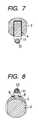
- FIG. 7is a horizontal cross sectional view showing a state that a tendon sheath of flexor muscle 22 is constricted to a head 2 ;
- FIG. 8is a horizontal cross sectional view showing a state that a tendon sheath of extensor muscle 23 is constricted to a head 5 .
- FIGS. 1 to 8show one embodiment in accordance with the present invention.
- reference numeral 1denotes an artificial knuckle joint
- reference numeral 2denotes a substantially semi-spherical head constituting the artificial knuckle joint 1
- reference numeral 3denotes an cuboid-shaped fitting piece provided to protrude on a back surface of the head 2
- reference numeral 4denotes a constriction member mounting groove formed on the back surface of the head 2 along a base end portion of the fitting piece 3 .
- the head 2is formed by a titanium alloy or a cobalt chrome alloy.
- Reference numeral 5denotes a socket provided with a recess portion 6 in a spherical surface shape so as to slidably contact with the head 2 in a freely bending manner
- reference numeral 7denotes an cuboid-shaped fitting piece provided to protrude on a back surface of the socket 5
- reference numeral 8denotes a pair of both side constriction member mounting holes formed in a top portion of the socket 5 in a communicating manner.
- the socket 5may be formed by a titanium alloy or a cobalt chrome alloy similarly to that of the head 2 , however, is preferably formed by a plastic being excellent in an abrasion resistance, for example, an engineering plastic as typified by an ultra macromolecule polyethylene.
- Reference numeral 9denotes a stem for a metacarpal bone made of a titanium alloy or a cobalt chrome alloy to be fitly attachable to the head 2
- reference numeral 10denotes a stem base portion formed in a substantially truncated conical shape and constituting the metacarpal bone stem 9
- reference numeral 11denotes a screw thread formed on an outer peripheral surface of the stem base portion 10
- reference numeral 12denotes a quadrangular fitting hole having a desired depth formed in a base end of the stem base portion 10 so as to fit to the fitting piece 3 of the head 2
- reference numeral 13denotes a screw hole formed in a front end side of the stem base portion 10 along an axis thereof so as to communicate with the fitting hole 12
- reference numeral 14denotes a locking screw with a hexagonal hole having a desired length which is engaged with the screw hole 13 so as to freely screw to move
- reference numeral 15denotes a pair of side tapered stem pieces having an elasticity and integrally
- the stem piece 15can be freely expanded outward by screwing the locking screw 14 so as to forcedly insert, and an outer peripheral surface thereof is formed in a rough surface shape without finishing the surface.
- Reference numeral 16denotes a stem for proximal phalanx structured such as to be fitly attachable to the socket 5 .
- the proximal phalanx stem 16is different from the metacarpal bone stem 9 in view of being formed in a slightly shorter shape than the metacarpal bone stem 9 , and is the same in the other portions, and the same reference numerals denotes the same portions.
- reference numeral 17denotes a constriction member such as a wire or the like
- reference numeral 18denotes metacarpal bone
- reference numeral 19denotes a bone marrow hole in the metacarpal bone 18
- reference numeral 20denotes a proximal phalanx
- reference numeral 21denotes a bone marrow hole of the proximal phalanx 20
- reference numeral 22denotes a tendon sheath of flexor muscle
- reference numeral 23denotes a tendon sheath of extensor muscle, respectively.
- a joint portion between the metacarpal bone 18 and the proximal phalanx 20is cut so as to expose each of the bone marrow holes 19 and 21 .
- the metacarpal bone stem 9 and the proximal phalanx stem 16are respectively inserted into the corresponding bone marrow holes 19 and 21 , and are screwed into opening end edges of the bone marrow holes 19 and 21 via the screw thread 11 of the stem base portion 10 .
- the front portions of the locking screws 14are forcedly inserted into the stem pieces 15 in the both sides while being screwed respectively, and the outer peripheral surfaces of the stem pieces 15 are in tight contact with the inner peripheral surfaces of the bone marrow holes 19 and 21 so as to be fixed.
- the stem pieces 15have an elasticity, the stem pieces 15 can be easily and tightly contacted without giving a damage within the bone marrow holes 19 and 21 , and further since the outer peripheral surfaces of the stem pieces 15 are formed in a rough surface shape, the bone can intrude into the depth of rough surface so as to generate a biological fixation with the elapse of time.
- the constriction members 17such as the wires or the like are mounted to the head 2 and the socket 5 via the mounting groove 4 and the mounting holes 8 , respectively.
- the head 2is fitly attached to the metacarpal bone stem 9 and the socket 5 is fitly attached to the proximal phalanx stem 16 , respectively by fitting the fitting pieces 3 and 7 to the corresponding fitting holes 12 , and further both are slidably contacted in a freely bending manner.
- the head 2 and the socket 5are structured such that the fitting pieces 3 and 7 are respectively fitted and attached to the fitting holes 12 in the metacarpal bone stem 9 and the proximal phalanx stem 16 , not only it is possible to freely select the fixing positions in the bone marrow holes 19 and 21 while rotating the metacarpal bone stem 9 and the proximal phalanx stem 16 at every 90 degrees, respectively, but also it is possible to adjust the fixing positions of the head 2 and the socket 5 while suitably adjusting fits thereof so as to freely adjust a tension of collateral ligament.
- the tendon sheath of flexor muscle 22is constricted to the head 2 via the constriction member 17 and the tendon sheath of extensor muscle 23 is constricted to the socket 5 (refer to FIGS. 6 to 8 ).
- the tendon sheath of flexor muscle 22 and the tendon sheath of extensor muscle 23are respectively constricted to the head 2 and the socket 5 , it is possible to securely prevent a movement to the ulna side and it is possible to effectively prevent an extension disability of the MP joint caused by a failure of the sutures in the tendon sheath of extensor muscle 23 or the like.
- an operationis completed by repairing the ligament and others in accordance with the known method (refer to FIG. 5 ).
- the head 2 and the socket 5are made in a spherical joint structure, however, they are not limited to this, and may be formed in a hinge joint structure. Further, the structure is made such that the tendon sheath of flexor muscle 22 is constricted to the head 2 and the tendon sheath of extensor muscle 23 is constricted to the socket 5 , respectively, however, on the contrary, the structure may be made such that the tendon sheath of flexor muscle 22 is constricted to the socket 5 and the tendon sheath of extensor muscle 23 is constricted to the head 2 , respectively.
- the mounting operation of the constriction members 17are executed via the mounting groove 4 and the mounting holes 8 , however, it is not limited to this, and the constriction members 17 may be mounted via the other known mounting structures.
- the embodiment mentioned aboveshows the artificial knuckle joint 1 for the MP joint, however, the structure is not limited to this, for example, the present invention can be also applied to an artificial knuckle joint for a PIP joint or an artificial elbow joint.
- the present invention described in the first aspectis structured as mentioned above, it is possible to expand the stem pieces 15 outward so as to tightly contact with and fix to inner peripheral surfaces of the bone marrow holes 19 and 21 while screwing the locking screws 14 so as to forcedly insert into the both side stem pieces 15 , and fit and attach the head 2 and the socket 5 respectively to the stem base portions 10 so that both are in slidably contact in a freely bending manner. Therefore, not only it is possible to rapidly, securely and easily perform the fixing operation, but also it is possible to smartly, easily and securely mount the head 2 and the socket 5 directly to the stems 9 and 16 in a very natural style without interfering with the screwed locking screw 14 .
- the present invention described in the second aspectis structured as mentioned above, not only it is possible to freely select positions for fixing within the bone marrow holes 19 and 21 while rotating the stems 9 and 16 at every 90 degrees, but also it is possible to adjust fixing positions of the head 2 and the socket 5 while adjusting fits, thereby freely adjusting a tension of a collateral ligament.
- the desired constriction members 17are mounted to the constriction member mounting portions 4 and 8 so as to constrict the tendon sheath of flexor muscle 22 and the tendon sheath of extensor muscle 23 to the head 2 and the socket 5 by the constriction members 17 , whereby it is possible to securely prevent a movement to the ulna side, and further it is possible to effectively prevent the extension disability of the MP joint or the like caused by the failure of the sutures of the tendon sheath of flexor muscle 22 and the tendon sheath of extensor muscle 23 .
Landscapes
- Health & Medical Sciences (AREA)
- Orthopedic Medicine & Surgery (AREA)
- Cardiology (AREA)
- Oral & Maxillofacial Surgery (AREA)
- Transplantation (AREA)
- Engineering & Computer Science (AREA)
- Biomedical Technology (AREA)
- Heart & Thoracic Surgery (AREA)
- Vascular Medicine (AREA)
- Life Sciences & Earth Sciences (AREA)
- Animal Behavior & Ethology (AREA)
- General Health & Medical Sciences (AREA)
- Public Health (AREA)
- Veterinary Medicine (AREA)
- Prostheses (AREA)
Abstract
Description
1. Field of the Invention
The present invention relates to an artificial joint such as an artificial knuckle joint, an artificial elbow joint and the like.
2. Description of the Prior Art
Conventionally, for example, a metacarpophalangeal joint of a finger (hereinafter, refer to an MP joint) is constituted by a metacarpal bone and a proximal phalanx, and a proximal interphalangeal joint (hereinafter, refer to a PIP joint) is constituted by a proximal phalanx and a phalanx media, however, when having an arthritis as typified by a rheumatoid arthritis, particularly joints, ligaments and tendons in hand and foot are gradually affected, so that a painful deformation, a significant limitation of motion or the like appears. As a countermeasure against the matter mentioned above, there has been generally executed an operation of replacing a joint portion deformed due to the arthritis by an artificial joint.
In this case, as the artificial joint mentioned above, there have been disclosed the following structures:
a. a structure in which stems are integrally formed in both ends of a middle flange portion around the middle flange portion with an elastic macromolecule material as typified by a silicon resin.
b. a spherical joint structure obtained by combining a spherical connection end with stems and a spherical surface recessed connection end with stems in a freely bending manner (refer to Japanese Utility Model Publication No. 2-29941 and Japanese Unexamined Patent Publication No. 9-38122).
c. a hinge joint structure obtained by pivoting a connection joint with stems each having an insertion hole by a pin in a freely bending manner (refer to Japanese Unexamined Patent Publication Nos. 59-91956 and 61-276553).
Accordingly, an operation to replace with the artificial joints mentioned above are done in accordance with a method of inserting a stem having a desired shape such as a rod shape, a tapered rod shape or the like into a bone marrow hole and fixing it via a bone cement, or a method of inserting a stem formed so as to fit to a required inner surface of the bone marrow hole into the bone marrow hole so as to fix.
However, the conventional artificial joint structured in the manner mentioned above can effectively achieve a joint function, but on the other hand, has a problem in a fixing method. For example, in the conventional method of inserting the stem formed in the tapered rod shape or the like into the bone marrow hole and fixing it via the bone cement, not only the fixing operation is very troublesome and needs a lot of work, but also there is a risk that a fixing force is easily weakened due to an aging of tissues within the bone marrow hole or the like, so that it is hard to hold the fixing force for a long time. Further, in the conventional method of inserting the stem formed so as to fit to the inner surface of the bone marrow hole into the bone marrow hole so as to fix, not only it is very troublesome to manufacture the stem so that a cost is increased, but also in the case that a shape suitability with respect to the tissues within the bone marrow hole lacks, there is a risk of a stress concentration which has conventionally been a great problem in view of a design.
An object of the present invention is to provide an artificial joint which can clear up the conventional problems mentioned above once for all, and can be rapidly, securely and easily fixed while being suited to an inner surface of a bone marrow hole by a novel structure absolutely different from the conventional one.
That is, in accordance with a first aspect of the present invention, there is provided an artificial joint comprising:
astem base portion 10 in which a desiredhead 2 and a desiredsocket 5 are in slidably contact with each other in a freely bending manner,stems head 2 and thesocket 5, and therespective stems screws 14 freely screwing to move along axial directions thereof; and
a pair ofstem pieces 15 having an elasticity provided to protrude on both front portions of thestem base portion 10,
wherein thelocking screws 14 are forcedly inserted within thestem pieces 15 so as to expand them outward, thereby making them tightly contact with and fix to inner surfaces ofbone marrow holes
Accordingly, the present invention described in the first aspect mentioned above is structured such as to expand thestem pieces 15 outward so as to tightly contact with and fix to inner peripheral surfaces of thebone marrow holes locking screws 14 so as to be forcedly inserted into the bothside stem pieces 15, and fitly attach thehead 2 and thesocket 5 respectively to thestem base portion 10 so as to be in slidable contact in a freely bending manner.
In accordance with a second aspect of the present invention, there is provided an artificial joint as recited in the first aspect, wherein cuboid-shaped fitting pieces head 2 and thesocket 5,quadrangular fitting holes 12 are formed in thestem base portions 10 in such a manner as to correspond to thefitting pieces fitting pieces fitting holes 12.
Accordingly, since the invention described in the second aspect mentioned above is structured such as to fit and attach the cuboid-shapedfitting pieces quadrangular fitting holes 12, not only it is possible to freely select positions for fixing within thebone marrow holes stems head 2 and thesocket 5 while adjusting fits thereof, thereby freely adjusting a tension of a collateral ligament.
In accordance with a third aspect of the present invention, there is provided an artificial joint as recited in the first aspect or the second aspect, wherein a constrictionmember mounting groove 4 is formed in one of thehead 2 and thesocket 5 so as to constrict a tendon sheath offlexor muscle 22, and constrictionmember mounting holes 8 are formed in the other of thehead 2 and thesocket 5 so as to constrict a tendon sheath ofextensor muscle 23.
Accordingly, since the invention described in the third aspect is structured such that desiredconstriction members 17 are mounted to the constrictionmember mounting groove 4 andholes 8 so as to constrict the tendon sheath offlexor muscle 22 and the tendon sheath ofextensor muscle 23 to thehead 2 and thesocket 5 by theconstriction members 17, it is possible to securely prevent a movement to the ulna side.
FIG. 1 is an exploded perspective view showing an embodiment in accordance with the present invention;
FIG. 2 is a side view showing an assembled state
FIG. 3 is a horizontal cross sectional view of FIG. 2
FIG. 4 is a vertical cross sectional view of FIG. 2;
FIG. 5 is a side view showing a state of being used in an MP joint portion;
FIG. 6 is an enlarged cross sectional view of a main portion thereof;
FIG. 7 is a horizontal cross sectional view showing a state that a tendon sheath offlexor muscle 22 is constricted to ahead 2; and
FIG. 8 is a horizontal cross sectional view showing a state that a tendon sheath ofextensor muscle 23 is constricted to ahead 5.
A description will be given below of an embodiment in accordance with the present invention on the basis of one embodiment shown in the accompanying drawings.
FIGS. 1 to8 show one embodiment in accordance with the present invention. In the drawing,reference numeral 1 denotes an artificial knuckle joint,reference numeral 2 denotes a substantially semi-spherical head constituting theartificial knuckle joint 1,reference numeral 3 denotes an cuboid-shaped fitting piece provided to protrude on a back surface of thehead 2, andreference numeral 4 denotes a constriction member mounting groove formed on the back surface of thehead 2 along a base end portion of thefitting piece 3. Further, thehead 2 is formed by a titanium alloy or a cobalt chrome alloy.Reference numeral 5 denotes a socket provided with arecess portion 6 in a spherical surface shape so as to slidably contact with thehead 2 in a freely bending manner,reference numeral 7 denotes an cuboid-shaped fitting piece provided to protrude on a back surface of thesocket 5, andreference numeral 8 denotes a pair of both side constriction member mounting holes formed in a top portion of thesocket 5 in a communicating manner. Further, thesocket 5 may be formed by a titanium alloy or a cobalt chrome alloy similarly to that of thehead 2, however, is preferably formed by a plastic being excellent in an abrasion resistance, for example, an engineering plastic as typified by an ultra macromolecule polyethylene.
In addition,reference numeral 17 denotes a constriction member such as a wire or the like,reference numeral 18 denotes metacarpal bone,reference numeral 19 denotes a bone marrow hole in themetacarpal bone 18,reference numeral 20 denotes a proximal phalanx,reference numeral 21 denotes a bone marrow hole of theproximal phalanx 20,reference numeral 22 denotes a tendon sheath of flexor muscle, andreference numeral 23 denotes a tendon sheath of extensor muscle, respectively.
Next, a description will be given of a using method and an operation of an embodiment structured as mentioned above.
At first, a joint portion between themetacarpal bone 18 and theproximal phalanx 20 is cut so as to expose each of thebone marrow holes metacarpal bone stem 9 and theproximal phalanx stem 16 are respectively inserted into the correspondingbone marrow holes bone marrow holes screw thread 11 of thestem base portion 10. Next, the front portions of thelocking screws 14 are forcedly inserted into thestem pieces 15 in the both sides while being screwed respectively, and the outer peripheral surfaces of thestem pieces 15 are in tight contact with the inner peripheral surfaces of thebone marrow holes stem pieces 15 have an elasticity, thestem pieces 15 can be easily and tightly contacted without giving a damage within thebone marrow holes stem pieces 15 are formed in a rough surface shape, the bone can intrude into the depth of rough surface so as to generate a biological fixation with the elapse of time.
When the fixation of themetacarpal bone stem 9 and theproximal phalanx stem 16 is completed, theconstriction members 17 such as the wires or the like are mounted to thehead 2 and thesocket 5 via themounting groove 4 and themounting holes 8, respectively. Next, thehead 2 is fitly attached to themetacarpal bone stem 9 and thesocket 5 is fitly attached to theproximal phalanx stem 16, respectively by fitting thefitting pieces corresponding fitting holes 12, and further both are slidably contacted in a freely bending manner. At this time, since thehead 2 and thesocket 5 are structured such that thefitting pieces fitting holes 12 in themetacarpal bone stem 9 and theproximal phalanx stem 16, not only it is possible to freely select the fixing positions in thebone marrow holes metacarpal bone stem 9 and theproximal phalanx stem 16 at every 90 degrees, respectively, but also it is possible to adjust the fixing positions of thehead 2 and thesocket 5 while suitably adjusting fits thereof so as to freely adjust a tension of collateral ligament. Thereafter, the tendon sheath offlexor muscle 22 is constricted to thehead 2 via theconstriction member 17 and the tendon sheath ofextensor muscle 23 is constricted to the socket5 (refer to FIGS. 6 to8). At this time, since the tendon sheath offlexor muscle 22 and the tendon sheath ofextensor muscle 23 are respectively constricted to thehead 2 and thesocket 5, it is possible to securely prevent a movement to the ulna side and it is possible to effectively prevent an extension disability of the MP joint caused by a failure of the sutures in the tendon sheath ofextensor muscle 23 or the like. When the constriction of the tendon sheath offlexor muscle 22 and the tendon sheath ofextensor muscle 23 is finished, an operation is completed by repairing the ligament and others in accordance with the known method (refer to FIG.5).
In this case, in the embodiment mentioned above, thehead 2 and thesocket 5 are made in a spherical joint structure, however, they are not limited to this, and may be formed in a hinge joint structure. Further, the structure is made such that the tendon sheath offlexor muscle 22 is constricted to thehead 2 and the tendon sheath ofextensor muscle 23 is constricted to thesocket 5, respectively, however, on the contrary, the structure may be made such that the tendon sheath offlexor muscle 22 is constricted to thesocket 5 and the tendon sheath ofextensor muscle 23 is constricted to thehead 2, respectively. Further, the mounting operation of theconstriction members 17 are executed via themounting groove 4 and themounting holes 8, however, it is not limited to this, and theconstriction members 17 may be mounted via the other known mounting structures. In this case, the embodiment mentioned above shows theartificial knuckle joint 1 for the MP joint, however, the structure is not limited to this, for example, the present invention can be also applied to an artificial knuckle joint for a PIP joint or an artificial elbow joint.
Since the present invention described in the first aspect is structured as mentioned above, it is possible to expand thestem pieces 15 outward so as to tightly contact with and fix to inner peripheral surfaces of the bone marrow holes19 and21 while screwing the locking screws14 so as to forcedly insert into the bothside stem pieces 15, and fit and attach thehead 2 and thesocket 5 respectively to thestem base portions 10 so that both are in slidably contact in a freely bending manner. Therefore, not only it is possible to rapidly, securely and easily perform the fixing operation, but also it is possible to smartly, easily and securely mount thehead 2 and thesocket 5 directly to thestems screw 14. Further, since it is possible to insert another stem by utilizing the gap generated by the outer expansion of thestems
Since the present invention described in the second aspect is structured as mentioned above, not only it is possible to freely select positions for fixing within the bone marrow holes19 and21 while rotating thestems head 2 and thesocket 5 while adjusting fits, thereby freely adjusting a tension of a collateral ligament.
Since the present invention described in the third aspect is structured as mentioned above, the desiredconstriction members 17 are mounted to the constrictionmember mounting portions flexor muscle 22 and the tendon sheath ofextensor muscle 23 to thehead 2 and thesocket 5 by theconstriction members 17, whereby it is possible to securely prevent a movement to the ulna side, and further it is possible to effectively prevent the extension disability of the MP joint or the like caused by the failure of the sutures of the tendon sheath offlexor muscle 22 and the tendon sheath ofextensor muscle 23.
Claims (14)
1. An artificial joint comprising:
a head (2) having a spherical convex surface at one end and a first fitting piece (3) with a quadrangular configuration in cross section at the other end;
a socket (5) having a spherical concave surface (6) at one end and a second fitting piece (7) with a quadrangular configuration in cross section at the other end, said head (2) and said socket (5) being interconnected so that said spherical convex and concave surfaces slidably contacts with each other;
a first stem (9) having at one end a first stem base portion (10) provided with a first fitting hole (12) having a quadrangular configuration in cross section and a first threaded hole (13) and at the other end a first pair of stem pieces (15) which extend from the first stem base portion (16) and are spaced substantially in parallel with each other, said first fitting piece (3) of said head (2) being engaged with said first fitting hole (12);
a second stem (16) having at one end a second stem base portion (10) provided with a second fitting hole (12) having a quadrangular configuration in cross section and a second threaded hole (13) and at the other end a second pair of stem pieces (15) which extend from said second stem base portion (10) and are spaced substantially in parallel with each other, said second fitting piece (7) of said socket (5) being engaged with said second filling hole (12);
a first locking screw (14) forcedly screwed into said first threaded hole (13) so as to expand said first pair of stem pieces (15) outwardly; and
a second locking screw (14) forcedly screwed into said second threaded hole (13) so as to expand said second pair of stem pieces (15) outwardly,
wherein said head (2) is provided with a first constriction member mounting structure, and
said socket (5) is provided with a second constriction member mounting structure;
a first constriction member, mounted to said first constriction member mounting structure, to constrict a first tendon sheath; and
a second constriction member, mounted to said second constriction member mounting structure, to constrict a second tendon sheath.
2. The artificial joint ofclaim 1 , wherein said constriction member mounting structure includes a constriction member mounting groove (4) formed in one of the head (2) and the socket (5) so as to constrict a tendon sheath of flexor muscle (22), and a constriction member mounting holes (8) formed in the other of the head (2) and the socket (5) so as to constrict a tendon sheath of extensor muscle (23).
3. The artificial joint ofclaim 1 , wherein a constriction member mounting groove (4) is formed in one of the head (2) and the socket (5) so as to constrict a tendon sheath of flexor muscle (22), and a constriction member mounting holes (8) are formed in the other of the head (2) and the socket (5) so as to constrict a tendon sheath of extensor muscle (23).
4. The artificial joint ofclaim 1 , wherein either of said first or said second constriction member mounting structure comprises a constriction member mounting groove; and
the other of either said first or said second constriction member mounting structure comprises constriction member mounting holes (8).
5. The artificial joint ofclaim 4 , wherein said constriction member mounting groove on a back surface of said head (2) along a base end portion of said first fitting piece (3).
6. The artificial joint ofclaim 4 , wherein said constriction member mounting holes (8) comprise a plurality of side constriction member mounting holes formed in a top portion of said socket (5) in a communicating manner.
7. The artificial joint ofclaim 1 , wherein one of either said head (2) or said socket (5)is provided with a first constriction member mounting groove (4) while the other of either said head (2) or said socket (5) is provided with a plurality of constriction member mounting holes (8).
8. The artificial joint ofclaim 1 , wherein an outer surface of said stem pieces (15) are textured to promote bone growth fixation to said outer surface.
9. The artificial joint ofclaim 1 , wherein said first and said second constriction members comprise wires.
10. The artificial joint ofclaim 1 , wherein said first and said second constriction members prevent movement of said artificial joint to an ulna side of a finger.
11. An artificial joint comprising:
a head comprising a hemi-spherical convex surface and a first fitting piece opposite said hemi-spherical convex surface;
a socket comprising a hemi-spherical concave surface and a second fitting piece opposite said hemi-spherical concave surface, said head and said socket being interconnected so that said hemi-spherical convex and concave surfaces slidably contact with each other;
a first stem comprising at one end a first stem base portion provided with a first fitting hole and at the other end a first pair of outwardly biased stem pieces which extend from the first stem base portion and are spaced substantially in parallel with each other, said first fitting piece of said head being engaged with said first fitting hole and wherein said first pair of stem pieces are outwardly expandable;
a second stem having at one end a second stem base portion provided with a second fitting hole and at the other end a second pair of outwardly biased stem pieces which extend from said second stem base portion and are spaced substantially in parallel with each other, said second fitting piece of said socket being engaged with said second fitting hole, and wherein said second pair of stem pieces are outwardly expandable;
a first constriction member, attached to said head, to constrict a first tendon sheath; and
a second constriction member, attached to said socket, to constrict a second tendon sheath.
12. The artificial joint ofclaim 11 , wherein said first constriction member is attached to a first constriction member mounting structure formed on said head, and
said second constriction member is attached to a second constriction member mounting structure formed on said socket.
13. The artificial joint ofclaim 12 , wherein either of said first or said second constriction member mounting structure comprises a constriction member mounting groove; and
the other of either said first or said second constriction member mounting structures comprises constriction member mounting holes.
14. The artificial joint ofclaim 11 , wherein an outer surface of said stem pieces are textured to promote bone growth fixation to said outer surface.
Applications Claiming Priority (2)
| Application Number | Priority Date | Filing Date | Title |
|---|---|---|---|
| JP2001256521AJP3614802B2 (en) | 2001-08-27 | 2001-08-27 | Artificial joint |
| JP2001-256521 | 2001-08-27 |
Publications (2)
| Publication Number | Publication Date |
|---|---|
| US20030040805A1 US20030040805A1 (en) | 2003-02-27 |
| US6811568B2true US6811568B2 (en) | 2004-11-02 |
Family
ID=19084324
Family Applications (1)
| Application Number | Title | Priority Date | Filing Date |
|---|---|---|---|
| US10/114,788Expired - LifetimeUS6811568B2 (en) | 2001-08-27 | 2002-04-02 | Artificial joint |
Country Status (3)
| Country | Link |
|---|---|
| US (1) | US6811568B2 (en) |
| JP (1) | JP3614802B2 (en) |
| CH (1) | CH694953A5 (en) |
Cited By (58)
| Publication number | Priority date | Publication date | Assignee | Title |
|---|---|---|---|---|
| US20060074492A1 (en)* | 2004-09-09 | 2006-04-06 | Theo Frey | Endoprosthesis for a metatarsophalangeal joint |
| US20060116771A1 (en)* | 2004-12-01 | 2006-06-01 | Cooney William P Iii | Radial-capitellar implant |
| US20060142866A1 (en)* | 2004-08-23 | 2006-06-29 | Mark Baratz | Radial head implant apparatuses and methods |
| US20070185584A1 (en)* | 2006-02-02 | 2007-08-09 | Kaufmann Robert A | Small joint hemiarthroplasty |
| US7326252B2 (en) | 2002-12-20 | 2008-02-05 | Smith & Nephew, Inc. | High performance knee prostheses |
| US20080154385A1 (en)* | 2006-06-20 | 2008-06-26 | Finsbury (Development) Limited | Prosthesis |
| US20080177262A1 (en)* | 2005-04-14 | 2008-07-24 | Marc Augoyard | Intramedullar Osteosynthetic Device of Two Bone Parts, In Particular of the Hand and/or Foot |
| US7445639B2 (en) | 2001-02-23 | 2008-11-04 | Biomet Manufacturing Corp. | Knee joint prosthesis |
| US20080288079A1 (en)* | 2007-02-10 | 2008-11-20 | Small Bone Innovations, Inc. | Radial Head Implant and Related Instrument |
| US7497874B1 (en) | 2001-02-23 | 2009-03-03 | Biomet Manufacturing Corp. | Knee joint prosthesis |
| US20090125108A1 (en)* | 2007-11-08 | 2009-05-14 | Linares Medical Devices, Llc | Artificial knee implant including liquid ballast supporting / rotating surfaces and incorporating flexible multi-material and natural lubricant retaining matrix applied to a joint surface |
| US20090248166A1 (en)* | 2008-03-26 | 2009-10-01 | Linares Miguel A | Joint construction, such as for use by athletes |
| US20100131014A1 (en)* | 2007-03-20 | 2010-05-27 | Memometal Technologies | Osteosynthesis device |
| US20100222892A1 (en)* | 2007-11-08 | 2010-09-02 | Linares Medical Devices, Llc | Joint assembly incorporating undercut surface design to entrap accumulating wear debris from plastic joint assembly |
| US7875082B2 (en)* | 2008-05-09 | 2011-01-25 | Remi Sciences, Inc. | Ulnar head prosthesis system |
| US20110035012A1 (en)* | 2008-02-25 | 2011-02-10 | Linares Medical Devices, Llc | Artificial wear resistant plug for mounting to existing joint bone |
| US20110077652A1 (en)* | 2009-01-08 | 2011-03-31 | Philippe Bellemere | Intramedullary anchoring stem for an orthopaedic implant head |
| US20110144644A1 (en)* | 2008-09-09 | 2011-06-16 | Memometal Technologies | Resorptive intramedullary implant between two bones or two bone fragments |
| US8052755B2 (en)* | 2008-05-09 | 2011-11-08 | Remi Sciences, Inc. | Ulnar head prosthesis system |
| US20120078376A1 (en)* | 2002-10-24 | 2012-03-29 | Biomet Manufacturing Corp. | Method And Apparatus For Wrist Arthroplasty |
| US8157869B2 (en) | 2007-01-10 | 2012-04-17 | Biomet Manufacturing Corp. | Knee joint prosthesis system and method for implantation |
| US8163028B2 (en) | 2007-01-10 | 2012-04-24 | Biomet Manufacturing Corp. | Knee joint prosthesis system and method for implantation |
| US8187280B2 (en) | 2007-10-10 | 2012-05-29 | Biomet Manufacturing Corp. | Knee joint prosthesis system and method for implantation |
| US8287538B2 (en) | 2008-01-14 | 2012-10-16 | Conventus Orthopaedics, Inc. | Apparatus and methods for fracture repair |
| US8328873B2 (en) | 2007-01-10 | 2012-12-11 | Biomet Manufacturing Corp. | Knee joint prosthesis system and method for implantation |
| US8562616B2 (en) | 2007-10-10 | 2013-10-22 | Biomet Manufacturing, Llc | Knee joint prosthesis system and method for implantation |
| JP2014500049A (en)* | 2010-10-29 | 2014-01-09 | ジーエス ディベロップメント アクティエボラーグ | Artificial joint |
| US8641770B2 (en) | 2012-01-26 | 2014-02-04 | Aptis Medical, Llc | Prosthesis for the basal joint of the thumb |
| US8685024B2 (en) | 2010-04-14 | 2014-04-01 | Arrowhead Medical Device Technologies, Llc | Intramedullary fixation device and methods for bone fixation and stabilization |
| US20140114365A1 (en)* | 2005-05-10 | 2014-04-24 | Acumed Llc | Bone connector with pivotable joint |
| US8858644B2 (en) | 2009-01-08 | 2014-10-14 | Memometal Technologies | Orthopaedic implant for arthroplasty of the fingers |
| US8906022B2 (en) | 2010-03-08 | 2014-12-09 | Conventus Orthopaedics, Inc. | Apparatus and methods for securing a bone implant |
| US8926705B2 (en) | 2010-05-10 | 2015-01-06 | Linares Medical Devices, Llc | Implantable joint assembly featuring debris entrapment chamber subassemblies along with opposing magnetic fields generated between articulating implant components in order to minimize frictional force and associated wear |
| US8926709B2 (en) | 2010-08-12 | 2015-01-06 | Smith & Nephew, Inc. | Structures for use in orthopaedic implant fixation and methods of installation onto a bone |
| US8961518B2 (en) | 2010-01-20 | 2015-02-24 | Conventus Orthopaedics, Inc. | Apparatus and methods for bone access and cavity preparation |
| US20150342745A1 (en)* | 2014-06-02 | 2015-12-03 | Stryker European Holdings I, Llc | Metacarpal rod anchor for a trapezometacarpal prosthesis |
| US9452002B2 (en) | 2013-03-13 | 2016-09-27 | Arrowhead Medical Device Technologies, Llc | Hammertoe implant with enhanced gripping surfaces |
| US9474561B2 (en) | 2013-11-19 | 2016-10-25 | Wright Medical Technology, Inc. | Two-wire technique for installing hammertoe implant |
| US9498273B2 (en) | 2010-06-02 | 2016-11-22 | Wright Medical Technology, Inc. | Orthopedic implant kit |
| US9498266B2 (en) | 2014-02-12 | 2016-11-22 | Wright Medical Technology, Inc. | Intramedullary implant, system, and method for inserting an implant into a bone |
| US9504582B2 (en) | 2012-12-31 | 2016-11-29 | Wright Medical Technology, Inc. | Ball and socket implants for correction of hammer toes and claw toes |
| US9539097B2 (en) | 2007-11-08 | 2017-01-10 | Linares Medical Devices, Llc | Hip and knee joint assemblies incorporating debris collection architecture between the ball and seat interface |
| US9545274B2 (en) | 2014-02-12 | 2017-01-17 | Wright Medical Technology, Inc. | Intramedullary implant, system, and method for inserting an implant into a bone |
| US9603643B2 (en) | 2010-06-02 | 2017-03-28 | Wright Medical Technology, Inc. | Hammer toe implant with expansion portion for retrograde approach |
| US9642711B2 (en) | 2003-10-17 | 2017-05-09 | Smith & Nephew, Inc. | High flexion articular insert |
| US9717543B2 (en) | 2013-03-13 | 2017-08-01 | Arrowhead Medical Device Technologies, Llc | Methods and implants for treating hammertoe and other deformities |
| US9724140B2 (en) | 2010-06-02 | 2017-08-08 | Wright Medical Technology, Inc. | Tapered, cylindrical cruciform hammer toe implant and method |
| US9724139B2 (en) | 2013-10-01 | 2017-08-08 | Wright Medical Technology, Inc. | Hammer toe implant and method |
| US9730739B2 (en) | 2010-01-15 | 2017-08-15 | Conventus Orthopaedics, Inc. | Rotary-rigid orthopaedic rod |
| US9730799B2 (en) | 2006-06-30 | 2017-08-15 | Smith & Nephew, Inc. | Anatomical motion hinged prosthesis |
| US9757168B2 (en) | 2015-03-03 | 2017-09-12 | Howmedica Osteonics Corp. | Orthopedic implant and methods of implanting and removing same |
| US9808296B2 (en) | 2014-09-18 | 2017-11-07 | Wright Medical Technology, Inc. | Hammertoe implant and instrument |
| US10022132B2 (en) | 2013-12-12 | 2018-07-17 | Conventus Orthopaedics, Inc. | Tissue displacement tools and methods |
| US10080597B2 (en) | 2014-12-19 | 2018-09-25 | Wright Medical Technology, Inc. | Intramedullary anchor for interphalangeal arthrodesis |
| US10349987B2 (en) | 2010-04-14 | 2019-07-16 | Arrowhead Medical Device Technologies, Llc | Intramedullary fixation devices |
| US10470807B2 (en) | 2016-06-03 | 2019-11-12 | Stryker European Holdings I, Llc | Intramedullary implant and method of use |
| US10918426B2 (en) | 2017-07-04 | 2021-02-16 | Conventus Orthopaedics, Inc. | Apparatus and methods for treatment of a bone |
| US11596419B2 (en) | 2017-03-09 | 2023-03-07 | Flower Orthopedics Corporation | Plating depth gauge and countersink instrument |
Families Citing this family (18)
| Publication number | Priority date | Publication date | Assignee | Title |
|---|---|---|---|---|
| US9155626B2 (en) | 2012-09-10 | 2015-10-13 | Acumed Llc | Radial head prosthesis with floating articular member |
| ES2282594T3 (en)* | 2003-10-31 | 2007-10-16 | Orthofix S.R.L. | ARTICULAR PROTESIS FOR METACARPOFALANGICO OR INTERFALANGICO.l use. |
| JP4607948B2 (en) | 2004-03-11 | 2011-01-05 | マヨ ファウンデーション フォー メディカル エデュケーション アンド リサーチ | Bone replacement system |
| DE202007009620U1 (en)* | 2007-07-09 | 2007-11-22 | Zrinski Ag | Articulated prosthesis with an anti-twist device |
| DE202007009619U1 (en)* | 2007-07-09 | 2007-11-22 | Zrinski Ag | Articulated prosthesis with expandable shaft |
| KR100898957B1 (en)* | 2008-10-02 | 2009-05-25 | (주) 코리아나메디칼 | Prosthetic Coupling Stem |
| CA2829196A1 (en)* | 2010-03-08 | 2011-09-15 | Conventus Orthopaedics, Inc. | Apparatus and methods for bone repair |
| US8840673B2 (en) | 2011-09-21 | 2014-09-23 | Linares Medical Devices, Llc | Implantable elbow joint assembly with spherical inter-support |
| US8974538B2 (en)* | 2013-03-15 | 2015-03-10 | Steven M. Teeny | Orthopedic spacer |
| CN103445888B (en)* | 2013-09-11 | 2015-04-01 | 徐永清 | Externally clamping fixed high-functionality artificial wrist joint prosthesis device |
| US10098749B2 (en) | 2015-07-31 | 2018-10-16 | Ryan A. Jefferis | Proximal interphalangeal joint prothesis |
| US10682237B2 (en)* | 2015-09-03 | 2020-06-16 | Cmc Sert Ltd. | Prosthesis for replacing joint in a human hand or foot |
| US9763792B2 (en) | 2015-10-01 | 2017-09-19 | Acumed Llc | Radial head prosthesis with rotate-to-lock interface |
| CN110013362A (en)* | 2019-04-26 | 2019-07-16 | 中国人民解放军联勤保障部队第九二〇医院 | A highly flexible bionic total finger joint replacement |
| CN113425471A (en)* | 2021-06-30 | 2021-09-24 | 北京市春立正达医疗器械股份有限公司 | Self-locking metacarpophalangeal joint prosthesis |
| CN113456316A (en)* | 2021-06-30 | 2021-10-01 | 北京市春立正达医疗器械股份有限公司 | Novel wrist joint prosthesis |
| CN116834071A (en)* | 2023-08-16 | 2023-10-03 | 深圳忆海原识科技有限公司 | Force bearing component of tendon transmission robot, palm knuckle and robot |
| CN118105207B (en)* | 2024-03-02 | 2025-05-27 | 北京德益达美医疗科技有限公司 | Ligament reconstruction fixation device with bifurcated structure |
Citations (18)
| Publication number | Priority date | Publication date | Assignee | Title |
|---|---|---|---|---|
| US3805302A (en)* | 1971-10-08 | 1974-04-23 | R Mathys | Finger joint prothesis |
| US4013071A (en)* | 1974-11-11 | 1977-03-22 | Lior Rosenberg | Fasteners particularly useful as orthopedic screws |
| US4349922A (en)* | 1979-02-22 | 1982-09-21 | Agee John M | Joint prosthesis with improved articulation means |
| JPS5991956A (en) | 1982-11-19 | 1984-05-26 | 京セラ株式会社 | Artificial finger joint |
| JPS61276553A (en) | 1985-05-31 | 1986-12-06 | 京セラ株式会社 | Artificial finger joint |
| US4759768A (en)* | 1987-02-11 | 1988-07-26 | Thierry Hermann | Joint prosthesis, in particular finger joint prosthesis |
| JPH0229941A (en) | 1988-07-19 | 1990-01-31 | Canon Inc | Optical information reproducing and erasing method |
| US4955916A (en)* | 1989-05-01 | 1990-09-11 | Techmedica, Inc. | Thumb joint prosthesis |
| US5011497A (en)* | 1987-10-29 | 1991-04-30 | Atos Medical Ab | Joint prosthesis |
| US5062851A (en)* | 1989-04-25 | 1991-11-05 | Medevelop Ab | Anchoring element for supporting a joint mechanism of a finger or other reconstructed joint |
| US5147386A (en)* | 1988-08-22 | 1992-09-15 | Techmedica, Inc. | Securable pistoning finger prosthesis |
| FR2705559A1 (en)* | 1993-05-28 | 1994-12-02 | Lafosse Laurent | Finger joint prosthesis with shield |
| US5425777A (en)* | 1992-12-23 | 1995-06-20 | Sarkisian; James S. | Artificial finger joint |
| JPH0938122A (en) | 1995-07-28 | 1997-02-10 | M Ii Syst:Kk | Artificial finger joint |
| JPH11332893A (en)* | 1998-05-21 | 1999-12-07 | Eidooru:Kk | Fixing structure of artificial joint |
| US6099571A (en)* | 1997-07-16 | 2000-08-08 | Knapp; John G. | Joint prosthesis |
| US6475242B1 (en)* | 1996-03-13 | 2002-11-05 | Dale G. Bramlet | Arthroplasty joint assembly |
| US6575975B2 (en)* | 2000-04-19 | 2003-06-10 | Synthes (U.S.A.) | Bone fixation method |
- 2001
- 2001-08-27JPJP2001256521Apatent/JP3614802B2/ennot_activeExpired - Fee Related
- 2002
- 2002-04-02USUS10/114,788patent/US6811568B2/ennot_activeExpired - Lifetime
- 2002-04-23CHCH00685/02Apatent/CH694953A5/ennot_activeIP Right Cessation
Patent Citations (18)
| Publication number | Priority date | Publication date | Assignee | Title |
|---|---|---|---|---|
| US3805302A (en)* | 1971-10-08 | 1974-04-23 | R Mathys | Finger joint prothesis |
| US4013071A (en)* | 1974-11-11 | 1977-03-22 | Lior Rosenberg | Fasteners particularly useful as orthopedic screws |
| US4349922A (en)* | 1979-02-22 | 1982-09-21 | Agee John M | Joint prosthesis with improved articulation means |
| JPS5991956A (en) | 1982-11-19 | 1984-05-26 | 京セラ株式会社 | Artificial finger joint |
| JPS61276553A (en) | 1985-05-31 | 1986-12-06 | 京セラ株式会社 | Artificial finger joint |
| US4759768A (en)* | 1987-02-11 | 1988-07-26 | Thierry Hermann | Joint prosthesis, in particular finger joint prosthesis |
| US5011497A (en)* | 1987-10-29 | 1991-04-30 | Atos Medical Ab | Joint prosthesis |
| JPH0229941A (en) | 1988-07-19 | 1990-01-31 | Canon Inc | Optical information reproducing and erasing method |
| US5147386A (en)* | 1988-08-22 | 1992-09-15 | Techmedica, Inc. | Securable pistoning finger prosthesis |
| US5062851A (en)* | 1989-04-25 | 1991-11-05 | Medevelop Ab | Anchoring element for supporting a joint mechanism of a finger or other reconstructed joint |
| US4955916A (en)* | 1989-05-01 | 1990-09-11 | Techmedica, Inc. | Thumb joint prosthesis |
| US5425777A (en)* | 1992-12-23 | 1995-06-20 | Sarkisian; James S. | Artificial finger joint |
| FR2705559A1 (en)* | 1993-05-28 | 1994-12-02 | Lafosse Laurent | Finger joint prosthesis with shield |
| JPH0938122A (en) | 1995-07-28 | 1997-02-10 | M Ii Syst:Kk | Artificial finger joint |
| US6475242B1 (en)* | 1996-03-13 | 2002-11-05 | Dale G. Bramlet | Arthroplasty joint assembly |
| US6099571A (en)* | 1997-07-16 | 2000-08-08 | Knapp; John G. | Joint prosthesis |
| JPH11332893A (en)* | 1998-05-21 | 1999-12-07 | Eidooru:Kk | Fixing structure of artificial joint |
| US6575975B2 (en)* | 2000-04-19 | 2003-06-10 | Synthes (U.S.A.) | Bone fixation method |
Cited By (137)
| Publication number | Priority date | Publication date | Assignee | Title |
|---|---|---|---|---|
| US7497874B1 (en) | 2001-02-23 | 2009-03-03 | Biomet Manufacturing Corp. | Knee joint prosthesis |
| US7445639B2 (en) | 2001-02-23 | 2008-11-04 | Biomet Manufacturing Corp. | Knee joint prosthesis |
| US10085842B2 (en) | 2002-10-24 | 2018-10-02 | Biomet Manufacturing, Llc | Method and apparatus for wrist arthroplasty |
| US20120078376A1 (en)* | 2002-10-24 | 2012-03-29 | Biomet Manufacturing Corp. | Method And Apparatus For Wrist Arthroplasty |
| US8940055B2 (en)* | 2002-10-24 | 2015-01-27 | Biomet Manufacturing, Llc | Method and apparatus for wrist arthroplasty |
| US9402729B2 (en) | 2002-12-20 | 2016-08-02 | Smith & Nephew, Inc. | High performance knee prostheses |
| US7922771B2 (en) | 2002-12-20 | 2011-04-12 | Smith & Nephew, Inc. | High performance knee prostheses |
| US10149768B2 (en) | 2002-12-20 | 2018-12-11 | Smith & Nephew, Inc. | High performance knee prostheses |
| US11369477B2 (en) | 2002-12-20 | 2022-06-28 | Smith & Nephew, Inc. | High performance knee prostheses |
| US8394148B2 (en) | 2002-12-20 | 2013-03-12 | Smith & Nephew, Inc. | Tibial component of high performance knee prosthesis |
| US9707087B2 (en) | 2002-12-20 | 2017-07-18 | Smith & Nephew, Inc. | High performance knee prosthesis |
| US8398716B2 (en) | 2002-12-20 | 2013-03-19 | Smith & Nephew, Inc. | High performance knee prostheses with posterior cam |
| US7326252B2 (en) | 2002-12-20 | 2008-02-05 | Smith & Nephew, Inc. | High performance knee prostheses |
| US8425617B2 (en) | 2002-12-20 | 2013-04-23 | Smith & Nephew, Inc. | Knee prostheses with convex slope on portion of tibial articular surface |
| US8394147B2 (en) | 2002-12-20 | 2013-03-12 | Smith & Nephew, Inc. | High performance femoral knee prostheses |
| US9320605B2 (en) | 2002-12-20 | 2016-04-26 | Smith & Nephew, Inc. | High performance knee prostheses |
| US8398715B2 (en) | 2002-12-20 | 2013-03-19 | Smith & Nephew, Inc. | High performance knee prostheses with converging anterior and posterior portions |
| US8449618B2 (en) | 2002-12-20 | 2013-05-28 | Smith & Nephew, Inc. | High performance knee prostheses |
| US8603178B2 (en) | 2002-12-20 | 2013-12-10 | Smith & Nephew, Inc. | Knee prostheses with convex portion on tibial lateral articular surface |
| US8652210B2 (en) | 2002-12-20 | 2014-02-18 | Smith & Nephew, Inc. | Femoral prostheses with lateral buttress for patella |
| US8647389B2 (en) | 2002-12-20 | 2014-02-11 | Smith & Nephew, Inc. | High performance knee prostheses |
| US8403992B2 (en) | 2002-12-20 | 2013-03-26 | Smith & Nephew, Inc. | High performance knee prostheses |
| US9642711B2 (en) | 2003-10-17 | 2017-05-09 | Smith & Nephew, Inc. | High flexion articular insert |
| US20060142866A1 (en)* | 2004-08-23 | 2006-06-29 | Mark Baratz | Radial head implant apparatuses and methods |
| US7740661B2 (en)* | 2004-08-23 | 2010-06-22 | Integra Lifesciences Corporation | Radial head implant apparatuses and methods |
| US20060074492A1 (en)* | 2004-09-09 | 2006-04-06 | Theo Frey | Endoprosthesis for a metatarsophalangeal joint |
| US9655726B2 (en) | 2004-12-01 | 2017-05-23 | Mayo Foundation For Medical Research And Education | Radial-capitellar implant |
| US20060116771A1 (en)* | 2004-12-01 | 2006-06-01 | Cooney William P Iii | Radial-capitellar implant |
| US7160329B2 (en) | 2004-12-01 | 2007-01-09 | Mayo Foundation For Medical Research And Education | Radial-capitellar implant |
| US20070073409A1 (en)* | 2004-12-01 | 2007-03-29 | Mayo Foundation For Medical Research And Education | Radial-capitellar implant |
| US9283007B2 (en) | 2005-04-14 | 2016-03-15 | Stryker European Holdings I, Llc | Device for osteosyntheses or arthrodeses of two- bone parts, in particular of the hand and / or foot |
| US8475456B2 (en) | 2005-04-14 | 2013-07-02 | Memometal Technologies | Intramedullar osteosynthetic device of two bone parts, in particular of the hand and/or foot |
| US9492215B2 (en) | 2005-04-14 | 2016-11-15 | Stryker European Holdings I, Llc | Method of osteosyntheses or arthrodeses of two- bone parts, in particular of the hand and / or foot |
| US11478285B2 (en) | 2005-04-14 | 2022-10-25 | Stryker European Operations Holdings Llc | Device for osteosyntheses or arthrodesis of two-bone parts, in particular of the hand and/or foot |
| US10022167B2 (en) | 2005-04-14 | 2018-07-17 | Stryker European Holdings I, Llc | Method of osteosyntheses or arthrodesis of two-bone parts, in particular of the hand and / or foot |
| US11006984B2 (en) | 2005-04-14 | 2021-05-18 | Stryker European Operations Holdings Llc | Device for osteosyntheses or arthrodesis of two-bone parts, in particular of the hand and / or foot |
| US20080177262A1 (en)* | 2005-04-14 | 2008-07-24 | Marc Augoyard | Intramedullar Osteosynthetic Device of Two Bone Parts, In Particular of the Hand and/or Foot |
| US20140114365A1 (en)* | 2005-05-10 | 2014-04-24 | Acumed Llc | Bone connector with pivotable joint |
| US20070185584A1 (en)* | 2006-02-02 | 2007-08-09 | Kaufmann Robert A | Small joint hemiarthroplasty |
| US8377142B2 (en)* | 2006-06-20 | 2013-02-19 | Finsbury (Development) Limited | Prosthesis |
| US20080154385A1 (en)* | 2006-06-20 | 2008-06-26 | Finsbury (Development) Limited | Prosthesis |
| US9730799B2 (en) | 2006-06-30 | 2017-08-15 | Smith & Nephew, Inc. | Anatomical motion hinged prosthesis |
| US10779949B2 (en) | 2006-06-30 | 2020-09-22 | Smith & Nephew, Inc. | Anatomical motion hinged prosthesis |
| US12383405B2 (en) | 2006-06-30 | 2025-08-12 | Smith & Nephew, Inc. | Anatomical motion hinged prosthesis |
| US8480751B2 (en) | 2007-01-10 | 2013-07-09 | Biomet Manufacturing, Llc | Knee joint prosthesis system and method for implantation |
| US8157869B2 (en) | 2007-01-10 | 2012-04-17 | Biomet Manufacturing Corp. | Knee joint prosthesis system and method for implantation |
| US8163028B2 (en) | 2007-01-10 | 2012-04-24 | Biomet Manufacturing Corp. | Knee joint prosthesis system and method for implantation |
| US8936648B2 (en) | 2007-01-10 | 2015-01-20 | Biomet Manufacturing, Llc | Knee joint prosthesis system and method for implantation |
| US8328873B2 (en) | 2007-01-10 | 2012-12-11 | Biomet Manufacturing Corp. | Knee joint prosthesis system and method for implantation |
| US20080288079A1 (en)* | 2007-02-10 | 2008-11-20 | Small Bone Innovations, Inc. | Radial Head Implant and Related Instrument |
| US9636228B2 (en) | 2007-02-10 | 2017-05-02 | Howmedica Osteonics Corp. | Radial head implant |
| US10912594B2 (en) | 2007-03-20 | 2021-02-09 | Stryker European Holdings I, Llc | Osteosynthesis device |
| US20100131014A1 (en)* | 2007-03-20 | 2010-05-27 | Memometal Technologies | Osteosynthesis device |
| US9161789B2 (en) | 2007-03-20 | 2015-10-20 | Memometal Technologies | Osteosynthesis device |
| US12396766B2 (en) | 2007-03-20 | 2025-08-26 | Stryker European Operations Holdings Llc | Osteosynthesis device |
| US9839453B2 (en) | 2007-03-20 | 2017-12-12 | Stryker European Holdings I, Llc | Osteosynthesis device |
| US8394097B2 (en) | 2007-03-20 | 2013-03-12 | Memometal Technologies | Osteosynthesis device |
| US9763793B2 (en) | 2007-10-10 | 2017-09-19 | Biomet Manufacturing, Llc | Knee joint prosthesis system and method for implantation |
| US8562616B2 (en) | 2007-10-10 | 2013-10-22 | Biomet Manufacturing, Llc | Knee joint prosthesis system and method for implantation |
| US8187280B2 (en) | 2007-10-10 | 2012-05-29 | Biomet Manufacturing Corp. | Knee joint prosthesis system and method for implantation |
| US10736747B2 (en) | 2007-10-10 | 2020-08-11 | Biomet Manufacturing, Llc | Knee joint prosthesis system and method for implantation |
| US8828088B2 (en) | 2007-11-08 | 2014-09-09 | Linares Medical Devices, Llc | Joint assembly incorporating undercut surface design to entrap accumulating wear debris from plastic joint assembly |
| US9539097B2 (en) | 2007-11-08 | 2017-01-10 | Linares Medical Devices, Llc | Hip and knee joint assemblies incorporating debris collection architecture between the ball and seat interface |
| US8979938B2 (en) | 2007-11-08 | 2015-03-17 | Linares Medical Devices, Llc | Artificial knee implant including liquid ballast supporting / rotating surfaces and incorporating flexible multi-material and natural lubricant retaining matrix applied to a joint surface |
| US20090125108A1 (en)* | 2007-11-08 | 2009-05-14 | Linares Medical Devices, Llc | Artificial knee implant including liquid ballast supporting / rotating surfaces and incorporating flexible multi-material and natural lubricant retaining matrix applied to a joint surface |
| US20100222892A1 (en)* | 2007-11-08 | 2010-09-02 | Linares Medical Devices, Llc | Joint assembly incorporating undercut surface design to entrap accumulating wear debris from plastic joint assembly |
| US9517093B2 (en) | 2008-01-14 | 2016-12-13 | Conventus Orthopaedics, Inc. | Apparatus and methods for fracture repair |
| US11399878B2 (en) | 2008-01-14 | 2022-08-02 | Conventus Orthopaedics, Inc. | Apparatus and methods for fracture repair |
| US10603087B2 (en) | 2008-01-14 | 2020-03-31 | Conventus Orthopaedics, Inc. | Apparatus and methods for fracture repair |
| US9788870B2 (en) | 2008-01-14 | 2017-10-17 | Conventus Orthopaedics, Inc. | Apparatus and methods for fracture repair |
| US8287538B2 (en) | 2008-01-14 | 2012-10-16 | Conventus Orthopaedics, Inc. | Apparatus and methods for fracture repair |
| US8702801B2 (en) | 2008-02-25 | 2014-04-22 | Linares Medical Devices, Llc | Artificial wear resistant plug for mounting to existing joint bone |
| US20110035012A1 (en)* | 2008-02-25 | 2011-02-10 | Linares Medical Devices, Llc | Artificial wear resistant plug for mounting to existing joint bone |
| US9050193B2 (en) | 2008-02-25 | 2015-06-09 | Linares Medical Devices, Llc | Artificial wear resistant plug for mounting to existing joint bone |
| US8764837B2 (en) | 2008-03-26 | 2014-07-01 | Linares Medical Devices, Llc | Reinforced joint assembly |
| WO2009120776A3 (en)* | 2008-03-26 | 2009-11-26 | Linares Medical Devices, Llc | Joint construction, such as for use by athletes |
| US20090248166A1 (en)* | 2008-03-26 | 2009-10-01 | Linares Miguel A | Joint construction, such as for use by athletes |
| US7875082B2 (en)* | 2008-05-09 | 2011-01-25 | Remi Sciences, Inc. | Ulnar head prosthesis system |
| US8052755B2 (en)* | 2008-05-09 | 2011-11-08 | Remi Sciences, Inc. | Ulnar head prosthesis system |
| US9168074B2 (en) | 2008-09-09 | 2015-10-27 | Memometal Technologies | Resorptive intramedullary implant between two bones or two bone fragments |
| US8414583B2 (en) | 2008-09-09 | 2013-04-09 | Memometal Technologies | Resorptive intramedullary implant between two bones or two bone fragments |
| US10383671B2 (en) | 2008-09-09 | 2019-08-20 | Stryker European Holdings I, Llc | Resorptive intramedullary implant between two bones or two bone fragments |
| US12059186B2 (en) | 2008-09-09 | 2024-08-13 | Stryker European Operations Holdings Llc | Resorptive intramedullary implant between two bones or two bone fragments |
| US20110144644A1 (en)* | 2008-09-09 | 2011-06-16 | Memometal Technologies | Resorptive intramedullary implant between two bones or two bone fragments |
| US12383319B2 (en) | 2008-09-09 | 2025-08-12 | Stryker European Operations Holdings Llc | Resorptive intramedullary implant between two bones or two bone fragments |
| US12390255B2 (en) | 2008-09-09 | 2025-08-19 | Stryker European Operations Holdings Llc | Resorptive intramedullary implant between two bones or two bone fragments |
| US20110077652A1 (en)* | 2009-01-08 | 2011-03-31 | Philippe Bellemere | Intramedullary anchoring stem for an orthopaedic implant head |
| US8647390B2 (en) | 2009-01-08 | 2014-02-11 | Memometal Technologies | Intramedullary anchoring stem for an orthopaedic implant head |
| US8858644B2 (en) | 2009-01-08 | 2014-10-14 | Memometal Technologies | Orthopaedic implant for arthroplasty of the fingers |
| US9730739B2 (en) | 2010-01-15 | 2017-08-15 | Conventus Orthopaedics, Inc. | Rotary-rigid orthopaedic rod |
| US9848889B2 (en) | 2010-01-20 | 2017-12-26 | Conventus Orthopaedics, Inc. | Apparatus and methods for bone access and cavity preparation |
| US8961518B2 (en) | 2010-01-20 | 2015-02-24 | Conventus Orthopaedics, Inc. | Apparatus and methods for bone access and cavity preparation |
| US9993277B2 (en) | 2010-03-08 | 2018-06-12 | Conventus Orthopaedics, Inc. | Apparatus and methods for securing a bone implant |
| US8906022B2 (en) | 2010-03-08 | 2014-12-09 | Conventus Orthopaedics, Inc. | Apparatus and methods for securing a bone implant |
| US8888778B2 (en) | 2010-04-14 | 2014-11-18 | Arrowhead Medical Device Technologies, Llc | Intramedullary fixation device and methods for bone fixation and stabilization |
| US9629671B2 (en) | 2010-04-14 | 2017-04-25 | Arrowhead Medical Device Technologies, Llc | Intramedullary fixation device and methods for bone fixation and stabilization |
| US10349987B2 (en) | 2010-04-14 | 2019-07-16 | Arrowhead Medical Device Technologies, Llc | Intramedullary fixation devices |
| US8685024B2 (en) | 2010-04-14 | 2014-04-01 | Arrowhead Medical Device Technologies, Llc | Intramedullary fixation device and methods for bone fixation and stabilization |
| US11576705B2 (en) | 2010-04-14 | 2023-02-14 | Arrowhead Medical Device Technologies, Llc | Intramedullary fixation devices |
| US10898243B2 (en) | 2010-04-14 | 2021-01-26 | Arrowhead Medical Device Technologies, Llc | Intramedullary fixation devices |
| US9895179B2 (en) | 2010-04-14 | 2018-02-20 | Arrowhead Medical Device Technologies, Llc | Intramedullary fixation devices |
| US8926705B2 (en) | 2010-05-10 | 2015-01-06 | Linares Medical Devices, Llc | Implantable joint assembly featuring debris entrapment chamber subassemblies along with opposing magnetic fields generated between articulating implant components in order to minimize frictional force and associated wear |
| US9949775B2 (en) | 2010-06-02 | 2018-04-24 | Wright Medical Technology, Inc. | Hammer toe implant with expansion portion for retrograde approach |
| US9498273B2 (en) | 2010-06-02 | 2016-11-22 | Wright Medical Technology, Inc. | Orthopedic implant kit |
| US9877753B2 (en) | 2010-06-02 | 2018-01-30 | Wright Medical Technology, Inc. | Orthopedic implant kit |
| US10736676B2 (en) | 2010-06-02 | 2020-08-11 | Wright Medical Technology, Inc. | Orthopedic implant kit |
| US9724140B2 (en) | 2010-06-02 | 2017-08-08 | Wright Medical Technology, Inc. | Tapered, cylindrical cruciform hammer toe implant and method |
| US9603643B2 (en) | 2010-06-02 | 2017-03-28 | Wright Medical Technology, Inc. | Hammer toe implant with expansion portion for retrograde approach |
| US8926709B2 (en) | 2010-08-12 | 2015-01-06 | Smith & Nephew, Inc. | Structures for use in orthopaedic implant fixation and methods of installation onto a bone |
| JP2014500049A (en)* | 2010-10-29 | 2014-01-09 | ジーエス ディベロップメント アクティエボラーグ | Artificial joint |
| US8641770B2 (en) | 2012-01-26 | 2014-02-04 | Aptis Medical, Llc | Prosthesis for the basal joint of the thumb |
| WO2013112405A3 (en)* | 2012-01-26 | 2014-10-16 | Aptis Medical, Llc | Prosthesis for the basal joint of the thumb |
| US10278828B2 (en) | 2012-12-31 | 2019-05-07 | Wright Medical Technology, Inc. | Ball and socket implants for correction of hammer toes and claw toes |
| US9504582B2 (en) | 2012-12-31 | 2016-11-29 | Wright Medical Technology, Inc. | Ball and socket implants for correction of hammer toes and claw toes |
| US9452002B2 (en) | 2013-03-13 | 2016-09-27 | Arrowhead Medical Device Technologies, Llc | Hammertoe implant with enhanced gripping surfaces |
| US9717543B2 (en) | 2013-03-13 | 2017-08-01 | Arrowhead Medical Device Technologies, Llc | Methods and implants for treating hammertoe and other deformities |
| US9724139B2 (en) | 2013-10-01 | 2017-08-08 | Wright Medical Technology, Inc. | Hammer toe implant and method |
| US9675392B2 (en) | 2013-11-19 | 2017-06-13 | Wright Medical Technology, Inc. | Two-wire technique for installing hammertoe implant |
| US9474561B2 (en) | 2013-11-19 | 2016-10-25 | Wright Medical Technology, Inc. | Two-wire technique for installing hammertoe implant |
| US10076342B2 (en) | 2013-12-12 | 2018-09-18 | Conventus Orthopaedics, Inc. | Tissue displacement tools and methods |
| US10022132B2 (en) | 2013-12-12 | 2018-07-17 | Conventus Orthopaedics, Inc. | Tissue displacement tools and methods |
| US9545274B2 (en) | 2014-02-12 | 2017-01-17 | Wright Medical Technology, Inc. | Intramedullary implant, system, and method for inserting an implant into a bone |
| US9498266B2 (en) | 2014-02-12 | 2016-11-22 | Wright Medical Technology, Inc. | Intramedullary implant, system, and method for inserting an implant into a bone |
| US20150342745A1 (en)* | 2014-06-02 | 2015-12-03 | Stryker European Holdings I, Llc | Metacarpal rod anchor for a trapezometacarpal prosthesis |
| US9597192B2 (en)* | 2014-06-02 | 2017-03-21 | Stryker European Holdings I, Llc | Metacarpal rod anchor for a trapezometacarpal prosthesis |
| US9808296B2 (en) | 2014-09-18 | 2017-11-07 | Wright Medical Technology, Inc. | Hammertoe implant and instrument |
| US10299840B2 (en) | 2014-09-18 | 2019-05-28 | Wright Medical Technology, Inc. | Hammertoe implant and instrument |
| US10080597B2 (en) | 2014-12-19 | 2018-09-25 | Wright Medical Technology, Inc. | Intramedullary anchor for interphalangeal arthrodesis |
| US10702318B2 (en) | 2015-03-03 | 2020-07-07 | Howmedica Osteonics Corp. | Orthopedic implant and methods of implanting and removing same |
| US11672576B2 (en) | 2015-03-03 | 2023-06-13 | Howmedica Osteonics Corp. | Orthopedic implant and methods of implanting and removing same |
| US12383318B2 (en) | 2015-03-03 | 2025-08-12 | Howmedica Osteonics Corp. | Orthopedic implant and methods of implanting and removing same |
| US9757168B2 (en) | 2015-03-03 | 2017-09-12 | Howmedica Osteonics Corp. | Orthopedic implant and methods of implanting and removing same |
| US11992248B2 (en) | 2016-06-03 | 2024-05-28 | Stryker European Operations Holdings Llc | Intramedullary implant and method of use |
| US10470807B2 (en) | 2016-06-03 | 2019-11-12 | Stryker European Holdings I, Llc | Intramedullary implant and method of use |
| US11272966B2 (en) | 2016-06-03 | 2022-03-15 | Stryker European Operations Holdings Llc | Intramedullary implant and method of use |
| US11596419B2 (en) | 2017-03-09 | 2023-03-07 | Flower Orthopedics Corporation | Plating depth gauge and countersink instrument |
| US10918426B2 (en) | 2017-07-04 | 2021-02-16 | Conventus Orthopaedics, Inc. | Apparatus and methods for treatment of a bone |
Also Published As
| Publication number | Publication date |
|---|---|
| JP3614802B2 (en) | 2005-01-26 |
| CH694953A5 (en) | 2005-10-14 |
| JP2003061989A (en) | 2003-03-04 |
| US20030040805A1 (en) | 2003-02-27 |
Similar Documents
| Publication | Publication Date | Title |
|---|---|---|
| US6811568B2 (en) | Artificial joint | |
| JP2964035B1 (en) | Fixed structure of artificial joint | |
| US10363139B2 (en) | Ball and socket assembly | |
| US10376289B2 (en) | Cross connector system | |
| US6117173A (en) | Orthopaedic fixing system | |
| US7842091B2 (en) | Implantable replacement joint | |
| US7837738B2 (en) | Joint prosthesis and use of screw tool for positioning members thereof | |
| US5540688A (en) | Intervertebral stabilization device incorporating dampers | |
| US6454808B1 (en) | Finger joint prosthesis | |
| US5522903A (en) | Finger prosthesis | |
| EP1539050B1 (en) | Arthroplasty implant | |
| CA2495119C (en) | Interspinal prosthesis | |
| US20060052878A1 (en) | Modular joint replacement implant with hydrogel surface | |
| EP3079636B1 (en) | Attachment member and connecting member for a carpometacarpal thumb joint prosthesis and carpometacarpal thumb joint prosthesis | |
| IE41678B1 (en) | Prosthetic ligament | |
| JP2000500990A (en) | Ligament fixture | |
| JPH04503181A (en) | artificial hip joint | |
| AU2019315767A1 (en) | Bone anchoring device | |
| JPH0938122A (en) | Artificial finger joint | |
| EP2276424B1 (en) | Ball and socket assembly | |
| JP2021511178A (en) | Medical bone screw and implant system | |
| RU2283630C2 (en) | Device for osteosynthesis | |
| KR200322312Y1 (en) | connector fixing apparatus of an external fixator | |
| WO2005074824A1 (en) | Piece of equipment enabling osteosynthesis of cervical vertebrae | |
| KR20020078615A (en) | Fixing system for spine |
Legal Events
| Date | Code | Title | Description |
|---|---|---|---|
| AS | Assignment | Owner name:AIDALL INTERNATIONAL LTD., JAPAN Free format text:ASSIGNMENT OF ASSIGNORS INTEREST;ASSIGNOR:MINAMIKAWA, YOSHITAKA;REEL/FRAME:012764/0654 Effective date:20011206 Owner name:NAKASHIMA PROPELLER CO., LTD., JAPAN Free format text:ASSIGNMENT OF ASSIGNORS INTEREST;ASSIGNOR:MINAMIKAWA, YOSHITAKA;REEL/FRAME:012764/0654 Effective date:20011206 | |
| STCF | Information on status: patent grant | Free format text:PATENTED CASE | |
| FPAY | Fee payment | Year of fee payment:4 | |
| FPAY | Fee payment | Year of fee payment:8 | |
| FPAY | Fee payment | Year of fee payment:12 | |
| AS | Assignment | Owner name:TEIJIN NAKASHIMA MEDICAL CO., LTD., JAPAN Free format text:ASSIGNMENT OF ASSIGNORS INTEREST;ASSIGNOR:NAKASHIMA PROPELLER CO., LTD;REEL/FRAME:039715/0763 Effective date:20160719 |