US6811566B1 - Bifurcated stent and method for the manufacture of same - Google Patents
Bifurcated stent and method for the manufacture of sameDownload PDFInfo
- Publication number
- US6811566B1 US6811566B1US09/180,146US18014600AUS6811566B1US 6811566 B1US6811566 B1US 6811566B1US 18014600 AUS18014600 AUS 18014600AUS 6811566 B1US6811566 B1US 6811566B1
- Authority
- US
- United States
- Prior art keywords
- stent
- section
- monotubular
- stent section
- bifurcated
- Prior art date
- Legal status (The legal status is an assumption and is not a legal conclusion. Google has not performed a legal analysis and makes no representation as to the accuracy of the status listed.)
- Expired - Fee Related
Links
- 238000000034methodMethods0.000titleclaimsabstractdescription55
- 238000004519manufacturing processMethods0.000titleclaimsabstractdescription30
- 238000004891communicationMethods0.000claimsabstractdescription10
- 238000013461designMethods0.000claimsdescription23
- 238000005530etchingMethods0.000claimsdescription5
- 238000003466weldingMethods0.000claimsdescription5
- 230000003014reinforcing effectEffects0.000claimsdescription3
- 230000000295complement effectEffects0.000claimsdescription2
- 238000005304joiningMethods0.000claims1
- 239000011248coating agentSubstances0.000description13
- 238000000576coating methodMethods0.000description13
- 239000000463materialSubstances0.000description9
- 238000002513implantationMethods0.000description7
- 208000031481Pathologic ConstrictionDiseases0.000description6
- 230000036262stenosisEffects0.000description6
- 208000037804stenosisDiseases0.000description6
- 229920000642polymerPolymers0.000description5
- 239000007787solidSubstances0.000description5
- 238000013459approachMethods0.000description3
- 230000003902lesionEffects0.000description3
- 238000012986modificationMethods0.000description3
- 230000004048modificationEffects0.000description3
- 239000002904solventSubstances0.000description3
- 238000001356surgical procedureMethods0.000description3
- 230000008901benefitEffects0.000description2
- 239000008280bloodSubstances0.000description2
- 210000004369bloodAnatomy0.000description2
- 238000010276constructionMethods0.000description2
- 238000005336crackingMethods0.000description2
- 230000003993interactionEffects0.000description2
- 238000010329laser etchingMethods0.000description2
- 239000007788liquidSubstances0.000description2
- 239000000203mixtureSubstances0.000description2
- HLXZNVUGXRDIFK-UHFFFAOYSA-Nnickel titaniumChemical compound[Ti].[Ti].[Ti].[Ti].[Ti].[Ti].[Ti].[Ti].[Ti].[Ti].[Ti].[Ni].[Ni].[Ni].[Ni].[Ni].[Ni].[Ni].[Ni].[Ni].[Ni].[Ni].[Ni].[Ni].[Ni]HLXZNVUGXRDIFK-UHFFFAOYSA-N0.000description2
- 229910001000nickel titaniumInorganic materials0.000description2
- 239000007858starting materialSubstances0.000description2
- 239000004254Ammonium phosphateSubstances0.000description1
- 206010002329AneurysmDiseases0.000description1
- 206010058046Post procedural complicationDiseases0.000description1
- 206010057765Procedural complicationDiseases0.000description1
- 208000007536ThrombosisDiseases0.000description1
- RTAQQCXQSZGOHL-UHFFFAOYSA-NTitaniumChemical compound[Ti]RTAQQCXQSZGOHL-UHFFFAOYSA-N0.000description1
- 230000001154acute effectEffects0.000description1
- 230000002411adverseEffects0.000description1
- 229910045601alloyInorganic materials0.000description1
- 239000000956alloySubstances0.000description1
- 229910000148ammonium phosphateInorganic materials0.000description1
- 235000019289ammonium phosphatesNutrition0.000description1
- 230000002429anti-coagulating effectEffects0.000description1
- 210000001367arteryAnatomy0.000description1
- 238000005452bendingMethods0.000description1
- 210000004204blood vesselAnatomy0.000description1
- 239000002872contrast mediaSubstances0.000description1
- 238000005520cutting processMethods0.000description1
- 230000002950deficientEffects0.000description1
- 230000001419dependent effectEffects0.000description1
- 238000011161developmentMethods0.000description1
- 239000006185dispersionSubstances0.000description1
- 229940079593drugDrugs0.000description1
- 239000003814drugSubstances0.000description1
- 230000002526effect on cardiovascular systemEffects0.000description1
- 229910000701elgiloys (Co-Cr-Ni Alloy)Inorganic materials0.000description1
- 238000002594fluoroscopyMethods0.000description1
- 230000002496gastric effectEffects0.000description1
- 230000000642iatrogenic effectEffects0.000description1
- 238000009434installationMethods0.000description1
- 229910052751metalInorganic materials0.000description1
- 239000002184metalSubstances0.000description1
- 230000003278mimic effectEffects0.000description1
- 238000012148non-surgical treatmentMethods0.000description1
- YHHSONZFOIEMCP-UHFFFAOYSA-OphosphocholineChemical groupC[N+](C)(C)CCOP(O)(O)=OYHHSONZFOIEMCP-UHFFFAOYSA-O0.000description1
- 239000004033plasticSubstances0.000description1
- 229920003023plasticPolymers0.000description1
- 229920001343polytetrafluoroethylenePolymers0.000description1
- 229920002635polyurethanePolymers0.000description1
- 239000004814polyurethaneSubstances0.000description1
- 230000008569processEffects0.000description1
- 230000009467reductionEffects0.000description1
- 230000002787reinforcementEffects0.000description1
- 230000000241respiratory effectEffects0.000description1
- 229920002379silicone rubberPolymers0.000description1
- 239000010935stainless steelSubstances0.000description1
- 229910001220stainless steelInorganic materials0.000description1
- 239000000126substanceSubstances0.000description1
- 229910052715tantalumInorganic materials0.000description1
- GUVRBAGPIYLISA-UHFFFAOYSA-Ntantalum atomChemical compound[Ta]GUVRBAGPIYLISA-UHFFFAOYSA-N0.000description1
- 239000010936titaniumSubstances0.000description1
- 229910052719titaniumInorganic materials0.000description1
- 230000002792vascularEffects0.000description1
- 238000012800visualizationMethods0.000description1
Images


Classifications
- A—HUMAN NECESSITIES
- A61—MEDICAL OR VETERINARY SCIENCE; HYGIENE
- A61F—FILTERS IMPLANTABLE INTO BLOOD VESSELS; PROSTHESES; DEVICES PROVIDING PATENCY TO, OR PREVENTING COLLAPSING OF, TUBULAR STRUCTURES OF THE BODY, e.g. STENTS; ORTHOPAEDIC, NURSING OR CONTRACEPTIVE DEVICES; FOMENTATION; TREATMENT OR PROTECTION OF EYES OR EARS; BANDAGES, DRESSINGS OR ABSORBENT PADS; FIRST-AID KITS
- A61F2/00—Filters implantable into blood vessels; Prostheses, i.e. artificial substitutes or replacements for parts of the body; Appliances for connecting them with the body; Devices providing patency to, or preventing collapsing of, tubular structures of the body, e.g. stents
- A61F2/82—Devices providing patency to, or preventing collapsing of, tubular structures of the body, e.g. stents
- A61F2/856—Single tubular stent with a side portal passage
- A—HUMAN NECESSITIES
- A61—MEDICAL OR VETERINARY SCIENCE; HYGIENE
- A61F—FILTERS IMPLANTABLE INTO BLOOD VESSELS; PROSTHESES; DEVICES PROVIDING PATENCY TO, OR PREVENTING COLLAPSING OF, TUBULAR STRUCTURES OF THE BODY, e.g. STENTS; ORTHOPAEDIC, NURSING OR CONTRACEPTIVE DEVICES; FOMENTATION; TREATMENT OR PROTECTION OF EYES OR EARS; BANDAGES, DRESSINGS OR ABSORBENT PADS; FIRST-AID KITS
- A61F2/00—Filters implantable into blood vessels; Prostheses, i.e. artificial substitutes or replacements for parts of the body; Appliances for connecting them with the body; Devices providing patency to, or preventing collapsing of, tubular structures of the body, e.g. stents
- A61F2/82—Devices providing patency to, or preventing collapsing of, tubular structures of the body, e.g. stents
- A61F2/86—Stents in a form characterised by the wire-like elements; Stents in the form characterised by a net-like or mesh-like structure
- A61F2/90—Stents in a form characterised by the wire-like elements; Stents in the form characterised by a net-like or mesh-like structure characterised by a net-like or mesh-like structure
- A61F2/91—Stents in a form characterised by the wire-like elements; Stents in the form characterised by a net-like or mesh-like structure characterised by a net-like or mesh-like structure made from perforated sheets or tubes, e.g. perforated by laser cuts or etched holes
- A61F2/915—Stents in a form characterised by the wire-like elements; Stents in the form characterised by a net-like or mesh-like structure characterised by a net-like or mesh-like structure made from perforated sheets or tubes, e.g. perforated by laser cuts or etched holes with bands having a meander structure, adjacent bands being connected to each other
- A—HUMAN NECESSITIES
- A61—MEDICAL OR VETERINARY SCIENCE; HYGIENE
- A61F—FILTERS IMPLANTABLE INTO BLOOD VESSELS; PROSTHESES; DEVICES PROVIDING PATENCY TO, OR PREVENTING COLLAPSING OF, TUBULAR STRUCTURES OF THE BODY, e.g. STENTS; ORTHOPAEDIC, NURSING OR CONTRACEPTIVE DEVICES; FOMENTATION; TREATMENT OR PROTECTION OF EYES OR EARS; BANDAGES, DRESSINGS OR ABSORBENT PADS; FIRST-AID KITS
- A61F2/00—Filters implantable into blood vessels; Prostheses, i.e. artificial substitutes or replacements for parts of the body; Appliances for connecting them with the body; Devices providing patency to, or preventing collapsing of, tubular structures of the body, e.g. stents
- A61F2/95—Instruments specially adapted for placement or removal of stents or stent-grafts
- A61F2/954—Instruments specially adapted for placement or removal of stents or stent-grafts for placing stents or stent-grafts in a bifurcation
- A—HUMAN NECESSITIES
- A61—MEDICAL OR VETERINARY SCIENCE; HYGIENE
- A61F—FILTERS IMPLANTABLE INTO BLOOD VESSELS; PROSTHESES; DEVICES PROVIDING PATENCY TO, OR PREVENTING COLLAPSING OF, TUBULAR STRUCTURES OF THE BODY, e.g. STENTS; ORTHOPAEDIC, NURSING OR CONTRACEPTIVE DEVICES; FOMENTATION; TREATMENT OR PROTECTION OF EYES OR EARS; BANDAGES, DRESSINGS OR ABSORBENT PADS; FIRST-AID KITS
- A61F2/00—Filters implantable into blood vessels; Prostheses, i.e. artificial substitutes or replacements for parts of the body; Appliances for connecting them with the body; Devices providing patency to, or preventing collapsing of, tubular structures of the body, e.g. stents
- A61F2/95—Instruments specially adapted for placement or removal of stents or stent-grafts
- A61F2/958—Inflatable balloons for placing stents or stent-grafts
- A—HUMAN NECESSITIES
- A61—MEDICAL OR VETERINARY SCIENCE; HYGIENE
- A61F—FILTERS IMPLANTABLE INTO BLOOD VESSELS; PROSTHESES; DEVICES PROVIDING PATENCY TO, OR PREVENTING COLLAPSING OF, TUBULAR STRUCTURES OF THE BODY, e.g. STENTS; ORTHOPAEDIC, NURSING OR CONTRACEPTIVE DEVICES; FOMENTATION; TREATMENT OR PROTECTION OF EYES OR EARS; BANDAGES, DRESSINGS OR ABSORBENT PADS; FIRST-AID KITS
- A61F2/00—Filters implantable into blood vessels; Prostheses, i.e. artificial substitutes or replacements for parts of the body; Appliances for connecting them with the body; Devices providing patency to, or preventing collapsing of, tubular structures of the body, e.g. stents
- A61F2/82—Devices providing patency to, or preventing collapsing of, tubular structures of the body, e.g. stents
- A61F2/852—Two or more distinct overlapping stents
- A—HUMAN NECESSITIES
- A61—MEDICAL OR VETERINARY SCIENCE; HYGIENE
- A61F—FILTERS IMPLANTABLE INTO BLOOD VESSELS; PROSTHESES; DEVICES PROVIDING PATENCY TO, OR PREVENTING COLLAPSING OF, TUBULAR STRUCTURES OF THE BODY, e.g. STENTS; ORTHOPAEDIC, NURSING OR CONTRACEPTIVE DEVICES; FOMENTATION; TREATMENT OR PROTECTION OF EYES OR EARS; BANDAGES, DRESSINGS OR ABSORBENT PADS; FIRST-AID KITS
- A61F2/00—Filters implantable into blood vessels; Prostheses, i.e. artificial substitutes or replacements for parts of the body; Appliances for connecting them with the body; Devices providing patency to, or preventing collapsing of, tubular structures of the body, e.g. stents
- A61F2/02—Prostheses implantable into the body
- A61F2/04—Hollow or tubular parts of organs, e.g. bladders, tracheae, bronchi or bile ducts
- A61F2/06—Blood vessels
- A61F2002/065—Y-shaped blood vessels
- A61F2002/067—Y-shaped blood vessels modular
- A—HUMAN NECESSITIES
- A61—MEDICAL OR VETERINARY SCIENCE; HYGIENE
- A61F—FILTERS IMPLANTABLE INTO BLOOD VESSELS; PROSTHESES; DEVICES PROVIDING PATENCY TO, OR PREVENTING COLLAPSING OF, TUBULAR STRUCTURES OF THE BODY, e.g. STENTS; ORTHOPAEDIC, NURSING OR CONTRACEPTIVE DEVICES; FOMENTATION; TREATMENT OR PROTECTION OF EYES OR EARS; BANDAGES, DRESSINGS OR ABSORBENT PADS; FIRST-AID KITS
- A61F2/00—Filters implantable into blood vessels; Prostheses, i.e. artificial substitutes or replacements for parts of the body; Appliances for connecting them with the body; Devices providing patency to, or preventing collapsing of, tubular structures of the body, e.g. stents
- A61F2/82—Devices providing patency to, or preventing collapsing of, tubular structures of the body, e.g. stents
- A61F2002/828—Means for connecting a plurality of stents allowing flexibility of the whole structure
- A—HUMAN NECESSITIES
- A61—MEDICAL OR VETERINARY SCIENCE; HYGIENE
- A61F—FILTERS IMPLANTABLE INTO BLOOD VESSELS; PROSTHESES; DEVICES PROVIDING PATENCY TO, OR PREVENTING COLLAPSING OF, TUBULAR STRUCTURES OF THE BODY, e.g. STENTS; ORTHOPAEDIC, NURSING OR CONTRACEPTIVE DEVICES; FOMENTATION; TREATMENT OR PROTECTION OF EYES OR EARS; BANDAGES, DRESSINGS OR ABSORBENT PADS; FIRST-AID KITS
- A61F2/00—Filters implantable into blood vessels; Prostheses, i.e. artificial substitutes or replacements for parts of the body; Appliances for connecting them with the body; Devices providing patency to, or preventing collapsing of, tubular structures of the body, e.g. stents
- A61F2/82—Devices providing patency to, or preventing collapsing of, tubular structures of the body, e.g. stents
- A61F2/86—Stents in a form characterised by the wire-like elements; Stents in the form characterised by a net-like or mesh-like structure
- A61F2/90—Stents in a form characterised by the wire-like elements; Stents in the form characterised by a net-like or mesh-like structure characterised by a net-like or mesh-like structure
- A61F2/91—Stents in a form characterised by the wire-like elements; Stents in the form characterised by a net-like or mesh-like structure characterised by a net-like or mesh-like structure made from perforated sheets or tubes, e.g. perforated by laser cuts or etched holes
- A61F2/915—Stents in a form characterised by the wire-like elements; Stents in the form characterised by a net-like or mesh-like structure characterised by a net-like or mesh-like structure made from perforated sheets or tubes, e.g. perforated by laser cuts or etched holes with bands having a meander structure, adjacent bands being connected to each other
- A61F2002/91525—Stents in a form characterised by the wire-like elements; Stents in the form characterised by a net-like or mesh-like structure characterised by a net-like or mesh-like structure made from perforated sheets or tubes, e.g. perforated by laser cuts or etched holes with bands having a meander structure, adjacent bands being connected to each other within the whole structure different bands showing different meander characteristics, e.g. frequency or amplitude
- A—HUMAN NECESSITIES
- A61—MEDICAL OR VETERINARY SCIENCE; HYGIENE
- A61F—FILTERS IMPLANTABLE INTO BLOOD VESSELS; PROSTHESES; DEVICES PROVIDING PATENCY TO, OR PREVENTING COLLAPSING OF, TUBULAR STRUCTURES OF THE BODY, e.g. STENTS; ORTHOPAEDIC, NURSING OR CONTRACEPTIVE DEVICES; FOMENTATION; TREATMENT OR PROTECTION OF EYES OR EARS; BANDAGES, DRESSINGS OR ABSORBENT PADS; FIRST-AID KITS
- A61F2/00—Filters implantable into blood vessels; Prostheses, i.e. artificial substitutes or replacements for parts of the body; Appliances for connecting them with the body; Devices providing patency to, or preventing collapsing of, tubular structures of the body, e.g. stents
- A61F2/82—Devices providing patency to, or preventing collapsing of, tubular structures of the body, e.g. stents
- A61F2/86—Stents in a form characterised by the wire-like elements; Stents in the form characterised by a net-like or mesh-like structure
- A61F2/90—Stents in a form characterised by the wire-like elements; Stents in the form characterised by a net-like or mesh-like structure characterised by a net-like or mesh-like structure
- A61F2/91—Stents in a form characterised by the wire-like elements; Stents in the form characterised by a net-like or mesh-like structure characterised by a net-like or mesh-like structure made from perforated sheets or tubes, e.g. perforated by laser cuts or etched holes
- A61F2/915—Stents in a form characterised by the wire-like elements; Stents in the form characterised by a net-like or mesh-like structure characterised by a net-like or mesh-like structure made from perforated sheets or tubes, e.g. perforated by laser cuts or etched holes with bands having a meander structure, adjacent bands being connected to each other
- A61F2002/91533—Stents in a form characterised by the wire-like elements; Stents in the form characterised by a net-like or mesh-like structure characterised by a net-like or mesh-like structure made from perforated sheets or tubes, e.g. perforated by laser cuts or etched holes with bands having a meander structure, adjacent bands being connected to each other characterised by the phase between adjacent bands
- A—HUMAN NECESSITIES
- A61—MEDICAL OR VETERINARY SCIENCE; HYGIENE
- A61F—FILTERS IMPLANTABLE INTO BLOOD VESSELS; PROSTHESES; DEVICES PROVIDING PATENCY TO, OR PREVENTING COLLAPSING OF, TUBULAR STRUCTURES OF THE BODY, e.g. STENTS; ORTHOPAEDIC, NURSING OR CONTRACEPTIVE DEVICES; FOMENTATION; TREATMENT OR PROTECTION OF EYES OR EARS; BANDAGES, DRESSINGS OR ABSORBENT PADS; FIRST-AID KITS
- A61F2/00—Filters implantable into blood vessels; Prostheses, i.e. artificial substitutes or replacements for parts of the body; Appliances for connecting them with the body; Devices providing patency to, or preventing collapsing of, tubular structures of the body, e.g. stents
- A61F2/82—Devices providing patency to, or preventing collapsing of, tubular structures of the body, e.g. stents
- A61F2/86—Stents in a form characterised by the wire-like elements; Stents in the form characterised by a net-like or mesh-like structure
- A61F2/90—Stents in a form characterised by the wire-like elements; Stents in the form characterised by a net-like or mesh-like structure characterised by a net-like or mesh-like structure
- A61F2/91—Stents in a form characterised by the wire-like elements; Stents in the form characterised by a net-like or mesh-like structure characterised by a net-like or mesh-like structure made from perforated sheets or tubes, e.g. perforated by laser cuts or etched holes
- A61F2/915—Stents in a form characterised by the wire-like elements; Stents in the form characterised by a net-like or mesh-like structure characterised by a net-like or mesh-like structure made from perforated sheets or tubes, e.g. perforated by laser cuts or etched holes with bands having a meander structure, adjacent bands being connected to each other
- A61F2002/9155—Adjacent bands being connected to each other
- A61F2002/91566—Adjacent bands being connected to each other connected trough to trough
- A—HUMAN NECESSITIES
- A61—MEDICAL OR VETERINARY SCIENCE; HYGIENE
- A61F—FILTERS IMPLANTABLE INTO BLOOD VESSELS; PROSTHESES; DEVICES PROVIDING PATENCY TO, OR PREVENTING COLLAPSING OF, TUBULAR STRUCTURES OF THE BODY, e.g. STENTS; ORTHOPAEDIC, NURSING OR CONTRACEPTIVE DEVICES; FOMENTATION; TREATMENT OR PROTECTION OF EYES OR EARS; BANDAGES, DRESSINGS OR ABSORBENT PADS; FIRST-AID KITS
- A61F2/00—Filters implantable into blood vessels; Prostheses, i.e. artificial substitutes or replacements for parts of the body; Appliances for connecting them with the body; Devices providing patency to, or preventing collapsing of, tubular structures of the body, e.g. stents
- A61F2/82—Devices providing patency to, or preventing collapsing of, tubular structures of the body, e.g. stents
- A61F2/86—Stents in a form characterised by the wire-like elements; Stents in the form characterised by a net-like or mesh-like structure
- A61F2/90—Stents in a form characterised by the wire-like elements; Stents in the form characterised by a net-like or mesh-like structure characterised by a net-like or mesh-like structure
- A61F2/91—Stents in a form characterised by the wire-like elements; Stents in the form characterised by a net-like or mesh-like structure characterised by a net-like or mesh-like structure made from perforated sheets or tubes, e.g. perforated by laser cuts or etched holes
- A61F2/915—Stents in a form characterised by the wire-like elements; Stents in the form characterised by a net-like or mesh-like structure characterised by a net-like or mesh-like structure made from perforated sheets or tubes, e.g. perforated by laser cuts or etched holes with bands having a meander structure, adjacent bands being connected to each other
- A61F2002/9155—Adjacent bands being connected to each other
- A61F2002/91575—Adjacent bands being connected to each other connected peak to trough
- A—HUMAN NECESSITIES
- A61—MEDICAL OR VETERINARY SCIENCE; HYGIENE
- A61F—FILTERS IMPLANTABLE INTO BLOOD VESSELS; PROSTHESES; DEVICES PROVIDING PATENCY TO, OR PREVENTING COLLAPSING OF, TUBULAR STRUCTURES OF THE BODY, e.g. STENTS; ORTHOPAEDIC, NURSING OR CONTRACEPTIVE DEVICES; FOMENTATION; TREATMENT OR PROTECTION OF EYES OR EARS; BANDAGES, DRESSINGS OR ABSORBENT PADS; FIRST-AID KITS
- A61F2210/00—Particular material properties of prostheses classified in groups A61F2/00 - A61F2/26 or A61F2/82 or A61F9/00 or A61F11/00 or subgroups thereof
- A61F2210/0014—Particular material properties of prostheses classified in groups A61F2/00 - A61F2/26 or A61F2/82 or A61F9/00 or A61F11/00 or subgroups thereof using shape memory or superelastic materials, e.g. nitinol
- A61F2210/0023—Particular material properties of prostheses classified in groups A61F2/00 - A61F2/26 or A61F2/82 or A61F9/00 or A61F11/00 or subgroups thereof using shape memory or superelastic materials, e.g. nitinol operated at different temperatures whilst inside or touching the human body, heated or cooled by external energy source or cold supply
- A61F2210/0042—Particular material properties of prostheses classified in groups A61F2/00 - A61F2/26 or A61F2/82 or A61F9/00 or A61F11/00 or subgroups thereof using shape memory or superelastic materials, e.g. nitinol operated at different temperatures whilst inside or touching the human body, heated or cooled by external energy source or cold supply using a fluid, e.g. circulating
- A—HUMAN NECESSITIES
- A61—MEDICAL OR VETERINARY SCIENCE; HYGIENE
- A61F—FILTERS IMPLANTABLE INTO BLOOD VESSELS; PROSTHESES; DEVICES PROVIDING PATENCY TO, OR PREVENTING COLLAPSING OF, TUBULAR STRUCTURES OF THE BODY, e.g. STENTS; ORTHOPAEDIC, NURSING OR CONTRACEPTIVE DEVICES; FOMENTATION; TREATMENT OR PROTECTION OF EYES OR EARS; BANDAGES, DRESSINGS OR ABSORBENT PADS; FIRST-AID KITS
- A61F2220/00—Fixations or connections for prostheses classified in groups A61F2/00 - A61F2/26 or A61F2/82 or A61F9/00 or A61F11/00 or subgroups thereof
- A61F2220/0025—Connections or couplings between prosthetic parts, e.g. between modular parts; Connecting elements
- A61F2220/0058—Connections or couplings between prosthetic parts, e.g. between modular parts; Connecting elements soldered or brazed or welded
- A—HUMAN NECESSITIES
- A61—MEDICAL OR VETERINARY SCIENCE; HYGIENE
- A61F—FILTERS IMPLANTABLE INTO BLOOD VESSELS; PROSTHESES; DEVICES PROVIDING PATENCY TO, OR PREVENTING COLLAPSING OF, TUBULAR STRUCTURES OF THE BODY, e.g. STENTS; ORTHOPAEDIC, NURSING OR CONTRACEPTIVE DEVICES; FOMENTATION; TREATMENT OR PROTECTION OF EYES OR EARS; BANDAGES, DRESSINGS OR ABSORBENT PADS; FIRST-AID KITS
- A61F2240/00—Manufacturing or designing of prostheses classified in groups A61F2/00 - A61F2/26 or A61F2/82 or A61F9/00 or A61F11/00 or subgroups thereof
- A61F2240/001—Designing or manufacturing processes
- A—HUMAN NECESSITIES
- A61—MEDICAL OR VETERINARY SCIENCE; HYGIENE
- A61F—FILTERS IMPLANTABLE INTO BLOOD VESSELS; PROSTHESES; DEVICES PROVIDING PATENCY TO, OR PREVENTING COLLAPSING OF, TUBULAR STRUCTURES OF THE BODY, e.g. STENTS; ORTHOPAEDIC, NURSING OR CONTRACEPTIVE DEVICES; FOMENTATION; TREATMENT OR PROTECTION OF EYES OR EARS; BANDAGES, DRESSINGS OR ABSORBENT PADS; FIRST-AID KITS
- A61F2250/00—Special features of prostheses classified in groups A61F2/00 - A61F2/26 or A61F2/82 or A61F9/00 or A61F11/00 or subgroups thereof
- A61F2250/0058—Additional features; Implant or prostheses properties not otherwise provided for
- A61F2250/006—Additional features; Implant or prostheses properties not otherwise provided for modular
Definitions
- the present inventionrelates to a bifurcated stent and to a method for the manufacture and delivery of a bifurcated stent.
- Stentsare generally known. Indeed, the term “stent” has been used interchangeably with terms such as “intraluminal vascular graft” and “expansible prosthesis”. As used throughout this specification the term “stent” is intended to have a broad meaning and encompasses any expandable prosthetic device for implantation in a body passageway (e.g., a lumen or artery).
- a body passagewaye.g., a lumen or artery
- body passagewayis intended to have a broad meaning and encompasses any duct (e.g., natural or iatrogenic) within the human body and can include a member selected from the group comprising: blood vessels, respiratory ducts, gastrointestinal ducts and the like.
- a stentin association with a balloon, is delivered to the target area of the body passageway by a catheter system.
- the balloonis expanded thereby expanding the stent, e.g. by plastic deformation of the stent structure, so that the latter is urged in place against the body passageway.
- the amount of force appliedis at least that necessary to maintain the patency of the body passageway.
- the balloonis deflated and withdrawn within the catheter, and subsequently removed.
- the stentwill remain in place and maintain the target area of the body passageway substantially free of blockage (or narrowing).
- Palmaz-SchatzTM Balloon Expandable Stenthereinafter referred to as “the Palmaz-Schatz stent”.
- This stentis discussed in a number of patents including U.S. Pat. Nos. 4,733,665, 4,739,762, 5,102,417 and 5,316,023, the contents of each of which are hereby incorporated by reference.
- Gianturco-Roubin Flex-StentTMAnother stent which has gained some notoriety in the art is known as Gianturco-Roubin Flex-StentTM (hereinafter referred to as “the Gianturco-Roubin stent”).
- Gianturco-Roubin stentThis stent is discussed in a number of patents including U.S. Pat. Nos. 4,800,882, 4,907,336 and 5,041,126, the contents of each of which are hereby incorporated by reference.
- Palmaz-Schatz stentwhen installed, admittedly shields side branches emanating from the target area of the body passageway effectively permanently. This can be problematic since the only way to treat blockage or other problems associated with the side branches is to perform the type of surgery which installation of the stent was intended to avoid.
- Interventional Cardiovascular MedicinePrinciples and Practice (1994); Publisher: Churchill Livingstone Inc.; pages 221-223 (Ohman et al.), 487-488 (Labinaz et al.), 667-668 (Bashore et al.) and 897 (Bailey et al.), including references cited therein;
- legionsmay be classified as follows:
- Type CharacteristicA Prebranch stenosis not involving the ostium of the side branch; B Postbranch stenosis of the parent vessel not involving the origin of the side branch; C Stenosis encompassing the side branch but not involving the ostium; D Stenosis involving the parent vessel and ostium of the side branch; E Stenosis involving the ostium of the side branch only; and F Stenosis discretely involving the parent vessel and ostium of the side branch.
- U.S. Pat. No. 4,994,071discloses a bifurcating stent apparatus.
- the particular designincorporates a series of generally parallel oriented loops interconnected by a sequence of “half-birch” connections.
- the lattice structure of the illustrated stentis constructed of wire.
- the use of such wireis important to obtain the loop structure of the illustrated design.
- the use of a wire loop constructionis disadvantageous since it is complicated to manufacture and the resulting stent is subject to expansion variability (e.g. variable post-expansion distortion and the like).
- the present inventionprovides an expandable bifurcated stent comprising a proximal end and a distal end in communication with one another, the proximal end comprising a primary passageway and the distal end comprising a pair of secondary passageways, each secondary passageway in communication with the primary passageway at a first intersection, the stent being expandable from a first, contracted position to a second, expanded position upon the application of a radially outward force exerted on the stent, each of the primary passageway and the secondary passageways being constructed of a tubular wall having a porous surface, at least one connection portion being disposed at the first intersection for reinforcing the first intersection.
- the present inventionprovides expandable bifurcated stent comprising a proximal end and a distal end in communication with one another, the proximal end comprising a primary passageway and the distal end comprising a pair of secondary passageways, each secondary passageway in communication with the primary passageway at a first intersection, the stent being expandable from a first, contracted position to a second, expanded position upon the application of a radially outward force exerted on the stent, each of the primary passageway and the secondary passageways having a porous surface, at least one connection portion interconnecting the pair of secondary passageways for reinforcing the first intersection.
- the present inventionprovides a method for production of a bifurcated stent comprising the step of connecting a first stent section to a second stent section, the first stent section having an end thereof adapted for connection to an opening disposed along the length of a second stent section.
- the present inventionprovides a method for production of a bifurcated stent comprising the steps of:
- the present inventionprovides a method for production of a bifurcated stent comprising the steps of:
- first stent sectionhaving a first opening disposed along a length thereof through a second stent section having a second opening disposed along a length thereof, the first stent section having a diameter less than a diameter of the second stent section;
- the present inventionprovides a method for delivery to a target body passageway of an expandable bifurcated stent comprising a proximal end and a distal end in communication with one another, the proximal end comprising a primary passageway and the distal end comprising a pair of secondary passageways, the stent being expandable from a first, contracted position to a second, expanded position upon the application of a radially outward force exerted on the stent, each of the primary passageway and the secondary passageway being constructed of a tubular wall having a porous surface, the method comprising the steps of:
- an aspect of the present inventionrelates to the provision of an expandable bifurcated stent constructed of a tubular wall having a porous surface.
- tubular wallwhen used in relation to a stent, is intended to mean a substantially cylindrical tube which subsequently has been subjected to an etching (e.g. by laser, chemical or other suitable means) or similar technique to remove pre-selected portions of the cylindrical tube thereby providing a porous surface on the tube—this is distinct from a stent constructed of wire bent to a selected shape/design.
- an expandable bifurcated stent having such a tubular wallhas heretofore been unknown.
- the term “bifurcated stent”is intended to have a broad meaning and encompasses any stent having a primary passageway to which is connected at least two secondary passageways. Thus, trifurcated stents are encompassed herein. Further, one of the secondary passageways can be a continuation of the primary passageway with the result that the other secondary passageway is essentially a side branch to the primary passageway.
- the repeating patternis a polygon having a pair of side walls substantially parallel to the longitudinal axis of the stent passageway in question, a first concave-shaped wall and a second convex-shaped wall connecting the side walls.
- the present bifurcated stentmay be constructed from any suitable starting material.
- the starting materialis a thin tube of a metal or alloy (non-limiting examples include stainless steel, titanium, tantalum, nitinol, Elgiloy, NP35N and mixtures thereof) which would then have sections thereof cut or etched out to leave a repeating pattern, inter alia, such as one or more of those disclosed in the Divysio patent applications.
- the stent of the present inventionmay further comprise a coating material thereon.
- the coating materialmay be disposed continuously or discontinuously on the surface of the stent. Further, the coating may be disposed on the interior and/or the exterior surface(s) of the stent.
- the coating materialmay be one or more of a biologically inert material (e.g. to reduce the thrombogenicity of the stent), a medicinal composition which leaches into the wall of the body passageway after implantation (e.g. to provide anticoagulant action, to deliver a pharmaceutical to the body passageway and the like) and the like.
- the stentis preferably provided with a biocompatible coating, in order to minimize adverse interaction with the walls of the body vessel and/or with the liquid, usually blood, flowing through the vessel.
- the coatingis preferably a polymeric material, which is generally provided by applying to the stent a solution or dispersion of preformed polymer in a solvent and removing the solvent.
- Non-polymeric coating materialmay alternatively be used.
- Suitable coating materials, for instance polymersmay be polytetraflouroethylene or silicone rubbers, or polyurethanes which are known to be biocompatible.
- the polymerhas zwitterionic pendant groups, generally ammonium phosphate ester groups, for instance phosphoryl choline groups or analogues thereof.
- Suitable polymersare described in published International patent applications WO-A-93/16479 and WO-A-93/15775. Polymers described in those specifications are hemo-compatible as well as generally biocompatible and, in addition, are lubricious. When a biocompatible coating is used, It is important to ensure that the surfaces of the stent are completely coated in order to minimize unfavourable interactions, for instance with blood, which might lead to thrombosis.
- This good coatingcan be achieved by suitable selection of coating conditions, such as coating solution viscosity, coating technique and/or solvent removal step.
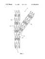
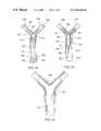
- FIG. 1illustrates a side elevation of a bifurcated stent in accordance with the present invention
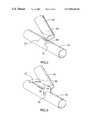
- FIGS. 2-4illustrate a first embodiment of a method for production of a bifurcated stent
- FIG. 5illustrates a second embodiment of a method for production of a bifurcated stent
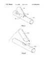
- FIGS. 6 a and 6 billustrate a post-treatment of a bifurcated stent which has been produced according to the methods illustrated in FIGS. 2-5;
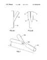
- FIGS. 7 and 8illustrate a third embodiment of a method for production of a bifurcated stent
- FIG. 9illustrates a post-treated bifurcated stent which has been produced according to the method illustrated in FIGS. 7 and 8;
- FIGS. 10 and 11illustrate a fourth embodiment of a method for production of a bifurcated stent
- FIG. 12illustrates a cross-section of a bifurcated body passageway into which the a bifurcated stent produced according to the present method of manufacture is being delivered;
- FIG. 13illustrates a cross-section of a bifurcated body passageway in which the bifurcated stent is positioned in a first, contracted position
- FIG. 14illustrates a cross-section of a bifurcated body passageway in which the bifurcated stent is positioned in a second, expanded position
- FIGS. 15 and 16illustrate a side elevation of another bifurcated stent in accordance with the present invention.
- FIGS. 17-22illustrate various preferred features of the bifurcated stent illustrated in FIGS. 15 and 16.
- Stent 10comprises a proximal end 15 and a distal end 20 .
- Proximal end 15comprises a primary passageway 25 .
- Distal end 20comprises a pair of secondary passageways 30 , 35 .
- Secondary passageways 30 , 35are connected to primary passageway 25 at an intersection point 40 .
- stent 10incorporates the porous surface design illustrated in copending Canadian patent application number 2,134,944, referred to above. As discussed above, this design may be varied to incorporate other designs such as those disclosed in the other Divysio patent applications.
- FIGS. 2-4an embodiment of the present method for production of a bifurcated stent is illustrated.
- the porous surface of the tubular wall of the stentis not illustrated.
- a first stent section 45comprises a cylindrical tube having a bevelled cut 50 made adjacent one end of the cylindrical tube.
- bevelled cut 50may be incorporated into first stent section 45 during or after the production of first stent section 45 .
- first stent section 45having a pre-selected porous design which includes bevelled cut 50 via a computer programmable, high precision laser etching technique.
- a second stent section 55is provided and includes radial cuts 56 , 57 and a longitudinal cut 58 .
- Radial cuts 56 , 57 and longitudinal cuts 58may be produced in second stent section 55 in the manner discussed in the previous paragraph with respect to the production of bevelled cut 50 in first stent section 45 .
- a flap portion 51 of first stent section 45is folded away from bevelled cut 50 .
- a pair of flap 52 , 53are folded away from longitudinal cut 58 to expose an opening 54 .
- First stent section 45is then lowered to cover opening 54 of second stent section 55 .
- Flaps 52 , 53are folded to overlap a portion of first stent section 45 .
- Flap 51is folded to overlap a portion of second stent section 55 .
- the degree of such overlap or juxtapositionis sufficient to:
- the flapsmay be secured to the respective stent sections by any suitable means such as spot welding (e.g. by a laser or other suitable means), loops, clips and the like.
- spot weldinge.g. by a laser or other suitable means
- loopse.g. by a laser or other suitable means
- the preferred method of affixing the flaps to the respective stent sectionis to spot weld them.
- intersection point 40(FIG. 1 —overlapping flaps not illustrated for clarity) of the resulting stent is reinforced by virtue of disposition of the flaps overlapping a portion of the respective stent sections.
- flap 51it may be possible and even desirable to reduce the size of or even eliminate flap 51 . Further, in certain circumstances, it may be possible or ever desirable to trim one or both of flaps 52 , 53 prior to connection of first stent section 45 to second stent section 55 .
- FIG. 5there is illustrated another embodiment of the present method for manufacture of a bifurcated stent.
- flap 51(FIGS. 2 and 3) is simply cut away from first stent section 45 a .
- an oval opening 54 ais cut into second stent section 55 a (i.e. there are no flaps affixed to second stent section 55 a ).
- Stent section 45 ais then lowered on and connected to second stent section 55 a .
- First stent section 45 a and second stent section 55 amay be connected to another in the manner described hereinabove with reference to FIG. 2-4.
- FIG. 6 athere is illustrated the stent produced by the methods illustrated in FIGS. 2-4.
- the adjacent termini of first stent section 45 and section stent section 55are subjected to application of gentle squeezing or other sufficient force in the direction of arrows A to facilitate catheterization of the stent.
- the result of such post-production treatment of the stentis illustrated in FIG. 6 b.
- FIGS. 7 and 8there is illustrated yet another embodiment of the present method for manufacture of a bifurcated stent.
- a pair of first stent sections 45 bare secured or affixed to one another.
- an apex portion 46 b of the resulting constructionis removed exposing an opening 54 b .
- a second stent section 55 bis then connected to opening 54 b provided by the combination of first stent sections 45 b .
- the manner of securing second stent section 55 b to the periphery of opening 54 b created by first stent sections 45 bis not particularly restricted and may be effected as discussed hereinabove.
- first stent sections 45 b and second stent section 55 bare shown in FIGS. 2-4 .
- flapswould be used in the manner discussed hereinabove in respect of FIGS. 2-4 to overlap a portion of the opposite stent section.
- first stent sections 45 bare subjected to application of gentle squeezing or other sufficient force in the direction of arrows B to facilitate catheterization of the stent.
- a first stent section 45 cis provided with an opening 54 c .
- a second stent section 55 cis provided with an opening 56 c .
- Second stent section 55 chas a diameter slightly less than that of first stent section 45 c . The difference in diameter between first stent section 45 c and second stent section 55 c is sufficient to enable coaxial movement of the stent sections with respect to one another with causing damage to either stent section.
- second stent section 55 cis coaxially fed into an end of first stent section 45 c .
- opening 54 c of first stent section 45 cit is pulled through opening 54 c as illustrated by arrow D in FIG. 10 .
- Second stent section 55 cis pulled through opening 54 c until opening 56 c is aligned with opening 54 c —this is illustrated by dashed oval E in FIG. 11 .
- region F (FIG. 11) of the resulting bifurcated stentis “double reinforced” since it contains a coaxial disposition of first stent section 45 c and second stent section 55 c . Accordingly, it is possible and, in some cases even desirable, to modify the design of the respective stent sections in this region so that the overall expansion and relative flexibility/rigidity of the stent in this region is commensurate with that of the remaining portion of the stent (i.e. the secondary passageways which branch off from region F in FIG. 11 ).
- FIGS. 10 and 11illustrates the resultant bifurcated stent having a coaxial, overlapping arrangement of stent sections flush at one end, it will be appreciated by those of skill in the art that the length of first stent section 45 c or second stent section 55 c may be shortened thereby minimizing the size of region F in FIG. 11 .
- bifurcated body passageway 150comprised of a proximal passageway 155 and a pair of distal passageways 160 , 165 .
- bifurcated body passageway 150comprises a Type “D” Bifurcation lesion having characteristic blockages 170 , 175 , 180 .
- Stent 10is delivered to bifurcated body passageway 150 in the following manner. Initially, a pair of guidewires 185 , 190 are inserted into proximal passageway 155 such that guidewire 185 enters distal passageway 160 and guidewire 190 enters distal passageway 165 .
- the manner by which the guidewires are insertedis conventional and within the purview of a person skilled in the art.
- stent 10is positioned in association with a pair of catheters 195 , 200 (for clarity, the interior of stent 10 is not shown).
- Catheter 195has associated with it a balloon 205 .
- Catheter 200has associated with it a balloon 210 .
- Balloons 205 , 210substantially fill primary passageway 25 of stent 10 .
- Balloon 205substantially fills secondary passageway 30 of stent 10 .
- Balloon 210substantially fills secondary passageway 35 of stent 10 .
- the stent/catheter/balloon combinationis delivered through proximal passageway 155 with the aid of guidewires 185 , 190 .
- predisposition of guidewires 185 , 190serves to separate secondary passageways 30 , 35 to be disposed in distal passageways 160 , 165 , respectively.
- stent 10is positioned in place.
- balloons 205 , 210are expanded resulting in implantation of stent 10 in the corresponding interior surfaces of proximal passageway 155 and distal passageways 160 , 165 .
- balloons 205 , 210are collapsed.
- catheters 195 , 200 and guidewires 185 , 190have been removed leaving the implanted stent 10 shown in FIG. 14 .
- blockages 170 , 175 , 180are bulged radially outwardly in combination with the appropriate portions of proximal passageway 155 and distal passageways 160 , 165 resulting in a reduction in the overall blockage in bifurcated body passage 150 .
- implantation of stent 10can be accomplished by various other means.
- the balloon and guidewirewould be design to mimic the bifurcated design of the stent.
- the stentcan be made of a suitable material which will expand when bifurcated body passageway 150 is flushed with a liquid having an elevated temperature (e.g. 150° F.-160° F.).
- stent 10can be designed to expand upon the application of mechanical forces other than those applied by a balloon/catheter. Still further, stent 10 can be designed self-expanding (e.g. by constructing stent from material such as nitinol and the like) to be implanted as described above. In this embodiment, the radially outward force exerted on the stent would be generated within the stent itself.
- FIGS. 15-22there is illustrated another preferred bifurcated stent in accordance with the present invention. As will be apparent to those of skill in the art, the stent illustrated in FIGS. 15-22 shares many of the features of stent 10 illustrated in FIG. 1 .
- FIG. 15is a side elevation of stent 100 without the porous surface illustrated (for clarity).
- FIG. 16is a side elevation of an enlarged portion of stent 100 with the porous surface illustrated.
- Stent 100comprises a proximal end 102 and a distal end 104 .
- Proximal end 102comprises a primary passageway 103 .
- Distal end 104comprises a pair of secondary passageways 105 , 106 .
- Secondary passageways 105 , 106are connected to primary passageway 103 at an intersection point 107 —the nature of intersection point 107 will be further discussed hereinbelow. It is intersection point 107 which distinguishes stent 100 in FIG. 16 from stent 10 in FIG. 1 .
- stent 100incorporates the porous surface design illustrated in copending Canadian patent application number 2,134,944, referred to above. As discussed above, this design may be varied to incorporate other designs such as those disclosed in the other Divysio patent applications.
- manufacture of stent 100will be discussed.
- manufacture of stent 100is similar to the manufacture of stent 10 illustrated in FIGS. 14 and discussed hereinabove.
- the principle difference in the manufacture of stent 100is the use of a modified first stent section 108 .
- First stent section 108is constructed from a substantially cylindrical tube 109 .
- a porous surface 110is disposed on a major portion of cylindrical tube 109 .
- a first connection tab 111 and a second connection tab 112are also disposed on cylindrical tube 109 .
- first section 108comprising porous 110 , first connection tab 111 and second connection tab 112 using computer programmable, high precision laser etching techniques or by other etching techniques in combination with precision jig techniques. This results in an end of porous surface 110 comprising first connection tab 111 , second connection tab 112 and a bevelled edge 113 .
- the product of the cutting techniquesis illustrated in FIG. 18 .
- FIG. 19is an enlarged perspective view of a portion of first connection tab 111 (second connection tab 112 is preferably the same).
- first connection tab 111comprises a stem 114 and a head 115 .
- stem 114 and/or head 115are curved to have a shape complementary to the outer surface of the second section to which first stent section 108 is connected (discussed in more detailed hereinbelow).
- Stem 114 and head 115comprise a plurality of slots 116 disposed therein. Slots 116 may be disposed in stem 114 and head 115 by the use of a computer programmable, high precision laser as described above.
- slots 116are disposed throughout the thickness of stem 114 and head 115 .
- Slots 116may be may have a straight or tapered cross-section. Preferably, slots 116 have a thickness in the range of from about 0.0015 to about 0.004 inches. Head 115 further comprises solid (i.e., slot-free or non-porous) regions 117 , 118 .
- slots 116serve to from a porous surface in first connection tab 111 (second connection tab 112 is preferably the same). While it is preferred to have such a porous surface disposed in the connection tabs, the precise nature of the porosity is not particularly restricted. The provision of a porous surface, particularly at head 115 , facilitates expansion of the connection tab while minimizing or avoiding the occurrence of cracking or distortion.
- first connection tab 111 and second connection tab 112are bent or otherwise moved to be substantially collinear with the periphery of bevelled edge 113 (i.e., as illustrated in FIG. 118 ).
- first stent section 108may be connected to another stent section of a design similar to second stent section 55 discussed hereinabove with reference to FIGS. 2 - 4 —see intersection point 107 in FIG. 16 .
- this embodimentas in the embodiments illustrated in FIGS.
- first connection tab 111 and second connection tab 112may be secured to the second stent section as described above. Specifically, it is particularly preferred to connect solid (i.e., non-porous) regions 117 , 118 to the stent section portion.
- first stent section 108in the production a bifurcated stent.
- connection tabsfacilitates attachment of the respective stent sections to one another (e.g., laser welding is facilitated significantly);
- connection tabsfacilitates bending thereof for connection of the respective stent sections
- slots 116are provided in second connection tab 112 (see FIG. 15 ).
- the slotsallows the slots to function as a solid state valve at the “crotch” of the bifurcated stent thereby providing sealed, reinforcement of the bifurcated stent in this crucial region—this is illustrated in FIG. 20 which depicts tapered openings for slots 116 in the apex of the bend in stem 114 .
- FIG. 21illustrates an alternate embodiment of the embodiment illustrated in FIGS. 15-20.
- second stent section 55otherwise the same as that described hereinabove with reference to FIGS. 14, is adapted to include a landing 119 for receiving a solid (i.e. non-slot or non-porous) connection tab 120 .
- Landing 119may be connected to connection tab 120 as described hereinabove.
- connection tab 121having the entire surface thereof slotted and otherwise porous is connected to landing 119 .
- connection tab 111 and second connection tab 112have been illustrated as being attached to first stent portion 108 , it is possible to have these tabs integral with second stent portion 55 .
- the connection tabsdo not have to integral with either of the stent portions and, instead, can be custom-designed, independent connection tabs which are affixed to both stent portions.
- the connection tabsintegral or independent
Landscapes
- Health & Medical Sciences (AREA)
- Engineering & Computer Science (AREA)
- Biomedical Technology (AREA)
- Cardiology (AREA)
- Oral & Maxillofacial Surgery (AREA)
- Transplantation (AREA)
- Heart & Thoracic Surgery (AREA)
- Vascular Medicine (AREA)
- Life Sciences & Earth Sciences (AREA)
- Animal Behavior & Ethology (AREA)
- General Health & Medical Sciences (AREA)
- Public Health (AREA)
- Veterinary Medicine (AREA)
- Physics & Mathematics (AREA)
- Optics & Photonics (AREA)
- Prostheses (AREA)
- Media Introduction/Drainage Providing Device (AREA)
- Auxiliary Devices For And Details Of Packaging Control (AREA)
- Apparatuses And Processes For Manufacturing Resistors (AREA)
- Branching, Merging, And Special Transfer Between Conveyors (AREA)
- Materials For Medical Uses (AREA)
Abstract
Description
| Type | Characteristic |
| A | Prebranch stenosis not involving the ostium of |
| the side branch; | |
| B | Postbranch stenosis of the parent vessel not |
| involving the origin of the side branch; | |
| C | Stenosis encompassing the side branch but not |
| involving the ostium; | |
| D | Stenosis involving the parent vessel and ostium of |
| the side branch; | |
| E | Stenosis involving the ostium of the side branch only; and |
| F | Stenosis discretely involving the parent vessel and ostium |
| of the side branch. | |
Claims (53)
Applications Claiming Priority (3)
| Application Number | Priority Date | Filing Date | Title |
|---|---|---|---|
| CA2175720 | 1996-05-03 | ||
| CA2175720ACA2175720C (en) | 1996-05-03 | 1996-05-03 | Bifurcated stent and method for the manufacture and delivery of same |
| PCT/CA1997/000294WO1997041803A1 (en) | 1996-05-03 | 1997-05-02 | Bifurcated stent and method for the manufacture of same |
Publications (1)
| Publication Number | Publication Date |
|---|---|
| US6811566B1true US6811566B1 (en) | 2004-11-02 |
Family
ID=4158131
Family Applications (2)
| Application Number | Title | Priority Date | Filing Date |
|---|---|---|---|
| US09/180,146Expired - Fee RelatedUS6811566B1 (en) | 1996-05-03 | 1997-05-02 | Bifurcated stent and method for the manufacture of same |
| US08/850,742Expired - LifetimeUS5906640A (en) | 1994-11-03 | 1997-05-02 | Bifurcated stent and method for the manufacture and delivery of same |
Family Applications After (1)
| Application Number | Title | Priority Date | Filing Date |
|---|---|---|---|
| US08/850,742Expired - LifetimeUS5906640A (en) | 1994-11-03 | 1997-05-02 | Bifurcated stent and method for the manufacture and delivery of same |
Country Status (10)
| Country | Link |
|---|---|
| US (2) | US6811566B1 (en) |
| EP (1) | EP0959811B1 (en) |
| JP (1) | JP4659159B2 (en) |
| AT (1) | ATE270860T1 (en) |
| AU (1) | AU2377397A (en) |
| CA (2) | CA2175720C (en) |
| DE (1) | DE69729886T2 (en) |
| ID (1) | ID16864A (en) |
| MY (1) | MY124237A (en) |
| WO (1) | WO1997041803A1 (en) |
Cited By (75)
| Publication number | Priority date | Publication date | Assignee | Title |
|---|---|---|---|---|
| US20040267352A1 (en)* | 1999-01-13 | 2004-12-30 | Davidson Charles J. | Stent with protruding branch portion for bifurcated vessels |
| US20060036315A1 (en)* | 2001-09-24 | 2006-02-16 | Advanced Stent Technologies, Inc. | Stent with protruding branch portion for bifurcated vessels |
| US20060136046A1 (en)* | 2004-12-17 | 2006-06-22 | William A. Cook Australia Pty. Ltd. | Stented side branch graft |
| US20060161245A1 (en)* | 2001-11-07 | 2006-07-20 | Ronald Rakos | Interlocking endoluminal device |
| US20060184228A1 (en)* | 2005-02-17 | 2006-08-17 | Khoury Michael D | Vascular endograft |
| US20060287704A1 (en)* | 2005-06-01 | 2006-12-21 | William A. Cook Australia Pty. Ltd. | Iliac artery stent graft |
| US20070050016A1 (en)* | 2005-08-29 | 2007-03-01 | Boston Scientific Scimed, Inc. | Stent with expanding side branch geometry |
| US20070055350A1 (en)* | 2005-09-02 | 2007-03-08 | Medtronic Vascular, Inc. | Modular branch vessel stent-graft assembly |
| US20070055356A1 (en)* | 2005-09-08 | 2007-03-08 | Boston Scientific Scimed, Inc. | Inflatable bifurcation stent |
| US20070112419A1 (en)* | 2005-11-14 | 2007-05-17 | Boston Scientific Scimed, Inc. | Stent with spiral side-branch |
| US20070143721A1 (en)* | 2004-11-08 | 2007-06-21 | International Business Machines Corporation | System and method for plasma induced modification and improvement of critical dimension uniformity |
| US20070142904A1 (en)* | 2005-12-20 | 2007-06-21 | Boston Scientific Scimed, Inc. | Bifurcated stent with multiple locations for side branch access |
| US20070208415A1 (en)* | 2006-03-06 | 2007-09-06 | Kevin Grotheim | Bifurcated stent with controlled drug delivery |
| US20070225798A1 (en)* | 2006-03-23 | 2007-09-27 | Daniel Gregorich | Side branch stent |
| US20070239261A1 (en)* | 2006-04-07 | 2007-10-11 | Arani Bose | Aneurysm occlusion system and method |
| US20070260304A1 (en)* | 2006-05-02 | 2007-11-08 | Daniel Gregorich | Bifurcated stent with minimally circumferentially projected side branch |
| US20080109066A1 (en)* | 2000-12-11 | 2008-05-08 | Quinn Stephen F | Bifurcated side-access intravascular stent graft |
| US20080177367A1 (en)* | 2007-01-22 | 2008-07-24 | Adam Stys | Treatment device for treating a side branch of a vessel and method for positioning a stent in a side branch |
| US20080177370A1 (en)* | 2007-01-22 | 2008-07-24 | Adam Stys | Device and method for supporting a side branch of a vessel |
| US7537609B2 (en) | 1998-01-14 | 2009-05-26 | Boston Scientific Scimed, Inc. | Extendible stent apparatus |
| US7540881B2 (en) | 2005-12-22 | 2009-06-02 | Boston Scientific Scimed, Inc. | Bifurcation stent pattern |
| US7678142B2 (en) | 1996-11-04 | 2010-03-16 | Boston Scientific Scimed, Inc. | Extendible stent apparatus |
| US20100115637A1 (en)* | 2008-10-27 | 2010-05-06 | Baxter International Inc. | Models of thrombotic thrombocytopenic purpura and methods of use thereof |
| US7758634B2 (en) | 2001-02-26 | 2010-07-20 | Boston Scientific Scimed, Inc. | Bifurcated stent and delivery system |
| US7833266B2 (en) | 2007-11-28 | 2010-11-16 | Boston Scientific Scimed, Inc. | Bifurcated stent with drug wells for specific ostial, carina, and side branch treatment |
| US7833264B2 (en) | 2006-03-06 | 2010-11-16 | Boston Scientific Scimed, Inc. | Bifurcated stent |
| US7842082B2 (en) | 2006-11-16 | 2010-11-30 | Boston Scientific Scimed, Inc. | Bifurcated stent |
| US7850725B2 (en) | 1996-11-04 | 2010-12-14 | Boston Scientific Scimed, Inc. | Extendible stent apparatus |
| US7922758B2 (en) | 2006-06-23 | 2011-04-12 | Boston Scientific Scimed, Inc. | Nesting twisting hinge points in a bifurcated petal geometry |
| US7951191B2 (en) | 2006-10-10 | 2011-05-31 | Boston Scientific Scimed, Inc. | Bifurcated stent with entire circumferential petal |
| US7959668B2 (en) | 2007-01-16 | 2011-06-14 | Boston Scientific Scimed, Inc. | Bifurcated stent |
| US7959669B2 (en) | 2007-09-12 | 2011-06-14 | Boston Scientific Scimed, Inc. | Bifurcated stent with open ended side branch support |
| US8007528B2 (en) | 2004-03-17 | 2011-08-30 | Boston Scientific Scimed, Inc. | Bifurcated stent |
| US8038706B2 (en) | 2005-09-08 | 2011-10-18 | Boston Scientific Scimed, Inc. | Crown stent assembly |
| US8043366B2 (en) | 2005-09-08 | 2011-10-25 | Boston Scientific Scimed, Inc. | Overlapping stent |
| US8118861B2 (en) | 2007-03-28 | 2012-02-21 | Boston Scientific Scimed, Inc. | Bifurcation stent and balloon assemblies |
| US8206429B2 (en) | 2006-11-02 | 2012-06-26 | Boston Scientific Scimed, Inc. | Adjustable bifurcation catheter incorporating electroactive polymer and methods of making and using the same |
| US8216267B2 (en) | 2006-09-12 | 2012-07-10 | Boston Scientific Scimed, Inc. | Multilayer balloon for bifurcated stent delivery and methods of making and using the same |
| US8221494B2 (en) | 2008-02-22 | 2012-07-17 | Endologix, Inc. | Apparatus and method of placement of a graft or graft system |
| US8257425B2 (en) | 1999-01-13 | 2012-09-04 | Boston Scientific Scimed, Inc. | Stent with protruding branch portion for bifurcated vessels |
| US8277501B2 (en) | 2007-12-21 | 2012-10-02 | Boston Scientific Scimed, Inc. | Bi-stable bifurcated stent petal geometry |
| US8298278B2 (en) | 2006-03-07 | 2012-10-30 | Boston Scientific Scimed, Inc. | Bifurcated stent with improvement securement |
| US8298280B2 (en) | 2003-08-21 | 2012-10-30 | Boston Scientific Scimed, Inc. | Stent with protruding branch portion for bifurcated vessels |
| US8317855B2 (en) | 2005-05-26 | 2012-11-27 | Boston Scientific Scimed, Inc. | Crimpable and expandable side branch cell |
| US8343211B2 (en) | 2005-12-14 | 2013-01-01 | Boston Scientific Scimed, Inc. | Connectors for bifurcated stent |
| WO2012109382A3 (en)* | 2011-02-08 | 2013-01-03 | Advanced Bifurcation Systems, Inc. | Multi-stent and multi-balloon apparatus for treating bifurcations and methods of use |
| US20130013053A1 (en)* | 2010-03-19 | 2013-01-10 | David Ernest Hartley | Thoracic Stent Graft |
| US8435284B2 (en) | 2005-12-14 | 2013-05-07 | Boston Scientific Scimed, Inc. | Telescoping bifurcated stent |
| US8480728B2 (en) | 2005-05-26 | 2013-07-09 | Boston Scientific Scimed, Inc. | Stent side branch deployment initiation geometry |
| WO2013172938A1 (en)* | 2012-05-14 | 2013-11-21 | C.R. Bard, Inc. | Uniformly expandable stent |
| US8647376B2 (en) | 2007-03-30 | 2014-02-11 | Boston Scientific Scimed, Inc. | Balloon fold design for deployment of bifurcated stent petal architecture |
| US20140094902A1 (en)* | 2005-02-17 | 2014-04-03 | Khoury Medical Devices, Llc | Vascular endograft |
| US8747456B2 (en) | 2007-12-31 | 2014-06-10 | Boston Scientific Scimed, Inc. | Bifurcation stent delivery system and methods |
| US8769796B2 (en) | 2008-09-25 | 2014-07-08 | Advanced Bifurcation Systems, Inc. | Selective stent crimping |
| US8795347B2 (en) | 2008-09-25 | 2014-08-05 | Advanced Bifurcation Systems, Inc. | Methods and systems for treating a bifurcation with provisional side branch stenting |
| US8808347B2 (en) | 2008-09-25 | 2014-08-19 | Advanced Bifurcation Systems, Inc. | Stent alignment during treatment of a bifurcation |
| US8821562B2 (en) | 2008-09-25 | 2014-09-02 | Advanced Bifurcation Systems, Inc. | Partially crimped stent |
| WO2014144708A1 (en) | 2013-03-15 | 2014-09-18 | The Regents Of The University Of California | Peptides having reduced toxicity that stimulate cholesterol efflux |
| US8932340B2 (en) | 2008-05-29 | 2015-01-13 | Boston Scientific Scimed, Inc. | Bifurcated stent and delivery system |
| USD723165S1 (en) | 2013-03-12 | 2015-02-24 | C. R. Bard, Inc. | Stent |
| US8979917B2 (en) | 2008-09-25 | 2015-03-17 | Advanced Bifurcation Systems, Inc. | System and methods for treating a bifurcation |
| CN104640521A (en)* | 2012-08-20 | 2015-05-20 | 哈利德·艾尔-萨阿敦 | bifurcated double balloon catheter system |
| JP2015104572A (en)* | 2013-11-29 | 2015-06-08 | 弘志 岩村 | Pipe |
| US9364356B2 (en) | 2011-02-08 | 2016-06-14 | Advanced Bifurcation System, Inc. | System and methods for treating a bifurcation with a fully crimped stent |
| US9427340B2 (en) | 2004-12-14 | 2016-08-30 | Boston Scientific Scimed, Inc. | Stent with protruding branch portion for bifurcated vessels |
| US9468545B2 (en) | 2014-04-04 | 2016-10-18 | W. L. Gore & Associates, Inc. | Bifurcated graft device |
| US9737424B2 (en) | 2008-09-25 | 2017-08-22 | Advanced Bifurcation Systems, Inc. | Partially crimped stent |
| US10470871B2 (en) | 2001-12-20 | 2019-11-12 | Trivascular, Inc. | Advanced endovascular graft |
| US10603196B2 (en) | 2009-04-28 | 2020-03-31 | Endologix, Inc. | Fenestrated prosthesis |
| US10772719B2 (en)* | 2017-02-14 | 2020-09-15 | Cook Medical Technologies Llc | Method of making a contoured internal limb for a prosthesis and prosthesis with a contoured internal limb |
| US11129737B2 (en) | 2015-06-30 | 2021-09-28 | Endologix Llc | Locking assembly for coupling guidewire to delivery system |
| US11298252B2 (en) | 2008-09-25 | 2022-04-12 | Advanced Bifurcation Systems Inc. | Stent alignment during treatment of a bifurcation |
| US11406518B2 (en) | 2010-11-02 | 2022-08-09 | Endologix Llc | Apparatus and method of placement of a graft or graft system |
| US12076258B2 (en) | 2008-09-25 | 2024-09-03 | Advanced Bifurcation Systems Inc. | Selective stent crimping |
| US12324756B2 (en) | 2008-09-25 | 2025-06-10 | Advanced Bifurcation Systems Inc. | System and methods for treating a bifurcation |
Families Citing this family (203)
| Publication number | Priority date | Publication date | Assignee | Title |
|---|---|---|---|---|
| CA2079417C (en) | 1991-10-28 | 2003-01-07 | Lilip Lau | Expandable stents and method of making same |
| US6039749A (en) | 1994-02-10 | 2000-03-21 | Endovascular Systems, Inc. | Method and apparatus for deploying non-circular stents and graftstent complexes |
| CA2134997C (en)* | 1994-11-03 | 2009-06-02 | Ian M. Penn | Stent |
| US6991614B2 (en) | 1995-11-07 | 2006-01-31 | Boston Scientific Scimed, Inc. | Ureteral stent for improved patient comfort |
| US6017363A (en)* | 1997-09-22 | 2000-01-25 | Cordis Corporation | Bifurcated axially flexible stent |
| US6258116B1 (en)* | 1996-01-26 | 2001-07-10 | Cordis Corporation | Bifurcated axially flexible stent |
| US6796997B1 (en) | 1996-03-05 | 2004-09-28 | Evysio Medical Devices Ulc | Expandable stent |
| CA2192520A1 (en) | 1996-03-05 | 1997-09-05 | Ian M. Penn | Expandable stent and method for delivery of same |
| EP1066804B1 (en) | 1996-03-05 | 2004-07-14 | Evysio Medical Devices Ulc | Expandable stent |
| US6251133B1 (en) | 1996-05-03 | 2001-06-26 | Medinol Ltd. | Bifurcated stent with improved side branch aperture and method of making same |
| UA58485C2 (en) | 1996-05-03 | 2003-08-15 | Медінол Лтд. | Method for manufacture of bifurcated stent (variants) and bifurcated stent (variants) |
| US7641685B2 (en)* | 1996-05-03 | 2010-01-05 | Medinol Ltd. | System and method for delivering a bifurcated stent |
| US6770092B2 (en) | 1996-05-03 | 2004-08-03 | Medinol Ltd. | Method of delivering a bifurcated stent |
| US6440165B1 (en)* | 1996-05-03 | 2002-08-27 | Medinol, Ltd. | Bifurcated stent with improved side branch aperture and method of making same |
| US6007573A (en)* | 1996-09-18 | 1999-12-28 | Microtherapeutics, Inc. | Intracranial stent and method of use |
| US8211167B2 (en) | 1999-12-06 | 2012-07-03 | Boston Scientific Scimed, Inc. | Method of using a catheter with attached flexible side sheath |
| US6692483B2 (en) | 1996-11-04 | 2004-02-17 | Advanced Stent Technologies, Inc. | Catheter with attached flexible side sheath |
| EP1723931B1 (en) | 1996-11-04 | 2012-01-04 | Advanced Stent Technologies, Inc. | Extendible stent apparatus and method for deploying the same |
| US7220275B2 (en) | 1996-11-04 | 2007-05-22 | Advanced Stent Technologies, Inc. | Stent with protruding branch portion for bifurcated vessels |
| US7591846B2 (en)* | 1996-11-04 | 2009-09-22 | Boston Scientific Scimed, Inc. | Methods for deploying stents in bifurcations |
| US6682536B2 (en) | 2000-03-22 | 2004-01-27 | Advanced Stent Technologies, Inc. | Guidewire introducer sheath |
| JP2001503657A (en)* | 1996-11-08 | 2001-03-21 | ハウザー,ラッセル,エイ. | Transcutaneous bypass graft and fixation system |
| US5906759A (en)* | 1996-12-26 | 1999-05-25 | Medinol Ltd. | Stent forming apparatus with stent deforming blades |
| US7959664B2 (en)* | 1996-12-26 | 2011-06-14 | Medinol, Ltd. | Flat process of drug coating for stents |
| US6951572B1 (en) | 1997-02-20 | 2005-10-04 | Endologix, Inc. | Bifurcated vascular graft and method and apparatus for deploying same |
| US6096073A (en)* | 1997-02-25 | 2000-08-01 | Scimed Life Systems, Inc. | Method of deploying a stent at a lesion site located at a bifurcation in a parent vessel |
| GB9703859D0 (en)* | 1997-02-25 | 1997-04-16 | Plante Sylvain | Expandable intravascular stent |
| FR2760351B1 (en)* | 1997-03-04 | 1999-05-28 | Bernard Glatt | HELICAL STENT FORMING DEVICE AND MANUFACTURING METHOD THEREOF |
| US6409755B1 (en)* | 1997-05-29 | 2002-06-25 | Scimed Life Systems, Inc. | Balloon expandable stent with a self-expanding portion |
| US6070589A (en) | 1997-08-01 | 2000-06-06 | Teramed, Inc. | Methods for deploying bypass graft stents |
| US6165195A (en) | 1997-08-13 | 2000-12-26 | Advanced Cardiovascylar Systems, Inc. | Stent and catheter assembly and method for treating bifurcations |
| US6746476B1 (en) | 1997-09-22 | 2004-06-08 | Cordis Corporation | Bifurcated axially flexible stent |
| AU747698B2 (en)* | 1997-09-23 | 2002-05-16 | Design & Performance - Cyprus Limited | Bifurcated stent with flexible side portion |
| US6254627B1 (en) | 1997-09-23 | 2001-07-03 | Diseno Y Desarrollo Medico S.A. De C.V. | Non-thrombogenic stent jacket |
| US6071308A (en) | 1997-10-01 | 2000-06-06 | Boston Scientific Corporation | Flexible metal wire stent |
| CA2318314C (en)* | 1998-01-14 | 2007-11-13 | Advanced Stent Technologies, Inc. | Extendible stent apparatus |
| US6261241B1 (en)* | 1998-03-03 | 2001-07-17 | Senorx, Inc. | Electrosurgical biopsy device and method |
| US6099497A (en)* | 1998-03-05 | 2000-08-08 | Scimed Life Systems, Inc. | Dilatation and stent delivery system for bifurcation lesions |
| US6626938B1 (en) | 2000-11-16 | 2003-09-30 | Cordis Corporation | Stent graft having a pleated graft member |
| US6887268B2 (en) | 1998-03-30 | 2005-05-03 | Cordis Corporation | Extension prosthesis for an arterial repair |
| US6290731B1 (en) | 1998-03-30 | 2001-09-18 | Cordis Corporation | Aortic graft having a precursor gasket for repairing an abdominal aortic aneurysm |
| FR2777771B1 (en) | 1998-04-27 | 2000-08-25 | Microval | TUBULAR AND FLEXIBLE VASCULAR ENDOPROSTHESIS |
| US6261273B1 (en)* | 1998-05-07 | 2001-07-17 | Carlos E. Ruiz | Access system for branched vessels amd methods of use |
| US6168621B1 (en)* | 1998-05-29 | 2001-01-02 | Scimed Life Systems, Inc. | Balloon expandable stent with a self-expanding portion |
| US6740113B2 (en)* | 1998-05-29 | 2004-05-25 | Scimed Life Systems, Inc. | Balloon expandable stent with a self-expanding portion |
| US6066169A (en)* | 1998-06-02 | 2000-05-23 | Ave Connaught | Expandable stent having articulated connecting rods |
| DE69933560T2 (en)* | 1998-06-19 | 2007-08-30 | Endologix, Inc., Irvine | SELF-EXPANDING, CRUSHING, ENOVOVASCULAR PROSTHESIS |
| NZ510187A (en) | 1998-07-31 | 2003-08-29 | Novo Rps Ulc | Small vessel expandable stent and method for production of same |
| US6143002A (en)* | 1998-08-04 | 2000-11-07 | Scimed Life Systems, Inc. | System for delivering stents to bifurcation lesions |
| US6514281B1 (en) | 1998-09-04 | 2003-02-04 | Scimed Life Systems, Inc. | System for delivering bifurcation stents |
| US6193744B1 (en)* | 1998-09-10 | 2001-02-27 | Scimed Life Systems, Inc. | Stent configurations |
| US7662409B2 (en) | 1998-09-25 | 2010-02-16 | Gel-Del Technologies, Inc. | Protein matrix materials, devices and methods of making and using thereof |
| US6187036B1 (en) | 1998-12-11 | 2001-02-13 | Endologix, Inc. | Endoluminal vascular prosthesis |
| US6733523B2 (en) | 1998-12-11 | 2004-05-11 | Endologix, Inc. | Implantable vascular graft |
| US6660030B2 (en) | 1998-12-11 | 2003-12-09 | Endologix, Inc. | Bifurcation graft deployment catheter |
| US6197049B1 (en) | 1999-02-17 | 2001-03-06 | Endologix, Inc. | Articulating bifurcation graft |
| WO2000033769A1 (en)* | 1998-12-11 | 2000-06-15 | Endologix, Inc. | Endoluminal vascular prosthesis |
| US6059824A (en)* | 1998-12-23 | 2000-05-09 | Taheri; Syde A. | Mated main and collateral stent and method for treatment of arterial disease |
| US7655030B2 (en) | 2003-07-18 | 2010-02-02 | Boston Scientific Scimed, Inc. | Catheter balloon systems and methods |
| US6332892B1 (en) | 1999-03-02 | 2001-12-25 | Scimed Life Systems, Inc. | Medical device with one or more helical coils |
| US8034100B2 (en) | 1999-03-11 | 2011-10-11 | Endologix, Inc. | Graft deployment system |
| US6261316B1 (en)* | 1999-03-11 | 2001-07-17 | Endologix, Inc. | Single puncture bifurcation graft deployment system |
| EP1164968A1 (en)* | 1999-03-30 | 2002-01-02 | Angiolink Corporation | Angular vascular stent |
| US6273911B1 (en) | 1999-04-22 | 2001-08-14 | Advanced Cardiovascular Systems, Inc. | Variable strength stent |
| US6884258B2 (en) | 1999-06-04 | 2005-04-26 | Advanced Stent Technologies, Inc. | Bifurcation lesion stent delivery using multiple guidewires |
| US6402779B1 (en) | 1999-07-26 | 2002-06-11 | Endomed, Inc. | Balloon-assisted intraluminal stent graft |
| DE19938377A1 (en) | 1999-08-06 | 2001-03-01 | Biotronik Mess & Therapieg | Stent for vascular branching |
| US6183481B1 (en) | 1999-09-22 | 2001-02-06 | Endomed Inc. | Delivery system for self-expanding stents and grafts |
| US6689156B1 (en) | 1999-09-23 | 2004-02-10 | Advanced Stent Technologies, Inc. | Stent range transducers and methods of use |
| US7226475B2 (en)* | 1999-11-09 | 2007-06-05 | Boston Scientific Scimed, Inc. | Stent with variable properties |
| US6679910B1 (en) | 1999-11-12 | 2004-01-20 | Latin American Devices Llc | Intraluminal stent |
| US6254593B1 (en) | 1999-12-10 | 2001-07-03 | Advanced Cardiovascular Systems, Inc. | Bifurcated stent delivery system having retractable sheath |
| EP1745761A1 (en) | 2000-08-23 | 2007-01-24 | LeMaitre Acquisition LLC | Method of manufacturing custom intravascular devices |
| WO2002030329A2 (en)* | 2000-10-13 | 2002-04-18 | Rex Medical, L.P. | Covered stents with side branch |
| US6942692B2 (en) | 2000-11-16 | 2005-09-13 | Cordis Corporation | Supra-renal prosthesis and renal artery bypass |
| US6843802B1 (en) | 2000-11-16 | 2005-01-18 | Cordis Corporation | Delivery apparatus for a self expanding retractable stent |
| US7229472B2 (en) | 2000-11-16 | 2007-06-12 | Cordis Corporation | Thoracic aneurysm repair prosthesis and system |
| US7267685B2 (en)* | 2000-11-16 | 2007-09-11 | Cordis Corporation | Bilateral extension prosthesis and method of delivery |
| US7314483B2 (en) | 2000-11-16 | 2008-01-01 | Cordis Corp. | Stent graft with branch leg |
| US20010044650A1 (en)* | 2001-01-12 | 2001-11-22 | Simso Eric J. | Stent for in-stent restenosis |
| US6695877B2 (en) | 2001-02-26 | 2004-02-24 | Scimed Life Systems | Bifurcated stent |
| WO2002067816A1 (en)* | 2001-02-26 | 2002-09-06 | Scimed Life Systems, Inc. | Bifurcated stent and delivery system |
| US6719804B2 (en) | 2001-04-02 | 2004-04-13 | Scimed Life Systems, Inc. | Medical stent and related methods |
| US7232460B2 (en)* | 2001-04-25 | 2007-06-19 | Xillus, Inc. | Nanodevices, microdevices and sensors on in-vivo structures and method for the same |
| US8617231B2 (en) | 2001-05-18 | 2013-12-31 | Boston Scientific Scimed, Inc. | Dual guidewire exchange catheter system |
| ES2319621T3 (en)* | 2001-08-23 | 2009-05-11 | Darrell C. Gumm | ROTARY SYSTEM OF IMPLANT OF ENDOVASCULAR PROTESIS FOR ACCSO OF SIDE BRANCH AND PROTECTION. |
| US6620202B2 (en) | 2001-10-16 | 2003-09-16 | Scimed Life Systems, Inc. | Medical stent with variable coil and related methods |
| US6682537B2 (en) | 2001-12-20 | 2004-01-27 | The Cleveland Clinic Foundation | Apparatus and method for capturing a wire in a blood vessel |
| US7014653B2 (en)* | 2001-12-20 | 2006-03-21 | Cleveland Clinic Foundation | Furcated endovascular prosthesis |
| US6641606B2 (en) | 2001-12-20 | 2003-11-04 | Cleveland Clinic Foundation | Delivery system and method for deploying an endovascular prosthesis |
| US7326237B2 (en) | 2002-01-08 | 2008-02-05 | Cordis Corporation | Supra-renal anchoring prosthesis |
| US7029493B2 (en)* | 2002-01-25 | 2006-04-18 | Cordis Corporation | Stent with enhanced crossability |
| US6989024B2 (en) | 2002-02-28 | 2006-01-24 | Counter Clockwise, Inc. | Guidewire loaded stent for delivery through a catheter |
| US8328877B2 (en) | 2002-03-19 | 2012-12-11 | Boston Scientific Scimed, Inc. | Stent retention element and related methods |
| EP1405613B1 (en)* | 2002-10-04 | 2006-03-22 | Sorin Biomedica Cardio S.R.L. | An implant device for treating aneurisms of the abdominal aorta |
| US7326242B2 (en)* | 2002-11-05 | 2008-02-05 | Boston Scientific Scimed, Inc. | Asymmetric bifurcated crown |
| AU2002368483A1 (en) | 2002-12-19 | 2004-07-14 | Invatec S.R.L. | Endolumenal prosthesis |
| US7300460B2 (en)* | 2002-12-31 | 2007-11-27 | Counter Clockwise, Inc. | Bifurcated guidewire and methods of use |
| US7169177B2 (en)* | 2003-01-15 | 2007-01-30 | Boston Scientific Scimed, Inc. | Bifurcated stent |
| US7314480B2 (en)* | 2003-02-27 | 2008-01-01 | Boston Scientific Scimed, Inc. | Rotating balloon expandable sheath bifurcation delivery |
| US7367989B2 (en)* | 2003-02-27 | 2008-05-06 | Scimed Life Systems, Inc. | Rotating balloon expandable sheath bifurcation delivery |
| US7731747B2 (en)* | 2003-04-14 | 2010-06-08 | Tryton Medical, Inc. | Vascular bifurcation prosthesis with multiple thin fronds |
| US7481834B2 (en) | 2003-04-14 | 2009-01-27 | Tryton Medical, Inc. | Stent for placement at luminal os |
| US8109987B2 (en) | 2003-04-14 | 2012-02-07 | Tryton Medical, Inc. | Method of treating a lumenal bifurcation |
| US7972372B2 (en) | 2003-04-14 | 2011-07-05 | Tryton Medical, Inc. | Kit for treating vascular bifurcations |
| US7758630B2 (en)* | 2003-04-14 | 2010-07-20 | Tryton Medical, Inc. | Helical ostium support for treating vascular bifurcations |
| US7717953B2 (en) | 2004-10-13 | 2010-05-18 | Tryton Medical, Inc. | Delivery system for placement of prosthesis at luminal OS |
| US8083791B2 (en) | 2003-04-14 | 2011-12-27 | Tryton Medical, Inc. | Method of treating a lumenal bifurcation |
| US20040215220A1 (en)* | 2003-04-24 | 2004-10-28 | Dolan Mark J. | Anastomotic stent, apparatus and methods of use thereof |
| US20070032852A1 (en)* | 2003-04-25 | 2007-02-08 | Medtronic Vascular, Inc. | Methods and Apparatus for Treatment of Aneurysms Adjacent to Branch Arteries |
| US7438721B2 (en)* | 2003-04-25 | 2008-10-21 | Medtronic Vascular, Inc. | Universal modular stent graft assembly to accommodate flow to collateral branches |
| US7105015B2 (en)* | 2003-06-17 | 2006-09-12 | Medtronic Vascular, Inc. | Method and system for treating an ostium of a side-branch vessel |
| US20050033406A1 (en)* | 2003-07-15 | 2005-02-10 | Barnhart William H. | Branch vessel stent and graft |
| US8784472B2 (en)* | 2003-08-15 | 2014-07-22 | Boston Scientific Scimed, Inc. | Clutch driven stent delivery system |
| US7628806B2 (en)* | 2003-08-20 | 2009-12-08 | Boston Scientific Scimed, Inc. | Stent with improved resistance to migration |
| US8153591B2 (en) | 2003-08-26 | 2012-04-10 | Gel-Del Technologies, Inc. | Protein biomaterials and biocoacervates and methods of making and using thereof |
| ATE392865T1 (en) | 2003-10-10 | 2008-05-15 | Cook William A Australia | STENT IMPLANTS WITH WINDOWS |
| US9278015B2 (en)* | 2003-10-16 | 2016-03-08 | Minvasys | Catheter system for stenting and drug treatment of bifurcated vessels |
| US7641684B2 (en)* | 2003-10-16 | 2010-01-05 | Minvasys, Sa | Catheter system for stenting bifurcated vessels |
| US7344557B2 (en) | 2003-11-12 | 2008-03-18 | Advanced Stent Technologies, Inc. | Catheter balloon systems and methods |
| US7090694B1 (en) | 2003-11-19 | 2006-08-15 | Advanced Cardiovascular Systems, Inc. | Portal design for stent for treating bifurcated vessels |
| EP1691746B1 (en) | 2003-12-08 | 2015-05-27 | Gel-Del Technologies, Inc. | Mucoadhesive drug delivery devices and methods of making and using thereof |
| US7686841B2 (en)* | 2003-12-29 | 2010-03-30 | Boston Scientific Scimed, Inc. | Rotating balloon expandable sheath bifurcation delivery system |
| US7922753B2 (en) | 2004-01-13 | 2011-04-12 | Boston Scientific Scimed, Inc. | Bifurcated stent delivery system |
| US8012192B2 (en)* | 2004-02-18 | 2011-09-06 | Boston Scientific Scimed, Inc. | Multi-stent delivery system |
| US7225518B2 (en)* | 2004-02-23 | 2007-06-05 | Boston Scientific Scimed, Inc. | Apparatus for crimping a stent assembly |
| US7744619B2 (en)* | 2004-02-24 | 2010-06-29 | Boston Scientific Scimed, Inc. | Rotatable catheter assembly |
| US7922740B2 (en) | 2004-02-24 | 2011-04-12 | Boston Scientific Scimed, Inc. | Rotatable catheter assembly |
| US20070250001A1 (en)* | 2004-05-21 | 2007-10-25 | Pierre Hilaire | Guidewire Separator Device and Method of Use |
| CA2758946C (en) | 2004-05-25 | 2014-10-21 | Tyco Healthcare Group Lp | Vascular stenting for aneurysms |
| CA2565106C (en)* | 2004-05-25 | 2013-11-05 | Chestnut Medical Technologies, Inc. | Flexible vascular occluding device |
| US8617234B2 (en) | 2004-05-25 | 2013-12-31 | Covidien Lp | Flexible vascular occluding device |
| US8623067B2 (en) | 2004-05-25 | 2014-01-07 | Covidien Lp | Methods and apparatus for luminal stenting |
| US8267985B2 (en)* | 2005-05-25 | 2012-09-18 | Tyco Healthcare Group Lp | System and method for delivering and deploying an occluding device within a vessel |
| US20060206200A1 (en) | 2004-05-25 | 2006-09-14 | Chestnut Medical Technologies, Inc. | Flexible vascular occluding device |
| US20050273149A1 (en)* | 2004-06-08 | 2005-12-08 | Tran Thomas T | Bifurcated stent delivery system |
| US20060064064A1 (en)* | 2004-09-17 | 2006-03-23 | Jang G D | Two-step/dual-diameter balloon angioplasty catheter for bifurcation and side-branch vascular anatomy |
| AU2005286843B2 (en)* | 2004-09-21 | 2011-07-14 | Cook Incorporated | Side branch stent graft |
| US20080188803A1 (en)* | 2005-02-03 | 2008-08-07 | Jang G David | Triple-profile balloon catheter |
| US7947207B2 (en) | 2005-04-12 | 2011-05-24 | Abbott Cardiovascular Systems Inc. | Method for retaining a vascular stent on a catheter |
| US7763198B2 (en) | 2005-04-12 | 2010-07-27 | Abbott Cardiovascular Systems Inc. | Method for retaining a vascular stent on a catheter |
| AU2005332044B2 (en) | 2005-05-25 | 2012-01-19 | Covidien Lp | System and method for delivering and deploying and occluding device within a vessel |
| US8273101B2 (en) | 2005-05-25 | 2012-09-25 | Tyco Healthcare Group Lp | System and method for delivering and deploying an occluding device within a vessel |
| US20070106375A1 (en)* | 2005-11-07 | 2007-05-10 | Carlos Vonderwalde | Bifurcated stent assembly |
| US20070123970A1 (en)* | 2005-11-29 | 2007-05-31 | Boston Scientific Scimed, Inc. | Bifurcation stent with overlapping crimped struts |
| US20070203563A1 (en)* | 2006-02-13 | 2007-08-30 | Stephen Hebert | System for delivering a stent |
| US8821561B2 (en) | 2006-02-22 | 2014-09-02 | Boston Scientific Scimed, Inc. | Marker arrangement for bifurcation catheter |
| US8152833B2 (en) | 2006-02-22 | 2012-04-10 | Tyco Healthcare Group Lp | Embolic protection systems having radiopaque filter mesh |
| US20070208414A1 (en)* | 2006-03-06 | 2007-09-06 | Shawn Sorenson | Tapered strength rings on a bifurcated stent petal |
| US20070208419A1 (en)* | 2006-03-06 | 2007-09-06 | Boston Scientific Scimed, Inc. | Bifurcation stent with uniform side branch projection |
| US20070208411A1 (en)* | 2006-03-06 | 2007-09-06 | Boston Scientific Scimed, Inc. | Bifurcated stent with surface area gradient |
| US20070270933A1 (en)* | 2006-03-09 | 2007-11-22 | Abbott Laboratories | Stent having contoured proximal end |
| US8167929B2 (en) | 2006-03-09 | 2012-05-01 | Abbott Laboratories | System and method for delivering a stent to a bifurcated vessel |
| US8828077B2 (en) | 2006-03-15 | 2014-09-09 | Medinol Ltd. | Flat process of preparing drug eluting stents |
| US8348991B2 (en)* | 2006-03-29 | 2013-01-08 | Boston Scientific Scimed, Inc. | Stent with overlap and high expansion |
| US8043358B2 (en)* | 2006-03-29 | 2011-10-25 | Boston Scientific Scimed, Inc. | Stent with overlap and high extension |
| US8834554B2 (en) | 2006-08-22 | 2014-09-16 | Abbott Cardiovascular Systems Inc. | Intravascular stent |
| US8882826B2 (en) | 2006-08-22 | 2014-11-11 | Abbott Cardiovascular Systems Inc. | Intravascular stent |
| US20080097578A1 (en)* | 2006-10-20 | 2008-04-24 | Medtronic Vascular, Inc. | Extender Cuff for Branch Vessel |
| US8523931B2 (en) | 2007-01-12 | 2013-09-03 | Endologix, Inc. | Dual concentric guidewire and methods of bifurcated graft deployment |
| DE102007006844B4 (en) | 2007-02-12 | 2014-06-12 | Bioregeneration Gmbh | Elongated hollow body for replacement of a venous blood vessel and method and mold for producing a crystalline cellulose comprising elongated hollow body |
| US20080255654A1 (en)* | 2007-03-22 | 2008-10-16 | Bay Street Medical | System for delivering a stent |
| US9144508B2 (en)* | 2007-07-19 | 2015-09-29 | Back Bay Medical Inc. | Radially expandable stent |
| US8486134B2 (en) | 2007-08-01 | 2013-07-16 | Boston Scientific Scimed, Inc. | Bifurcation treatment system and methods |
| EP2237770A4 (en) | 2007-12-26 | 2011-11-09 | Gel Del Technologies Inc | Biocompatible protein particles, particle devices and methods thereof |
| WO2009096851A1 (en)* | 2008-01-28 | 2009-08-06 | Milux Holding Sa | A drainage device comprising a filter cleaning device |
| US20090240318A1 (en)* | 2008-03-19 | 2009-09-24 | Boston Scientific Scimed, Inc. | Stent expansion column, strut and connector slit design |
| US8236040B2 (en) | 2008-04-11 | 2012-08-07 | Endologix, Inc. | Bifurcated graft deployment systems and methods |
| WO2009140437A1 (en) | 2008-05-13 | 2009-11-19 | Nfocus Neuromedical, Inc. | Braid implant delivery systems |
| US8333003B2 (en)* | 2008-05-19 | 2012-12-18 | Boston Scientific Scimed, Inc. | Bifurcation stent crimping systems and methods |
| US8377108B2 (en) | 2008-06-02 | 2013-02-19 | Boston Scientific Scimed, Inc. | Staggered two balloon bifurcation catheter assembly and methods |
| WO2009149405A1 (en) | 2008-06-05 | 2009-12-10 | Boston Scientific Scimed, Inc. | Balloon bifurcated lumen treatment |
| JP5662310B2 (en) | 2008-06-05 | 2015-01-28 | ボストン サイエンティフィック サイムド,インコーポレイテッドBoston Scientific Scimed,Inc. | Shrinkable branch device and method of manufacturing the same |
| EP2520320B1 (en) | 2008-07-01 | 2016-11-02 | Endologix, Inc. | Catheter system |
| US8133199B2 (en) | 2008-08-27 | 2012-03-13 | Boston Scientific Scimed, Inc. | Electroactive polymer activation system for a medical device |
| US20100121247A1 (en)* | 2008-11-13 | 2010-05-13 | Chen Yang | Dialysis Graft with Thromboses Prevention Arrangement |
| US10016534B2 (en) | 2008-11-17 | 2018-07-10 | Gel-Del Technologies, Inc. | Protein biomaterial and biocoacervate vessel graft systems and methods of making and using thereof |
| US10772717B2 (en) | 2009-05-01 | 2020-09-15 | Endologix, Inc. | Percutaneous method and device to treat dissections |
| JP2012525239A (en) | 2009-05-01 | 2012-10-22 | エンドロジックス、インク | Transcutaneous methods and devices for treating dissociation (priority information and incorporation by reference) |
| US8382818B2 (en) | 2009-07-02 | 2013-02-26 | Tryton Medical, Inc. | Ostium support for treating vascular bifurcations |
| WO2011008989A2 (en) | 2009-07-15 | 2011-01-20 | Endologix, Inc. | Stent graft |
| WO2011017123A2 (en) | 2009-07-27 | 2011-02-10 | Endologix, Inc. | Stent graft |
| US9402754B2 (en) | 2010-05-18 | 2016-08-02 | Abbott Cardiovascular Systems, Inc. | Expandable endoprostheses, systems, and methods for treating a bifurcated lumen |
| US9393100B2 (en) | 2010-11-17 | 2016-07-19 | Endologix, Inc. | Devices and methods to treat vascular dissections |
| EP2642946B1 (en) | 2010-11-24 | 2023-08-16 | Poseidon Medical Inc. | Support for treating vascular bifurcations |
| US8808350B2 (en) | 2011-03-01 | 2014-08-19 | Endologix, Inc. | Catheter system and methods of using same |
| CN103826577B (en)* | 2011-08-19 | 2017-03-22 | 哈利德·艾尔-萨阿敦 | Stent system and deployment device for bifurcated lesions |
| US10500077B2 (en) | 2012-04-26 | 2019-12-10 | Poseidon Medical Inc. | Support for treating vascular bifurcations |
| US9155647B2 (en) | 2012-07-18 | 2015-10-13 | Covidien Lp | Methods and apparatus for luminal stenting |
| KR101231197B1 (en)* | 2012-09-20 | 2013-02-07 | 썬텍 주식회사 | Polymeric stent |
| US9301831B2 (en) | 2012-10-30 | 2016-04-05 | Covidien Lp | Methods for attaining a predetermined porosity of a vascular device |
| US9452070B2 (en) | 2012-10-31 | 2016-09-27 | Covidien Lp | Methods and systems for increasing a density of a region of a vascular device |
| US9943427B2 (en) | 2012-11-06 | 2018-04-17 | Covidien Lp | Shaped occluding devices and methods of using the same |
| US9157174B2 (en) | 2013-02-05 | 2015-10-13 | Covidien Lp | Vascular device for aneurysm treatment and providing blood flow into a perforator vessel |
| US10034784B2 (en)* | 2013-04-17 | 2018-07-31 | Gilbert H. L. Tang | Heart valve and endovascular graft components and method for delivery |
| US20160000985A1 (en)* | 2014-07-02 | 2016-01-07 | Abbott Cardiovascular Systems Inc. | Extravascular devices supporting an arteriovenous fistula |
| US10959826B2 (en) | 2014-10-16 | 2021-03-30 | Cook Medical Technology LLC | Support structure for scalloped grafts |
| US10179057B2 (en)* | 2015-05-28 | 2019-01-15 | George Kramer | Tracheobronchial Y-stents, delivery catheters and delivery apparatus, and methods for delivering bronchial Y-stents |
| US10130465B2 (en)* | 2016-02-23 | 2018-11-20 | Abbott Cardiovascular Systems Inc. | Bifurcated tubular graft for treating tricuspid regurgitation |
| KR101968602B1 (en)* | 2017-04-28 | 2019-04-15 | 주식회사 에스앤지바이오텍 | Drainage catheter |
| WO2021131857A1 (en)* | 2019-12-25 | 2021-07-01 | 川澄化学工業株式会社 | Stent |
| CN113238471B (en)* | 2021-05-20 | 2023-11-17 | 中国科学技术大学 | Rapid preparation method of bifurcated micro-pipeline |
| DE102021132725A1 (en)* | 2021-12-10 | 2023-06-15 | Phenox Gmbh | Implant for the treatment of aneurysms in the area of bifurcations |
Citations (17)
| Publication number | Priority date | Publication date | Assignee | Title |
|---|---|---|---|---|
| US3155095A (en)* | 1961-02-07 | 1964-11-03 | Adolph M Brown | Anastomosis method and means |
| US5195984A (en)* | 1988-10-04 | 1993-03-23 | Expandable Grafts Partnership | Expandable intraluminal graft |
| US5360443A (en)* | 1990-06-11 | 1994-11-01 | Barone Hector D | Aortic graft for repairing an abdominal aortic aneurysm |
| US5423885A (en)* | 1992-01-31 | 1995-06-13 | Advanced Cardiovascular Systems, Inc. | Stent capable of attachment within a body lumen |
| US5607445A (en)* | 1992-06-18 | 1997-03-04 | American Biomed, Inc. | Stent for supporting a blood vessel |
| US5609605A (en)* | 1994-08-25 | 1997-03-11 | Ethicon, Inc. | Combination arterial stent |
| US5643340A (en)* | 1994-10-27 | 1997-07-01 | Nunokawa; Mioko | Synthetic vascular prosthesis |
| US5669924A (en)* | 1995-10-26 | 1997-09-23 | Shaknovich; Alexander | Y-shuttle stent assembly for bifurcating vessels and method of using the same |
| US5676696A (en)* | 1995-02-24 | 1997-10-14 | Intervascular, Inc. | Modular bifurcated intraluminal grafts and methods for delivering and assembling same |
| US5676697A (en)* | 1996-07-29 | 1997-10-14 | Cardiovascular Dynamics, Inc. | Two-piece, bifurcated intraluminal graft for repair of aneurysm |
| US5693086A (en)* | 1994-02-09 | 1997-12-02 | Boston Scientific Technology, Inc. | Apparatus for delivering an endoluminal stent or prosthesis |
| US5728150A (en)* | 1996-07-29 | 1998-03-17 | Cardiovascular Dynamics, Inc. | Expandable microporous prosthesis |
| US5755734A (en)* | 1996-05-03 | 1998-05-26 | Medinol Ltd. | Bifurcated stent and method of making same |
| US5800526A (en)* | 1995-03-17 | 1998-09-01 | Endotex Interventional Systems, Inc. | Multi-anchor stent |
| US5893887A (en)* | 1997-10-14 | 1999-04-13 | Iowa-India Investments Company Limited | Stent for positioning at junction of bifurcated blood vessel and method of making |
| US6086611A (en)* | 1997-09-25 | 2000-07-11 | Ave Connaught | Bifurcated stent |
| US6183509B1 (en)* | 1995-05-04 | 2001-02-06 | Alain Dibie | Endoprosthesis for the treatment of blood-vessel bifurcation stenosis and purpose-built installation device |
Family Cites Families (6)
| Publication number | Priority date | Publication date | Assignee | Title |
|---|---|---|---|---|
| US2479578A (en)* | 1943-09-25 | 1949-08-23 | Babcock & Wilcox Co | Tubular structure |
| SE397769B (en)* | 1974-11-04 | 1977-11-21 | Gambro Ab | INITIATIVE ELEMENTS FOR USE IN VEHICLE SURGERY AND METHODS OF PRODUCING SUCCESSFUL |
| US4994071A (en)* | 1989-05-22 | 1991-02-19 | Cordis Corporation | Bifurcating stent apparatus and method |
| US5639278A (en)* | 1993-10-21 | 1997-06-17 | Corvita Corporation | Expandable supportive bifurcated endoluminal grafts |
| US5653743A (en)* | 1994-09-09 | 1997-08-05 | Martin; Eric C. | Hypogastric artery bifurcation graft and method of implantation |
| US5709713A (en)* | 1995-03-31 | 1998-01-20 | Cardiovascular Concepts, Inc. | Radially expansible vascular prosthesis having reversible and other locking structures |
- 1996
- 1996-05-03CACA2175720Apatent/CA2175720C/ennot_activeExpired - Fee Related
- 1997
- 1997-05-02JPJP53936697Apatent/JP4659159B2/ennot_activeExpired - Fee Related
- 1997-05-02DEDE69729886Tpatent/DE69729886T2/ennot_activeExpired - Lifetime
- 1997-05-02WOPCT/CA1997/000294patent/WO1997041803A1/enactiveIP Right Grant
- 1997-05-02ATAT97919222Tpatent/ATE270860T1/ennot_activeIP Right Cessation
- 1997-05-02EPEP97919222Apatent/EP0959811B1/ennot_activeExpired - Lifetime
- 1997-05-02USUS09/180,146patent/US6811566B1/ennot_activeExpired - Fee Related
- 1997-05-02USUS08/850,742patent/US5906640A/ennot_activeExpired - Lifetime
- 1997-05-02MYMYPI97001911Apatent/MY124237A/enunknown
- 1997-05-02AUAU23773/97Apatent/AU2377397A/ennot_activeAbandoned
- 1997-05-02CACA2253546Apatent/CA2253546C/ennot_activeExpired - Fee Related
- 1997-05-05IDIDP971484Apatent/ID16864A/enunknown
Patent Citations (17)
| Publication number | Priority date | Publication date | Assignee | Title |
|---|---|---|---|---|
| US3155095A (en)* | 1961-02-07 | 1964-11-03 | Adolph M Brown | Anastomosis method and means |
| US5195984A (en)* | 1988-10-04 | 1993-03-23 | Expandable Grafts Partnership | Expandable intraluminal graft |
| US5360443A (en)* | 1990-06-11 | 1994-11-01 | Barone Hector D | Aortic graft for repairing an abdominal aortic aneurysm |
| US5423885A (en)* | 1992-01-31 | 1995-06-13 | Advanced Cardiovascular Systems, Inc. | Stent capable of attachment within a body lumen |
| US5607445A (en)* | 1992-06-18 | 1997-03-04 | American Biomed, Inc. | Stent for supporting a blood vessel |
| US5693086A (en)* | 1994-02-09 | 1997-12-02 | Boston Scientific Technology, Inc. | Apparatus for delivering an endoluminal stent or prosthesis |
| US5609605A (en)* | 1994-08-25 | 1997-03-11 | Ethicon, Inc. | Combination arterial stent |
| US5643340A (en)* | 1994-10-27 | 1997-07-01 | Nunokawa; Mioko | Synthetic vascular prosthesis |
| US5676696A (en)* | 1995-02-24 | 1997-10-14 | Intervascular, Inc. | Modular bifurcated intraluminal grafts and methods for delivering and assembling same |
| US5800526A (en)* | 1995-03-17 | 1998-09-01 | Endotex Interventional Systems, Inc. | Multi-anchor stent |
| US6183509B1 (en)* | 1995-05-04 | 2001-02-06 | Alain Dibie | Endoprosthesis for the treatment of blood-vessel bifurcation stenosis and purpose-built installation device |
| US5669924A (en)* | 1995-10-26 | 1997-09-23 | Shaknovich; Alexander | Y-shuttle stent assembly for bifurcating vessels and method of using the same |
| US5755734A (en)* | 1996-05-03 | 1998-05-26 | Medinol Ltd. | Bifurcated stent and method of making same |
| US5676697A (en)* | 1996-07-29 | 1997-10-14 | Cardiovascular Dynamics, Inc. | Two-piece, bifurcated intraluminal graft for repair of aneurysm |
| US5728150A (en)* | 1996-07-29 | 1998-03-17 | Cardiovascular Dynamics, Inc. | Expandable microporous prosthesis |
| US6086611A (en)* | 1997-09-25 | 2000-07-11 | Ave Connaught | Bifurcated stent |
| US5893887A (en)* | 1997-10-14 | 1999-04-13 | Iowa-India Investments Company Limited | Stent for positioning at junction of bifurcated blood vessel and method of making |
Cited By (130)
| Publication number | Priority date | Publication date | Assignee | Title |
|---|---|---|---|---|
| US7678142B2 (en) | 1996-11-04 | 2010-03-16 | Boston Scientific Scimed, Inc. | Extendible stent apparatus |
| US7815675B2 (en) | 1996-11-04 | 2010-10-19 | Boston Scientific Scimed, Inc. | Stent with protruding branch portion for bifurcated vessels |
| US7850725B2 (en) | 1996-11-04 | 2010-12-14 | Boston Scientific Scimed, Inc. | Extendible stent apparatus |
| US7537609B2 (en) | 1998-01-14 | 2009-05-26 | Boston Scientific Scimed, Inc. | Extendible stent apparatus |
| US8241349B2 (en) | 1998-01-14 | 2012-08-14 | Boston Scientific Scimed, Inc. | Extendible stent apparatus |
| US7892279B2 (en) | 1998-01-14 | 2011-02-22 | Boston Scientific Scimed, Inc. | Extendible stent apparatus |
| US8257425B2 (en) | 1999-01-13 | 2012-09-04 | Boston Scientific Scimed, Inc. | Stent with protruding branch portion for bifurcated vessels |
| US20040267352A1 (en)* | 1999-01-13 | 2004-12-30 | Davidson Charles J. | Stent with protruding branch portion for bifurcated vessels |
| US7341598B2 (en) | 1999-01-13 | 2008-03-11 | Boston Scientific Scimed, Inc. | Stent with protruding branch portion for bifurcated vessels |
| US20080109066A1 (en)* | 2000-12-11 | 2008-05-08 | Quinn Stephen F | Bifurcated side-access intravascular stent graft |
| US8556961B2 (en)* | 2000-12-11 | 2013-10-15 | W. L. Gore & Associates, Inc. | Method of deploying a bifurcated side-access intravascular stent graft |
| US7758634B2 (en) | 2001-02-26 | 2010-07-20 | Boston Scientific Scimed, Inc. | Bifurcated stent and delivery system |
| US8425590B2 (en) | 2001-09-24 | 2013-04-23 | Boston Scientific Scimed, Inc. | Stent with protruding branch portion for bifurcated vessels |
| US7951192B2 (en) | 2001-09-24 | 2011-05-31 | Boston Scientific Scimed, Inc. | Stent with protruding branch portion for bifurcated vessels |
| US7578841B2 (en) | 2001-09-24 | 2009-08-25 | Boston Scientific Scimed, Inc. | Stent with protruding branch portion for bifurcated vessels |
| US20060036315A1 (en)* | 2001-09-24 | 2006-02-16 | Advanced Stent Technologies, Inc. | Stent with protruding branch portion for bifurcated vessels |
| US20060161245A1 (en)* | 2001-11-07 | 2006-07-20 | Ronald Rakos | Interlocking endoluminal device |
| US10470871B2 (en) | 2001-12-20 | 2019-11-12 | Trivascular, Inc. | Advanced endovascular graft |
| US11439497B2 (en) | 2001-12-20 | 2022-09-13 | Trivascular, Inc. | Advanced endovascular graft |
| US8298280B2 (en) | 2003-08-21 | 2012-10-30 | Boston Scientific Scimed, Inc. | Stent with protruding branch portion for bifurcated vessels |
| US8007528B2 (en) | 2004-03-17 | 2011-08-30 | Boston Scientific Scimed, Inc. | Bifurcated stent |
| US20070143721A1 (en)* | 2004-11-08 | 2007-06-21 | International Business Machines Corporation | System and method for plasma induced modification and improvement of critical dimension uniformity |
| US9427340B2 (en) | 2004-12-14 | 2016-08-30 | Boston Scientific Scimed, Inc. | Stent with protruding branch portion for bifurcated vessels |
| US8864819B2 (en)* | 2004-12-17 | 2014-10-21 | Cook Medical Technologies Llc | Stented side branch graft |
| US20060136046A1 (en)* | 2004-12-17 | 2006-06-22 | William A. Cook Australia Pty. Ltd. | Stented side branch graft |
| US8808358B2 (en) | 2005-02-17 | 2014-08-19 | Khoury Medical Devices, Llc | Vascular endograft |
| US20060184228A1 (en)* | 2005-02-17 | 2006-08-17 | Khoury Michael D | Vascular endograft |
| US9597209B2 (en)* | 2005-02-17 | 2017-03-21 | Khoury Medical Devices, Llc | Vascular endograft |
| US9861505B2 (en) | 2005-02-17 | 2018-01-09 | Khoury Medical Devices, Llc | Vascular endograft |
| US7828837B2 (en) | 2005-02-17 | 2010-11-09 | Khoury Medical Devices, LLC. | Vascular endograft |
| US20140094902A1 (en)* | 2005-02-17 | 2014-04-03 | Khoury Medical Devices, Llc | Vascular endograft |
| WO2006088905A1 (en)* | 2005-02-17 | 2006-08-24 | Khoury Michael D | Vascular endograft |
| US20060229707A1 (en)* | 2005-02-17 | 2006-10-12 | Khoury Michael D | Vascular endograft |
| US8480728B2 (en) | 2005-05-26 | 2013-07-09 | Boston Scientific Scimed, Inc. | Stent side branch deployment initiation geometry |
| US8317855B2 (en) | 2005-05-26 | 2012-11-27 | Boston Scientific Scimed, Inc. | Crimpable and expandable side branch cell |
| AU2006252495B2 (en)* | 2005-06-01 | 2011-07-07 | Cook Incorporated | Side branch stent graft |
| US7846194B2 (en)* | 2005-06-01 | 2010-12-07 | William A. Cook Australia Pty. Ltd. | Iliac artery stent graft |
| US20060287704A1 (en)* | 2005-06-01 | 2006-12-21 | William A. Cook Australia Pty. Ltd. | Iliac artery stent graft |
| US20070050016A1 (en)* | 2005-08-29 | 2007-03-01 | Boston Scientific Scimed, Inc. | Stent with expanding side branch geometry |
| US7955374B2 (en)* | 2005-09-02 | 2011-06-07 | Medtronic Vascular, Inc. | Modular branch vessel stent-graft assembly |
| US20070055350A1 (en)* | 2005-09-02 | 2007-03-08 | Medtronic Vascular, Inc. | Modular branch vessel stent-graft assembly |
| US8043366B2 (en) | 2005-09-08 | 2011-10-25 | Boston Scientific Scimed, Inc. | Overlapping stent |
| US8038706B2 (en) | 2005-09-08 | 2011-10-18 | Boston Scientific Scimed, Inc. | Crown stent assembly |
| US20070055356A1 (en)* | 2005-09-08 | 2007-03-08 | Boston Scientific Scimed, Inc. | Inflatable bifurcation stent |
| US7731741B2 (en) | 2005-09-08 | 2010-06-08 | Boston Scientific Scimed, Inc. | Inflatable bifurcation stent |
| US20070112419A1 (en)* | 2005-11-14 | 2007-05-17 | Boston Scientific Scimed, Inc. | Stent with spiral side-branch |
| US7842081B2 (en) | 2005-11-14 | 2010-11-30 | Boston Scientific Scimed, Inc. | Stent with spiral side-branch |
| US8435284B2 (en) | 2005-12-14 | 2013-05-07 | Boston Scientific Scimed, Inc. | Telescoping bifurcated stent |
| US8343211B2 (en) | 2005-12-14 | 2013-01-01 | Boston Scientific Scimed, Inc. | Connectors for bifurcated stent |
| US20070142904A1 (en)* | 2005-12-20 | 2007-06-21 | Boston Scientific Scimed, Inc. | Bifurcated stent with multiple locations for side branch access |
| US7540881B2 (en) | 2005-12-22 | 2009-06-02 | Boston Scientific Scimed, Inc. | Bifurcation stent pattern |
| US8016878B2 (en) | 2005-12-22 | 2011-09-13 | Boston Scientific Scimed, Inc. | Bifurcation stent pattern |
| US7833264B2 (en) | 2006-03-06 | 2010-11-16 | Boston Scientific Scimed, Inc. | Bifurcated stent |
| US20070208415A1 (en)* | 2006-03-06 | 2007-09-06 | Kevin Grotheim | Bifurcated stent with controlled drug delivery |
| US8298278B2 (en) | 2006-03-07 | 2012-10-30 | Boston Scientific Scimed, Inc. | Bifurcated stent with improvement securement |
| US20070225798A1 (en)* | 2006-03-23 | 2007-09-27 | Daniel Gregorich | Side branch stent |
| US20070239261A1 (en)* | 2006-04-07 | 2007-10-11 | Arani Bose | Aneurysm occlusion system and method |
| US20070260304A1 (en)* | 2006-05-02 | 2007-11-08 | Daniel Gregorich | Bifurcated stent with minimally circumferentially projected side branch |
| US7922758B2 (en) | 2006-06-23 | 2011-04-12 | Boston Scientific Scimed, Inc. | Nesting twisting hinge points in a bifurcated petal geometry |
| US8216267B2 (en) | 2006-09-12 | 2012-07-10 | Boston Scientific Scimed, Inc. | Multilayer balloon for bifurcated stent delivery and methods of making and using the same |
| US9492297B2 (en) | 2006-09-12 | 2016-11-15 | Boston Scientific Scimed, Inc. | Multilayer balloon for bifurcated stent delivery and methods of making and using the same |
| US7951191B2 (en) | 2006-10-10 | 2011-05-31 | Boston Scientific Scimed, Inc. | Bifurcated stent with entire circumferential petal |
| US8206429B2 (en) | 2006-11-02 | 2012-06-26 | Boston Scientific Scimed, Inc. | Adjustable bifurcation catheter incorporating electroactive polymer and methods of making and using the same |
| US8556955B2 (en) | 2006-11-02 | 2013-10-15 | Boston Scientific Scimed, Inc. | Adjustable bifurcation catheter incorporating electroactive polymer and methods of makings and using the same |
| US7842082B2 (en) | 2006-11-16 | 2010-11-30 | Boston Scientific Scimed, Inc. | Bifurcated stent |
| US7959668B2 (en) | 2007-01-16 | 2011-06-14 | Boston Scientific Scimed, Inc. | Bifurcated stent |
| US20080177370A1 (en)* | 2007-01-22 | 2008-07-24 | Adam Stys | Device and method for supporting a side branch of a vessel |
| US20080177367A1 (en)* | 2007-01-22 | 2008-07-24 | Adam Stys | Treatment device for treating a side branch of a vessel and method for positioning a stent in a side branch |
| US8118861B2 (en) | 2007-03-28 | 2012-02-21 | Boston Scientific Scimed, Inc. | Bifurcation stent and balloon assemblies |
| US8647376B2 (en) | 2007-03-30 | 2014-02-11 | Boston Scientific Scimed, Inc. | Balloon fold design for deployment of bifurcated stent petal architecture |
| US7959669B2 (en) | 2007-09-12 | 2011-06-14 | Boston Scientific Scimed, Inc. | Bifurcated stent with open ended side branch support |
| US7833266B2 (en) | 2007-11-28 | 2010-11-16 | Boston Scientific Scimed, Inc. | Bifurcated stent with drug wells for specific ostial, carina, and side branch treatment |
| US8277501B2 (en) | 2007-12-21 | 2012-10-02 | Boston Scientific Scimed, Inc. | Bi-stable bifurcated stent petal geometry |
| US8747456B2 (en) | 2007-12-31 | 2014-06-10 | Boston Scientific Scimed, Inc. | Bifurcation stent delivery system and methods |
| US8221494B2 (en) | 2008-02-22 | 2012-07-17 | Endologix, Inc. | Apparatus and method of placement of a graft or graft system |
| US8672989B2 (en) | 2008-02-22 | 2014-03-18 | Endologix, Inc. | Apparatus and method of placement of a graft or graft system |
| US10245166B2 (en) | 2008-02-22 | 2019-04-02 | Endologix, Inc. | Apparatus and method of placement of a graft or graft system |
| US9149381B2 (en) | 2008-02-22 | 2015-10-06 | Endologix, Inc. | Apparatus and method of placement of a graft or graft system |
| US8932340B2 (en) | 2008-05-29 | 2015-01-13 | Boston Scientific Scimed, Inc. | Bifurcated stent and delivery system |
| US8769796B2 (en) | 2008-09-25 | 2014-07-08 | Advanced Bifurcation Systems, Inc. | Selective stent crimping |
| US10219926B2 (en) | 2008-09-25 | 2019-03-05 | Advanced Bifurcation Systems Inc. | Selective stent crimping |
| US12324756B2 (en) | 2008-09-25 | 2025-06-10 | Advanced Bifurcation Systems Inc. | System and methods for treating a bifurcation |
| US8979917B2 (en) | 2008-09-25 | 2015-03-17 | Advanced Bifurcation Systems, Inc. | System and methods for treating a bifurcation |
| US12076258B2 (en) | 2008-09-25 | 2024-09-03 | Advanced Bifurcation Systems Inc. | Selective stent crimping |
| US12042412B2 (en) | 2008-09-25 | 2024-07-23 | Advanced Bifurcation Systems Inc. | Stent alignment during treatment of a bifurcation |
| US11857442B2 (en) | 2008-09-25 | 2024-01-02 | Advanced Bifurcation Systems Inc. | System and methods for treating a bifurcation |
| US11839562B2 (en) | 2008-09-25 | 2023-12-12 | Advanced Bifurcation Systems Inc. | Partially crimped stent |
| US8828071B2 (en) | 2008-09-25 | 2014-09-09 | Advanced Bifurcation Systems, Inc. | Methods and systems for ostial stenting of a bifurcation |
| US11426297B2 (en) | 2008-09-25 | 2022-08-30 | Advanced Bifurcation Systems Inc. | Selective stent crimping |
| US11298252B2 (en) | 2008-09-25 | 2022-04-12 | Advanced Bifurcation Systems Inc. | Stent alignment during treatment of a bifurcation |
| US8821562B2 (en) | 2008-09-25 | 2014-09-02 | Advanced Bifurcation Systems, Inc. | Partially crimped stent |
| US11000392B2 (en) | 2008-09-25 | 2021-05-11 | Advanced Bifurcation Systems Inc. | Partially crimped stent |
| US8808347B2 (en) | 2008-09-25 | 2014-08-19 | Advanced Bifurcation Systems, Inc. | Stent alignment during treatment of a bifurcation |
| US10918506B2 (en) | 2008-09-25 | 2021-02-16 | Advanced Bifurcation Systems Inc. | System and methods for treating a bifurcation |
| US10610391B2 (en) | 2008-09-25 | 2020-04-07 | Advanced Bifurcation Systems Inc. | Stent alignment during treatment of a bifurcation |
| US9724218B2 (en) | 2008-09-25 | 2017-08-08 | Advanced Bifurcation Systems, Inc. | Methods and systems for ostial stenting of a bifurcation |
| US9730821B2 (en) | 2008-09-25 | 2017-08-15 | Advanced Bifurcation Systems, Inc. | Methods and systems for treating a bifurcation with provisional side branch stenting |
| US9737424B2 (en) | 2008-09-25 | 2017-08-22 | Advanced Bifurcation Systems, Inc. | Partially crimped stent |
| US9855158B2 (en) | 2008-09-25 | 2018-01-02 | Advanced Bifurcation Systems, Inc. | Stent alignment during treatment of a bifurcation |
| US8795347B2 (en) | 2008-09-25 | 2014-08-05 | Advanced Bifurcation Systems, Inc. | Methods and systems for treating a bifurcation with provisional side branch stenting |
| US10219927B2 (en) | 2008-09-25 | 2019-03-05 | Advanced Bifurcation Systems Inc. | System and methods for treating a bifurcation |
| US9587249B2 (en) | 2008-10-27 | 2017-03-07 | Baxalta GmbH | Models of thrombotic thrombocytopenic purpura and methods of use thereof |
| EP3495488A1 (en) | 2008-10-27 | 2019-06-12 | Baxalta GmbH | Models of thrombotic thrombocytopenic purpura and methods of use thereof |
| US20100115637A1 (en)* | 2008-10-27 | 2010-05-06 | Baxter International Inc. | Models of thrombotic thrombocytopenic purpura and methods of use thereof |
| US10603196B2 (en) | 2009-04-28 | 2020-03-31 | Endologix, Inc. | Fenestrated prosthesis |
| US9005268B2 (en)* | 2010-03-19 | 2015-04-14 | Cook Medical Technologies Llc | Thoracic stent graft |
| US20130013053A1 (en)* | 2010-03-19 | 2013-01-10 | David Ernest Hartley | Thoracic Stent Graft |
| US11406518B2 (en) | 2010-11-02 | 2022-08-09 | Endologix Llc | Apparatus and method of placement of a graft or graft system |
| US12053400B2 (en) | 2011-02-08 | 2024-08-06 | Advanced Bifurcation Systems Inc. | Multi-stent and multi-balloon apparatus for treating bifurcations and methods of use |
| US11717428B2 (en) | 2011-02-08 | 2023-08-08 | Advanced Bifurcation Systems Inc. | System and methods for treating a bifurcation with a fully crimped stent |
| US12324757B2 (en) | 2011-02-08 | 2025-06-10 | Advanced Bifurcation Systems Inc. | Multi-stent and multi-balloon apparatus for treating bifurcations and methods of use |
| US12263107B2 (en) | 2011-02-08 | 2025-04-01 | Advanced Bifurcation Systems Inc. | System and methods for treating a bifurcation with a fully crimped stent |
| US11000393B2 (en) | 2011-02-08 | 2021-05-11 | Advanced Bifurcation Systems Inc. | System and methods for treating a bifurcation with a fully crimped stent |
| US10285832B2 (en) | 2011-02-08 | 2019-05-14 | Advanced Bifurcation Systems Inc. | System and methods for treating a bifurcation with a fully crimped stent |
| US9364356B2 (en) | 2011-02-08 | 2016-06-14 | Advanced Bifurcation System, Inc. | System and methods for treating a bifurcation with a fully crimped stent |
| US11484424B2 (en) | 2011-02-08 | 2022-11-01 | Advanced Bifurcation Systems Inc. | Multi-stent and multi-balloon apparatus for treating bifurcations and methods of use |
| US10406010B2 (en) | 2011-02-08 | 2019-09-10 | Advanced Bifurcation Systems Inc. | Multi-stent and multi-balloon apparatus for treating bifurcations and methods of use |
| US9254210B2 (en) | 2011-02-08 | 2016-02-09 | Advanced Bifurcation Systems, Inc. | Multi-stent and multi-balloon apparatus for treating bifurcations and methods of use |
| WO2012109382A3 (en)* | 2011-02-08 | 2013-01-03 | Advanced Bifurcation Systems, Inc. | Multi-stent and multi-balloon apparatus for treating bifurcations and methods of use |
| US10588765B2 (en) | 2012-05-14 | 2020-03-17 | C. R. Bard, Inc. | Uniformly expandable stent |
| WO2013172938A1 (en)* | 2012-05-14 | 2013-11-21 | C.R. Bard, Inc. | Uniformly expandable stent |
| US9066825B2 (en) | 2012-05-14 | 2015-06-30 | C.R. Bard, Inc. | Uniformly expandable stent |
| CN104640521A (en)* | 2012-08-20 | 2015-05-20 | 哈利德·艾尔-萨阿敦 | bifurcated double balloon catheter system |
| USD723165S1 (en) | 2013-03-12 | 2015-02-24 | C. R. Bard, Inc. | Stent |
| WO2014144708A1 (en) | 2013-03-15 | 2014-09-18 | The Regents Of The University Of California | Peptides having reduced toxicity that stimulate cholesterol efflux |
| JP2015104572A (en)* | 2013-11-29 | 2015-06-08 | 弘志 岩村 | Pipe |
| US9468545B2 (en) | 2014-04-04 | 2016-10-18 | W. L. Gore & Associates, Inc. | Bifurcated graft device |
| US11129737B2 (en) | 2015-06-30 | 2021-09-28 | Endologix Llc | Locking assembly for coupling guidewire to delivery system |
| US12186215B2 (en) | 2015-06-30 | 2025-01-07 | Endologix Llc | Locking assembly for coupling guidewire to delivery system |
| US10772719B2 (en)* | 2017-02-14 | 2020-09-15 | Cook Medical Technologies Llc | Method of making a contoured internal limb for a prosthesis and prosthesis with a contoured internal limb |
Also Published As
| Publication number | Publication date |
|---|---|
| DE69729886T2 (en) | 2005-08-25 |
| EP0959811B1 (en) | 2004-07-14 |
| CA2253546C (en) | 2011-06-28 |
| ID16864A (en) | 1997-11-20 |
| WO1997041803A1 (en) | 1997-11-13 |
| EP0959811A1 (en) | 1999-12-01 |
| CA2175720A1 (en) | 1997-11-04 |
| CA2175720C (en) | 2011-11-29 |
| DE69729886D1 (en) | 2004-08-19 |
| AU2377397A (en) | 1997-11-26 |
| JP2001501496A (en) | 2001-02-06 |
| MY124237A (en) | 2006-06-30 |
| CA2253546A1 (en) | 1997-11-13 |
| JP4659159B2 (en) | 2011-03-30 |
| ATE270860T1 (en) | 2004-07-15 |
| US5906640A (en) | 1999-05-25 |
Similar Documents
| Publication | Publication Date | Title |
|---|---|---|
| US6811566B1 (en) | Bifurcated stent and method for the manufacture of same | |
| US6033435A (en) | Bifurcated stent and method for the manufacture and delivery of same | |
| US5755771A (en) | Expandable stent and method of delivery of same | |
| US6436133B1 (en) | Expandable graft | |
| JP3215807B2 (en) | Expandable stent | |
| HK1009322B (en) | Expandable stent | |
| EP1342455B1 (en) | Expandable supportive branched endoluminal grafts | |
| US8172893B2 (en) | Expandable stent | |
| CN1221222C (en) | Bifurcated stents with soft side branch segments | |
| US20020133222A1 (en) | Expandable stent having a plurality of interconnected expansion modules | |
| WO2007040655A1 (en) | Tether guided stent side branch | |
| JP2010246987A (en) | Small vessel expandable stent and method for production of same | |
| US7824438B2 (en) | Method for placement of a stent assembly in a bifurcated vessel | |
| US20090259299A1 (en) | Side Branch Stent Having a Proximal Flexible Material Section | |
| US8470017B2 (en) | Balloon for use in placing stents in bifurcated vessels | |
| US9186265B2 (en) | Implantable medical device having a means for positioning it at the precise site of a branching of a blood vessel such as a coronary artery | |
| AU769241B2 (en) | Bifurcated stent and method for the manufacture of same | |
| AU782512B2 (en) | Expandable stent and method for delivery of same | |
| MXPA97003222A (en) | Expandable bifurced stent and method to paramolate mi |
Legal Events
| Date | Code | Title | Description |
|---|---|---|---|
| AS | Assignment | Owner name:DIVYSIO SOLUTIONS LTD., CANADA Free format text:ASSIGNMENT OF ASSIGNORS INTEREST;ASSIGNOR:SHUKOV, GEORGE A.;REEL/FRAME:014935/0693 Effective date:19960903 Owner name:DIVYSIO SOLUTIONS LTD., CANADA Free format text:ASSIGNMENT OF ASSIGNORS INTEREST;ASSIGNORS:PENN, IAN M.;RICCI, DONALD R.;REEL/FRAME:014935/0731 Effective date:19960831 Owner name:DIVYSIO SOLUTIONS (1995) LTD., CANADA Free format text:CHANGE OF NAME;ASSIGNOR:DIVYSIO SOLUTIONS LTD.;REEL/FRAME:014935/0783 Effective date:19970410 Owner name:DIVYSIO SOLUTIONS LTD., CANADA Free format text:ASSIGNMENT OF ASSIGNORS INTEREST;ASSIGNOR:DIVYSIO SOLUTIONS (1995) LTD.;REEL/FRAME:014935/0976 Effective date:19970527 Owner name:DIVYSIO SOLUTIONS LIMITED, CANADA Free format text:CERTIFICATE OF CONTINUANCE OF DIVYSIO SOLUTIONS LTD. AS DIVYSIO SOLUTIONS LIMITED;ASSIGNOR:DIVYSIO SOLUTIONS LTD.;REEL/FRAME:014936/0471 Effective date:19970709 Owner name:DIVYSIO SOLUTIONS ULC, CANADA Free format text:CERTIFICATE OF AMALGAMATION;ASSIGNORS:3008993 NOVA SCOTIA COMPANY;3010076 NOVA SCOTIA LIMITED;DIVYSIO SOLUTIONS LIMITED;REEL/FRAME:014936/0679 Effective date:19970715 Owner name:EVYSIO MEDICAL DEVICES ULC, CANADA Free format text:CERTIFICATE OF AMALGAMATION;ASSIGNORS:DIVYSIO SOLUTIONS ULC;EVYSIO MEDICAL DEVICES INC.;3055838 NOVA SCOTIA COMPANY;REEL/FRAME:014936/0682 Effective date:20010901 | |
| FPAY | Fee payment | Year of fee payment:4 | |
| FPAY | Fee payment | Year of fee payment:8 | |
| REMI | Maintenance fee reminder mailed | ||
| LAPS | Lapse for failure to pay maintenance fees | ||
| STCH | Information on status: patent discontinuation | Free format text:PATENT EXPIRED DUE TO NONPAYMENT OF MAINTENANCE FEES UNDER 37 CFR 1.362 | |
| FP | Lapsed due to failure to pay maintenance fee | Effective date:20161102 |