US6810987B1 - Earbud headset - Google Patents
Earbud headsetDownload PDFInfo
- Publication number
- US6810987B1 US6810987B1US10/313,156US31315602AUS6810987B1US 6810987 B1US6810987 B1US 6810987B1US 31315602 AUS31315602 AUS 31315602AUS 6810987 B1US6810987 B1US 6810987B1
- Authority
- US
- United States
- Prior art keywords
- headset
- ear
- bias member
- speaker housing
- head portion
- Prior art date
- Legal status (The legal status is an assumption and is not a legal conclusion. Google has not performed a legal analysis and makes no representation as to the accuracy of the status listed.)
- Expired - Lifetime, expires
Links
- 230000008878couplingEffects0.000claimsabstractdescription12
- 238000010168coupling processMethods0.000claimsabstractdescription12
- 238000005859coupling reactionMethods0.000claimsabstractdescription12
- 241000746998TragusSpecies0.000claimsdescription8
- 210000000613ear canalAnatomy0.000description10
- 238000004891communicationMethods0.000description5
- 230000005236sound signalEffects0.000description4
- 239000000463materialSubstances0.000description3
- 210000003454tympanic membraneAnatomy0.000description3
- 230000005540biological transmissionEffects0.000description2
- 230000001413cellular effectEffects0.000description2
- 229920001971elastomerPolymers0.000description2
- 230000007246mechanismEffects0.000description2
- 238000000034methodMethods0.000description2
- 238000012986modificationMethods0.000description2
- 230000004048modificationEffects0.000description2
- 230000009471actionEffects0.000description1
- 239000000853adhesiveSubstances0.000description1
- 230000001070adhesive effectEffects0.000description1
- 238000005452bendingMethods0.000description1
- 238000007796conventional methodMethods0.000description1
- 230000003247decreasing effectEffects0.000description1
- 230000001419dependent effectEffects0.000description1
- 238000013461designMethods0.000description1
- 210000000883ear externalAnatomy0.000description1
- 210000005069earsAnatomy0.000description1
- 239000000806elastomerSubstances0.000description1
- 239000006260foamSubstances0.000description1
- 230000007774longtermEffects0.000description1
- 230000007257malfunctionEffects0.000description1
- 238000000465mouldingMethods0.000description1
- 239000012811non-conductive materialSubstances0.000description1
- 239000004033plasticSubstances0.000description1
- 230000002441reversible effectEffects0.000description1
- 230000000087stabilizing effectEffects0.000description1
Images


Classifications
- H—ELECTRICITY
- H04—ELECTRIC COMMUNICATION TECHNIQUE
- H04R—LOUDSPEAKERS, MICROPHONES, GRAMOPHONE PICK-UPS OR LIKE ACOUSTIC ELECTROMECHANICAL TRANSDUCERS; DEAF-AID SETS; PUBLIC ADDRESS SYSTEMS
- H04R1/00—Details of transducers, loudspeakers or microphones
- H04R1/10—Earpieces; Attachments therefor ; Earphones; Monophonic headphones
- H04R1/105—Earpiece supports, e.g. ear hooks
- H—ELECTRICITY
- H04—ELECTRIC COMMUNICATION TECHNIQUE
- H04R—LOUDSPEAKERS, MICROPHONES, GRAMOPHONE PICK-UPS OR LIKE ACOUSTIC ELECTROMECHANICAL TRANSDUCERS; DEAF-AID SETS; PUBLIC ADDRESS SYSTEMS
- H04R1/00—Details of transducers, loudspeakers or microphones
- H04R1/10—Earpieces; Attachments therefor ; Earphones; Monophonic headphones
- H04R1/1016—Earpieces of the intra-aural type
- H—ELECTRICITY
- H04—ELECTRIC COMMUNICATION TECHNIQUE
- H04R—LOUDSPEAKERS, MICROPHONES, GRAMOPHONE PICK-UPS OR LIKE ACOUSTIC ELECTROMECHANICAL TRANSDUCERS; DEAF-AID SETS; PUBLIC ADDRESS SYSTEMS
- H04R2201/00—Details of transducers, loudspeakers or microphones covered by H04R1/00 but not provided for in any of its subgroups
- H04R2201/10—Details of earpieces, attachments therefor, earphones or monophonic headphones covered by H04R1/10 but not provided for in any of its subgroups
- H04R2201/107—Monophonic and stereophonic headphones with microphone for two-way hands free communication
Definitions
- This inventiongenerally relates to headsets containing earphones and, more particularly, to an “in-the-ear” type headset apparatus with improved wearing stability, universal fit, and sound quality.
- Headsetsare gaining in popularity in and out of the workplace as more and more users either have jobs requiring that they spend a substantial amount of time on the telephone or users simply desire to listen to audio or speak on the telephone with their hands free to perform other tasks.
- headsetwhich can incorporate one or two earphones for monaural or stereo listening, is known as an “in-the-ear” type headset or “earbud” headset, which employs earphones that can be disposed in the lower concha area of the ear.
- earphonesthat can be disposed in the lower concha area of the ear.
- Such devicescan be used for delivering radio, stereo, two-way, and/or telephonic-type communications to a user.
- Hands-free headsets which are placed in the earmust adapt to a wide variety of ear shapes and sizes in order to fit a large percentage of users. Comfort, stability, and high sound quality are key elements that must be met in order for a headset to be acceptable to the end user.
- different ear shapes and sizesmake it difficult for a single design to both fit the ear correctly and stabilize the headset. Lack of good coupling to the ear results in unclear transmission of sound from the transducer and inability to block out external noise. Headsets including a microphone coupled by a boom cause additional complexity as these headsets need to support the weight and movement of the boom with just the fit of the earphone in the ear.
- a conventional method and apparatus for making an in-the-ear headset fit a wide variety of ear sizeshas been to offer various accessories that slip over the earphone to provide a larger profile to fill a lower concha area of the user's ear.
- the present inventionprovides an earbud headset that allows for improved comfort, sound quality, and stability on the ear without the need for a headband, ear hook, or other accessories, such as a ring or cushion.
- a thin edge portion in conjunction with a bias memberallows for greater acoustic coupling in front of the ear canal, and since no accessories such as rings or cushions are required, sound may be more clearly transmitted to the ear canal, resulting in improved sound quality.
- an earbud headsetincluding a speaker housing.
- the speaker housingincludes a head portion for contacting a lower concha of a ear, and a thin edge portion that extends from the head portion to interface with a faceplate.
- a bias memberis operably coupled to the speaker housing and is capable of contacting a portion of the upper concha of the ear.
- an earbud headsetincluding a speaker housing that has a center portion with a concave surface.
- a head portionwhich extends from the center portion for contacting a lower concha of a ear, includes a transducer.
- an earbud headsetincluding a speaker housing that has a tail portion for contacting an intertragic notch of the ear.
- a center portionwhich extends from the tail portion, is capable of contacting a portion of a tragus and an anti-tragus of an ear.
- the present inventionallows for universal fit in ears of various sizes while providing enhanced sound quality and positional stability.
- FIG. 1illustrates relevant parts of a typical human ear.
- FIG. 2illustrates a side view of an earbud headset in accordance with an embodiment of the present invention.
- FIGS. 3 and 4illustrate a back view and a front view, respectively, of an earbud headset in accordance with an embodiment of the present invention.
- FIG. 5illustrates an earbud headset including a microphone boom and a microphone pod, disposed in a user's ear, in accordance with an embodiment of the present invention.
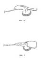
- FIG. 6is a perspective view of an earbud headset in accordance with an embodiment of the present invention.
- FIG. 7is another perspective view of an earbud headset in accordance with an embodiment of the present invention.
- FIG. 8illustrates an earbud headset disposed in a model ear in accordance with an embodiment of the present invention.
- FIG. 1For illustration purposes and to aid in the understanding of the placement of the present invention, a typical human ear is illustrated in FIG. 1 .
- the outer ear, or pinnais an irregularly concave cartilaginous member including a number of eminences and depressions which give each ear a distinct shape and form.
- the helix 29is the curved outer rim of the ear. Below the helix 29 is the antihelix 45 .
- the antihelix 45is a curved prominence which describes a curve around the concha, a deep cavity containing the entry to the ear canal 33 .
- the conchais divided into two parts, the upper concha 43 and the lower concha 41 , by the crux of the helix 31 which curves around the outside of the ear, and extends inwards at about the vertical midpoint of the ear.
- the upper concha 43lies above the crux of the helix 31 and below the antihelix 45 .
- the lower concha 41lies below the crux of the helix 31 and surrounds the entry to the ear canal 33 .
- the conchal wall 47separates the concha from the antihelix 45 .
- In front of the lower concha 41 and projecting backwards from the front of the earis the tragus 35 , a small semicircular prominence.
- Opposite the tragus 35 and separated from it by the deep curvature of the intertragic notch 37is the antitragus 39 .
- the intertragic notch 37is formed between the tragus 35 and the antitragus 39 .
- FIGS. 2, 3 , and 4illustrate a side view, a back view, and a front view, respectively, of an enhanced earbud headset 10 in accordance with an embodiment of the present invention.
- earbud headset 10can be used with an audio source 11 , such as a telephone handset, a cellular phone, a personal computer, a media player, or a communication network.
- an audio source 11such as a telephone handset, a cellular phone, a personal computer, a media player, or a communication network.
- the inventionis not limited to receiving a signal from a specific audio source.
- Earbud headset 10may also be used for either monaural or stereo listening by applying an earbud headset 10 to one or each ear of a user.
- FIG. 2shows, in one embodiment, earbud headset 10 , which includes a speaker housing 19 .
- Speaker housing 19includes a tail portion 14 , a center portion 16 , a head portion 18 , and a thin edge portion 20 that interfaces with a faceplate 21 (FIG. 4 ), each portion of speaker housing 19 being designated by dashed-lines.
- speaker housing 19encases a speaker or an audio transducer 24 , in particular within head portion 18 , in one example. Wires leading from audio source 11 to transducer 24 are also partially housed within speaker housing 19 .
- Speaker housing 19may be formed as an integrated single structure. Portions 14 , 16 , 18 , and 20 are denoted by the dashed-line enclosures for descriptive purposes and accordingly, the interfaces of the different portions may be adjusted as necessary in different embodiments. It should also be understood that not all sections or portions described above are required at once to allow the present invention to function.
- tail portion 14is shaped to taper from an interface with center portion 16 toward a first end 23 .
- Tail portion 14is substantially tubular and hollow for receiving a cable 12 , which encloses the wires leading from audio source 11 to transducer 24 .
- Cable 12is operably coupled to transducer 24 to carry signals, which can be converted to an audio signal by transducer 24 .
- Cable 12is used to protect the wires and may be made from a non-conductive material, as is known in the art. It is noted that cable 12 may be received by other portions of speaker housing 19 in other embodiments of the present invention.
- a cable boot 13can be operably coupled to first end 23 of tail portion 14 .
- cable boot 13surrounds a portion of cable 12 immediately adjacent to first end 23 of tail portion 14 to protect cable 12 from strain typically experienced in this portion of cable 12 due to the bending and pulling of cable 12 that may cause a malfunction. It is noted that cable boot 13 may be coupled to other portions of speaker housing 19 in other embodiments of the present invention.
- center portion 16extends from tail portion 14 and forms a substantially curved conical section increasing in diameter from tail portion 14 toward head portion 18 .
- Center portion 16includes a substantially concave surface 17 , which provides for an ergonomic form to allow headset 10 to securely and comfortably mount on the user's ear.
- concave surface 17allows tail portion 14 and center portion 16 to contact the tragus and anti-tragus and/or the intertragic notch of the user's ear with improved stability and comfort.
- Head portion 18extends from center portion 16 and houses transducer 24 (outline shown by long dashed lines).
- Transducer 24can be any type of electromagnetic, piezoelectric, or electrostatic type of driving element, or a combination thereof, or another form of driving element, for generating sound waves from the output face of the transducer.
- transducer 24receives electric signals from audio signal source 11 via wires in cable 12 .
- the signalsmay be digital or analog in nature.
- Transducer 24converts the electric signal to an audio signal and directs the audio signal toward faceplate 21 (FIG. 4 ).
- transducer 24may receive signals through wireless communication channels, such as by BluetoothTM protocols and hardware, in one example.
- Head portion 18is substantially conical with an increasing diameter extending from center portion 16 toward thin edge portion 20 .
- head portion 18is sized to be as small as the enclosed transducer will allow to maximize fit into the recess of the user's ear.
- the diameter of transducer 24is between about 12 mm and about 14 mm, preferably about 13.6 mm.
- Thin edge portion 20extends from head portion 18 and is shaped to have a substantially constant diameter in one embodiment. In another embodiment, thin edge portion 20 may also have the substantially same diameter as head portion 18 where the two portions 18 and 20 meet. In one embodiment, thin edge portion 20 may be molded as a single structure with head portion 18 . In other embodiments, thin edge portion 20 may include a separate cap that is operably coupled to head portion 18 . Thin edge portion 20 is sized to be as thin as possible to interface with faceplate 21 and accommodate the transmission of sound from transducer 24 . In one example, thin edge portion 20 is formed to have a thickness T (FIG. 2 inset) of less than about 1 mm.
- Thin edge portion 20interfaces with faceplate 21 (FIG. 4 ), which is used to direct sound from transducer 24 toward the user's eardrum, regardless of whether earbud headset 10 is in the right ear or the left ear. It should be understood that the invention is not limited to a specific faceplate and any appropriate faceplate that fits within thin edge portion 20 (and in some cases head portion 18 ) may be used to direct sound from the transducer to the user's eardrum.
- thin edge portion 20allows for enhanced acoustic coupling to deeper areas of the user's ear, in particular the entrance area to the ear canal, to block out external noise while directing sound from the transducer to the eardrum. Excluding external sounds from the ear and providing increased coupling to the entrance to the ear canal enhances the performance of earbud headset 10 in a noisy environment.
- bias member 22is operably attached to speaker housing 19 . It is noted that bias member 22 is coupled to speaker housing 19 along a portion substantially behind and apart from the plane of the surface of faceplate 21 . In one embodiment, bias member 22 is operably coupled to speaker housing 19 along head portion 18 or along center portion 16 . In another embodiment, bias member 22 is operably coupled to speaker housing 19 substantially opposite concave surface 17 .
- Bias member 22allows for a contact area “C” (FIG. 5) between top portion 25 (FIGS. 3 and 4) of bias member 22 and a portion of the user's upper concha, below the antihelix, when the earbud headset is worn. Accordingly, top portion 25 of bias member 22 is substantially set apart from and/or behind a plane of faceplate 21 interfaced with thin edge portion 20 and will make contact with the user's upper concha apart from that plane.
- bias member 22along head portion 18 or center portion 16 allows for a biasing force Z with components along the x and y axes (FIG. 2 ), against the headset where bias member 22 is coupled to speaker housing 19 .
- Axis x and axis yare parallel and perpendicular, respectively, to a surface of faceplate 21 interfaced with thin edge portion 20 .
- biasing force Zis directed toward thin edge portion 20 and faceplate 21 in a direction between the x and y axes.
- biasing forcesare provided against speaker housing 19 behind transducer 24 and toward faceplate 21 with components parallel and perpendicular (i.e., along y and x axes) to faceplate 21 .
- bias member 22in accordance with the present invention, allows for biasing forces substantially apart from and/or behind the plane of faceplate 21 interfaced with thin edge portion 20 .
- biasing forces along the x and y axes toward thin edge portion 20 and faceplate 21provide for enhanced headset stability and acoustic coupling to the ear.
- bias member 22is movably connected to head portion 18 by a movable joint, such as a hinge mechanism.
- bias member 22 and head portion 18are coupled as a single structure, thereby not allowing for any movement between bias member 22 and the speaker housing. It should be understood that bias member 22 may be coupled to head portion 18 by conventional means known in the art, such as by an adhesive or by molding as a single structure with the speaker housing.
- Bias member 22is elongated and flexible in one embodiment, permitting a spring hinge-like action which automatically adjusts bias member 22 to the size and shape of the upper concha, while providing sufficient force to hold speaker housing 19 , in particular head portion 18 and thin edge portion 20 , against the lower concha.
- bias member 22is made of material that is sufficiently rigid to provide both flexibility for, and resistance to, positional deformation, and which allows for comfortable and safe biasing against the user's ear.
- bias member 22can be made from a non-abrasive and flexible material, such as a soft elastomer, foam, plastic material, and the like.
- Bias member 22is also formed into a shape for comfortable and safe biasing against the user's ear, and in particular, the upper concha.
- bias member 22is shaped to curve away from thin edge portion 20 and toward center portion 16 to enhance contact with the upper concha of the user's ear and to provide greater bias force.
- Bias member 22may further have a uniform width or can taper from head portion 18 toward the tip that will contact the upper concha.
- Bias member 22can also taper in the reverse direction from the tip that will contact the upper concha toward head portion 18 .
- the present inventionis not limited to the aforementioned shapes for bias member 22 and any shape or shapes may be used which allow for comfortable, safe, and stabilizing contact with the user's upper concha.
- bias member 22may need to be flexed in order to maintain the contact point against the surface of the upper concha.
- the degree of angular flexureis dependent upon the size and shape of the user's ear, particularly the upper concha, the antihelix, and the crux of the helix.
- the general flexibility and resilience of bias member 22 in combination with the overall shape of the speaker housingadvantageously allow bias member 22 to automatically adjust to the size and shape of the user's upper concha 43 without any additional mechanical devices so as to be universally-fitting while providing stability and comfort.
- FIG. 5illustrates the positioning of earbud headset 10 mounted on a user's ear in accordance with an embodiment of the present invention.
- headset 10When headset 10 is fully mounted on the ear, headset 10 may contact the user's ear in at least three areas to provide effective acoustic coupling with improved stability and comfort. Head portion 18 and thin edge portion 20 may first be placed in the lower concha area to form a first contact area “A”.
- first contact area “A”the thin edge portion allows for greater coupling in front of the ear canal, and since no accessories such as rings or cushions are required, sound may be more clearly transmitted to the ear canal, resulting in improved sound quality.
- a second contact area “B”is formed between curved section 16 and/or tail portion 14 and the tragus and anti-tragus and/or intertragic notch of the user's ear.
- bias member 22is mounted on the ear, at least a third contact area “C” is formed between bias member 22 and a portion of the upper concha of the user's ear.
- the multiple contact areas with the eardistribute weight and pressure such that headset 10 is more stable on the ear, and the required contact force against the concha area of the ear is reduced, which results in enhanced, long-term headset user comfort.
- a microphonemay be positioned in the vicinity of the user's mouth, usually by a tubular extension, voice tube, boom, or in-line pod, for receiving the user's voice and transmitting it over a telecommunications line.
- earbud headset 10may include a microphone 52 and/or a microphone 54 to enable two-way voice communication by the user in accordance with an embodiment of the present invention.
- microphone 52may be attached to a boom 50 , which is operably connected to the speaker housing, in particular to tail portion 14 in one example.
- a movable joint 51such as a swinging mechanism, may couple boom 50 to speaker housing 19 , such that boom 50 may swing back and forth to the user's mouth and lock into a position as desired by the user.
- microphone 54is enclosed in a pod 53 below speaker housing 19 inline with cable 12 .
- Microphone faceplate 55provides a mesh opening on one side of pod 53 to allow the user to transmit voice signals as desired.
- Microphone pod 53may further include volume control and/or a call switch by including a circuit board operably embedded into the pod and operably connected inline with cable 12 to allow for quick access to volume control and/or actuation of the answer/end call function.
- Headset 10may also include a clothing pin 56 for keeping microphone pod 53 close to the user's mouth and/or cable 12 close to the user's body.
- a connector 58operably connects the earbud headset to an audio source 11 (FIG. 2 ), such as a telephone handset, cellular telephone, a media device, or a computer, and a transmitter for sending voice signals from the user.
- an audio source 11such as a telephone handset, cellular telephone, a media device, or a computer
- connector 58is a 2.5 mm plug or a suitable adapter that allows coupling to the audio source device.
- FIGS. 6-7show different perspective views of an enhanced earbud headset 10 in accordance with an embodiment of the present invention.
- FIG. 8shows an enhanced earbud headset 10 mounted in a model ear in accordance with an embodiment of the present invention.
Landscapes
- Health & Medical Sciences (AREA)
- Otolaryngology (AREA)
- Physics & Mathematics (AREA)
- Engineering & Computer Science (AREA)
- Acoustics & Sound (AREA)
- Signal Processing (AREA)
- Headphones And Earphones (AREA)
Abstract
Description
Claims (27)
Priority Applications (1)
| Application Number | Priority Date | Filing Date | Title |
|---|---|---|---|
| US10/313,156US6810987B1 (en) | 2002-12-06 | 2002-12-06 | Earbud headset |
Applications Claiming Priority (1)
| Application Number | Priority Date | Filing Date | Title |
|---|---|---|---|
| US10/313,156US6810987B1 (en) | 2002-12-06 | 2002-12-06 | Earbud headset |
Publications (1)
| Publication Number | Publication Date |
|---|---|
| US6810987B1true US6810987B1 (en) | 2004-11-02 |
Family
ID=33298176
Family Applications (1)
| Application Number | Title | Priority Date | Filing Date |
|---|---|---|---|
| US10/313,156Expired - LifetimeUS6810987B1 (en) | 2002-12-06 | 2002-12-06 | Earbud headset |
Country Status (1)
| Country | Link |
|---|---|
| US (1) | US6810987B1 (en) |
Cited By (61)
| Publication number | Priority date | Publication date | Assignee | Title |
|---|---|---|---|---|
| US20050008180A1 (en)* | 2003-01-30 | 2005-01-13 | Smith Richard C. | Ambidextrous earpiece |
| US20060147079A1 (en)* | 2004-12-30 | 2006-07-06 | Nokia Corporation | Earphone |
| USD533868S1 (en)* | 2005-04-22 | 2006-12-19 | Sony Corporation | Earphone |
| USD533867S1 (en)* | 2005-04-22 | 2006-12-19 | Sony Corporation | Earphone |
| USD535642S1 (en)* | 2005-10-06 | 2007-01-23 | Future Sonics, Inc. | Rounded earphones |
| WO2007027467A3 (en)* | 2005-08-29 | 2007-06-07 | William F Ryann | Wireless earring assembly |
| USD566687S1 (en)* | 2007-01-26 | 2008-04-15 | Helio, Llc | Earbud for a stereo headset |
| USD568291S1 (en)* | 2006-09-11 | 2008-05-06 | Apple Inc. | Ear phone |
| US20080123889A1 (en)* | 2006-11-27 | 2008-05-29 | Caldarola James F | Open fit canal hearing device |
| US20080170740A1 (en)* | 2007-01-05 | 2008-07-17 | Sync1 | Self-contained dual earbud or earphone system and uses thereof |
| US20080188179A1 (en)* | 2007-02-01 | 2008-08-07 | Lite-On Technology Corp. | Bluetooth earphone and ear-hook device thereof |
| US20080264715A1 (en)* | 2007-04-30 | 2008-10-30 | Waihong Leong | Bandless hearing protector and method |
| US20080298626A1 (en)* | 2006-02-14 | 2008-12-04 | Dean Thomas M | Audio earbud carrier |
| USD587677S1 (en)* | 2006-09-11 | 2009-03-03 | Apple Inc. | Ear phone |
| WO2009030229A1 (en)* | 2007-09-04 | 2009-03-12 | Gn Netcom A/S | Earphone device with bi-stable conchal wall stabilizer |
| US20090095566A1 (en)* | 2007-04-30 | 2009-04-16 | Waihong Leong | Bandless hearing protector and method |
| US20090154739A1 (en)* | 2007-12-13 | 2009-06-18 | Samuel Zellner | Systems and methods employing multiple individual wireless earbuds for a common audio source |
| USD598010S1 (en)* | 2007-05-29 | 2009-08-11 | Smk Corporation | Pair of earphones |
| USD599785S1 (en)* | 2007-05-29 | 2009-09-08 | Smk Corporation | Earphone |
| US20100000054A1 (en)* | 2008-07-01 | 2010-01-07 | Roser Michael G | Wireless earbud safety loop |
| US20100054518A1 (en)* | 2008-09-04 | 2010-03-04 | Alexander Goldin | Head mounted voice communication device with motion control |
| DE102008047520A1 (en)* | 2008-09-16 | 2010-04-15 | Sennheiser Electronic Gmbh & Co. Kg | In-ear handset and expansion adapter |
| US20110007929A1 (en)* | 2009-07-08 | 2011-01-13 | Stanley Rabu | Earbuds with electrostatic discharge protection |
| US7986803B1 (en)* | 2007-05-10 | 2011-07-26 | Plantronics, Inc. | Ear bud speaker earphone with retainer tab |
| US20110235818A1 (en)* | 2004-10-19 | 2011-09-29 | Racal Acoustics Limited | Attachment apparatus |
| US20110261988A1 (en)* | 2007-08-08 | 2011-10-27 | Per Kromann | Earphone device with ear canal protrusion |
| USD656481S1 (en)* | 2011-02-01 | 2012-03-27 | VIZIO Inc. | Earbud with curved surfaces |
| EP2352433A4 (en)* | 2008-11-05 | 2012-04-18 | Mckeon Products Inc | Apparatus and method of anchoring an ear piece |
| USD662495S1 (en) | 2008-09-05 | 2012-06-26 | Apple Inc. | Earphone |
| US8401218B2 (en) | 2010-07-29 | 2013-03-19 | Microsoft Corporation | Adjustable earphone and earphone set |
| US8442244B1 (en) | 2009-08-22 | 2013-05-14 | Marshall Long, Jr. | Surround sound system |
| US8477978B2 (en) | 2006-11-27 | 2013-07-02 | Anova Hearing Labs, Inc. | Open fit canal hearing device |
| US8611969B2 (en) | 2004-01-29 | 2013-12-17 | Surefire, Llc | Cable assembly with earpiece |
| US8625834B2 (en) | 2004-09-27 | 2014-01-07 | Surefire, Llc | Ergonomic earpiece and attachments |
| US20140211977A1 (en)* | 2012-11-16 | 2014-07-31 | Judd Armstrong | Over/under dual-fit wearing option earphones |
| US8929582B2 (en) | 2010-08-16 | 2015-01-06 | Bose Corporation | Earpiece positioning and retaining |
| US20150156579A1 (en)* | 2013-12-03 | 2015-06-04 | Auria Llc | Earphone and adapter for an earphone |
| US9161114B2 (en) | 2013-03-22 | 2015-10-13 | Treefrog Developments, Inc. | Earmolds |
| US20150351688A1 (en)* | 2013-01-28 | 2015-12-10 | Valencell, Inc. | Physiological Monitoring Devices Having Sensing Elements Decoupled from Body Motion |
| US9241210B1 (en)* | 2014-08-21 | 2016-01-19 | Skullcandy, Inc. | Mass ports for tuning driver frequency response |
| US9398365B2 (en) | 2013-03-22 | 2016-07-19 | Otter Products, Llc | Earphone assembly |
| US9398364B2 (en) | 2011-07-28 | 2016-07-19 | Bose Corporation | Earpiece passive noise attenuating |
| US9438984B1 (en) | 2005-08-29 | 2016-09-06 | William F. Ryann | Wearable electronic pieces and organizer |
| US20160337746A1 (en)* | 2015-05-15 | 2016-11-17 | Zound Industries International Ab | Audio listening arrangement |
| USD789330S1 (en)* | 2016-03-07 | 2017-06-13 | Chris J. Katopis | Earbud |
| USD789910S1 (en)* | 2016-03-13 | 2017-06-20 | Chris J. Katopis | Earbud |
| USD797079S1 (en) | 2015-10-20 | 2017-09-12 | Phazon Inc. | Wireless earbud |
| EP3324644A3 (en)* | 2016-11-17 | 2018-07-25 | Oticon A/s | A wireless hearing device with stabilizing guide unit between tragus and antitragus |
| US10045107B2 (en) | 2015-07-21 | 2018-08-07 | Harman International Industries, Incorporated | Eartip that conforms to a user's ear canal |
| US10154331B2 (en) | 2015-02-10 | 2018-12-11 | Phazon Inc. | Wireless earbud |
| USD839243S1 (en) | 2017-09-22 | 2019-01-29 | Surefire, Llc | Earpiece |
| US10257604B2 (en) | 2015-05-15 | 2019-04-09 | Zound Industries International Ab | Headset with ear support |
| US10257628B2 (en) | 2006-11-27 | 2019-04-09 | Anova Hearing Labs, Inc. | Open fit canal hearing device |
| US10375464B2 (en)* | 2016-05-14 | 2019-08-06 | Qingdao GoerTeck Technology Co., Ltd. | Adjustable head-mounted structure |
| US10587947B2 (en) | 2017-02-21 | 2020-03-10 | Plantronics, Inc. | Ear tip with anti-tragus stabilizer |
| JPWO2019058523A1 (en)* | 2017-09-22 | 2020-09-24 | 東京音響株式会社 | Speaker device |
| CN111836151A (en)* | 2019-04-23 | 2020-10-27 | 赛蒂奥雷公司 | Earphone set |
| US20210105553A1 (en)* | 2015-09-16 | 2021-04-08 | Apple Inc. | Earbuds |
| CN113613115A (en)* | 2020-06-10 | 2021-11-05 | 深圳市冠旭电子股份有限公司 | In-ear earphone |
| US20240236544A9 (en)* | 2021-02-27 | 2024-07-11 | Huawei Technologies Co., Ltd. | Headset, headset assembly, and related method |
| US20250184650A1 (en)* | 2023-12-05 | 2025-06-05 | Stealth Labs Inc. | Secure and/or comfortable retention of an earbud through a retainer contacting the concha of the ear |
Citations (10)
| Publication number | Priority date | Publication date | Assignee | Title |
|---|---|---|---|---|
| US1668910A (en)* | 1925-09-26 | 1928-05-08 | Western Electric Co | Adjustable earpiece for audiphones |
| US1893143A (en)* | 1931-10-03 | 1933-01-03 | Dictograph Products Co Inc | Acoustic device |
| US1953437A (en)* | 1932-11-05 | 1934-04-03 | Mayer B A Schier | Auditory insert |
| US3041856A (en)* | 1960-11-02 | 1962-07-03 | Paul M Fay | Ear ornament with three-point resilient support within the tragus, the antitragus and the anti-helix |
| US4420657A (en)* | 1981-10-29 | 1983-12-13 | Acs Communications, Inc. | Adjustable headset |
| US4736435A (en)* | 1980-10-31 | 1988-04-05 | Sony Corporation | Ear piece transducer |
| US5712453A (en) | 1994-04-28 | 1998-01-27 | Plantronics, Inc. | Concha headset stabilizer |
| US5953435A (en) | 1997-05-16 | 1999-09-14 | Hello Direct, Inc. | Intra-concha stabilizer with length adjustable conchal wall hook |
| US6411722B1 (en)* | 2000-05-11 | 2002-06-25 | Dan Wolf | Earphone for an RF transmitting device |
| US20030196850A1 (en)* | 2002-04-18 | 2003-10-23 | Jabra Corporation | Earmold for improved retention of coupled device |
- 2002
- 2002-12-06USUS10/313,156patent/US6810987B1/ennot_activeExpired - Lifetime
Patent Citations (11)
| Publication number | Priority date | Publication date | Assignee | Title |
|---|---|---|---|---|
| US1668910A (en)* | 1925-09-26 | 1928-05-08 | Western Electric Co | Adjustable earpiece for audiphones |
| US1893143A (en)* | 1931-10-03 | 1933-01-03 | Dictograph Products Co Inc | Acoustic device |
| US1953437A (en)* | 1932-11-05 | 1934-04-03 | Mayer B A Schier | Auditory insert |
| US3041856A (en)* | 1960-11-02 | 1962-07-03 | Paul M Fay | Ear ornament with three-point resilient support within the tragus, the antitragus and the anti-helix |
| US4736435A (en)* | 1980-10-31 | 1988-04-05 | Sony Corporation | Ear piece transducer |
| US4420657A (en)* | 1981-10-29 | 1983-12-13 | Acs Communications, Inc. | Adjustable headset |
| US4420657B1 (en)* | 1981-10-29 | 1988-04-26 | ||
| US5712453A (en) | 1994-04-28 | 1998-01-27 | Plantronics, Inc. | Concha headset stabilizer |
| US5953435A (en) | 1997-05-16 | 1999-09-14 | Hello Direct, Inc. | Intra-concha stabilizer with length adjustable conchal wall hook |
| US6411722B1 (en)* | 2000-05-11 | 2002-06-25 | Dan Wolf | Earphone for an RF transmitting device |
| US20030196850A1 (en)* | 2002-04-18 | 2003-10-23 | Jabra Corporation | Earmold for improved retention of coupled device |
Cited By (107)
| Publication number | Priority date | Publication date | Assignee | Title |
|---|---|---|---|---|
| US7394910B2 (en)* | 2003-01-30 | 2008-07-01 | Surefire, Llc | Ambidextrous earpiece |
| US20050008180A1 (en)* | 2003-01-30 | 2005-01-13 | Smith Richard C. | Ambidextrous earpiece |
| US8611969B2 (en) | 2004-01-29 | 2013-12-17 | Surefire, Llc | Cable assembly with earpiece |
| US9042947B2 (en) | 2004-01-29 | 2015-05-26 | Surefire, Llc | Multiple input acoustic coupler |
| US10440459B2 (en) | 2004-01-29 | 2019-10-08 | Surefire, Llc | Ergonomic earpiece |
| US9479856B2 (en) | 2004-01-29 | 2016-10-25 | Surefire, Llc | Ergonomic earpiece |
| US9560436B2 (en) | 2004-09-27 | 2017-01-31 | Surefire, Llc | Ergonomic earpiece and attachments |
| US8625834B2 (en) | 2004-09-27 | 2014-01-07 | Surefire, Llc | Ergonomic earpiece and attachments |
| US10231048B2 (en) | 2004-09-27 | 2019-03-12 | Surefire, Llc | Ergonomic earpiece with attachment mount |
| US10200778B2 (en) | 2004-09-27 | 2019-02-05 | Surefire, Llc | Earpiece with ergonomic extension |
| US20110235818A1 (en)* | 2004-10-19 | 2011-09-29 | Racal Acoustics Limited | Attachment apparatus |
| US20060147079A1 (en)* | 2004-12-30 | 2006-07-06 | Nokia Corporation | Earphone |
| USD533868S1 (en)* | 2005-04-22 | 2006-12-19 | Sony Corporation | Earphone |
| USD533867S1 (en)* | 2005-04-22 | 2006-12-19 | Sony Corporation | Earphone |
| US10498161B1 (en) | 2005-08-29 | 2019-12-03 | William F. Ryann | Organizer for wearable electronic pieces |
| US9438984B1 (en) | 2005-08-29 | 2016-09-06 | William F. Ryann | Wearable electronic pieces and organizer |
| WO2007027467A3 (en)* | 2005-08-29 | 2007-06-07 | William F Ryann | Wireless earring assembly |
| USD535642S1 (en)* | 2005-10-06 | 2007-01-23 | Future Sonics, Inc. | Rounded earphones |
| US20080298626A1 (en)* | 2006-02-14 | 2008-12-04 | Dean Thomas M | Audio earbud carrier |
| USD589491S1 (en) | 2006-09-11 | 2009-03-31 | Apple Inc. | Ear phone |
| USD587677S1 (en)* | 2006-09-11 | 2009-03-03 | Apple Inc. | Ear phone |
| USD568291S1 (en)* | 2006-09-11 | 2008-05-06 | Apple Inc. | Ear phone |
| US10257628B2 (en) | 2006-11-27 | 2019-04-09 | Anova Hearing Labs, Inc. | Open fit canal hearing device |
| US12160710B2 (en) | 2006-11-27 | 2024-12-03 | Anova Hearing Labs, Inc. | Open fit canal hearing device |
| US8477978B2 (en) | 2006-11-27 | 2013-07-02 | Anova Hearing Labs, Inc. | Open fit canal hearing device |
| US11523233B2 (en) | 2006-11-27 | 2022-12-06 | Anova Hearing Labs, Inc. | Open fit canal hearing device |
| US20080123889A1 (en)* | 2006-11-27 | 2008-05-29 | Caldarola James F | Open fit canal hearing device |
| US7940946B2 (en) | 2006-11-27 | 2011-05-10 | Anova Hearing Labs, Inc. | Open fit canal hearing device |
| US20080170740A1 (en)* | 2007-01-05 | 2008-07-17 | Sync1 | Self-contained dual earbud or earphone system and uses thereof |
| WO2008086279A3 (en)* | 2007-01-05 | 2008-11-13 | Sync1 | Self-contained dual earbud or earphone system and uses thereof |
| USD566687S1 (en)* | 2007-01-26 | 2008-04-15 | Helio, Llc | Earbud for a stereo headset |
| US7974664B2 (en)* | 2007-02-01 | 2011-07-05 | Lite-On Technology Corp. | Bluetooth earphone and ear-hook device thereof |
| US20080188179A1 (en)* | 2007-02-01 | 2008-08-07 | Lite-On Technology Corp. | Bluetooth earphone and ear-hook device thereof |
| US20090095566A1 (en)* | 2007-04-30 | 2009-04-16 | Waihong Leong | Bandless hearing protector and method |
| US20080264715A1 (en)* | 2007-04-30 | 2008-10-30 | Waihong Leong | Bandless hearing protector and method |
| US7841446B2 (en) | 2007-04-30 | 2010-11-30 | Kimberly-Clark Worldwide, Inc. | Bandless hearing protector and method |
| US7708110B2 (en)* | 2007-04-30 | 2010-05-04 | Kimberly-Clark Worldwide, Inc. | Bandless hearing protector and method |
| US7986803B1 (en)* | 2007-05-10 | 2011-07-26 | Plantronics, Inc. | Ear bud speaker earphone with retainer tab |
| USD598010S1 (en)* | 2007-05-29 | 2009-08-11 | Smk Corporation | Pair of earphones |
| USD606049S1 (en)* | 2007-05-29 | 2009-12-15 | Smk Corporation | Earphone |
| USD599785S1 (en)* | 2007-05-29 | 2009-09-08 | Smk Corporation | Earphone |
| US20110261988A1 (en)* | 2007-08-08 | 2011-10-27 | Per Kromann | Earphone device with ear canal protrusion |
| US8406447B2 (en)* | 2007-08-08 | 2013-03-26 | Gn Netcom A/S | Earphone device with ear canal protrusion |
| US8374375B2 (en)* | 2007-09-04 | 2013-02-12 | Gn Netcom A/S | Earphone device with bi-stable conchal wall stabilizer |
| US20110123059A1 (en)* | 2007-09-04 | 2011-05-26 | Zhenfei Hu | Earphone device with bi-stable conchal wall stabilizer |
| WO2009030229A1 (en)* | 2007-09-04 | 2009-03-12 | Gn Netcom A/S | Earphone device with bi-stable conchal wall stabilizer |
| US20090154739A1 (en)* | 2007-12-13 | 2009-06-18 | Samuel Zellner | Systems and methods employing multiple individual wireless earbuds for a common audio source |
| US8180078B2 (en) | 2007-12-13 | 2012-05-15 | At&T Intellectual Property I, Lp | Systems and methods employing multiple individual wireless earbuds for a common audio source |
| US8699732B2 (en) | 2007-12-13 | 2014-04-15 | At&T Intellectual Property I, L.P. | Systems and methods employing multiple individual wireless earbuds for a common audio source |
| US10499183B2 (en) | 2007-12-13 | 2019-12-03 | At&T Intellectual Property I, L.P. | Systems and methods employing multiple individual wireless earbuds for a common audio source |
| EP2303205A4 (en)* | 2008-06-26 | 2014-02-26 | Kimberly Clark Co | Bandless hearing protector and method |
| US20100000054A1 (en)* | 2008-07-01 | 2010-01-07 | Roser Michael G | Wireless earbud safety loop |
| US8186022B2 (en) | 2008-07-01 | 2012-05-29 | Roser Michael G | Wireless earbud safety loop |
| US20100054518A1 (en)* | 2008-09-04 | 2010-03-04 | Alexander Goldin | Head mounted voice communication device with motion control |
| USD662495S1 (en) | 2008-09-05 | 2012-06-26 | Apple Inc. | Earphone |
| DE102008047520A1 (en)* | 2008-09-16 | 2010-04-15 | Sennheiser Electronic Gmbh & Co. Kg | In-ear handset and expansion adapter |
| DE102008047520B4 (en) | 2008-09-16 | 2021-10-14 | Sennheiser Electronic Gmbh & Co. Kg | In-ear headphones and extension adapter |
| US9143855B2 (en) | 2008-09-16 | 2015-09-22 | Sennheiser Electronic Gmbh & Co. Kg | In-ear earpiece and expansion adaptor |
| EP3416404A1 (en) | 2008-09-16 | 2018-12-19 | Sennheiser Electronic GmbH & Co. KG | In-ear earpiece and expansion adapter |
| US8897480B2 (en) | 2008-09-16 | 2014-11-25 | Sennheiser Electronic Gmbh & Co. Kg | In-ear earpiece and expansion adaptor |
| US9294831B2 (en) | 2008-09-16 | 2016-03-22 | Sennheiser Electronic Gmbh & Co. Kg | In-ear earpiece and expansion adaptor |
| EP2352433A4 (en)* | 2008-11-05 | 2012-04-18 | Mckeon Products Inc | Apparatus and method of anchoring an ear piece |
| US8428287B2 (en) | 2009-07-08 | 2013-04-23 | Apple Inc. | Earbuds with electrostatic discharge protection |
| US9369794B2 (en) | 2009-07-08 | 2016-06-14 | Apple Inc. | Earbuds with electrostatic discharge protection |
| US20110007929A1 (en)* | 2009-07-08 | 2011-01-13 | Stanley Rabu | Earbuds with electrostatic discharge protection |
| US8442244B1 (en) | 2009-08-22 | 2013-05-14 | Marshall Long, Jr. | Surround sound system |
| US8401218B2 (en) | 2010-07-29 | 2013-03-19 | Microsoft Corporation | Adjustable earphone and earphone set |
| US8718314B2 (en) | 2010-07-29 | 2014-05-06 | Microsoft Corporation | Adjustable earphone and earphone set |
| US8929582B2 (en) | 2010-08-16 | 2015-01-06 | Bose Corporation | Earpiece positioning and retaining |
| US8989426B2 (en) | 2010-08-16 | 2015-03-24 | Bose Corporation | Earpiece positioning and retaining |
| USD656481S1 (en)* | 2011-02-01 | 2012-03-27 | VIZIO Inc. | Earbud with curved surfaces |
| US9398364B2 (en) | 2011-07-28 | 2016-07-19 | Bose Corporation | Earpiece passive noise attenuating |
| US12389151B2 (en) | 2011-07-28 | 2025-08-12 | Bose Corporation | Earpiece passive noise attenuating |
| US20140211977A1 (en)* | 2012-11-16 | 2014-07-31 | Judd Armstrong | Over/under dual-fit wearing option earphones |
| US20150351688A1 (en)* | 2013-01-28 | 2015-12-10 | Valencell, Inc. | Physiological Monitoring Devices Having Sensing Elements Decoupled from Body Motion |
| US12076126B2 (en) | 2013-01-28 | 2024-09-03 | Yukka Magic Llc | Physiological monitoring devices having sensing elements decoupled from body motion |
| US11684278B2 (en) | 2013-01-28 | 2023-06-27 | Yukka Magic Llc | Physiological monitoring devices having sensing elements decoupled from body motion |
| US11266319B2 (en) | 2013-01-28 | 2022-03-08 | Valencell, Inc. | Physiological monitoring devices having sensing elements decoupled from body motion |
| US10856749B2 (en)* | 2013-01-28 | 2020-12-08 | Valencell, Inc. | Physiological monitoring devices having sensing elements decoupled from body motion |
| US9161114B2 (en) | 2013-03-22 | 2015-10-13 | Treefrog Developments, Inc. | Earmolds |
| US9398365B2 (en) | 2013-03-22 | 2016-07-19 | Otter Products, Llc | Earphone assembly |
| US9380370B2 (en)* | 2013-12-03 | 2016-06-28 | Auria Llc | Earphone and adapter for an earphone |
| US20150156579A1 (en)* | 2013-12-03 | 2015-06-04 | Auria Llc | Earphone and adapter for an earphone |
| US9357291B2 (en)* | 2014-08-21 | 2016-05-31 | Skullcandy, Inc. | Mass ports for tuning frequency responses |
| US9241210B1 (en)* | 2014-08-21 | 2016-01-19 | Skullcandy, Inc. | Mass ports for tuning driver frequency response |
| US10154331B2 (en) | 2015-02-10 | 2018-12-11 | Phazon Inc. | Wireless earbud |
| US10257604B2 (en) | 2015-05-15 | 2019-04-09 | Zound Industries International Ab | Headset with ear support |
| US20160337746A1 (en)* | 2015-05-15 | 2016-11-17 | Zound Industries International Ab | Audio listening arrangement |
| US10149040B2 (en)* | 2015-05-15 | 2018-12-04 | Zound Industries International Ab | Audio listening arrangement |
| US10045107B2 (en) | 2015-07-21 | 2018-08-07 | Harman International Industries, Incorporated | Eartip that conforms to a user's ear canal |
| US12177624B2 (en) | 2015-09-16 | 2024-12-24 | Apple Inc. | Earbuds |
| US11678106B2 (en)* | 2015-09-16 | 2023-06-13 | Apple Inc. | Earbuds |
| US20210105553A1 (en)* | 2015-09-16 | 2021-04-08 | Apple Inc. | Earbuds |
| USD797079S1 (en) | 2015-10-20 | 2017-09-12 | Phazon Inc. | Wireless earbud |
| USD849720S1 (en) | 2015-10-20 | 2019-05-28 | Phazon Inc. | Wireless earbud |
| USD789330S1 (en)* | 2016-03-07 | 2017-06-13 | Chris J. Katopis | Earbud |
| USD789910S1 (en)* | 2016-03-13 | 2017-06-20 | Chris J. Katopis | Earbud |
| US10375464B2 (en)* | 2016-05-14 | 2019-08-06 | Qingdao GoerTeck Technology Co., Ltd. | Adjustable head-mounted structure |
| US10582291B2 (en) | 2016-11-17 | 2020-03-03 | Oticon A/S | Wireless hearing device |
| EP3324644A3 (en)* | 2016-11-17 | 2018-07-25 | Oticon A/s | A wireless hearing device with stabilizing guide unit between tragus and antitragus |
| US10587947B2 (en) | 2017-02-21 | 2020-03-10 | Plantronics, Inc. | Ear tip with anti-tragus stabilizer |
| USD839243S1 (en) | 2017-09-22 | 2019-01-29 | Surefire, Llc | Earpiece |
| JPWO2019058523A1 (en)* | 2017-09-22 | 2020-09-24 | 東京音響株式会社 | Speaker device |
| CN111836151A (en)* | 2019-04-23 | 2020-10-27 | 赛蒂奥雷公司 | Earphone set |
| CN113613115A (en)* | 2020-06-10 | 2021-11-05 | 深圳市冠旭电子股份有限公司 | In-ear earphone |
| US20240236544A9 (en)* | 2021-02-27 | 2024-07-11 | Huawei Technologies Co., Ltd. | Headset, headset assembly, and related method |
| US20250184650A1 (en)* | 2023-12-05 | 2025-06-05 | Stealth Labs Inc. | Secure and/or comfortable retention of an earbud through a retainer contacting the concha of the ear |
Similar Documents
| Publication | Publication Date | Title |
|---|---|---|
| US6810987B1 (en) | Earbud headset | |
| US7123737B2 (en) | Ear clasp headset | |
| US10231048B2 (en) | Ergonomic earpiece with attachment mount | |
| US5414769A (en) | Articulated headset support | |
| US5953435A (en) | Intra-concha stabilizer with length adjustable conchal wall hook | |
| CN101766036B (en) | Audio equipment | |
| US7031485B2 (en) | Ear mounting assembly for electronic component | |
| CN1695401B (en) | Personal Wearable Communication and Speaker System | |
| EP2177050B1 (en) | Earphone device with ear canal protrusion | |
| CN105307066A (en) | Monaural wireless headset | |
| US20070254725A1 (en) | Cellular telephone cable assembly | |
| JP2006526295A (en) | Audio headset | |
| US20060147079A1 (en) | Earphone | |
| JP7452948B2 (en) | sound output device | |
| US20240147115A1 (en) | Open-ear bluetooth earphone | |
| CN218783893U (en) | Open bluetooth headset | |
| US7221771B1 (en) | Over-the-ear headset | |
| EP4070566B1 (en) | Adaptive eartip for true wireless stereo headsets | |
| CN221633928U (en) | An open-ear headphone that is comfortable to wear | |
| CN221283320U (en) | Ear clip type earphone with stable sound quality | |
| WO1999017586A1 (en) | Headset apparatus | |
| WO1996002119A1 (en) | Tri-laterally supported post-auricle communications headset | |
| KR100882020B1 (en) | Cordless headset | |
| CN117098027A (en) | Bone conduction earphone and earphone set | |
| US20160270959A1 (en) | Earpiece |
Legal Events
| Date | Code | Title | Description |
|---|---|---|---|
| AS | Assignment | Owner name:PLANTRONICS, INC., CALIFORNIA Free format text:ASSIGNMENT OF ASSIGNORS INTEREST;ASSIGNOR:DEKALB, FREDERICK P.;REEL/FRAME:013575/0812 Effective date:20021205 | |
| STCF | Information on status: patent grant | Free format text:PATENTED CASE | |
| FPAY | Fee payment | Year of fee payment:4 | |
| REMI | Maintenance fee reminder mailed | ||
| FPAY | Fee payment | Year of fee payment:8 | |
| SULP | Surcharge for late payment | Year of fee payment:7 | |
| FEPP | Fee payment procedure | Free format text:PAYER NUMBER DE-ASSIGNED (ORIGINAL EVENT CODE: RMPN); ENTITY STATUS OF PATENT OWNER: LARGE ENTITY Free format text:PAYOR NUMBER ASSIGNED (ORIGINAL EVENT CODE: ASPN); ENTITY STATUS OF PATENT OWNER: LARGE ENTITY | |
| FPAY | Fee payment | Year of fee payment:12 | |
| AS | Assignment | Owner name:WELLS FARGO BANK, NATIONAL ASSOCIATION, NORTH CAROLINA Free format text:SECURITY AGREEMENT;ASSIGNORS:PLANTRONICS, INC.;POLYCOM, INC.;REEL/FRAME:046491/0915 Effective date:20180702 Owner name:WELLS FARGO BANK, NATIONAL ASSOCIATION, NORTH CARO Free format text:SECURITY AGREEMENT;ASSIGNORS:PLANTRONICS, INC.;POLYCOM, INC.;REEL/FRAME:046491/0915 Effective date:20180702 | |
| AS | Assignment | Owner name:POLYCOM, INC., CALIFORNIA Free format text:RELEASE OF PATENT SECURITY INTERESTS;ASSIGNOR:WELLS FARGO BANK, NATIONAL ASSOCIATION;REEL/FRAME:061356/0366 Effective date:20220829 Owner name:PLANTRONICS, INC., CALIFORNIA Free format text:RELEASE OF PATENT SECURITY INTERESTS;ASSIGNOR:WELLS FARGO BANK, NATIONAL ASSOCIATION;REEL/FRAME:061356/0366 Effective date:20220829 |