US6810235B2 - Method and apparatus for detecting communication network delays - Google Patents
Method and apparatus for detecting communication network delaysDownload PDFInfo
- Publication number
- US6810235B2 US6810235B2US10/382,194US38219403AUS6810235B2US 6810235 B2US6810235 B2US 6810235B2US 38219403 AUS38219403 AUS 38219403AUS 6810235 B2US6810235 B2US 6810235B2
- Authority
- US
- United States
- Prior art keywords
- time
- message
- vehicle
- received
- time difference
- Prior art date
- Legal status (The legal status is an assumption and is not a legal conclusion. Google has not performed a legal analysis and makes no representation as to the accuracy of the status listed.)
- Expired - Lifetime, expires
Links
Images


Classifications
- H—ELECTRICITY
- H04—ELECTRIC COMMUNICATION TECHNIQUE
- H04B—TRANSMISSION
- H04B7/00—Radio transmission systems, i.e. using radiation field
- H04B7/14—Relay systems
- H04B7/15—Active relay systems
- H04B7/185—Space-based or airborne stations; Stations for satellite systems
- H04B7/1853—Satellite systems for providing telephony service to a mobile station, i.e. mobile satellite service
- H04B7/18532—Arrangements for managing transmission, i.e. for transporting data or a signalling message
Definitions
- the ideas presented hereinrelate to the field of data communications. More specifically, to a method and apparatus for determining network latency for delivery of packet-based information.
- wireless communication systemsare well known for transmitting information between, for example, fixed stations and one or more geographically dispersed mobile receivers.
- satellite and/or terrestrial wireless communication systemshave been used in the trucking industry for many years to provide messaging and location information between fleet-owned dispatch centers and their respective tractor-trailer vehicles.
- Such systemsoffer significant benefits to fleet owners because they allow almost instantaneous communications and real-time position information.
- many such systemsprovide remote monitoring of the performance characteristics of each fleet-owned vehicle, such as the average vehicle speed, RPM, idle time, and other characteristics.
- fleet-owned dispatch centerstypically communicate with their respective vehicles through a central station, otherwise known as a hub, network management center (NMC), or network management facility (NMF). Communications between dispatch centers and the central station are often sent over land-based communication systems such as telephone or fiber-optic networks. The central station then forwards information to one or more vehicles via a satellite or terrestrial communication system.
- NMCnetwork management center
- NMFnetwork management facility
- Each vehicle in the communication systemis equipped with a transceiver, otherwise known as a mobile communication terminal (MCT), for communicating message and location information to their respective dispatch centers via the satellite or terrestrial communication system and central station.
- MCTmobile communication terminal
- the MCTtypically also comprises an interface device which displays text messages to one or more vehicle occupants and accepts either voice or text messages to be transmitted to the vehicle's fleet-owned dispatch center.
- the MCTmay further comprise circuitry which allows it to communicate with one or more Electronic Control Units (ECUs) located at various points throughout the vehicle.
- ECUsElectronic Control Units
- Each ECUprovides information relating to the operational performance of the vehicle to the digital computer indicating characteristics including, but not limited to, vehicle speed, engine RPM, and miles traveled.
- the wireless communication system described aboveallows vehicle occupants to easily contact their respective dispatch centers in order to keep fleet personnel apprised of various events throughout a typical delivery cycle. For example, upon arrival at a predetermined pickup destination, a truck driver may contact a dispatch center associated with the vehicle to alert fleet personnel of the time and location of the arrival. Similarly, after the truck has been loaded at the pickup destination, the driver may send a message to the dispatch center indicating the time of departure, the location from where the departure occurred, and a description of the goods that is being transported. Another example where a vehicle operator might transmit a status message to the dispatch center is when an unscheduled stop has been made and/or when the vehicle departs from the unscheduled stop.
- an apparatuscomprises a receiver for receiving a message from a vehicle, said message comprising a time stamp indicating when the message was transmitted.
- a processoris used for determining a time that the message was received, for determining a time difference between the time stamp and the time when the message was received, for comparing the time difference to a predetermined time, for determining a number of messages received having a time difference greater than said predetermined time, and for generating a notification if said number of messages received having a time difference greater than said predetermined time exceeds a predetermined number.
- an interfaceis used for providing the notification to an entity.
- an apparatus for detecting communication network delayscomprises a signal-bearing medium tangibly embodying a program of machine-readable instructions executable by a digital processing apparatus to perform a method for validating a vehicle operator, the method comprising operations of receiving a message from a vehicle, the message comprising a time stamp indicating when the message was transmitted, determining a time that the message was received, determining a time difference between the time stamp and the time when the message was received, comparing the time difference to a predetermined time, determining a number of messages received having a time difference greater than said predetermined time, and generating a notification if said number of messages received having a time difference greater than said predetermined time exceeds a predetermined number.
- a method for detecting communication network delayscomprises receiving a message from a vehicle, said message comprising a time stamp indicating when the message was transmitted, determining a time that the message was received, determining a time difference between the time stamp and the time when the message was received, comparing the time difference to a predetermined time, determining a number of messages received having a time difference greater than said predetermined time, and generating a notification if said number of messages received having a time difference greater than said predetermined time exceeds a predetermined number.
- FIG. 1illustrates a wireless communication system in which the method and apparatus for detecting communication network delays is used
- FIG. 2is a functional block diagram of one embodiment of a mobile communication terminal used in the communication system of FIG. 1;
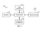
- FIG. 3illustrates a functional block diagram of an apparatus for detecting communication network delays
- Communications between dispatch center 106 and vehicle 100may further be passed to one or more other entities, such as third party center 108 .
- Third party center 108comprises one of any number of interested third parties to communications between central station 102 and vehicle 100 .
- third party center 108could comprise another designated office of central station 102 , a shipper of goods being carried by vehicle 100 , a consignee of goods being carried by vehicle 100 , a wireless network operations center, a governmental unit, a personal computer, a mobile response unit such as an ambulance, fire crew, or other emergency vehicle, and so on.
- dispatch center 106 and third party center 108may also communicate with other entities, for example, communicating wirelessly with remote location 110 as shown in FIG. 1 .
- Remote location 110could comprise any dispatch or other third party mentioned above. Communications among central stations 102 , 106 , 108 , and 110 may be carried out by any known communication techniques, including telephone, internet, dedicated lines, wireless links, and so on.
- the MCT located on vehicle 100transmits and receives communications wirelessly using, in one embodiment, a terrestrial wireless communication system to communicate with central station 102 , such as an analog or a digital cellular telephone system, an RF communication system, or a wireless data communication network, such as a cellular digital packet data (CDPD) network.
- a terrestrial wireless communication systemto communicate with central station 102 , such as an analog or a digital cellular telephone system, an RF communication system, or a wireless data communication network, such as a cellular digital packet data (CDPD) network.
- CDPDcellular digital packet data
- the MCTuses a satellite communication system.
- Vehicle operator interface 206allows a vehicle operator of MCT 200 to enter instructions into MCT 200 , typically comprising a keyboard or keypad and a visual display device.
- vehicle operator interface 206could alternatively comprise other types of interfaces, such as a microphone for entering audible commands, a pointing device such as a mouse, light pen, trackball, and/or a speaker for generating audible information to a vehicle operator.
- Other types of well-known devicescould be used, either alternatively or in combination, with the devices just mentioned.
- vehicle operator interfacemay, alternatively or in addition, comprise a biometric device or a card reader.
- Vehicle interface 208allows processor 202 to communicate with one or more electronic control units (ECUs) located onboard vehicle 100 , either directly, or through one or more intermediary devices, such as an onboard computer (not shown).
- Vehicle interface 208comprises a communication port such as a serial data port for communicating, for example, with an onboard computer.
- vehicle interface 208comprises a port for interfacing to a vehicle data bus, such as a J1708 data bus commonly used in vehicles today.
- Examples of ECUsinclude a fuel regulator/cutoff switch, an ignition controller, an electronic transmission controller, a steering wheel locking mechanism, and a brake activation unit.
- Other examples of ECUsinclude electronic devices which provide operational information about vehicle 100 to processor 202 .
- these types of ECUscomprise a speed sensor, an RPM sensor, an odometer, or a location sensor such as a GPS receiver.
- the ECUsmay be interconnected by a data bus, such as a data bus as specified in SAE J1708, a commonly known communication standard.
- the data busis connected to vehicle interface 208 so that communications may take place between processor 202 and the various ECUs connected to the data bus.
- Transceiver 210comprises circuitry to modulate information from processor 202 and convert the modulated information into high frequency signals suitable for wireless transmission. Similarly, transceiver 210 also comprises circuitry to convert received high frequency communication signals into signals suitable for demodulation and subsequent processing by processor 202 .
- FIG. 3illustrates a functional block diagram of an apparatus 300 for detecting communication network delays located at central station 102 comprising a processor 302 , a memory 304 , a user interface 306 , a transceiver 310 , and an external interface 308 . It should be noted that the apparatus described in FIG. 3 could be located at central station 102 , dispatch center 106 , or third party center 108 .
- one or more databasescould be stored within memory 304 , each database relating to a fleet of vehicles and containing information pertinent to each vehicle such as license plate number, vehicle identification number, vehicle type, vehicle maintenance schedules, vehicle location, vehicle operational parameters such as speed, RPM, fuel information, oil pressure, load status, etc.
- Other information stored within memory 304generally includes executable computer instructions for processor 302 to communicate with vehicle 100 and one or more central stations 102 .
- instructionsmay be stored for managing and controlling vehicle 100 . For instance, instructions may be stored within memory 304 for impairing operation of vehicle 100 in an emergency. Each vehicle may have a distinct set of instructions stored within memory 304 for controlling vehicle 100 during pre-defined events.
- Transceiver 310comprises circuitry to modulate information from processor 302 and convert the modulated information into high frequency signals suitable for wireless transmission. Similarly, transceiver 310 also comprises circuitry to convert received high frequency communication signals into signals suitable for demodulation and subsequent processing by processor 302 .
- FIG. 4is a flow diagram illustrating a method for determining communication network delays.
- a time stampis appended to a message prior to the message being transmitted by MCT 200 .
- the time stampindicates an approximate time that the message is transmitted.
- the messageis transmitted from the MCT 200 through the terrestrial communication system 104 and received by central station 102 .
- processor 302determines the time that the message was received, and in step 406 , stores that information in memory 304 .
- steps 404 and 406are repeated for each message that is received by central station 102 .
- processor 302determines a time difference between the time stamp and the time when the message was received.
- processor 302compares the time difference to a predetermined time.
- the predetermined timeis chosen to represent a problem with message delivery over the terrestrial communication system 104 .
- a typical value for the predetermined timeis five seconds.
- the time differenceis then typically stored in a memory, as shown in step 412 .
Landscapes
- Engineering & Computer Science (AREA)
- Physics & Mathematics (AREA)
- Astronomy & Astrophysics (AREA)
- Aviation & Aerospace Engineering (AREA)
- General Physics & Mathematics (AREA)
- Computer Networks & Wireless Communication (AREA)
- Signal Processing (AREA)
- Traffic Control Systems (AREA)
- Mobile Radio Communication Systems (AREA)
- Computer And Data Communications (AREA)
- Communication Control (AREA)
Abstract
Description
Claims (3)
Priority Applications (7)
| Application Number | Priority Date | Filing Date | Title |
|---|---|---|---|
| US10/382,194US6810235B2 (en) | 2003-03-04 | 2003-03-04 | Method and apparatus for detecting communication network delays |
| BRPI0408074-2ABRPI0408074A (en) | 2003-03-04 | 2004-03-04 | method and equipment for detecting communication network delays |
| RU2005130635/09ARU2340102C2 (en) | 2003-03-04 | 2004-03-04 | Method and device for detecting delays in communication network |
| PCT/US2004/006717WO2004079954A2 (en) | 2003-03-04 | 2004-03-04 | Method and apparatus for detecting communication network delays |
| MXPA05009464AMXPA05009464A (en) | 2003-03-04 | 2004-03-04 | Method and apparatus for detecting communication network delays. |
| CA002518179ACA2518179A1 (en) | 2003-03-04 | 2004-03-04 | Method and apparatus for detecting communication network delays |
| EP04717469AEP1599953A4 (en) | 2003-03-04 | 2004-03-04 | Method and apparatus for detecting communication network delays |
Applications Claiming Priority (1)
| Application Number | Priority Date | Filing Date | Title |
|---|---|---|---|
| US10/382,194US6810235B2 (en) | 2003-03-04 | 2003-03-04 | Method and apparatus for detecting communication network delays |
Publications (2)
| Publication Number | Publication Date |
|---|---|
| US20040176041A1 US20040176041A1 (en) | 2004-09-09 |
| US6810235B2true US6810235B2 (en) | 2004-10-26 |
Family
ID=32926835
Family Applications (1)
| Application Number | Title | Priority Date | Filing Date |
|---|---|---|---|
| US10/382,194Expired - LifetimeUS6810235B2 (en) | 2003-03-04 | 2003-03-04 | Method and apparatus for detecting communication network delays |
Country Status (7)
| Country | Link |
|---|---|
| US (1) | US6810235B2 (en) |
| EP (1) | EP1599953A4 (en) |
| BR (1) | BRPI0408074A (en) |
| CA (1) | CA2518179A1 (en) |
| MX (1) | MXPA05009464A (en) |
| RU (1) | RU2340102C2 (en) |
| WO (1) | WO2004079954A2 (en) |
Cited By (8)
| Publication number | Priority date | Publication date | Assignee | Title |
|---|---|---|---|---|
| US20040203464A1 (en)* | 2002-12-23 | 2004-10-14 | Carol Katz | Analyzing a network problem in a wireless telecommunication system |
| WO2007025427A1 (en)* | 2005-08-31 | 2007-03-08 | Huawei Technologies Co., Ltd. | A method for getting the link estimating parameters |
| US20080086393A1 (en)* | 1998-04-01 | 2008-04-10 | R & L Carriers, Inc. | Bill of Lading Transmission and Processing System for Less Than a Load Carriers |
| US7428450B1 (en)* | 2003-12-16 | 2008-09-23 | Garmin International, Inc | Method and system for using a database and GPS position data to generate bearing data |
| US20090055490A1 (en)* | 2007-08-21 | 2009-02-26 | Microsoft Corporation | Electronic mail delay adaptation |
| US20090055502A1 (en)* | 2007-08-21 | 2009-02-26 | Microsoft Corporation | Electronic mail delay adaptation |
| US20090055489A1 (en)* | 2007-08-21 | 2009-02-26 | Microsoft Corporation | Electronic mail delay adaptation |
| US8339251B2 (en) | 2007-07-23 | 2012-12-25 | R+L Carriers, Inc. | Information transmission and processing systems and methods for freight carriers |
Families Citing this family (3)
| Publication number | Priority date | Publication date | Assignee | Title |
|---|---|---|---|---|
| US7293043B1 (en)* | 2003-12-04 | 2007-11-06 | Sprint Communications Company L.P. | Tracking switch transactions |
| US9836069B1 (en)* | 2015-03-31 | 2017-12-05 | Google Inc. | Devices and methods for protecting unattended children in the home |
| CN112383342B (en)* | 2020-10-30 | 2022-04-12 | 中国人民解放军63920部队 | Satellite communication link monitoring method, device and storage medium |
Citations (7)
| Publication number | Priority date | Publication date | Assignee | Title |
|---|---|---|---|---|
| US5423058A (en)* | 1992-10-05 | 1995-06-06 | Motorola, Inc. | Simulcast transmission system with selective call tones |
| US5455965A (en)* | 1993-02-26 | 1995-10-03 | Motorola, Inc. | Method for determining and utilizing simulcast transmit times |
| US5612949A (en)* | 1994-06-13 | 1997-03-18 | Hewlett-Packard Company | Method and apparatus for determining network delays |
| US20020009974A1 (en)* | 2000-07-17 | 2002-01-24 | Mikio Kuwahara | Wireless communication base station transmission timing offset correction system |
| EP1209850A1 (en)* | 2000-11-22 | 2002-05-29 | Lucent Technologies Inc. | System and method for network element synchronization |
| US6493539B1 (en)* | 1999-07-28 | 2002-12-10 | Lucent Technologies Inc. | Providing an accurate timing source for locating the geographical position of a mobile |
| US6687501B2 (en)* | 2000-10-10 | 2004-02-03 | Qualcomm Incorporated | System and method of dynamically calibrating based station timing using location information |
Family Cites Families (4)
| Publication number | Priority date | Publication date | Assignee | Title |
|---|---|---|---|---|
| GB2177877A (en)* | 1985-07-13 | 1987-01-28 | Stc Plc | Packet systems |
| JP2570144B2 (en)* | 1993-10-15 | 1997-01-08 | 日本電気株式会社 | Packet retransmission control method using time stamp |
| MY123040A (en)* | 1994-12-19 | 2006-05-31 | Salbu Res And Dev Proprietary Ltd | Multi-hop packet radio networks |
| ATE216827T1 (en)* | 1998-03-19 | 2002-05-15 | Swisscom Mobile Ag | METHOD FOR QUALITY DETERMINATION OF MOBILE DEVICES IN A MOBILE NETWORK |
- 2003
- 2003-03-04USUS10/382,194patent/US6810235B2/ennot_activeExpired - Lifetime
- 2004
- 2004-03-04BRBRPI0408074-2Apatent/BRPI0408074A/ennot_activeIP Right Cessation
- 2004-03-04RURU2005130635/09Apatent/RU2340102C2/ennot_activeIP Right Cessation
- 2004-03-04MXMXPA05009464Apatent/MXPA05009464A/enactiveIP Right Grant
- 2004-03-04EPEP04717469Apatent/EP1599953A4/ennot_activeWithdrawn
- 2004-03-04WOPCT/US2004/006717patent/WO2004079954A2/enactiveApplication Filing
- 2004-03-04CACA002518179Apatent/CA2518179A1/ennot_activeAbandoned
Patent Citations (7)
| Publication number | Priority date | Publication date | Assignee | Title |
|---|---|---|---|---|
| US5423058A (en)* | 1992-10-05 | 1995-06-06 | Motorola, Inc. | Simulcast transmission system with selective call tones |
| US5455965A (en)* | 1993-02-26 | 1995-10-03 | Motorola, Inc. | Method for determining and utilizing simulcast transmit times |
| US5612949A (en)* | 1994-06-13 | 1997-03-18 | Hewlett-Packard Company | Method and apparatus for determining network delays |
| US6493539B1 (en)* | 1999-07-28 | 2002-12-10 | Lucent Technologies Inc. | Providing an accurate timing source for locating the geographical position of a mobile |
| US20020009974A1 (en)* | 2000-07-17 | 2002-01-24 | Mikio Kuwahara | Wireless communication base station transmission timing offset correction system |
| US6687501B2 (en)* | 2000-10-10 | 2004-02-03 | Qualcomm Incorporated | System and method of dynamically calibrating based station timing using location information |
| EP1209850A1 (en)* | 2000-11-22 | 2002-05-29 | Lucent Technologies Inc. | System and method for network element synchronization |
Cited By (23)
| Publication number | Priority date | Publication date | Assignee | Title |
|---|---|---|---|---|
| US8065205B2 (en) | 1998-04-01 | 2011-11-22 | R&L Carriers, Inc. | Bill of lading transmission and processing system for less than a load carriers |
| US8374927B2 (en) | 1998-04-01 | 2013-02-12 | R & L Carriers, Inc. | Methods for wirelessly routing a vehicle |
| US20080086393A1 (en)* | 1998-04-01 | 2008-04-10 | R & L Carriers, Inc. | Bill of Lading Transmission and Processing System for Less Than a Load Carriers |
| US20080091575A1 (en)* | 1998-04-01 | 2008-04-17 | R & L Carriers, Inc. | Bill of Lading Transmission and Processing System for Less Than a Load Carriers |
| US8321307B2 (en) | 1998-04-01 | 2012-11-27 | R+L Carriers, Inc. | Methods for processing and transferring shipping documentation data from a vehicle |
| US8275676B2 (en) | 1998-04-01 | 2012-09-25 | R+L Carriers, Inc. | Methods for processing shipping documentation sent from a vehicle |
| US8275675B2 (en) | 1998-04-01 | 2012-09-25 | R+L Carriers, Inc. | Devices for processing shipping documentation sent from a vehicle |
| US8275678B2 (en) | 1998-04-01 | 2012-09-25 | R+L Carriers, Inc. | Devices for wirelessly routing a vehicle |
| US7769644B2 (en) | 1998-04-01 | 2010-08-03 | R & L Carriers, Inc. | Bill of lading transmission and processing system for less than a load carriers |
| US20040203464A1 (en)* | 2002-12-23 | 2004-10-14 | Carol Katz | Analyzing a network problem in a wireless telecommunication system |
| US20080297397A1 (en)* | 2003-12-16 | 2008-12-04 | Garmin International, Inc. | Method and system for using a database and gps position data to generate bearing data |
| US8059030B2 (en) | 2003-12-16 | 2011-11-15 | Garmin Switzerland Gmbh | Method and system for using a database and GPS position data to generate bearing data |
| US7428450B1 (en)* | 2003-12-16 | 2008-09-23 | Garmin International, Inc | Method and system for using a database and GPS position data to generate bearing data |
| WO2007025427A1 (en)* | 2005-08-31 | 2007-03-08 | Huawei Technologies Co., Ltd. | A method for getting the link estimating parameters |
| US8339251B2 (en) | 2007-07-23 | 2012-12-25 | R+L Carriers, Inc. | Information transmission and processing systems and methods for freight carriers |
| US8358205B2 (en) | 2007-07-23 | 2013-01-22 | R&L Carriers, Inc. | Information transmission and processing systems and methods for freight carriers |
| US8362888B2 (en) | 2007-07-23 | 2013-01-29 | R&L Carriers, Inc. | Information transmission and processing systems and methods for freight carriers |
| US20090055489A1 (en)* | 2007-08-21 | 2009-02-26 | Microsoft Corporation | Electronic mail delay adaptation |
| US20090055502A1 (en)* | 2007-08-21 | 2009-02-26 | Microsoft Corporation | Electronic mail delay adaptation |
| US20090055490A1 (en)* | 2007-08-21 | 2009-02-26 | Microsoft Corporation | Electronic mail delay adaptation |
| US8606862B2 (en) | 2007-08-21 | 2013-12-10 | Microsoft Corporation | Electronic mail delay adaptation |
| US8706819B2 (en) | 2007-08-21 | 2014-04-22 | Microsoft Corporation | Electronic mail delay adaptation |
| US8909714B2 (en) | 2007-08-21 | 2014-12-09 | Microsoft Corporation | Electronic mail delay adaptation |
Also Published As
| Publication number | Publication date |
|---|---|
| BRPI0408074A (en) | 2006-03-21 |
| WO2004079954A2 (en) | 2004-09-16 |
| RU2340102C2 (en) | 2008-11-27 |
| EP1599953A2 (en) | 2005-11-30 |
| EP1599953A4 (en) | 2009-11-11 |
| CA2518179A1 (en) | 2004-09-16 |
| US20040176041A1 (en) | 2004-09-09 |
| WO2004079954A3 (en) | 2004-10-21 |
| RU2005130635A (en) | 2006-03-20 |
| MXPA05009464A (en) | 2005-12-12 |
Similar Documents
| Publication | Publication Date | Title |
|---|---|---|
| US8099308B2 (en) | Method and system for vehicle service appointments based on diagnostic trouble codes | |
| US8823502B2 (en) | Method and system for implementing a geofence boundary for a tracked asset | |
| US7616105B2 (en) | Methods and apparatus for providing hours of service management | |
| EP1723612B1 (en) | Vehicle telematics system | |
| US7171381B2 (en) | System architecture and communications for an asset management system | |
| EP0914643B1 (en) | Method and apparatus for the remote monitoring and configuration of electronic control systems | |
| EP1665172B1 (en) | Method and apparatus for providing a hazardous material alert | |
| US6810235B2 (en) | Method and apparatus for detecting communication network delays | |
| US20010010028A1 (en) | Paperless log system and method | |
| CN101344986A (en) | Transport monitoring system based on northern satellite | |
| CN101918932A (en) | System and method for automatically registering a vehicle monitoring device | |
| US7990964B2 (en) | System for message delivery to field personnel | |
| US20070233349A1 (en) | Method and apparatus for dynamic control of engine settings in a delivery vehicle | |
| US7561028B2 (en) | Method and apparatus for providing a personal security system | |
| JP3720719B2 (en) | Vehicle theft alarm system and vehicle theft alarm method | |
| US20220051488A1 (en) | Communication device for managing one or more aspects of a vehicle through remote monitoring | |
| US20060033610A1 (en) | Method and apparatus for communication with remote electronic devices | |
| EP1534564A1 (en) | Vehicle security system and method | |
| WO2005052884A1 (en) | Driver and vehicle status communication system | |
| Rodin | EUTELTRACS: an innovative system for a changing industry |
Legal Events
| Date | Code | Title | Description |
|---|---|---|---|
| AS | Assignment | Owner name:QUALCOMM INCORPORATED, A DELAWARE CORPORATION, CAL Free format text:ASSIGNMENT OF ASSIGNORS INTEREST;ASSIGNORS:SMITH, RALPH;DEPOISTER, DOUG;REEL/FRAME:013849/0477 Effective date:20030304 | |
| STCF | Information on status: patent grant | Free format text:PATENTED CASE | |
| FPAY | Fee payment | Year of fee payment:4 | |
| FPAY | Fee payment | Year of fee payment:8 | |
| AS | Assignment | Owner name:ROYAL BANK OF CANADA, CANADA Free format text:FIRST LIEN PATENT SECURITY AGREEMENT;ASSIGNOR:OMNITRACS, INC.;REEL/FRAME:031765/0877 Effective date:20131125 | |
| AS | Assignment | Owner name:ROYAL BANK OF CANADA, CANADA Free format text:SECOND LIEN PATENT SECURITY AGREEMENT;ASSIGNOR:OMNITRACS, INC.;REEL/FRAME:031814/0843 Effective date:20131125 | |
| AS | Assignment | Owner name:OMNITRACS, INC., CALIFORNIA Free format text:PATENT ASSIGNMENT AGREEMENT;ASSIGNOR:QUALCOMM INCORPORATED;REEL/FRAME:032785/0834 Effective date:20131122 | |
| AS | Assignment | Owner name:OMNITRACS, LLC, CALIFORNIA Free format text:CHANGE OF NAME;ASSIGNOR:OMNITRACS, INC.;REEL/FRAME:032814/0239 Effective date:20131126 | |
| FPAY | Fee payment | Year of fee payment:12 | |
| AS | Assignment | Owner name:OMNITRACS, LLC, TEXAS Free format text:CHANGE OF ADDRESS;ASSIGNOR:OMNITRACS, LLC;REEL/FRAME:041492/0939 Effective date:20150107 | |
| AS | Assignment | Owner name:BARCLAYS BANK PLC, NEW YORK Free format text:SECURITY INTEREST;ASSIGNOR:OMNITRACS , LLC;REEL/FRAME:045723/0359 Effective date:20180323 Owner name:OMNITRACS, LLC, TEXAS Free format text:RELEASE OF FIRST LIEN SECURITY AGREEMENT OF REEL/FRAME 031765/0877;ASSIGNOR:ROYAL BANK OF CANADA;REEL/FRAME:045727/0398 Effective date:20180323 Owner name:OMNITRACS, LLC, TEXAS Free format text:RELEASE OF SECOND LIEN SECURITY AGREEMENT OF REEL/FRAME 031765/0877;ASSIGNOR:ROYAL BANK OF CANADA;REEL/FRAME:045920/0845 Effective date:20180323 | |
| AS | Assignment | Owner name:CREDIT SUISSE AG, CAYMAN ISLANDS BRANCH, NEW YORK Free format text:SECOND LIEN PATENT SECURITY AGREEMENT;ASSIGNOR:OMNITRACS, LLC;REEL/FRAME:053983/0570 Effective date:20201001 | |
| AS | Assignment | Owner name:OMNITRACS, LLC, TEXAS Free format text:SECURITY INTEREST RELEASE (REEL/FRAME: 045723/0359);ASSIGNOR:BARCLAYS BANK PLC, AS GRANTEE;REEL/FRAME:056516/0442 Effective date:20210604 Owner name:OMNITRACS, LLC, TEXAS Free format text:SECURITY INTEREST RELEASE (REEL/FRAME: 053983/0570);ASSIGNOR:CREDIT SUISSE AG, CAYMAN ISLANDS BRANCH, AS GRANTEE;REEL/FRAME:056518/0684 Effective date:20210604 | |
| AS | Assignment | Owner name:ALTER DOMUS (US) LLC, AS COLLATERAL AGENT, ILLINOIS Free format text:SECOND LIEN PATENT SECURITY AGREEMENT;ASSIGNORS:OMNITRACS, LLC;ROADNET TECHNOLOGIES, INC.;SMARTDRIVE SYSTEMS, INC.;AND OTHERS;REEL/FRAME:056598/0059 Effective date:20210604 Owner name:GOLDMAN SACHS LENDING PARTNERS LLC, AS COLLATERAL AGENT, NEW YORK Free format text:FIRST LIEN PATENT SECURITY AGREEMENT;ASSIGNORS:OMNITRACS, LLC;ROADNET TECHNOLOGIES, INC.;SMARTDRIVE SYSTEMS, INC.;AND OTHERS;REEL/FRAME:056601/0630 Effective date:20210604 | |
| AS | Assignment | Owner name:ALTER DOMUS (US) LLC, AS COLLATERAL AGENT, ILLINOIS Free format text:CORRECTIVE ASSIGNMENT TO CORRECT THE INCORRECT PATENT NUMBER D856640 PREVIOUSLY RECORDED ON REEL 056598 FRAME 0059. ASSIGNOR(S) HEREBY CONFIRMS THE SECOND LIEN PATENT SECURITY AGREEMENT;ASSIGNORS:OMNITRACS, LLC;ROADNET TECHNOLOGIES, INC.;SMARTDRIVE SYSTEMS, INC.;AND OTHERS;REEL/FRAME:058175/0775 Effective date:20210604 Owner name:GOLDMAN SACHS LENDING PARTNERS LLC, AS COLLATERAL AGENT, NEW YORK Free format text:CORRECTIVE ASSIGNMENT TO CORRECT THE INCORRECT PATENT NUMBER D856640 PREVIOUSLY RECORDED ON REEL 056601 FRAME 0630. ASSIGNOR(S) HEREBY CONFIRMS THE FIRST LIEN PATENT SECURITY AGREEMENT;ASSIGNORS:OMNITRACS, LLC;ROADNET TECHNOLOGIES, INC.;SMARTDRIVE SYSTEMS, INC.;AND OTHERS;REEL/FRAME:058174/0907 Effective date:20210604 |