US6809505B2 - Storage system and method of detecting an improper cable connection in the storage system - Google Patents
Storage system and method of detecting an improper cable connection in the storage systemDownload PDFInfo
- Publication number
- US6809505B2 US6809505B2US10/255,223US25522302AUS6809505B2US 6809505 B2US6809505 B2US 6809505B2US 25522302 AUS25522302 AUS 25522302AUS 6809505 B2US6809505 B2US 6809505B2
- Authority
- US
- United States
- Prior art keywords
- identifier
- enclosure
- card
- cable
- redundant
- Prior art date
- Legal status (The legal status is an assumption and is not a legal conclusion. Google has not performed a legal analysis and makes no representation as to the accuracy of the status listed.)
- Expired - Lifetime, expires
Links
Images


Classifications
- G—PHYSICS
- G06—COMPUTING OR CALCULATING; COUNTING
- G06F—ELECTRIC DIGITAL DATA PROCESSING
- G06F13/00—Interconnection of, or transfer of information or other signals between, memories, input/output devices or central processing units
- G06F13/38—Information transfer, e.g. on bus
- G06F13/40—Bus structure
- G06F13/4063—Device-to-bus coupling
- G06F13/409—Mechanical coupling
- G—PHYSICS
- G06—COMPUTING OR CALCULATING; COUNTING
- G06F—ELECTRIC DIGITAL DATA PROCESSING
- G06F11/00—Error detection; Error correction; Monitoring
- G06F11/006—Identification
- G—PHYSICS
- G06—COMPUTING OR CALCULATING; COUNTING
- G06F—ELECTRIC DIGITAL DATA PROCESSING
- G06F3/00—Input arrangements for transferring data to be processed into a form capable of being handled by the computer; Output arrangements for transferring data from processing unit to output unit, e.g. interface arrangements
- G06F3/06—Digital input from, or digital output to, record carriers, e.g. RAID, emulated record carriers or networked record carriers
- G06F3/0601—Interfaces specially adapted for storage systems
Definitions
- the inventionrelates generally to storage systems. More particularly, the invention relates to a system and method of detecting an improper cable connection in a storage system.
- a typical storage systemincludes one or more racks of storage devices or enclosures.
- a loopis a common topology in which the enclosures of a storage system are connected. Communication signals traverse the loop in one direction and pass from enclosure to enclosure in a daisy-chain fashion. Enclosures receiving communication signals targeted for another enclosure forward those signals along the loop.
- FIG. 1An example of a prior art storage system 100 is shown in FIG. 1 .
- This storage system 100has a plurality of enclosures 104 , 104 ′, 104 ′′ and 104 ′′′ generally, enclosure 104 ).
- Each enclosure 104has a plurality of disk modules (not shown), and redundant link control cards (LCC) 108 , 108 ′ (generally, LCC 108 ), and redundant power supplies 112 , 112 ′ (generally, power supply 112 ).
- LCClink control cards
- 112 , 112 ′generally, power supply 112
- each enclosure 104Partitioned into an “A” side and a “B” side, each enclosure 104 has redundant backend loops.
- One loopincludes the “A” side of each enclosure 104 and the host processor 128 and the other loop includes the “B” side of the each enclosure 104 and the host processor 128 ′.
- Each LCC 108includes a primary communications port 116 and an expansion communications port 120 .
- primary communications ports 116 and expansion communications ports 120For clarity sake, reference numerals appear in FIG. 1 for the primary communications ports 116 and expansion communications ports 120 of the enclosure 104 ′′′ only.
- the communications ports 116 , 120are located at the side edges of the enclosure 104 , with the expansion communications port 120 being positioned above the primary communications port 116 .
- Cables 124connect the expansion communications port 120 of one enclosure 104 to the primary communications port 116 of the next enclosure 104 in the daisy-chain.
- host processors 128 , 128 ′(generally, host processor 128 ), which access the storage system 100 for data storage and retrieval, are each connected to the primary communications port 116 of one of the LCCs 108 of the enclosure 104 ′′′. The host processors 128 are thus part of the redundant daisy-chained loops.
- the expansion communications port 120 of one enclosureis directly below and near the primary communications port 116 of the neighboring enclosure. Consequently, only two relatively short cables 124 pass between two neighboring enclosures 104 , one cable 124 at each enclosure edge.
- the cabling between enclosures 104is relatively straightforward and improper cable connections between enclosures 104 easy to detect.
- a backend loopis the loop formed when the host processor is connected to the storage system 100 .
- FIG. 1has one backend loop on each host processor 128 .
- the layout of LCCs and power supplies in an enclosuremay vary from that shown in FIG. 1, requiring cables to be longer and to extend into the interior of the storage system rather than remain along the its edges. The final product can appear like a tangled nest of cables, and the possibility that the storage system has an improper cable connection becomes more likely.
- the inventionfeatures a system comprising an enclosure having boards. Each board has a communications port that receives a message identifying a redundant backend network to which that board is connected. The enclosure determines whether the system has an improper cable connection by determining from the messages whether the boards are connected to the same redundant backend network.
- the inventionfeatures an enclosure for a system comprising a first and a second card.
- Each cardhas a communications port.
- a first cableconveys an identifier to the communications port of the first card
- a second cableconveys an identifier to the communications port of second card.
- Each identifieridentifies a network to which the card receiving that identifier is connected.
- the enclosurealso includes means for determining if the cards are connected to different networks based on the identifiers conveyed to the communications ports of the first and second cards.
- the inventionfeatures a method of testing connectivity of cabling in a storage system that implements redundancy.
- a first identifieris received over a first cable at a first card in an enclosure.
- a second identifieris received over a second cable at a second card in the enclosure.
- the methodalso includes determining if the cards are connected to different networks based on the first and second identifiers.
- FIG. 1is a prior art storage system.
- FIG. 2is an embodiment of a storage system constructed in accordance with the principles of the invention.
- FIG. 3is an embodiment of an enclosure having a comparator used to detect an improper cable connection in the storage system based on loop identifiers received by the enclosure.
- FIG. 4is an embodiment of a comparator used to detect an improper cable connection in the storage system and to trigger an alarm.
- FIG. 5is an embodiment of a process for detecting an improper cable connection in the storage system.
- the present inventionenables users of systems that implement redundancy to verify the cabling connections among enclosures in the systems and to notify such users when an improperly connected cable is detected.
- redundancyuses a storage system and storage enclosures to illustrate the principles of the invention, it is to be understood that these principles also apply to other types of systems and enclosures that implement redundancy.
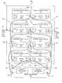
- FIG. 2shows a rear view of an embodiment of a properly cabled storage system 200 constructed in accordance with the invention.
- the storage system 200includes a rack 202 of enclosures 204 , 204 ′, 204 ′′, and 204 ′′′ (generally, enclosure 204 ) and a host processor enclosure 206 .
- the enclosures 204 of the storage system 200need not physically be in the same rack 202 , but can be in separate racks.
- the host processor enclosure 206is shown to be external to the rack 202 , in some embodiments the rack 202 includes the host processor enclosure 206 .
- each enclosure 204is a storage device having a plurality of disk modules.
- storage devicesinclude disk-array enclosures (DAE) and disk-array processor enclosures (DPE).
- DAEdisk-array enclosures
- DPEdisk-array processor enclosures
- a typical DAEincludes a plurality of disk modules (e.g., fifteen), one or two link control cards (LCCs), and one or two power supplies.
- a typical DPEincludes a plurality of disk modules (e.g., fifteen), one or two storage processors, one or two LCCs, and one or two power supplies.
- Disk modulesinclude a carrier assembly that holds a disk drive and slides into the enclosure 204 .
- Applications for the disk modulesinclude, for example, JBOD (Just a Bunch Of Disks), RAID (Redundant Array of Independent Disks), and SAN (Storage Area Network).
- each enclosure 204implements redundancy with an “A” side and a “B” side.
- Each sidehas a link control card (LCC) 208 and a power supply 212 .
- Reference numerals for the B side componentsare the same as corresponding components on the A side with the addition of a prime (′) designation.
- Each LCC 208 , 208 ′includes an primary communications port 216 , 216 ′ (generally, primary port 216 ) and an expansion communications port 220 , 220 ′ (generally, expansion port 220 ).
- the LCCs 208 , 208 ′are in electrical communication with each other over a plurality of midplane connections 210 .
- the host processor enclosure 206includes an A-side storage processor 222 and a B-side storage processor 222 ′. Each storage processor 222 , 222 ′ runs an operating system and uses the storage system 200 for data storage and retrieval.
- the storage system 200communicates over a plurality of backend networks (also referred to as a backend).
- a backendis a communication network by which the enclosures 204 , 206 can exchange communications (e.g., commands, messages, data, etc.) with each other.
- Topologies for backend networksvary. In one embodiment, each backend has a loop topology.
- the present inventioncan extend to backends of different topologies (e.g. token rings, Ethernet).
- the storage system 200communicates over a plurality of redundant backends, and associates an identifier (or value), e.g., a loop ID, with each redundant backend.
- a backendis a single network that connects a set of enclosures, and that a redundant backend is a plurality of separate backend networks that connect the same set of enclosures.
- Other embodiments of the storage system 200are connected to as many as eight backends.
- An embodiment of a storage system 200 implementing eight backends(identified by numbers 0 - 7 ), for example, includes at least eight enclosures, each enclosure being connected to one of the eight backends.
- each storage processor 222is in communication with each of the enclosures 204 by the redundant backends. Communication over backend 0 is through communications ports 228 , 228 ′ and over backend 1 is through communications ports 232 and 232 ′. The labels 0 and 1 adjacent to the communications ports identify the backend with which that communications port is associated. The communications ports 228 , 232 provide hardware pathways by which communication signals pass into and out of the host processor enclosure 206 .
- cables 236 , 236 ′connect communications ports 228 , 228 ′ to the respective primary port 216 , 216 ′ of the LCCs 208 , 208 ′. of the enclosure 204 , cables 240 , 240 ′ connect the respective expansion port 220 , 220 ′ of the LCCs 208 , 208 ′ of the enclosure 204 to the respective primary port 216 , 216 ′ of the LCCs 208 , 208 ′ of the enclosure 204 ′′, and cables 244 , 244 ′ connect the respective expansion port 220 , 220 ′ of the LCCs 208 , 208 ′ of the enclosure 204 ′′ to the primary port of an external enclosure (not shown).
- the cables 248 , 248 ′connect the communications ports 232 , 232 ′ to the respective primary port 216 , 216 of the LCCs 208 , 208 ′ of the enclosure 204 ′ and cables 252 , 252 ′ connect the respective expansion port 220 , 220 ′ of the LCCs 208 , 208 ′ of the enclosure 204 ′ to the respective primary port 216 , 216 ′ of the LCCs 208 , 208 ′ of the enclosure 204 ′′′.
- These backendsare illustrative only. The principles of the invention apply to backends that include more or fewer enclosures.
- each redundant backendincludes redundant loops that include the host processor 206 and enclosures 204 .
- each of the above-described cablesincludes two unidirectional paths in opposite directions. More specifically, the redundant loops associated with redundant backend 0 include the host processor enclosure 206 , the enclosures 204 and 204 ′′, and one or more other enclosures located in a different rack.
- the redundant loops associated with backend 1include the host processor enclosure 206 and the enclosures 204 ′ and 204 ′′′.
- the loopsare Fibre Channel arbitrated loops. Fibre Channel is a computer communications protocol for communicating data signals at a data rate of up to 2 Gbps.
- Fibre Channel protocolprovides an interface by which host processors (and servers) communicate with enclosures and with the disk modules installed within the enclosures.
- the Fibre Channel arbitrated loopcan support up to 126 nodes on the loop. In this embodiment, up to 120 disk modules and one storage processor are on the loop.
- the LCCs 208 , 208 ′ of an enclosure 204need to be connected to the same redundant backend.
- the primary port 216 of LCC 208 of the enclosure 204 ′is connected to the backend 0
- the primary port 216 ′ of the LCC 208 ′ of the enclosure 204 ′also needs to be connected to the backend 0 . If the LCCs 208 , 208 ′ are connected to different backend loop numbers, this mismatch is indicative of a system with an improperly connected cable.
- the storage processors 222 , 222 ′execute software that confirms whether the LCCs of an enclosure are connected to the same backend loop numbers, as described in more detail below. Also, the LCCs 208 of an enclosure 204 can each detect an improper cable connection and trigger an alarm to alert a user of the problem.
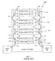
- FIG. 3shows an embodiment of an enclosure 204 having a comparator 300 that is used to determine whether the LCCs 208 , 208 ′ (FIG. 2) of the enclosure 204 are properly connected to the same backend loop number.
- the enclosure 204is representative of each of the enclosures 204 of FIG. 2 .
- the comparator 300includes a first circuit 304 , a second circuit 304 ′ and a midplane 308 .
- the LCC 208includes the first circuit 304 and the LCC 208 ′ includes the second circuit 304 ′.
- the midplane 308includes the midplane connections 210 (FIG. 2 ), which electrically connect the first circuit 304 to the second circuit 304 ′.
- the midplane 308is a functional equivalent of a backplane. Certain boards or cards (e.g., disk modules) plug into the midplane 308 from the front of the enclosure and other boards or cards, such as the LCCs 208 , plug into the midplane 308 from the rear of the enclosure.
- Each circuit 304 , 304 ′includes a buffer 312 , 312 ′, a write register 316 , 316 ′, a write identification (ID) bit register 320 , 320 ′, a read register 324 , 324 ′, read ID bit register 328 , 328 ′, output buffers 332 , 332 ′ and input buffers 336 , 336 ′, respectively.
- Electrical connections 340each connect one of the output buffers 332 to a different one of the input buffers 336 .
- the number of electrical connections 340depends upon the number of bits used to represent the range of possible backend identifiers. For example, in the embodiment shown, three of the electrical connections 340 are used to represent up to eight different backends.
- a fourth electrical connection 340is used for a single bit which indicates if the loop ID has been written to the LCC.
- Each of the electrical connections 340 of the first circuit 304is electrically connected by one of the midplane connections 210 of the midplane 308 to a corresponding one of the electrical connections 340 ′ of the second circuit 304 ′.
- each midplane connection 210produces a low output signal (i.e., “0” bit value) if either of the electrical connections 340 , 340 ′ has a “0” bit value.
- Each buffer 312is in electrical communication (directly or indirectly) with a respective one of the storage processors 222 , 222 ′ (FIG. 2) over a cable 344 , 344 ′.
- the cable 344can be any one of the cables 240 , 244 , 248 , or 252 shown in FIG. 2 (similarly, for cable 344 ′).
- the storage processor 222sends a broadcast message with a backend identifier of 0 over the communications port 228 (labeled 0 ) and message with a backend identifier of I over the communications port 232 (labeled 1 ).
- the storage processor 222 ′sends broadcast messages over communications ports 228 ′, 232 ′ containing backend identifiers 0 and 1 , respectively. Any enclosure receiving one or both of the broadcast messages from one or both of the storage processors 222 , 222 ′ processes each received message as described below.
- the LCC 208 of enclosure 204 ′receives a message with a loop ID of 0 and the LCC 208 ′ of enclosure 204 ′ receive another message with a loop ID of 1 .
- the backend identifiersare referred to as loop IDs.
- the mismatch of loop IDsindicates that there is an improper cable connection in the storage system 200 (not shown in FIG. 2 ).
- Each buffer 312 , 312 ′receives and stores the loop ID that it receives from the storage processor 222 , 222 ′, respectively, over the respective cable 344 , 344 ′.
- buffer 312receives the loop ID of 0
- buffer 312 ′receives the loop ID of 1
- each loop IDis represented by three-bit binary value, a “000b” for a loop ID of 0 and “001b” for the loop ID of 1 .
- Each buffer 312 , 312 ′forwards its received loop ID to the respective write register 316 , 316 ′, and the write registers 316 , 316 ′ place the stored three-bit binary value representing the loop ID onto the respective electrical connections 340 , 340 ′.
- One bitpasses on each electrical connection.
- the output buffers 332 , 332 ′electrically isolate the bit values on the electrical connections 340 , 340 ′, respectively, from the bit values stored in the write register 316 , 316 ′.
- the midplane connections 210may change the bit values on the electrical connections 340 , 340 ′ based on the loop IDs received by each of the circuits 304 , 304 ′. If the first circuit 304 received the same loop ID as the second circuit 304 ′, then the bit values on the electrical connection 340 , 340 ′ are the same, and consequently the midplane connections 210 do not cause a change in the bit values. This outcome is indicative, although not conclusive, of the cables being correctly connected in the storage system.
- the midplane connections 210“combine” the different loop ID bit values to produce a new bit value or values.
- the new bit values togetherare referred to as a composite loop ID (referred to generally as a composite identifier).
- the bit values for one loop IDare “000b” and for the other loop ID are “001b.” Because each midplane connection 210 produces a 0 bit-value if any one of the combined bit values is 0, the resulting bit values are “000” for a composite loop ID of 0 . Accordingly, the composite loop ID is the same as the loop ID received by the first circuit 304 , but different from the loop ID received by the second circuit 304 ′.
- this mismatchindicates that there is a improper cable connection in the storage system 200 which may be involve a cable that is connected to the present enclosure 204 or that is connected to an intervening enclosure (that is, in the loop between the present enclosure and the host processor enclosure 206 ).
- An alarm mechanism, described below in connection with FIG. 4, employed by each enclosure 204aids in pinpointing which enclosure has the improper cable connection.
- the resulting bit values representing the composite loop IDpass into each of the read registers 324 , 324 ′.
- the input buffers 336 , 336 ′electrically isolate the bit values stored in the read registers 324 , 324 ′ from the bit values on the electrical connections 340 , 340 ′.
- each storage processor 222 , 222 ′sends a message to each LCC 208 of enclosure 204 identifying the loop to which that enclosure 204 is connected.
- Each LCC 208 of each enclosure 204stores this loop ID for subsequent use (described below).
- a bit value(e.g., 1) is written to the appropriate read bit register 320 or 320 ′.
- the midplane connection 210combines the bit values stored in the read bit registers 320 , 320 ′ and the composite bit value passes to the write bit registers 328 , 328 ′.
- the write bit registers 328 , 328 ′each store a 0 bit value. From this bit value, the storage processors 222 , 222 ′ can determine whether a loop ID has been written to both LCCs (e.g., a 0 bit value indicating that the loop ID has not been written to one or both LCCs).
- FIG. 4shows an embodiment of a detector 400 used by the LCCs 208 of FIG. 2 to signal detection of an improper cable connection.
- Implementations of the detector 400can be in hardware, software, or a combination of both hardware and software (i.e., firmware).
- the detector 400includes a comparator 404 , the buffer 312 , read and write registers 324 , 316 and output and input buffers 332 , 336 of FIG. 3, a decoder 408 , and a plurality of light-emitting diodes (LEDs) 412 .
- LEDslight-emitting diodes
- the comparator 404includes a first input terminal for receiving a loop ID from the storage processor 222 (FIG. 2) over cable 344 and a second input terminal for receiving the bit values stored in the read register 324 through the buffer 312 .
- the bit values stored in the read register 324is the composite loop ID, which may or may not be different from the loop ID received from the storage processor 222 .
- An output terminal of the comparator 404is in electrical communication with the plurality of LEDs 412 .
- Each LED 412is associated with a particular backend.
- An alternative embodimentuses a numeric, (i.e., liquid crystal or LED based) display, instead of the LEDs 412 , to display a numeral that identifies a particular backend.
- the buffer 312 , read registers 324 , 328 , and write registers 316 , 320are in communication with each other and the midplane 308 as described above in FIG. 3 .
- the write register 316is in electrical communication with the decoder 408 .
- the decoder 408includes three input terminals and eight output terminals. Each of the three input terminals is in electrical communication with the write register 316 to receive a bit value. The bit values are obtained from the input side of the write output buffers 332 , which electrically isolates the bit values from the midplane 308 . Accordingly, the bit values that pass to the decoder 408 represent the loop ID that is received from the storage processor 222 .
- Each of the eight output terminalsis connected to one of the LEDs in the plurality of LEDs 412 .
- the comparator 404receives a loop ID over cable 344 that originates from the storage processor 222 .
- the loop IDalso passes through the buffer 312 and is stored in the write register 316 .
- the bit values representing the loop IDalso pass to the input terminals of the decoder 408 , which, based on the inputted bit values, asserts a signal on one of the output terminals that turns on the LED connected to that output terminal.
- the comparator 404reads the bit values stored in the read register 324 and compares those bit values with the bit values of the loop ID received over the cable 344 . If the bits values do not match, in one embodiment the comparator 404 sends a signal over the electrical connection 416 to the decoder 408 that causes the activated LED to flash. Note, if both LCCs 208 , 208 ′ of an enclosure 204 detect a mismatch, the enclosure has two flashing LEDs, one on each side (“A” and “B”) of the enclosure 204 .
- Users who are troubleshooting a storage system with an improperly connected cablecan locate the offending cable by looking specifically at the enclosure with one or more flashing LEDs. If more than one enclosure has a flashing LED, then the user can examine the enclosure that is closer in the loop to the host processor enclosure 206 . In a loop topology, a cable improperly connected to an enclosure nearer to the host processor enclosure 206 than other enclosure(s) can cause those other enclosure(s) to also have a flashing LED. Correcting the cabling for the nearer enclosure, therefore, can remedy the mismatches detected by the other enclosure(s).
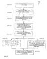
- FIG. 5shows an embodiment of a process 450 by which the storage system 200 of FIG. 2 determines whether there is an improper cable connection between enclosures.
- each storage processor 222 , 222 ′sends (step 454 ) a message to each LCC 208 of each enclosure 204 that stores the loop ID.
- the storage processors 222 , 222 ′each execute software that sends (step 458 ) out a broadcast message over each redundant backend.
- the broadcast messagesinclude an identifier that identifies the backend (or the loop) over which that message is traveling. Loop ID 0 passes over cables 228 , 228 ′, loop ID 1 passes over cables 232 , 232 ′.
- Each enclosure 204receives two loop ID signals, one on the A side and one on the B side.
- the loop ID circuits 304 , 304 ′ of each enclosure 204store (step 462 ) each received loop ID in the respective write register 316 , 316 ′.
- the midplane 308then combines (step 466 ) the bit values in these write registers 316 , 316 ′ to produce a composite loop ID.
- the composite loop IDis stored (step 470 ) in the respective read registers 324 , 324 ′.
- the LCCs 208 , 208 ′each compare (step 474 ) the composite loop ID with the loop ID that was originally received from the storage processor 222 , 222 ′, respectively. If the composite loop ID and the original loop ID do not match, then the LCC 208 , 208 signals (step 478 ) an alarm (e.g., audible and/or visible). In one embodiment, the LCC causes an LED to flash. The alarm indicates that different backends are connected to the enclosure.
- each storage processor 222 , 222 ′reads (step 482 ) the respective read register 324 , 324 ′ and compares the retrieved bit values with the loop ID that that storage processors 222 , 222 ′ sent over a cable. If the retrieved value does not match the sent value, then this is indicative of a cabling problem with the storage system 200 . An alert can then issue from the storage processor that detects the mismatch. For example, the storage processor 200 can record the detected mismatch in an error log that can be read later by a system user.
Landscapes
- Engineering & Computer Science (AREA)
- Theoretical Computer Science (AREA)
- General Engineering & Computer Science (AREA)
- Physics & Mathematics (AREA)
- General Physics & Mathematics (AREA)
- Quality & Reliability (AREA)
- Computer Hardware Design (AREA)
- Debugging And Monitoring (AREA)
Abstract
Description
Claims (20)
Priority Applications (1)
| Application Number | Priority Date | Filing Date | Title |
|---|---|---|---|
| US10/255,223US6809505B2 (en) | 2002-09-26 | 2002-09-26 | Storage system and method of detecting an improper cable connection in the storage system |
Applications Claiming Priority (1)
| Application Number | Priority Date | Filing Date | Title |
|---|---|---|---|
| US10/255,223US6809505B2 (en) | 2002-09-26 | 2002-09-26 | Storage system and method of detecting an improper cable connection in the storage system |
Publications (2)
| Publication Number | Publication Date |
|---|---|
| US20040061486A1 US20040061486A1 (en) | 2004-04-01 |
| US6809505B2true US6809505B2 (en) | 2004-10-26 |
Family
ID=32029079
Family Applications (1)
| Application Number | Title | Priority Date | Filing Date |
|---|---|---|---|
| US10/255,223Expired - LifetimeUS6809505B2 (en) | 2002-09-26 | 2002-09-26 | Storage system and method of detecting an improper cable connection in the storage system |
Country Status (1)
| Country | Link |
|---|---|
| US (1) | US6809505B2 (en) |
Cited By (16)
| Publication number | Priority date | Publication date | Assignee | Title |
|---|---|---|---|---|
| US20040117545A1 (en)* | 2002-12-16 | 2004-06-17 | Matthew Borsini | Using request and grant signals to read revision information from an adapter board that interfaces a disk drive |
| US20050135056A1 (en)* | 2003-12-17 | 2005-06-23 | Katsuyoshi Suzuki | Connection support method for disk array device |
| US20050210207A1 (en)* | 2004-03-11 | 2005-09-22 | Kenji Sekine | Maintenance terminal of disk array device |
| US20050246479A1 (en)* | 2004-04-30 | 2005-11-03 | Boulay Paul R | Guided configuration of data storage systems |
| US20060039289A1 (en)* | 2003-08-30 | 2006-02-23 | Reginald Beer | Method and apparatus for improved error avoidance in a redundant data path system |
| US20060056101A1 (en)* | 2004-09-02 | 2006-03-16 | Nec Corporation | Controller for a disk, disk enclosure device, disk array apparatus, method for detecting a fault of disk enclosure device, and signal-bearing medium |
| US20070018668A1 (en)* | 2005-07-22 | 2007-01-25 | Hon Hai Precision Industry Co., Ltd. | Testing system and testing method for a link control card |
| US20070109002A1 (en)* | 2005-11-17 | 2007-05-17 | Hon Hai Precision Industry Co., Ltd. | System and method for testing a link control card |
| US20080034122A1 (en)* | 2006-08-02 | 2008-02-07 | Robert Akira Kubo | Apparatus and Method to Detect Miscabling in a Storage Area Network |
| US20080224686A1 (en)* | 2007-03-13 | 2008-09-18 | Christian Boucher | System and method for remotely identifying a connected RF cable |
| US7502669B1 (en)* | 2006-06-26 | 2009-03-10 | Emc Corporation | Apparatus and method for graphically displaying disk drive enclosures and cabling in a data storage system |
| US20090126918A1 (en)* | 2005-12-27 | 2009-05-21 | Caterpillar Inc. | Heat exchanger using graphite foam |
| US7594134B1 (en)* | 2006-08-14 | 2009-09-22 | Network Appliance, Inc. | Dual access pathways to serially-connected mass data storage units |
| US20110246638A1 (en)* | 2010-03-31 | 2011-10-06 | Verizon Patent And Licensing Inc. | Method and system for providing monitoring of network environment changes |
| US8504857B1 (en) | 2008-09-30 | 2013-08-06 | Emc Corporation | Programmable availability for a high availability system |
| US20170293545A1 (en)* | 2016-04-06 | 2017-10-12 | Oracle International Corporation | Redundant cable routing management in storage systems |
Families Citing this family (10)
| Publication number | Priority date | Publication date | Assignee | Title |
|---|---|---|---|---|
| US8130084B2 (en)* | 2007-04-30 | 2012-03-06 | International Business Machines Corporation | Fault tolerant closed system control using power line communication |
| EP2015501A1 (en)* | 2007-07-09 | 2009-01-14 | ABB Technology AG | Identifying improper cabling of devices |
| US8421614B2 (en)* | 2007-09-19 | 2013-04-16 | International Business Machines Corporation | Reliable redundant data communication through alternating current power distribution system |
| US7870374B2 (en)* | 2007-09-27 | 2011-01-11 | International Business Machines Corporation | Validating physical and logical system connectivity of components in a data processing system |
| JP4685118B2 (en)* | 2008-01-30 | 2011-05-18 | 富士通株式会社 | Storage system and cable misconnection determination method |
| US9646112B2 (en)* | 2009-12-31 | 2017-05-09 | Teradata Us, Inc. | System, method, and computer-readable medium for providing a dynamic view and testing tool of power cabling of a multi-chassis computer system |
| WO2013140512A1 (en)* | 2012-03-19 | 2013-09-26 | 富士通株式会社 | Information processing device, connection error detection method, and connection error detection program |
| CN106161384A (en)* | 2015-04-15 | 2016-11-23 | 伊姆西公司 | For providing the method and system of the secure access to data in a mobile device |
| US10832536B2 (en) | 2018-12-07 | 2020-11-10 | International Business Machines Corporation | Guided cable management |
| US12197997B2 (en)* | 2020-03-09 | 2025-01-14 | Panduit Corp. | Cable management system and method |
Citations (11)
| Publication number | Priority date | Publication date | Assignee | Title |
|---|---|---|---|---|
| US5107532A (en)* | 1989-09-22 | 1992-04-21 | Cable Management International, Inc. | Automated documentation system for a communications network |
| US5448675A (en)* | 1994-06-09 | 1995-09-05 | At&T Ipm Corp. | Telecommunications distribution frame with tracing |
| US5522046A (en)* | 1991-05-01 | 1996-05-28 | Ncr Corporation | Communication system uses diagnostic processors and master processor module to identify faults and generate mapping tables to reconfigure communication paths in a multistage interconnect network |
| US5679987A (en)* | 1992-05-13 | 1997-10-21 | Ogawa; Hideharu | Method and device for obtaining connectivity information of telecommunication facilities |
| US5841997A (en) | 1995-09-29 | 1998-11-24 | Emc Corporation | Apparatus for effecting port switching of fibre channel loops |
| US5890214A (en) | 1996-02-27 | 1999-03-30 | Data General Corporation | Dynamically upgradeable disk array chassis and method for dynamically upgrading a data storage system utilizing a selectively switchable shunt |
| US5901151A (en) | 1996-02-27 | 1999-05-04 | Data General Corporation | System for orthogonal signal multiplexing |
| US20020046276A1 (en) | 2000-07-06 | 2002-04-18 | Coffey Aedan Diarmuid Cailean | Fibre channel diagnostics in a storage enclosure |
| US20020044562A1 (en) | 2000-09-07 | 2002-04-18 | Killen Odie Banks | Fibre-channel arbitrated-loop split loop operation |
| US6421711B1 (en)* | 1998-06-29 | 2002-07-16 | Emc Corporation | Virtual ports for data transferring of a data storage system |
| US6425049B1 (en) | 1999-02-08 | 2002-07-23 | Hitachi, Ltd. | Disk array system and method of changing the configuration of the disk array system |
- 2002
- 2002-09-26USUS10/255,223patent/US6809505B2/ennot_activeExpired - Lifetime
Patent Citations (11)
| Publication number | Priority date | Publication date | Assignee | Title |
|---|---|---|---|---|
| US5107532A (en)* | 1989-09-22 | 1992-04-21 | Cable Management International, Inc. | Automated documentation system for a communications network |
| US5522046A (en)* | 1991-05-01 | 1996-05-28 | Ncr Corporation | Communication system uses diagnostic processors and master processor module to identify faults and generate mapping tables to reconfigure communication paths in a multistage interconnect network |
| US5679987A (en)* | 1992-05-13 | 1997-10-21 | Ogawa; Hideharu | Method and device for obtaining connectivity information of telecommunication facilities |
| US5448675A (en)* | 1994-06-09 | 1995-09-05 | At&T Ipm Corp. | Telecommunications distribution frame with tracing |
| US5841997A (en) | 1995-09-29 | 1998-11-24 | Emc Corporation | Apparatus for effecting port switching of fibre channel loops |
| US5890214A (en) | 1996-02-27 | 1999-03-30 | Data General Corporation | Dynamically upgradeable disk array chassis and method for dynamically upgrading a data storage system utilizing a selectively switchable shunt |
| US5901151A (en) | 1996-02-27 | 1999-05-04 | Data General Corporation | System for orthogonal signal multiplexing |
| US6421711B1 (en)* | 1998-06-29 | 2002-07-16 | Emc Corporation | Virtual ports for data transferring of a data storage system |
| US6425049B1 (en) | 1999-02-08 | 2002-07-23 | Hitachi, Ltd. | Disk array system and method of changing the configuration of the disk array system |
| US20020046276A1 (en) | 2000-07-06 | 2002-04-18 | Coffey Aedan Diarmuid Cailean | Fibre channel diagnostics in a storage enclosure |
| US20020044562A1 (en) | 2000-09-07 | 2002-04-18 | Killen Odie Banks | Fibre-channel arbitrated-loop split loop operation |
Cited By (30)
| Publication number | Priority date | Publication date | Assignee | Title |
|---|---|---|---|---|
| US20040117545A1 (en)* | 2002-12-16 | 2004-06-17 | Matthew Borsini | Using request and grant signals to read revision information from an adapter board that interfaces a disk drive |
| US7065661B2 (en)* | 2002-12-16 | 2006-06-20 | Emc Corporation | Using request and grant signals to read revision information from an adapter board that interfaces a disk drive |
| US20060039289A1 (en)* | 2003-08-30 | 2006-02-23 | Reginald Beer | Method and apparatus for improved error avoidance in a redundant data path system |
| US7681082B2 (en)* | 2003-08-30 | 2010-03-16 | International Business Machines Corporation | Method and apparatus for improved error avoidance in a redundant data path system |
| US7370149B2 (en)* | 2003-12-17 | 2008-05-06 | Hitachi, Ltd. | Connection support method for disk array device |
| US7039752B2 (en)* | 2003-12-17 | 2006-05-02 | Hitachi, Ltd. | Connection support method for disk array device |
| US20060095667A1 (en)* | 2003-12-17 | 2006-05-04 | Katsuyoshi Suzuki | Connection support method for disk array device |
| US20050135056A1 (en)* | 2003-12-17 | 2005-06-23 | Katsuyoshi Suzuki | Connection support method for disk array device |
| US7225328B2 (en)* | 2004-03-11 | 2007-05-29 | Hitachi, Ltd. | Maintenance terminal of disk array device |
| US20050210207A1 (en)* | 2004-03-11 | 2005-09-22 | Kenji Sekine | Maintenance terminal of disk array device |
| US20050246479A1 (en)* | 2004-04-30 | 2005-11-03 | Boulay Paul R | Guided configuration of data storage systems |
| US7216192B2 (en)* | 2004-04-30 | 2007-05-08 | Pillar Data Systems, Inc. | Guided configuration of data storage systems |
| US7783929B2 (en)* | 2004-09-02 | 2010-08-24 | Nec Corporation | Controller for a disk, disk enclosure device, disk array apparatus, method for detecting a fault of disk enclosure device, and signal-bearing medium |
| US20060056101A1 (en)* | 2004-09-02 | 2006-03-16 | Nec Corporation | Controller for a disk, disk enclosure device, disk array apparatus, method for detecting a fault of disk enclosure device, and signal-bearing medium |
| US7480835B2 (en)* | 2005-07-22 | 2009-01-20 | Hong Fu Jin Precision Industry (Shenzhen) Co., Ltd. | Testing system and testing method for a link control card |
| US20070018668A1 (en)* | 2005-07-22 | 2007-01-25 | Hon Hai Precision Industry Co., Ltd. | Testing system and testing method for a link control card |
| US7479781B2 (en)* | 2005-11-17 | 2009-01-20 | Hong Fu Jin Precision Industry (Shenzhen) Co., Ltd. | System and method for testing a link control card |
| US20070109002A1 (en)* | 2005-11-17 | 2007-05-17 | Hon Hai Precision Industry Co., Ltd. | System and method for testing a link control card |
| CN100462935C (en)* | 2005-11-17 | 2009-02-18 | 鸿富锦精密工业(深圳)有限公司 | Link control card testing system and method |
| US20090126918A1 (en)* | 2005-12-27 | 2009-05-21 | Caterpillar Inc. | Heat exchanger using graphite foam |
| US7502669B1 (en)* | 2006-06-26 | 2009-03-10 | Emc Corporation | Apparatus and method for graphically displaying disk drive enclosures and cabling in a data storage system |
| US7694029B2 (en)* | 2006-08-02 | 2010-04-06 | International Business Machines Corporation | Detecting miscabling in a storage area network |
| US20080034122A1 (en)* | 2006-08-02 | 2008-02-07 | Robert Akira Kubo | Apparatus and Method to Detect Miscabling in a Storage Area Network |
| US7594134B1 (en)* | 2006-08-14 | 2009-09-22 | Network Appliance, Inc. | Dual access pathways to serially-connected mass data storage units |
| US20080224686A1 (en)* | 2007-03-13 | 2008-09-18 | Christian Boucher | System and method for remotely identifying a connected RF cable |
| US8504857B1 (en) | 2008-09-30 | 2013-08-06 | Emc Corporation | Programmable availability for a high availability system |
| US20110246638A1 (en)* | 2010-03-31 | 2011-10-06 | Verizon Patent And Licensing Inc. | Method and system for providing monitoring of network environment changes |
| US8862722B2 (en)* | 2010-03-31 | 2014-10-14 | Verizon Patent And Licensing Inc. | Method and system for providing monitoring of network environment changes |
| US20170293545A1 (en)* | 2016-04-06 | 2017-10-12 | Oracle International Corporation | Redundant cable routing management in storage systems |
| US9983970B2 (en)* | 2016-04-06 | 2018-05-29 | Oracle International Corporation | Redundant cable routing management in storage systems |
Also Published As
| Publication number | Publication date |
|---|---|
| US20040061486A1 (en) | 2004-04-01 |
Similar Documents
| Publication | Publication Date | Title |
|---|---|---|
| US6809505B2 (en) | Storage system and method of detecting an improper cable connection in the storage system | |
| US7085958B2 (en) | System and method for isolating a faulty switch, storage device or SFP in a daisy-chained configuration | |
| US7356638B2 (en) | Using out-of-band signaling to provide communication between storage controllers in a computer storage system | |
| US6889345B2 (en) | System and method for locating a failed storage device in a data storage system | |
| US7788523B2 (en) | Method and apparatus for relating device name to physical location of device on a network | |
| US6854052B2 (en) | Method to validate system configuration | |
| US8089903B2 (en) | Method and apparatus for providing a logical separation of a customer device and a service device connected to a data storage system | |
| US7669045B2 (en) | System and method for aggregating shelf IDs in a fibre channel storage loop | |
| US7861123B1 (en) | Managing loop interface failure | |
| CN111176913A (en) | A circuit and method for detecting Cable Port in a server | |
| US20040162928A1 (en) | High speed multiple ported bus interface reset control system | |
| US7194673B2 (en) | Detecting intermittent losses of synchronization in a fibre channel loop | |
| US7274673B2 (en) | Method and apparatus for detection of port name in a loop network | |
| US20080168161A1 (en) | Systems and methods for managing faults within a high speed network employing wide ports | |
| US7228338B2 (en) | Multi-service platform module | |
| US6901202B2 (en) | Storage system with a diskless enclosure | |
| US7486083B2 (en) | Managing system stability | |
| US20040162927A1 (en) | High speed multiple port data bus interface architecture | |
| US7681082B2 (en) | Method and apparatus for improved error avoidance in a redundant data path system | |
| US7464257B2 (en) | Mis-configuration detection methods and devices for blade systems | |
| US7539891B2 (en) | Switched FC-AL fault tolerant topology | |
| US7441078B1 (en) | Managing disk drive status | |
| JPH04101372A (en) | Misconnection detecting circuit |
Legal Events
| Date | Code | Title | Description |
|---|---|---|---|
| AS | Assignment | Owner name:EMC CORPORATION, MASSACHUSETTS Free format text:ASSIGNMENT OF ASSIGNORS INTEREST;ASSIGNOR:BAILEY, BRIAN K.;REEL/FRAME:013595/0519 Effective date:20021108 Owner name:EMC CORPORATION, MASSACHUSETTS Free format text:ASSIGNMENT OF ASSIGNORS INTEREST;ASSIGNORS:PEEKE, DOUGLAS E.;REID, GEOFFREY;TUTTLE, JAMES;REEL/FRAME:013595/0504 Effective date:20020925 | |
| STCF | Information on status: patent grant | Free format text:PATENTED CASE | |
| CC | Certificate of correction | ||
| FPAY | Fee payment | Year of fee payment:4 | |
| REMI | Maintenance fee reminder mailed | ||
| FEPP | Fee payment procedure | Free format text:PAYOR NUMBER ASSIGNED (ORIGINAL EVENT CODE: ASPN); ENTITY STATUS OF PATENT OWNER: LARGE ENTITY | |
| FPAY | Fee payment | Year of fee payment:8 | |
| FPAY | Fee payment | Year of fee payment:12 | |
| AS | Assignment | Owner name:CREDIT SUISSE AG, CAYMAN ISLANDS BRANCH, AS COLLATERAL AGENT, NORTH CAROLINA Free format text:SECURITY AGREEMENT;ASSIGNORS:ASAP SOFTWARE EXPRESS, INC.;AVENTAIL LLC;CREDANT TECHNOLOGIES, INC.;AND OTHERS;REEL/FRAME:040134/0001 Effective date:20160907 Owner name:THE BANK OF NEW YORK MELLON TRUST COMPANY, N.A., AS NOTES COLLATERAL AGENT, TEXAS Free format text:SECURITY AGREEMENT;ASSIGNORS:ASAP SOFTWARE EXPRESS, INC.;AVENTAIL LLC;CREDANT TECHNOLOGIES, INC.;AND OTHERS;REEL/FRAME:040136/0001 Effective date:20160907 Owner name:CREDIT SUISSE AG, CAYMAN ISLANDS BRANCH, AS COLLAT Free format text:SECURITY AGREEMENT;ASSIGNORS:ASAP SOFTWARE EXPRESS, INC.;AVENTAIL LLC;CREDANT TECHNOLOGIES, INC.;AND OTHERS;REEL/FRAME:040134/0001 Effective date:20160907 Owner name:THE BANK OF NEW YORK MELLON TRUST COMPANY, N.A., A Free format text:SECURITY AGREEMENT;ASSIGNORS:ASAP SOFTWARE EXPRESS, INC.;AVENTAIL LLC;CREDANT TECHNOLOGIES, INC.;AND OTHERS;REEL/FRAME:040136/0001 Effective date:20160907 | |
| AS | Assignment | Owner name:EMC IP HOLDING COMPANY LLC, MASSACHUSETTS Free format text:ASSIGNMENT OF ASSIGNORS INTEREST;ASSIGNOR:EMC CORPORATION;REEL/FRAME:040203/0001 Effective date:20160906 | |
| AS | Assignment | Owner name:THE BANK OF NEW YORK MELLON TRUST COMPANY, N.A., T Free format text:SECURITY AGREEMENT;ASSIGNORS:CREDANT TECHNOLOGIES, INC.;DELL INTERNATIONAL L.L.C.;DELL MARKETING L.P.;AND OTHERS;REEL/FRAME:049452/0223 Effective date:20190320 Owner name:THE BANK OF NEW YORK MELLON TRUST COMPANY, N.A., TEXAS Free format text:SECURITY AGREEMENT;ASSIGNORS:CREDANT TECHNOLOGIES, INC.;DELL INTERNATIONAL L.L.C.;DELL MARKETING L.P.;AND OTHERS;REEL/FRAME:049452/0223 Effective date:20190320 | |
| AS | Assignment | Owner name:THE BANK OF NEW YORK MELLON TRUST COMPANY, N.A., TEXAS Free format text:SECURITY AGREEMENT;ASSIGNORS:CREDANT TECHNOLOGIES INC.;DELL INTERNATIONAL L.L.C.;DELL MARKETING L.P.;AND OTHERS;REEL/FRAME:053546/0001 Effective date:20200409 | |
| AS | Assignment | Owner name:WYSE TECHNOLOGY L.L.C., CALIFORNIA Free format text:RELEASE BY SECURED PARTY;ASSIGNOR:CREDIT SUISSE AG, CAYMAN ISLANDS BRANCH;REEL/FRAME:058216/0001 Effective date:20211101 Owner name:SCALEIO LLC, MASSACHUSETTS Free format text:RELEASE BY SECURED PARTY;ASSIGNOR:CREDIT SUISSE AG, CAYMAN ISLANDS BRANCH;REEL/FRAME:058216/0001 Effective date:20211101 Owner name:MOZY, INC., WASHINGTON Free format text:RELEASE BY SECURED PARTY;ASSIGNOR:CREDIT SUISSE AG, CAYMAN ISLANDS BRANCH;REEL/FRAME:058216/0001 Effective date:20211101 Owner name:MAGINATICS LLC, CALIFORNIA Free format text:RELEASE BY SECURED PARTY;ASSIGNOR:CREDIT SUISSE AG, CAYMAN ISLANDS BRANCH;REEL/FRAME:058216/0001 Effective date:20211101 Owner name:FORCE10 NETWORKS, INC., CALIFORNIA Free format text:RELEASE BY SECURED PARTY;ASSIGNOR:CREDIT SUISSE AG, CAYMAN ISLANDS BRANCH;REEL/FRAME:058216/0001 Effective date:20211101 Owner name:EMC IP HOLDING COMPANY LLC, TEXAS Free format text:RELEASE BY SECURED PARTY;ASSIGNOR:CREDIT SUISSE AG, CAYMAN ISLANDS BRANCH;REEL/FRAME:058216/0001 Effective date:20211101 Owner name:EMC CORPORATION, MASSACHUSETTS Free format text:RELEASE BY SECURED PARTY;ASSIGNOR:CREDIT SUISSE AG, CAYMAN ISLANDS BRANCH;REEL/FRAME:058216/0001 Effective date:20211101 Owner name:DELL SYSTEMS CORPORATION, TEXAS Free format text:RELEASE BY SECURED PARTY;ASSIGNOR:CREDIT SUISSE AG, CAYMAN ISLANDS BRANCH;REEL/FRAME:058216/0001 Effective date:20211101 Owner name:DELL SOFTWARE INC., CALIFORNIA Free format text:RELEASE BY SECURED PARTY;ASSIGNOR:CREDIT SUISSE AG, CAYMAN ISLANDS BRANCH;REEL/FRAME:058216/0001 Effective date:20211101 Owner name:DELL PRODUCTS L.P., TEXAS Free format text:RELEASE BY SECURED PARTY;ASSIGNOR:CREDIT SUISSE AG, CAYMAN ISLANDS BRANCH;REEL/FRAME:058216/0001 Effective date:20211101 Owner name:DELL MARKETING L.P., TEXAS Free format text:RELEASE BY SECURED PARTY;ASSIGNOR:CREDIT SUISSE AG, CAYMAN ISLANDS BRANCH;REEL/FRAME:058216/0001 Effective date:20211101 Owner name:DELL INTERNATIONAL, L.L.C., TEXAS Free format text:RELEASE BY SECURED PARTY;ASSIGNOR:CREDIT SUISSE AG, CAYMAN ISLANDS BRANCH;REEL/FRAME:058216/0001 Effective date:20211101 Owner name:DELL USA L.P., TEXAS Free format text:RELEASE BY SECURED PARTY;ASSIGNOR:CREDIT SUISSE AG, CAYMAN ISLANDS BRANCH;REEL/FRAME:058216/0001 Effective date:20211101 Owner name:CREDANT TECHNOLOGIES, INC., TEXAS Free format text:RELEASE BY SECURED PARTY;ASSIGNOR:CREDIT SUISSE AG, CAYMAN ISLANDS BRANCH;REEL/FRAME:058216/0001 Effective date:20211101 Owner name:AVENTAIL LLC, CALIFORNIA Free format text:RELEASE BY SECURED PARTY;ASSIGNOR:CREDIT SUISSE AG, CAYMAN ISLANDS BRANCH;REEL/FRAME:058216/0001 Effective date:20211101 Owner name:ASAP SOFTWARE EXPRESS, INC., ILLINOIS Free format text:RELEASE BY SECURED PARTY;ASSIGNOR:CREDIT SUISSE AG, CAYMAN ISLANDS BRANCH;REEL/FRAME:058216/0001 Effective date:20211101 | |
| AS | Assignment | Owner name:SCALEIO LLC, MASSACHUSETTS Free format text:RELEASE OF SECURITY INTEREST IN PATENTS PREVIOUSLY RECORDED AT REEL/FRAME (040136/0001);ASSIGNOR:THE BANK OF NEW YORK MELLON TRUST COMPANY, N.A., AS NOTES COLLATERAL AGENT;REEL/FRAME:061324/0001 Effective date:20220329 Owner name:EMC IP HOLDING COMPANY LLC (ON BEHALF OF ITSELF AND AS SUCCESSOR-IN-INTEREST TO MOZY, INC.), TEXAS Free format text:RELEASE OF SECURITY INTEREST IN PATENTS PREVIOUSLY RECORDED AT REEL/FRAME (040136/0001);ASSIGNOR:THE BANK OF NEW YORK MELLON TRUST COMPANY, N.A., AS NOTES COLLATERAL AGENT;REEL/FRAME:061324/0001 Effective date:20220329 Owner name:EMC CORPORATION (ON BEHALF OF ITSELF AND AS SUCCESSOR-IN-INTEREST TO MAGINATICS LLC), MASSACHUSETTS Free format text:RELEASE OF SECURITY INTEREST IN PATENTS PREVIOUSLY RECORDED AT REEL/FRAME (040136/0001);ASSIGNOR:THE BANK OF NEW YORK MELLON TRUST COMPANY, N.A., AS NOTES COLLATERAL AGENT;REEL/FRAME:061324/0001 Effective date:20220329 Owner name:DELL MARKETING CORPORATION (SUCCESSOR-IN-INTEREST TO FORCE10 NETWORKS, INC. AND WYSE TECHNOLOGY L.L.C.), TEXAS Free format text:RELEASE OF SECURITY INTEREST IN PATENTS PREVIOUSLY RECORDED AT REEL/FRAME (040136/0001);ASSIGNOR:THE BANK OF NEW YORK MELLON TRUST COMPANY, N.A., AS NOTES COLLATERAL AGENT;REEL/FRAME:061324/0001 Effective date:20220329 Owner name:DELL PRODUCTS L.P., TEXAS Free format text:RELEASE OF SECURITY INTEREST IN PATENTS PREVIOUSLY RECORDED AT REEL/FRAME (040136/0001);ASSIGNOR:THE BANK OF NEW YORK MELLON TRUST COMPANY, N.A., AS NOTES COLLATERAL AGENT;REEL/FRAME:061324/0001 Effective date:20220329 Owner name:DELL INTERNATIONAL L.L.C., TEXAS Free format text:RELEASE OF SECURITY INTEREST IN PATENTS PREVIOUSLY RECORDED AT REEL/FRAME (040136/0001);ASSIGNOR:THE BANK OF NEW YORK MELLON TRUST COMPANY, N.A., AS NOTES COLLATERAL AGENT;REEL/FRAME:061324/0001 Effective date:20220329 Owner name:DELL USA L.P., TEXAS Free format text:RELEASE OF SECURITY INTEREST IN PATENTS PREVIOUSLY RECORDED AT REEL/FRAME (040136/0001);ASSIGNOR:THE BANK OF NEW YORK MELLON TRUST COMPANY, N.A., AS NOTES COLLATERAL AGENT;REEL/FRAME:061324/0001 Effective date:20220329 Owner name:DELL MARKETING L.P. (ON BEHALF OF ITSELF AND AS SUCCESSOR-IN-INTEREST TO CREDANT TECHNOLOGIES, INC.), TEXAS Free format text:RELEASE OF SECURITY INTEREST IN PATENTS PREVIOUSLY RECORDED AT REEL/FRAME (040136/0001);ASSIGNOR:THE BANK OF NEW YORK MELLON TRUST COMPANY, N.A., AS NOTES COLLATERAL AGENT;REEL/FRAME:061324/0001 Effective date:20220329 Owner name:DELL MARKETING CORPORATION (SUCCESSOR-IN-INTEREST TO ASAP SOFTWARE EXPRESS, INC.), TEXAS Free format text:RELEASE OF SECURITY INTEREST IN PATENTS PREVIOUSLY RECORDED AT REEL/FRAME (040136/0001);ASSIGNOR:THE BANK OF NEW YORK MELLON TRUST COMPANY, N.A., AS NOTES COLLATERAL AGENT;REEL/FRAME:061324/0001 Effective date:20220329 | |
| AS | Assignment | Owner name:SCALEIO LLC, MASSACHUSETTS Free format text:RELEASE OF SECURITY INTEREST IN PATENTS PREVIOUSLY RECORDED AT REEL/FRAME (045455/0001);ASSIGNOR:THE BANK OF NEW YORK MELLON TRUST COMPANY, N.A., AS NOTES COLLATERAL AGENT;REEL/FRAME:061753/0001 Effective date:20220329 Owner name:EMC IP HOLDING COMPANY LLC (ON BEHALF OF ITSELF AND AS SUCCESSOR-IN-INTEREST TO MOZY, INC.), TEXAS Free format text:RELEASE OF SECURITY INTEREST IN PATENTS PREVIOUSLY RECORDED AT REEL/FRAME (045455/0001);ASSIGNOR:THE BANK OF NEW YORK MELLON TRUST COMPANY, N.A., AS NOTES COLLATERAL AGENT;REEL/FRAME:061753/0001 Effective date:20220329 Owner name:EMC CORPORATION (ON BEHALF OF ITSELF AND AS SUCCESSOR-IN-INTEREST TO MAGINATICS LLC), MASSACHUSETTS Free format text:RELEASE OF SECURITY INTEREST IN PATENTS PREVIOUSLY RECORDED AT REEL/FRAME (045455/0001);ASSIGNOR:THE BANK OF NEW YORK MELLON TRUST COMPANY, N.A., AS NOTES COLLATERAL AGENT;REEL/FRAME:061753/0001 Effective date:20220329 Owner name:DELL MARKETING CORPORATION (SUCCESSOR-IN-INTEREST TO FORCE10 NETWORKS, INC. AND WYSE TECHNOLOGY L.L.C.), TEXAS Free format text:RELEASE OF SECURITY INTEREST IN PATENTS PREVIOUSLY RECORDED AT REEL/FRAME (045455/0001);ASSIGNOR:THE BANK OF NEW YORK MELLON TRUST COMPANY, N.A., AS NOTES COLLATERAL AGENT;REEL/FRAME:061753/0001 Effective date:20220329 Owner name:DELL PRODUCTS L.P., TEXAS Free format text:RELEASE OF SECURITY INTEREST IN PATENTS PREVIOUSLY RECORDED AT REEL/FRAME (045455/0001);ASSIGNOR:THE BANK OF NEW YORK MELLON TRUST COMPANY, N.A., AS NOTES COLLATERAL AGENT;REEL/FRAME:061753/0001 Effective date:20220329 Owner name:DELL INTERNATIONAL L.L.C., TEXAS Free format text:RELEASE OF SECURITY INTEREST IN PATENTS PREVIOUSLY RECORDED AT REEL/FRAME (045455/0001);ASSIGNOR:THE BANK OF NEW YORK MELLON TRUST COMPANY, N.A., AS NOTES COLLATERAL AGENT;REEL/FRAME:061753/0001 Effective date:20220329 Owner name:DELL USA L.P., TEXAS Free format text:RELEASE OF SECURITY INTEREST IN PATENTS PREVIOUSLY RECORDED AT REEL/FRAME (045455/0001);ASSIGNOR:THE BANK OF NEW YORK MELLON TRUST COMPANY, N.A., AS NOTES COLLATERAL AGENT;REEL/FRAME:061753/0001 Effective date:20220329 Owner name:DELL MARKETING L.P. (ON BEHALF OF ITSELF AND AS SUCCESSOR-IN-INTEREST TO CREDANT TECHNOLOGIES, INC.), TEXAS Free format text:RELEASE OF SECURITY INTEREST IN PATENTS PREVIOUSLY RECORDED AT REEL/FRAME (045455/0001);ASSIGNOR:THE BANK OF NEW YORK MELLON TRUST COMPANY, N.A., AS NOTES COLLATERAL AGENT;REEL/FRAME:061753/0001 Effective date:20220329 Owner name:DELL MARKETING CORPORATION (SUCCESSOR-IN-INTEREST TO ASAP SOFTWARE EXPRESS, INC.), TEXAS Free format text:RELEASE OF SECURITY INTEREST IN PATENTS PREVIOUSLY RECORDED AT REEL/FRAME (045455/0001);ASSIGNOR:THE BANK OF NEW YORK MELLON TRUST COMPANY, N.A., AS NOTES COLLATERAL AGENT;REEL/FRAME:061753/0001 Effective date:20220329 | |
| AS | Assignment | Owner name:DELL MARKETING L.P. (ON BEHALF OF ITSELF AND AS SUCCESSOR-IN-INTEREST TO CREDANT TECHNOLOGIES, INC.), TEXAS Free format text:RELEASE OF SECURITY INTEREST IN PATENTS PREVIOUSLY RECORDED AT REEL/FRAME (053546/0001);ASSIGNOR:THE BANK OF NEW YORK MELLON TRUST COMPANY, N.A., AS NOTES COLLATERAL AGENT;REEL/FRAME:071642/0001 Effective date:20220329 Owner name:DELL INTERNATIONAL L.L.C., TEXAS Free format text:RELEASE OF SECURITY INTEREST IN PATENTS PREVIOUSLY RECORDED AT REEL/FRAME (053546/0001);ASSIGNOR:THE BANK OF NEW YORK MELLON TRUST COMPANY, N.A., AS NOTES COLLATERAL AGENT;REEL/FRAME:071642/0001 Effective date:20220329 Owner name:DELL PRODUCTS L.P., TEXAS Free format text:RELEASE OF SECURITY INTEREST IN PATENTS PREVIOUSLY RECORDED AT REEL/FRAME (053546/0001);ASSIGNOR:THE BANK OF NEW YORK MELLON TRUST COMPANY, N.A., AS NOTES COLLATERAL AGENT;REEL/FRAME:071642/0001 Effective date:20220329 Owner name:DELL USA L.P., TEXAS Free format text:RELEASE OF SECURITY INTEREST IN PATENTS PREVIOUSLY RECORDED AT REEL/FRAME (053546/0001);ASSIGNOR:THE BANK OF NEW YORK MELLON TRUST COMPANY, N.A., AS NOTES COLLATERAL AGENT;REEL/FRAME:071642/0001 Effective date:20220329 Owner name:EMC CORPORATION, MASSACHUSETTS Free format text:RELEASE OF SECURITY INTEREST IN PATENTS PREVIOUSLY RECORDED AT REEL/FRAME (053546/0001);ASSIGNOR:THE BANK OF NEW YORK MELLON TRUST COMPANY, N.A., AS NOTES COLLATERAL AGENT;REEL/FRAME:071642/0001 Effective date:20220329 Owner name:DELL MARKETING CORPORATION (SUCCESSOR-IN-INTEREST TO FORCE10 NETWORKS, INC. AND WYSE TECHNOLOGY L.L.C.), TEXAS Free format text:RELEASE OF SECURITY INTEREST IN PATENTS PREVIOUSLY RECORDED AT REEL/FRAME (053546/0001);ASSIGNOR:THE BANK OF NEW YORK MELLON TRUST COMPANY, N.A., AS NOTES COLLATERAL AGENT;REEL/FRAME:071642/0001 Effective date:20220329 Owner name:EMC IP HOLDING COMPANY LLC, TEXAS Free format text:RELEASE OF SECURITY INTEREST IN PATENTS PREVIOUSLY RECORDED AT REEL/FRAME (053546/0001);ASSIGNOR:THE BANK OF NEW YORK MELLON TRUST COMPANY, N.A., AS NOTES COLLATERAL AGENT;REEL/FRAME:071642/0001 Effective date:20220329 |