US6808538B2 - Vertebral body spacer having variable wedged endplates - Google Patents
Vertebral body spacer having variable wedged endplatesDownload PDFInfo
- Publication number
- US6808538B2 US6808538B2US10/099,693US9969302AUS6808538B2US 6808538 B2US6808538 B2US 6808538B2US 9969302 AUS9969302 AUS 9969302AUS 6808538 B2US6808538 B2US 6808538B2
- Authority
- US
- United States
- Prior art keywords
- spacer
- endplate
- main body
- socket
- planes
- Prior art date
- Legal status (The legal status is an assumption and is not a legal conclusion. Google has not performed a legal analysis and makes no representation as to the accuracy of the status listed.)
- Expired - Lifetime, expires
Links
Images


Classifications
- A—HUMAN NECESSITIES
- A61—MEDICAL OR VETERINARY SCIENCE; HYGIENE
- A61F—FILTERS IMPLANTABLE INTO BLOOD VESSELS; PROSTHESES; DEVICES PROVIDING PATENCY TO, OR PREVENTING COLLAPSING OF, TUBULAR STRUCTURES OF THE BODY, e.g. STENTS; ORTHOPAEDIC, NURSING OR CONTRACEPTIVE DEVICES; FOMENTATION; TREATMENT OR PROTECTION OF EYES OR EARS; BANDAGES, DRESSINGS OR ABSORBENT PADS; FIRST-AID KITS
- A61F2/00—Filters implantable into blood vessels; Prostheses, i.e. artificial substitutes or replacements for parts of the body; Appliances for connecting them with the body; Devices providing patency to, or preventing collapsing of, tubular structures of the body, e.g. stents
- A61F2/02—Prostheses implantable into the body
- A61F2/30—Joints
- A61F2/44—Joints for the spine, e.g. vertebrae, spinal discs
- A61F2/4455—Joints for the spine, e.g. vertebrae, spinal discs for the fusion of spinal bodies, e.g. intervertebral fusion of adjacent spinal bodies, e.g. fusion cages
- A61F2/4465—Joints for the spine, e.g. vertebrae, spinal discs for the fusion of spinal bodies, e.g. intervertebral fusion of adjacent spinal bodies, e.g. fusion cages having a circular or kidney shaped cross-section substantially perpendicular to the axis of the spine
- A—HUMAN NECESSITIES
- A61—MEDICAL OR VETERINARY SCIENCE; HYGIENE
- A61F—FILTERS IMPLANTABLE INTO BLOOD VESSELS; PROSTHESES; DEVICES PROVIDING PATENCY TO, OR PREVENTING COLLAPSING OF, TUBULAR STRUCTURES OF THE BODY, e.g. STENTS; ORTHOPAEDIC, NURSING OR CONTRACEPTIVE DEVICES; FOMENTATION; TREATMENT OR PROTECTION OF EYES OR EARS; BANDAGES, DRESSINGS OR ABSORBENT PADS; FIRST-AID KITS
- A61F2/00—Filters implantable into blood vessels; Prostheses, i.e. artificial substitutes or replacements for parts of the body; Appliances for connecting them with the body; Devices providing patency to, or preventing collapsing of, tubular structures of the body, e.g. stents
- A61F2/02—Prostheses implantable into the body
- A61F2/28—Bones
- A61F2002/2835—Bone graft implants for filling a bony defect or an endoprosthesis cavity, e.g. by synthetic material or biological material
- A—HUMAN NECESSITIES
- A61—MEDICAL OR VETERINARY SCIENCE; HYGIENE
- A61F—FILTERS IMPLANTABLE INTO BLOOD VESSELS; PROSTHESES; DEVICES PROVIDING PATENCY TO, OR PREVENTING COLLAPSING OF, TUBULAR STRUCTURES OF THE BODY, e.g. STENTS; ORTHOPAEDIC, NURSING OR CONTRACEPTIVE DEVICES; FOMENTATION; TREATMENT OR PROTECTION OF EYES OR EARS; BANDAGES, DRESSINGS OR ABSORBENT PADS; FIRST-AID KITS
- A61F2/00—Filters implantable into blood vessels; Prostheses, i.e. artificial substitutes or replacements for parts of the body; Appliances for connecting them with the body; Devices providing patency to, or preventing collapsing of, tubular structures of the body, e.g. stents
- A61F2/02—Prostheses implantable into the body
- A61F2/30—Joints
- A61F2002/30001—Additional features of subject-matter classified in A61F2/28, A61F2/30 and subgroups thereof
- A61F2002/30108—Shapes
- A61F2002/30199—Three-dimensional shapes
- A61F2002/30224—Three-dimensional shapes cylindrical
- A61F2002/30228—Cylinders of elliptical or oval basis
- A—HUMAN NECESSITIES
- A61—MEDICAL OR VETERINARY SCIENCE; HYGIENE
- A61F—FILTERS IMPLANTABLE INTO BLOOD VESSELS; PROSTHESES; DEVICES PROVIDING PATENCY TO, OR PREVENTING COLLAPSING OF, TUBULAR STRUCTURES OF THE BODY, e.g. STENTS; ORTHOPAEDIC, NURSING OR CONTRACEPTIVE DEVICES; FOMENTATION; TREATMENT OR PROTECTION OF EYES OR EARS; BANDAGES, DRESSINGS OR ABSORBENT PADS; FIRST-AID KITS
- A61F2/00—Filters implantable into blood vessels; Prostheses, i.e. artificial substitutes or replacements for parts of the body; Appliances for connecting them with the body; Devices providing patency to, or preventing collapsing of, tubular structures of the body, e.g. stents
- A61F2/02—Prostheses implantable into the body
- A61F2/30—Joints
- A61F2002/30001—Additional features of subject-matter classified in A61F2/28, A61F2/30 and subgroups thereof
- A61F2002/30108—Shapes
- A61F2002/30199—Three-dimensional shapes
- A61F2002/30224—Three-dimensional shapes cylindrical
- A61F2002/30235—Three-dimensional shapes cylindrical tubular, e.g. sleeves
- A—HUMAN NECESSITIES
- A61—MEDICAL OR VETERINARY SCIENCE; HYGIENE
- A61F—FILTERS IMPLANTABLE INTO BLOOD VESSELS; PROSTHESES; DEVICES PROVIDING PATENCY TO, OR PREVENTING COLLAPSING OF, TUBULAR STRUCTURES OF THE BODY, e.g. STENTS; ORTHOPAEDIC, NURSING OR CONTRACEPTIVE DEVICES; FOMENTATION; TREATMENT OR PROTECTION OF EYES OR EARS; BANDAGES, DRESSINGS OR ABSORBENT PADS; FIRST-AID KITS
- A61F2/00—Filters implantable into blood vessels; Prostheses, i.e. artificial substitutes or replacements for parts of the body; Appliances for connecting them with the body; Devices providing patency to, or preventing collapsing of, tubular structures of the body, e.g. stents
- A61F2/02—Prostheses implantable into the body
- A61F2/30—Joints
- A61F2002/30001—Additional features of subject-matter classified in A61F2/28, A61F2/30 and subgroups thereof
- A61F2002/30316—The prosthesis having different structural features at different locations within the same prosthesis; Connections between prosthetic parts; Special structural features of bone or joint prostheses not otherwise provided for
- A61F2002/30329—Connections or couplings between prosthetic parts, e.g. between modular parts; Connecting elements
- A61F2002/30331—Connections or couplings between prosthetic parts, e.g. between modular parts; Connecting elements made by longitudinally pushing a protrusion into a complementarily-shaped recess, e.g. held by friction fit
- A61F2002/30378—Spherically-shaped protrusion and recess
- A—HUMAN NECESSITIES
- A61—MEDICAL OR VETERINARY SCIENCE; HYGIENE
- A61F—FILTERS IMPLANTABLE INTO BLOOD VESSELS; PROSTHESES; DEVICES PROVIDING PATENCY TO, OR PREVENTING COLLAPSING OF, TUBULAR STRUCTURES OF THE BODY, e.g. STENTS; ORTHOPAEDIC, NURSING OR CONTRACEPTIVE DEVICES; FOMENTATION; TREATMENT OR PROTECTION OF EYES OR EARS; BANDAGES, DRESSINGS OR ABSORBENT PADS; FIRST-AID KITS
- A61F2/00—Filters implantable into blood vessels; Prostheses, i.e. artificial substitutes or replacements for parts of the body; Appliances for connecting them with the body; Devices providing patency to, or preventing collapsing of, tubular structures of the body, e.g. stents
- A61F2/02—Prostheses implantable into the body
- A61F2/30—Joints
- A61F2002/30001—Additional features of subject-matter classified in A61F2/28, A61F2/30 and subgroups thereof
- A61F2002/30316—The prosthesis having different structural features at different locations within the same prosthesis; Connections between prosthetic parts; Special structural features of bone or joint prostheses not otherwise provided for
- A61F2002/30329—Connections or couplings between prosthetic parts, e.g. between modular parts; Connecting elements
- A61F2002/30476—Connections or couplings between prosthetic parts, e.g. between modular parts; Connecting elements locked by an additional locking mechanism
- A61F2002/305—Snap connection
- A—HUMAN NECESSITIES
- A61—MEDICAL OR VETERINARY SCIENCE; HYGIENE
- A61F—FILTERS IMPLANTABLE INTO BLOOD VESSELS; PROSTHESES; DEVICES PROVIDING PATENCY TO, OR PREVENTING COLLAPSING OF, TUBULAR STRUCTURES OF THE BODY, e.g. STENTS; ORTHOPAEDIC, NURSING OR CONTRACEPTIVE DEVICES; FOMENTATION; TREATMENT OR PROTECTION OF EYES OR EARS; BANDAGES, DRESSINGS OR ABSORBENT PADS; FIRST-AID KITS
- A61F2/00—Filters implantable into blood vessels; Prostheses, i.e. artificial substitutes or replacements for parts of the body; Appliances for connecting them with the body; Devices providing patency to, or preventing collapsing of, tubular structures of the body, e.g. stents
- A61F2/02—Prostheses implantable into the body
- A61F2/30—Joints
- A61F2002/30001—Additional features of subject-matter classified in A61F2/28, A61F2/30 and subgroups thereof
- A61F2002/30316—The prosthesis having different structural features at different locations within the same prosthesis; Connections between prosthetic parts; Special structural features of bone or joint prostheses not otherwise provided for
- A61F2002/30535—Special structural features of bone or joint prostheses not otherwise provided for
- A61F2002/30537—Special structural features of bone or joint prostheses not otherwise provided for adjustable
- A61F2002/30538—Special structural features of bone or joint prostheses not otherwise provided for adjustable for adjusting angular orientation
- A—HUMAN NECESSITIES
- A61—MEDICAL OR VETERINARY SCIENCE; HYGIENE
- A61F—FILTERS IMPLANTABLE INTO BLOOD VESSELS; PROSTHESES; DEVICES PROVIDING PATENCY TO, OR PREVENTING COLLAPSING OF, TUBULAR STRUCTURES OF THE BODY, e.g. STENTS; ORTHOPAEDIC, NURSING OR CONTRACEPTIVE DEVICES; FOMENTATION; TREATMENT OR PROTECTION OF EYES OR EARS; BANDAGES, DRESSINGS OR ABSORBENT PADS; FIRST-AID KITS
- A61F2/00—Filters implantable into blood vessels; Prostheses, i.e. artificial substitutes or replacements for parts of the body; Appliances for connecting them with the body; Devices providing patency to, or preventing collapsing of, tubular structures of the body, e.g. stents
- A61F2/02—Prostheses implantable into the body
- A61F2/30—Joints
- A61F2002/30001—Additional features of subject-matter classified in A61F2/28, A61F2/30 and subgroups thereof
- A61F2002/30316—The prosthesis having different structural features at different locations within the same prosthesis; Connections between prosthetic parts; Special structural features of bone or joint prostheses not otherwise provided for
- A61F2002/30535—Special structural features of bone or joint prostheses not otherwise provided for
- A61F2002/30574—Special structural features of bone or joint prostheses not otherwise provided for with an integral complete or partial collar or flange
- A—HUMAN NECESSITIES
- A61—MEDICAL OR VETERINARY SCIENCE; HYGIENE
- A61F—FILTERS IMPLANTABLE INTO BLOOD VESSELS; PROSTHESES; DEVICES PROVIDING PATENCY TO, OR PREVENTING COLLAPSING OF, TUBULAR STRUCTURES OF THE BODY, e.g. STENTS; ORTHOPAEDIC, NURSING OR CONTRACEPTIVE DEVICES; FOMENTATION; TREATMENT OR PROTECTION OF EYES OR EARS; BANDAGES, DRESSINGS OR ABSORBENT PADS; FIRST-AID KITS
- A61F2/00—Filters implantable into blood vessels; Prostheses, i.e. artificial substitutes or replacements for parts of the body; Appliances for connecting them with the body; Devices providing patency to, or preventing collapsing of, tubular structures of the body, e.g. stents
- A61F2/02—Prostheses implantable into the body
- A61F2/30—Joints
- A61F2002/30001—Additional features of subject-matter classified in A61F2/28, A61F2/30 and subgroups thereof
- A61F2002/30316—The prosthesis having different structural features at different locations within the same prosthesis; Connections between prosthetic parts; Special structural features of bone or joint prostheses not otherwise provided for
- A61F2002/30535—Special structural features of bone or joint prostheses not otherwise provided for
- A61F2002/30593—Special structural features of bone or joint prostheses not otherwise provided for hollow
- A—HUMAN NECESSITIES
- A61—MEDICAL OR VETERINARY SCIENCE; HYGIENE
- A61F—FILTERS IMPLANTABLE INTO BLOOD VESSELS; PROSTHESES; DEVICES PROVIDING PATENCY TO, OR PREVENTING COLLAPSING OF, TUBULAR STRUCTURES OF THE BODY, e.g. STENTS; ORTHOPAEDIC, NURSING OR CONTRACEPTIVE DEVICES; FOMENTATION; TREATMENT OR PROTECTION OF EYES OR EARS; BANDAGES, DRESSINGS OR ABSORBENT PADS; FIRST-AID KITS
- A61F2/00—Filters implantable into blood vessels; Prostheses, i.e. artificial substitutes or replacements for parts of the body; Appliances for connecting them with the body; Devices providing patency to, or preventing collapsing of, tubular structures of the body, e.g. stents
- A61F2/02—Prostheses implantable into the body
- A61F2/30—Joints
- A61F2002/30001—Additional features of subject-matter classified in A61F2/28, A61F2/30 and subgroups thereof
- A61F2002/30621—Features concerning the anatomical functioning or articulation of the prosthetic joint
- A61F2002/30649—Ball-and-socket joints
- A61F2002/30665—Dual arrangement of two adjacent ball-and-socket joints
- A—HUMAN NECESSITIES
- A61—MEDICAL OR VETERINARY SCIENCE; HYGIENE
- A61F—FILTERS IMPLANTABLE INTO BLOOD VESSELS; PROSTHESES; DEVICES PROVIDING PATENCY TO, OR PREVENTING COLLAPSING OF, TUBULAR STRUCTURES OF THE BODY, e.g. STENTS; ORTHOPAEDIC, NURSING OR CONTRACEPTIVE DEVICES; FOMENTATION; TREATMENT OR PROTECTION OF EYES OR EARS; BANDAGES, DRESSINGS OR ABSORBENT PADS; FIRST-AID KITS
- A61F2/00—Filters implantable into blood vessels; Prostheses, i.e. artificial substitutes or replacements for parts of the body; Appliances for connecting them with the body; Devices providing patency to, or preventing collapsing of, tubular structures of the body, e.g. stents
- A61F2/02—Prostheses implantable into the body
- A61F2/30—Joints
- A61F2/30767—Special external or bone-contacting surface, e.g. coating for improving bone ingrowth
- A61F2/30771—Special external or bone-contacting surface, e.g. coating for improving bone ingrowth applied in original prostheses, e.g. holes or grooves
- A61F2002/30772—Apertures or holes, e.g. of circular cross section
- A61F2002/30784—Plurality of holes
- A—HUMAN NECESSITIES
- A61—MEDICAL OR VETERINARY SCIENCE; HYGIENE
- A61F—FILTERS IMPLANTABLE INTO BLOOD VESSELS; PROSTHESES; DEVICES PROVIDING PATENCY TO, OR PREVENTING COLLAPSING OF, TUBULAR STRUCTURES OF THE BODY, e.g. STENTS; ORTHOPAEDIC, NURSING OR CONTRACEPTIVE DEVICES; FOMENTATION; TREATMENT OR PROTECTION OF EYES OR EARS; BANDAGES, DRESSINGS OR ABSORBENT PADS; FIRST-AID KITS
- A61F2/00—Filters implantable into blood vessels; Prostheses, i.e. artificial substitutes or replacements for parts of the body; Appliances for connecting them with the body; Devices providing patency to, or preventing collapsing of, tubular structures of the body, e.g. stents
- A61F2/02—Prostheses implantable into the body
- A61F2/30—Joints
- A61F2/30767—Special external or bone-contacting surface, e.g. coating for improving bone ingrowth
- A61F2/30771—Special external or bone-contacting surface, e.g. coating for improving bone ingrowth applied in original prostheses, e.g. holes or grooves
- A61F2002/30841—Sharp anchoring protrusions for impaction into the bone, e.g. sharp pins, spikes
- A—HUMAN NECESSITIES
- A61—MEDICAL OR VETERINARY SCIENCE; HYGIENE
- A61F—FILTERS IMPLANTABLE INTO BLOOD VESSELS; PROSTHESES; DEVICES PROVIDING PATENCY TO, OR PREVENTING COLLAPSING OF, TUBULAR STRUCTURES OF THE BODY, e.g. STENTS; ORTHOPAEDIC, NURSING OR CONTRACEPTIVE DEVICES; FOMENTATION; TREATMENT OR PROTECTION OF EYES OR EARS; BANDAGES, DRESSINGS OR ABSORBENT PADS; FIRST-AID KITS
- A61F2/00—Filters implantable into blood vessels; Prostheses, i.e. artificial substitutes or replacements for parts of the body; Appliances for connecting them with the body; Devices providing patency to, or preventing collapsing of, tubular structures of the body, e.g. stents
- A61F2/02—Prostheses implantable into the body
- A61F2/30—Joints
- A61F2/44—Joints for the spine, e.g. vertebrae, spinal discs
- A61F2/442—Intervertebral or spinal discs, e.g. resilient
- A61F2/4425—Intervertebral or spinal discs, e.g. resilient made of articulated components
- A61F2002/443—Intervertebral or spinal discs, e.g. resilient made of articulated components having two transversal endplates and at least one intermediate component
- A—HUMAN NECESSITIES
- A61—MEDICAL OR VETERINARY SCIENCE; HYGIENE
- A61F—FILTERS IMPLANTABLE INTO BLOOD VESSELS; PROSTHESES; DEVICES PROVIDING PATENCY TO, OR PREVENTING COLLAPSING OF, TUBULAR STRUCTURES OF THE BODY, e.g. STENTS; ORTHOPAEDIC, NURSING OR CONTRACEPTIVE DEVICES; FOMENTATION; TREATMENT OR PROTECTION OF EYES OR EARS; BANDAGES, DRESSINGS OR ABSORBENT PADS; FIRST-AID KITS
- A61F2220/00—Fixations or connections for prostheses classified in groups A61F2/00 - A61F2/26 or A61F2/82 or A61F9/00 or A61F11/00 or subgroups thereof
- A61F2220/0025—Connections or couplings between prosthetic parts, e.g. between modular parts; Connecting elements
- A61F2220/0033—Connections or couplings between prosthetic parts, e.g. between modular parts; Connecting elements made by longitudinally pushing a protrusion into a complementary-shaped recess, e.g. held by friction fit
- A—HUMAN NECESSITIES
- A61—MEDICAL OR VETERINARY SCIENCE; HYGIENE
- A61F—FILTERS IMPLANTABLE INTO BLOOD VESSELS; PROSTHESES; DEVICES PROVIDING PATENCY TO, OR PREVENTING COLLAPSING OF, TUBULAR STRUCTURES OF THE BODY, e.g. STENTS; ORTHOPAEDIC, NURSING OR CONTRACEPTIVE DEVICES; FOMENTATION; TREATMENT OR PROTECTION OF EYES OR EARS; BANDAGES, DRESSINGS OR ABSORBENT PADS; FIRST-AID KITS
- A61F2230/00—Geometry of prostheses classified in groups A61F2/00 - A61F2/26 or A61F2/82 or A61F9/00 or A61F11/00 or subgroups thereof
- A61F2230/0063—Three-dimensional shapes
- A61F2230/0069—Three-dimensional shapes cylindrical
- A—HUMAN NECESSITIES
- A61—MEDICAL OR VETERINARY SCIENCE; HYGIENE
- A61F—FILTERS IMPLANTABLE INTO BLOOD VESSELS; PROSTHESES; DEVICES PROVIDING PATENCY TO, OR PREVENTING COLLAPSING OF, TUBULAR STRUCTURES OF THE BODY, e.g. STENTS; ORTHOPAEDIC, NURSING OR CONTRACEPTIVE DEVICES; FOMENTATION; TREATMENT OR PROTECTION OF EYES OR EARS; BANDAGES, DRESSINGS OR ABSORBENT PADS; FIRST-AID KITS
- A61F2250/00—Special features of prostheses classified in groups A61F2/00 - A61F2/26 or A61F2/82 or A61F9/00 or A61F11/00 or subgroups thereof
- A61F2250/0004—Special features of prostheses classified in groups A61F2/00 - A61F2/26 or A61F2/82 or A61F9/00 or A61F11/00 or subgroups thereof adjustable
- A61F2250/0006—Special features of prostheses classified in groups A61F2/00 - A61F2/26 or A61F2/82 or A61F9/00 or A61F11/00 or subgroups thereof adjustable for adjusting angular orientation
- A—HUMAN NECESSITIES
- A61—MEDICAL OR VETERINARY SCIENCE; HYGIENE
- A61F—FILTERS IMPLANTABLE INTO BLOOD VESSELS; PROSTHESES; DEVICES PROVIDING PATENCY TO, OR PREVENTING COLLAPSING OF, TUBULAR STRUCTURES OF THE BODY, e.g. STENTS; ORTHOPAEDIC, NURSING OR CONTRACEPTIVE DEVICES; FOMENTATION; TREATMENT OR PROTECTION OF EYES OR EARS; BANDAGES, DRESSINGS OR ABSORBENT PADS; FIRST-AID KITS
- A61F2310/00—Prostheses classified in A61F2/28 or A61F2/30 - A61F2/44 being constructed from or coated with a particular material
- A61F2310/00005—The prosthesis being constructed from a particular material
- A61F2310/00011—Metals or alloys
- A61F2310/00017—Iron- or Fe-based alloys, e.g. stainless steel
- A—HUMAN NECESSITIES
- A61—MEDICAL OR VETERINARY SCIENCE; HYGIENE
- A61F—FILTERS IMPLANTABLE INTO BLOOD VESSELS; PROSTHESES; DEVICES PROVIDING PATENCY TO, OR PREVENTING COLLAPSING OF, TUBULAR STRUCTURES OF THE BODY, e.g. STENTS; ORTHOPAEDIC, NURSING OR CONTRACEPTIVE DEVICES; FOMENTATION; TREATMENT OR PROTECTION OF EYES OR EARS; BANDAGES, DRESSINGS OR ABSORBENT PADS; FIRST-AID KITS
- A61F2310/00—Prostheses classified in A61F2/28 or A61F2/30 - A61F2/44 being constructed from or coated with a particular material
- A61F2310/00005—The prosthesis being constructed from a particular material
- A61F2310/00011—Metals or alloys
- A61F2310/00023—Titanium or titanium-based alloys, e.g. Ti-Ni alloys
Definitions
- the present inventionis related to orthopedic implants and is more particularly related to spinal implants.
- U.S. Pat. No. 5,534,029 to Shimadiscloses an articulated vertebral body spacer including a pair of upper and lower joint pieces inserted between opposing vertebrae.
- the lower joint pieceincludes a convex portion formed on a central portion of its upper surface and having a convex sliding contact surface, and a stopper surface surrounding the convex portion.
- the upper joint pieceincludes a concave portion formed on a central portion of its lower surface and having a concave sliding contact surface which is in sliding contact with the convex sliding contact surface, and an abutment surface that surrounds the concave portion and abuts against the stopper surface.
- a cavity for allowing the upper joint piece to pivot in response to movement of the opposing vertebral bodiesis formed between the abutment surface and the stopper surface.
- DE 3529761discloses a prosthesis for an intervertebral disc including two plates with a spacer disc therebetween.
- the two plateseach have a concave center and a flat annular rim with spikes.
- the disc spacerhas a convex center and a flat rim with an annular groove.
- the prosthesisis used for spanning the gap between opposing vertebral faces remaining firmly in place while permitting natural movement of the spine.
- U.S. Pat. No. 4,997,432 to Kellerdiscloses a prosthesis including two stop plates and a sliding body arranged therebetween.
- the outer surfaces of the stop plateshave an essentially planar surface provided with tooth-like projection that penetrate into the vertebral bodies to fix the stop plates securely to the vertebral bodies.
- the opposite side surfaces of the stop platesinclude essentially spherical-shell-shaped recesses.
- the sliding corehas a spherical-shell-shaped projections corresponding to the spherical-shell-shaped recesses.
- the stop platesare made of metal and the sliding body is made of a synthetic material.
- U.S. Pat. No. 5,562,738 to Boyd et al.discloses an implant device having an ellipsoidally-shaped ball and socket oriented so that their greatest lengths are disposed along a first axis transverse to the anterior and posterior ends and respectively and their shortest lengths are disposed along a second axis which is perpendicular to the first axis along surface.
- a first joint surfaceis sloped away from socket while a second joint surface remains flat. The degree of slope determines the amount of relative rotation between joint surfaces and respectively, and the first joint surface is sloped to provide for up to 5° of lateral bending in either direction, up to 5° of extension and up to 5° of Flexion.
- U.S. Pat. No. 5,556,431 to Buttner-Janzdiscloses an intervertebral disc endoprosthesis that is inserted between two vertebrae and has a bottom plate and a top plate that are connected to vertebral endplates.
- the deviceincludes prosthesis plates and prosthesis core cooperated via spherical surfaces.
- the corehas an edge rim that limits its range of movement and insures, even under extreme conditions cohesion of the prosthesis.
- the endplate of the prosthesis plateslie on the end surfaces of the vertebrae and are provided with teeth which, under load, penetrate into the vertebrae and thus secure the prosthesis in situ.
- Bore holesare arranged symmetrically on both side of the central plane, running from ventral to dorsal, of the vertebrae and in the area of the front edge of the prosthesis plates, to receive bone screws.
- a vertebral body spacerin certain preferred embodiments of the present invention, includes a main body having an upper end including a first concave socket and a lower end including a second concave socket.
- a first endplateis secured to the upper end of the main body and includes an underside having a convex projection adapted to form a ball and socket arrangement with the first concave socket.
- a second endplateis secured to the lower end of the main body and includes an underside having a convex projection adapted to form a ball and socket arrangement with the second concave socket.
- the upper end of the main bodymay include an upper edge defining first and second planes that are angled relative to one
- the lower end of the main bodymay include a lower edge defining first and second planes angled relative to one another.
- the first and second planes of the upper edgepreferably intersect one another at an upper end apex and the first and second planes of the lower edge preferably intersect one another at a lower end apex.
- the upper apexdesirably includes at least one retaining clip projecting therefrom for securing the first endplate to the upper end of the main body and the lower apex includes at least one retaining clip projecting therefrom for securing the second endplate to the lower end of the main body.
- the upper apexincludes a pair of retaining clips spaced from one another for pivotally securing the first endplate and the lower apex includes a pair of retaining clips spaced from one another for pivotally securing the second endplate.
- the first and second angled planes of the upper edgepreferably limit pivotal movement of the first endplate and the first and second angled planes of the lower edge limit pivotal movement of the second endplate.
- the first endplateincludes an upper side having teeth for engaging bone, such as the face of a vertebral body
- the second endplateincludes an upper side having teeth for engaging bone.
- the first endplatealso preferably has a central opening and a peripheral flange surrounding the central opening, the peripheral flange having at least one opening adapted to facilitate bone fusion.
- the second endplatewhich may be substantially similar in size and shape as the first endplate, also preferably has a central opening and a peripheral flange surrounding the central opening, the peripheral flange having at least one opening adapted to facilitate bone fusion.
- Each endplatepreferably includes at least one retaining clip aperture adapted for receiving one of the retaining clips for securing the endplate with the main body.
- the main bodyis elongated and has an outer surface that is curved. In other preferred embodiments, the main body is substantially cylindrical in shape. The main body may also be elliptical, or have any other geometric shape. In one particular preferred embodiment, the main body has a longitudinal axis and the first and second concave sockets are coaxial about the longitudinal axis. The first and second angled planes at the upper end of the main body form an angle of approximately 5-25 degrees, and more preferably an angle of approximately 10-20 degrees.
- the main bodydesirably has a cross-sectional diameter of approximately 10-30 mm, and the endplates have a diameter of approximately 30-50 mm. In other preferred embodiments, the endplates have a diameter of approximately 35-40 mm.
- the main body and the first and second endplatesare desirably made of biocompatible materials, such as titanium, stainless steel, alloys and combinations thereof.
- the biocompatible materialmay also comprise polymeric materials.
- the central opening of the first endplatedesirably provides communication between the first socket and an exterior of the spacer.
- the central opening of the second endplatedesirably provides communication between the second socket and an exterior of the spacer.
- the spaceris positioned between the opposing faces of vertebrae.
- the endplatesare pivotable when the spacer is in a first no-load state and are locked from pivotal movement when the spacer is in a second load state.
- the ball-and-socket jointsare locked due to the blockage of the convex projections of the endplates in the concave sockets.
- the endplatesare desirably oriented for pivoting in a sagittal plane of a spine.
- a vertebral body spacerin other preferred embodiments of the present invention, includes a main body having an upper end and a lower end, the upper end having a first concave socket and an upper edge surrounding the first concave socket defining first and second planes angled relative to one another, the lower end having a second concave socket and a lower edge surrounding the second concave socket defining first and second planes angled relative to one another.
- the spaceralso preferably includes a first endplate pivotally secured to the upper end of the main body for pivoting between the first and second planes of the upper edge, the first endplate including an underside having a convex projection adapted to engage the first concave socket.
- the spaceralso preferably includes a second endplate pivotally secured to the lower end of the main body for pivoting between the first and second planes of the lower edge, the second endplate including an underside having a convex projection adapted to engage the second concave socket.
- the convex projectionspreferably form ball and socket joints with the respective first and second concave sockets.
- the upper edgedesirably includes at least one retainer clip projecting therefrom for pivotally securing the first endplate to the main body
- the first endplatedesirably includes at least one retainer clip aperture extending therethrough, the at least one retainer clip being passable therethrough for pivotally securing the first endplate to the main body.
- the first endplatepreferably includes a series of apertures extending therethrough for receiving bone growth material and facilitating spinal fusion.
- the lower edgedesirably includes at least one retainer clip projecting therefrom for pivotally securing the second endplate to the main body
- the second endplatedesirably includes at least one retainer clip aperture extending therethrough, the at least one retainer clip being passable therethrough for pivotally securing the second endplate to the main body.
- the second endplatepreferably includes a series of apertures extending therethrough for receiving bone growth material and facilitating spinal fusion.
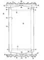
- FIG. 1shows a perspective view of a vertebral body spacer including a main body, a first endplate and a second endplate.
- FIG. 2shows a perspective view of the main body of FIG. 1 with the first and second endplates detached from the main body.
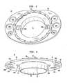
- FIG. 3shows a top view of the first endplate shown in FIG. 1 .
- FIG. 4shows an underside view of the endplate shown in FIG. 3 .
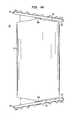
- FIG. 5shows a side elevation view of the vertebral body spacer of FIG. 1 .
- FIG. 6shows a partial cut away view of the vertebral body spacer of FIG. 5 .
- FIG. 7Ashows the first endplate of FIG. 1 under a no-load condition.
- FIG. 7Bshows the first endplate of FIG. 7A under a load condition.
- FIGS. 8A-8Cshow the vertebral body spacer of FIG. 5 with the first and second endplates pivoted to various angles relative to the main body.
- FIG. 1shows a vertebral body spacer in accordance with certain preferred embodiments of the present invention.
- the spacer 20includes a main body 22 having a first endplate 24 secured to an upper end of the main body and a second endplate 26 secured to a lower end of the main body.
- the spacer 20is preferably made of a biocompatible material, such as a polymeric material, titanium, or stainless steel. Preferred materials may also include titanium alloys or stainless steel alloys.
- main body 22has a longitudinal axis designated A—A.
- Main body 22is preferably substantially cylindrical in shape and has an exterior surface that is coaxial with longitudinal axis A—A. In other preferred embodiments, main body 22 may be polygon-shaped in cross section. Main body 22 may have any geometric shape, such as the shape of an oval or ellipse.
- Main body 22preferably has an upper end 28 with a first substantially concave-shaped socket 30 formed therein.
- the upper end 28includes an upper edge 32 that surrounds the first concave socket 30 .
- the upper edge 32includes a first plane 34 and a second plane 36 that are angled relative to one another.
- the planes 34 , 36intersect at respective apexes 38 A and 38 B.
- Upper edge 32also includes opposing first and second retaining clips 40 A and 40 B.
- First retaining clip 40 Ahas an inwardly extending portion 42 A and second retaining clip 40 B has an inwardly extending projection 42 B.
- the retaining clips 40 A, 40 Bare designed to pass through retainer clip openings that extend through the endplates shown in FIG. 1 for securing the endplates to the respective upper and lower ends of main body 22 .
- main body 22also has a lower end 44 including a substantially concave socket 45 and lower edge 46 that is substantially similar in design and shape to the first socket 30 at upper end 28 .
- the lower edge 46has a first inclined plane 48 and a second inclined plane 50 angled relative to one another, the inclined planes intersecting at opposing retaining clips 54 A and 54 B that are designed to pass through the retaining clip apertures of the second endplate.
- Main body 22includes a substantially cylindrical interior wall 53 defining a hollow space 55 that extends between the upper end cavity 30 and the lower end cavity 45 .
- the interior wall 53may be a flat surface or have any geometric shape defining a hollow space inside main body 22 .
- the hollow spaceis adapted to receive bone growth material therein for facilitating fusion of the spacer 20 with vertebral bone.
- FIG. 3shows a top view of the first endplate 24 .
- First endplate 24includes a central opening 56 surrounded by a peripheral flange 58 .
- the peripheral flange 58has an upper surface 60 and a lower surface 62 opposite the upper surface 60 .
- the peripheral flangealso includes a series of apertures 64 A-C and 66 A-C.
- First endplate 24also includes retainer clip apertures 68 A and 68 B that extend between upper and lower surfaces 60 , 62 of flange 58 .
- Upper surface 60also includes a plurality of teeth 70 for anchoring or biting into bone such as the face of a vertebral body.
- first endplate 24also includes a projection 72 extending from the lower surface 62 thereof.
- the projection 72surrounds central opening 56 and has an exterior surface 74 that is substantially curved or convex.
- the substantially convex 74 projectionfacilitates pivotal movement of the first and second endplates 24 , 26 relative to main body 22 (FIG. 1) when the endplates are not under load.
- the vertebral body spacer 20is assembled by juxtaposing the first endplate 24 with the upper end 28 of main body 22 and the second endplate 26 with the lower end 44 of main body 22 .
- the opposing retaining clips 40 A, 40 Bare passed through the retaining clip apertures 68 A, 68 B (FIG. 3) of first endplate 24 .
- the retaining clips 40 A, 40 Bare resilient so as to snap fit in place for pivotally connecting first endplate 24 with main upper end 28 of body 22 .
- the convex exterior surface 74 of projection 72is preferably in close engagement with first socket 30 .
- first endplate 24is able to pivot about apex 38 A, with the engagement of convex exterior surface 74 and first socket 30 guiding movement of first endplate 24 .
- First endplate 24is able to pivot in a counterclockwise direction approximately 10° until the lower surface 62 engages first plane upper edge 34 and in a clockwise direction approximately 10° until the lower surface 62 engages second plane edge 36 .
- the range of pivotal movement of first endplate 24 relative to upper end 28 of main body 22is between 15°-25°.
- second endplate 26is secured to retaining clips 54 A, 54 B at lower end 44 of main body 22 .
- Second endplate 26is assembled with main body 22 by passing retaining clips 54 A, 54 B through retaining clip apertures (not shown) extending between upper surface 60 ′ and underside surface 62 ′.
- convex exterior surface 74 ′ of projection 72 ′closely engages second socket 30 ′ for guiding pivotal movement of second endplate 26 about apex 52 A.
- Second endplateis pivotable approximately 10° in the counterclockwise direction until underside surface 62 ′ engages second plane 50 , and approximately 10° in the clockwise direction until underside surface 62 ′ engages first plane 48 .
- bone growth material(not shown) can be passed through the central openings of the first and second endplates 24 , 26 for being disposed in hollow space 55 .
- the bone growth materialcompletely fills the hollow space 55 and extends beyond the upper and lower ends 28 , 44 of main body 22 .
- the bone growth materialis disposed in the central openings of the endplates 24 , 26 for facilitating fusion with opposing vertebral bodies.
- FIG. 6shows a partially cut-away view of the vertebral body spacer 20 of FIG. 1 .
- main body 22includes upper end 28 and lower end 44 remote therefrom.
- the upper end 28 of main body 22has a first concave socket 30 formed therein and the lower end 44 has a second concave socket 30 ′ formed therein.
- the main body 22is substantially hollow, with the hollow opening extending between first socket 30 and second socket 30 ′.
- FIG. 7Ashows a fragmentary view of FIG. 6 before load is placed upon first endplate 24 .
- first endplate 24Even though convex surface 74 of first endplate 24 is in direct contact with first socket 30 , the first endplate remains free to pivot relative to first socket 30 .
- FIG. 7Bafter load has been placed upon upper surface 60 of first endplate 24 , the convex surface 74 is urged into closer engagement with first socket 30 , thereby locking first endplate 24 in place and preventing further pivotal movement of first endplate 24 relative to main body 22 .
- First endplate 24remains locked from further pivotal movement so long as first endplate remains under load.
- the second endplate 26(FIG. 5) is also locked from further pivotal movement when under load in a manner similar to that described above for the first endplate 24 .
- the above-described locking actioncan be attained without the need for additional parts such as locking screws that are typically required in prior art devices.
- FIGS. 8A-8Cshow the range of pivotal movement of the first and second endplates 24 , 26 relative to main body 22 .
- first endplate 24rotates in a clockwise direction around apex 38 A until underside surface 62 engages second plane 36 .
- Second endplate 26is pivotable about apex 52 A until underside surface 62 ′ engages second plane 50 .
- FIG. 8Bshows the vertebral body spacer 20 of FIG. 8A with first endplate 24 A rotated in a fully clockwise orientation and second endplate 26 positioned equidistant between a fully clockwise rotation and a fully counterclockwise rotation.
- FIG. 8Cshows the vertebral body spacer 20 of FIG. 8B with first endplate 24 fully rotated in a clockwise position and second endplate 26 fully rotated in a clockwise position.
- the vertebral body spacer 20 of the present inventionwill provide an effective spacer between end faces of vertebral bodies.
- the spacer 20 of the present inventionmay span a gap present after one or more discs or vertebral bodies have been removed.
- the teeth 70 of the first and second endplates 24 , 26are designed to bite into the bony end faces of the vertebral bodies for holding the spacer 20 in place.
- a first no-load statewhen no load is applied to the end faces 24 , 26 , the end faces are free to pivot relative to the upper end 28 and lower end 44 of main body 22 .
- endplate 24 , 26Once a load is exerted upon either endplate 24 , 26 , however, the endplates are locked in place from further pivotal movement due to engagement of their convex exterior surfaces 74 , 74 ′ with the respective first and second sockets 30 , 30 ′.
- only one of the ends of the main bodymay have a pivotable endplate connected thereto, while the other end may be rigid or unmovable.
Landscapes
- Health & Medical Sciences (AREA)
- Engineering & Computer Science (AREA)
- Biomedical Technology (AREA)
- Orthopedic Medicine & Surgery (AREA)
- Neurology (AREA)
- Heart & Thoracic Surgery (AREA)
- General Health & Medical Sciences (AREA)
- Transplantation (AREA)
- Cardiology (AREA)
- Vascular Medicine (AREA)
- Life Sciences & Earth Sciences (AREA)
- Animal Behavior & Ethology (AREA)
- Oral & Maxillofacial Surgery (AREA)
- Public Health (AREA)
- Veterinary Medicine (AREA)
- Prostheses (AREA)
- Forklifts And Lifting Vehicles (AREA)
- Soil Working Implements (AREA)
- Joints Allowing Movement (AREA)
Abstract
Description
Claims (33)
Priority Applications (5)
| Application Number | Priority Date | Filing Date | Title |
|---|---|---|---|
| US10/099,693US6808538B2 (en) | 2002-03-15 | 2002-03-15 | Vertebral body spacer having variable wedged endplates |
| DE60302595TDE60302595T2 (en) | 2002-03-15 | 2003-03-13 | Swivel adapter with swiveling end plates |
| EP03290628AEP1346709B1 (en) | 2002-03-15 | 2003-03-13 | Vertebral body spacer having variable wedged endplates |
| AT03290628TATE311837T1 (en) | 2002-03-15 | 2003-03-13 | SWIVEL INTERMEDIATE PIECE WITH SWIVELING END PLATES |
| JP2003071370AJP4050640B2 (en) | 2002-03-15 | 2003-03-17 | Vertebral spacer |
Applications Claiming Priority (1)
| Application Number | Priority Date | Filing Date | Title |
|---|---|---|---|
| US10/099,693US6808538B2 (en) | 2002-03-15 | 2002-03-15 | Vertebral body spacer having variable wedged endplates |
Publications (2)
| Publication Number | Publication Date |
|---|---|
| US20030176925A1 US20030176925A1 (en) | 2003-09-18 |
| US6808538B2true US6808538B2 (en) | 2004-10-26 |
Family
ID=27788324
Family Applications (1)
| Application Number | Title | Priority Date | Filing Date |
|---|---|---|---|
| US10/099,693Expired - LifetimeUS6808538B2 (en) | 2002-03-15 | 2002-03-15 | Vertebral body spacer having variable wedged endplates |
Country Status (5)
| Country | Link |
|---|---|
| US (1) | US6808538B2 (en) |
| EP (1) | EP1346709B1 (en) |
| JP (1) | JP4050640B2 (en) |
| AT (1) | ATE311837T1 (en) |
| DE (1) | DE60302595T2 (en) |
Cited By (61)
| Publication number | Priority date | Publication date | Assignee | Title |
|---|---|---|---|---|
| US20040225360A1 (en)* | 2000-12-14 | 2004-11-11 | Malone David G. | Devices and methods for facilitating controlled bone growth or repair |
| US20040236427A1 (en)* | 2002-03-21 | 2004-11-25 | Berry Bret M. | Vertebral body and disc space replacement devices |
| US20050033435A1 (en)* | 2003-08-04 | 2005-02-10 | Spine Next | Intervertebral disk prosthesis |
| US20050154459A1 (en)* | 2003-10-20 | 2005-07-14 | Howard Wolek | Vertebral body replacement apparatus and method |
| US20050216084A1 (en)* | 2003-04-22 | 2005-09-29 | Fleischmann Lewis W | Collapsible, rotatable, and tiltable hydraulic spinal disc prosthesis system with selectable modular components |
| US20060064168A1 (en)* | 2004-09-23 | 2006-03-23 | Cervitech, Inc. | Prosthesis for bridging a vertebral body |
| US20060064167A1 (en)* | 2004-09-23 | 2006-03-23 | Cervitech, Inc. | Prosthesis for partial replacement of a vertebral body |
| US20060116770A1 (en)* | 2002-03-21 | 2006-06-01 | White John L | Vertebral body and disc space replacement devices |
| US20060200244A1 (en)* | 2003-02-05 | 2006-09-07 | Richard Assaker | Vertebral replacement and distraction device for placing said implant |
| US20060217809A1 (en)* | 2005-03-24 | 2006-09-28 | Accin Corporation | Intervertebral disc replacement device |
| US20070129805A1 (en)* | 2005-12-01 | 2007-06-07 | Braddock Danny H Jr | End device for a vertebral implant |
| US20070250171A1 (en)* | 2006-04-24 | 2007-10-25 | Sdgi Holdings, Inc. | Expandable intervertebral devices and methods of use |
| US20070255413A1 (en)* | 2006-04-27 | 2007-11-01 | Sdgi Holdings, Inc. | Expandable intervertebral spacers and methods of use |
| US20070255415A1 (en)* | 2006-05-01 | 2007-11-01 | Sdgi Holdings, Inc. | Expandable intervertebral spacers and methods of use |
| US20070270960A1 (en)* | 2006-04-24 | 2007-11-22 | Sdgi Holdings, Inc. | Extendable anchor in a vertebral implant and methods of use |
| US20070270964A1 (en)* | 2006-04-27 | 2007-11-22 | Sdgi Holdings, Inc. | Expandable vertebral implant and methods of use |
| US20080021555A1 (en)* | 2006-07-19 | 2008-01-24 | John White | Expandable vertebral body implants and methods of use |
| US20080262621A1 (en)* | 2007-04-17 | 2008-10-23 | K2M, Inc. | I-beam spacer |
| US20090062917A1 (en)* | 2007-08-27 | 2009-03-05 | Foley Kevin T | Spinal interbody replacement devices |
| US20090138088A1 (en)* | 2007-07-03 | 2009-05-28 | Scribner Robert M | Mobile spinal fusion implant |
| US7544208B1 (en) | 2004-05-03 | 2009-06-09 | Theken Spine, Llc | Adjustable corpectomy apparatus |
| US20100016969A1 (en)* | 2007-03-07 | 2010-01-21 | Marcus Richter | Intervertebral implant with elastic part |
| US7815683B2 (en) | 2006-10-16 | 2010-10-19 | Warsaw Orthopedic, Inc. | Implants with helical supports and methods of use for spacing vertebral members |
| US20100305701A1 (en)* | 2005-03-24 | 2010-12-02 | Cardinal Spine, Llc | Spinal implant |
| US20100324685A1 (en)* | 2005-03-24 | 2010-12-23 | Frank Castro | Spinal implant and method of using spinal implant |
| US20100324682A1 (en)* | 2005-03-24 | 2010-12-23 | Frank Castro | Spinal implant |
| WO2010145627A1 (en)* | 2009-06-17 | 2010-12-23 | Ulrich Gmbh & Co. Kg | Implant |
| US20100324686A1 (en)* | 2009-06-17 | 2010-12-23 | Gerner Leonie | Implant |
| US20100324681A1 (en)* | 2005-03-24 | 2010-12-23 | Frank Castro | Wedge-like spinal implant |
| US7918876B2 (en) | 2003-03-24 | 2011-04-05 | Theken Spine, Llc | Spinal implant adjustment device |
| US20110208306A1 (en)* | 2009-11-10 | 2011-08-25 | Zimmer Spine, Inc. | Tissue spacer implant, implant tool, and methods of use thereof |
| US8016886B2 (en) | 2006-07-18 | 2011-09-13 | Altus Partners, Llc | Intervertebral disc replacement device |
| US20120004730A1 (en)* | 2005-03-24 | 2012-01-05 | Cardinal Spine, Llc | End cap and connector for a spinal implant |
| US20120016478A1 (en)* | 2010-07-15 | 2012-01-19 | Warsaw Orthopedic, Inc. | Intervertebral implant with multi-piece end cap |
| US8142435B2 (en) | 2009-02-19 | 2012-03-27 | Aesculap Implant Systems, Llc | Multi-functional surgical instrument and method of use for inserting an implant between two bones |
| US8142441B2 (en) | 2008-10-16 | 2012-03-27 | Aesculap Implant Systems, Llc | Surgical instrument and method of use for inserting an implant between two bones |
| US20120116457A1 (en)* | 2010-11-06 | 2012-05-10 | Limited Liability Company; | Stabilizer for assisting stabilization of a spinal implant and method of using the stabilizer |
| US8182537B2 (en) | 2007-10-30 | 2012-05-22 | Aesculap Implant Systems, Llc | Vertebral body replacement device and method for use to maintain a space between two vertebral bodies within a spine |
| US8211178B2 (en) | 2009-06-18 | 2012-07-03 | Warsaw Orthopedic | Intervertebral implant with a pivoting end cap |
| US8226718B2 (en) | 2005-03-24 | 2012-07-24 | Cardinal Spine, Llc | Spinal implant and method of using spinal implant |
| US20120197400A1 (en)* | 2009-08-06 | 2012-08-02 | Wei Lei | Artificial cervical vertebrae composite joint |
| US8241363B2 (en) | 2007-12-19 | 2012-08-14 | Depuy Spine, Inc. | Expandable corpectomy spinal fusion cage |
| US8241294B2 (en) | 2007-12-19 | 2012-08-14 | Depuy Spine, Inc. | Instruments for expandable corpectomy spinal fusion cage |
| US20120330426A1 (en)* | 2010-04-12 | 2012-12-27 | Mclaughlin Colm | Expandable Vertebral Implant |
| US8377140B2 (en) | 2011-01-12 | 2013-02-19 | Ebi, Llc | Expandable spinal implant device |
| US8454694B2 (en) | 2011-03-03 | 2013-06-04 | Warsaw Orthopedic, Inc. | Interbody device and plate for spinal stabilization and instruments for positioning same |
| US8591587B2 (en) | 2007-10-30 | 2013-11-26 | Aesculap Implant Systems, Llc | Vertebral body replacement device and method for use to maintain a space between two vertebral bodies within a spine |
| US8740980B2 (en) | 2011-01-27 | 2014-06-03 | Warsaw Orthopedic, Inc. | Expandable medical implant |
| US8852280B2 (en) | 2007-09-27 | 2014-10-07 | Warsaw Orthopedic, Inc. | Intervertebral implant |
| US8876905B2 (en) | 2009-04-29 | 2014-11-04 | DePuy Synthes Products, LLC | Minimally invasive corpectomy cage and instrument |
| US8945228B2 (en) | 2012-11-15 | 2015-02-03 | DePuy Synthes Products, LLC | Endplate for a vertebral implant |
| US8992617B2 (en) | 2007-03-13 | 2015-03-31 | DePuy Synthes Products, LLC | Adjustable intervertebral implant |
| US9095444B2 (en) | 2009-07-24 | 2015-08-04 | Warsaw Orthopedic, Inc. | Implant with an interference fit fastener |
| US20160095711A1 (en)* | 2010-07-30 | 2016-04-07 | Igip, Llc | Spacer For Spinal Implant |
| US20160120652A1 (en)* | 2007-03-29 | 2016-05-05 | Life Spine, Inc. | Height adjustable spinal prostheses |
| US9358122B2 (en) | 2011-01-07 | 2016-06-07 | K2M, Inc. | Interbody spacer |
| US9456907B1 (en) | 2005-03-24 | 2016-10-04 | Igip, Llc | Extendable spinal implant |
| US20170065425A1 (en)* | 2015-09-08 | 2017-03-09 | Ulrich Gmbh & Co. Kg | Implant |
| US9700425B1 (en) | 2011-03-20 | 2017-07-11 | Nuvasive, Inc. | Vertebral body replacement and insertion methods |
| US10987229B2 (en)* | 2018-02-14 | 2021-04-27 | Warsaw Orthopedic, Inc. | Spinal implant system |
| US12310855B2 (en) | 2021-09-09 | 2025-05-27 | Warsaw Orthopedic, Inc. | End cap and bone screw for use therewith |
Families Citing this family (83)
| Publication number | Priority date | Publication date | Assignee | Title |
|---|---|---|---|---|
| US7959652B2 (en) | 2005-04-18 | 2011-06-14 | Kyphon Sarl | Interspinous process implant having deployable wings and method of implantation |
| US20080039859A1 (en) | 1997-01-02 | 2008-02-14 | Zucherman James F | Spine distraction implant and method |
| US6068630A (en) | 1997-01-02 | 2000-05-30 | St. Francis Medical Technologies, Inc. | Spine distraction implant |
| US6989032B2 (en)* | 2001-07-16 | 2006-01-24 | Spinecore, Inc. | Artificial intervertebral disc |
| US6673113B2 (en) | 2001-10-18 | 2004-01-06 | Spinecore, Inc. | Intervertebral spacer device having arch shaped spring elements |
| US7223291B2 (en)* | 2001-07-16 | 2007-05-29 | Spinecore, Inc. | Intervertebral spacer device having engagement hole pairs for manipulation using a surgical tool |
| US7169182B2 (en)* | 2001-07-16 | 2007-01-30 | Spinecore, Inc. | Implanting an artificial intervertebral disc |
| US20070198092A1 (en)* | 2001-07-16 | 2007-08-23 | Spinecore, Inc. | System for inserting artificial intervertebral discs |
| US7771477B2 (en) | 2001-10-01 | 2010-08-10 | Spinecore, Inc. | Intervertebral spacer device utilizing a belleville washer having radially spaced concentric grooves |
| US7309358B2 (en)* | 2002-03-21 | 2007-12-18 | Warsaw Orthopedic, Inc. | Vertebral body and disc space replacement devices |
| DE10242329B4 (en) | 2002-09-12 | 2005-03-17 | Biedermann Motech Gmbh | Disc prosthesis |
| DE10242331B4 (en) | 2002-09-12 | 2005-10-20 | Biedermann Motech Gmbh | Placeholder for vertebral bodies or intervertebral discs |
| US7549999B2 (en) | 2003-05-22 | 2009-06-23 | Kyphon Sarl | Interspinous process distraction implant and method of implantation |
| US8147548B2 (en) | 2005-03-21 | 2012-04-03 | Kyphon Sarl | Interspinous process implant having a thread-shaped wing and method of implantation |
| JP4654125B2 (en)* | 2002-10-29 | 2011-03-16 | スパインコア,インコーポレイテッド | Instruments, methods, and functions for use in implanting an artificial disc |
| DE10311477A1 (en)* | 2003-03-15 | 2004-09-23 | Ulrich Gmbh & Co. Kg | Implant to be inserted between the vertebral body of the spine |
| DE202004021289U1 (en) | 2003-05-14 | 2007-06-06 | Kraus, Kilian | Height-adjustable implant for insertion between vertebral bodies and handling tool |
| US7442211B2 (en) | 2003-05-27 | 2008-10-28 | Spinalmotion, Inc. | Intervertebral prosthetic disc |
| US7794465B2 (en)* | 2003-09-10 | 2010-09-14 | Warsaw Orthopedic, Inc. | Artificial spinal discs and associated implantation instruments and methods |
| US7766914B2 (en)* | 2003-09-10 | 2010-08-03 | Warsaw Orthopedic, Inc. | Adjustable drill guide |
| EP1532950B1 (en) | 2003-11-18 | 2008-03-26 | Zimmer GmbH | Spinal disc prosthesis |
| DE10357926B3 (en)* | 2003-12-11 | 2005-09-01 | Deltacor Gmbh | Length adjustable spinal implant |
| GB0401362D0 (en)* | 2004-01-22 | 2004-02-25 | Depuy Int Ltd | Vertebral fusion parts, devices and methods |
| US20080033552A1 (en)* | 2004-05-17 | 2008-02-07 | Canon Kasushiki Kaisha | Sensor Device |
| US8097018B2 (en) | 2005-02-17 | 2012-01-17 | Kyphon Sarl | Percutaneous spinal implants and methods |
| US8100943B2 (en) | 2005-02-17 | 2012-01-24 | Kyphon Sarl | Percutaneous spinal implants and methods |
| US20070276493A1 (en) | 2005-02-17 | 2007-11-29 | Malandain Hugues F | Percutaneous spinal implants and methods |
| US8157841B2 (en) | 2005-02-17 | 2012-04-17 | Kyphon Sarl | Percutaneous spinal implants and methods |
| US8034080B2 (en) | 2005-02-17 | 2011-10-11 | Kyphon Sarl | Percutaneous spinal implants and methods |
| US7811327B2 (en)* | 2005-04-21 | 2010-10-12 | Globus Medical Inc. | Expandable vertebral prosthesis |
| US8585765B2 (en) | 2005-05-06 | 2013-11-19 | Titan Spine, Llc | Endplate-preserving spinal implant having a raised expulsion-resistant edge |
| US8992622B2 (en) | 2005-05-06 | 2015-03-31 | Titan Spine, Llc | Interbody spinal implant having a roughened surface topography |
| US8617248B2 (en) | 2005-05-06 | 2013-12-31 | Titan Spine, Llc | Spinal implant having variable ratios of the integration surface area to the axial passage area |
| US8591590B2 (en) | 2005-05-06 | 2013-11-26 | Titan Spine, Llc | Spinal implant having a transverse aperture |
| US8562684B2 (en)* | 2005-05-06 | 2013-10-22 | Titan Spine, Llc | Endplate-preserving spinal implant with an integration plate having a roughened surface topography |
| US9168147B2 (en) | 2005-05-06 | 2015-10-27 | Titan Spine, Llc | Self-deploying locking screw retention device |
| US9125756B2 (en) | 2005-05-06 | 2015-09-08 | Titan Spine, Llc | Processes for producing regular repeating patterns on surfaces of interbody devices |
| US8814939B2 (en) | 2005-05-06 | 2014-08-26 | Titan Spine, Llc | Implants having three distinct surfaces |
| US8758443B2 (en) | 2005-05-06 | 2014-06-24 | Titan Spine, Llc | Implants with integration surfaces having regular repeating surface patterns |
| US8262737B2 (en) | 2005-05-06 | 2012-09-11 | Titan Spine, Llc | Composite interbody spinal implant having openings of predetermined size and shape |
| US11096796B2 (en) | 2005-05-06 | 2021-08-24 | Titan Spine, Llc | Interbody spinal implant having a roughened surface topography on one or more internal surfaces |
| US8585766B2 (en)* | 2005-05-06 | 2013-11-19 | Titan Spine, Llc | Endplate-preserving spinal implant with an integration plate having durable connectors |
| US8551176B2 (en)* | 2005-05-06 | 2013-10-08 | Titan Spine, Llc | Spinal implant having a passage for enhancing contact between bone graft material and cortical endplate bone |
| US8562685B2 (en) | 2005-05-06 | 2013-10-22 | Titan Spine, Llc | Spinal implant and integration plate for optimizing vertebral endplate contact load-bearing edges |
| US8545568B2 (en) | 2005-05-06 | 2013-10-01 | Titan Spine, Llc | Method of using instruments and interbody spinal implants to enhance distraction |
| US8585767B2 (en)* | 2005-05-06 | 2013-11-19 | Titan Spine, Llc | Endplate-preserving spinal implant with an integration plate having durable connectors |
| US8758442B2 (en) | 2005-05-06 | 2014-06-24 | Titan Spine, Llc | Composite implants having integration surfaces composed of a regular repeating pattern |
| US8435302B2 (en) | 2005-05-06 | 2013-05-07 | Titan Spine, Llc | Instruments and interbody spinal implants enhancing disc space distraction |
| US20120312779A1 (en) | 2005-05-06 | 2012-12-13 | Titian Spine, LLC | Methods for manufacturing implants having integration surfaces |
| DE102005022921B3 (en)* | 2005-05-19 | 2007-01-25 | Aesculap Ag & Co. Kg | Vertebral body replacement implant |
| NZ568985A (en)* | 2005-12-08 | 2010-11-26 | Fbcdevice Aps | Disc implant |
| US8083795B2 (en) | 2006-01-18 | 2011-12-27 | Warsaw Orthopedic, Inc. | Intervertebral prosthetic device for spinal stabilization and method of manufacturing same |
| US8118844B2 (en) | 2006-04-24 | 2012-02-21 | Warsaw Orthopedic, Inc. | Expandable device for insertion between anatomical structures and a procedure utilizing same |
| US8097019B2 (en) | 2006-10-24 | 2012-01-17 | Kyphon Sarl | Systems and methods for in situ assembly of an interspinous process distraction implant |
| FR2908035B1 (en) | 2006-11-08 | 2009-05-01 | Jean Taylor | INTEREPINE IMPLANT |
| US9101410B1 (en)* | 2007-10-24 | 2015-08-11 | Robert E. Urrea | Facet joint fusion device and method for using same |
| US20090198338A1 (en) | 2008-02-04 | 2009-08-06 | Phan Christopher U | Medical implants and methods |
| US8114136B2 (en)* | 2008-03-18 | 2012-02-14 | Warsaw Orthopedic, Inc. | Implants and methods for inter-spinous process dynamic stabilization of a spinal motion segment |
| US8323292B2 (en)* | 2008-12-15 | 2012-12-04 | Spinecore, Inc. | Adjustable pin drill guide and methods therefor |
| US8721723B2 (en) | 2009-01-12 | 2014-05-13 | Globus Medical, Inc. | Expandable vertebral prosthesis |
| US8372117B2 (en) | 2009-06-05 | 2013-02-12 | Kyphon Sarl | Multi-level interspinous implants and methods of use |
| RU2434605C2 (en)* | 2009-06-17 | 2011-11-27 | Ульрих Гмбх Унд Ко. Кг | Implant |
| US8114132B2 (en) | 2010-01-13 | 2012-02-14 | Kyphon Sarl | Dynamic interspinous process device |
| US8317831B2 (en) | 2010-01-13 | 2012-11-27 | Kyphon Sarl | Interspinous process spacer diagnostic balloon catheter and methods of use |
| US8147526B2 (en) | 2010-02-26 | 2012-04-03 | Kyphon Sarl | Interspinous process spacer diagnostic parallel balloon catheter and methods of use |
| US8870880B2 (en) | 2010-04-12 | 2014-10-28 | Globus Medical, Inc. | Angling inserter tool for expandable vertebral implant |
| US8591585B2 (en) | 2010-04-12 | 2013-11-26 | Globus Medical, Inc. | Expandable vertebral implant |
| US20120109302A1 (en)* | 2010-10-27 | 2012-05-03 | Warsaw Orthopedic | Medical implant and method for photodynamic therpy |
| US9468537B2 (en)* | 2011-06-21 | 2016-10-18 | Globus Medical, Inc. | Method and implant device for grafting adjacent vertebral bodies |
| US8425606B2 (en)* | 2011-06-21 | 2013-04-23 | John A. Cowan | Method and implant device for grafting adjacent vertebral bodies |
| US8992619B2 (en) | 2011-11-01 | 2015-03-31 | Titan Spine, Llc | Microstructured implant surfaces |
| US9198764B2 (en) | 2012-01-31 | 2015-12-01 | Blackstone Medical, Inc. | Intervertebral disc prosthesis and method |
| CA2880825C (en) | 2012-03-20 | 2021-03-16 | Titan Spine, Llc | Friction-fit spinal endplate and endplate-preserving method |
| EP2716261A1 (en) | 2012-10-02 | 2014-04-09 | Titan Spine, LLC | Implants with self-deploying anchors |
| US9498349B2 (en) | 2012-10-09 | 2016-11-22 | Titan Spine, Llc | Expandable spinal implant with expansion wedge and anchor |
| US9238319B2 (en)* | 2013-03-14 | 2016-01-19 | DePuy Synthes Products, Inc. | Hybrid intervertebral disc spacer device and method of manufacturing the same |
| ES2923640T3 (en)* | 2013-03-15 | 2022-09-29 | Spectrum Spine Ip Holdings Llc | Expandable Vertebral Body Replacement Device |
| WO2014145982A1 (en)* | 2013-03-15 | 2014-09-18 | Spectrum Spine Ip Holdings, Llc | Expandable vertebral body replacement device, system, and methods |
| US9615935B2 (en) | 2014-01-30 | 2017-04-11 | Titan Spine, Llc | Thermally activated shape memory spring assemblies for implant expansion |
| US9561113B2 (en)* | 2014-12-23 | 2017-02-07 | Globus Medical, Inc. | Vertebral implants and methods for installation thereof |
| EP3288500B1 (en)* | 2015-04-27 | 2021-09-29 | Corenman, Donald, Steven | Biological disc graft and method for relief of lower back pain and joint pain |
| CN106890037A (en)* | 2017-04-10 | 2017-06-27 | 北京大学人民医院 | One kind can extend artificial vertebral body in vivo |
| CN113208785B (en)* | 2021-06-10 | 2022-04-19 | 北京爱康宜诚医疗器材有限公司 | Vertebral prosthesis |
Citations (29)
| Publication number | Priority date | Publication date | Assignee | Title |
|---|---|---|---|---|
| DE248018C (en) | ||||
| DE239523C (en) | ||||
| DE234609C (en) | 1909-04-06 | 1911-05-15 | ||
| DE2263842A1 (en) | 1972-12-28 | 1974-07-04 | Hoffmann Daimler Siegfried Dr | DISC PROTHESIS |
| DE3023353A1 (en) | 1979-10-03 | 1981-04-09 | Gebrüder Sulzer AG, 8401 Winterthur | INTERMEDIATE TURBINE TOTAL PROSTHESIS |
| CH624573A5 (en) | 1978-02-01 | 1981-08-14 | Sulzer Ag | Intervertebral prosthesis |
| US4309777A (en) | 1980-11-13 | 1982-01-12 | Patil Arun A | Artificial intervertebral disc |
| US4759766A (en) | 1984-09-04 | 1988-07-26 | Humboldt-Universitaet Zu Berlin | Intervertebral disc endoprosthesis |
| US4863477A (en) | 1987-05-12 | 1989-09-05 | Monson Gary L | Synthetic intervertebral disc prosthesis |
| US4997432A (en) | 1988-03-23 | 1991-03-05 | Waldemar Link Gmbh & Co. | Surgical instrument set |
| WO1993010725A2 (en) | 1991-12-04 | 1993-06-10 | Customflex Limited | Improvements in or relating to spinal vertebrae implants |
| EP0630625A2 (en) | 1993-06-24 | 1994-12-28 | MAN Ceramics GmbH | Implant for replacing vertebral bodies |
| US5401269A (en)* | 1992-03-13 | 1995-03-28 | Waldemar Link Gmbh & Co. | Intervertebral disc endoprosthesis |
| US5480422A (en) | 1993-07-20 | 1996-01-02 | Biosense, Inc. | Apparatus for treating cardiac arrhythmias |
| US5534029A (en) | 1992-12-14 | 1996-07-09 | Yumiko Shima | Articulated vertebral body spacer |
| US5556431A (en) | 1992-03-13 | 1996-09-17 | B+E,Uml U+Ee Ttner-Janz; Karin | Intervertebral disc endoprosthesis |
| US5562738A (en) | 1992-01-06 | 1996-10-08 | Danek Medical, Inc. | Intervertebral disk arthroplasty device |
| WO1998014142A1 (en) | 1996-10-01 | 1998-04-09 | Surgical Dynamics, Inc. | Spinal fusion implant and method of insertion thereof |
| US5895428A (en)* | 1996-11-01 | 1999-04-20 | Berry; Don | Load bearing spinal joint implant |
| US5899941A (en)* | 1997-12-09 | 1999-05-04 | Chubu Bearing Kabushiki Kaisha | Artificial intervertebral disk |
| WO1999053871A1 (en) | 1998-04-23 | 1999-10-28 | Cauthen Research Group, Inc. | Articulating spinal implant |
| US5989291A (en) | 1998-02-26 | 1999-11-23 | Third Millennium Engineering, Llc | Intervertebral spacer device |
| US6019792A (en) | 1998-04-23 | 2000-02-01 | Cauthen Research Group, Inc. | Articulating spinal implant |
| US6086613A (en)* | 1997-12-23 | 2000-07-11 | Depuy Acromed, Inc. | Spacer assembly for use in spinal surgeries |
| US6156067A (en)* | 1994-11-14 | 2000-12-05 | Spinal Dynamics Corporation | Human spinal disc prosthesis |
| US20010014826A1 (en)* | 1995-02-14 | 2001-08-16 | Lutz Biedermann | Space holder, in particular for a vertebra or an intervertebral disk |
| US6368350B1 (en) | 1999-03-11 | 2002-04-09 | Sulzer Spine-Tech Inc. | Intervertebral disc prosthesis and method |
| US6375681B1 (en)* | 1998-06-23 | 2002-04-23 | Ebi, L.P. | Vertebral body replacement |
| US6682562B2 (en)* | 2000-03-10 | 2004-01-27 | Eurosurgical Sa | Intervertebral disc prosthesis |
- 2002
- 2002-03-15USUS10/099,693patent/US6808538B2/ennot_activeExpired - Lifetime
- 2003
- 2003-03-13DEDE60302595Tpatent/DE60302595T2/ennot_activeExpired - Lifetime
- 2003-03-13EPEP03290628Apatent/EP1346709B1/ennot_activeExpired - Lifetime
- 2003-03-13ATAT03290628Tpatent/ATE311837T1/ennot_activeIP Right Cessation
- 2003-03-17JPJP2003071370Apatent/JP4050640B2/ennot_activeExpired - Fee Related
Patent Citations (33)
| Publication number | Priority date | Publication date | Assignee | Title |
|---|---|---|---|---|
| DE248018C (en) | ||||
| DE239523C (en) | ||||
| DE234609C (en) | 1909-04-06 | 1911-05-15 | ||
| DE2263842A1 (en) | 1972-12-28 | 1974-07-04 | Hoffmann Daimler Siegfried Dr | DISC PROTHESIS |
| CH624573A5 (en) | 1978-02-01 | 1981-08-14 | Sulzer Ag | Intervertebral prosthesis |
| DE3023353A1 (en) | 1979-10-03 | 1981-04-09 | Gebrüder Sulzer AG, 8401 Winterthur | INTERMEDIATE TURBINE TOTAL PROSTHESIS |
| US4309777A (en) | 1980-11-13 | 1982-01-12 | Patil Arun A | Artificial intervertebral disc |
| EP0176728B1 (en) | 1984-09-04 | 1989-07-26 | Humboldt-Universität zu Berlin | Intervertebral-disc prosthesis |
| DE3529761C2 (en) | 1984-09-04 | 1994-06-16 | Buettner Janz Karin | Intervertebral disc prosthesis |
| US4759766A (en) | 1984-09-04 | 1988-07-26 | Humboldt-Universitaet Zu Berlin | Intervertebral disc endoprosthesis |
| US4863477A (en) | 1987-05-12 | 1989-09-05 | Monson Gary L | Synthetic intervertebral disc prosthesis |
| US4997432A (en) | 1988-03-23 | 1991-03-05 | Waldemar Link Gmbh & Co. | Surgical instrument set |
| WO1993010725A2 (en) | 1991-12-04 | 1993-06-10 | Customflex Limited | Improvements in or relating to spinal vertebrae implants |
| US5562738A (en) | 1992-01-06 | 1996-10-08 | Danek Medical, Inc. | Intervertebral disk arthroplasty device |
| US5401269A (en)* | 1992-03-13 | 1995-03-28 | Waldemar Link Gmbh & Co. | Intervertebral disc endoprosthesis |
| US5556431A (en) | 1992-03-13 | 1996-09-17 | B+E,Uml U+Ee Ttner-Janz; Karin | Intervertebral disc endoprosthesis |
| US5534029A (en) | 1992-12-14 | 1996-07-09 | Yumiko Shima | Articulated vertebral body spacer |
| EP0630625A2 (en) | 1993-06-24 | 1994-12-28 | MAN Ceramics GmbH | Implant for replacing vertebral bodies |
| DE4417629A1 (en) | 1993-06-24 | 1995-01-05 | Man Ceramics Gmbh | Implant for the replacement of vertebral bodies |
| US5480422A (en) | 1993-07-20 | 1996-01-02 | Biosense, Inc. | Apparatus for treating cardiac arrhythmias |
| US6156067A (en)* | 1994-11-14 | 2000-12-05 | Spinal Dynamics Corporation | Human spinal disc prosthesis |
| US20010014826A1 (en)* | 1995-02-14 | 2001-08-16 | Lutz Biedermann | Space holder, in particular for a vertebra or an intervertebral disk |
| WO1998014142A1 (en) | 1996-10-01 | 1998-04-09 | Surgical Dynamics, Inc. | Spinal fusion implant and method of insertion thereof |
| US5895428A (en)* | 1996-11-01 | 1999-04-20 | Berry; Don | Load bearing spinal joint implant |
| US5899941A (en)* | 1997-12-09 | 1999-05-04 | Chubu Bearing Kabushiki Kaisha | Artificial intervertebral disk |
| US6086613A (en)* | 1997-12-23 | 2000-07-11 | Depuy Acromed, Inc. | Spacer assembly for use in spinal surgeries |
| US5989291A (en) | 1998-02-26 | 1999-11-23 | Third Millennium Engineering, Llc | Intervertebral spacer device |
| US6019792A (en) | 1998-04-23 | 2000-02-01 | Cauthen Research Group, Inc. | Articulating spinal implant |
| US6179874B1 (en) | 1998-04-23 | 2001-01-30 | Cauthen Research Group, Inc. | Articulating spinal implant |
| WO1999053871A1 (en) | 1998-04-23 | 1999-10-28 | Cauthen Research Group, Inc. | Articulating spinal implant |
| US6375681B1 (en)* | 1998-06-23 | 2002-04-23 | Ebi, L.P. | Vertebral body replacement |
| US6368350B1 (en) | 1999-03-11 | 2002-04-09 | Sulzer Spine-Tech Inc. | Intervertebral disc prosthesis and method |
| US6682562B2 (en)* | 2000-03-10 | 2004-01-27 | Eurosurgical Sa | Intervertebral disc prosthesis |
Cited By (135)
| Publication number | Priority date | Publication date | Assignee | Title |
|---|---|---|---|---|
| US8906093B2 (en) | 2000-12-14 | 2014-12-09 | DePuy Synthes Products, LLC | Devices and methods for facilitating controlled bone growth or repair |
| US7837735B2 (en)* | 2000-12-14 | 2010-11-23 | Depuy Spine, Inc. | Devices and methods for facilitating controlled bone growth or repair |
| US8142503B2 (en) | 2000-12-14 | 2012-03-27 | Depuy Spine, Inc. | Devices and methods for facilitating controlled bone growth or repair |
| US20040225360A1 (en)* | 2000-12-14 | 2004-11-11 | Malone David G. | Devices and methods for facilitating controlled bone growth or repair |
| US8523908B2 (en) | 2000-12-14 | 2013-09-03 | Depuy Synthes Products Llc | Devices and methods for facilitating controlled bone growth or repair |
| US8617246B2 (en) | 2000-12-14 | 2013-12-31 | Depuy Spine, Inc. | Devices and methods for facilitating controlled bone growth or repair |
| US20060116770A1 (en)* | 2002-03-21 | 2006-06-01 | White John L | Vertebral body and disc space replacement devices |
| US20040236427A1 (en)* | 2002-03-21 | 2004-11-25 | Berry Bret M. | Vertebral body and disc space replacement devices |
| US7887594B2 (en) | 2002-03-21 | 2011-02-15 | Warsaw Orthopedic, Inc. | Vertebral body and disc space replacement devices |
| US8512406B2 (en) | 2002-03-21 | 2013-08-20 | Warsaw Orthopedic, Inc. | Vertebral body and disc space replacement devices |
| US20100004752A1 (en)* | 2002-03-21 | 2010-01-07 | White John L | Vertebral body and disc space replacement devices |
| US7615078B2 (en)* | 2002-03-21 | 2009-11-10 | Warsaw Orthopedic, Inc. | Vertebral body and disc space replacement devices |
| US20060200244A1 (en)* | 2003-02-05 | 2006-09-07 | Richard Assaker | Vertebral replacement and distraction device for placing said implant |
| US7819920B2 (en)* | 2003-02-05 | 2010-10-26 | Alphatec Spine, Inc. | Vertebral replacement and distraction device for placing said implant |
| US8152851B2 (en) | 2003-03-24 | 2012-04-10 | Theken Spine, Llc | Expandable corpectomy device |
| US7918876B2 (en) | 2003-03-24 | 2011-04-05 | Theken Spine, Llc | Spinal implant adjustment device |
| US20050216084A1 (en)* | 2003-04-22 | 2005-09-29 | Fleischmann Lewis W | Collapsible, rotatable, and tiltable hydraulic spinal disc prosthesis system with selectable modular components |
| US7419505B2 (en) | 2003-04-22 | 2008-09-02 | Fleischmann Lewis W | Collapsible, rotatable, and tiltable hydraulic spinal disc prosthesis system with selectable modular components |
| US20050033435A1 (en)* | 2003-08-04 | 2005-02-10 | Spine Next | Intervertebral disk prosthesis |
| US7611538B2 (en)* | 2003-08-04 | 2009-11-03 | Zimmer Spine S.A.S. | Intervertebral disk prosthesis |
| US8226721B2 (en) | 2003-08-04 | 2012-07-24 | Zimmer Spine S.A.S. | Method of implanting intervertebral disk prosthesis |
| US7896919B2 (en) | 2003-08-04 | 2011-03-01 | Zimmer Spine S.A.S. | Method of implanting intervertebral disk prosthesis |
| US20050154459A1 (en)* | 2003-10-20 | 2005-07-14 | Howard Wolek | Vertebral body replacement apparatus and method |
| US7776093B2 (en)* | 2003-10-20 | 2010-08-17 | Blackstone Medical, Inc. | Vertebral body replacement apparatus and method |
| US7544208B1 (en) | 2004-05-03 | 2009-06-09 | Theken Spine, Llc | Adjustable corpectomy apparatus |
| US8192493B2 (en) | 2004-09-23 | 2012-06-05 | Cervitech, Inc. | Prosthesis for bridging a vertebral body |
| US8070812B2 (en)* | 2004-09-23 | 2011-12-06 | Cervitech, Inc. | Prosthesis for partial replacement of a vertebral body |
| US8409285B2 (en) | 2004-09-23 | 2013-04-02 | Cervitech, Inc. | Prosthesis for partial replacement of a vertebral body |
| US20060064168A1 (en)* | 2004-09-23 | 2006-03-23 | Cervitech, Inc. | Prosthesis for bridging a vertebral body |
| US20100131066A1 (en)* | 2004-09-23 | 2010-05-27 | Cervitech, Inc. | Prosthesis for bridging a vertebral body |
| US20060064167A1 (en)* | 2004-09-23 | 2006-03-23 | Cervitech, Inc. | Prosthesis for partial replacement of a vertebral body |
| US8226718B2 (en) | 2005-03-24 | 2012-07-24 | Cardinal Spine, Llc | Spinal implant and method of using spinal implant |
| US20120004730A1 (en)* | 2005-03-24 | 2012-01-05 | Cardinal Spine, Llc | End cap and connector for a spinal implant |
| US8673006B2 (en) | 2005-03-24 | 2014-03-18 | Igip, Llc | Spinal implant |
| US7753957B2 (en) | 2005-03-24 | 2010-07-13 | Accelerated Innovation, Llc | Ball and Socket intervertebral disc replacement device with keyed surfaces assembly |
| US20100305701A1 (en)* | 2005-03-24 | 2010-12-02 | Cardinal Spine, Llc | Spinal implant |
| US20100324685A1 (en)* | 2005-03-24 | 2010-12-23 | Frank Castro | Spinal implant and method of using spinal implant |
| US20100324682A1 (en)* | 2005-03-24 | 2010-12-23 | Frank Castro | Spinal implant |
| US20140358234A1 (en)* | 2005-03-24 | 2014-12-04 | Frank P. Castro | End Cap And Connector For A Spinal Implant |
| US9456907B1 (en) | 2005-03-24 | 2016-10-04 | Igip, Llc | Extendable spinal implant |
| US20100324681A1 (en)* | 2005-03-24 | 2010-12-23 | Frank Castro | Wedge-like spinal implant |
| US20100324678A1 (en)* | 2005-03-24 | 2010-12-23 | Frank Castro | Spinal implant and method of using spinal implant |
| US8246683B2 (en) | 2005-03-24 | 2012-08-21 | Cardinal Spine, Llc | Spinal implant |
| US20060217809A1 (en)* | 2005-03-24 | 2006-09-28 | Accin Corporation | Intervertebral disc replacement device |
| US8986383B2 (en)* | 2005-03-24 | 2015-03-24 | Igip, Llc | End cap and connector for a spinal implant |
| US8361149B2 (en) | 2005-03-24 | 2013-01-29 | Cardinal Spine, Llc | Wedge-like spinal implant |
| US8002832B2 (en) | 2005-03-24 | 2011-08-23 | Cardinal Spine, Llc | Spinal implant and method of using spinal implant |
| US7942932B2 (en) | 2005-03-24 | 2011-05-17 | Cardinal Spine, Llc | Spinal implant and method of using spinal implant |
| US9259323B2 (en)* | 2005-03-24 | 2016-02-16 | Igip, Llc | End cap and connector for a spinal implant |
| US20070129805A1 (en)* | 2005-12-01 | 2007-06-07 | Braddock Danny H Jr | End device for a vertebral implant |
| US7621953B2 (en)* | 2005-12-01 | 2009-11-24 | Warsaw Orthopedic, Inc. | End device for a vertebral implant |
| US8657882B2 (en) | 2006-04-24 | 2014-02-25 | Warsaw Orthopedic, Inc. | Expandable intervertebral devices and methods of use |
| US20070270960A1 (en)* | 2006-04-24 | 2007-11-22 | Sdgi Holdings, Inc. | Extendable anchor in a vertebral implant and methods of use |
| US20070250171A1 (en)* | 2006-04-24 | 2007-10-25 | Sdgi Holdings, Inc. | Expandable intervertebral devices and methods of use |
| US20070270964A1 (en)* | 2006-04-27 | 2007-11-22 | Sdgi Holdings, Inc. | Expandable vertebral implant and methods of use |
| US20070255413A1 (en)* | 2006-04-27 | 2007-11-01 | Sdgi Holdings, Inc. | Expandable intervertebral spacers and methods of use |
| US7794501B2 (en) | 2006-04-27 | 2010-09-14 | Wasaw Orthopedic, Inc. | Expandable intervertebral spacers and methods of use |
| US8187331B2 (en) | 2006-04-27 | 2012-05-29 | Warsaw Orthopedic, Inc. | Expandable vertebral implant and methods of use |
| US7708779B2 (en) | 2006-05-01 | 2010-05-04 | Warsaw Orthopedic, Inc. | Expandable intervertebral spacers and methods of use |
| US8579979B2 (en) | 2006-05-01 | 2013-11-12 | Warsaw Orthopedic, Inc. | Expandable intervertebral spacers and methods of use |
| US20070255415A1 (en)* | 2006-05-01 | 2007-11-01 | Sdgi Holdings, Inc. | Expandable intervertebral spacers and methods of use |
| US8016886B2 (en) | 2006-07-18 | 2011-09-13 | Altus Partners, Llc | Intervertebral disc replacement device |
| US20080021555A1 (en)* | 2006-07-19 | 2008-01-24 | John White | Expandable vertebral body implants and methods of use |
| US7862618B2 (en) | 2006-07-19 | 2011-01-04 | Warsaw Orthopedic, Inc. | Expandable vertebral body implants and methods of use |
| US7815683B2 (en) | 2006-10-16 | 2010-10-19 | Warsaw Orthopedic, Inc. | Implants with helical supports and methods of use for spacing vertebral members |
| US9034039B2 (en)* | 2007-03-07 | 2015-05-19 | Ulrich Gmbh & Co.Kg | Intervertebral implant with elastic part |
| US20100016969A1 (en)* | 2007-03-07 | 2010-01-21 | Marcus Richter | Intervertebral implant with elastic part |
| US8992617B2 (en) | 2007-03-13 | 2015-03-31 | DePuy Synthes Products, LLC | Adjustable intervertebral implant |
| US20160120652A1 (en)* | 2007-03-29 | 2016-05-05 | Life Spine, Inc. | Height adjustable spinal prostheses |
| US10052210B2 (en)* | 2007-03-29 | 2018-08-21 | Life Spine, Inc. | Height adjustable spinal prostheses |
| US20080262621A1 (en)* | 2007-04-17 | 2008-10-23 | K2M, Inc. | I-beam spacer |
| US20090138088A1 (en)* | 2007-07-03 | 2009-05-28 | Scribner Robert M | Mobile spinal fusion implant |
| US20090062917A1 (en)* | 2007-08-27 | 2009-03-05 | Foley Kevin T | Spinal interbody replacement devices |
| USRE48058E1 (en) | 2007-09-27 | 2020-06-23 | Warsaw Orthopedic, Inc. | Intervertebral implant |
| US8852280B2 (en) | 2007-09-27 | 2014-10-07 | Warsaw Orthopedic, Inc. | Intervertebral implant |
| US10201432B2 (en) | 2007-10-30 | 2019-02-12 | Aesculap Implant Systems, Llc | Vertebral body replacement device and method for use to maintain a space between two vertebral bodies within a spine |
| US8182537B2 (en) | 2007-10-30 | 2012-05-22 | Aesculap Implant Systems, Llc | Vertebral body replacement device and method for use to maintain a space between two vertebral bodies within a spine |
| US10881527B2 (en) | 2007-10-30 | 2021-01-05 | Aesculap Implant Systems, Llc | Vertebral body replacement device and method for use to maintain a space between two vertebral bodies within a spine |
| US10806595B2 (en) | 2007-10-30 | 2020-10-20 | Aesculap Implant Systems, Llc | Vertebral body replacement device and method for use to maintain a space between two vertebral bodies within a spine |
| US8591587B2 (en) | 2007-10-30 | 2013-11-26 | Aesculap Implant Systems, Llc | Vertebral body replacement device and method for use to maintain a space between two vertebral bodies within a spine |
| US8690950B2 (en) | 2007-10-30 | 2014-04-08 | Aesculap Implant Systems, Llc | Vertebral body replacement device and method for use to maintain a space between two vertebral bodies within a spine |
| US9034046B2 (en) | 2007-10-30 | 2015-05-19 | Aesculap Implant Systems, Llc | Vertebral body replacement device and method for use to maintain a space between two vertebral bodies within a spine |
| USRE46261E1 (en) | 2007-12-19 | 2017-01-03 | DePuy Synthes Products, Inc. | Instruments for expandable corpectomy spinal fusion cage |
| US8241294B2 (en) | 2007-12-19 | 2012-08-14 | Depuy Spine, Inc. | Instruments for expandable corpectomy spinal fusion cage |
| US8241363B2 (en) | 2007-12-19 | 2012-08-14 | Depuy Spine, Inc. | Expandable corpectomy spinal fusion cage |
| US8702719B2 (en)* | 2008-10-16 | 2014-04-22 | Aesculap Implant Systems, Llc | Surgical instrument and method of use for inserting an implant between two bones |
| US8142441B2 (en) | 2008-10-16 | 2012-03-27 | Aesculap Implant Systems, Llc | Surgical instrument and method of use for inserting an implant between two bones |
| US8142435B2 (en) | 2009-02-19 | 2012-03-27 | Aesculap Implant Systems, Llc | Multi-functional surgical instrument and method of use for inserting an implant between two bones |
| US8876905B2 (en) | 2009-04-29 | 2014-11-04 | DePuy Synthes Products, LLC | Minimally invasive corpectomy cage and instrument |
| US8202321B2 (en) | 2009-06-17 | 2012-06-19 | Ulrich Gmbh & Co. Kg | Implant |
| CN102123684A (en)* | 2009-06-17 | 2011-07-13 | 乌尔里克两合公司 | implant |
| WO2010145627A1 (en)* | 2009-06-17 | 2010-12-23 | Ulrich Gmbh & Co. Kg | Implant |
| US20100324686A1 (en)* | 2009-06-17 | 2010-12-23 | Gerner Leonie | Implant |
| US8211178B2 (en) | 2009-06-18 | 2012-07-03 | Warsaw Orthopedic | Intervertebral implant with a pivoting end cap |
| US9433453B2 (en) | 2009-07-24 | 2016-09-06 | Warsaw Orthopedic, Inc. | Implant with an interference fit fastener |
| US9095444B2 (en) | 2009-07-24 | 2015-08-04 | Warsaw Orthopedic, Inc. | Implant with an interference fit fastener |
| US8613770B2 (en)* | 2009-08-06 | 2013-12-24 | Wei Lei et al. | Artificial cervical vertebrae composite joint |
| US20120197400A1 (en)* | 2009-08-06 | 2012-08-02 | Wei Lei | Artificial cervical vertebrae composite joint |
| WO2011028236A1 (en)* | 2009-08-27 | 2011-03-10 | Cardinal Spine, Llc | Spinal implant |
| US10092410B2 (en)* | 2009-11-10 | 2018-10-09 | Medivest, Llc | Methods of using a vertebral body replacement device |
| US20110208306A1 (en)* | 2009-11-10 | 2011-08-25 | Zimmer Spine, Inc. | Tissue spacer implant, implant tool, and methods of use thereof |
| US9295559B2 (en)* | 2009-11-10 | 2016-03-29 | Medivest, Llc | Tissue spacer implant |
| US20160317314A1 (en)* | 2009-11-10 | 2016-11-03 | Medivest, Llc | Tissue spacer implant, implant tool, and methods of use thereof |
| US9808349B2 (en)* | 2010-04-12 | 2017-11-07 | Globus Medical Inc | Expandable vertebral implant |
| US20120330426A1 (en)* | 2010-04-12 | 2012-12-27 | Mclaughlin Colm | Expandable Vertebral Implant |
| US20120016478A1 (en)* | 2010-07-15 | 2012-01-19 | Warsaw Orthopedic, Inc. | Intervertebral implant with multi-piece end cap |
| US10016279B1 (en) | 2010-07-30 | 2018-07-10 | K2M, Inc. | Spacer for spinal implant |
| US20160095711A1 (en)* | 2010-07-30 | 2016-04-07 | Igip, Llc | Spacer For Spinal Implant |
| US9402734B2 (en)* | 2010-07-30 | 2016-08-02 | Igip, Llc | Spacer for spinal implant |
| US20120116457A1 (en)* | 2010-11-06 | 2012-05-10 | Limited Liability Company; | Stabilizer for assisting stabilization of a spinal implant and method of using the stabilizer |
| US9358122B2 (en) | 2011-01-07 | 2016-06-07 | K2M, Inc. | Interbody spacer |
| US9050195B2 (en) | 2011-01-12 | 2015-06-09 | Ebi, Llc | Expandable spinal implant device |
| US8377140B2 (en) | 2011-01-12 | 2013-02-19 | Ebi, Llc | Expandable spinal implant device |
| US8740980B2 (en) | 2011-01-27 | 2014-06-03 | Warsaw Orthopedic, Inc. | Expandable medical implant |
| US8801788B2 (en) | 2011-01-27 | 2014-08-12 | Warsaw Orthopedic, Inc. | Expandable medical implant |
| US9615940B2 (en) | 2011-03-03 | 2017-04-11 | Warsaw Orthopedic, Inc. | Interbody device and plate for spinal stabilization and instruments for positioning same |
| US8690948B2 (en) | 2011-03-03 | 2014-04-08 | Warsaw Orthopedic, Inc. | Interbody device and plate for spinal stabilization and instruments for positioning same |
| US9925063B2 (en) | 2011-03-03 | 2018-03-27 | Warsaw Orthopedic, Inc. | Interbody device and plate for spinal stabilization and instruments for positioning same |
| US9180019B2 (en) | 2011-03-03 | 2015-11-10 | Warsaw Orthopedic, Inc. | Interbody device and plate for spinal stabilization and instruments for positioning same |
| US8454694B2 (en) | 2011-03-03 | 2013-06-04 | Warsaw Orthopedic, Inc. | Interbody device and plate for spinal stabilization and instruments for positioning same |
| US9526532B2 (en) | 2011-03-03 | 2016-12-27 | Warsaw Orthopedic, Inc. | Interbody device and plate for spinal stabilization and instruments for positioning same |
| US12186198B2 (en) | 2011-03-20 | 2025-01-07 | Nuvasive, Inc. | Vertebral body replacement and insertion methods |
| US9700425B1 (en) | 2011-03-20 | 2017-07-11 | Nuvasive, Inc. | Vertebral body replacement and insertion methods |
| US11389301B2 (en) | 2011-03-20 | 2022-07-19 | Nuvasive, Inc. | Vertebral body replacement and insertion methods |
| US10485672B2 (en) | 2011-03-20 | 2019-11-26 | Nuvasive, Inc. | Vertebral body replacement and insertion methods |
| US8945228B2 (en) | 2012-11-15 | 2015-02-03 | DePuy Synthes Products, LLC | Endplate for a vertebral implant |
| US20170065425A1 (en)* | 2015-09-08 | 2017-03-09 | Ulrich Gmbh & Co. Kg | Implant |
| CN106491248B (en)* | 2015-09-08 | 2019-11-01 | 乌尔里克两合公司 | Implantation material |
| US10226352B2 (en)* | 2015-09-08 | 2019-03-12 | Ulrich Gmbh & Co. Kg | Implant |
| CN106491248A (en)* | 2015-09-08 | 2017-03-15 | 乌尔里克两合公司 | Implant |
| US10987229B2 (en)* | 2018-02-14 | 2021-04-27 | Warsaw Orthopedic, Inc. | Spinal implant system |
| US11701237B2 (en) | 2018-02-14 | 2023-07-18 | Warsaw Orthopedic, Inc. | Spinal implant system |
| US20230240859A1 (en)* | 2018-02-14 | 2023-08-03 | Warsaw Orthopedic, Inc. | Spinal implant system |
| US11992420B2 (en)* | 2018-02-14 | 2024-05-28 | Warsaw Orthopedic, Inc. | Spinal implant system |
| US12310855B2 (en) | 2021-09-09 | 2025-05-27 | Warsaw Orthopedic, Inc. | End cap and bone screw for use therewith |
Also Published As
| Publication number | Publication date |
|---|---|
| EP1346709B1 (en) | 2005-12-07 |
| DE60302595D1 (en) | 2006-01-12 |
| EP1346709A2 (en) | 2003-09-24 |
| JP4050640B2 (en) | 2008-02-20 |
| EP1346709A3 (en) | 2003-11-19 |
| DE60302595T2 (en) | 2006-08-24 |
| US20030176925A1 (en) | 2003-09-18 |
| JP2003305068A (en) | 2003-10-28 |
| ATE311837T1 (en) | 2005-12-15 |
Similar Documents
| Publication | Publication Date | Title |
|---|---|---|
| US6808538B2 (en) | Vertebral body spacer having variable wedged endplates | |
| US7141070B2 (en) | Intervertebral spacer device having a domed arch shaped spring | |
| US8753399B2 (en) | Dynamic interbody device | |
| US6770095B2 (en) | Intervertebral disc | |
| US6179874B1 (en) | Articulating spinal implant | |
| US8562682B2 (en) | Artificial intervertebral joint permitting translational and rotational motion | |
| US6440168B1 (en) | Articulating spinal implant | |
| US8979852B2 (en) | Tools for implantation of interspinous implants and methods therof | |
| US9060871B2 (en) | Total disc replacement device | |
| US20020099443A1 (en) | End member for a bone fusion implant | |
| US20060149378A1 (en) | Articulating spinal disc prosthetic | |
| US20080065211A1 (en) | Intervertebral disc replacement device | |
| US20060111783A1 (en) | Articulating spinal disc prosthetic | |
| KR101889365B1 (en) | Structure of plate hybrid cage | |
| CA2360871C (en) | End member for a bone fusion implant | |
| EP3993740B1 (en) | Intervertebral implant for quadrupeds | |
| CA2617889C (en) | End member for a bone fusion implant |
Legal Events
| Date | Code | Title | Description |
|---|---|---|---|
| AS | Assignment | Owner name:STRYKER SPINE, FRANCE Free format text:ASSIGNMENT OF ASSIGNORS INTEREST;ASSIGNOR:PAPONNEAU, FRANCOIS;REEL/FRAME:013013/0291 Effective date:20020521 | |
| STCF | Information on status: patent grant | Free format text:PATENTED CASE | |
| CC | Certificate of correction | ||
| FPAY | Fee payment | Year of fee payment:4 | |
| FPAY | Fee payment | Year of fee payment:8 | |
| AS | Assignment | Owner name:STRYKER EUROPEAN HOLDINGS I, LLC, MICHIGAN Free format text:NUNC PRO TUNC ASSIGNMENT;ASSIGNOR:STRYKER EUROPEAN HOLDINGS VI, LLC;REEL/FRAME:037153/0391 Effective date:20151008 Owner name:STRYKER EUROPEAN HOLDINGS VI, LLC, MICHIGAN Free format text:NUNC PRO TUNC ASSIGNMENT;ASSIGNOR:STRYKER SPINE SAS;REEL/FRAME:037152/0825 Effective date:20151008 | |
| FPAY | Fee payment | Year of fee payment:12 | |
| AS | Assignment | Owner name:STRYKER EUROPEAN OPERATIONS HOLDINGS LLC, MICHIGAN Free format text:CHANGE OF NAME;ASSIGNOR:STRYKER EUROPEAN HOLDINGS III, LLC;REEL/FRAME:052860/0716 Effective date:20190226 Owner name:STRYKER EUROPEAN HOLDINGS III, LLC, DELAWARE Free format text:NUNC PRO TUNC ASSIGNMENT;ASSIGNOR:STRYKER EUROPEAN HOLDINGS I, LLC;REEL/FRAME:052861/0001 Effective date:20200519 |