US6807230B2 - Broadcast encoding system and method - Google Patents
Broadcast encoding system and methodDownload PDFInfo
- Publication number
- US6807230B2 US6807230B2US10/444,409US44440903AUS6807230B2US 6807230 B2US6807230 B2US 6807230B2US 44440903 AUS44440903 AUS 44440903AUS 6807230 B2US6807230 B2US 6807230B2
- Authority
- US
- United States
- Prior art keywords
- frequency
- code
- block
- signal
- audio
- Prior art date
- Legal status (The legal status is an assumption and is not a legal conclusion. Google has not performed a legal analysis and makes no representation as to the accuracy of the status listed.)
- Expired - Lifetime
Links
- 238000000034methodMethods0.000titleclaimsdescription30
- 238000012360testing methodMethods0.000claimsdescription7
- 230000001419dependent effectEffects0.000claims1
- 230000003595spectral effectEffects0.000abstractdescription79
- 230000003247decreasing effectEffects0.000abstractdescription3
- 230000005236sound signalEffects0.000description43
- 238000012545processingMethods0.000description36
- 238000001228spectrumMethods0.000description21
- 239000000872bufferSubstances0.000description18
- 238000007906compressionMethods0.000description15
- 238000005070samplingMethods0.000description15
- 230000006835compressionEffects0.000description14
- 238000013459approachMethods0.000description13
- 230000006870functionEffects0.000description12
- 230000000873masking effectEffects0.000description10
- 238000012986modificationMethods0.000description10
- 230000004048modificationEffects0.000description10
- 238000004458analytical methodMethods0.000description9
- 230000000694effectsEffects0.000description5
- 238000005259measurementMethods0.000description5
- 230000002238attenuated effectEffects0.000description4
- 230000008859changeEffects0.000description4
- 238000012937correctionMethods0.000description4
- 238000009826distributionMethods0.000description4
- 230000008569processEffects0.000description4
- 230000001360synchronised effectEffects0.000description4
- ULFUTCYGWMQVIO-PCVRPHSVSA-N[(6s,8r,9s,10r,13s,14s,17r)-17-acetyl-6,10,13-trimethyl-3-oxo-2,6,7,8,9,11,12,14,15,16-decahydro-1h-cyclopenta[a]phenanthren-17-yl] acetate;[(8r,9s,13s,14s,17s)-3-hydroxy-13-methyl-6,7,8,9,11,12,14,15,16,17-decahydrocyclopenta[a]phenanthren-17-yl] pentanoChemical compoundC1CC2=CC(O)=CC=C2[C@@H]2[C@@H]1[C@@H]1CC[C@H](OC(=O)CCCC)[C@@]1(C)CC2.C([C@@]12C)CC(=O)C=C1[C@@H](C)C[C@@H]1[C@@H]2CC[C@]2(C)[C@@](OC(C)=O)(C(C)=O)CC[C@H]21ULFUTCYGWMQVIO-PCVRPHSVSA-N0.000description3
- 230000003321amplificationEffects0.000description2
- 230000008901benefitEffects0.000description2
- 230000006837decompressionEffects0.000description2
- 238000013461designMethods0.000description2
- 238000001514detection methodMethods0.000description2
- 238000010586diagramMethods0.000description2
- 238000003199nucleic acid amplification methodMethods0.000description2
- 230000007704transitionEffects0.000description2
- JCLFHZLOKITRCE-UHFFFAOYSA-N4-pentoxyphenolChemical compoundCCCCCOC1=CC=C(O)C=C1JCLFHZLOKITRCE-UHFFFAOYSA-N0.000description1
- 101100083446Danio rerio plekhh1 geneProteins0.000description1
- 238000004364calculation methodMethods0.000description1
- 230000000295complement effectEffects0.000description1
- 230000001143conditioned effectEffects0.000description1
- 230000001934delayEffects0.000description1
- 238000005516engineering processMethods0.000description1
- 238000012806monitoring deviceMethods0.000description1
- 238000012544monitoring processMethods0.000description1
- 230000010363phase shiftEffects0.000description1
- 238000011084recoveryMethods0.000description1
- 230000002829reductive effectEffects0.000description1
- 230000035945sensitivityEffects0.000description1
- 230000008054signal transmissionEffects0.000description1
- 238000010183spectrum analysisMethods0.000description1
- 230000003068static effectEffects0.000description1
- 230000001052transient effectEffects0.000description1
Images


Classifications
- H—ELECTRICITY
- H04—ELECTRIC COMMUNICATION TECHNIQUE
- H04H—BROADCAST COMMUNICATION
- H04H20/00—Arrangements for broadcast or for distribution combined with broadcast
- H04H20/28—Arrangements for simultaneous broadcast of plural pieces of information
- H04H20/30—Arrangements for simultaneous broadcast of plural pieces of information by a single channel
- H04H20/31—Arrangements for simultaneous broadcast of plural pieces of information by a single channel using in-band signals, e.g. subsonic or cue signal
- H—ELECTRICITY
- H04—ELECTRIC COMMUNICATION TECHNIQUE
- H04H—BROADCAST COMMUNICATION
- H04H20/00—Arrangements for broadcast or for distribution combined with broadcast
- H04H20/28—Arrangements for simultaneous broadcast of plural pieces of information
- H04H20/33—Arrangements for simultaneous broadcast of plural pieces of information by plural channels
- H—ELECTRICITY
- H04—ELECTRIC COMMUNICATION TECHNIQUE
- H04H—BROADCAST COMMUNICATION
- H04H60/00—Arrangements for broadcast applications with a direct linking to broadcast information or broadcast space-time; Broadcast-related systems
- H04H60/35—Arrangements for identifying or recognising characteristics with a direct linkage to broadcast information or to broadcast space-time, e.g. for identifying broadcast stations or for identifying users
- H04H60/38—Arrangements for identifying or recognising characteristics with a direct linkage to broadcast information or to broadcast space-time, e.g. for identifying broadcast stations or for identifying users for identifying broadcast time or space
- H04H60/39—Arrangements for identifying or recognising characteristics with a direct linkage to broadcast information or to broadcast space-time, e.g. for identifying broadcast stations or for identifying users for identifying broadcast time or space for identifying broadcast space-time
- H—ELECTRICITY
- H04—ELECTRIC COMMUNICATION TECHNIQUE
- H04H—BROADCAST COMMUNICATION
- H04H2201/00—Aspects of broadcast communication
- H04H2201/50—Aspects of broadcast communication characterised by the use of watermarks
- H—ELECTRICITY
- H04—ELECTRIC COMMUNICATION TECHNIQUE
- H04H—BROADCAST COMMUNICATION
- H04H60/00—Arrangements for broadcast applications with a direct linking to broadcast information or broadcast space-time; Broadcast-related systems
- H04H60/35—Arrangements for identifying or recognising characteristics with a direct linkage to broadcast information or to broadcast space-time, e.g. for identifying broadcast stations or for identifying users
- H04H60/37—Arrangements for identifying or recognising characteristics with a direct linkage to broadcast information or to broadcast space-time, e.g. for identifying broadcast stations or for identifying users for identifying segments of broadcast information, e.g. scenes or extracting programme ID
Definitions
- the present inventionrelates to a system and method for adding an inaudible code to an audio signal and subsequently retrieving that code.
- a codemay be used, for example, in an audience measurement application in order to identify a broadcast program.
- 5,450,490teach an arrangement for adding a code at a fixed set of frequencies and using one of two masking signals, where the choice of masking signal is made on the basis of a frequency analysis of the audio signal to which the code is to be added.
- Jensen et al.do not teach a coding arrangement in which the code frequencies vary from block to block.
- the intensity of the code inserted by Jensen et al.is a predetermined fraction of a measured value (e.g., 30 dB down from peak intensity) rather than comprising relative maxima or minima.
- Preuss et al.in U.S. Pat. No. 5,319,735, teach a multi-band audio encoding arrangement in which a spread spectrum code is inserted in recorded music at a fixed ratio to the input signal intensity (code-to-music ratio) that is preferably 19 dB.
- Lee et al.in U.S. Pat. No. 5,687,191, teach an audio coding arrangement suitable for use with digitized audio signals in which the code intensity is made to match the input signal by calculating a signal-to-mask ratio in each of several frequency bands and by then inserting the code at an intensity that is a predetermined ratio of the audio input in that band.
- Lee et al.have also described a method of embedding digital information in a digital waveform in pending U.S. application Ser. No. 08/524,132.
- ancillary codesare preferably inserted at low intensities in order to prevent the code from distracting a listener of program audio, such codes may be vulnerable to various signal processing operations.
- Lee et al.discuss digitized audio signals, it may be noted that many of the earlier known approaches to encoding a broadcast audio signal are not compatible with current and proposed digital audio standards, particularly those employing signal compression methods that may reduce the signal's dynamic range (and thereby delete a low level code) or that otherwise may damage an ancillary code.
- the present inventionis arranged to solve one or more of the above noted problems.
- a method for adding a binary code bit to a block of a signal varying within a predetermined signal bandwidthcomprising the following steps: a) selecting a reference frequency within the predetermined signal bandwidth, and associating therewith both a first code frequency having a first predetermined offset from the reference frequency and a second code frequency having a second predetermined offset from the reference frequency; b) measuring the spectral power of the signal in a first neighborhood of frequencies extending about the first code frequency and in a second neighborhood of frequencies extending about the second code frequency; c) increasing the spectral power at the first code frequency so as to render the spectral power at the first code frequency a maximum in the first neighborhood of frequencies; and d) decreasing the spectral power at the second code frequency so as to render the spectral power at the second code frequency a minimum in the second neighborhood of frequencies.
- a methodinvolves adding a binary code bit to a block of a signal having a spectral amplitude and a phase, both the spectral amplitude and the phase vary within a predetermined signal bandwidth.
- the methodcomprises the following steps: a) selecting, within the block, (i) a reference frequency within the predetermined signal bandwidth, (ii) a first code frequency having a first predetermined offset from the reference frequency, and (iii) a second code frequency having a second predetermined offset from the reference frequency; b) comparing the spectral amplitude of the signal near the first code frequency to the spectral amplitude of the signal near the second code frequency; c) selecting a portion of the signal at one of the first and second code frequencies at which the corresponding spectral amplitude is smaller to be a modifiable signal component, and selecting a portion of the signal at the other of the first and second code frequencies to be a reference signal component; and d) selectively changing the phase of the modifi
- a methodinvolves the reading of a digitally encoded message transmitted with a signal having a time-varying intensity.
- the signalis characterized by a signal bandwidth, and the digitally encoded message comprises a plurality of binary bits.
- the methodcomprises the following steps: a) selecting a reference frequency within the signal bandwidth; b) selecting a first code frequency at a first predetermined frequency offset from the reference frequency and selecting a second code frequency at a second predetermined frequency offset from the reference frequency; and, c) finding which one of the first and second code frequencies has a spectral amplitude associated therewith that is a maximum within a corresponding frequency neighborhood and finding which one of the first and second code frequencies has a spectral amplitude associated therewith that is a minimum within a corresponding frequency neighborhood in order to thereby determine a value of a received one of the binary bits.
- a methodinvolves the reading of a digitally encoded message transmitted with a signal having a spectral amplitude and a phase.
- the signalis characterized by a signal bandwidth, and the message comprises a plurality of binary bits.
- the methodcomprises the steps of: a) selecting a reference frequency within the signal bandwidth; b) selecting a first code frequency at a first predetermined frequency offset from the reference frequency and selecting a second code frequency at a second predetermined frequency offset from the reference frequency; c) determining the phase of the signal within respective predetermined frequency neighborhoods of the first and the second code frequencies; and d) determining if the phase at the first code frequency is within a predetermined value of the phase at the second code frequency and thereby determining a value of a received one of the binary bits.
- an encoderwhich is arranged to add a binary bit of a code to a block of a signal having an intensity varying within a predetermined signal bandwidth, comprises a selector, a detector, and a bit inserter.
- the selectoris arranged to select, within the block, (i) a reference frequency within the predetermined signal bandwidth, (ii) a first code frequency having a first predetermined offset from the reference frequency, and (iii) a second code frequency having a second predetermined offset from the reference frequency.
- the detectoris arranged to detect a spectral amplitude of the signal in a first neighborhood of frequencies extending about the first code frequency and in a second neighborhood of frequencies extending about the second code frequency.
- the bit inserteris arranged to insert the binary bit by increasing the spectral amplitude at the first code frequency so as to render the spectral amplitude at the first code frequency a maximum in the first neighborhood of frequencies and by decreasing the spectral amplitude at the second code frequency so as to render the spectral amplitude at the second code frequency a minimum in the second neighborhood of frequencies.
- an encoderis arranged to add a binary bit of a code to a block of a signal having a spectral amplitude and a phase. Both the spectral amplitude and the phase vary within a predetermined signal bandwidth.
- the encodercomprises a selector, a detector, a comparitor, and a bit inserter.
- the selectoris arranged to select, within the block, (i) a reference frequency within the predetermined signal bandwidth, (ii) a first code frequency having a first predetermined offset from the reference frequency, and (iii) a second code frequency having a second predetermined offset from the reference frequency.
- the detectoris arranged to detect the spectral amplitude of the signal near the first code frequency and near the second code frequency.
- the selectoris arranged to select the portion of the signal at one of the first and second code frequencies at which the corresponding spectral amplitude is smaller to be a modifiable signal component, and to select the portion of the signal at the other of the first and second code frequencies to be a reference signal component.
- the bit inserteris arranged to insert the binary bit by selectively changing the phase of the modifiable signal component so that it differs by no more than a predetermined amount from the phase of the reference signal component.
- a decoderwhich is arranged to decode a binary bit of a code from a block of a signal transmitted with a time-varying intensity, comprises a selector, a detector, and a bit finder.
- the selectoris arranged to select, within the block, (i) a reference frequency within the signal bandwidth, (ii) a first code frequency at a first predetermined frequency offset from the reference frequency, and (iii) a second code frequency at a second predetermined frequency offset from the reference frequency.
- the detectoris arranged to detect a spectral amplitude within respective predetermined frequency neighborhoods of the first and the second code frequencies.
- the bit finderis arranged to find the binary bit when one of the first and second code frequencies has a spectral amplitude associated therewith that is a maximum within its respective neighborhood and the other of the first and second code frequencies has a spectral amplitude associated therewith that is a minimum within its respective neighborhood.
- a decoderis arranged to decode a binary bit of a code from a block of a signal transmitted with a time-varying intensity.
- the decodercomprises a selector, a detector, and a bit finder.
- the selectoris arranged to select, within the block, (i) a reference frequency within the signal bandwidth, (ii) a first code frequency at a first predetermined frequency offset from the reference frequency, and (iii) a second code frequency at a second predetermined frequency offset from the reference frequency.
- the detectoris arranged to detect the phase of the signal within respective predetermined frequency neighborhoods of the first and the second code frequencies.
- the bit finderis arranged to find the binary bit when the phase at the first code frequency is within a predetermined value of the phase at the second code frequency.
- an encoding arrangementencodes a signal with a code.
- the signalhas a video portion and an audio portion.
- the encoding arrangementcomprises an encoder and a compensator.
- the encoderis arranged to encode one of the portions of the signal.
- the compensatoris arranged to compensate for any relative delay between the video portion and the audio portion caused by the encoder.
- a method of reading a data element from a received signalcomprising the following steps: a) computing a Fourier Transform of a first block of n samples of the received signal; b) testing the first block for the data element; c) setting an array element SIS[a] of an SIS array to a predetermined value if the data element is found in the first block; d) updating the Fourier Transform of the first block of n samples for a second block of n samples of the received signal, wherein the second block differs from the first block by k samples, and wherein k ⁇ n; e) testing the second block for the data element; and f) setting an array element SIS[a+1] of the SIS array to the predetermined value if the data element is found in the first block.
- a method for adding a binary code bit to a block of a signal varying within a predetermined signal bandwidthcomprises the following steps: a) selecting a reference frequency within the predetermined signal bandwidth, and associating therewith both a first code frequency having a first predetermined offset from the reference frequency and a second code frequency having a second predetermined offset from the reference frequency; b) measuring the spectral power of the signal within the block in a first neighborhood of frequencies extending about the first code frequency and in a second neighborhood of frequencies extending about the second code frequency, wherein the first frequency has a spectral amplitude, and wherein the second frequency has a spectral amplitude; c) swapping the spectral amplitude of the first code frequency with a spectral amplitude of a frequency having a maximum amplitude in the first neighborhood of frequencies while retaining a phase angle at both the first frequency and the frequency having the maximum amplitude in the first neighborhood of frequencies; and d) swapping the spect
- FIG. 1is a schematic block diagram of an audience measurement system employing the signal coding and decoding arrangements of the present invention
- FIG. 2is flow chart depicting steps performed by an encoder of the system shown in FIG. 1;
- FIG. 3is a spectral plot of an audio block, wherein the thin line of the plot is the spectrum of the original audio signal and the thick line of the plot is the spectrum of the signal modulated in accordance with the present invention
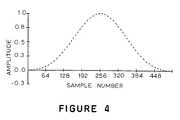
- FIG. 4depicts a window function which may be used to prevent transient effects that might otherwise occur at the boundaries between adjacent encoded blocks
- FIG. 5is a schematic block diagram of an arrangement for generating a seven-bit pseudo-noise synchronization sequence
- FIG. 6is a spectral plot of a “triple tone” audio block which forms the first block of a preferred synchronization sequence, where the thin line of the plot is the spectrum of the original audio signal and the thick line of the plot is the spectrum of the modulated signal;
- FIG. 7 aschematically depicts an arrangement of synchronization and information blocks usable to form a complete code message
- FIG. 7 bschematically depicts further details of the synchronization block shown in FIG. 7 a;
- FIG. 8is a flow chart depicting steps performed by a decoder of the system shown in FIG. 1;
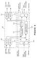
- FIG. 9illustrates an encoding arrangement in which audio encoding delays are compensated in the video data stream.
- Audio signalsare usually digitized at sampling rates that range between thirty-two kHz and forty-eight kHz. For example, a sampling rate of 44.1 kHz is commonly used during the digital recording of music. However, digital television (“DTV”) is likely to use a forty eight kHz sampling rate.
- DTVdigital television
- another parameter of interest in digitizing an audio signalis the number of binary bits used to represent the audio signal at each of the instants when it is sampled. This number of binary bits can vary, for example, between sixteen and twenty four bits per sample. The amplitude dynamic range resulting from using sixteen bits per sample of the audio signal is ninety-six dB.
- the dynamic range resulting from using twenty-four bits per sampleis 144 dB.
- Compression of audio signalsis performed in order to reduce this data rate to a level which makes it possible to transmit a stereo pair of such data on a channel with a throughput as low as 192 kbits/s.
- This compressiontypically is accomplished by transform coding.
- overlapped blocksare commonly used.
- a blockincludes 512 samples of “old” samples (i.e., samples from a previous block ) and 512 samples of “new” or current samples.
- the spectral representation of such a blockis divided into critical bands where each band comprises a group of several neighboring frequencies. The power in each of these bands can be calculated by summing the squares of the amplitudes of the frequency components within the band.
- Audio compressionis based on the principle of masking that, in the presence of high spectral energy at one frequency (i.e., the masking frequency), the human ear is unable to perceive a lower energy signal if the lower energy signal has a frequency (i.e., the masked frequency) near that of the higher energy signal.
- the lower energy signal at the masked frequencyis called a masked signal.
- a masking thresholdwhich represents either (i) the acoustic energy required at the masked frequency in order to make it audible or (ii) an energy change in the existing spectral value that would be perceptible, can be dynamically computed for each band.
- the frequency components in a masked bandcan be represented in a coarse fashion by using fewer bits based on this masking threshold. That is, the masking thresholds and the amplitudes of the frequency components in each band are coded with a smaller number of bits which constitute the compressed audio. Decompression reconstructs the original signal based on this data.
- FIG. 1illustrates an audience measurement system 10 in which an encoder 12 adds an ancillary code to an audio signal portion 14 of a broadcast signal.
- the encoder 12may be provided, as is known in the art, at some other location in the broadcast signal distribution chain.
- a transmitter 16transmits the encoded audio signal portion with a video signal portion 18 of the broadcast signal.
- the ancillary codeis recovered by processing the audio signal portion of the received broadcast signal even though the presence of that ancillary code is imperceptible to a listener when the encoded audio signal portion is supplied to speakers 24 of the receiver 20 .
- a decoder 26is connected either directly to an audio output 28 available at the receiver 20 or to a microphone 30 placed in the vicinity of the speakers 24 through which the audio is reproduced.
- the received audio signalcan be either in a monaural or stereo format.
- the encoder 12should preferably use frequencies and critical bands that match those used in compression.
- a suitable value for N Cmay be, for example, 512.
- a step 40 of the flow chart shown in FIG. 2which is executed by the encoder 12 , a first block v(t) of jN C samples is derived from the audio signal portion 14 by the encoder 12 such as by use of an analog to digital converter, where v(t) is the time-domain representation of the audio signal within the block.
- An optional windowmay be applied to v(t) at a block 42 as discussed below in additional detail. Assuming for the moment that no such window is used, a Fourier Transform I ⁇ v(t) ⁇ of the block v(t) to be coded is computed at a step 44 . (The Fourier Transform implemented at the step 44 may be a Fast Fourier Transform.)
- equation (1)is used in the following discussion to relate a frequency f j and its corresponding index I j .
- the code frequencies f i used for coding a blockmay be chosen from the Fourier Transform I ⁇ v(t) ⁇ at a step 46 in the 4.8 kHz to 6 kHz range in order to exploit the higher auditory threshold in this band. Also, each successive bit of the code may use a different pair of code frequencies f 1 and f 0 denoted by corresponding code frequency indexes I 1 and I 0 . There are two preferred ways of selecting the code frequencies f 1 and f 0 at the step 46 so as to create an inaudible wide-band noise like code.
- One way of selecting the code frequencies f 1 and f 0 at the step 46is to compute the code frequencies by use of a frequency hopping algorithm employing a hop sequence H s and a shift index I shift .
- H sis an ordered sequence of N s numbers representing the frequency deviation relative to a predetermined reference index I 5k .
- the indices for the N s bits resulting from a hop sequencemay be given by the following equations:
- the mid-frequency indexis given by the following equation:
- I midrepresents an index mid-way between the code frequency indices I 1 and I 0 . Accordingly, each of the code frequency indices is offset from the mid-frequency index by the same magnitude, I shift , but the two offsets have opposite signs.
- Another way of selecting the code frequencies at the step 46is to determine a frequency index I max at which the spectral power of the audio signal, as determined as the step 44 , is a maximum in the low frequency band extending from zero Hz to two kHz.
- I maxis the index corresponding to the frequency having maximum power in the range of 0-2 kHz. It is useful to perform this calculation starting at index 1, because index 0 represents the “local” DC component and may be modified by high pass filters used in compression.
- the code frequency indices I 1 and I 0are chosen relative to the frequency index I max so that they lie in a higher frequency band at which the human ear is relatively less sensitive.
- I shiftis a shift index
- I maxvaries according to the spectral power of the audio signal.
- the present inventiondoes not rely on a single fixed frequency. Accordingly, a “frequency-hopping” effect is created similar to that seen in spread spectrum modulation systems. However, unlike spread spectrum, the object of varying the coding frequencies of the present invention is to avoid the use of a constant code frequency which may render it audible.
- FSKFrequency Shift Keying
- PSKPhase Shift Keying
- the spectral power at I 1is increased to a level such that it constitutes a maximum in its corresponding neighborhood of frequencies.
- the neighborhood of indices corresponding to this neighborhood of frequenciesis analyzed at a step 48 in order to determine how much the code frequencies f 1 and f 0 must be boosted and attenuated so that they are detectable by the decoder 26 .
- the neighborhoodmay preferably extend from I 1 ⁇ 2 to I 1 +2, and is constrained to cover a narrow enough range of frequencies that the neighborhood of I 1 does not overlap the neighborhood of I 0 .
- the spectral power at I 0is modified in order to make it a minimum in its neighborhood of indices ranging from I 0 ⁇ 2 to I 0 +2.
- the power at I 0is boosted and the power at I 1 is attenuated in their corresponding neighborhoods.
- FIG. 3shows a typical spectrum 50 of an jN C sample audio block plotted over-a range of frequency index from forty five to seventy seven.
- a spectrum 52shows the audio block after coding of a ‘1’ bit
- a spectrum 54shows the audio block before coding.
- the hop sequence valueis five which yields a mid-frequency index of fifty eight.
- the values for I 1 and I 0are fifty three and sixty three, respectively.
- the spectral amplitude at fifty threeis then modified at a step 56 of FIG. 2 in order to make it a maximum within its neighborhood of indices.
- the amplitude at sixty threealready constitutes a minimum and, therefore, only a small additional attenuation is applied at the step 56 .
- the spectral power modification processrequires the computation of four values each in the neighborhood of I 1 and I 0 .
- these four valuesare as follows: (1) I max1 which is the index of the frequency in the neighborhood of I 1 having maximum power; (2) P max1 which is the spectral power at I max1 ; (3) I min1 which is the index of the frequency in the neighborhood of I 1 having minimum power; and (4) P min1 which is the spectral power at I min1 .
- Corresponding values for the I 0 neighborhoodare I max0 , P max0 , I min0 , and P min .
- AThe condition for imperceptibility requires a low value for A, whereas the condition for compression survivability requires a large value for A.
- a fixed value of Amay not lend itself to only a token increase or decrease of power. Therefore, a more logical choice for A would be a value based on the local masking threshold. In this case, A is variable, and coding can be achieved with a minimal incremental power level change and yet survive compression.
- the Fourier Transform of the block to be coded as determined at the step 44also contains negative frequency components with indices ranging in index values from ⁇ 256 to ⁇ 1.
- Spectral amplitudes at frequency indices ⁇ I 1 and ⁇ I 0must be set to values representing the complex conjugate of amplitudes at I 1 and I 0 , respectively, according to the following equations:
- f(I)is the complex spectral amplitude at index I.
- the modified frequency spectrum which now contains the binary codeis subjected to an inverse transform operation at a step 62 in order to obtain the encoded time domain signal, as will be discussed below.
- Compression algorithmsbased on the effect of masking modify the amplitude of individual spectral components by means of a bit allocation algorithm.
- Frequency bands subjected to a high level of masking by the presence of high spectral energies in neighboring bandsare assigned fewer bits, with the result that their amplitudes are coarsely quantized.
- the decompressed audiounder most conditions tends to maintain relative amplitude levels at frequencies within a neighborhood.
- the selected frequencies in the encoded audio stream which have been amplified or attenuated at the step 56will, therefore, maintain their relative positions even after a compression/decompression process.
- the Fourier Transform I ⁇ v(t) ⁇ of a blockmay not result in a frequency component of sufficient amplitude at the frequencies f 1 and f 0 to permit encoding of a bit by boosting the power at the appropriate frequency. In this event, it is preferable not to encode this block and to instead encode a subsequent block where the power of the signal at the frequencies f 1 and f 0 is appropriate for encoding.
- the spectral amplitudes at I 1 and I max1are swapped when encoding a one bit while retaining the original phase angles at I 1 and I max1 .
- a similar swap between the spectral amplitudes at I 0 and I max0is also performed.
- I 1 and I 0are reversed as in the case of amplitude modulation.
- swappingis also applied to the corresponding negative frequency indices.
- This encoding approachresults in a lower audibility level because the encoded signal undergoes only a minor frequency distortion. Both the unencoded and encoded signals have identical energy values.
- phase angle associated with I 1can be computed in a similar fashion.
- the phase angle of one of these componentsusually the component with the lower spectral amplitude, can be modified to be either in phase (i.e., 0°) or out of phase (i.e., 180°) with respect to the other component, which becomes the reference.
- a binary 0may be encoded as an in-phase modification and a binary 1 encoded as an out-of-phase modification.
- a binary 1may be encoded as an in-phase modification and a binary 0 encoded as an out-of-phase modification.
- the phase angle of the component that is modifiedis designated ⁇ M
- the phase angle of the other componentis designated ⁇ R .
- one of the spectral componentsmay have to undergo a maximum phase change of 180°, which could make the code audible.
- phase modulationit is not essential to perform phase modulation to this extent, as it is only necessary to ensure that the two components are either “close” to one another in phase or “far” apart. Therefore, at the step 48 , a phase neighborhood extending over a range of ⁇ /4 around ⁇ R , the reference component, and another neighborhood extending over a range of ⁇ /4 around ⁇ R + ⁇ may be chosen.
- the modifiable spectral componenthas its phase angle ⁇ M modified at the step 56 so as to fall into one of these phase neighborhoods depending upon whether a binary ‘0’ or a binary ‘1’ is being encoded.
- phase modificationmay be necessary. In typical audio streams, approximately 30% of the segments are “self-coded” in this manner and no modulation is required.
- the inverse Fourier Transformis determined at the step 62 .
- a single code frequency index, I 1selected as in the case of the other modulation schemes, is used.
- a neighborhood defined by indexes I 1 , I 1 +1, I 1 +2, and I 1 +3,is analyzed to determine whether the index Im corresponding to the spectral component having the maximum power in this neighborhood is odd or even. If the bit to be encoded is a ‘1’ and the index I m is odd, then the block being coded is assumed to be “auto-coded.” Otherwise, an odd-indexed frequency in the neighborhood is selected for amplification in order to make it a maximum. A bit ‘0’ is coded in a similar manner using an even index.
- a practical problem associated with block coding by either amplitude or phase modulation of the type described aboveis that large discontinuities in the audio signal can arise at a boundary between successive blocks. These sharp transitions can render the code audible.
- the time-domain signal v(t)can be multiplied by a smooth envelope or window function w(t) at the step 42 prior to performing the Fourier Transform at the step 44 .
- No window functionis required for the modulation by frequency swapping approach described herein.
- the frequency distortionis usually small enough to produce only minor edge discontinuities in the time domain between adjacent blocks.
- the window function w(t)is depicted in FIG. 4 . Therefore, the analysis performed at the step 54 is limited to the central section of the block resulting from I m ⁇ v(t)w(t) ⁇ . The required spectral modulation is implemented at the step 56 on the transform I ⁇ v(t)w(t) ⁇ .
- PN77-bit PN sequence
- the particular sequencedepends upon an initial setting of the shift register 58 .
- each individual bit of datais represented by this PN sequence—i.e., 1110100 is used for a bit ‘1, ’ and the complement 0001011 is used for a bit ‘0.’
- the use of seven bits to code each bit of coderesults in extremely high coding overheads.
- An alternative methoduses a plurality of PN15 sequences, each of which includes five bits of code data and 10 appended error correction bits. This representation provides a Hamming distance of 7 between any two 5-bit code data words. Up to three errors in a fifteen bit sequence can be detected and corrected. This PN15 sequence is ideally suited for a channel with a raw bit error rate of 20%.
- a unique synchronization sequence 66(FIG. 7 a ) is required for synchronization in order to distinguish PN15 code bit sequences 74 from other bit sequences in the coded data stream.
- the first code block of the synchronization sequence 66uses a “triple tone” 70 of the synchronization sequence in which three frequencies with indices I 0 , I 1 , and I mid are all amplified sufficiently that each becomes a maximum in its respective neighborhood, as depicted by way of example in FIG. 6 .
- the triple tone 70by amplifying the signals at the three selected frequencies to be relative maxima in their respective frequency neighborhoods, those signals could instead be locally attenuated so that the three associated local extreme values comprise three local minima. It should be noted that any combination of local maxima and local minima could be used for the triple tone 70 . However, because broadcast audio signals include substantial periods of silence, the preferred approach involves local amplification rather than local attenuation. Being the first bit in a sequence, the hop sequence value for the block from which the triple tone 70 is derived is two and the mid-frequency index is fifty-five. In order to make the triple tone block truly unique, a shift index of seven may be chosen instead of the usual five.
- the triple tone 70is the first block of the fifteen block sequence 66 and essentially represents one bit of synchronization data.
- the remaining fourteen blocks of the synchronization sequence 66are made up of two PN7 sequences: 1110100, 0001011. This makes the fifteen synchronization blocks distinct from all the PN sequences representing code data.
- the code data to be transmittedis converted into five bit groups, each of which is represented by a PN15 sequence.
- an unencoded block 72is inserted between each successive pair of PN sequences 74 .
- this unencoded block 72 (or gap) between neighboring PN sequences 74allows precise synchronizing by permitting a search for a correlation maximum across a range of audio samples.
- the left and right channelsare encoded with identical digital data.
- the left and right channelsare combined to produce a single audio signal stream. Because the frequencies selected for modulation are identical in both channels, the resulting monophonic sound is also expected to have the desired spectral characteristics so that, when decoded, the same digital code is recovered.
- the embedded digital codecan be recovered from the audio signal available at the audio output 28 of the receiver 20 .
- an analog signalcan be reproduced by means of the microphone 30 placed in the vicinity of the speakers 24 .
- the decoder 20converts the analog audio to a sampled digital output stream at a preferred sampling rate matching the sampling rate of the encoder 12 .
- a half-rate samplingcould be used.
- the digital outputsare processed directly by the decoder 26 without sampling but at a data rate suitable for the decoder 26 .
- the task of decodingis primarily one of matching the decoded data bits with those of a PN15 sequence which could be either a synchronization sequence or a code data sequence representing one or more code data bits.
- a PN15 sequencewhich could be either a synchronization sequence or a code data sequence representing one or more code data bits.
- amplitude modulated audio blocksis considered here.
- decoding of phase modulated blocksis virtually identical, except for the spectral analysis, which would compare phase angles rather than amplitude distributions, and decoding of index modulated blocks would similarly analyze the parity of the frequency index with maximum power in the specified neighborhood. Audio blocks encoded by frequency swapping can also be decoded by the same process.
- the ability to decode an audio stream in real-timeis highly desirable. It is also highly desirable to transmit the decoded data to a central office.
- the decoder 26may be arranged to run the decoding algorithm described below on Digital Signal Processing (DSP) based hardware typically used in such applications.
- DSPDigital Signal Processing
- the incoming encoded audio signalmay be made available to the decoder 26 from either the audio output 28 or from the microphone 30 placed in the vicinity of the speakers 24 .
- the decoder 26may sample the incoming encoded audio signal at half (24 kHz) of the normal 48 kHz sampling rate.
- the decoder 26may be arranged to achieve real-time decoding by implementing an incremental or sliding Fast Fourier Transform routine 100 (FIG. 8) coupled with the use of a status information array SIS that is continuously updated as processing progresses.
- the decoder 26computes the spectral amplitude only at frequency indexes that belong to the neighborhoods of interest, i.e., the neighborhoods used by the encoder 12 .
- frequency indexesranging from 45 to 70 are adequate so that the corresponding frequency spectrum contains only twenty-six frequency bins. Any code that is recovered appears in one or more elements of the status information array SIS as soon as the end of a message block is encountered.
- 256 sample blocksmay be processed such that, in each block of 256 samples to be processed, the last k samples are “new” and the remaining 256 ⁇ k samples are from a previous analysis.
- Each element SIS[p] of the status information array SISconsists of five members: a previous condition status PCS, a next jump index JI, a group counter GC, a raw data array DA, and an output data array OP.
- the raw data array DAhas the capacity to hold fifteen integers.
- the output data array OPstores ten integers, with each integer of the output data array OP corresponding to a five bit number extracted from a recovered PN15 sequence. This PN15 sequence, accordingly, has five actual data bits and ten other bits. These other bits-may be used, for example, for error correction. It is assumed here that the useful data in a message block consists of 50 bits divided into 10 groups with each group containing 5 bits, although a message block of any size may be used.
- the operation of the status information array SISis best explained in connection with FIG. 8 .
- An initial block of 256 samples of received audiois read into a buffer at a processing stage 102 .
- the initial block of 256 samplesis analyzed at a processing stage 104 by a conventional Fast Fourier Transform to obtain its spectral power distribution. All subsequent transforms implemented by the routine 100 use the high-speed incremental approach referred to above and described below.
- the Fast Fourier Transform corresponding to the initial 256 sample block read at the processing stage 102is tested at a processing stage 106 for a triple tone, which represents the first bit in the synchronization sequence.
- the presence of a triple tonemay be determined by examining the initial 256 sample block for the indices I 0 , I 1 , and I mid used by the encoder 12 in generating the triple tone, as described above.
- the SIS[p] element of the SIS array that is associated with this initial block of 256 samplesis SIS[0], where the status array index p is equal to 0.
- the values of certain members of the SIS[0] element of the status information array SISare changed at a processing stage 108 as follows: the previous condition status PCS, which is initially set to 0, is changed to a 1 indicating that a triple tone was found in the sample block corresponding to SIS[0]; the value of the next jump index JI is incremented to 1; and, the first integer of the raw data member DA[0] in the raw data array DA is set to the value (0 or 1) of the triple tone. In this case, the first integer of the raw data member DA[0] in the raw data array DA is set to 1 because it is assumed in this analysis that the triple tone is the equivalent of a 1 bit.
- the status array index pis incremented by one for the next sample block. If there is no triple tone, none of these changes in the SIS[0] element are made at the processing stage 108 , but the status array index p is still incremented by one for the next sample block. Whether or not a triple tone is detected in this 256 sample block, the routine 100 enters an incremental FFT mode at a processing stage 110 .
- a new 256 sample block incrementis read into the buffer at a processing stage 112 by adding four new samples to, and discarding the four oldest samples from, the initial 256 sample block processed at the processing stages 102 - 106 .
- This new 256 sample block incrementis analyzed at a processing stage 114 according to the following steps:
- STEP 1the skip factor k of the Fourier Transform is applied according to the following equation in order to modify each frequency component F old (u 0 ) of the spectrum corresponding to the initial sample block in order to derive a corresponding intermediate frequency component F 1 (u 0 ):
- F 1 ⁇ ( u 0 )F old ⁇ ( u 0 ) ⁇ exp - ( 2 ⁇ ⁇ ⁇ ⁇ u 0 ⁇ k 256 ) ( 15 )
- u 0is the frequency index of interest.
- the frequency index u 0varies from 45 to 70. It should be noted that this first step involves multiplication of two complex numbers.
- this second stepinvolves the addition of a complex number to the summation of a product of a real number and a complex number. This computation is repeated across the frequency index range of interest (for example, 45 to 70).
- STEP 3the effect of the multiplication of the 256 sample block by the window function in the encoder 12 is then taken into account. That is, the results of step 2 above are not confined by the window function that is used in the encoder 12 . Therefore, the results of step 2 preferably should be multiplied by this window function. Because multiplication in the time domain is equivalent to a convolution of the spectrum by the Fourier Transform of the window function, the results from the second step may be convolved with the window function.
- T Wis the width of the window in the time domain.
- This “raised cosine” functionrequires only three multiplication and addition operations involving the real and imaginary parts of the spectral amplitude. This operation significantly improves computational speed. This step is not required for the case of modulation by frequency swapping.
- STEP 4the spectrum resulting from step 3 is then examined for the presence of a triple tone. If a triple tone is found, the values of certain members of the SIS[1] element of the status information array SIS are set at a processing stage 116 as follows: the previous condition status PCS, which is initially set to 0, is changed to a 1; the value of the next jump index JI is incremented to 1; and, the first integer of the raw data member DA[1] in the raw data array DA is set to 1. Also, the status array index p is incremented by one. If there is no triple tone, none of these changes are made to the members of the structure of the SIS[1] element at the processing stage 116 , but the status array index p is still incremented by one.
- this analysis corresponding to the processing stages 112 - 120proceeds in the manner described above in four sample increments where p is incremented for each sample increment.
- pis reset to 0 at the processing stage 118 and the 256 sample block increment now in the buffer is exactly 256 samples away from the location in the audio stream at which the SIS[0] element was last updated.
- Each of the new block increments beginning where p was reset to 0is analyzed for the next bit in the synchronization sequence.
- This analysisuses the second member of the hop sequence H, because the next jump index JI is equal to 1.
- the I 1 and I 0 indexescan be determined, for example from equations (2) and (3).
- the neighborhoods of the I 1 and I 0 indexesare analyzed to locate maximums and minimums in the case of amplitude modulation. If, for example, a power maximum at I 1 and a power minimum at I 0 are detected, the next bit in the synchronization sequence is taken to be 1.
- the index for either the maximum power or minimum power in a neighborhoodis allowed to deviate by 1 from its expected value. For example, if a power maximum is found in the index I 1 , and if the power minimum in the index I 0 neighborhood is found at I 0 ⁇ 1, instead of I 0 , the next bit in the synchronization sequence is still taken to be 1. On the other hand, if a power minimum at I 1 and a power maximum at I 0 are detected using the same allowable variations discussed above, the next bit in the synchronization sequence is taken to be 0. However, if none of these conditions are satisfied, the output code is set to ⁇ 1, indicating a sample block that cannot be decoded.
- the second integer of the raw data member DA[1] in the raw data array DAis set to the appropriate value, and the next jump index JI of SIS[0] is incremented to 2, which corresponds to the third member of the hop sequence H s .
- the I 1 and I 0 indexescan be determined.
- the neighborhoods of the I 1 and I 0 indexesare analyzed to locate maximums and minimums in the case of amplitude modulation so that the value of the next bit can be decoded from the third set of 64 block increments, and so on for fifteen such bits of the synchronization sequence.
- the fifteen bits stored in the raw data array DAmay then be compared with a reference synchronization sequence to determine synchronization. If the number of errors between the fifteen bits stored in the raw data array DA and the reference synchronization sequence exceeds a previously set threshold, the extracted sequence is not acceptable as a synchronization, and the search for the synchronization sequence begins anew with a search for a triple tone.
- the PN15 data sequencesmay then be extracted using the same analysis as is used for the synchronization sequence, except that detection of each PN15 data sequence is not conditioned upon detection of the triple tone which is reserved for the synchronization sequence. As each bit of a PN15 data sequence is found, it is inserted as a corresponding integer of the raw data array DA.
- the output data array OPwhich contains a full 50-bit message, is read at a processing stage 122 .
- the total number of samples in a message blockis 45,056 at a half-rate sampling frequency of 24 kHz. It is possible that several adjacent elements of the status information array SIS, each representing a message block separated by four samples from its neighbor, may lead to the recovery of the same message because synchronization may occur at several locations in the audio stream which are close to one another. If all these messages are identical, there is a high probability that an error-free code has been received.
- the previous condition status PCS of the corresponding SIS elementis set to 0 at a processing stage 124 so that searching is resumed at a processing stage 126 for the triple tone of the synchronization sequence of the next message block.
- the network originator of the programmay insert its identification code and time stamp, and a network affiliated station carrying this program may also insert its own identification code.
- an advertiser or sponsormay wish to have its code added.
- 48 bits in a 50-bit systemcan be used for the code and the remaining 2 bits can be used for level specification.
- the first program material generatorsay the network, will insert codes in the audio stream. Its first message block would have the level bits set to 00, and only a synchronization sequence and the 2 level bits are set for the second and third message blocks in the case of a three level system.
- the level bits for the second and third messagesmay be both set to 11 indicating that the actual data areas have been left unused.
- the network affiliated stationcan now enter its code with a decoder/encoder combination that would locate the synchronization of the second message block with the 11 level setting.
- This stationinserts its code in the data area of this block and sets the level bits to 01.
- the next level encoderinserts its code in the third message block's data area and sets the level bits to 10.
- the level bitsdistinguish each message level category.
- Erasuremay be accomplished by detecting the triple tone/synchronization sequence using a decoder and by then modifying at least one of the triple tone frequencies such that the code is no longer recoverable.
- Overwritinginvolves extracting the synchronization sequence in the audio, testing the data bits in the data area and inserting a new bit only in those blocks that do not have the desired bit value. The new bit is inserted by amplifying and attenuating appropriate frequencies in the data area.
- N C samples of audioare processed at any given time.
- the following four buffersare used: input buffers IN 0 and IN 1 , and output buffers OUT 0 and OUT 1 .
- Each of these bufferscan hold N C samples. While samples in the input buffer IN 0 are being processed, the input buffer IN 1 receives new incoming samples. The processed output samples from the input buffer IN 0 are written into the output buffer OUT 0 , and samples previously encoded are written to the output from the output buffer OUT 1 .
- FIG. 9Such a compensation arrangement is shown in FIG. 9 .
- an encoding arrangement 200which may be used for the elements 12 , 14 , and 18 in FIG. 1, is arranged to receive either analog video and audio inputs or digital video and audio inputs.
- Analog video and audio inputsare supplied to corresponding video and audio analog to digital converters 202 and 204 .
- the audio samples from the audio analog to digital converter 204are provided to an audio encoder 206 which may be of known design or which may be arranged as disclosed above.
- the digital audio inputis supplied directly to the audio encoder 206 .
- the input digital bitstreamis a combination of digital video and audio bitstream portions
- the input digital bitstreamis provided to a demultiplexer 208 which separates the digital video and audio portions of the input digital bitstream and supplies the separated digital audio portion to the audio encoder 206 .
- a delay 210is introduced in the digital video bitstream.
- the delay imposed on the digital video bitstream by the delay 210is equal to the delay imposed on the digital audio bitstream by the audio encoder 206 . Accordingly, the digital video and audio bitstreams downstream of the encoding arrangement 200 will be synchronized.
- the output of the delay 210is provided to a video digital to analog converter 212 and the output of the audio encoder 206 is provided to an audio digital to analog converter 214 .
- the output of the delay 210is provided directly as a digital video output of the encoding arrangement 200 and the output of the audio encoder 206 is provided directly as a digital audio output of the encoding arrangement 200 .
- the outputs of the delay 210 and of the audio encoder 206are provided to a multiplexer 216 which recombines the digital video and audio bitstreams as an output of the encoding arrangement 200 .
- the encoding arrangement 200includes a delay 210 which imposes a delay on the video bitstream in order to compensate for the delay imposed on the audio bitstream by the audio encoder 206 .
- some embodiments of the encoding arrangement 200may include a video encoder 218 , which may be of known design, in order to encode the video output of the video analog to digital converter 202 , or the input digital video bitstream, or the output of the demultiplexer 208 , as the case may be.
- the audio encoder 206 and/or the video encoder 218may be adjusted so that the relative delay imposed on the audio and video bitstreams is zero and so that the audio and video bitstreams are thereby synchronized.
- the delay 210is not necessary.
- the delay 210may be used to provide a suitable delay and may be inserted in either the video or audio processing so that the relative delay imposed on the audio and video bitstreams is zero and so that the audio and video bitstreams are thereby synchronized.
- the video encoder 218 and not the audio encoder 206may be used.
- the delay 210may be required in order to impose a delay on the audio bitstream so that the relative delay between the audio and video bitstreams is zero and so that the audio and video bitstreams are thereby synchronized.
Landscapes
- Engineering & Computer Science (AREA)
- Signal Processing (AREA)
- Compression, Expansion, Code Conversion, And Decoders (AREA)
- Reduction Or Emphasis Of Bandwidth Of Signals (AREA)
- Television Systems (AREA)
- Signal Processing For Digital Recording And Reproducing (AREA)
- Digital Transmission Methods That Use Modulated Carrier Waves (AREA)
Abstract
Description


Claims (6)

Priority Applications (1)
| Application Number | Priority Date | Filing Date | Title |
|---|---|---|---|
| US10/444,409US6807230B2 (en) | 1998-07-16 | 2003-05-23 | Broadcast encoding system and method |
Applications Claiming Priority (3)
| Application Number | Priority Date | Filing Date | Title |
|---|---|---|---|
| US09/116,397US6272176B1 (en) | 1998-07-16 | 1998-07-16 | Broadcast encoding system and method |
| US09/882,089US6621881B2 (en) | 1998-07-16 | 2001-06-15 | Broadcast encoding system and method |
| US10/444,409US6807230B2 (en) | 1998-07-16 | 2003-05-23 | Broadcast encoding system and method |
Related Parent Applications (1)
| Application Number | Title | Priority Date | Filing Date |
|---|---|---|---|
| US09/882,089DivisionUS6621881B2 (en) | 1998-07-16 | 2001-06-15 | Broadcast encoding system and method |
Publications (2)
| Publication Number | Publication Date |
|---|---|
| US20030194004A1 US20030194004A1 (en) | 2003-10-16 |
| US6807230B2true US6807230B2 (en) | 2004-10-19 |
Family
ID=22366946
Family Applications (4)
| Application Number | Title | Priority Date | Filing Date |
|---|---|---|---|
| US09/116,397Expired - LifetimeUS6272176B1 (en) | 1998-07-16 | 1998-07-16 | Broadcast encoding system and method |
| US09/882,089Expired - LifetimeUS6621881B2 (en) | 1998-07-16 | 2001-06-15 | Broadcast encoding system and method |
| US09/882,085Expired - LifetimeUS6504870B2 (en) | 1998-07-16 | 2001-06-15 | Broadcast encoding system and method |
| US10/444,409Expired - LifetimeUS6807230B2 (en) | 1998-07-16 | 2003-05-23 | Broadcast encoding system and method |
Family Applications Before (3)
| Application Number | Title | Priority Date | Filing Date |
|---|---|---|---|
| US09/116,397Expired - LifetimeUS6272176B1 (en) | 1998-07-16 | 1998-07-16 | Broadcast encoding system and method |
| US09/882,089Expired - LifetimeUS6621881B2 (en) | 1998-07-16 | 2001-06-15 | Broadcast encoding system and method |
| US09/882,085Expired - LifetimeUS6504870B2 (en) | 1998-07-16 | 2001-06-15 | Broadcast encoding system and method |
Country Status (10)
| Country | Link |
|---|---|
| US (4) | US6272176B1 (en) |
| EP (3) | EP1843496A3 (en) |
| JP (1) | JP4030036B2 (en) |
| CN (1) | CN1148901C (en) |
| AR (2) | AR013810A1 (en) |
| AU (4) | AU771289B2 (en) |
| CA (3) | CA2332977C (en) |
| DE (1) | DE69838401T2 (en) |
| ES (1) | ES2293693T3 (en) |
| WO (1) | WO2000004662A1 (en) |
Cited By (6)
| Publication number | Priority date | Publication date | Assignee | Title |
|---|---|---|---|---|
| US20030093783A1 (en)* | 2001-11-09 | 2003-05-15 | Daniel Nelson | Apparatus and method for detecting and correcting a corrupted broadcast time code |
| US20050232411A1 (en)* | 1999-10-27 | 2005-10-20 | Venugopal Srinivasan | Audio signature extraction and correlation |
| WO2008008911A2 (en) | 2006-07-12 | 2008-01-17 | Arbitron Inc. | Methods and systems for compliance confirmation and incentives |
| US10895848B1 (en)* | 2020-03-17 | 2021-01-19 | Semiconductor Components Industries, Llc | Methods and apparatus for selective histogramming |
| US11676614B2 (en) | 2014-03-03 | 2023-06-13 | Samsung Electronics Co., Ltd. | Method and apparatus for high frequency decoding for bandwidth extension |
| US11688406B2 (en) | 2014-03-24 | 2023-06-27 | Samsung Electronics Co., Ltd. | High-band encoding method and device, and high-band decoding method and device |
Families Citing this family (260)
| Publication number | Priority date | Publication date | Assignee | Title |
|---|---|---|---|---|
| US6944298B1 (en) | 1993-11-18 | 2005-09-13 | Digimare Corporation | Steganographic encoding and decoding of auxiliary codes in media signals |
| US6614914B1 (en) | 1995-05-08 | 2003-09-02 | Digimarc Corporation | Watermark embedder and reader |
| US6449377B1 (en) | 1995-05-08 | 2002-09-10 | Digimarc Corporation | Methods and systems for watermark processing of line art images |
| US6611607B1 (en)* | 1993-11-18 | 2003-08-26 | Digimarc Corporation | Integrating digital watermarks in multimedia content |
| US5768426A (en)* | 1993-11-18 | 1998-06-16 | Digimarc Corporation | Graphics processing system employing embedded code signals |
| US6636615B1 (en) | 1998-01-20 | 2003-10-21 | Digimarc Corporation | Methods and systems using multiple watermarks |
| US8505108B2 (en) | 1993-11-18 | 2013-08-06 | Digimarc Corporation | Authentication using a digital watermark |
| US6983051B1 (en)* | 1993-11-18 | 2006-01-03 | Digimarc Corporation | Methods for audio watermarking and decoding |
| US7171016B1 (en) | 1993-11-18 | 2007-01-30 | Digimarc Corporation | Method for monitoring internet dissemination of image, video and/or audio files |
| US5748763A (en) | 1993-11-18 | 1998-05-05 | Digimarc Corporation | Image steganography system featuring perceptually adaptive and globally scalable signal embedding |
| US7039214B2 (en) | 1999-11-05 | 2006-05-02 | Digimarc Corporation | Embedding watermark components during separate printing stages |
| US6973197B2 (en)* | 1999-11-05 | 2005-12-06 | Digimarc Corporation | Watermarking with separate application of the grid and payload signals |
| US20020136429A1 (en)* | 1994-03-17 | 2002-09-26 | John Stach | Data hiding through arrangement of objects |
| US6882738B2 (en)* | 1994-03-17 | 2005-04-19 | Digimarc Corporation | Methods and tangible objects employing textured machine readable data |
| US7724919B2 (en) | 1994-10-21 | 2010-05-25 | Digimarc Corporation | Methods and systems for steganographic processing |
| US6560349B1 (en)* | 1994-10-21 | 2003-05-06 | Digimarc Corporation | Audio monitoring using steganographic information |
| US7224819B2 (en) | 1995-05-08 | 2007-05-29 | Digimarc Corporation | Integrating digital watermarks in multimedia content |
| US6763123B2 (en) | 1995-05-08 | 2004-07-13 | Digimarc Corporation | Detection of out-of-phase low visibility watermarks |
| US6721440B2 (en) | 1995-05-08 | 2004-04-13 | Digimarc Corporation | Low visibility watermarks using an out-of-phase color |
| US6728390B2 (en)* | 1995-05-08 | 2004-04-27 | Digimarc Corporation | Methods and systems using multiple watermarks |
| US6718046B2 (en) | 1995-05-08 | 2004-04-06 | Digimarc Corporation | Low visibility watermark using time decay fluorescence |
| US6760463B2 (en) | 1995-05-08 | 2004-07-06 | Digimarc Corporation | Watermarking methods and media |
| US7054462B2 (en) | 1995-05-08 | 2006-05-30 | Digimarc Corporation | Inferring object status based on detected watermark data |
| US7006661B2 (en)* | 1995-07-27 | 2006-02-28 | Digimarc Corp | Digital watermarking systems and methods |
| US20030056103A1 (en) | 2000-12-18 | 2003-03-20 | Levy Kenneth L. | Audio/video commerce application architectural framework |
| US7412072B2 (en)* | 1996-05-16 | 2008-08-12 | Digimarc Corporation | Variable message coding protocols for encoding auxiliary data in media signals |
| US6381341B1 (en) | 1996-05-16 | 2002-04-30 | Digimarc Corporation | Watermark encoding method exploiting biases inherent in original signal |
| JP3255022B2 (en)* | 1996-07-01 | 2002-02-12 | 日本電気株式会社 | Adaptive transform coding and adaptive transform decoding |
| US6108637A (en) | 1996-09-03 | 2000-08-22 | Nielsen Media Research, Inc. | Content display monitor |
| US6675383B1 (en) | 1997-01-22 | 2004-01-06 | Nielsen Media Research, Inc. | Source detection apparatus and method for audience measurement |
| US6643696B2 (en) | 1997-03-21 | 2003-11-04 | Owen Davis | Method and apparatus for tracking client interaction with a network resource and creating client profiles and resource database |
| EP0901282B1 (en)* | 1997-09-03 | 2006-06-28 | Hitachi, Ltd. | Method for recording and reproducing electronic watermark information |
| US6804376B2 (en) | 1998-01-20 | 2004-10-12 | Digimarc Corporation | Equipment employing watermark-based authentication function |
| US7006555B1 (en)* | 1998-07-16 | 2006-02-28 | Nielsen Media Research, Inc. | Spectral audio encoding |
| US7373513B2 (en)* | 1998-09-25 | 2008-05-13 | Digimarc Corporation | Transmarking of multimedia signals |
| US7197156B1 (en)* | 1998-09-25 | 2007-03-27 | Digimarc Corporation | Method and apparatus for embedding auxiliary information within original data |
| US7532740B2 (en)* | 1998-09-25 | 2009-05-12 | Digimarc Corporation | Method and apparatus for embedding auxiliary information within original data |
| US6442283B1 (en)* | 1999-01-11 | 2002-08-27 | Digimarc Corporation | Multimedia data embedding |
| US6871180B1 (en) | 1999-05-25 | 2005-03-22 | Arbitron Inc. | Decoding of information in audio signals |
| KR20010016704A (en)* | 1999-08-02 | 2001-03-05 | 구자홍 | apparatus for selecting input signal in digital TV |
| AUPQ206399A0 (en) | 1999-08-06 | 1999-08-26 | Imr Worldwide Pty Ltd. | Network user measurement system and method |
| JP2003527779A (en)* | 1999-09-01 | 2003-09-16 | ディジマーク コーポレイション | Method of forming watermark on digital image by specifying intensity for each area |
| JP4639441B2 (en)* | 1999-09-01 | 2011-02-23 | ソニー株式会社 | Digital signal processing apparatus and processing method, and digital signal recording apparatus and recording method |
| AU2881300A (en)* | 1999-10-27 | 2001-05-08 | Nielsen Media Research, Inc. | System and method for encoding an audio signal for use in broadcast program identification systems, by adding inaudible codes to the audio signal |
| US6757866B1 (en)* | 1999-10-29 | 2004-06-29 | Verizon Laboratories Inc. | Hyper video: information retrieval using text from multimedia |
| US6996775B1 (en)* | 1999-10-29 | 2006-02-07 | Verizon Laboratories Inc. | Hypervideo: information retrieval using time-related multimedia: |
| US6569206B1 (en)* | 1999-10-29 | 2003-05-27 | Verizon Laboratories Inc. | Facilitation of hypervideo by automatic IR techniques in response to user requests |
| EP1252735B1 (en) | 2000-01-12 | 2011-08-24 | Jupiter Media Metrix, Inc. | System and method for estimating prevalence of digital content on the world-wide-web |
| JP4785168B2 (en) | 2000-01-13 | 2011-10-05 | ディジマーク コーポレイション | Metadata authentication and embedding metadata in watermarks in media signals |
| US7127744B2 (en) | 2000-03-10 | 2006-10-24 | Digimarc Corporation | Method and apparatus to protect media existing in an insecure format |
| US8091025B2 (en) | 2000-03-24 | 2012-01-03 | Digimarc Corporation | Systems and methods for processing content objects |
| US20070136592A1 (en)* | 2000-04-12 | 2007-06-14 | Smith Richard A | Wireless internet gateway |
| US6891811B1 (en)* | 2000-04-18 | 2005-05-10 | Telecommunication Systems Inc. | Short messaging service center mobile-originated to HTTP internet communications |
| US6804377B2 (en) | 2000-04-19 | 2004-10-12 | Digimarc Corporation | Detecting information hidden out-of-phase in color channels |
| US8027509B2 (en) | 2000-04-19 | 2011-09-27 | Digimarc Corporation | Digital watermarking in data representing color channels |
| US7738673B2 (en) | 2000-04-19 | 2010-06-15 | Digimarc Corporation | Low visible digital watermarks |
| US6912295B2 (en) | 2000-04-19 | 2005-06-28 | Digimarc Corporation | Enhancing embedding of out-of-phase signals |
| US7027614B2 (en) | 2000-04-19 | 2006-04-11 | Digimarc Corporation | Hiding information to reduce or offset perceptible artifacts |
| US6891959B2 (en)* | 2000-04-19 | 2005-05-10 | Digimarc Corporation | Hiding information out-of-phase in color channels |
| US7305104B2 (en) | 2000-04-21 | 2007-12-04 | Digimarc Corporation | Authentication of identification documents using digital watermarks |
| US6879652B1 (en)* | 2000-07-14 | 2005-04-12 | Nielsen Media Research, Inc. | Method for encoding an input signal |
| EP1305901B1 (en) | 2000-07-27 | 2005-04-13 | Activated Content Corporation, Inc. | Stegotext encoder and decoder |
| FR2812503B1 (en)* | 2000-07-31 | 2003-03-28 | Telediffusion De France Tdf | CODING AND DECODING METHOD AND SYSTEM FOR DIGITAL INFORMATION IN A SOUND SIGNAL TRANSMITTED BY A REVERBERANT CHANNEL |
| US7346776B2 (en)* | 2000-09-11 | 2008-03-18 | Digimarc Corporation | Authenticating media signals by adjusting frequency characteristics to reference values |
| US6674876B1 (en) | 2000-09-14 | 2004-01-06 | Digimarc Corporation | Watermarking in the time-frequency domain |
| US6996521B2 (en) | 2000-10-04 | 2006-02-07 | The University Of Miami | Auxiliary channel masking in an audio signal |
| US6483927B2 (en)* | 2000-12-18 | 2002-11-19 | Digimarc Corporation | Synchronizing readers of hidden auxiliary data in quantization-based data hiding schemes |
| US8964604B2 (en) | 2000-12-26 | 2015-02-24 | Polycom, Inc. | Conference endpoint instructing conference bridge to dial phone number |
| US7221663B2 (en)* | 2001-12-31 | 2007-05-22 | Polycom, Inc. | Method and apparatus for wideband conferencing |
| US9001702B2 (en) | 2000-12-26 | 2015-04-07 | Polycom, Inc. | Speakerphone using a secure audio connection to initiate a second secure connection |
| US8948059B2 (en)* | 2000-12-26 | 2015-02-03 | Polycom, Inc. | Conference endpoint controlling audio volume of a remote device |
| US8126968B2 (en)* | 2000-12-26 | 2012-02-28 | Polycom, Inc. | System and method for coordinating a conference using a dedicated server |
| US7339605B2 (en)* | 2004-04-16 | 2008-03-04 | Polycom, Inc. | Conference link between a speakerphone and a video conference unit |
| US8977683B2 (en)* | 2000-12-26 | 2015-03-10 | Polycom, Inc. | Speakerphone transmitting password information to a remote device |
| US7864938B2 (en)* | 2000-12-26 | 2011-01-04 | Polycom, Inc. | Speakerphone transmitting URL information to a remote device |
| US7640031B2 (en)* | 2006-06-22 | 2009-12-29 | Telecommunication Systems, Inc. | Mobile originated interactive menus via short messaging services |
| US20030187798A1 (en)* | 2001-04-16 | 2003-10-02 | Mckinley Tyler J. | Digital watermarking methods, programs and apparatus |
| US7822969B2 (en)* | 2001-04-16 | 2010-10-26 | Digimarc Corporation | Watermark systems and methods |
| JP3576993B2 (en)* | 2001-04-24 | 2004-10-13 | 株式会社東芝 | Digital watermark embedding method and apparatus |
| US7046819B2 (en) | 2001-04-25 | 2006-05-16 | Digimarc Corporation | Encoded reference signal for digital watermarks |
| EP1388080A4 (en)* | 2001-05-10 | 2006-10-25 | Polycom Israel Ltd | CONTROL UNIT FOR A MULTI-PEDAL MULTIMEDIA / AUDIO SYSTEM |
| US8934382B2 (en) | 2001-05-10 | 2015-01-13 | Polycom, Inc. | Conference endpoint controlling functions of a remote device |
| US8976712B2 (en) | 2001-05-10 | 2015-03-10 | Polycom, Inc. | Speakerphone and conference bridge which request and perform polling operations |
| US6963543B2 (en)* | 2001-06-29 | 2005-11-08 | Qualcomm Incorporated | Method and system for group call service |
| US8572640B2 (en)* | 2001-06-29 | 2013-10-29 | Arbitron Inc. | Media data use measurement with remote decoding/pattern matching |
| US8094869B2 (en) | 2001-07-02 | 2012-01-10 | Digimarc Corporation | Fragile and emerging digital watermarks |
| US7100181B2 (en) | 2001-08-22 | 2006-08-29 | Nielsen Media Research, Inc. | Television proximity sensor |
| US7537170B2 (en)* | 2001-08-31 | 2009-05-26 | Digimarc Corporation | Machine-readable security features for printed objects |
| US7213757B2 (en)* | 2001-08-31 | 2007-05-08 | Digimarc Corporation | Emerging security features for identification documents |
| US6862355B2 (en) | 2001-09-07 | 2005-03-01 | Arbitron Inc. | Message reconstruction from partial detection |
| CA2470094C (en) | 2001-12-18 | 2007-12-04 | Digimarc Id Systems, Llc | Multiple image security features for identification documents and methods of making same |
| US7728048B2 (en) | 2002-12-20 | 2010-06-01 | L-1 Secure Credentialing, Inc. | Increasing thermal conductivity of host polymer used with laser engraving methods and compositions |
| US8885523B2 (en)* | 2001-12-31 | 2014-11-11 | Polycom, Inc. | Speakerphone transmitting control information embedded in audio information through a conference bridge |
| US8223942B2 (en)* | 2001-12-31 | 2012-07-17 | Polycom, Inc. | Conference endpoint requesting and receiving billing information from a conference bridge |
| US8023458B2 (en) | 2001-12-31 | 2011-09-20 | Polycom, Inc. | Method and apparatus for wideband conferencing |
| US8144854B2 (en)* | 2001-12-31 | 2012-03-27 | Polycom Inc. | Conference bridge which detects control information embedded in audio information to prioritize operations |
| US7742588B2 (en)* | 2001-12-31 | 2010-06-22 | Polycom, Inc. | Speakerphone establishing and using a second connection of graphics information |
| US8102984B2 (en)* | 2001-12-31 | 2012-01-24 | Polycom Inc. | Speakerphone and conference bridge which receive and provide participant monitoring information |
| US7787605B2 (en)* | 2001-12-31 | 2010-08-31 | Polycom, Inc. | Conference bridge which decodes and responds to control information embedded in audio information |
| US8934381B2 (en)* | 2001-12-31 | 2015-01-13 | Polycom, Inc. | Conference endpoint instructing a remote device to establish a new connection |
| US20050213726A1 (en)* | 2001-12-31 | 2005-09-29 | Polycom, Inc. | Conference bridge which transfers control information embedded in audio information between endpoints |
| US8705719B2 (en) | 2001-12-31 | 2014-04-22 | Polycom, Inc. | Speakerphone and conference bridge which receive and provide participant monitoring information |
| US8947487B2 (en)* | 2001-12-31 | 2015-02-03 | Polycom, Inc. | Method and apparatus for combining speakerphone and video conference unit operations |
| US7978838B2 (en) | 2001-12-31 | 2011-07-12 | Polycom, Inc. | Conference endpoint instructing conference bridge to mute participants |
| US20030131350A1 (en) | 2002-01-08 | 2003-07-10 | Peiffer John C. | Method and apparatus for identifying a digital audio signal |
| US7321667B2 (en)* | 2002-01-18 | 2008-01-22 | Digimarc Corporation | Data hiding through arrangement of objects |
| US7231061B2 (en)* | 2002-01-22 | 2007-06-12 | Digimarc Corporation | Adaptive prediction filtering for digital watermarking |
| US7966497B2 (en)* | 2002-02-15 | 2011-06-21 | Qualcomm Incorporated | System and method for acoustic two factor authentication |
| US20030212549A1 (en)* | 2002-05-10 | 2003-11-13 | Jack Steentra | Wireless communication using sound |
| US7824029B2 (en) | 2002-05-10 | 2010-11-02 | L-1 Secure Credentialing, Inc. | Identification card printer-assembler for over the counter card issuing |
| US7401224B2 (en)* | 2002-05-15 | 2008-07-15 | Qualcomm Incorporated | System and method for managing sonic token verifiers |
| JP3765413B2 (en)* | 2002-07-12 | 2006-04-12 | ソニー株式会社 | Information encoding apparatus and method, information decoding apparatus and method, recording medium, and program |
| US8271778B1 (en) | 2002-07-24 | 2012-09-18 | The Nielsen Company (Us), Llc | System and method for monitoring secure data on a network |
| US7239981B2 (en) | 2002-07-26 | 2007-07-03 | Arbitron Inc. | Systems and methods for gathering audience measurement data |
| US7395062B1 (en) | 2002-09-13 | 2008-07-01 | Nielson Media Research, Inc. A Delaware Corporation | Remote sensing system |
| US9711153B2 (en) | 2002-09-27 | 2017-07-18 | The Nielsen Company (Us), Llc | Activating functions in processing devices using encoded audio and detecting audio signatures |
| US7222071B2 (en) | 2002-09-27 | 2007-05-22 | Arbitron Inc. | Audio data receipt/exposure measurement with code monitoring and signature extraction |
| US8959016B2 (en) | 2002-09-27 | 2015-02-17 | The Nielsen Company (Us), Llc | Activating functions in processing devices using start codes embedded in audio |
| CA2502232C (en) | 2002-10-15 | 2013-10-01 | Trent J. Brundage | Identification document and related methods |
| CA2503340A1 (en) | 2002-10-23 | 2004-05-06 | Arun Ramaswamy | Digital data insertion apparatus and methods for use with compressed audio/video data |
| US6845360B2 (en) | 2002-11-22 | 2005-01-18 | Arbitron Inc. | Encoding multiple messages in audio data and detecting same |
| US7174151B2 (en) | 2002-12-23 | 2007-02-06 | Arbitron Inc. | Ensuring EAS performance in audio signal encoding |
| US7483835B2 (en) | 2002-12-23 | 2009-01-27 | Arbitron, Inc. | AD detection using ID code and extracted signature |
| AU2003234420A1 (en) | 2002-12-27 | 2004-07-29 | Nielsen Media Research, Inc. | Methods and apparatus for transcoding metadata |
| US6931076B2 (en)* | 2002-12-31 | 2005-08-16 | Intel Corporation | Signal detector |
| DE602004030434D1 (en) | 2003-04-16 | 2011-01-20 | L 1 Secure Credentialing Inc | THREE-DIMENSIONAL DATA STORAGE |
| US7460684B2 (en) | 2003-06-13 | 2008-12-02 | Nielsen Media Research, Inc. | Method and apparatus for embedding watermarks |
| US7289961B2 (en)* | 2003-06-19 | 2007-10-30 | University Of Rochester | Data hiding via phase manipulation of audio signals |
| US7043204B2 (en)* | 2003-06-26 | 2006-05-09 | The Regents Of The University Of California | Through-the-earth radio |
| AU2003279935A1 (en)* | 2003-08-29 | 2005-04-14 | Nielsen Media Research, Inc. | Methods and apparatus for embedding and recovering an image for use with video content |
| EP1668903A4 (en) | 2003-09-12 | 2011-01-05 | Nielsen Media Res Inc | Digital video signature apparatus and methods for use with video program identification systems |
| US7706565B2 (en) | 2003-09-30 | 2010-04-27 | Digimarc Corporation | Multi-channel digital watermarking |
| CA2542151C (en) | 2003-10-07 | 2013-03-26 | Nielsen Media Research, Inc. | Methods and apparatus to extract codes from a plurality of channels |
| WO2005041109A2 (en)* | 2003-10-17 | 2005-05-06 | Nielsen Media Research, Inc. | Methods and apparatus for identifiying audio/video content using temporal signal characteristics |
| US20060138631A1 (en)* | 2003-12-31 | 2006-06-29 | Advanced Semiconductor Engineering, Inc. | Multi-chip package structure |
| US8406341B2 (en) | 2004-01-23 | 2013-03-26 | The Nielsen Company (Us), Llc | Variable encoding and detection apparatus and methods |
| WO2005079941A1 (en) | 2004-02-17 | 2005-09-01 | Nielsen Media Research, Inc. Et Al. | Methods and apparatus for monitoring video games |
| US7483975B2 (en) | 2004-03-26 | 2009-01-27 | Arbitron, Inc. | Systems and methods for gathering data concerning usage of media data |
| US8738763B2 (en) | 2004-03-26 | 2014-05-27 | The Nielsen Company (Us), Llc | Research data gathering with a portable monitor and a stationary device |
| TWI404419B (en)* | 2004-04-07 | 2013-08-01 | Nielsen Media Res Inc | Data insertion methods , sysytems, machine readable media and apparatus for use with compressed audio/video data |
| TW200603632A (en)* | 2004-05-14 | 2006-01-16 | Nielsen Media Res Inc | Methods and apparatus for identifying media content |
| CN1993700B (en) | 2004-07-02 | 2012-03-14 | 尼尔逊媒介研究股份有限公司 | Method and apparatus for mixing compressed digital bit streams |
| EP1790152A4 (en) | 2004-08-09 | 2008-10-08 | Nielsen Media Res Inc | Methods and apparatus to monitor audio/visual content from various sources |
| MX2007002071A (en)* | 2004-08-18 | 2007-04-24 | Nielsen Media Res Inc | Methods and apparatus for generating signatures. |
| EP1805918B1 (en) | 2004-09-27 | 2019-02-20 | Nielsen Media Research, Inc. | Methods and apparatus for using location information to manage spillover in an audience monitoring system |
| ATE401645T1 (en)* | 2005-01-21 | 2008-08-15 | Unltd Media Gmbh | METHOD FOR EMBEDING A DIGITAL WATERMARK INTO A USEFUL SIGNAL |
| CA2601037C (en)* | 2005-03-08 | 2017-04-04 | Nielsen Media Research, Inc. | Variable encoding and detection apparatus and methods |
| US8199791B2 (en) | 2005-06-08 | 2012-06-12 | Polycom, Inc. | Mixed voice and spread spectrum data signaling with enhanced concealment of data |
| US8126029B2 (en) | 2005-06-08 | 2012-02-28 | Polycom, Inc. | Voice interference correction for mixed voice and spread spectrum data signaling |
| US7796565B2 (en) | 2005-06-08 | 2010-09-14 | Polycom, Inc. | Mixed voice and spread spectrum data signaling with multiplexing multiple users with CDMA |
| WO2007022250A2 (en) | 2005-08-16 | 2007-02-22 | Nielsen Media Research, Inc. | Display device on/off detection methods and apparatus |
| ATE478485T1 (en) | 2005-10-21 | 2010-09-15 | Nielsen Media Res Inc | AUDIOMETER IN A PORTABLE MP3 MEDIA PLAYER HEADSET. |
| US9015740B2 (en) | 2005-12-12 | 2015-04-21 | The Nielsen Company (Us), Llc | Systems and methods to wirelessly meter audio/visual devices |
| KR101435531B1 (en)* | 2005-12-20 | 2014-10-16 | 아비트론 인코포레이티드 | Methods and systems for conducting research operations |
| GB2433592A (en) | 2005-12-23 | 2007-06-27 | Pentapharm Ag | Assay for thrombin inhibitors |
| CA2666199C (en) | 2006-03-27 | 2015-08-25 | Nielsen Media Research, Inc. | Methods and systems to meter media content presented on a wireless communication device |
| JP4760540B2 (en)* | 2006-05-31 | 2011-08-31 | 大日本印刷株式会社 | Information embedding device for acoustic signals |
| JP4760539B2 (en)* | 2006-05-31 | 2011-08-31 | 大日本印刷株式会社 | Information embedding device for acoustic signals |
| US8463284B2 (en)* | 2006-07-17 | 2013-06-11 | Telecommunication Systems, Inc. | Short messaging system (SMS) proxy communications to enable location based services in wireless devices |
| WO2008045950A2 (en) | 2006-10-11 | 2008-04-17 | Nielsen Media Research, Inc. | Methods and apparatus for embedding codes in compressed audio data streams |
| US10885543B1 (en) | 2006-12-29 | 2021-01-05 | The Nielsen Company (Us), Llc | Systems and methods to pre-scale media content to facilitate audience measurement |
| CA3063376C (en) | 2007-01-25 | 2022-03-29 | Arbitron Inc. | Research data gathering |
| AU2008218716B2 (en) | 2007-02-20 | 2012-05-10 | The Nielsen Company (Us), Llc | Methods and apparatus for characterizing media |
| US8494903B2 (en) | 2007-03-16 | 2013-07-23 | Activated Content Corporation | Universal advertising model utilizing digital linkage technology “U AD” |
| EP2156583B1 (en) | 2007-05-02 | 2018-06-06 | The Nielsen Company (US), LLC | Methods and apparatus for generating signatures |
| US9466307B1 (en) | 2007-05-22 | 2016-10-11 | Digimarc Corporation | Robust spectral encoding and decoding methods |
| US9071859B2 (en) | 2007-09-26 | 2015-06-30 | Time Warner Cable Enterprises Llc | Methods and apparatus for user-based targeted content delivery |
| WO2009046430A1 (en) | 2007-10-06 | 2009-04-09 | Fitzgerald, Joan, G. | Gathering research data |
| US8099757B2 (en) | 2007-10-15 | 2012-01-17 | Time Warner Cable Inc. | Methods and apparatus for revenue-optimized delivery of content in a network |
| CA2705549C (en) | 2007-11-12 | 2015-12-01 | The Nielsen Company (Us), Llc | Methods and apparatus to perform audio watermarking and watermark detection and extraction |
| US8108681B2 (en)* | 2007-12-03 | 2012-01-31 | International Business Machines Corporation | Selecting bit positions for storing a digital watermark |
| US8051455B2 (en) | 2007-12-12 | 2011-11-01 | Backchannelmedia Inc. | Systems and methods for providing a token registry and encoder |
| US8930003B2 (en) | 2007-12-31 | 2015-01-06 | The Nielsen Company (Us), Llc | Data capture bridge |
| CA2710854A1 (en) | 2007-12-31 | 2009-07-16 | Arbitron, Inc. | Survey data acquisition |
| KR101224165B1 (en)* | 2008-01-02 | 2013-01-18 | 삼성전자주식회사 | Method and apparatus for controlling of data processing module |
| US8457951B2 (en) | 2008-01-29 | 2013-06-04 | The Nielsen Company (Us), Llc | Methods and apparatus for performing variable black length watermarking of media |
| ES2512640T3 (en)* | 2008-03-05 | 2014-10-24 | The Nielsen Company (Us), Llc | Methods and apparatus for generating signatures |
| US8805689B2 (en) | 2008-04-11 | 2014-08-12 | The Nielsen Company (Us), Llc | Methods and apparatus to generate and use content-aware watermarks |
| JP5556075B2 (en)* | 2008-07-30 | 2014-07-23 | ヤマハ株式会社 | Performance information output device and performance system |
| EP2261896B1 (en) | 2008-07-29 | 2017-12-06 | Yamaha Corporation | Performance-related information output device, system provided with performance-related information output device, and electronic musical instrument |
| JP5556076B2 (en)* | 2008-08-20 | 2014-07-23 | ヤマハ株式会社 | Sequence data output device, sound processing system, and electronic musical instrument |
| JP5604824B2 (en)* | 2008-07-29 | 2014-10-15 | ヤマハ株式会社 | Tempo information output device, sound processing system, and electronic musical instrument |
| JP5556074B2 (en)* | 2008-07-30 | 2014-07-23 | ヤマハ株式会社 | Control device |
| US8737638B2 (en) | 2008-07-30 | 2014-05-27 | Yamaha Corporation | Audio signal processing device, audio signal processing system, and audio signal processing method |
| US8160064B2 (en) | 2008-10-22 | 2012-04-17 | Backchannelmedia Inc. | Systems and methods for providing a network link between broadcast content and content located on a computer network |
| US9094721B2 (en) | 2008-10-22 | 2015-07-28 | Rakuten, Inc. | Systems and methods for providing a network link between broadcast content and content located on a computer network |
| US8359205B2 (en) | 2008-10-24 | 2013-01-22 | The Nielsen Company (Us), Llc | Methods and apparatus to perform audio watermarking and watermark detection and extraction |
| AU2013203820B2 (en)* | 2008-10-24 | 2016-08-04 | The Nielsen Company (Us), Llc | Methods and Apparatus to Extract Data Encoded in Media |
| US8121830B2 (en)* | 2008-10-24 | 2012-02-21 | The Nielsen Company (Us), Llc | Methods and apparatus to extract data encoded in media content |
| US9667365B2 (en) | 2008-10-24 | 2017-05-30 | The Nielsen Company (Us), Llc | Methods and apparatus to perform audio watermarking and watermark detection and extraction |
| US9124769B2 (en) | 2008-10-31 | 2015-09-01 | The Nielsen Company (Us), Llc | Methods and apparatus to verify presentation of media content |
| US8508357B2 (en) | 2008-11-26 | 2013-08-13 | The Nielsen Company (Us), Llc | Methods and apparatus to encode and decode audio for shopper location and advertisement presentation tracking |
| US8199969B2 (en) | 2008-12-17 | 2012-06-12 | Digimarc Corporation | Out of phase digital watermarking in two chrominance directions |
| US9117268B2 (en) | 2008-12-17 | 2015-08-25 | Digimarc Corporation | Out of phase digital watermarking in two chrominance directions |
| US20110066437A1 (en)* | 2009-01-26 | 2011-03-17 | Robert Luff | Methods and apparatus to monitor media exposure using content-aware watermarks |
| US8826317B2 (en) | 2009-04-17 | 2014-09-02 | The Nielson Company (Us), Llc | System and method for determining broadcast dimensionality |
| US10008212B2 (en)* | 2009-04-17 | 2018-06-26 | The Nielsen Company (Us), Llc | System and method for utilizing audio encoding for measuring media exposure with environmental masking |
| US20100268573A1 (en)* | 2009-04-17 | 2010-10-21 | Anand Jain | System and method for utilizing supplemental audio beaconing in audience measurement |
| CA3094520A1 (en) | 2009-05-01 | 2010-11-04 | The Nielsen Company (Us), Llc | Methods, apparatus and articles of manufacture to provide secondary content in association with primary broadcast media content |
| JP5710604B2 (en) | 2009-05-21 | 2015-04-30 | ディジマーク コーポレイション | Combination of watermarking and fingerprinting |
| US8813124B2 (en) | 2009-07-15 | 2014-08-19 | Time Warner Cable Enterprises Llc | Methods and apparatus for targeted secondary content insertion |
| US9178634B2 (en) | 2009-07-15 | 2015-11-03 | Time Warner Cable Enterprises Llc | Methods and apparatus for evaluating an audience in a content-based network |
| US8245249B2 (en)* | 2009-10-09 | 2012-08-14 | The Nielson Company (Us), Llc | Methods and apparatus to adjust signature matching results for audience measurement |
| US8855101B2 (en) | 2010-03-09 | 2014-10-07 | The Nielsen Company (Us), Llc | Methods, systems, and apparatus to synchronize actions of audio source monitors |
| US8768713B2 (en) | 2010-03-15 | 2014-07-01 | The Nielsen Company (Us), Llc | Set-top-box with integrated encoder/decoder for audience measurement |
| US8355910B2 (en) | 2010-03-30 | 2013-01-15 | The Nielsen Company (Us), Llc | Methods and apparatus for audio watermarking a substantially silent media content presentation |
| JP5782677B2 (en) | 2010-03-31 | 2015-09-24 | ヤマハ株式会社 | Content reproduction apparatus and audio processing system |
| US8701138B2 (en) | 2010-04-23 | 2014-04-15 | Time Warner Cable Enterprises Llc | Zone control methods and apparatus |
| US8885842B2 (en) | 2010-12-14 | 2014-11-11 | The Nielsen Company (Us), Llc | Methods and apparatus to determine locations of audience members |
| US9380356B2 (en) | 2011-04-12 | 2016-06-28 | The Nielsen Company (Us), Llc | Methods and apparatus to generate a tag for media content |
| US9210208B2 (en) | 2011-06-21 | 2015-12-08 | The Nielsen Company (Us), Llc | Monitoring streaming media content |
| US9209978B2 (en) | 2012-05-15 | 2015-12-08 | The Nielsen Company (Us), Llc | Methods and apparatus to measure exposure to streaming media |
| MY165765A (en) | 2011-09-09 | 2018-04-23 | Rakuten Inc | System and methods for consumer control |
| EP2573761B1 (en) | 2011-09-25 | 2018-02-14 | Yamaha Corporation | Displaying content in relation to music reproduction by means of information processing apparatus independent of music reproduction apparatus |
| US9473795B2 (en) | 2011-12-19 | 2016-10-18 | The Nielsen Company (Us), Llc | Methods and apparatus for crediting a media presentation device |
| JP5494677B2 (en) | 2012-01-06 | 2014-05-21 | ヤマハ株式会社 | Performance device and performance program |
| US9692535B2 (en) | 2012-02-20 | 2017-06-27 | The Nielsen Company (Us), Llc | Methods and apparatus for automatic TV on/off detection |
| US8768003B2 (en) | 2012-03-26 | 2014-07-01 | The Nielsen Company (Us), Llc | Media monitoring using multiple types of signatures |
| US9078040B2 (en) | 2012-04-12 | 2015-07-07 | Time Warner Cable Enterprises Llc | Apparatus and methods for enabling media options in a content delivery network |
| US9854280B2 (en) | 2012-07-10 | 2017-12-26 | Time Warner Cable Enterprises Llc | Apparatus and methods for selective enforcement of secondary content viewing |
| US9282366B2 (en) | 2012-08-13 | 2016-03-08 | The Nielsen Company (Us), Llc | Methods and apparatus to communicate audience measurement information |
| US8862155B2 (en) | 2012-08-30 | 2014-10-14 | Time Warner Cable Enterprises Llc | Apparatus and methods for enabling location-based services within a premises |
| US9106953B2 (en) | 2012-11-28 | 2015-08-11 | The Nielsen Company (Us), Llc | Media monitoring based on predictive signature caching |
| US9131283B2 (en) | 2012-12-14 | 2015-09-08 | Time Warner Cable Enterprises Llc | Apparatus and methods for multimedia coordination |
| US9313544B2 (en) | 2013-02-14 | 2016-04-12 | The Nielsen Company (Us), Llc | Methods and apparatus to measure exposure to streaming media |
| US9021516B2 (en) | 2013-03-01 | 2015-04-28 | The Nielsen Company (Us), Llc | Methods and systems for reducing spillover by measuring a crest factor |
| US9118960B2 (en) | 2013-03-08 | 2015-08-25 | The Nielsen Company (Us), Llc | Methods and systems for reducing spillover by detecting signal distortion |
| US9219969B2 (en) | 2013-03-13 | 2015-12-22 | The Nielsen Company (Us), Llc | Methods and systems for reducing spillover by analyzing sound pressure levels |
| US9191704B2 (en) | 2013-03-14 | 2015-11-17 | The Nielsen Company (Us), Llc | Methods and systems for reducing crediting errors due to spillover using audio codes and/or signatures |
| WO2014144589A1 (en) | 2013-03-15 | 2014-09-18 | The Nielsen Company (Us), Llc | Systems, methods, and apparatus to identify linear and non-linear media presentations |
| US9325381B2 (en) | 2013-03-15 | 2016-04-26 | The Nielsen Company (Us), Llc | Methods, apparatus and articles of manufacture to monitor mobile devices |
| US9294815B2 (en) | 2013-03-15 | 2016-03-22 | The Nielsen Company (Us), Llc | Methods and apparatus to discriminate between linear and non-linear media |
| US9247273B2 (en) | 2013-06-25 | 2016-01-26 | The Nielsen Company (Us), Llc | Methods and apparatus to characterize households with media meter data |
| US20150039321A1 (en) | 2013-07-31 | 2015-02-05 | Arbitron Inc. | Apparatus, System and Method for Reading Codes From Digital Audio on a Processing Device |
| US9711152B2 (en) | 2013-07-31 | 2017-07-18 | The Nielsen Company (Us), Llc | Systems apparatus and methods for encoding/decoding persistent universal media codes to encoded audio |
| US8768714B1 (en) | 2013-12-05 | 2014-07-01 | The Telos Alliance | Monitoring detectability of a watermark message |
| US8768710B1 (en) | 2013-12-05 | 2014-07-01 | The Telos Alliance | Enhancing a watermark signal extracted from an output signal of a watermarking encoder |
| US9824694B2 (en) | 2013-12-05 | 2017-11-21 | Tls Corp. | Data carriage in encoded and pre-encoded audio bitstreams |
| US8918326B1 (en) | 2013-12-05 | 2014-12-23 | The Telos Alliance | Feedback and simulation regarding detectability of a watermark message |
| US8768005B1 (en) | 2013-12-05 | 2014-07-01 | The Telos Alliance | Extracting a watermark signal from an output signal of a watermarking encoder |
| US9426525B2 (en) | 2013-12-31 | 2016-08-23 | The Nielsen Company (Us), Llc. | Methods and apparatus to count people in an audience |
| WO2015123201A1 (en) | 2014-02-11 | 2015-08-20 | The Nielsen Company (Us), Llc | Methods and apparatus to calculate video-on-demand and dynamically inserted advertisement viewing probability |
| US9699499B2 (en) | 2014-04-30 | 2017-07-04 | The Nielsen Company (Us), Llc | Methods and apparatus to measure exposure to streaming media |
| US9686031B2 (en) | 2014-08-06 | 2017-06-20 | The Nielsen Company (Us), Llc | Methods and apparatus to detect a state of media presentation devices |
| US10028025B2 (en) | 2014-09-29 | 2018-07-17 | Time Warner Cable Enterprises Llc | Apparatus and methods for enabling presence-based and use-based services |
| US10219039B2 (en) | 2015-03-09 | 2019-02-26 | The Nielsen Company (Us), Llc | Methods and apparatus to assign viewers to media meter data |
| US9924224B2 (en) | 2015-04-03 | 2018-03-20 | The Nielsen Company (Us), Llc | Methods and apparatus to determine a state of a media presentation device |
| US9130685B1 (en) | 2015-04-14 | 2015-09-08 | Tls Corp. | Optimizing parameters in deployed systems operating in delayed feedback real world environments |
| US9762965B2 (en) | 2015-05-29 | 2017-09-12 | The Nielsen Company (Us), Llc | Methods and apparatus to measure exposure to streaming media |
| US9848222B2 (en) | 2015-07-15 | 2017-12-19 | The Nielsen Company (Us), Llc | Methods and apparatus to detect spillover |
| US9454343B1 (en) | 2015-07-20 | 2016-09-27 | Tls Corp. | Creating spectral wells for inserting watermarks in audio signals |
| US9626977B2 (en) | 2015-07-24 | 2017-04-18 | Tls Corp. | Inserting watermarks into audio signals that have speech-like properties |
| US10115404B2 (en) | 2015-07-24 | 2018-10-30 | Tls Corp. | Redundancy in watermarking audio signals that have speech-like properties |
| US9848224B2 (en) | 2015-08-27 | 2017-12-19 | The Nielsen Company(Us), Llc | Methods and apparatus to estimate demographics of a household |
| US10586023B2 (en) | 2016-04-21 | 2020-03-10 | Time Warner Cable Enterprises Llc | Methods and apparatus for secondary content management and fraud prevention |
| US11212593B2 (en) | 2016-09-27 | 2021-12-28 | Time Warner Cable Enterprises Llc | Apparatus and methods for automated secondary content management in a digital network |
| US10911794B2 (en) | 2016-11-09 | 2021-02-02 | Charter Communications Operating, Llc | Apparatus and methods for selective secondary content insertion in a digital network |
| US10791355B2 (en) | 2016-12-20 | 2020-09-29 | The Nielsen Company (Us), Llc | Methods and apparatus to determine probabilistic media viewing metrics |
| US12407983B1 (en)* | 2022-05-11 | 2025-09-02 | Datavault Ai Inc. | Systems and methods to conceal un-recoverable audio blocks |
| EP4336496A1 (en)* | 2022-09-08 | 2024-03-13 | Utopia Music AG | Digital data embedding and extraction in music and other audio signals |
Citations (33)
| Publication number | Priority date | Publication date | Assignee | Title |
|---|---|---|---|---|
| US3845391A (en) | 1969-07-08 | 1974-10-29 | Audicom Corp | Communication including submerged identification signal |
| US4025851A (en) | 1975-11-28 | 1977-05-24 | A.C. Nielsen Company | Automatic monitor for programs broadcast |
| US4313197A (en) | 1980-04-09 | 1982-01-26 | Bell Telephone Laboratories, Incorporated | Spread spectrum arrangement for (de)multiplexing speech signals and nonspeech signals |
| GB2170080A (en) | 1985-01-22 | 1986-07-23 | Nec Corp | Digital audio synchronising system |
| US4703476A (en) | 1983-09-16 | 1987-10-27 | Audicom Corporation | Encoding of transmitted program material |
| EP0243561A1 (en) | 1986-04-30 | 1987-11-04 | International Business Machines Corporation | Tone detection process and device for implementing said process |
| WO1989009985A1 (en) | 1988-04-08 | 1989-10-19 | Massachusetts Institute Of Technology | Computationally efficient sine wave synthesis for acoustic waveform processing |
| US4931871A (en) | 1988-06-14 | 1990-06-05 | Kramer Robert A | Method of and system for identification and verification of broadcasted program segments |
| US4945412A (en) | 1988-06-14 | 1990-07-31 | Kramer Robert A | Method of and system for identification and verification of broadcasting television and radio program segments |
| US4972471A (en) | 1989-05-15 | 1990-11-20 | Gary Gross | Encoding system |
| US5113437A (en) | 1988-10-25 | 1992-05-12 | Thorn Emi Plc | Signal identification system |
| EP0535893A2 (en) | 1991-09-30 | 1993-04-07 | Sony Corporation | Transform processing apparatus and method and medium for storing compressed digital signals |
| GB2260246A (en) | 1991-09-30 | 1993-04-07 | Arbitron Company The | Method and apparatus for automatically identifying a program including a sound signal |
| WO1994011989A1 (en) | 1992-11-16 | 1994-05-26 | The Arbitron Company | Method and apparatus for encoding/decoding broadcast or recorded segments and monitoring audience exposure thereto |
| US5319735A (en) | 1991-12-17 | 1994-06-07 | Bolt Beranek And Newman Inc. | Embedded signalling |
| JPH0759030A (en) | 1993-08-18 | 1995-03-03 | Sony Corp | Video conference system |
| US5450490A (en) | 1994-03-31 | 1995-09-12 | The Arbitron Company | Apparatus and methods for including codes in audio signals and decoding |
| GB2292506A (en) | 1991-09-30 | 1996-02-21 | Arbitron Company The | Automatically identifying a program including a sound signal |
| JPH099213A (en) | 1995-06-16 | 1997-01-10 | Nec Eng Ltd | Data transmission system |
| US5630011A (en) | 1990-12-05 | 1997-05-13 | Digital Voice Systems, Inc. | Quantization of harmonic amplitudes representing speech |
| US5629739A (en) | 1995-03-06 | 1997-05-13 | A.C. Nielsen Company | Apparatus and method for injecting an ancillary signal into a low energy density portion of a color television frequency spectrum |
| US5687191A (en) | 1995-12-06 | 1997-11-11 | Solana Technology Development Corporation | Post-compression hidden data transport |
| US5822360A (en) | 1995-09-06 | 1998-10-13 | Solana Technology Development Corporation | Method and apparatus for transporting auxiliary data in audio signals |
| US5870405A (en) | 1992-11-30 | 1999-02-09 | Digital Voice Systems, Inc. | Digital transmission of acoustic signals over a noisy communication channel |
| US5963909A (en) | 1995-12-06 | 1999-10-05 | Solana Technology Development Corporation | Multi-media copy management system |
| US6081299A (en)* | 1998-02-20 | 2000-06-27 | International Business Machines Corporation | Methods and systems for encoding real time multimedia data |
| US6134279A (en)* | 1997-07-01 | 2000-10-17 | Samsung Electronics Co., Ltd. | Peak detector using automatic threshold control and method therefor |
| US6167550A (en) | 1996-02-09 | 2000-12-26 | Overland Data, Inc. | Write format for digital data storage |
| US6260171B1 (en) | 1996-02-09 | 2001-07-10 | Overland Data, Inc. | Digital data recording channel |
| US6275537B1 (en)* | 1997-06-04 | 2001-08-14 | Samsung Electronics Co., Ltd. | Audio and video multiplexed transmission system |
| US6570888B1 (en)* | 1997-03-21 | 2003-05-27 | Scientific-Atlanta, Inc. | Using a receiver model to multiplex variable-rate bit streams having timing constraints |
| US6584077B1 (en)* | 1996-01-16 | 2003-06-24 | Tandberg Telecom As | Video teleconferencing system with digital transcoding |
| US6625667B1 (en)* | 1997-02-03 | 2003-09-23 | Sharp Laboratories Of America, Inc. | System for improving efficiency of video encodes |
Family Cites Families (5)
| Publication number | Priority date | Publication date | Assignee | Title |
|---|---|---|---|---|
| CA2106143C (en)* | 1992-11-25 | 2004-02-24 | William L. Thomas | Universal broadcast code and multi-level encoded signal monitoring system |
| DE4316297C1 (en) | 1993-05-14 | 1994-04-07 | Fraunhofer Ges Forschung | Audio signal frequency analysis method - using window functions to provide sample signal blocks subjected to Fourier analysis to obtain respective coefficients. |
| PL177808B1 (en)* | 1994-03-31 | 2000-01-31 | Arbitron Co | Apparatus for and methods of including codes into audio signals and decoding such codes |
| FR2734977B1 (en)* | 1995-06-02 | 1997-07-25 | Telediffusion Fse | DATA DISSEMINATION SYSTEM. |
| US5940135A (en)* | 1997-05-19 | 1999-08-17 | Aris Technologies, Inc. | Apparatus and method for encoding and decoding information in analog signals |
- 1998
- 1998-07-16USUS09/116,397patent/US6272176B1/ennot_activeExpired - Lifetime
- 1998-11-05AUAU13089/99Apatent/AU771289B2/ennot_activeExpired
- 1998-11-05EPEP07014944Apatent/EP1843496A3/ennot_activeWithdrawn
- 1998-11-05CACA2332977Apatent/CA2332977C/ennot_activeExpired - Lifetime
- 1998-11-05CNCNB988141655Apatent/CN1148901C/ennot_activeExpired - Lifetime
- 1998-11-05DEDE69838401Tpatent/DE69838401T2/ennot_activeExpired - Lifetime
- 1998-11-05ESES98956602Tpatent/ES2293693T3/ennot_activeExpired - Lifetime
- 1998-11-05CACA2685335Apatent/CA2685335C/ennot_activeExpired - Lifetime
- 1998-11-05JPJP2000560681Apatent/JP4030036B2/ennot_activeExpired - Lifetime
- 1998-11-05WOPCT/US1998/023558patent/WO2000004662A1/enactiveIP Right Grant
- 1998-11-05EPEP98956602Apatent/EP1095477B1/ennot_activeExpired - Lifetime
- 1998-11-05CACA2819752Apatent/CA2819752A1/ennot_activeAbandoned
- 1998-11-05EPEP04014598Apatent/EP1463220A3/ennot_activeWithdrawn
- 1998-12-15ARARP980106371Apatent/AR013810A1/enunknown
- 2000
- 2000-02-28ARARP000100865Apatent/AR022781A2/enunknown
- 2001
- 2001-06-15USUS09/882,089patent/US6621881B2/ennot_activeExpired - Lifetime
- 2001-06-15USUS09/882,085patent/US6504870B2/ennot_activeExpired - Lifetime
- 2003
- 2003-05-23USUS10/444,409patent/US6807230B2/ennot_activeExpired - Lifetime
- 2003-06-02AUAU2003204499Apatent/AU2003204499A1/ennot_activeAbandoned
- 2004
- 2004-04-02AUAU2004201423Apatent/AU2004201423B8/ennot_activeExpired
- 2007
- 2007-01-29AUAU2007200368Apatent/AU2007200368B2/ennot_activeExpired
Patent Citations (38)
| Publication number | Priority date | Publication date | Assignee | Title |
|---|---|---|---|---|
| US3845391A (en) | 1969-07-08 | 1974-10-29 | Audicom Corp | Communication including submerged identification signal |
| US4025851A (en) | 1975-11-28 | 1977-05-24 | A.C. Nielsen Company | Automatic monitor for programs broadcast |
| US4313197A (en) | 1980-04-09 | 1982-01-26 | Bell Telephone Laboratories, Incorporated | Spread spectrum arrangement for (de)multiplexing speech signals and nonspeech signals |
| US4703476A (en) | 1983-09-16 | 1987-10-27 | Audicom Corporation | Encoding of transmitted program material |
| GB2170080A (en) | 1985-01-22 | 1986-07-23 | Nec Corp | Digital audio synchronising system |
| EP0243561A1 (en) | 1986-04-30 | 1987-11-04 | International Business Machines Corporation | Tone detection process and device for implementing said process |
| WO1989009985A1 (en) | 1988-04-08 | 1989-10-19 | Massachusetts Institute Of Technology | Computationally efficient sine wave synthesis for acoustic waveform processing |
| US4931871A (en) | 1988-06-14 | 1990-06-05 | Kramer Robert A | Method of and system for identification and verification of broadcasted program segments |
| US4945412A (en) | 1988-06-14 | 1990-07-31 | Kramer Robert A | Method of and system for identification and verification of broadcasting television and radio program segments |
| US5113437A (en) | 1988-10-25 | 1992-05-12 | Thorn Emi Plc | Signal identification system |
| US4972471A (en) | 1989-05-15 | 1990-11-20 | Gary Gross | Encoding system |
| US5630011A (en) | 1990-12-05 | 1997-05-13 | Digital Voice Systems, Inc. | Quantization of harmonic amplitudes representing speech |
| US5574962A (en) | 1991-09-30 | 1996-11-12 | The Arbitron Company | Method and apparatus for automatically identifying a program including a sound signal |
| GB2292506A (en) | 1991-09-30 | 1996-02-21 | Arbitron Company The | Automatically identifying a program including a sound signal |
| GB2260246A (en) | 1991-09-30 | 1993-04-07 | Arbitron Company The | Method and apparatus for automatically identifying a program including a sound signal |
| US5581800A (en) | 1991-09-30 | 1996-12-03 | The Arbitron Company | Method and apparatus for automatically identifying a program including a sound signal |
| US5787334A (en) | 1991-09-30 | 1998-07-28 | Ceridian Corporation | Method and apparatus for automatically identifying a program including a sound signal |
| EP0535893A2 (en) | 1991-09-30 | 1993-04-07 | Sony Corporation | Transform processing apparatus and method and medium for storing compressed digital signals |
| US5319735A (en) | 1991-12-17 | 1994-06-07 | Bolt Beranek And Newman Inc. | Embedded signalling |
| WO1994011989A1 (en) | 1992-11-16 | 1994-05-26 | The Arbitron Company | Method and apparatus for encoding/decoding broadcast or recorded segments and monitoring audience exposure thereto |
| US5579124A (en) | 1992-11-16 | 1996-11-26 | The Arbitron Company | Method and apparatus for encoding/decoding broadcast or recorded segments and monitoring audience exposure thereto |
| US5870405A (en) | 1992-11-30 | 1999-02-09 | Digital Voice Systems, Inc. | Digital transmission of acoustic signals over a noisy communication channel |
| JPH0759030A (en) | 1993-08-18 | 1995-03-03 | Sony Corp | Video conference system |
| US5764763A (en) | 1994-03-31 | 1998-06-09 | Jensen; James M. | Apparatus and methods for including codes in audio signals and decoding |
| US5450490A (en) | 1994-03-31 | 1995-09-12 | The Arbitron Company | Apparatus and methods for including codes in audio signals and decoding |
| US5629739A (en) | 1995-03-06 | 1997-05-13 | A.C. Nielsen Company | Apparatus and method for injecting an ancillary signal into a low energy density portion of a color television frequency spectrum |
| JPH099213A (en) | 1995-06-16 | 1997-01-10 | Nec Eng Ltd | Data transmission system |
| US5822360A (en) | 1995-09-06 | 1998-10-13 | Solana Technology Development Corporation | Method and apparatus for transporting auxiliary data in audio signals |
| US5687191A (en) | 1995-12-06 | 1997-11-11 | Solana Technology Development Corporation | Post-compression hidden data transport |
| US5963909A (en) | 1995-12-06 | 1999-10-05 | Solana Technology Development Corporation | Multi-media copy management system |
| US6584077B1 (en)* | 1996-01-16 | 2003-06-24 | Tandberg Telecom As | Video teleconferencing system with digital transcoding |
| US6260171B1 (en) | 1996-02-09 | 2001-07-10 | Overland Data, Inc. | Digital data recording channel |
| US6167550A (en) | 1996-02-09 | 2000-12-26 | Overland Data, Inc. | Write format for digital data storage |
| US6625667B1 (en)* | 1997-02-03 | 2003-09-23 | Sharp Laboratories Of America, Inc. | System for improving efficiency of video encodes |
| US6570888B1 (en)* | 1997-03-21 | 2003-05-27 | Scientific-Atlanta, Inc. | Using a receiver model to multiplex variable-rate bit streams having timing constraints |
| US6275537B1 (en)* | 1997-06-04 | 2001-08-14 | Samsung Electronics Co., Ltd. | Audio and video multiplexed transmission system |
| US6134279A (en)* | 1997-07-01 | 2000-10-17 | Samsung Electronics Co., Ltd. | Peak detector using automatic threshold control and method therefor |
| US6081299A (en)* | 1998-02-20 | 2000-06-27 | International Business Machines Corporation | Methods and systems for encoding real time multimedia data |
Non-Patent Citations (2)
| Title |
|---|
| Digital Audio Watermarking, Audio Media, pp. 56, 57, 59, and 61 (Jan./Feb. 1998). |
| International Search Report for application No. PCT/US98/23558 (Aug. 27, 1999). |
Cited By (11)
| Publication number | Priority date | Publication date | Assignee | Title |
|---|---|---|---|---|
| US20050232411A1 (en)* | 1999-10-27 | 2005-10-20 | Venugopal Srinivasan | Audio signature extraction and correlation |
| US7672843B2 (en) | 1999-10-27 | 2010-03-02 | The Nielsen Company (Us), Llc | Audio signature extraction and correlation |
| US20100195837A1 (en)* | 1999-10-27 | 2010-08-05 | The Nielsen Company (Us), Llc | Audio signature extraction and correlation |
| US8244527B2 (en) | 1999-10-27 | 2012-08-14 | The Nielsen Company (Us), Llc | Audio signature extraction and correlation |
| US20030093783A1 (en)* | 2001-11-09 | 2003-05-15 | Daniel Nelson | Apparatus and method for detecting and correcting a corrupted broadcast time code |
| US7117513B2 (en)* | 2001-11-09 | 2006-10-03 | Nielsen Media Research, Inc. | Apparatus and method for detecting and correcting a corrupted broadcast time code |
| WO2008008911A2 (en) | 2006-07-12 | 2008-01-17 | Arbitron Inc. | Methods and systems for compliance confirmation and incentives |
| WO2008008915A2 (en) | 2006-07-12 | 2008-01-17 | Arbitron Inc. | Methods and systems for compliance confirmation and incentives |
| US11676614B2 (en) | 2014-03-03 | 2023-06-13 | Samsung Electronics Co., Ltd. | Method and apparatus for high frequency decoding for bandwidth extension |
| US11688406B2 (en) | 2014-03-24 | 2023-06-27 | Samsung Electronics Co., Ltd. | High-band encoding method and device, and high-band decoding method and device |
| US10895848B1 (en)* | 2020-03-17 | 2021-01-19 | Semiconductor Components Industries, Llc | Methods and apparatus for selective histogramming |
Also Published As
Similar Documents
| Publication | Publication Date | Title |
|---|---|---|
| US6807230B2 (en) | Broadcast encoding system and method | |
| US7006555B1 (en) | Spectral audio encoding | |
| EP1269669B1 (en) | Apparatus and method for adding an inaudible code to an audio signal | |
| US7451092B2 (en) | Detection of signal modifications in audio streams with embedded code | |
| AU2001251274A1 (en) | System and method for adding an inaudible code to an audio signal and method and apparatus for reading a code signal from an audio signal | |
| EP1277295A1 (en) | System and method for encoding an audio signal for use in broadcast program identification systems, by adding inaudible codes to the audio signal | |
| US7466742B1 (en) | Detection of entropy in connection with audio signals | |
| CN100372270C (en) | System and method of broadcast code | |
| HK1115953A (en) | System and method for encoding an audio signal, by adding an inaudible code to the audio signal, for use in broadcast programme identification systems | |
| HK1040334B (en) | System and method for encoding an audio signal, by adding an inaudible code to the audio signal, for use in broadcast programme identification systems | |
| HK1066351B (en) | System and method for broadcast encoding | |
| MXPA01000433A (en) | System and method for encoding an audio signal, by adding an inaudible code to the audio signal, for use in broadcast programme identification systems | |
| AU2008201526A1 (en) | System and method for adding an inaudible code to an audio signal and method and apparatus for reading a code signal from an audio signal |
Legal Events
| Date | Code | Title | Description |
|---|---|---|---|
| STCF | Information on status: patent grant | Free format text:PATENTED CASE | |
| AS | Assignment | Owner name:CITIBANK, N.A., AS COLLATERAL AGENT,NEW YORK Free format text:SECURITY AGREEMENT;ASSIGNORS:NIELSEN MEDIA RESEARCH, INC.;AC NIELSEN (US), INC.;BROADCAST DATA SYSTEMS, LLC;AND OTHERS;REEL/FRAME:018207/0607 Effective date:20060809 Owner name:CITIBANK, N.A., AS COLLATERAL AGENT, NEW YORK Free format text:SECURITY AGREEMENT;ASSIGNORS:NIELSEN MEDIA RESEARCH, INC.;AC NIELSEN (US), INC.;BROADCAST DATA SYSTEMS, LLC;AND OTHERS;REEL/FRAME:018207/0607 Effective date:20060809 | |
| FPAY | Fee payment | Year of fee payment:4 | |
| REMI | Maintenance fee reminder mailed | ||
| AS | Assignment | Owner name:NIELSEN MEDIA RESEARCH, INC, A DELAWARE CORPORATIO Free format text:ASSIGNMENT OF ASSIGNORS INTEREST;ASSIGNOR:SRINIVASAN, VENUGOPAL;REEL/FRAME:021651/0069 Effective date:19980630 | |
| AS | Assignment | Owner name:NIELSEN COMPANY (US), LLC, THE, ILLINOIS Free format text:MERGER;ASSIGNOR:NIELSEN MEDIA RESEARCH, LLC (FORMERLY KNOWN AS NIELSEN MEDIA RESEARCH, INC.);REEL/FRAME:022892/0631 Effective date:20081001 | |
| FPAY | Fee payment | Year of fee payment:8 | |
| FPAY | Fee payment | Year of fee payment:12 | |
| AS | Assignment | Owner name:THE NIELSEN COMPANY (US), LLC, NEW YORK Free format text:RELEASE (REEL 018207 / FRAME 0607);ASSIGNOR:CITIBANK, N.A.;REEL/FRAME:061749/0001 Effective date:20221011 Owner name:VNU MARKETING INFORMATION, INC., NEW YORK Free format text:RELEASE (REEL 018207 / FRAME 0607);ASSIGNOR:CITIBANK, N.A.;REEL/FRAME:061749/0001 Effective date:20221011 | |
| AS | Assignment | Owner name:BANK OF AMERICA, N.A., NEW YORK Free format text:SECURITY AGREEMENT;ASSIGNORS:GRACENOTE DIGITAL VENTURES, LLC;GRACENOTE MEDIA SERVICES, LLC;GRACENOTE, INC.;AND OTHERS;REEL/FRAME:063560/0547 Effective date:20230123 | |
| AS | Assignment | Owner name:CITIBANK, N.A., NEW YORK Free format text:SECURITY INTEREST;ASSIGNORS:GRACENOTE DIGITAL VENTURES, LLC;GRACENOTE MEDIA SERVICES, LLC;GRACENOTE, INC.;AND OTHERS;REEL/FRAME:063561/0381 Effective date:20230427 | |
| AS | Assignment | Owner name:ARES CAPITAL CORPORATION, NEW YORK Free format text:SECURITY INTEREST;ASSIGNORS:GRACENOTE DIGITAL VENTURES, LLC;GRACENOTE MEDIA SERVICES, LLC;GRACENOTE, INC.;AND OTHERS;REEL/FRAME:063574/0632 Effective date:20230508 |