US6807188B1 - Ranging arrangement and method for TDMA communications - Google Patents
Ranging arrangement and method for TDMA communicationsDownload PDFInfo
- Publication number
- US6807188B1 US6807188B1US09/356,980US35698099AUS6807188B1US 6807188 B1US6807188 B1US 6807188B1US 35698099 AUS35698099 AUS 35698099AUS 6807188 B1US6807188 B1US 6807188B1
- Authority
- US
- United States
- Prior art keywords
- equipment unit
- ranging
- band
- time slot
- tone
- Prior art date
- Legal status (The legal status is an assumption and is not a legal conclusion. Google has not performed a legal analysis and makes no representation as to the accuracy of the status listed.)
- Expired - Lifetime
Links
Images


Classifications
- H—ELECTRICITY
- H04—ELECTRIC COMMUNICATION TECHNIQUE
- H04N—PICTORIAL COMMUNICATION, e.g. TELEVISION
- H04N7/00—Television systems
- H04N7/22—Adaptations for optical transmission
- H—ELECTRICITY
- H04—ELECTRIC COMMUNICATION TECHNIQUE
- H04J—MULTIPLEX COMMUNICATION
- H04J3/00—Time-division multiplex systems
- H04J3/02—Details
- H04J3/06—Synchronising arrangements
- H04J3/0635—Clock or time synchronisation in a network
- H04J3/0682—Clock or time synchronisation in a network by delay compensation, e.g. by compensation of propagation delay or variations thereof, by ranging
- H—ELECTRICITY
- H04—ELECTRIC COMMUNICATION TECHNIQUE
- H04L—TRANSMISSION OF DIGITAL INFORMATION, e.g. TELEGRAPHIC COMMUNICATION
- H04L7/00—Arrangements for synchronising receiver with transmitter
- H04L7/04—Speed or phase control by synchronisation signals
- H04L7/06—Speed or phase control by synchronisation signals the synchronisation signals differing from the information signals in amplitude, polarity or frequency or length
- H—ELECTRICITY
- H04—ELECTRIC COMMUNICATION TECHNIQUE
- H04N—PICTORIAL COMMUNICATION, e.g. TELEVISION
- H04N7/00—Television systems
- H04N7/16—Analogue secrecy systems; Analogue subscription systems
- H04N7/173—Analogue secrecy systems; Analogue subscription systems with two-way working, e.g. subscriber sending a programme selection signal
- H04N7/17309—Transmission or handling of upstream communications
- H—ELECTRICITY
- H04—ELECTRIC COMMUNICATION TECHNIQUE
- H04N—PICTORIAL COMMUNICATION, e.g. TELEVISION
- H04N7/00—Television systems
- H04N7/16—Analogue secrecy systems; Analogue subscription systems
- H04N7/173—Analogue secrecy systems; Analogue subscription systems with two-way working, e.g. subscriber sending a programme selection signal
- H04N2007/17381—Analogue secrecy systems; Analogue subscription systems with two-way working, e.g. subscriber sending a programme selection signal the upstream transmission being initiated by the user terminal
Definitions
- This inventionis related to Time Division Multiple Access (TDMA) communications and, more particularly, to ranging in the transmission of TDMA signals.
- TDMATime Division Multiple Access
- TDMA transmission of signalsit is required that all the individual signal components of the TDMA transmission have equal transmission delay. Consequently, a delay interval must be determined for each signal included in the TDMA transmission which when added to the individual signal yields a common loop delay for that signal equal to individual loop delay of the other TDMA signal components.
- a so-called “ranging” procedureis effected when an equipment unit which will transmit the signal is installed, relocated, or otherwise has a disruption in service.
- a popular prior known ranging procedureis so-called “in-band ranging”, where in-band ranging messages are employed to effect the ranging procedure.
- in-band rangingis an intrusive procedure that interferes with normal bandwidth use. Additionally, it is necessary to schedule when the in-band ranging is to be done. Indeed, as the rate at which in-band ranging is scheduled is increased, more and more transmission bandwidth is lost. This is extremely undesirable because the bandwidth cannot be used for other purposes, for example, constant bit rate transmission.
- Rangingis automatically initiated at a customer premises equipment unit when the equipment is installed, when power is restored after a power failure or interruption, upon verification of the equipment, upon reconnection after a disconnection of the equipment or the like.
- an out-of-band toneis employed that is automatically transmitted when the customer premises equipment that transmits the TDMA signal is powered ON, or transmitted in response to a specific command generated locally or remotely.
- the customer premises equipmentwhen ranging is being effected the customer premises equipment generates and transmits the out-of-band ranging tone until a message is received from a remote terminal indicating that the transmission of the ranging tone be terminated.
- the loop delay being determinedis the delay interval between transmission of the termination message and detection that transmission of the ranging tone has terminated. Then, a message is transmitted to the customer premises equipment that contains the ranging delay interval that is to be used in all future transmissions to the remote terminal.
- the customer premises equipmentautomatically switches to an idle standby state when the remote terminal removes its upstream transmission slot.
- the customer premises equipmentIn the standby state, the customer premises equipment is still capable of receiving data and is periodically polled by the remote terminal assigning it an upstream transmission slot. If a customer premises equipment in the standby state is not polled during a predetermined interval, it automatically switches to a verification state.
- the remote terminaltransmits it a message putting it in the verification state. If a polled customer premises equipment responds with an out-of-band tone, which indicates that it is in the verification state, the remote terminal treats it as though it is verifying ranging. If the out-of-band tone is properly aligned, the customer premises equipment is switched to an active state.
- An advantage of polling customer premises equipment in the idle standby stateis that it enables system operations to distinguish between an idle customer premises equipment, power outages, disconnected or otherwise removed customer premises equipment.
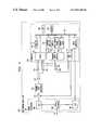
- FIG. 1shows, in simplified block diagram form, a video distribution system employing an embodiment of the invention
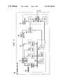
- FIG. 2shows, in simplified block diagram form, details of an ONU ranging delay unit employed in practicing the invention
- FIG. 3shows, in simplified block diagram form, details of an OLC ranging delay unit employed in practicing the invention
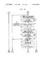
- FIGS. 4A, 4 B and 4 C when connected A—A, B—B, C—C, D—D, E—E and F—Fform a flow chart illustrating the steps in the ranging delay procedure of the ONU ranging delay unit of FIG. 2;
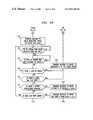
- FIGS. 5A and 5B when connected A—A and B—Bform a flow chart illustrating the steps in the ranging delay procedure of the OLC ranging delay unit of FIG. 3 .
- FIG. 1shows, in simplified block diagram form, a video distribution system employing an embodiment of the invention.
- network 100including video server 101 which supplies downstream video signals to broadband network 102 , in response to an upstream communication including a selection message.
- Broadband network 102supplies the communications signals to and from optical line terminal 103 .
- optical line circuit (OLC) 104interfaces to an optical fiber line.
- the optical fiber lineis, for example, a power splitting passive optical network (PSPON) fiber including optical fibers 110 and 111 on which optical signals are transmitted using coarse wavelength division multiplexing.
- PSPONpower splitting passive optical network
- the PSPON fibers 110may be split into a predetermined number of optical fibers, for example, 32 fibers 111 , thereby interfacing via associated ONUs 106 with 32 locations.
- OLT 103serves one or more OLCs 104 , namely, 104 - 1 through 104 -Z, coupled to a corresponding number of fiber lines, namely, 110 - 1 through 110 -Z, respectively, and that an OLC 104 serves one or more ONUs 106 via optical fibers 111 - 1 through 111 -W.
- the downstream transmission of video signalsis in asynchronous transfer mode (ATM) cells via time division multiplex (TDM), while upstream transmission of communication is via time division multiple access (TDMA), and both downstream and upstream communications is at 155.52 Mb/sec.
- Efficient TDMA communications in the upstream directionrequires all optical network units (ONUs) 106 to have equal loop delay in relationship to their associated OLC 104 .
- Thisis realized by employing a ranging procedure that is executed when each ONU 106 associated with a particular OLC 104 is installed, moved, returned to service, or the like.
- the ranging proceduredefines an artificial delay that when added to the transmission loop delay of an ONU 106 yields the required common loop delay.
- the desired ranging delayis obtained, in this example, by employing a unique out-of-band ranging procedure, in accordance with the invention
- OLT 103is a special ATM switch including a traditional ATM fabric and input/output (I/O) ports.
- I/Oinput/output
- two types of I/O boardsare required, namely, standard SONET (synchronous optical network) boards, e.g., OC-12 units, and OLC boards.
- Video signals received from OLT 103 as ATM cells from one or more SONET boardsare distributed to the OLC boards. Because of this, upstream channel select messages being sent to a video services controller in video server 101 are intercepted within the OLT 103 , which accumulates the number of viewers of each video program that is OLT 103 wide. Only channel (program) selections that are not available within presently received SONET VCs are passed on to the video services controller 202 in video server 101 .
- programprogram
- each of OLC units 104includes, in this example, a CPU and memory that may be a microprocessor with memory, as described below.
- Optical network unit (ONU) 106terminates the PSPON 111 fiber and provides appropriate interfaces, in this example, to one or more television sets (TVs) 107 - 1 through 107 -N.
- TVs 107 - 1 through 107 -Nhas an associated one of remote control (RC) units 108 - 1 through 108 -N, respectively.
- RCremote control
- Network 100supplies, for example, via one or more video services controller units in video server 101 in response to specific program requests, conventional broadcast TV programs, programs similar to those supplied via cable TV providers, satellite TV providers, video on demand and the like. Procedures for requesting and transmitting video programs are described in greater detail below.
- a residential video subsystemincludes an ONU 106 and one or more TVs 107 and associated RC units 108 .
- ONU 106 and TVs 107are interconnected via coaxial (COAX) cable.
- COAXcoaxial
- the desired ranging delayis effected by obtaining a measure of loop delay between an ONU 106 and its associated OLC 104 .
- Thisis realized, in this example, my employing a unique out-of-band ranging arrangement, in accordance with the invention.
- ONU 106includes an ONU ranging delay unit 200 including, in this example, apparatus as shown in FIG. 2 .
- PSPON transceiver 201including PSPON interface 202 for interfacing PSPON optical fiber 111 , in well known fashion.
- Incoming optical signals from PSPON fiber 111are supplied to optical/electrical (O/E) converter 203 where they are converted into electrical signals.
- O/E converter 203optical/electrical converter
- the incoming electrical signalsare supplied to controller 205 and, therein, to input interface 206 .
- Outgoing electrical signalsare converted via electrical/optical (E/O) converter 204 to optical signals.
- the outgoing optical signalsare supplied via PSPON interface 202 to PSPON optical fiber 111 .
- Controller 205includes central processor unit (CPU) 208 which may be a microprocessor, memory 209 , user input/output (I/O) units 210 , status register 211 , assigned time slot register 212 , start of down-stream frame register 213 , ranging delay register 214 , transmit burst control unit 215 and data first-in-first-out (FIFO) register 221 .
- Units 206 , 208 through 215 and 221are interconnected via bus 207 .
- a power ON status signalis supplied to one input of AND gate 216 , while an initialized status signal is supplied to an inhibit input of AND gate 216 , both from status register 211 .
- And gate 216yields a high state output when power ON is a high state and initialized is a low state.
- This high state output from AND gate 216is supplied via OR gate 217 to enable ranging tone oscillator 220 to supply as an output the desired out-of-band ranging tone.
- the ranging stateis effected.
- the out-of-band ranging toneis generated at 466.56 MHz.
- This ranging toneis supplied to summer 222 and, thereafter, to PSPON 111 via E/O 204 and PSPON interface 202 .
- a verify status signalis supplied from status register 211 to an input of AND gate 218 , while a transmit burst control signal is supplied from transmit burst control 215 to a second input of AND gate 218 .
- And gate 218is controlled via the supplied signals to enable transmission of the out-of-band ranging tone during the assigned time slot to effect the verify state.
- An active status signalis supplied from status register 212 to an input of AND gate 219 , the transmit burst control signal is supplied to a second input of AND gate 219 and a clock (CLK) signal is supplied to a third input of AND gate 219 .
- And gateis controlled via the supplied signals to control supplying the CLK signal to data FIFO 221 , thereby enabling the active data state.
- the data output from data FIFO 221is supplied via summer 222 , E/O 204 and PSPON interface 202 to PSPON fiber III.
- FIG. 3shows, in simplified block diagram form, details of an OLC ranging delay unit employed in practicing the invention.
- PSPON transceiver 301including PSPON interface 302 for interfacing PSPON optical fiber 110 , in well known fashion.
- Incoming optical signals from PSPON fiber 110are supplied to optical/electrical (O/E) converter 303 where they are converted into electrical signals.
- O/E converter 303optical/electrical converter 303
- the incoming electrical signalsare supplied to diplexer 306 , which extracts and supplies the in-band data signals to controller 305 and, therein, to I/O 308 .
- Diplexer 306also extracts the out-of-band ranging tone and supplies it to tuned detector 307 .
- a high state output from detector 307 indicating the reception of the out-of-band ranging toneis supplied to one input of AND gate 316 .
- Controller 305includes I/O 308 , CPU 310 , which may be a microprocessor, memory 311 , enable register 312 , reset register 313 , clock 314 and ranging delay register 315 , all interconnected via bus 309 .
- An output from enable register 312is supplied to a second input of AND gate 316 and when it is a high state signal and the high state tone detection signal is present, AND gate 316 supplies an enable high state signal to ranging delay timer 317 . This enables timer 317 to count the clock output from clock 314 . As described below, when the out-of-band ranging tone is no longer detected the count in timer 317 represents the loop delay for a particular ONU associated with this OLC. The loop delay interval is supplied to ranging delay register 315 . A reset signal from reset register initializes ranging delay timer 317 .
- OLC ranging delay unit 300Operation of OLC ranging delay unit 300 is described below in conjunction with the flow chart of FIG. 5 .
- FIGS. 4A, 4 B and 4 C when connected A—A, B—B, C—C, D—D, E—E and F—Fform a flow chart illustrating the steps in the ranging delay procedure of the ONU ranging delay unit of FIG. 2 .
- the ONU 106 ranging delay procedureis begun at 401 .
- step 402tests to determine if ONU power is ON. If the test result is NO, step 402 is repeated until it yields a YES result.
- step 403determines whether the test result in step 403 is NO, ONU 106 has not been initialized and is in the ranging state, and step 404 causes the out-of-band ranging tone to be transmitted.
- the ranging toneis generated at 466.56 MHz, which is outside the normal in-band message transmission band.
- Step 405tests to determine if a broadcast message as been received by ONU 106 . If the test result is NO, step 405 is repeated until a YES result is obtained. Note that the received broadcast message includes an instruction for the ONU to stop transmission of the ranging tone and that the ONU assume an ID. Then, step 406 causes the transmission of the ranging tone to be terminated.
- Step 407sets the ID for ONU 106 to ONUID.
- Step 408tests to determine if a unicast message has been received including the ranging delay determined for the ONUID, namely, “F” which is the number of frames, “B” which is the number of bytes and “b” which is the number of bits.
- Fis a 0, 1 or 2 frame
- Bis between 0 and 2429 bytes, inclusive
- bis between 0 and 7 bits, inclusive.
- Step 409causes the ranging delay for the ONUID to be set to the received values of F, B and b.
- Step 410tests to determine if the up-stream time slot assignment for the ONUID has been received.
- step 410is repeated until it yields a YES result indicating that the assigned time slot identified by its offset and size has been received.
- the offsetis the number of bytes from the start of each frame and the size is the time slot length in bytes.
- Step 411indicates that the unicast message to this ONUID including the assigned time slot has been received and causes the assigned time slot to be set to the received offset and size. Then, this ONU is in the verify state and step 412 causes the transmission of the out-of-band tone in the assigned time slot. Then, step 413 tests to determine if a unicast message to this ONUID has been received. If the test result is NO, step 413 is repeated until it yields a YES result.
- Step 414tests to determine if the received message includes the ranging delay for this ONUID. If the test result is YES, step 415 causes the ranging delay for this ONUID to be set to the received F, B and b. Note that in the verify state, the ranging delay value may be fine tuned through the reception of new values for F, B and b. Thereafter, steps 412 through 415 are iterated until step 414 yields a NO result. Then, step 416 causes the ONU to be set to the data state. Step 417 causes the in-band data burst to be transmitted in the assigned time slot. This is the ONU active data state. Step 418 tests to determine if a unicast message for this ONUID has been received.
- step 418is repeated until it yields a YES result, if at all.
- step 419tests to determine if the received unicast message is switch to verify state. If the test result is YES, the ONU reenters the verify state, control is transferred to step 412 and steps 412 through 419 are iterated until step 419 yields a NO result.
- the verification statemay be reentered because of some particular event being detected in ONU 106 , for example, power failure, or from a control message from OLC 104 .
- step 420causes the assigned time slot to be set to zero (0). This is the ONU idle state.
- Step 421causes the ONU to be set to poll for status timer.
- step 422tests to determine if the status timer has timed-out. If the test result in step 422 is YES, control is transferred to step 408 and appropriate ones of steps 408 through 422 are iterated until step 422 yields a NO result.
- Step 423tests to determine if a unicast message for this ONUID has been received. If the test result is NO, steps 422 and 423 are repeated until either of them yields a YES result. If step 422 yields a YES result, operation is as described above. If step 423 yields a YES result, step 424 tests to determine if the received unicast message is switch to verify state.
- step 412If the test result is YES, control is transferred to step 412 and appropriate ones of steps 412 through 424 are iterated until step 424 yields a NO result. Then, step 425 causes the assigned time slot to be set to a new assigned time slot, namely, a new offset and size. Thereafter, control is transferred to step 417 , appropriate ones of steps 417 through 425 iterated and if necessary appropriate ones of steps 408 through 425 are iterated until the ONU again enters the active data state, i.e., its normal operational state.
- the polled ONCresponds with transmission of the out-of-band ranging tone, that is an indication that the ONU is already in the verify state and the associated OLC treats the ONU as though it was verifying ranging. If the out-of-band tone is properly aligned in the assigned time slot, the ONU is caused to switch to the active data state.
- requiring an idle ONU to be polledenables system operations to distinguish among an idle ONU, a power outage and a relocated ONU, as described below in relationship to the operation of the OLC ranging unit.
- FIGS. 5A and 4B when connected A—A and B—Bform a flow chart illustrating the steps in the ranging delay procedure of the OLC ranging delay unit of FIG. 3 .
- the OLC ranging delay procedureis started in step 501 .
- step 503causes a message to be transmitted to the ONUID causing it to stop transmitting the ranging tone and to assign the ONU ID as ONUID.
- Step 504causes the ranging delay timer to be set.
- step 505tests to determine if the transmission of ranging tone has stopped.
- step 505is repeated until it yields a YES result.
- Step 506causes the ranging delay timer to be stopped.
- the accumulated time interval of the ranging delay timeris the ranging delay for the ONUID. That is, the interval between the terminate transmission of ranging tone message is sent by the OLC and detection that it has terminated is the loop delay for the ONUID.
- step 507causes the transmission of a unicast message to the ONUID including the determined ranging delay, namely, F, B and b.
- Step 508causes the transmission of a message to the ONUID including assignment of an up-stream time slot, namely, offset and size.
- Step 509tests to determine if an out-of band ranging delay tone presently being received in the assigned time slot is aligned with the assigned time slot. If the test result is NO, step 510 causes a message to be transmitted to the ONUID to adjust the ranging delay of the ONUID. Thereafter, step 509 again tests to determine if the out-of-band tone is aligned with the assigned time slot as adjusted. If the test result is NO, steps 510 and 509 are iterated until step 509 yields a YES result. Then, step 511 causes a message to be transmitted to the ONUID indicating that the ONU switch to the active data state. Step 512 tests to determine if up-stream data is being received from any ONU associated with this OLC.
- step 512is repeated until it yields a YES result.
- step 513tests to determine if the data is in the proper time slot assigned to ONUID transmitting the data. If the test result is YES step 513 is repeated until it yields a NO result.
- Step 514tests to determine if there is a loss of signal. If the test result is YES, step 515 causes a message to be transmitted to the ONUID switching it to the verify state. Then, control is transferred to step 508 and appropriate ones of steps 508 through 515 are iterated until step 514 yields a NO result.
- Step 516tests to determine if there is a large time slot drift.
- step 515tests to determine if there is a severe unadjustable problem. If the test result is YES, step 518 causes a message to be transmitted to the ONUID causing it to enter the uninitialized state.
- step 519tests to determine if the time slot drift is minor. If the test result is NO, control is returned to step 512 and appropriate ones of steps 512 through 519 are iterated, and if necessary appropriate ones of steps 508 through 519 are iterated, until step 519 yields a YES result. Then, step 520 causes a message to be transmitted to the ONUID including a new ranging delay, namely, a new F, B and b.
- a so-called “self-aware” systemmust re-establish a correct state of operation of the one or more associated ONUs automatically when power is restored.
- An ONU that loses powerstops transmitting data and reverts to the verify state.
- the associated OLCdetects the “loss of signal” from the one or more ONU that lost power, and deletes them from a list of up-stream time slot assignments. Then, the list of ONCs that are not in the active state are polled, as described above. Consequently, when power is restored, the ONUs are brought on-line one at a time.
- an ONUIf an ONU is moved or otherwise disconnected, it is placed into the un-iniatilized state by clearing its ranging delay. When the ONU is reconnected, it will automatically initiate the ranging procedure, as described above.
- an ONUcan be disconnected or moved without prior knowledge of the system operators. For example, an ONU can be disconnected and, then, reconnected at some other location without notification to the system operators. When the ONU is disconnected it loses power and switches to the verify state, as described above. When an attempt is made to reconnect and reactivate the ONU, however, its out-of-band ranging tone will be positioned incorrectly in the up-stream frame. That is, the out-of-band tone will be in the wrong time slot. Because of this, the associated OLC generates a message and send it to the ONU, which resets the ONC to the un-initialized state. This, in turn, results in the automatic activation of the ranging procedure. That is, the ONU is treated as a newly connected ONU.
- out-of-band ranginghas no impact on up-stream bandwidth management, i.e., it is non-intrusive. Additionally, the probability of a “ranging” collision is minimized because an ONU ranges immediately upon it being connected to the network and powered on. Moreover, an out-of-band ranging tone offers additional capabilities for non-intrusive verification, handling power outages, switching an ONU to a low power standby state and ONU location moves, as described above.
Landscapes
- Engineering & Computer Science (AREA)
- Signal Processing (AREA)
- Computer Networks & Wireless Communication (AREA)
- Multimedia (AREA)
- Small-Scale Networks (AREA)
- Time-Division Multiplex Systems (AREA)
Abstract
Description
Claims (50)
Priority Applications (3)
| Application Number | Priority Date | Filing Date | Title |
|---|---|---|---|
| US09/356,980US6807188B1 (en) | 1999-07-19 | 1999-07-19 | Ranging arrangement and method for TDMA communications |
| JP2000217060AJP4652532B2 (en) | 1999-07-19 | 2000-07-18 | TDMA communication apparatus and communication method thereof |
| US10/897,914US7366196B2 (en) | 1999-07-19 | 2004-07-23 | Ranging arrangement and method for TDMA communications |
Applications Claiming Priority (1)
| Application Number | Priority Date | Filing Date | Title |
|---|---|---|---|
| US09/356,980US6807188B1 (en) | 1999-07-19 | 1999-07-19 | Ranging arrangement and method for TDMA communications |
Related Child Applications (1)
| Application Number | Title | Priority Date | Filing Date |
|---|---|---|---|
| US10/897,914DivisionUS7366196B2 (en) | 1999-07-19 | 2004-07-23 | Ranging arrangement and method for TDMA communications |
Publications (1)
| Publication Number | Publication Date |
|---|---|
| US6807188B1true US6807188B1 (en) | 2004-10-19 |
Family
ID=23403793
Family Applications (2)
| Application Number | Title | Priority Date | Filing Date |
|---|---|---|---|
| US09/356,980Expired - LifetimeUS6807188B1 (en) | 1999-07-19 | 1999-07-19 | Ranging arrangement and method for TDMA communications |
| US10/897,914Expired - LifetimeUS7366196B2 (en) | 1999-07-19 | 2004-07-23 | Ranging arrangement and method for TDMA communications |
Family Applications After (1)
| Application Number | Title | Priority Date | Filing Date |
|---|---|---|---|
| US10/897,914Expired - LifetimeUS7366196B2 (en) | 1999-07-19 | 2004-07-23 | Ranging arrangement and method for TDMA communications |
Country Status (2)
| Country | Link |
|---|---|
| US (2) | US6807188B1 (en) |
| JP (1) | JP4652532B2 (en) |
Cited By (31)
| Publication number | Priority date | Publication date | Assignee | Title |
|---|---|---|---|---|
| US20030016692A1 (en)* | 2000-10-26 | 2003-01-23 | Wave7 Optics, Inc. | Method and system for processing upstream packets of an optical network |
| US20040264492A1 (en)* | 1999-07-19 | 2004-12-30 | Blahut Donald E. | Ranging arrangement and method for TDMA communications |
| US20050249498A1 (en)* | 2002-09-13 | 2005-11-10 | Onn Haran | Operations method in an ethernet passive optical network that includes a network unit with multiple entities |
| US20060072520A1 (en)* | 2000-03-23 | 2006-04-06 | Chitrapu Prabhakar R | Time synchronized standby state to the GPRS medium access control protocol with applications to mobile satellite systems |
| US20060256811A1 (en)* | 2005-05-11 | 2006-11-16 | Hitachi Communication Technologies, Ltd. | ATM-PON system and ONU automatic connection method |
| US7218855B2 (en) | 2001-07-05 | 2007-05-15 | Wave7 Optics, Inc. | System and method for communicating optical signals to multiple subscribers having various bandwidth demands connected to the same optical waveguide |
| US20070237188A1 (en)* | 2006-04-05 | 2007-10-11 | Miguel Joseph D | Method and apparatus for ONT ranging with improved noise immunity |
| US20070237523A1 (en)* | 2006-04-05 | 2007-10-11 | Tellabs Petaluma, Inc. | Method and apparatus for diagnosing problems on a time division multiple access (TDMA) optical distribution network (ODN) |
| US20070237189A1 (en)* | 2006-04-05 | 2007-10-11 | Tellabs Petaluma, Inc. | Method and apparatus for ONT ranging with improved noise immunity |
| US20070237520A1 (en)* | 2006-04-05 | 2007-10-11 | Delew David A | Methods and apparatus for identifying a passive optical network failure |
| US20070264016A1 (en)* | 2006-04-21 | 2007-11-15 | Tellabs Petaluma, Inc. | Method and apparatus for rogue tolerant ranging and detection |
| WO2007123692A3 (en)* | 2006-04-05 | 2008-02-14 | Tellabs Petaluma Inc | Detecting and minimizing effects of optical network faults |
| US7340180B2 (en) | 2004-08-10 | 2008-03-04 | Wave7 Optics, Inc. | Countermeasures for idle pattern SRS interference in ethernet optical network systems |
| US7355848B1 (en) | 2002-01-07 | 2008-04-08 | Wave7 Optics, Inc. | System and method for removing heat from a subscriber optical interface |
| US7389031B2 (en) | 2002-10-15 | 2008-06-17 | Wave7 Optics, Inc. | Reflection suppression for an optical fiber |
| US7454141B2 (en) | 2003-03-14 | 2008-11-18 | Enablence Usa Fttx Networks Inc. | Method and system for providing a return path for signals generated by legacy terminals in an optical network |
| US7529485B2 (en) | 2001-07-05 | 2009-05-05 | Enablence Usa Fttx Networks, Inc. | Method and system for supporting multiple services with a subscriber optical interface located outside a subscriber's premises |
| US7583897B2 (en) | 2002-01-08 | 2009-09-01 | Enablence Usa Fttx Networks Inc. | Optical network system and method for supporting upstream signals propagated according to a cable modem protocol |
| US7593639B2 (en) | 2001-08-03 | 2009-09-22 | Enablence Usa Fttx Networks Inc. | Method and system for providing a return path for signals generated by legacy terminals in an optical network |
| US7599622B2 (en) | 2004-08-19 | 2009-10-06 | Enablence Usa Fttx Networks Inc. | System and method for communicating optical signals between a data service provider and subscribers |
| US7606492B2 (en) | 2000-10-04 | 2009-10-20 | Enablence Usa Fttx Networks Inc. | System and method for communicating optical signals upstream and downstream between a data service provider and subscribers |
| US7616901B2 (en) | 2005-08-10 | 2009-11-10 | Enablence Usa Fttx Networks Inc. | Countermeasures for idle pattern SRS interference in ethernet optical network systems |
| US7623786B2 (en)* | 2002-05-20 | 2009-11-24 | Enablence Usa Fttx Networks, Inc. | System and method for communicating optical signals to multiple subscribers having various bandwidth demands connected to the same optical waveguide |
| US7676156B2 (en)* | 2001-06-25 | 2010-03-09 | Alcatel-Lucent Usa Inc. | Method and system for multiplexed optical information transport |
| US7877014B2 (en) | 2001-07-05 | 2011-01-25 | Enablence Technologies Inc. | Method and system for providing a return path for signals generated by legacy video service terminals in an optical network |
| US20140270753A1 (en)* | 2013-03-13 | 2014-09-18 | Tellabs Operations, Inc. | Method and system for communicating with remote equipment |
| US20170288716A1 (en)* | 2016-03-31 | 2017-10-05 | Corning Optical Communications Wireless Ltd | Reducing out-of-channel noise in a wireless distribution system (wds) |
| US9807700B2 (en) | 2015-02-19 | 2017-10-31 | Corning Optical Communications Wireless Ltd | Offsetting unwanted downlink interference signals in an uplink path in a distributed antenna system (DAS) |
| US10193652B2 (en)* | 2015-07-09 | 2019-01-29 | Mitsubishi Electric Corporation | Method and master device for controlling access to out-of-band communication channel in optical communications network |
| US10231016B2 (en)* | 2014-09-11 | 2019-03-12 | Electronics And Telecommunications Research Institute | Network cooperation-based low power type charged broadcasting set-top box and controlling method therefor |
| US20190327541A1 (en)* | 2016-12-02 | 2019-10-24 | Zte Corporation | Passive optical network system and implementation method thereof |
Families Citing this family (7)
| Publication number | Priority date | Publication date | Assignee | Title |
|---|---|---|---|---|
| JP3936721B2 (en)* | 2005-07-29 | 2007-06-27 | 株式会社日立コミュニケーションテクノロジー | Optical access system, optical subscriber unit and optical concentrator |
| US7805881B2 (en) | 2007-05-14 | 2010-10-05 | Patrick John Kavanaugh | Bead attachment |
| WO2009112083A1 (en)* | 2008-03-11 | 2009-09-17 | Telefonaktiebolaget Lm Ericsson (Publ) | Improved optical access network and nodes |
| EP2313992A4 (en)* | 2008-08-15 | 2014-09-17 | Unwired Planet Internat Ltd | Relative time division for network coding |
| US8849121B2 (en)* | 2008-09-12 | 2014-09-30 | Telefonaktiebolaget L M Ericsson (Publ) | Scheduling device |
| US8245029B2 (en)* | 2008-10-31 | 2012-08-14 | Fujitsu Limited | System and method for enhanced network entrance into a wireless network |
| EP2475121A1 (en)* | 2011-01-10 | 2012-07-11 | Ntt Docomo, Inc. | Communication system and method for directly transmitting signals between nodes of a communication system |
Citations (4)
| Publication number | Priority date | Publication date | Assignee | Title |
|---|---|---|---|---|
| US6307868B1 (en)* | 1995-08-25 | 2001-10-23 | Terayon Communication Systems, Inc. | Apparatus and method for SCDMA digital data transmission using orthogonal codes and a head end modem with no tracking loops |
| US6356555B1 (en)* | 1995-08-25 | 2002-03-12 | Terayon Communications Systems, Inc. | Apparatus and method for digital data transmission using orthogonal codes |
| US6507592B1 (en)* | 1999-07-08 | 2003-01-14 | Cisco Cable Products And Solutions A/S (Av) | Apparatus and a method for two-way data communication |
| US6665308B1 (en)* | 1995-08-25 | 2003-12-16 | Terayon Communication Systems, Inc. | Apparatus and method for equalization in distributed digital data transmission systems |
Family Cites Families (4)
| Publication number | Priority date | Publication date | Assignee | Title |
|---|---|---|---|---|
| JPH1093607A (en)* | 1996-09-18 | 1998-04-10 | Toshiba Corp | Communications system |
| EP0891085A1 (en)* | 1997-07-10 | 1999-01-13 | Alcatel | A method to provide information concerning a frequency band, a head-end and a terminal realizing such a method and a communication access network including such a head-end and such a terminal |
| EP0891087B1 (en)* | 1997-07-10 | 2008-12-10 | Alcatel Lucent | Method, apparatuses and network to determine an access frequency band |
| US6807188B1 (en)* | 1999-07-19 | 2004-10-19 | Lucent Technologies Inc. | Ranging arrangement and method for TDMA communications |
- 1999
- 1999-07-19USUS09/356,980patent/US6807188B1/ennot_activeExpired - Lifetime
- 2000
- 2000-07-18JPJP2000217060Apatent/JP4652532B2/ennot_activeExpired - Fee Related
- 2004
- 2004-07-23USUS10/897,914patent/US7366196B2/ennot_activeExpired - Lifetime
Patent Citations (4)
| Publication number | Priority date | Publication date | Assignee | Title |
|---|---|---|---|---|
| US6307868B1 (en)* | 1995-08-25 | 2001-10-23 | Terayon Communication Systems, Inc. | Apparatus and method for SCDMA digital data transmission using orthogonal codes and a head end modem with no tracking loops |
| US6356555B1 (en)* | 1995-08-25 | 2002-03-12 | Terayon Communications Systems, Inc. | Apparatus and method for digital data transmission using orthogonal codes |
| US6665308B1 (en)* | 1995-08-25 | 2003-12-16 | Terayon Communication Systems, Inc. | Apparatus and method for equalization in distributed digital data transmission systems |
| US6507592B1 (en)* | 1999-07-08 | 2003-01-14 | Cisco Cable Products And Solutions A/S (Av) | Apparatus and a method for two-way data communication |
Cited By (49)
| Publication number | Priority date | Publication date | Assignee | Title |
|---|---|---|---|---|
| US20040264492A1 (en)* | 1999-07-19 | 2004-12-30 | Blahut Donald E. | Ranging arrangement and method for TDMA communications |
| US7366196B2 (en)* | 1999-07-19 | 2008-04-29 | Lucent Technologies Inc. | Ranging arrangement and method for TDMA communications |
| US20060072520A1 (en)* | 2000-03-23 | 2006-04-06 | Chitrapu Prabhakar R | Time synchronized standby state to the GPRS medium access control protocol with applications to mobile satellite systems |
| US7606492B2 (en) | 2000-10-04 | 2009-10-20 | Enablence Usa Fttx Networks Inc. | System and method for communicating optical signals upstream and downstream between a data service provider and subscribers |
| US7085281B2 (en)* | 2000-10-26 | 2006-08-01 | Wave7 Optics, Inc. | Method and system for processing upstream packets of an optical network |
| US20030016692A1 (en)* | 2000-10-26 | 2003-01-23 | Wave7 Optics, Inc. | Method and system for processing upstream packets of an optical network |
| US7676156B2 (en)* | 2001-06-25 | 2010-03-09 | Alcatel-Lucent Usa Inc. | Method and system for multiplexed optical information transport |
| US7877014B2 (en) | 2001-07-05 | 2011-01-25 | Enablence Technologies Inc. | Method and system for providing a return path for signals generated by legacy video service terminals in an optical network |
| US7218855B2 (en) | 2001-07-05 | 2007-05-15 | Wave7 Optics, Inc. | System and method for communicating optical signals to multiple subscribers having various bandwidth demands connected to the same optical waveguide |
| US7529485B2 (en) | 2001-07-05 | 2009-05-05 | Enablence Usa Fttx Networks, Inc. | Method and system for supporting multiple services with a subscriber optical interface located outside a subscriber's premises |
| US7593639B2 (en) | 2001-08-03 | 2009-09-22 | Enablence Usa Fttx Networks Inc. | Method and system for providing a return path for signals generated by legacy terminals in an optical network |
| US7355848B1 (en) | 2002-01-07 | 2008-04-08 | Wave7 Optics, Inc. | System and method for removing heat from a subscriber optical interface |
| US7583897B2 (en) | 2002-01-08 | 2009-09-01 | Enablence Usa Fttx Networks Inc. | Optical network system and method for supporting upstream signals propagated according to a cable modem protocol |
| US7623786B2 (en)* | 2002-05-20 | 2009-11-24 | Enablence Usa Fttx Networks, Inc. | System and method for communicating optical signals to multiple subscribers having various bandwidth demands connected to the same optical waveguide |
| US8189598B2 (en) | 2002-09-13 | 2012-05-29 | Pmc-Sierra Israel Ltd. | Operations method in an ethernet passive optical network that includes a network unit with multiple entities |
| US7688843B2 (en)* | 2002-09-13 | 2010-03-30 | Pmc-Sierra Israel Ltd. | Operations method in an ethernet passive optical network that includes a network unit with multiple entities |
| US20100208745A1 (en)* | 2002-09-13 | 2010-08-19 | Pmc-Sierra Israel Ltd. | Operations method in an ethernet passive optical network that includes a network unit with multiple entities |
| US20050249498A1 (en)* | 2002-09-13 | 2005-11-10 | Onn Haran | Operations method in an ethernet passive optical network that includes a network unit with multiple entities |
| US8526431B2 (en) | 2002-09-13 | 2013-09-03 | Pmc-Sierra Israel Ltd. | Operation methods in an ethernet passive optical network that includes a network unit with multiple entities |
| US7389031B2 (en) | 2002-10-15 | 2008-06-17 | Wave7 Optics, Inc. | Reflection suppression for an optical fiber |
| US8682162B2 (en)* | 2003-03-14 | 2014-03-25 | Aurora Networks, Inc. | Method and system for providing a return path for signals generated by legacy terminals in an optical network |
| US7454141B2 (en) | 2003-03-14 | 2008-11-18 | Enablence Usa Fttx Networks Inc. | Method and system for providing a return path for signals generated by legacy terminals in an optical network |
| US20120057877A1 (en)* | 2003-03-14 | 2012-03-08 | Enablence Usa Fttx Networks Inc. | Method and system for providing a return path for signals generated by legacy terminals in an optical network |
| US7986880B2 (en) | 2003-03-14 | 2011-07-26 | Enablence Usa Fttx Networks Inc. | Method and system for providing a return path for signals generated by legacy terminals in an optical network |
| US7340180B2 (en) | 2004-08-10 | 2008-03-04 | Wave7 Optics, Inc. | Countermeasures for idle pattern SRS interference in ethernet optical network systems |
| US7599622B2 (en) | 2004-08-19 | 2009-10-06 | Enablence Usa Fttx Networks Inc. | System and method for communicating optical signals between a data service provider and subscribers |
| US20100046947A1 (en)* | 2004-08-19 | 2010-02-25 | Enablence Usa Fttx Networks Inc. | System and method for communicating optical signals between a data service provider and subscribers |
| US7953325B2 (en)* | 2004-08-19 | 2011-05-31 | Enablence Usa Fttx Networks, Inc. | System and method for communicating optical signals between a data service provider and subscribers |
| US7738463B2 (en)* | 2005-05-11 | 2010-06-15 | Hitachi, Ltd. | ATM-PON system and ONU automatic connection method |
| US20060256811A1 (en)* | 2005-05-11 | 2006-11-16 | Hitachi Communication Technologies, Ltd. | ATM-PON system and ONU automatic connection method |
| US7616901B2 (en) | 2005-08-10 | 2009-11-10 | Enablence Usa Fttx Networks Inc. | Countermeasures for idle pattern SRS interference in ethernet optical network systems |
| US7881607B2 (en)* | 2006-04-05 | 2011-02-01 | Tellabs Petaluma, Inc. | Methods and apparatus for identifying a passive optical network failure |
| US20070237523A1 (en)* | 2006-04-05 | 2007-10-11 | Tellabs Petaluma, Inc. | Method and apparatus for diagnosing problems on a time division multiple access (TDMA) optical distribution network (ODN) |
| US8095002B2 (en) | 2006-04-05 | 2012-01-10 | Tellabs Pataluma, Inc. | Method and apparatus for diagnosing problems on a time division multiple network access (TDMA) optical distribution network (ODN) |
| US20070237189A1 (en)* | 2006-04-05 | 2007-10-11 | Tellabs Petaluma, Inc. | Method and apparatus for ONT ranging with improved noise immunity |
| US20070237520A1 (en)* | 2006-04-05 | 2007-10-11 | Delew David A | Methods and apparatus for identifying a passive optical network failure |
| WO2007123692A3 (en)* | 2006-04-05 | 2008-02-14 | Tellabs Petaluma Inc | Detecting and minimizing effects of optical network faults |
| US20070237188A1 (en)* | 2006-04-05 | 2007-10-11 | Miguel Joseph D | Method and apparatus for ONT ranging with improved noise immunity |
| US20070264016A1 (en)* | 2006-04-21 | 2007-11-15 | Tellabs Petaluma, Inc. | Method and apparatus for rogue tolerant ranging and detection |
| US20140270753A1 (en)* | 2013-03-13 | 2014-09-18 | Tellabs Operations, Inc. | Method and system for communicating with remote equipment |
| US10231016B2 (en)* | 2014-09-11 | 2019-03-12 | Electronics And Telecommunications Research Institute | Network cooperation-based low power type charged broadcasting set-top box and controlling method therefor |
| US9807700B2 (en) | 2015-02-19 | 2017-10-31 | Corning Optical Communications Wireless Ltd | Offsetting unwanted downlink interference signals in an uplink path in a distributed antenna system (DAS) |
| US10193652B2 (en)* | 2015-07-09 | 2019-01-29 | Mitsubishi Electric Corporation | Method and master device for controlling access to out-of-band communication channel in optical communications network |
| US20170288716A1 (en)* | 2016-03-31 | 2017-10-05 | Corning Optical Communications Wireless Ltd | Reducing out-of-channel noise in a wireless distribution system (wds) |
| US10236924B2 (en)* | 2016-03-31 | 2019-03-19 | Corning Optical Communications Wireless Ltd | Reducing out-of-channel noise in a wireless distribution system (WDS) |
| US20190181898A1 (en)* | 2016-03-31 | 2019-06-13 | Corning Optical Communications LLC | Reducing out-of-channel noise in a wireless distribution system (wds) |
| US10530408B2 (en)* | 2016-03-31 | 2020-01-07 | Corning Optical Communications LLC | Reducing out-of-channel noise in a wireless distribution system (WDS) |
| US20190327541A1 (en)* | 2016-12-02 | 2019-10-24 | Zte Corporation | Passive optical network system and implementation method thereof |
| US10798473B2 (en)* | 2016-12-02 | 2020-10-06 | Zte Corporation | Passive optical network system and implementation method thereof |
Also Published As
| Publication number | Publication date |
|---|---|
| US7366196B2 (en) | 2008-04-29 |
| US20040264492A1 (en) | 2004-12-30 |
| JP4652532B2 (en) | 2011-03-16 |
| JP2001069102A (en) | 2001-03-16 |
Similar Documents
| Publication | Publication Date | Title |
|---|---|---|
| US6807188B1 (en) | Ranging arrangement and method for TDMA communications | |
| US8849121B2 (en) | Scheduling device | |
| EP1071288B1 (en) | Video controller | |
| JP3598952B2 (en) | ATM-PON duplex system, office-side optical network terminator, subscriber-side optical network terminator, and ATM-PON duplex method | |
| US4512033A (en) | Remote level adjustment system for use in a multi-terminal communications system | |
| AU673415B2 (en) | A wide area fiber and TV cable fast packet cell network | |
| CA2219524C (en) | Method, device and data communication system for multilink polling | |
| US6078589A (en) | Method and arrangements for the optimal use of switching--oriented and transmission--oriented resources of multimedia communication networks | |
| US7961719B2 (en) | End of line monitor using DOCSIS | |
| CA2214651C (en) | Optical network | |
| EP1178698B1 (en) | Unused bandwidth allocation in passive optical networks | |
| EP0748574A1 (en) | Communications system | |
| NZ247381A (en) | Optical connection network | |
| JP7424385B2 (en) | Communication equipment and power usage method | |
| JP3698210B2 (en) | Packet communication system, packet communication method, packet communication program, and recording medium recording the packet communication program | |
| US6801547B1 (en) | Ranging cell detection in a noisy environment | |
| EP1181822A1 (en) | Establishment of upstream connection in wired network | |
| US11012257B2 (en) | Home side device and method of clearing management table | |
| KR100819265B1 (en) | Optical subscriber device and control method in passive optical subscriber network | |
| KR0183924B1 (en) | Data channel loop back test device | |
| KR20020080439A (en) | Dual rate periodic ranging system to reduce time to ascertain cable modem failure | |
| KR100404853B1 (en) | Method for automatically releasing session of video on demand system | |
| CN116614736A (en) | Ethernet distributed access system | |
| KR20000045604A (en) | Satellite accessing device and method in satellite multimedia system | |
| JPH02104045A (en) | Automatic adjustment method of transmission output |
Legal Events
| Date | Code | Title | Description |
|---|---|---|---|
| AS | Assignment | Owner name:LUCENT TECHNOLOGIES INC., NEW JERSEY Free format text:ASSIGNMENT OF ASSIGNORS INTEREST;ASSIGNORS:BLAHUT, DONALD E.;MAGILL, PETER D.;REEL/FRAME:010232/0201 Effective date:19990903 | |
| FEPP | Fee payment procedure | Free format text:PAYOR NUMBER ASSIGNED (ORIGINAL EVENT CODE: ASPN); ENTITY STATUS OF PATENT OWNER: LARGE ENTITY | |
| STCF | Information on status: patent grant | Free format text:PATENTED CASE | |
| FPAY | Fee payment | Year of fee payment:4 | |
| FPAY | Fee payment | Year of fee payment:8 | |
| AS | Assignment | Owner name:CREDIT SUISSE AG, NEW YORK Free format text:SECURITY INTEREST;ASSIGNOR:ALCATEL-LUCENT USA INC.;REEL/FRAME:030510/0627 Effective date:20130130 | |
| AS | Assignment | Owner name:ALCATEL-LUCENT USA INC., NEW JERSEY Free format text:RELEASE BY SECURED PARTY;ASSIGNOR:CREDIT SUISSE AG;REEL/FRAME:033949/0531 Effective date:20140819 | |
| FPAY | Fee payment | Year of fee payment:12 | |
| AS | Assignment | Owner name:PROVENANCE ASSET GROUP LLC, CONNECTICUT Free format text:ASSIGNMENT OF ASSIGNORS INTEREST;ASSIGNORS:NOKIA TECHNOLOGIES OY;NOKIA SOLUTIONS AND NETWORKS BV;ALCATEL LUCENT SAS;REEL/FRAME:043877/0001 Effective date:20170912 Owner name:NOKIA USA INC., CALIFORNIA Free format text:SECURITY INTEREST;ASSIGNORS:PROVENANCE ASSET GROUP HOLDINGS, LLC;PROVENANCE ASSET GROUP LLC;REEL/FRAME:043879/0001 Effective date:20170913 Owner name:CORTLAND CAPITAL MARKET SERVICES, LLC, ILLINOIS Free format text:SECURITY INTEREST;ASSIGNORS:PROVENANCE ASSET GROUP HOLDINGS, LLC;PROVENANCE ASSET GROUP, LLC;REEL/FRAME:043967/0001 Effective date:20170913 | |
| AS | Assignment | Owner name:ALCATEL-LUCENT USA INC., NEW JERSEY Free format text:CHANGE OF NAME;ASSIGNOR:LUCENT TECHNOLOGIES INC.;REEL/FRAME:049887/0613 Effective date:20081101 | |
| AS | Assignment | Owner name:NOKIA US HOLDINGS INC., NEW JERSEY Free format text:ASSIGNMENT AND ASSUMPTION AGREEMENT;ASSIGNOR:NOKIA USA INC.;REEL/FRAME:048370/0682 Effective date:20181220 | |
| AS | Assignment | Owner name:PROVENANCE ASSET GROUP LLC, CONNECTICUT Free format text:RELEASE BY SECURED PARTY;ASSIGNOR:CORTLAND CAPITAL MARKETS SERVICES LLC;REEL/FRAME:058983/0104 Effective date:20211101 Owner name:PROVENANCE ASSET GROUP HOLDINGS LLC, CONNECTICUT Free format text:RELEASE BY SECURED PARTY;ASSIGNOR:CORTLAND CAPITAL MARKETS SERVICES LLC;REEL/FRAME:058983/0104 Effective date:20211101 Owner name:PROVENANCE ASSET GROUP LLC, CONNECTICUT Free format text:RELEASE BY SECURED PARTY;ASSIGNOR:NOKIA US HOLDINGS INC.;REEL/FRAME:058363/0723 Effective date:20211129 Owner name:PROVENANCE ASSET GROUP HOLDINGS LLC, CONNECTICUT Free format text:RELEASE BY SECURED PARTY;ASSIGNOR:NOKIA US HOLDINGS INC.;REEL/FRAME:058363/0723 Effective date:20211129 | |
| AS | Assignment | Owner name:RPX CORPORATION, CALIFORNIA Free format text:ASSIGNMENT OF ASSIGNORS INTEREST;ASSIGNOR:PROVENANCE ASSET GROUP LLC;REEL/FRAME:059352/0001 Effective date:20211129 |