US6806469B2 - Enhanced vision system sensitive to infrared radiation - Google Patents
Enhanced vision system sensitive to infrared radiationDownload PDFInfo
- Publication number
- US6806469B2 US6806469B2US10/123,539US12353902AUS6806469B2US 6806469 B2US6806469 B2US 6806469B2US 12353902 AUS12353902 AUS 12353902AUS 6806469 B2US6806469 B2US 6806469B2
- Authority
- US
- United States
- Prior art keywords
- image signal
- vision system
- detected
- detected image
- signal
- Prior art date
- Legal status (The legal status is an assumption and is not a legal conclusion. Google has not performed a legal analysis and makes no representation as to the accuracy of the status listed.)
- Expired - Lifetime
Links
Images


Classifications
- H—ELECTRICITY
- H10—SEMICONDUCTOR DEVICES; ELECTRIC SOLID-STATE DEVICES NOT OTHERWISE PROVIDED FOR
- H10F—INORGANIC SEMICONDUCTOR DEVICES SENSITIVE TO INFRARED RADIATION, LIGHT, ELECTROMAGNETIC RADIATION OF SHORTER WAVELENGTH OR CORPUSCULAR RADIATION
- H10F39/00—Integrated devices, or assemblies of multiple devices, comprising at least one element covered by group H10F30/00, e.g. radiation detectors comprising photodiode arrays
- H10F39/10—Integrated devices
- H10F39/12—Image sensors
- H10F39/18—Complementary metal-oxide-semiconductor [CMOS] image sensors; Photodiode array image sensors
- H10F39/184—Infrared image sensors
- B—PERFORMING OPERATIONS; TRANSPORTING
- B64—AIRCRAFT; AVIATION; COSMONAUTICS
- B64D—EQUIPMENT FOR FITTING IN OR TO AIRCRAFT; FLIGHT SUITS; PARACHUTES; ARRANGEMENT OR MOUNTING OF POWER PLANTS OR PROPULSION TRANSMISSIONS IN AIRCRAFT
- B64D43/00—Arrangements or adaptations of instruments
- B—PERFORMING OPERATIONS; TRANSPORTING
- B64—AIRCRAFT; AVIATION; COSMONAUTICS
- B64D—EQUIPMENT FOR FITTING IN OR TO AIRCRAFT; FLIGHT SUITS; PARACHUTES; ARRANGEMENT OR MOUNTING OF POWER PLANTS OR PROPULSION TRANSMISSIONS IN AIRCRAFT
- B64D45/00—Aircraft indicators or protectors not otherwise provided for
- B64D45/04—Landing aids; Safety measures to prevent collision with earth's surface
- B64D45/08—Landing aids; Safety measures to prevent collision with earth's surface optical
- G—PHYSICS
- G01—MEASURING; TESTING
- G01C—MEASURING DISTANCES, LEVELS OR BEARINGS; SURVEYING; NAVIGATION; GYROSCOPIC INSTRUMENTS; PHOTOGRAMMETRY OR VIDEOGRAMMETRY
- G01C21/00—Navigation; Navigational instruments not provided for in groups G01C1/00 - G01C19/00
- G01C21/20—Instruments for performing navigational calculations
- G—PHYSICS
- G06—COMPUTING OR CALCULATING; COUNTING
- G06T—IMAGE DATA PROCESSING OR GENERATION, IN GENERAL
- G06T1/00—General purpose image data processing
- G06T1/20—Processor architectures; Processor configuration, e.g. pipelining
- G—PHYSICS
- G08—SIGNALLING
- G08G—TRAFFIC CONTROL SYSTEMS
- G08G5/00—Traffic control systems for aircraft
- G08G5/20—Arrangements for acquiring, generating, sharing or displaying traffic information
- G08G5/21—Arrangements for acquiring, generating, sharing or displaying traffic information located onboard the aircraft
- G—PHYSICS
- G08—SIGNALLING
- G08G—TRAFFIC CONTROL SYSTEMS
- G08G5/00—Traffic control systems for aircraft
- G08G5/50—Navigation or guidance aids
- G08G5/54—Navigation or guidance aids for approach or landing
- H—ELECTRICITY
- H04—ELECTRIC COMMUNICATION TECHNIQUE
- H04N—PICTORIAL COMMUNICATION, e.g. TELEVISION
- H04N23/00—Cameras or camera modules comprising electronic image sensors; Control thereof
- H04N23/20—Cameras or camera modules comprising electronic image sensors; Control thereof for generating image signals from infrared radiation only
- B—PERFORMING OPERATIONS; TRANSPORTING
- B64—AIRCRAFT; AVIATION; COSMONAUTICS
- B64D—EQUIPMENT FOR FITTING IN OR TO AIRCRAFT; FLIGHT SUITS; PARACHUTES; ARRANGEMENT OR MOUNTING OF POWER PLANTS OR PROPULSION TRANSMISSIONS IN AIRCRAFT
- B64D45/00—Aircraft indicators or protectors not otherwise provided for
- B64D2045/0075—Adaptations for use of electronic flight bags in aircraft; Supports therefor in the cockpit
Definitions
- the present inventionrelates generally to machine vision systems and, more specifically, to an enhanced vision system (EVS) for use in the piloting of aircraft.
- EVSenhanced vision system
- the invented systemuses detectors sensitive to infrared radiation to generate a navigational display, preferably graphically representing the surrounding background scene such as terrain and structures, selected navigational references sensed by the EVS, and related information from other components of the overall navigation system for an aircraft.
- the preferred graphical representationis a fusion of enhanced, realistic camera images with computer-generated, scene-depicting symbology that is particularly helpful during approach and landing of an aircraft.
- Vision systemsare particularly valuable for the piloting of aircraft because aircraft are expected to fly in very diverse weather conditions, and because any error in navigating an aircraft can have extremely dire consequences. Poor visibility is often associated with flying in fog, but other atmospheric conditions severely limit visibility, including snow, rain, smoke, and ash. Discussion of the optical characteristics of the atmosphere and their impact on what is known as runway visual range is found in David C. Burnham et al., “United States Experience Using Forward Scattermeters for Runway Visual Range,” U.S. Department of Transportation Report No. DOT/FAA/AND-97/1 DOT-VNTSC-FAA-97-1 (March, 1997), the disclosures of which are incorporated herein by reference.
- the generated imagery of the present EVSmay be displayed on a head-up display, but head-down or other displays are within the scope of this invention.
- Head-up displaystypically are used for pilot control of an aircraft during landing
- head-down displaystypically are used for pilot monitoring of automatic landing system performance.
- the vision system of the present inventionpreferably generates a display based on a fusion of images from two imagers.
- One of the imagerssenses short-wavelength infrared radiation (SWIR), and the other senses long- or medium-wavelength infrared radiation (LWIR or MWIR).
- SWIRshort-wavelength infrared radiation
- LWIR or MWIRmedium-wavelength infrared radiation
- Each imagerincludes a detector and electronics to process a signal produced by the detector.
- the imagersmay share optics, or may each have separate optics.
- the imagersare described as separate items because this is believed the best way to implement the invention using current detector and optics components. However, the imagers or selected components of the imagers may be integrated into a single optics/detector/electronics devices in the future. For example, several of the incorporated patents disclose integrated detector devices, sensitive to two separate ranges of radiation.
- a broad dynamic rangemay be allocated to the signal generated by each of the detectors, without concern for the dynamic range required by the other of the detectors.
- Signal conditioning and processing by each imagermay be optimized for sensing and imaging details of particular radiation sources within a range of IR wavelengths.
- the conditioned and processed signals from the two imagersthen are adjusted relative to each other so that the image of the radiation sources within both sensed ranges of IR wavelength may be fused without losing image detail of either of the imaged ranges of IR wavelengths.
- An SWIR imagergenerates an image of electric light sources.
- the preferred detectorhas limited sensitivity to IR radiation wavelengths above approximately 1.7-microns.
- Electric navigation lightsemit strongly within the 1.5-micron to 1.7-micron range of wavelengths, and there is relatively little unwanted background solar radiation within this range.
- Accuracyis improved by spectrally filtering any radiation sensed by the SWIR detector using a filter having a cut-on wavelength of approximately 1.5-microns. Because of this, a sharp, well-defined image of navigation lights may be generated, even in bright daylight fog or other obscurant.
- the sensitivity of the SWIR imagermay be increased during non-daylight use by lowering the cut-on wavelength of the filter to approximately 1-micron to allow a broader spectrum of radiation to its detector.
- sensitivity below 1-micron wavelengthsis limited, so there is no need for a spectral filter at night.
- the preferred SWIR imagerfurther includes a signal processor that identifies the center of each perceived radiation source within its specific wavelength range. The relative location of each perceived radiation point source then is mapped to a display, so that a precise dot or series of dots is displayed. It is believed that such a mapped pinpoint display is more useful to a pilot in navigation than a simple direct display of the perceived radiation sources, because the radiation sources tend to be sensed as relatively diffused blots or blurs that are difficult to interpret visually. Furthermore, the diffused blots or blurs may be large enough to block or washout other imagery that needs to be displayed, as discussed below.
- a preferred second imagersenses long wavelength infrared radiation in the range of 8- to 14-microns in wavelength, to generate an image of the surrounding background scene such as runway edges, runway markings, terrain, structures and vehicles.
- Long-wavelength infrared radiation in this range of wavelengthshas been found to have excellent transmissivity through fog and some other atmospheric conditions, and represents the peak spectral thermal emission of the background scene in cool ambient conditions. However, it does not include much radiation emitted by most navigation lights, so navigation lights do not show up well in images generated by the LWIR imager. A benefit is that navigation lights do not cause blooming or other interference in the images generated, or require any substantial portion of the dynamic range.
- the second imagercan sense medium wavelength infrared radiation, in the range of 3- to 5-microns in wavelength, but this radiation tends to have less transmissivity through fog and other obscurants.
- the image generated by the SWIR imageris relatively simple, with only a pattern of dots displayed. It is believed that this image may be displayed on a head-up display without undue distraction of a pilot, even in good visibility conditions.
- the background scene image generated by the LWIR/MWIR imagermay be distracting when good visibility conditions allow a pilot to see the relevant background scene without enhanced vision.
- the EVS of the present inventionalso may include a CCD visible light imager that monitors visibility conditions, and modifies image generation to minimize pilot distraction.
- Further improvements to the images generated by the present EVSinclude enhancing the image based on predefined databases of patterns and features expected to be imaged.
- Object recognitionmay be used to identify recognizable patterns or features, and a computer-generated image may be fitted to the sensed image to add missing details. For example, varying atmospheric conditions may allow the EVS to sense only a portion of the radiation sources, or only sense them intermittently. Object recognition and computer-generated imagery is then used to fill in the missing details.
- Object recognitionmay also be used to improve navigational accuracy, by calculating a real-world position based on the location of identified patterns and features.
- FIG. 1is a simplified drawing showing a sensor head, auxiliary electronics and a display unit mounted in an airplane.
- FIG. 2is a block diagram of the sensor head, auxiliary electronics and display unit shown in FIG. 1 .
- FIG. 3is a block diagram of the optical portion of the infrared imagers of the present invention.
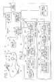
- FIGS. 4A and 4Bare a flowchart illustrating a method of the invention.
- FIG. 5is a representation of an image that would be generated with an unprocessed signal from the SWIR imager of the present invention.
- FIG. 6is a representation of an image that would be generated with an unprocessed signal from the LWIR imager of the present invention.
- FIG. 7is a representation of the processed, fused image produced on a display of the present invention.
- an enhanced vision system (EVS) 10including a multi-detector head 12 , a computer 14 , and a display 16 , all of which generally are mounted in a forward section 18 of an aircraft 20 .
- multi-detector head 12preferably includes an electric light source imager 22 for sensing infrared radiation from electric light sources, an ambient background scene imager 24 for sensing infrared radiation from a background scene, and a visible light imager 26 for sensing visible light to verify whether a human pilot should be able to view the background scene without the need for enhanced vision.
- Electric light source imager 22 and ambient background scene imager 24both produce an RS170 video signal that is monitored by computer 14 , and used to produce an image on head-up display 16 .
- Visible light imager 26is monitored by computer 14 separately from the video signals produced by video imagers 22 and 24 , and is used to select whether to display either or both of the video signals generated by imagers 22 and 24 , depending on the amount of contrast perceived by visible light imager 26 .
- Electric light source imager 22senses electromagnetic radiation with an SWIR detector 28 , preferably an uncooled InGaAs low sensitivity radiation detector, at least sensitive to electromagnetic radiation having wavelengths in the range of 1.5-microns to 1.7-microns.
- an SWIR detector 28preferably an uncooled InGaAs low sensitivity radiation detector, at least sensitive to electromagnetic radiation having wavelengths in the range of 1.5-microns to 1.7-microns.
- the focal plane array detectorincorporated in Model SU320-1.7RT-D “Indium Gallium Arsenide Near Infrared Camera” from Sensors Unlimited, Inc. in Princeton, N.J., is believed to be suitable.
- the Sensors Unlimited cameramay be modified to make it flight-worthy, and to add hardware and software for the various control and conditioning steps referred to below.
- Another uncooled detector that may work wellis an HgCtTe detector.
- the radiation sensed by SWIR detector 28is limited by a spectral filter assembly 30 , described in more detail below, to optimize the sensitivity of electric light source imager 22 to electric light sources.
- filter assembly 30may be used to limit the transmission of infrared radiation to SWIR detector 28 to only that radiation having wavelengths of greater than approximately 1.5-microns.
- Day-light transmissivity of filter assembly 30is minimal for radiation wavelengths of less than approximately 1.5-microns, which is known as the “cut-on” wavelength of filter assembly 30 . This minimizes the amount of background solar radiation sensed by SWIR detector 28 .
- filter assembly 30may allow a broader range of infrared radiation to be sensed by SWIR detector 28 , ideally ranging from 0.4-microns to 2.35-microns in wavelength.
- current detector technologydoes not require any filtering because the detectors are not sensitive to wavelengths of less than 1-micron. Accordingly, filter assembly 30 may simply remove the spectral filtration from the optical pathway of radiation incident on detector 28 during non-daylight operation.
- Standard signal conditioningmay be applied to the electronic signal 28 S generated by SWIR detector 28 to optimize the dynamic range of the electronic signal as a function of the range of electromagnetic radiation sensed. This may include adjusting integration time for the signal, and applying autogain control, autoiris control, and level control, as indicated generally at 32 .
- Various types of signal conditioningare described in the incorporated references.
- the conditioned signal 32 Sthen is processed to extract peaks or local maxima from the signal, as indicated by peak (local maxima) image extractor 34 .
- Each peak or local maximashould represent an electric light source within the field of view of electric light source imager 22 .
- the extracted maxima signal 34 S produced by peak image extractor 34then is used by an RS170 video signal generator 36 to generate a video signal 22 S in which each peak is represented by a dot of predefined size.
- the predefined sizes for the dotsmay be a function of signal intensity, spacing between peaks, and other factors, to optimize the ability of a human viewing an image produced by EVS 10 to interpret the pattern produced.
- Ambient background scene imager 24preferably includes an LWIR detector 38 .
- Detector 38may be a high-sensitivity microbolometer array 38 , sensitive to infrared radiation having wavelengths in the range of 8-microns to 14-microns.
- One LWIR detector that is believed to work wellis a Boeing Model U3000A microbolometer detector.
- detector 38might also be an MWIR detector, sensitive to infrared radiation having wavelengths in the range of 3-microns to 5-microns.
- an LWIR detectoris preferred, because it provides better imagery of cool background scenes, and better penetration of fog or other obscurants.
- Standard signal conditioningis performed on LWIR signal 38 S, including autogain and level control, histogram projection and recursive filtering, as indicated generally at 40 .
- the conditioned signal 40 Sthen is subject to edge and contrast image enhancement, as indicated at 42 .
- image enhancementis discussed in the incorporated references.
- An output signal 24 S for imager 24is generated by an RS170 video signal generator 44 , which processes enhanced signal 42 S.
- Visible light imager 26incorporates relatively standard visible light technology, including a CCD sensor, typically sensitive to radiation having wavelengths in the range of 0.4-microns to 0.7-microns. Various filtering, image conditioning and processing may be performed on the visible light signal generated by the CCD sensor, as desired. An output signal 26 S from visible light imager 26 is directed to computer 14 for additional processing.
- computer 14performs three general functions. First, computer 14 combines video signals 22 S and 24 S generated by electric light source imager 22 and ambient background scene imager 24 , as represented by infrared image fusion 46 . Second, computer 14 controls image fusion 46 based on optional visible light imager 26 , through visible image verification as indicated generally at 48 . Third, computer 14 communicates data and control with other systems of aircraft 20 , as indicated at 50 and 52 . For much of the image processing, the Matrox Genesis vision processor hardware manufactured by Matrox Electronics Systems, Ltd., Doral, Quebec, Canada, may be used as part of computer 14 .
- Computer 14monitors the signal produced by visible light imager 26 to determine if there is sufficient contrast within the image perceived by visible light imager 26 .
- a relatively high contrast within the image represented by signal 26 Sindicates that a human viewing the same scene with the naked eye should be able to perceive details of the ambient background scene.
- computer 14may be programmed to remove the video signal 24 S (ambient background scene imager 24 ) from the fused image that is displayed on display 16 . This simplifies the image substantially, while continuing to provide a pilot with computer-generated images of electric light sources.
- Computer 14coordinates EVS 10 with other devices and systems of aircraft 20 .
- the transmission of data and control between computer 14 and network 52may be bi-directional, with any of the video signals or real-world position information generated by imagers 22 , 24 , and 26 transmitted to other systems via network 52 , and override control exercised by other systems via network 52 .
- FIG. 3a combined optical portion of electric light source imager 22 and ambient background scene imager 24 is shown in more detail.
- Thisincludes an optical lens 54 , a dichroic beam splitter 56 , and a controllable iris 58 .
- Filter assembly 30 and iris 58are interposed between beam splitter 56 and SWIR detector 28 .
- a more economical optical system, using current technology,is to provide a separate lens and optical path for each imager 22 , 24 , and then align imagers 22 and 24 so that they are mutually boresighted.
- the preferred embodiment of filter assembly 30includes a filter 60 intended for use during daylight operations.
- Filter 60limits the passage to detector 28 of infrared radiation having a wavelength of less than approximately 1.5-microns.
- a filter allowing a lower range of wavelengths to passmay be used as well, but it is believed that a filter having a cut-on wavelength of less than 1.5-microns will admit too much solar background radiation for effective sensing during daylight operations.
- Filter 60may also limit the passage to detector 28 of infrared radiation having a wavelength of greater than approximately 1.7-microns (or 2.4-microns), for the reasons discussed above.
- Filter assembly 30optionally may include a nighttime filter 60 N for use during non-daylight operation.
- Nighttime filter 60 Nmay have a cut-on wavelength of approximately 1-micron, and may have a cut-off wavelength of approximately 1.7-microns, or a broader range of 0.4-microns to 2.4-microns, in part depending on the sensitivity of detector 28 .
- a filter control assembly 62may be used to control which of the filters, if any, is interposed between lens 54 and SWIR detector 28 . This control may be based on any of the radiation sensed by imagers 22 , 24 , or 26 , or based on other sensors or pilot control, as desired.
- Various alternative embodiments to filter assembly 30may develop as filter technology improves.
- FIGS. 4A and 4Bcollectively, a method of the present invention is represented in a flowchart. Some of the results of the described steps are related to the above discussion by referring to the components or signals labeled in FIG. 2 . However, it is to be understood that the method may be accomplished using various hardware and software configurations, with different signal processing, so the identification of components and signals is for illustrative purposes only, and is not to limit the scope of the invention.
- the preferred methodincludes imaging electric light sources, at 100 , imaging an ambient background scene, at 102 , and imaging a visible light view, at 104 .
- Image signals 22 S (light source), 24 S (background) and 26 S (visible light)are produced by the imaging steps 100 , 102 , and 104 , respectively, and then are processed by fusing light source image signal 22 S with background image signal 24 S, represented generally at 106 , based on image signal 26 S and control and data from other systems on aircraft 20 . This is followed by displaying the fused image signal 46 S, if desired, at 108 .
- Imaging electric light sources 100may include filtering electromagnetic radiation, at 110 , using spectral filter assembly 30 , to limit the passage to SWIR detector 28 of infrared radiation. Imaging step 100 also may include sensing the filtered radiation with SWIR detector 28 , at 112 , and conditioning the signal 28 S generated by SWIR detector 28 , using autogain, autoiris, and level control 32 , at 114 , to create a conditioned sensed electric light source signal 32 S.
- a graphic representation of a video image generated with conditioned electric light source signal 32 Sis shown in FIG. 5 .
- Conditioned signal 32 Stherefore requires additional processing, as shown in FIG. 4A, including identifying local image brightness maxima, at 116 , resulting in identified maxima signal 34 S.
- the identified maxima signalmay be transmitted directly to the step of fusing imager signals, 106 , or to other systems, as represented by dashed line 34 S.
- intelligent processing of identified maxima signal 34 Sincludes comparing identified maxima to a target database to identify a recognizable pattern, at 118 , and creating an artificial image signal representative of the recognizable pattern at 120 .
- the artificial image signalis fitted to the identified maxima, so that a complete image pattern is displayable, even when the radiation sources are obscured, intermittently or partially.
- Sensing LWIR radiation, or MWIR radiationis shown at 122 , to produce a raw background image signal 38 S, the display of which is represented in FIG. 6 .
- Conditioning raw background image signal, at 124is performed using conventional autogain control, recursive filters, and image enhancement, to create conditioned background image signal 40 S.
- imaging step 102may include identifying and enhancing local image features through edge definition procedures or other object identification procedures, at 126 , to create signal 42 S, and comparing the identified features to a database of target features to determine if the sensed features are recognizable, at 128 .
- Creating an enhanced image signal, at 130simply may be the mapping of signal 42 S, including any defined edges, to an image signal. It may also involve adding computer-generated sharpening to highlight any defined edges. In even more advanced forms, it may involve calculating an image based on available navigational data and recognizable target features, and generating an image in proper perspective that is fit to the recognizable features in the sensed image to provide a more complete image than is sensed by sensor head 12 . If desired, a completely synthetic, calculated image representing the background could be generated.
- results of comparing steps 118 and 128may be used to calculate a real-world location of aircraft 20 to supplement the navigational data referred to above.
- This location datamay be used by EVS 10 , and by other systems of aircraft 20 , as shown at steps 132 and 134 .
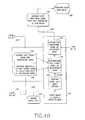
- fusing step 106 shown in FIG. 4Bincludes superimposing, at 136 , the light source signal from light source imaging step 100 , on the background signal from background imaging step 102 , when there is insufficient contrast found in the signal from the step of imaging visible light, 104 .
- Thisis followed by superimposing a navigational signal to show additional data helpful to piloting aircraft 20 , such as HUD stroke guidance symbols and other symbology, at 138 .
- fusing step 106includes only superimposing a navigational signal on the signal from imaging light sources step 100 , at 138 . Referring to FIG. 7, dots 64 and features 66 are shown, along with navigational data 68 .
- Atmospheric visibility for a human vieweris determined by verifying visible light image contrast, at 140 . If there is sufficient contrast found in visible light imaging, then it is assumed that a pilot can observe the ambient background scene without the need for enhanced vision. By removing imaging of the background scene from the resulting display, but maintaining a computer-generated image of identified light sources, useful data may be provided, without unneeded clutter. When contrast in the visible light imaging is reduced, computer-generated images of the background scene automatically are displayed again, so that a pilot may see a continuous visual image, real or generated, of the runway and background terrain, regardless of intermittent fog or other obscurant.
- the methodfurther includes aligning, at 142 , the signal generated by light source imaging 100 with the signal generated by background imaging 102 , so that relevant portions of each image correspond to one another.
- Aligning step 142may be accomplished simply by maintaining proper mechanical alignment between SWIR detector 28 and LWIR detector 38 , particularly when a single lens 54 and a dichroic beam splitter 56 are used in connection with detectors 28 and 38 .
- Readability of the resulting imageis improved, at 144 , by adjusting brightness of signals 22 S and 24 S so that the displayed brightness generated by signal 22 S is greater than the displayed brightness generated by any portion of signal 24 S.
- the methodmay include aligning the displayed fused video image with pilot perspective of the real world, at 146 , perceived through the windshield of aircraft 20 . This may be accomplished either by moving head-up display relative to a pilot, or shifting the fused video image on head-up display 16 , electronically.
- the optional steps of comparing identified point-source patterns or features to a target database, at 118 and 128require creating and maintaining a database of target patterns and features, as indicated in FIG. 4A at 148 and 150 , respectively.
- the created databasesshould include information on the global location of the target patterns and features, so that relevant portions of the database may be identified based on GPS and other navigational information from other systems of aircraft 20 .
Landscapes
- Engineering & Computer Science (AREA)
- Physics & Mathematics (AREA)
- General Physics & Mathematics (AREA)
- Aviation & Aerospace Engineering (AREA)
- Remote Sensing (AREA)
- Radar, Positioning & Navigation (AREA)
- Theoretical Computer Science (AREA)
- Signal Processing (AREA)
- Multimedia (AREA)
- Automation & Control Theory (AREA)
- Closed-Circuit Television Systems (AREA)
- Image Processing (AREA)
- Radiation Pyrometers (AREA)
- Transforming Light Signals Into Electric Signals (AREA)
Abstract
Description
Claims (58)
Priority Applications (4)
| Application Number | Priority Date | Filing Date | Title |
|---|---|---|---|
| US10/123,539US6806469B2 (en) | 1999-03-05 | 2002-04-15 | Enhanced vision system sensitive to infrared radiation |
| US10/968,858US7102130B2 (en) | 1999-03-05 | 2004-10-18 | Enhanced vision system sensitive to infrared radiation |
| US11/514,697US7655908B2 (en) | 1999-03-05 | 2006-09-01 | Enhanced vision system sensitive to infrared radiation |
| US12/698,898US20100207026A1 (en) | 1999-03-05 | 2010-02-02 | Enhanced vision system sensitive to infrared radiation |
Applications Claiming Priority (3)
| Application Number | Priority Date | Filing Date | Title |
|---|---|---|---|
| US09/263,598US6232602B1 (en) | 1999-03-05 | 1999-03-05 | Enhanced vision system sensitive to infrared radiation |
| US09/855,398US6373055B1 (en) | 1999-03-05 | 2001-05-14 | Enhanced vision system sensitive to infrared radiation |
| US10/123,539US6806469B2 (en) | 1999-03-05 | 2002-04-15 | Enhanced vision system sensitive to infrared radiation |
Related Parent Applications (1)
| Application Number | Title | Priority Date | Filing Date |
|---|---|---|---|
| US09/855,398ContinuationUS6373055B1 (en) | 1999-03-05 | 2001-05-14 | Enhanced vision system sensitive to infrared radiation |
Related Child Applications (1)
| Application Number | Title | Priority Date | Filing Date |
|---|---|---|---|
| US10/968,858ContinuationUS7102130B2 (en) | 1999-03-05 | 2004-10-18 | Enhanced vision system sensitive to infrared radiation |
Publications (2)
| Publication Number | Publication Date |
|---|---|
| US20020185600A1 US20020185600A1 (en) | 2002-12-12 |
| US6806469B2true US6806469B2 (en) | 2004-10-19 |
Family
ID=23002456
Family Applications (6)
| Application Number | Title | Priority Date | Filing Date |
|---|---|---|---|
| US09/263,598Expired - LifetimeUS6232602B1 (en) | 1999-03-05 | 1999-03-05 | Enhanced vision system sensitive to infrared radiation |
| US09/855,398Expired - LifetimeUS6373055B1 (en) | 1999-03-05 | 2001-05-14 | Enhanced vision system sensitive to infrared radiation |
| US10/123,539Expired - LifetimeUS6806469B2 (en) | 1999-03-05 | 2002-04-15 | Enhanced vision system sensitive to infrared radiation |
| US10/968,858Expired - LifetimeUS7102130B2 (en) | 1999-03-05 | 2004-10-18 | Enhanced vision system sensitive to infrared radiation |
| US11/514,697Expired - Fee RelatedUS7655908B2 (en) | 1999-03-05 | 2006-09-01 | Enhanced vision system sensitive to infrared radiation |
| US12/698,898AbandonedUS20100207026A1 (en) | 1999-03-05 | 2010-02-02 | Enhanced vision system sensitive to infrared radiation |
Family Applications Before (2)
| Application Number | Title | Priority Date | Filing Date |
|---|---|---|---|
| US09/263,598Expired - LifetimeUS6232602B1 (en) | 1999-03-05 | 1999-03-05 | Enhanced vision system sensitive to infrared radiation |
| US09/855,398Expired - LifetimeUS6373055B1 (en) | 1999-03-05 | 2001-05-14 | Enhanced vision system sensitive to infrared radiation |
Family Applications After (3)
| Application Number | Title | Priority Date | Filing Date |
|---|---|---|---|
| US10/968,858Expired - LifetimeUS7102130B2 (en) | 1999-03-05 | 2004-10-18 | Enhanced vision system sensitive to infrared radiation |
| US11/514,697Expired - Fee RelatedUS7655908B2 (en) | 1999-03-05 | 2006-09-01 | Enhanced vision system sensitive to infrared radiation |
| US12/698,898AbandonedUS20100207026A1 (en) | 1999-03-05 | 2010-02-02 | Enhanced vision system sensitive to infrared radiation |
Country Status (3)
| Country | Link |
|---|---|
| US (6) | US6232602B1 (en) |
| AU (1) | AU5721800A (en) |
| WO (1) | WO2000054217A2 (en) |
Cited By (23)
| Publication number | Priority date | Publication date | Assignee | Title |
|---|---|---|---|---|
| US20020054223A1 (en)* | 2000-09-13 | 2002-05-09 | Spriggs Timothy John | Camera systems |
| US20050161603A1 (en)* | 1999-03-05 | 2005-07-28 | Kerr Jones R. | Enhanced vision system sensitive to infrared radiation |
| US20060231913A1 (en)* | 2005-04-13 | 2006-10-19 | Clifton Labs, Inc. | Method for determining wavelengths of light incident on a stacked photodetector structure |
| US20060249679A1 (en)* | 2004-12-03 | 2006-11-09 | Johnson Kirk R | Visible light and ir combined image camera |
| US7196329B1 (en)* | 2004-06-17 | 2007-03-27 | Rockwell Collins, Inc. | Head-down enhanced vision system |
| WO2007095282A2 (en) | 2006-02-13 | 2007-08-23 | Max-Viz, Inc. | System for and method of synchronous acquisition of pulsed source light in performance of monitoring aircraft flight operation |
| US7282691B2 (en) | 2005-04-13 | 2007-10-16 | Clifton Labs, Inc. | Method for determining wavelengths of light incident on a photodetector |
| US7307793B2 (en) | 2004-07-02 | 2007-12-11 | Insight Technology, Inc. | Fusion night vision system |
| US7355179B1 (en) | 2005-07-30 | 2008-04-08 | Rockwell Collins, Inc. | Scene imaging system integrity monitor and method thereof |
| US20080099678A1 (en)* | 2004-12-03 | 2008-05-01 | Johnson Kirk R | Camera with visible light and infrared image blending |
| US20090002475A1 (en)* | 2007-06-27 | 2009-01-01 | General Instrument Corporation | Apparatus and System for Improving Image Quality |
| US20090050806A1 (en)* | 2004-12-03 | 2009-02-26 | Fluke Corporation | Visible light and ir combined image camera with a laser pointer |
| US20090079854A1 (en)* | 2006-01-29 | 2009-03-26 | Rafael- Armament Development Authority Ltd. | Non-uniformity correction of images generated by focal plane arrays of photodetectors |
| US20090196457A1 (en)* | 2008-01-31 | 2009-08-06 | Gregory Zuro | Video image processing and fusion |
| US7605774B1 (en)* | 2004-07-02 | 2009-10-20 | Rockwell Collins, Inc. | Enhanced vision system (EVS) processing window tied to flight path |
| US20100125412A1 (en)* | 2008-11-14 | 2010-05-20 | Honeywell International Inc. | Display systems with enhanced symbology |
| EP2378460A1 (en) | 2010-04-16 | 2011-10-19 | Thales | Device for assisting the taxing process of an airplane |
| US8635009B2 (en) | 2011-06-10 | 2014-01-21 | Thales | Method for creation of a taxiing route over an airport area and associated device |
| US9347794B1 (en) | 2012-09-21 | 2016-05-24 | Rockwell Collins, Inc. | Image data combining systems and methods of multiple vision systems |
| US20160234489A1 (en)* | 2014-06-23 | 2016-08-11 | Unlimited Optics Corp. | Method for measuring performance parameters and detecting bad pixels of an infrared focal plane array module |
| US9723229B2 (en) | 2010-08-27 | 2017-08-01 | Milwaukee Electric Tool Corporation | Thermal detection systems, methods, and devices |
| US9883084B2 (en) | 2011-03-15 | 2018-01-30 | Milwaukee Electric Tool Corporation | Thermal imager |
| US10794769B2 (en) | 2012-08-02 | 2020-10-06 | Milwaukee Electric Tool Corporation | Thermal detection systems, methods, and devices |
Families Citing this family (76)
| Publication number | Priority date | Publication date | Assignee | Title |
|---|---|---|---|---|
| US6255650B1 (en)* | 1998-12-11 | 2001-07-03 | Flir Systems, Inc. | Extreme temperature radiometry and imaging apparatus |
| US6815687B1 (en)* | 1999-04-16 | 2004-11-09 | The Regents Of The University Of Michigan | Method and system for high-speed, 3D imaging of optically-invisible radiation |
| US6734962B2 (en)* | 2000-10-13 | 2004-05-11 | Chemimage Corporation | Near infrared chemical imaging microscope |
| DE10035223A1 (en)* | 2000-07-20 | 2002-01-31 | Daimler Chrysler Ag | Device and method for monitoring the surroundings of an object |
| SE521820C2 (en)* | 2000-10-13 | 2003-12-09 | Saab Ab | Method and device for automatic landing |
| EP1273928A1 (en)* | 2001-07-06 | 2003-01-08 | Leica Geosystems AG | Method and device for suppressing electromagnetic background radiation in an image |
| DE10138361A1 (en)* | 2001-08-04 | 2003-02-27 | Daimler Chrysler Ag | Method for improving the visibility in vehicles |
| US6700123B2 (en)* | 2002-01-29 | 2004-03-02 | K. W. Muth Company | Object detection apparatus |
| US6759949B2 (en)* | 2002-05-23 | 2004-07-06 | Visteon Global Technologies, Inc. | Image enhancement in far infrared camera |
| WO2004034373A2 (en)* | 2002-10-09 | 2004-04-22 | Ohio University | Multi-view head-up synthetic vision display system |
| FR2846448B1 (en)* | 2002-10-29 | 2005-01-14 | Thales Sa | DEVICE FOR PROCESSING RECOGNIZING IMAGES AND SELECTING LIGHT SOURCES |
| DE10253510A1 (en)* | 2002-11-16 | 2004-05-27 | Robert Bosch Gmbh | Visibility improvement device in motor vehicle, has processing unit with arrangement for detecting road profile from acquired optical signal(s) and controlling signaling arrangement accordingly |
| US20040119822A1 (en)* | 2002-12-20 | 2004-06-24 | Custer Robert J. | Multiple camera system on single monitor display |
| US20070035625A9 (en)* | 2002-12-20 | 2007-02-15 | Hamdan Majed M | Vehicle video processing system |
| EP1588136A4 (en)* | 2003-01-31 | 2006-03-22 | Mikron Infrared Inc Formerly K | THERMOGRAPHIC APPARATUS |
| US7146084B2 (en)* | 2003-06-16 | 2006-12-05 | Cmc Electronics, Inc. | Fiber optic light source for display devices |
| US20050093975A1 (en)* | 2003-10-30 | 2005-05-05 | Hamdan Majed M. | Adaptation of vision systems for commerical vehicles |
| EP1738413A4 (en)* | 2004-03-23 | 2008-05-28 | Bae Systems Information | MULTI-SPECTRAL NON-COOLED MICROBOLOMETER TYPE DETECTORS |
| US20050232512A1 (en)* | 2004-04-20 | 2005-10-20 | Max-Viz, Inc. | Neural net based processor for synthetic vision fusion |
| US20050265584A1 (en)* | 2004-05-28 | 2005-12-01 | Dobson Stephen E | Imaging systems and methods |
| US7617022B1 (en) | 2004-07-01 | 2009-11-10 | Rockwell Collins, Inc. | Dual wavelength enhanced vision system optimized for visual landing light alignment |
| US20060034535A1 (en)* | 2004-08-10 | 2006-02-16 | Koch Roger D | Method and apparatus for enhancing visibility to a machine operator |
| US20060125658A1 (en)* | 2004-12-10 | 2006-06-15 | Deutsches Zentrum For Luft-Und Raumfahrt E.V. | System for assisting navigation operation of moving objects |
| US7235768B1 (en)* | 2005-02-28 | 2007-06-26 | United States Of America As Represented By The Secretary Of The Air Force | Solid state vision enhancement device |
| US7862188B2 (en)* | 2005-07-01 | 2011-01-04 | Flir Systems, Inc. | Image detection improvement via compensatory high frequency motions of an undedicated mirror |
| US9298014B2 (en)* | 2005-07-01 | 2016-03-29 | Flir Systems, Inc. | Image stabilization system |
| US7484668B1 (en)* | 2005-10-03 | 2009-02-03 | Building Protection Systems, Inc. | Building protection system and method |
| US7528372B2 (en) | 2005-10-19 | 2009-05-05 | Csi Technology, Inc. | Apparatus and method for infrared imaging with performance algorithm |
| DE102005053899A1 (en)* | 2005-11-09 | 2007-05-10 | Vaisala Gmbh | Method for determining optimal runway firing intensity |
| US7679528B1 (en)* | 2006-07-28 | 2010-03-16 | Rockwell Collins, Inc. | Modulation of aircraft guidance lights |
| US7629582B2 (en)* | 2006-10-24 | 2009-12-08 | Raytheon Company | Dual band imager with visible or SWIR detectors combined with uncooled LWIR detectors |
| US7767963B1 (en) | 2006-12-08 | 2010-08-03 | Draeger Safety, Inc. | Thermal imaging camera internal damping system |
| WO2008086297A2 (en)* | 2007-01-08 | 2008-07-17 | Max-Viz, Inc. | Assessing runway visibility to airborne infrared vision devices |
| US8189938B2 (en)* | 2007-01-10 | 2012-05-29 | L-3 Insight Technology Incorporated | Enhanced infrared imaging system |
| CA2691375C (en)* | 2007-07-18 | 2014-05-20 | Elbit Systems Ltd. | Aircraft landing assistance |
| US9354633B1 (en) | 2008-10-31 | 2016-05-31 | Rockwell Collins, Inc. | System and method for ground navigation |
| US8917191B1 (en)* | 2011-09-22 | 2014-12-23 | Rockwell Collins, Inc. | Dual threaded system for low visibility operations |
| US9733349B1 (en) | 2007-09-06 | 2017-08-15 | Rockwell Collins, Inc. | System for and method of radar data processing for low visibility landing applications |
| US8896480B1 (en) | 2011-09-28 | 2014-11-25 | Rockwell Collins, Inc. | System for and method of displaying an image derived from weather radar data |
| US9939526B2 (en) | 2007-09-06 | 2018-04-10 | Rockwell Collins, Inc. | Display system and method using weather radar sensing |
| FR2923068B1 (en)* | 2007-10-26 | 2010-06-11 | Thales Sa | VISUALIZATION DEVICE COMPRISING AN ELECTRONIC MEANS OF GEL DISPLAY. |
| CA2721662C (en) | 2008-04-16 | 2016-06-07 | Elbit Systems Ltd. | Multispectral enhanced vision system and method for aircraft landing in inclement weather conditions |
| US8290301B2 (en) | 2009-02-06 | 2012-10-16 | Raytheon Company | Optimized imaging system for collection of high resolution imagery |
| US20140347482A1 (en)* | 2009-02-20 | 2014-11-27 | Appareo Systems, Llc | Optical image monitoring system and method for unmanned aerial vehicles |
| FR2947083B1 (en)* | 2009-06-23 | 2011-11-11 | Thales Sa | DEVICE AND METHOD FOR LANDFILLING |
| US8577183B2 (en)* | 2009-08-05 | 2013-11-05 | Raytheon Company | Resolution on demand |
| US8497914B2 (en) | 2009-08-10 | 2013-07-30 | Wisconsin Alumni Research Foundation | Vision system and method for motion adaptive integration of image frames |
| GB0921944D0 (en)* | 2009-12-16 | 2010-02-03 | St Microelectronics Ltd | Improvements in or relating to compact fluorescent lamps |
| US20110261351A1 (en)* | 2010-02-05 | 2011-10-27 | Chemimage Corporation | System and method for detecting explosives using swir and mwir hyperspectral imaging |
| US9105115B2 (en)* | 2010-03-16 | 2015-08-11 | Honeywell International Inc. | Display systems and methods for displaying enhanced vision and synthetic images |
| US8699781B1 (en) | 2010-06-14 | 2014-04-15 | Rockwell Collins, Inc. | Embedded symbology for use with scene imaging system |
| US8400330B2 (en) | 2010-09-07 | 2013-03-19 | Honeywell International Inc. | System for displaying multiple overlaid images to a pilot of an aircraft during flight |
| DE102010048022B4 (en)* | 2010-10-09 | 2013-08-14 | Testo Ag | Method for the contactless determination of the temperature of an object and corresponding thermal imaging camera |
| US8493241B2 (en) | 2010-11-30 | 2013-07-23 | Honeywell International Inc. | Systems, methods and computer readable media for displaying multiple overlaid images to a pilot of an aircraft during flight |
| US9092975B2 (en)* | 2011-02-23 | 2015-07-28 | Honeywell International Inc. | Aircraft systems and methods for displaying visual segment information |
| IL212401A0 (en)* | 2011-04-17 | 2012-01-31 | Elta Systems Ltd | A system and a method for extended swir thermal imaging |
| US8836794B2 (en) | 2011-08-15 | 2014-09-16 | The United States Of America As Represented By The Secretary Of The Army | Dual field of view multi-band optics |
| US9177204B1 (en)* | 2011-09-28 | 2015-11-03 | Rockwell Collins, Inc. | Spectrally enhanced vision system for low visibility operations |
| US8868265B2 (en) | 2011-11-30 | 2014-10-21 | Honeywell International Inc. | System and method for aligning aircraft and runway headings during takeoff roll |
| US8654149B2 (en) | 2011-12-20 | 2014-02-18 | Honeywell International Inc. | System and method for displaying enhanced vision and synthetic images |
| US8698654B2 (en) | 2011-12-28 | 2014-04-15 | Honeywell International Inc. | System and method for selecting images to be displayed |
| US9165366B2 (en) | 2012-01-19 | 2015-10-20 | Honeywell International Inc. | System and method for detecting and displaying airport approach lights |
| US9262932B1 (en) | 2013-04-05 | 2016-02-16 | Rockwell Collins, Inc. | Extended runway centerline systems and methods |
| US9734729B2 (en)* | 2013-04-11 | 2017-08-15 | Honeywell International Inc. | Methods and systems for providing taxiway stop bar information to an aircrew |
| US9139307B2 (en) | 2013-06-28 | 2015-09-22 | Honeywell International Inc. | Aircraft systems and methods for displaying runway lighting information |
| US9485439B2 (en)* | 2013-12-03 | 2016-11-01 | Sensors Unlimited, Inc. | Shortwave infrared camera with bandwidth restriction |
| US9177481B2 (en)* | 2013-12-13 | 2015-11-03 | Sikorsky Aircraft Corporation | Semantics based safe landing area detection for an unmanned vehicle |
| US10928510B1 (en) | 2014-09-10 | 2021-02-23 | Rockwell Collins, Inc. | System for and method of image processing for low visibility landing applications |
| US10336462B2 (en) | 2015-03-12 | 2019-07-02 | Vu Systems, LLC | Vehicle navigation methods, systems and computer program products |
| FR3033649B1 (en)* | 2015-03-12 | 2018-06-15 | Sagem Defense Securite | AIRPROOF FIRE DETECTION EQUIPMENT AND STEERING AID |
| US10825567B1 (en)* | 2015-08-21 | 2020-11-03 | Food2Life, LLC | Apparatus and method for informed personal well-being decision making |
| US10705201B1 (en) | 2015-08-31 | 2020-07-07 | Rockwell Collins, Inc. | Radar beam sharpening system and method |
| US10228460B1 (en) | 2016-05-26 | 2019-03-12 | Rockwell Collins, Inc. | Weather radar enabled low visibility operation system and method |
| US10353068B1 (en) | 2016-07-28 | 2019-07-16 | Rockwell Collins, Inc. | Weather radar enabled offshore operation system and method |
| EP3688635B1 (en)* | 2017-09-28 | 2022-12-07 | Hewlett-Packard Development Company, L.P. | Magnetic switch |
| US11070763B2 (en)* | 2018-06-27 | 2021-07-20 | Snap-On Incorporated | Method and system for displaying images captured by a computing device including a visible light camera and a thermal camera |
Citations (18)
| Publication number | Priority date | Publication date | Assignee | Title |
|---|---|---|---|---|
| US3665198A (en) | 1969-02-28 | 1972-05-23 | Norwegian Defence Research Est | Aircraft landing guidance system using collimated fan shaped radiation beams |
| US4086616A (en) | 1976-12-23 | 1978-04-25 | The United States Of America As Represented By The Secretary Of The Navy | All-weather multi-spectral imaging system |
| US4862164A (en) | 1988-02-09 | 1989-08-29 | The United States Of America As Represented By The Secretary Of The Army | Infrared aircraft landing system |
| US5140416A (en) | 1990-09-18 | 1992-08-18 | Texas Instruments Incorporated | System and method for fusing video imagery from multiple sources in real time |
| US5161107A (en) | 1990-10-25 | 1992-11-03 | Mestech Creation Corporation | Traffic surveillance system |
| US5440139A (en) | 1994-03-02 | 1995-08-08 | Grumman Aerospace Corporation | Circuit for optically coupling a cryobenic detector array with processing circuitry and for increasing the dynamic range of detection |
| US5534694A (en) | 1992-06-04 | 1996-07-09 | Hughes Electronics | Infrared imaging system for enhancing the perception of a scene by a vehicle operator |
| US5654890A (en) | 1994-05-31 | 1997-08-05 | Lockheed Martin | High resolution autonomous precision approach and landing system |
| US5698852A (en) | 1994-08-11 | 1997-12-16 | Nec Corporation | Titanium bolometer-type infrared detecting apparatus |
| US5699278A (en) | 1995-01-24 | 1997-12-16 | Brajovic; Vladimir M. | Focal plane processor |
| US5719567A (en) | 1995-05-30 | 1998-02-17 | Victor J. Norris, Jr. | System for enhancing navigation and surveillance in low visibility conditions |
| US5808350A (en) | 1997-01-03 | 1998-09-15 | Raytheon Company | Integrated IR, visible and NIR sensor and methods of fabricating same |
| US5811807A (en) | 1996-07-19 | 1998-09-22 | Ail Systems, Inc. | Uncooled background limited detector and method |
| US5811815A (en) | 1995-11-15 | 1998-09-22 | Lockheed-Martin Ir Imaging Systems, Inc. | Dual-band multi-level microbridge detector |
| US5818052A (en) | 1996-04-18 | 1998-10-06 | Loral Fairchild Corp. | Low light level solid state image sensor |
| US5836872A (en) | 1989-04-13 | 1998-11-17 | Vanguard Imaging, Ltd. | Digital optical visualization, enhancement, quantification, and classification of surface and subsurface features of body surfaces |
| US6009340A (en) | 1998-03-16 | 1999-12-28 | Northrop Grumman Corporation | Multimode, multispectral imaging system |
| US6373055B1 (en)* | 1999-03-05 | 2002-04-16 | Flir Systems, Inc. | Enhanced vision system sensitive to infrared radiation |
Family Cites Families (3)
| Publication number | Priority date | Publication date | Assignee | Title |
|---|---|---|---|---|
| US4881270A (en)* | 1983-10-28 | 1989-11-14 | The United States Of America As Represented By The Secretary Of The Navy | Automatic classification of images |
| WO1999036904A1 (en)* | 1998-01-16 | 1999-07-22 | Thresholds Unlimited, Inc. | Head up display and vision system |
| US6255650B1 (en)* | 1998-12-11 | 2001-07-03 | Flir Systems, Inc. | Extreme temperature radiometry and imaging apparatus |
- 1999
- 1999-03-05USUS09/263,598patent/US6232602B1/ennot_activeExpired - Lifetime
- 2000
- 2000-03-01WOPCT/US2000/005455patent/WO2000054217A2/enactiveApplication Filing
- 2000-03-01AUAU57218/00Apatent/AU5721800A/ennot_activeAbandoned
- 2001
- 2001-05-14USUS09/855,398patent/US6373055B1/ennot_activeExpired - Lifetime
- 2002
- 2002-04-15USUS10/123,539patent/US6806469B2/ennot_activeExpired - Lifetime
- 2004
- 2004-10-18USUS10/968,858patent/US7102130B2/ennot_activeExpired - Lifetime
- 2006
- 2006-09-01USUS11/514,697patent/US7655908B2/ennot_activeExpired - Fee Related
- 2010
- 2010-02-02USUS12/698,898patent/US20100207026A1/ennot_activeAbandoned
Patent Citations (18)
| Publication number | Priority date | Publication date | Assignee | Title |
|---|---|---|---|---|
| US3665198A (en) | 1969-02-28 | 1972-05-23 | Norwegian Defence Research Est | Aircraft landing guidance system using collimated fan shaped radiation beams |
| US4086616A (en) | 1976-12-23 | 1978-04-25 | The United States Of America As Represented By The Secretary Of The Navy | All-weather multi-spectral imaging system |
| US4862164A (en) | 1988-02-09 | 1989-08-29 | The United States Of America As Represented By The Secretary Of The Army | Infrared aircraft landing system |
| US5836872A (en) | 1989-04-13 | 1998-11-17 | Vanguard Imaging, Ltd. | Digital optical visualization, enhancement, quantification, and classification of surface and subsurface features of body surfaces |
| US5140416A (en) | 1990-09-18 | 1992-08-18 | Texas Instruments Incorporated | System and method for fusing video imagery from multiple sources in real time |
| US5161107A (en) | 1990-10-25 | 1992-11-03 | Mestech Creation Corporation | Traffic surveillance system |
| US5534694A (en) | 1992-06-04 | 1996-07-09 | Hughes Electronics | Infrared imaging system for enhancing the perception of a scene by a vehicle operator |
| US5440139A (en) | 1994-03-02 | 1995-08-08 | Grumman Aerospace Corporation | Circuit for optically coupling a cryobenic detector array with processing circuitry and for increasing the dynamic range of detection |
| US5654890A (en) | 1994-05-31 | 1997-08-05 | Lockheed Martin | High resolution autonomous precision approach and landing system |
| US5698852A (en) | 1994-08-11 | 1997-12-16 | Nec Corporation | Titanium bolometer-type infrared detecting apparatus |
| US5699278A (en) | 1995-01-24 | 1997-12-16 | Brajovic; Vladimir M. | Focal plane processor |
| US5719567A (en) | 1995-05-30 | 1998-02-17 | Victor J. Norris, Jr. | System for enhancing navigation and surveillance in low visibility conditions |
| US5811815A (en) | 1995-11-15 | 1998-09-22 | Lockheed-Martin Ir Imaging Systems, Inc. | Dual-band multi-level microbridge detector |
| US5818052A (en) | 1996-04-18 | 1998-10-06 | Loral Fairchild Corp. | Low light level solid state image sensor |
| US5811807A (en) | 1996-07-19 | 1998-09-22 | Ail Systems, Inc. | Uncooled background limited detector and method |
| US5808350A (en) | 1997-01-03 | 1998-09-15 | Raytheon Company | Integrated IR, visible and NIR sensor and methods of fabricating same |
| US6009340A (en) | 1998-03-16 | 1999-12-28 | Northrop Grumman Corporation | Multimode, multispectral imaging system |
| US6373055B1 (en)* | 1999-03-05 | 2002-04-16 | Flir Systems, Inc. | Enhanced vision system sensitive to infrared radiation |
Non-Patent Citations (9)
| Title |
|---|
| David C. Burnham et al., United States Experience Using Forward Scattermeters for Runway Visual Range, U.S. Department of Transportation, Federal Aviation Administration, Document No. DOT/FAA/AND-97/1; DOT-VNTSC-FAA-97-1, Mar. 1997. |
| FLIR Systems, Inc.-FSI Corporation Information / Media Room, FSI internet page, Jan. 11, 1999. |
| FLIR Systems, Inc.—FSI Corporation Information / Media Room, FSI internet page, Jan. 11, 1999. |
| FLIR Systems, Inc.-Resource Center / Theory of Thermography, FSI internet page, Jan. 11, 1999, pp. 1-7. |
| FLIR Systems, Inc.—Resource Center / Theory of Thermography, FSI internet page, Jan. 11, 1999, pp. 1-7. |
| Matrox Imaging Products-Matrox Genesis, internet page, Mar. 4, 1999, pp. 1-17. |
| Matrox Imaging Products—Matrox Genesis, internet page, Mar. 4, 1999, pp. 1-17. |
| Michael Johnson and Clark Rogers, "Photo-realistic scene presentation: 'virtual video camera'", SPIE, vol. 2220, pp. 294-302, Mar. 1994. |
| Michael Johnson and Clark Rogers, "Photo-realistic scene presentation: ‘virtual video camera’", SPIE, vol. 2220, pp. 294-302, Mar. 1994. |
Cited By (48)
| Publication number | Priority date | Publication date | Assignee | Title |
|---|---|---|---|---|
| US20050161603A1 (en)* | 1999-03-05 | 2005-07-28 | Kerr Jones R. | Enhanced vision system sensitive to infrared radiation |
| US7102130B2 (en) | 1999-03-05 | 2006-09-05 | Flir Systems, Inc. | Enhanced vision system sensitive to infrared radiation |
| US7655908B2 (en) | 1999-03-05 | 2010-02-02 | Flir Systems, Inc. | Enhanced vision system sensitive to infrared radiation |
| US20070075244A1 (en)* | 1999-03-05 | 2007-04-05 | Kerr Jones R | Enhanced vision system sensitive to infrared radiation |
| US20100207026A1 (en)* | 1999-03-05 | 2010-08-19 | Janes Richard Kerr | Enhanced vision system sensitive to infrared radiation |
| US20020054223A1 (en)* | 2000-09-13 | 2002-05-09 | Spriggs Timothy John | Camera systems |
| US7196329B1 (en)* | 2004-06-17 | 2007-03-27 | Rockwell Collins, Inc. | Head-down enhanced vision system |
| US7307793B2 (en) | 2004-07-02 | 2007-12-11 | Insight Technology, Inc. | Fusion night vision system |
| US7605774B1 (en)* | 2004-07-02 | 2009-10-20 | Rockwell Collins, Inc. | Enhanced vision system (EVS) processing window tied to flight path |
| US20080099678A1 (en)* | 2004-12-03 | 2008-05-01 | Johnson Kirk R | Camera with visible light and infrared image blending |
| US7535002B2 (en) | 2004-12-03 | 2009-05-19 | Fluke Corporation | Camera with visible light and infrared image blending |
| US7994480B2 (en) | 2004-12-03 | 2011-08-09 | Fluke Corporation | Visible light and IR combined image camera |
| US11032492B2 (en) | 2004-12-03 | 2021-06-08 | Fluke Corporation | Visible light and IR combined image camera |
| US9635282B2 (en) | 2004-12-03 | 2017-04-25 | Fluke Corporation | Visible light and IR combined image camera |
| US8531562B2 (en) | 2004-12-03 | 2013-09-10 | Fluke Corporation | Visible light and IR combined image camera with a laser pointer |
| US8466422B2 (en) | 2004-12-03 | 2013-06-18 | Fluke Corporation | Visible light and IR combined image camera |
| US20090050806A1 (en)* | 2004-12-03 | 2009-02-26 | Fluke Corporation | Visible light and ir combined image camera with a laser pointer |
| US20060249679A1 (en)* | 2004-12-03 | 2006-11-09 | Johnson Kirk R | Visible light and ir combined image camera |
| US20090302219A1 (en)* | 2004-12-03 | 2009-12-10 | Fluke Corporation | Visible light and ir combined image camera |
| US7538326B2 (en) | 2004-12-03 | 2009-05-26 | Fluke Corporation | Visible light and IR combined image camera with a laser pointer |
| US20060289772A1 (en)* | 2004-12-03 | 2006-12-28 | Johnson Kirk R | Visible light and IR combined image camera with a laser pointer |
| US7282691B2 (en) | 2005-04-13 | 2007-10-16 | Clifton Labs, Inc. | Method for determining wavelengths of light incident on a photodetector |
| US20060231913A1 (en)* | 2005-04-13 | 2006-10-19 | Clifton Labs, Inc. | Method for determining wavelengths of light incident on a stacked photodetector structure |
| US7355179B1 (en) | 2005-07-30 | 2008-04-08 | Rockwell Collins, Inc. | Scene imaging system integrity monitor and method thereof |
| US8319862B2 (en)* | 2006-01-29 | 2012-11-27 | Rafael Advanced Defense Systems Ltd. | Non-uniformity correction of images generated by focal plane arrays of photodetectors |
| US20090079854A1 (en)* | 2006-01-29 | 2009-03-26 | Rafael- Armament Development Authority Ltd. | Non-uniformity correction of images generated by focal plane arrays of photodetectors |
| US7705879B2 (en) | 2006-02-13 | 2010-04-27 | Max-Viz, Inc. | System for and method of synchronous acquisition of pulsed source light in performance of monitoring aircraft flight operation |
| USRE45452E1 (en) | 2006-02-13 | 2015-04-07 | Max-Viz, Inc. | System for and method of synchronous acquisition of pulsed source light in performance of monitoring aircraft flight operation |
| WO2007095282A2 (en) | 2006-02-13 | 2007-08-23 | Max-Viz, Inc. | System for and method of synchronous acquisition of pulsed source light in performance of monitoring aircraft flight operation |
| US20090009596A1 (en)* | 2006-02-13 | 2009-01-08 | Max-Viz, Inc | System for and method of synchronous acquisition of pulsed source light in performance of monitoring aircraft flight operation |
| USRE44604E1 (en) | 2006-02-13 | 2013-11-19 | Max-Viz, Inc. | System for and method of synchronous acquisition of pulsed source light in performance of monitoring aircraft flight operation |
| WO2007095282A3 (en)* | 2006-02-13 | 2008-10-30 | Max Viz Inc | System for and method of synchronous acquisition of pulsed source light in performance of monitoring aircraft flight operation |
| US8368741B2 (en) | 2007-06-27 | 2013-02-05 | General Instrument Corporation | Apparatus and system for improving image quality |
| US20090002475A1 (en)* | 2007-06-27 | 2009-01-01 | General Instrument Corporation | Apparatus and System for Improving Image Quality |
| US8144927B2 (en) | 2008-01-31 | 2012-03-27 | Max-Viz, Inc. | Video image processing and fusion |
| US20090196457A1 (en)* | 2008-01-31 | 2009-08-06 | Gregory Zuro | Video image processing and fusion |
| US8065082B2 (en) | 2008-11-14 | 2011-11-22 | Honeywell International Inc. | Display systems with enhanced symbology |
| US20100125412A1 (en)* | 2008-11-14 | 2010-05-20 | Honeywell International Inc. | Display systems with enhanced symbology |
| US8670921B2 (en) | 2010-04-16 | 2014-03-11 | Thales | Onboard assistance device for aiding the following of an airport route by an aircraft |
| EP2378460A1 (en) | 2010-04-16 | 2011-10-19 | Thales | Device for assisting the taxing process of an airplane |
| US9723229B2 (en) | 2010-08-27 | 2017-08-01 | Milwaukee Electric Tool Corporation | Thermal detection systems, methods, and devices |
| US9883084B2 (en) | 2011-03-15 | 2018-01-30 | Milwaukee Electric Tool Corporation | Thermal imager |
| US8635009B2 (en) | 2011-06-10 | 2014-01-21 | Thales | Method for creation of a taxiing route over an airport area and associated device |
| US10794769B2 (en) | 2012-08-02 | 2020-10-06 | Milwaukee Electric Tool Corporation | Thermal detection systems, methods, and devices |
| US11378460B2 (en) | 2012-08-02 | 2022-07-05 | Milwaukee Electric Tool Corporation | Thermal detection systems, methods, and devices |
| US9347794B1 (en) | 2012-09-21 | 2016-05-24 | Rockwell Collins, Inc. | Image data combining systems and methods of multiple vision systems |
| US20160234489A1 (en)* | 2014-06-23 | 2016-08-11 | Unlimited Optics Corp. | Method for measuring performance parameters and detecting bad pixels of an infrared focal plane array module |
| US9883178B2 (en)* | 2014-06-23 | 2018-01-30 | Unlimited Optics Corp. | Method for measuring performance parameters and detecting bad pixels of an infrared focal plane array module |
Also Published As
| Publication number | Publication date |
|---|---|
| AU5721800A (en) | 2000-09-28 |
| US7655908B2 (en) | 2010-02-02 |
| US20070075244A1 (en) | 2007-04-05 |
| US20100207026A1 (en) | 2010-08-19 |
| WO2000054217A3 (en) | 2001-04-26 |
| US20050161603A1 (en) | 2005-07-28 |
| US7102130B2 (en) | 2006-09-05 |
| US6232602B1 (en) | 2001-05-15 |
| US20020185600A1 (en) | 2002-12-12 |
| US6373055B1 (en) | 2002-04-16 |
| WO2000054217A2 (en) | 2000-09-14 |
Similar Documents
| Publication | Publication Date | Title |
|---|---|---|
| US6806469B2 (en) | Enhanced vision system sensitive to infrared radiation | |
| EP3268798B1 (en) | Dual-mode illuminator for imaging under different lighting conditions | |
| US10495884B2 (en) | Visual perception enhancement of displayed color symbology | |
| CA2721662C (en) | Multispectral enhanced vision system and method for aircraft landing in inclement weather conditions | |
| US10564267B2 (en) | High dynamic range imaging of environment with a high intensity reflecting/transmitting source | |
| US10126554B2 (en) | Visual perception enhancement of displayed color symbology | |
| US6379009B1 (en) | Conjugate optics projection display with image enhancement | |
| EP1989681B1 (en) | System for and method of synchronous acquisition of pulsed source light in performance of monitoring aircraft flight operation | |
| US20150288948A1 (en) | System and method for night vision object detection and driver assistance | |
| EP1160541A1 (en) | Integrated vision system | |
| US9726486B1 (en) | System and method for merging enhanced vision data with a synthetic vision data | |
| US8373590B1 (en) | Method and a system for processing and displaying images of the surroundings of an aircraft | |
| EP3350986B1 (en) | Systems and methods for detecting light sources | |
| JPH07323899A (en) | Device for replacing artificial image indicated to aircraft pilot with corresponding actual image | |
| CA3233479A1 (en) | Method for detecting obstacles | |
| US10587824B2 (en) | Imaging systems with pulse detection for search and rescue |
Legal Events
| Date | Code | Title | Description |
|---|---|---|---|
| AS | Assignment | Owner name:FLIR SYSTEMS, INC., OREGON Free format text:ASSIGNMENT OF ASSIGNORS INTEREST;ASSIGNOR:KERR, J. RICHARD;REEL/FRAME:014832/0116 Effective date:19990304 | |
| STCF | Information on status: patent grant | Free format text:PATENTED CASE | |
| AS | Assignment | Owner name:BANK OF AMERICA, N.A., AS ADMINISTRATIVE AGENT,WAS Free format text:NOTICE OF GRANT OF SECURITY INTEREST;ASSIGNOR:FLIR SYSTEMS, INC.;REEL/FRAME:018420/0494 Effective date:20061006 Owner name:BANK OF AMERICA, N.A., AS ADMINISTRATIVE AGENT, WA Free format text:NOTICE OF GRANT OF SECURITY INTEREST;ASSIGNOR:FLIR SYSTEMS, INC.;REEL/FRAME:018420/0494 Effective date:20061006 | |
| REMI | Maintenance fee reminder mailed | ||
| FPAY | Fee payment | Year of fee payment:4 | |
| SULP | Surcharge for late payment | ||
| AS | Assignment | Owner name:FLIR SYSTEMS, INC., OREGON Free format text:TERMINATION OF SECURITY INTEREST IN PATENTS RECORDED AT REEL/FRAME 18420/494;ASSIGNOR:BANK OF AMERICA, N.A., AS ADMINISTRATIVE AGENT;REEL/FRAME:025775/0972 Effective date:20110208 | |
| FPAY | Fee payment | Year of fee payment:8 | |
| REMI | Maintenance fee reminder mailed | ||
| FPAY | Fee payment | Year of fee payment:12 | |
| SULP | Surcharge for late payment | Year of fee payment:11 | |
| AS | Assignment | Owner name:TELEDYNE FLIR, LLC, CALIFORNIA Free format text:MERGER AND CHANGE OF NAME;ASSIGNORS:FLIR SYSTEMS, INC.;FIREWORK MERGER SUB II, LLC;REEL/FRAME:058250/0300 Effective date:20210514 |