US6805694B2 - Laser system for corneal grafting - Google Patents
Laser system for corneal graftingDownload PDFInfo
- Publication number
- US6805694B2 US6805694B2US10/141,902US14190202AUS6805694B2US 6805694 B2US6805694 B2US 6805694B2US 14190202 AUS14190202 AUS 14190202AUS 6805694 B2US6805694 B2US 6805694B2
- Authority
- US
- United States
- Prior art keywords
- cornea
- laser system
- laser
- foci
- path
- Prior art date
- Legal status (The legal status is an assumption and is not a legal conclusion. Google has not performed a legal analysis and makes no representation as to the accuracy of the status listed.)
- Expired - Lifetime, expires
Links
Images

Classifications
- A—HUMAN NECESSITIES
- A61—MEDICAL OR VETERINARY SCIENCE; HYGIENE
- A61F—FILTERS IMPLANTABLE INTO BLOOD VESSELS; PROSTHESES; DEVICES PROVIDING PATENCY TO, OR PREVENTING COLLAPSING OF, TUBULAR STRUCTURES OF THE BODY, e.g. STENTS; ORTHOPAEDIC, NURSING OR CONTRACEPTIVE DEVICES; FOMENTATION; TREATMENT OR PROTECTION OF EYES OR EARS; BANDAGES, DRESSINGS OR ABSORBENT PADS; FIRST-AID KITS
- A61F9/00—Methods or devices for treatment of the eyes; Devices for putting in contact-lenses; Devices to correct squinting; Apparatus to guide the blind; Protective devices for the eyes, carried on the body or in the hand
- A61F9/007—Methods or devices for eye surgery
- A61F9/008—Methods or devices for eye surgery using laser
- A61F9/00825—Methods or devices for eye surgery using laser for photodisruption
- A61F9/00831—Transplantation
- A—HUMAN NECESSITIES
- A61—MEDICAL OR VETERINARY SCIENCE; HYGIENE
- A61F—FILTERS IMPLANTABLE INTO BLOOD VESSELS; PROSTHESES; DEVICES PROVIDING PATENCY TO, OR PREVENTING COLLAPSING OF, TUBULAR STRUCTURES OF THE BODY, e.g. STENTS; ORTHOPAEDIC, NURSING OR CONTRACEPTIVE DEVICES; FOMENTATION; TREATMENT OR PROTECTION OF EYES OR EARS; BANDAGES, DRESSINGS OR ABSORBENT PADS; FIRST-AID KITS
- A61F9/00—Methods or devices for treatment of the eyes; Devices for putting in contact-lenses; Devices to correct squinting; Apparatus to guide the blind; Protective devices for the eyes, carried on the body or in the hand
- A61F9/007—Methods or devices for eye surgery
- A61F9/008—Methods or devices for eye surgery using laser
- A61F2009/00861—Methods or devices for eye surgery using laser adapted for treatment at a particular location
- A61F2009/00872—Cornea
- A—HUMAN NECESSITIES
- A61—MEDICAL OR VETERINARY SCIENCE; HYGIENE
- A61F—FILTERS IMPLANTABLE INTO BLOOD VESSELS; PROSTHESES; DEVICES PROVIDING PATENCY TO, OR PREVENTING COLLAPSING OF, TUBULAR STRUCTURES OF THE BODY, e.g. STENTS; ORTHOPAEDIC, NURSING OR CONTRACEPTIVE DEVICES; FOMENTATION; TREATMENT OR PROTECTION OF EYES OR EARS; BANDAGES, DRESSINGS OR ABSORBENT PADS; FIRST-AID KITS
- A61F9/00—Methods or devices for treatment of the eyes; Devices for putting in contact-lenses; Devices to correct squinting; Apparatus to guide the blind; Protective devices for the eyes, carried on the body or in the hand
- A61F9/007—Methods or devices for eye surgery
- A61F9/013—Instruments for compensation of ocular refraction ; Instruments for use in cornea removal, for reshaping or performing incisions in the cornea
Definitions
- the inventionrelates to a laser system for ophthalmic surgery, in particular for corneal grafting.
- grafting of a part of the human corneamay be indicated for a variety of reasons. For example, in the case of so-called keratoconus an irregular change occurs in the shape of the cornea, so that the optical imaging suffers too severely. Corneal grafting may also become necessary in the case of extreme clouding of the cornea as a result of, for example, loss of endothelial cells, infections, ulcers, hereditary diseases or scarring.
- trepanationRemoval of the recipient cornea and of the donor cornea is undertaken in the state of the art by so-called trepanation.
- Mechanical instrumentsin particular a so-called manual trepan or motorized trepan, are employed for this purpose in the state of the art.
- Such trepansaccording to the state of the art enable removal of disc-shaped corneal segments.
- the known trepanscomprise a circular cylindrical hollow body which is ground at the lower end to form a sharp cutting surface. The diameter of the circular ground edge corresponds roughly to the diameter of the central corneal segment to be excised. In this connection, care has to be taken to ensure that the endothelium is traumatised as little as possible.
- a further important aspect in corneal graftingis a watertight closure of the wound.
- a principal problem in corneal graftingis the liquid-tight closure of the wound.
- the corneal graftis fixed by the placement of a suture after successful implantation.
- the suturetypically remains in the recipient cornea for a period of up to one year.
- Such a sutureis not only very elaborate, it can also lead to various complications; in particular it can bring about an incorrect optical position of the donor graft or even an insufficient liquid seal.
- the suturecan also change the optical properties of the imaging system constituted by the eye; for example, distortions in the cornea can be induced by the suture, which can lead to an astigmatism.
- the liquid sealis a fundamental problem.
- the human eyehas a relative overpressure of about 15 mmHg in the normal case.
- the object underlying the inventionis to provide means with which corneal grafting can be performed better with regard to the problems of the state of the art outlined above.
- the inventionprovides a laser system having the features of claim 1 .
- a laser system of such a typeenables corneal grafting using so-called photodisruptive laser cutting.
- the undercut in the “incision” of the corneawhich is obtained in accordance with the invention, a self-sealing is obtained, since the aforementioned relative overpressure within the eye brings about full contiguity of the implant with the residual cornea of the recipient.
- the shape of the incision that is obtained in accordance with the inventionhas the advantage that it also promotes the optical centering of the donor implant in the recipient cornea. By this means, the suturing of the inserted implant is also reduced to a minimum and the disadvantages caused thereby are very largely avoided.
- the undercutis zigzag-shaped.
- the undercutis so designed that, viewed from the interior of the eye, a part of the residual recipient cornea encroaches upon the inserted donor implant radially towards the inside on the outside in relation to the optical axis.
- a particularly preferred configuration of the control program of the computer unit for the laser systemprovides that the focus control brings about an undercut in the cornea which generates an incised segment that extends at least approximately radially in relation to the axis of the cornea.
- This radial segmentgenerates a sealing surface which, by reason of the internal pressure within the eye, acts optimally as an annular sealing surface.
- the plane-parallel faces of the implant, on the one hand, and the residual cornea, on the other hand,are juxtaposed fully and over a large area under the overpressure of the eye, and the force brought about by the pressure difference is substantially perpendicular to these sealing surfaces.
- FIG. 1schematically, a laser system for corneal grafting
- FIG. 2a top view in the axial direction of the cornea with the path generated by the moving laser focus
- FIG. 3a schematic axial section through the residual recipient cornea and the inserted donor implant.
- FIG. 4another exemplary embodiment of an incision shape that can be achieved with a laser system according to the invention, in a modification of the incision shape of FIG. 3 .
- FIG. 1shows schematically an eye 10 and the cornea 12 thereof.
- a recipient eye from which a central cornea segment is to be excisedand of a donor eye from which a central implant for insertion into the recipient eye is to be excised.
- the incisions described in the followingare complementary, i.e. the incision in the recipient eye for the purpose of removing the diseased or irregular corneal segment corresponds to the incision with which the implant is removed from the donor cornea.
- the incisionis effected by photodisruptive laser cutting, i.e. a laser beam is focused in the interior of the tissue in such a way that, by reason of its high instantaneous power, it brings about a disintegration of material (ablation) there, and the focus is then moved sequentially along a path so that, overall, an incision arises.
- photodisruptive laser cuttingi.e. a laser beam is focused in the interior of the tissue in such a way that, by reason of its high instantaneous power, it brings about a disintegration of material (ablation) there, and the focus is then moved sequentially along a path so that, overall, an incision arises.
- a laser-beam source 16emits laser-beam pulses 18 .
- Good resultsare achieved with wavelengths in the near-infrared range, in which the cornea has high permeability.
- the preferred laser pulse-lengthslie within the range from 1 fs to 10 ns, and the pulse energies lie within the range from 1 nJ to 5 mJ.
- the laser beam 18is focused in such a way that the focus 20 is positioned at the point where the photodisruption is to be effected—that is to say, in particular, also in the interior of the cornea, as represented schematically in FIG. 1 .
- the optical means for controlling the position of the laser pulses and for controlling the position of the focusare represented schematically in FIG. 1 by a mirror 22 and a rerouting unit 24 and also by a lens unit 28 which brings about the focusing.
- optical means under discussionare known as such in the state of the art and do not need to be described here in any detail. What is essential is the control of the optical means in accordance with a computer program which is saved in a computer unit 26 and which controls the computer which, in turn, drives the optical means 22 , 24 , 28 in accordance with the program for generating the desired focal path and therefore the desired shape of the incision.
- FIG. 2shows schematically a top view in the direction of the axis 14 of the cornea 12 and the path 30 of the foci 20 of the laser pulses 18 which is obtained by the control of the optical means.
- the path of the fociis rotationally symmetrical about the optical axis 14 of the cornea 12 .
- the laser pulsesare, for example, guided around the optical axis 14 in the direction of the arrow 32 , and in this way a closed orbit about the axis arises.
- the control of the positions of the focus in terms of depth, i.e. in the axial direction,is undertaken in accordance with the exemplary embodiments according to FIGS. 3 and 4 in such a way that an undercut arises.
- FIG. 3shows the residual part 12 a of the recipient cornea and the implant part 12 b of the donor cornea in the inserted state in which the healing process is to take place.
- the laser system according to FIG. 1was therefore controlled in such a way that the structure shown in FIG. 3 has arisen.
- the path of the incisionis labelled by reference symbol 30 .
- a central segment, the shape of which corresponds to the segment 12 bhas also been removed in the recipient eye.
- the path 30 of the focii.e. the line of the incision in the course of disruptive laser cutting, is angled in the manner represented—that is to say, it is zigzag-shaped in the sense that an undercut is present.
- the type of incision that is representedobtains an exact centring of the donor-cornea segment 12 b in the residual recipient cornea 12 a .
- a self-sealingtakes place by reason of the internal pressure P within the eye.
- the sealing surfaceis the inner segment of the incision 30 which in FIG. 3 is provided with reference symbol 34 —that is to say, the so-called undercut.
- a fixation of the implant 12 b by means of a small suturewill be necessary as a rule.
- this suturecan be implemented in so unelaborate a manner that the problems of the state of the art outlined above are very largely avoided.
- FIG. 4shows a type of incision which has been developed further, in connection with which a fixation of the suture can be lessened still further.
- the path 30 of the laser fociis zigzag-shaped in such a way that an undercut 34 arises which extends radially in relation to the optical axis 14 of the cornea.
- the abutment surfaces arising between implant 12 b and residual cornea 12 aare such that the undercut 34 brings about an optimal sealing effect and positioning of the implant in interplay with the overpressure P, the direction of which in FIGS. 3 and 4 is indicated by the arrow.
- the presence of the undercut 34 which is radial in relation to the optical axis 14 of the corneameans that the implant 12 b assumes a stable position in the residual cornea 12 a , i.e. the pressure P presses the segment 12 b stably (and not unstably) into a complementary recess in the residual cornea 12 a.
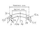
- FIG. 4also shows the area ratios with regard to the optical zone and the so-called treatment zone.
- the incised optical zone 30is so designed that the area difference between the treatment zone that is shown and the optical zone that is shown is larger than the optical zone itself.
- an annular sealing surfacearises (in the treatment zone outside the optical zone) with a contact force, particularly in the region of the undercut 34 , that is greater than the force acting in the optical zone by reason of the internal pressure P.
- Let the treatment zonehave a diameter of 10 mm—that is to say, an area of about 78.5 mm 2 .
- sealing surface in the region of the undercut 34 of about 40 mm 2that is to say, more than the area of the optical zone.
- the sealing surface defined in the above sensedifference between the treatment zone and the optical zone according to FIG. 4
- An upper limit for the sealing surfaceis provided by the geometry of the eye itself and by a type of incision that is meaningful according to the above criteria, so that a numerical figure for this becomes superfluous.
- the type of incision according to FIG. 4permits extremely minimal suturation, which is only required to the extent that a twisting or luxation of the implant is prevented.
Landscapes
- Health & Medical Sciences (AREA)
- Ophthalmology & Optometry (AREA)
- Heart & Thoracic Surgery (AREA)
- Vascular Medicine (AREA)
- Optics & Photonics (AREA)
- Surgery (AREA)
- Engineering & Computer Science (AREA)
- Biomedical Technology (AREA)
- Physics & Mathematics (AREA)
- Nuclear Medicine, Radiotherapy & Molecular Imaging (AREA)
- Life Sciences & Earth Sciences (AREA)
- Animal Behavior & Ethology (AREA)
- General Health & Medical Sciences (AREA)
- Public Health (AREA)
- Veterinary Medicine (AREA)
- Transplantation (AREA)
- Laser Surgery Devices (AREA)
- Prostheses (AREA)
Abstract
Description
Claims (42)
Applications Claiming Priority (3)
| Application Number | Priority Date | Filing Date | Title |
|---|---|---|---|
| DE10124358 | 2001-05-18 | ||
| DE10124358.8 | 2001-05-18 | ||
| DE10124358ADE10124358C1 (en) | 2001-05-18 | 2001-05-18 | Laser system for eye surgery, e.g. cornea transplantation, has laser pulse focus controlled for providing rebated cut within cornea |
Publications (2)
| Publication Number | Publication Date |
|---|---|
| US20020173779A1 US20020173779A1 (en) | 2002-11-21 |
| US6805694B2true US6805694B2 (en) | 2004-10-19 |
Family
ID=7685348
Family Applications (1)
| Application Number | Title | Priority Date | Filing Date |
|---|---|---|---|
| US10/141,902Expired - LifetimeUS6805694B2 (en) | 2001-05-18 | 2002-05-08 | Laser system for corneal grafting |
Country Status (5)
| Country | Link |
|---|---|
| US (1) | US6805694B2 (en) |
| EP (1) | EP1260202B2 (en) |
| AT (1) | ATE302576T1 (en) |
| DE (2) | DE10124358C1 (en) |
| ES (1) | ES2245384T5 (en) |
Cited By (15)
| Publication number | Priority date | Publication date | Assignee | Title |
|---|---|---|---|---|
| US20040243111A1 (en)* | 2003-06-02 | 2004-12-02 | Mark Bendett | Method and apparatus for precision working of material |
| US20060095023A1 (en)* | 2004-11-01 | 2006-05-04 | Frieder Loesel | Time-resolved scanning patterns for intrastromal surgery |
| US20060173445A1 (en)* | 2002-11-13 | 2006-08-03 | Josef Bille | Customized corneal flap |
| US20060195075A1 (en)* | 2003-07-18 | 2006-08-31 | Dirk Muhlhoff | Method and device for forming curved sections in a transparent material |
| US20070208325A1 (en)* | 2006-03-06 | 2007-09-06 | Intralase Corp. | Method of transplanting a cornea |
| US20070244472A1 (en)* | 2006-04-17 | 2007-10-18 | Tobias Kuhn | System and method for creating suture channels |
| US20070293851A1 (en)* | 2003-07-25 | 2007-12-20 | Carl Zeiss Meditec Ag | Method and Device for Producing Curved Cuts in a Transparent Material |
| US20080082086A1 (en)* | 2006-09-05 | 2008-04-03 | Kurtz Ronald M | System and method for resecting corneal tissue |
| US20100087802A1 (en)* | 2007-04-26 | 2010-04-08 | Carl Zeiss Meditec Ag | Cornea transplantation |
| US20100280503A1 (en)* | 2007-03-19 | 2010-11-04 | Christof Donitzky | Laser system that is gentle on the eyes, for refractive surgery |
| US20120150161A1 (en)* | 2007-11-07 | 2012-06-14 | Amo Development, Llc | System and method for incising material |
| US20120150158A1 (en)* | 2010-12-10 | 2012-06-14 | Johannes Krause | Device and process for machining the cornea of a human eye with focused pulsed laser radiation |
| US20150359674A1 (en)* | 2007-11-08 | 2015-12-17 | Carl Zeiss Meditec Ag | Treatment apparatus for operatively correcting defective vision of an eye, method for generating control data therefor, and method for operatively correcting defective vision of an eye |
| US20150366711A1 (en)* | 2007-11-08 | 2015-12-24 | Carl Zeiss Meditec Ag | Treatment apparatus for operatively correcting defective vision of an eye, method for generating control data therefor, and method for operatively correcting defective vision of an eye |
| US11161204B1 (en) | 2020-04-10 | 2021-11-02 | Amnio Technology Llc | Allograft optimization system |
Families Citing this family (12)
| Publication number | Priority date | Publication date | Assignee | Title |
|---|---|---|---|---|
| DE10334108B4 (en)* | 2003-07-25 | 2018-05-09 | Carl Zeiss Meditec Ag | Apparatus for forming a closed, curved cut surface |
| US20060020259A1 (en)* | 2004-07-20 | 2006-01-26 | Klaus Baumeister | System for performing a corneal transplantation |
| US8057463B2 (en)* | 2006-04-07 | 2011-11-15 | Amo Development, Llc. | Adaptive pattern correction for laser scanners |
| WO2009003107A1 (en)* | 2007-06-26 | 2008-12-31 | Bausch & Lomb Incorporated | Method for modifying the refractive index of ocular tissues |
| DE102008026014B4 (en)* | 2008-05-30 | 2019-03-21 | Carl Zeiss Meditec Ag | Surgical system |
| DE102010020194B4 (en) | 2010-05-07 | 2022-09-08 | Carl Zeiss Meditec Ag | Device for stabilizing the cornea |
| EP2648667B1 (en)* | 2010-12-10 | 2016-12-07 | WaveLight GmbH | Device for cutting the cornea of a human eye by means of cuts using focused pulsed laser radiation |
| DE102011085046A1 (en) | 2011-10-21 | 2013-04-25 | Carl Zeiss Meditec Ag | Generation of cut surfaces in a transparent material by means of optical radiation |
| DE102011085047A1 (en) | 2011-10-21 | 2013-04-25 | Carl Zeiss Meditec Ag | Producing cuts in a transparent material by means of optical radiation |
| DE102015002729A1 (en)* | 2015-02-27 | 2016-09-01 | Carl Zeiss Meditec Ag | Ophthalmic laser therapy device and method for generating corneal access incisions |
| IT201800009697A1 (en)* | 2018-10-23 | 2020-04-23 | Edmondo Borasio | OPHTHALMIC SURGERY INSTRUMENT, IN PARTICULAR TO PERFORM A KERATOPLASTIC INTERVENTION USING A DOVETAIL CUTTING PROFILE. |
| IT201800009699A1 (en)* | 2018-10-23 | 2020-04-23 | Edmondo Borasio | OPHTHALMIC SURGERY INSTRUMENT, IN PARTICULAR TO PERFORM A KERATOPLASTIC INTERVENTION BY MEANS OF A SCREW CUT PROFILE. |
Citations (10)
| Publication number | Priority date | Publication date | Assignee | Title |
|---|---|---|---|---|
| US4842599A (en)* | 1986-10-28 | 1989-06-27 | Ann M. Bronstein | Prosthetic cornea and method of implantation therefor |
| US4907586A (en) | 1988-03-31 | 1990-03-13 | Intelligent Surgical Lasers | Method for reshaping the eye |
| WO1993008877A1 (en) | 1991-11-06 | 1993-05-13 | Lai Shui T | Corneal surgery device and method |
| WO1994009849A1 (en) | 1992-10-26 | 1994-05-11 | Swinger Casimir A | Method of performing ophthalmic surgery |
| US5624437A (en) | 1995-03-28 | 1997-04-29 | Freeman; Jerre M. | High resolution, high speed, programmable laser beam modulating apparatus for microsurgery |
| US5647865A (en) | 1991-11-01 | 1997-07-15 | Swinger; Casimir A. | Corneal surgery using laser, donor corneal tissue and synthetic material |
| US5984916A (en) | 1993-04-20 | 1999-11-16 | Lai; Shui T. | Ophthalmic surgical laser and method |
| US5993438A (en) | 1993-11-12 | 1999-11-30 | Escalon Medical Corporation | Intrastromal photorefractive keratectomy |
| US6110166A (en)* | 1995-03-20 | 2000-08-29 | Escalon Medical Corporation | Method for corneal laser surgery |
| EP1138291A2 (en) | 2000-03-27 | 2001-10-04 | Intralase Corporation | A method for preparing an apparatus for corneal surgery |
- 2001
- 2001-05-18DEDE10124358Apatent/DE10124358C1/ennot_activeExpired - Lifetime
- 2002
- 2002-03-11DEDE50204004Tpatent/DE50204004D1/ennot_activeExpired - Lifetime
- 2002-03-11ESES02005281Tpatent/ES2245384T5/ennot_activeExpired - Lifetime
- 2002-03-11EPEP02005281Apatent/EP1260202B2/ennot_activeExpired - Lifetime
- 2002-03-11ATAT02005281Tpatent/ATE302576T1/ennot_activeIP Right Cessation
- 2002-05-08USUS10/141,902patent/US6805694B2/ennot_activeExpired - Lifetime
Patent Citations (10)
| Publication number | Priority date | Publication date | Assignee | Title |
|---|---|---|---|---|
| US4842599A (en)* | 1986-10-28 | 1989-06-27 | Ann M. Bronstein | Prosthetic cornea and method of implantation therefor |
| US4907586A (en) | 1988-03-31 | 1990-03-13 | Intelligent Surgical Lasers | Method for reshaping the eye |
| US5647865A (en) | 1991-11-01 | 1997-07-15 | Swinger; Casimir A. | Corneal surgery using laser, donor corneal tissue and synthetic material |
| WO1993008877A1 (en) | 1991-11-06 | 1993-05-13 | Lai Shui T | Corneal surgery device and method |
| WO1994009849A1 (en) | 1992-10-26 | 1994-05-11 | Swinger Casimir A | Method of performing ophthalmic surgery |
| US5984916A (en) | 1993-04-20 | 1999-11-16 | Lai; Shui T. | Ophthalmic surgical laser and method |
| US5993438A (en) | 1993-11-12 | 1999-11-30 | Escalon Medical Corporation | Intrastromal photorefractive keratectomy |
| US6110166A (en)* | 1995-03-20 | 2000-08-29 | Escalon Medical Corporation | Method for corneal laser surgery |
| US5624437A (en) | 1995-03-28 | 1997-04-29 | Freeman; Jerre M. | High resolution, high speed, programmable laser beam modulating apparatus for microsurgery |
| EP1138291A2 (en) | 2000-03-27 | 2001-10-04 | Intralase Corporation | A method for preparing an apparatus for corneal surgery |
Cited By (40)
| Publication number | Priority date | Publication date | Assignee | Title |
|---|---|---|---|---|
| US20060173445A1 (en)* | 2002-11-13 | 2006-08-03 | Josef Bille | Customized corneal flap |
| US7662149B2 (en)* | 2002-11-13 | 2010-02-16 | Technolas Perfect Vision Gmbh | Customized corneal flap |
| US20080147052A1 (en)* | 2003-06-02 | 2008-06-19 | Carl Zeiss Meditec Ag | Method and apparatus for precision working of material |
| US10898381B2 (en) | 2003-06-02 | 2021-01-26 | Carl Zeiss Meditec Ag | Method and apparatus for precision working of material |
| US9844464B2 (en) | 2003-06-02 | 2017-12-19 | Carl Zeiss Meditec Ag | Method and apparatus for precision working of material |
| US9320650B2 (en) | 2003-06-02 | 2016-04-26 | Carl Zeiss Meditec Ag | Method and apparatus for precision working of an eye |
| US20040243111A1 (en)* | 2003-06-02 | 2004-12-02 | Mark Bendett | Method and apparatus for precision working of material |
| US8171937B2 (en) | 2003-06-02 | 2012-05-08 | Carl Zeiss Meditec Ag | Method and apparatus for precision working of material |
| US7351241B2 (en)* | 2003-06-02 | 2008-04-01 | Carl Zeiss Meditec Ag | Method and apparatus for precision working of material |
| US7921852B2 (en) | 2003-07-18 | 2011-04-12 | Carl Zeiss Meditec Ag | Method and device for forming curved sections in a transparent material |
| US20060195075A1 (en)* | 2003-07-18 | 2006-08-31 | Dirk Muhlhoff | Method and device for forming curved sections in a transparent material |
| US20070293851A1 (en)* | 2003-07-25 | 2007-12-20 | Carl Zeiss Meditec Ag | Method and Device for Producing Curved Cuts in a Transparent Material |
| US10213339B2 (en) | 2003-07-25 | 2019-02-26 | Carl Zeiss Meditec Ag | Method and device for producing curved cuts in a transparent material |
| US11071648B2 (en) | 2003-07-25 | 2021-07-27 | Carl Zeiss Meditec Ag | Method and device for producing curved cuts in a transparent material |
| US20060095023A1 (en)* | 2004-11-01 | 2006-05-04 | Frieder Loesel | Time-resolved scanning patterns for intrastromal surgery |
| US7717905B2 (en)* | 2004-11-01 | 2010-05-18 | Technolas Perfect Vision Gmbh | Time-resolved scanning patterns for intrastromal surgery |
| US20070208325A1 (en)* | 2006-03-06 | 2007-09-06 | Intralase Corp. | Method of transplanting a cornea |
| US10292866B2 (en) | 2006-03-06 | 2019-05-21 | Amo Development, Llc | Method of transplanting a cornea |
| US9402714B2 (en)* | 2006-03-06 | 2016-08-02 | Amo Development, Llc | Method of transplanting a cornea |
| US20070244472A1 (en)* | 2006-04-17 | 2007-10-18 | Tobias Kuhn | System and method for creating suture channels |
| EP3187159A1 (en) | 2006-09-05 | 2017-07-05 | AMO Development, LLC | System for resecting corneal tissue |
| US20080082086A1 (en)* | 2006-09-05 | 2008-04-03 | Kurtz Ronald M | System and method for resecting corneal tissue |
| US20100280503A1 (en)* | 2007-03-19 | 2010-11-04 | Christof Donitzky | Laser system that is gentle on the eyes, for refractive surgery |
| US8728061B2 (en)* | 2007-03-19 | 2014-05-20 | Wavelight Ag | Laser system that is gentle on the eyes, for refractive surgery |
| US10362937B2 (en) | 2007-04-26 | 2019-07-30 | Carl Zeiss Meditec Ag | Cornea transplantation |
| US11154191B2 (en) | 2007-04-26 | 2021-10-26 | Carl Zeiss Meditec Ag | Cornea transplantation |
| US20100087802A1 (en)* | 2007-04-26 | 2010-04-08 | Carl Zeiss Meditec Ag | Cornea transplantation |
| US8292877B2 (en)* | 2007-11-07 | 2012-10-23 | Amo Development, Llc. | System and method for incising material |
| US20120150161A1 (en)* | 2007-11-07 | 2012-06-14 | Amo Development, Llc | System and method for incising material |
| US20150359674A1 (en)* | 2007-11-08 | 2015-12-17 | Carl Zeiss Meditec Ag | Treatment apparatus for operatively correcting defective vision of an eye, method for generating control data therefor, and method for operatively correcting defective vision of an eye |
| US10682256B2 (en)* | 2007-11-08 | 2020-06-16 | Carl Zeiss Meditec Ag | Treatment apparatus for operatively correcting defective vision of an eye, method for generating control data therefor, and method for operatively correcting defective vision of an eye |
| US10327950B2 (en)* | 2007-11-08 | 2019-06-25 | Carl Zeiss Meditec Ag | Treatment apparatus for operatively correcting defective vision of an eye, method for generating control data therefor, and method for operatively correcting defective vision of an eye |
| US20150366711A1 (en)* | 2007-11-08 | 2015-12-24 | Carl Zeiss Meditec Ag | Treatment apparatus for operatively correcting defective vision of an eye, method for generating control data therefor, and method for operatively correcting defective vision of an eye |
| US11357667B2 (en) | 2007-11-08 | 2022-06-14 | Carl Zeiss Meditec Ag | Treatment apparatus for operatively correcting defective vision of an eye, method for generating control data therefor, and method for operatively correcting defective vision of an eye |
| US11602457B2 (en) | 2007-11-08 | 2023-03-14 | Carl Zeiss Meditec Ag | Treatment apparatus for operatively correcting defective vision of an eye, method for generating control data therefor, and method for operatively correcting defective vision of an eye |
| US12011392B2 (en) | 2007-11-08 | 2024-06-18 | Carl Zeiss Meditec Ag | Treatment apparatus for operatively correcting defective vision of an eye, method for generating control data therefor, and method for operatively correcting defective vision of an eye |
| US12433789B2 (en) | 2007-11-08 | 2025-10-07 | Carl Zeiss Meditec Ag | Treatment apparatus for operatively correcting defective vision of an eye, method for generating control data therefor, and method for operatively correcting defective vision of an eye |
| US20120150158A1 (en)* | 2010-12-10 | 2012-06-14 | Johannes Krause | Device and process for machining the cornea of a human eye with focused pulsed laser radiation |
| US11161204B1 (en) | 2020-04-10 | 2021-11-02 | Amnio Technology Llc | Allograft optimization system |
| US11772200B2 (en) | 2020-04-10 | 2023-10-03 | Amnio Technology Llc | Allograft optimization system |
Also Published As
| Publication number | Publication date |
|---|---|
| DE50204004D1 (en) | 2005-09-29 |
| EP1260202B1 (en) | 2005-08-24 |
| US20020173779A1 (en) | 2002-11-21 |
| DE10124358C1 (en) | 2002-10-17 |
| EP1260202A1 (en) | 2002-11-27 |
| ES2245384T5 (en) | 2011-03-01 |
| ATE302576T1 (en) | 2005-09-15 |
| EP1260202B2 (en) | 2010-12-08 |
| ES2245384T3 (en) | 2006-01-01 |
Similar Documents
| Publication | Publication Date | Title |
|---|---|---|
| US6805694B2 (en) | Laser system for corneal grafting | |
| KR101212844B1 (en) | Surgical System | |
| US6325792B1 (en) | Ophthalmic surgical laser and method | |
| US6110166A (en) | Method for corneal laser surgery | |
| EP0484005B1 (en) | Laser thermokeratoplasty apparatus | |
| AU717380B2 (en) | System for corneal reprofiling | |
| AU2016202852B2 (en) | System, interface devices, use of the interface devices and method for eye surgery | |
| US20030014042A1 (en) | Method of creating stromal pockets for corneal implants | |
| WO1994009849A1 (en) | Method of performing ophthalmic surgery | |
| JPS6253650A (en) | Opthalmic operation method and apparatus | |
| KR101651197B1 (en) | Apparatus for assistance in the implantation of a corneal prosthesis in a human eye | |
| US9737438B2 (en) | Device for processing eye tissue by means of pulsed laser beams | |
| CN107072816B (en) | Ophthalmic surgical method | |
| JPH0377553A (en) | Laser reshaping system using light-limiting mask | |
| CA2331223C (en) | A method of corneal surgery by laser incising a contoured corneal flap | |
| US20090012506A1 (en) | Laser mask for creating a corneal pocket | |
| EP0467775B1 (en) | Lens capsule laser cutting apparatus | |
| AU2009343306B2 (en) | Device for cutting a flap in the cornea of an eye | |
| Lubatschowski et al. | Ophthalmic applications | |
| EP1941849A2 (en) | Method for corneal laser surgery | |
| US20120035597A1 (en) | Method for treating incision surfaces in a transparent material | |
| HK1028531A (en) | A universal implant blank for modifying corneal curvature and methods of modifying cornel curvature therewith |
Legal Events
| Date | Code | Title | Description |
|---|---|---|---|
| AS | Assignment | Owner name:WAVELIGHT LASER TECHNOLOGIE AG, GERMANY Free format text:ASSIGNMENT OF ASSIGNORS INTEREST;ASSIGNOR:DONITZKY, CHRISTOF;REEL/FRAME:012888/0505 Effective date:20020301 | |
| STCF | Information on status: patent grant | Free format text:PATENTED CASE | |
| FEPP | Fee payment procedure | Free format text:PAYOR NUMBER ASSIGNED (ORIGINAL EVENT CODE: ASPN); ENTITY STATUS OF PATENT OWNER: LARGE ENTITY | |
| FPAY | Fee payment | Year of fee payment:4 | |
| FEPP | Fee payment procedure | Free format text:PAT HOLDER NO LONGER CLAIMS SMALL ENTITY STATUS, ENTITY STATUS SET TO UNDISCOUNTED (ORIGINAL EVENT CODE: STOL); ENTITY STATUS OF PATENT OWNER: LARGE ENTITY | |
| SULP | Surcharge for late payment | ||
| FPAY | Fee payment | Year of fee payment:8 | |
| FPAY | Fee payment | Year of fee payment:12 | |
| AS | Assignment | Owner name:WAVELIGHT AG, GERMANY Free format text:CHANGE OF NAME;ASSIGNOR:WAVELIGHT LASER TECHNOLOGIE AG;REEL/FRAME:051299/0595 Effective date:20060213 | |
| AS | Assignment | Owner name:WAVELIGHT GMBH, GERMANY Free format text:CHANGE OF NAME;ASSIGNOR:WAVELIGHT AG;REEL/FRAME:051365/0149 Effective date:20100415 | |
| AS | Assignment | Owner name:ALCON INC., SWITZERLAND Free format text:CONFIRMATORY DEED OF ASSIGNMENT EFFECTIVE APRIL 8, 2019;ASSIGNOR:WAVELIGHT GMBH;REEL/FRAME:051381/0854 Effective date:20191111 |