US6804117B2 - Thermal bus for electronics systems - Google Patents
Thermal bus for electronics systemsDownload PDFInfo
- Publication number
- US6804117B2 US6804117B2US10/628,645US62864503AUS6804117B2US 6804117 B2US6804117 B2US 6804117B2US 62864503 AUS62864503 AUS 62864503AUS 6804117 B2US6804117 B2US 6804117B2
- Authority
- US
- United States
- Prior art keywords
- thermal
- interface surface
- thermal interface
- management system
- heat
- Prior art date
- Legal status (The legal status is an assumption and is not a legal conclusion. Google has not performed a legal analysis and makes no representation as to the accuracy of the status listed.)
- Expired - Lifetime
Links
Images


Classifications
- H—ELECTRICITY
- H05—ELECTRIC TECHNIQUES NOT OTHERWISE PROVIDED FOR
- H05K—PRINTED CIRCUITS; CASINGS OR CONSTRUCTIONAL DETAILS OF ELECTRIC APPARATUS; MANUFACTURE OF ASSEMBLAGES OF ELECTRICAL COMPONENTS
- H05K7/00—Constructional details common to different types of electric apparatus
- H05K7/20—Modifications to facilitate cooling, ventilating, or heating
- H05K7/20709—Modifications to facilitate cooling, ventilating, or heating for server racks or cabinets; for data centers, e.g. 19-inch computer racks
- H05K7/208—Liquid cooling with phase change
- H05K7/20818—Liquid cooling with phase change within cabinets for removing heat from server blades
- F—MECHANICAL ENGINEERING; LIGHTING; HEATING; WEAPONS; BLASTING
- F28—HEAT EXCHANGE IN GENERAL
- F28D—HEAT-EXCHANGE APPARATUS, NOT PROVIDED FOR IN ANOTHER SUBCLASS, IN WHICH THE HEAT-EXCHANGE MEDIA DO NOT COME INTO DIRECT CONTACT
- F28D15/00—Heat-exchange apparatus with the intermediate heat-transfer medium in closed tubes passing into or through the conduit walls ; Heat-exchange apparatus employing intermediate heat-transfer medium or bodies
- F28D15/02—Heat-exchange apparatus with the intermediate heat-transfer medium in closed tubes passing into or through the conduit walls ; Heat-exchange apparatus employing intermediate heat-transfer medium or bodies in which the medium condenses and evaporates, e.g. heat pipes
- F28D15/0233—Heat-exchange apparatus with the intermediate heat-transfer medium in closed tubes passing into or through the conduit walls ; Heat-exchange apparatus employing intermediate heat-transfer medium or bodies in which the medium condenses and evaporates, e.g. heat pipes the conduits having a particular shape, e.g. non-circular cross-section, annular
- F—MECHANICAL ENGINEERING; LIGHTING; HEATING; WEAPONS; BLASTING
- F28—HEAT EXCHANGE IN GENERAL
- F28D—HEAT-EXCHANGE APPARATUS, NOT PROVIDED FOR IN ANOTHER SUBCLASS, IN WHICH THE HEAT-EXCHANGE MEDIA DO NOT COME INTO DIRECT CONTACT
- F28D15/00—Heat-exchange apparatus with the intermediate heat-transfer medium in closed tubes passing into or through the conduit walls ; Heat-exchange apparatus employing intermediate heat-transfer medium or bodies
- F28D15/02—Heat-exchange apparatus with the intermediate heat-transfer medium in closed tubes passing into or through the conduit walls ; Heat-exchange apparatus employing intermediate heat-transfer medium or bodies in which the medium condenses and evaporates, e.g. heat pipes
- F28D15/0266—Heat-exchange apparatus with the intermediate heat-transfer medium in closed tubes passing into or through the conduit walls ; Heat-exchange apparatus employing intermediate heat-transfer medium or bodies in which the medium condenses and evaporates, e.g. heat pipes with separate evaporating and condensing chambers connected by at least one conduit; Loop-type heat pipes; with multiple or common evaporating or condensing chambers
- F—MECHANICAL ENGINEERING; LIGHTING; HEATING; WEAPONS; BLASTING
- F28—HEAT EXCHANGE IN GENERAL
- F28D—HEAT-EXCHANGE APPARATUS, NOT PROVIDED FOR IN ANOTHER SUBCLASS, IN WHICH THE HEAT-EXCHANGE MEDIA DO NOT COME INTO DIRECT CONTACT
- F28D15/00—Heat-exchange apparatus with the intermediate heat-transfer medium in closed tubes passing into or through the conduit walls ; Heat-exchange apparatus employing intermediate heat-transfer medium or bodies
- F28D15/02—Heat-exchange apparatus with the intermediate heat-transfer medium in closed tubes passing into or through the conduit walls ; Heat-exchange apparatus employing intermediate heat-transfer medium or bodies in which the medium condenses and evaporates, e.g. heat pipes
- F28D15/0275—Arrangements for coupling heat-pipes together or with other structures, e.g. with base blocks; Heat pipe cores
- H—ELECTRICITY
- H05—ELECTRIC TECHNIQUES NOT OTHERWISE PROVIDED FOR
- H05K—PRINTED CIRCUITS; CASINGS OR CONSTRUCTIONAL DETAILS OF ELECTRIC APPARATUS; MANUFACTURE OF ASSEMBLAGES OF ELECTRICAL COMPONENTS
- H05K7/00—Constructional details common to different types of electric apparatus
- H05K7/20—Modifications to facilitate cooling, ventilating, or heating
- H05K7/20709—Modifications to facilitate cooling, ventilating, or heating for server racks or cabinets; for data centers, e.g. 19-inch computer racks
- H05K7/208—Liquid cooling with phase change
- H05K7/20827—Liquid cooling with phase change within rooms for removing heat from cabinets, e.g. air conditioning devices
Definitions
- the present inventiongenerally relates to heat management systems for high power electronics equipment, and more particularly to a thermal bus system for a cabinet housing high power, high thermal profile electronic components and systems.
- a typical prior art approach to cooling electronic componentsis to direct a stream of cooling air across the modules and/or circuit cards carrying such devices.
- the increasing power density of electronic systemsis reaching the point where it is no longer possible to adequately cool heat generating electronic components by forcing air over them.
- Power densitiesare anticipated to reach the point where it is physically impossible to force sufficient ambient temperature air through a cabinet to adequately cool the electronics inside.
- Several other disadvantages to this approachhave also been identified, including: high pressure drop; uniformity of component form factors; placing the components containing the integrated circuits further apart on the circuit cards; increasing the distance between circuit cards; and increasing the volume and velocity of cooling air directed over the components.
- one techniqueincludes the use of solid metal thermal mounting cards or plates which conduct the heat dissipated by electronic components to a heat sink (cold plate) disposed at the edge of each circuit card.
- a heat sinkcold plate
- Such an approachresults in a large thermal resistance from the component mounting surface to the heat sink, which causes high component temperatures.
- Loop thermosyphonsare devices that use gravity to maintain two-phase fluid circulation during operation.
- Each loop thermosyphonhas an evaporator, where vaporization occurs when it is heated, a vapor tube through which the vapor flows to a condenser where it is cooled and condenses, and a liquid return tube to return the liquid to the evaporator.
- a capillary structureis used in the evaporator to reduce its thermal resistance.
- a heat pipeincludes a sealed envelope that defines an internal chamber containing a capillary wick and a working fluid capable of having both a liquid phase and a vapor phase within a desired range of operating temperatures.
- a working fluidcapable of having both a liquid phase and a vapor phase within a desired range of operating temperatures.
- the working fluidis vaporized in the evaporator section causing a slight pressure increase forcing the vapor to a relatively lower temperature section of the chamber (a condenser section).
- the vaporis condensed in the condenser section and returns through the capillary wick to the evaporator section by capillary pumping action.
- U.S. Pat. No. 4,366,526, issued to Lijol et al.discloses a circuit card for high-density packaging of electronic components for use in high power-density card racks in computer and other electronic and avionic systems.
- the cardhas an all metal construction with an elongate planar body for the mounting of electronic components on opposite sides, and has a heat pipe located along the edges of one elongate side and two ends. Edge tabs on the ends of the card permit the card to be installed into a card rack in electronic equipment.
- the elongate portion of the heat pipeserves as the evaporator section and the two end portions act as the condensing sections.
- U.S. Pat. No. 4,931,905issued to Cirrito et al., discloses two metal plates that have U-shaped grooves so that the plates may form congruent halves wherein matching grooves complete independent heat pipes.
- a bight section of each heat pipeserves as an evaporator section while the parallel arms of each heat pipe form condenser sections.
- a wickis positioned within each heat pipe to improve liquid transport when a module is in a non-upright position.
- the condenser sectionsare located coincident with the normally upright edges of each module so that, when the module is upright, the vertically disposed condenser sections of the heat pipe provide gravity-assisted liquid transport to the evaporator section.
- U.S. Pat. No. 5,283,715issued to Carlsten et al., discloses a heat pipe structure that is incorporated directly into the metal base plate of a circuit card thereby eliminating thermal contact resistance between the base plate and the heat pipe assembly.
- Componentsare mounted on a copper circuit layer bonded to a dielectric layer in a first portion of the base plate with a second portion of the base plate/heat pipe assembly extending into a heat sink/cold plate condensing area for removal of heat generated in the component portion.
- U.S. Pat. No. 6,055,157discloses a computer module that includes a first heat pipe assembly having an evaporator plate with an evaporator surface.
- the first heat pipealso has a condenser in fluid communication with the evaporator plate.
- the evaporator plateis positioned adjacent a printed circuit board populated with at least one electronic component.
- a second heat pipe having the same constructionis positioned adjacent the other side of the printed circuit board so that the electronic components on the other side are positioned adjacent the evaporator surface of the second heat pipe.
- the evaporator plate of each heat pipeis connected to the condenser by a plurality of necked-down regions. This forms at least one window between the condenser and the evaporator plate of each heat pipe. When more than one heat pipe is used in the computing module, the windows of the various heat pipes align.
- U.S. Pat. No. 6,388,882issued to Hoover, et al., discloses a thermal energy management architecture for a functioning system of electronic components and subsystems comprising a hierarchical scheme.
- the thermal management componentsare operatively engaged with individual portions of the system of electronic components and subsystems, in multiple defined levels, and are substantially only thermally driven, i.e., heat transfer devices that have no moving parts and require no external power for their operations.
- U.S. Pat. No. 6,536,510issued to Khrustalev, et al., discloses a thermal bus for cabinets housing high power electronics equipment that includes two spaced-apart horizontally oriented parallel evaporators interconnected in flow communication with a condenser. Each evaporator is mounted in a support having a central recess and each having a tube having a capillary wick disposed on an internal surface and being mounted within the central recess of the support. Each of the tubes includes a closed distal end and a closed proximal end with a liquid-working fluid entrance port located at the closed proximal end of the first tube and a vaporous-working fluid exit port located at the closed proximal end of the second tube.
- a duct defining a central passageway and having a capillary wick disposed on the walls of the central passagewayis disposed in fluid communication with the first tube and the second tube.
- the condenserhas a vaporous-working fluid entrance port disposed in flow communication with the vaporous-working fluid exit port of the evaporator and a liquid-working fluid exit port disposed in flow communication with the liquid-working fluid entrance port of the evaporator so that a working fluid cycles; (i) through the two spaced-apart parallel evaporators, and (ii) between the condenser and the two tubes.
- the present inventionprovides a thermal management system that passively collects waste heat from individual or groups of components and passively transports that heat to a more advantageous location where it can physically be removed by forced air, or to a location inside or outside a cabinet housing the electronic systems, where it can be transferred to an external cooling circuit or sink that may be a significant distance from the electronic system.
- the thermal management system of the present inventionemploys heat pipes and other means to collect heat from components on a circuit card and transport that heat to a thermal connector located on a card shell.
- the thermal management systemprovides a mating thermal connector which is mounted within a cabinet or chassis, and provides the means to transport heat from the circuit card to a location where it can be removed.
- the locationmay be an area within the cabinet where a sufficiently large heat sink can transfer the heat to circulated air, or may be external to the cabinet where heat can be removed by circulating liquid loops or HVAC chiller circuits.
- the present inventionprovides a thermal bus junction arranged within an electronics system for transporting thermal energy in a directed manner from one location to another location by positioning a cold plate, having a portion of at least one heat pipe embedded within a first thermal interface surface of it, adjacent to an evaporator portion of a loop thermosyphon having a second thermal interface surface so that the second thermal interface surface is releasably pressed against the first thermal interface surface.
- a condenser of a first loop thermosyphon having a first thermal interface surfacemay also be arranged adjacent to an evaporator portion of a loop thermosyphon having a second thermal interface surface so that the second thermal interface surface is releasably pressed against the first thermal interface surface.
- a cold plate having a portion of at least one heat pipe embedded within a first thermal interface surface and a condenser of a first loop thermosyphon having a second thermal interface surfacemay be arranged adjacent to an evaporator portion of a second loop thermosyphon having a third thermal interface surface that is releasably pressed against the first and second thermal interface surfaces.
- the present inventionprovides a thermal management system for an electronic device having one or more circuit cards arranged within an enclosure.
- a first thermal energy transfer assemblyis thermally coupled between a heat generating structure located on a circuit card and a first thermal interface surface that is spaced away from the heat generating structure.
- a second thermal energy transfer assemblyincludes a second thermal interface surface which is arranged in confronting relation to the first thermal interface surface.
- a clamping mechanismis arranged to move the second thermal interface surface between (i) a first position that is spaced away from the first thermal interface surface, and (ii) a second position wherein the second thermal interface surface is pressed against the first thermal interface surface so as to allow the busing of thermal energy from the first thermal energy transfer assembly to the second thermal energy transfer assembly by heat transfer from the first thermal interface surface to the second thermal interface surface.
- a thermal management systemhaving at least one card-level cooling assembly including at least one loop thermosyphon having a first thermal interface surface disposed upon a condenser. At least a second loop thermosyphon is provided having a second thermal interface surface disposed upon a second evaporator and arranged in confronting relation to the first thermal interface surface.
- a clamping mechanismis arranged to move the second thermal interface surface between (i) a first position that is spaced away from the first thermal interface surface, and (ii) a second position wherein the second thermal interface surface is pressed against the first thermal interface surface so as to allow the busing of thermal energy from the at least one card-level cooling assembly to the at least a second loop thermosyphon by heat transfer from the first thermal interface surface to the second thermal interface surface.
- a thermal management systemhaving a first thermal energy transfer assembly that is thermally coupled between a heat generating structure located on a circuit card and a first thermal interface surface that is spaced away from the heat generating structure.
- a second thermal energy transfer assemblyis provided that is thermally coupled between a heat generating structure located on a circuit card and a second thermal interface surface that is spaced away from the heat generating structure.
- a third thermal energy transfer assemblyhaving a third thermal interface surface arranged in confronting relation to the first and second thermal interface surfaces.
- a clamping mechanismis arranged to move the third thermal interface surface between (i) a first position that is spaced away from the first and second thermal interface surfaces, and (ii) a second position wherein the third thermal interface surface is pressed against the first and second thermal interface surfaces so as to allow the busing of thermal energy from the first and second thermal energy transfer assemblies to the third thermal energy transfer assembly by heat transfer from the first and second thermal interface surfaces to the third thermal interface surface.
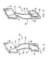
- FIG. 1is an exploded perspective view of a thermal management system formed in accordance with the present invention
- FIG. 2is a perspective view of a first card-level cooling assembly formed in accordance with the present invention.
- FIG. 3is a cross-sectional view of the heat pipe shown in FIG. 2, as taken along lines 3 — 3 in FIG. 2;
- FIG. 4is a broken-away cross-sectional view of the heat pipe and thermal connector shown in FIG. 2, as taken along lines 4 — 4 in FIG. 2;
- FIG. 5is a perspective view of a second card-level cooling assembly formed in accordance with the present invention.
- FIG. 6is rear view of the second card-level cooling assembly shown in FIG. 5;
- FIG. 7is an exploded view of a card shell having first and second card-level cooling assemblies engaged with printed circuit boards located within the shell;
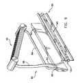
- FIG. 8is a perspective view of a rack-level cooling assembly formed in accordance with the present invention.
- FIG. 9is a perspective rear view of the rack-level cooling assembly shown in FIG. 8, and having a portion of a clamping assembly exploded away for clarity of illustration;
- FIG. 10is a perspective view of an electronic system that is partially populated with a plurality of modular thermal management systems formed in accordance with the present invention.
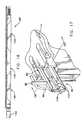
- FIG. 11is a perspective view of an alternative embodiment of evaporator blade and liquid cooled heat exchanger formed in accordance with the present invention.
- FIG. 12is a perspective view of a typical electronic system having the evaporator blade and liquid cooled heat exchanger shown in FIG. 11, assembled therein;
- FIG. 13is a perspective view of the electronic cabinet and thermal management system shown in FIG. 12, housed within a larger enclosure;
- FIG. 14is a further embodiment of the thermal management system of the present invention having a rack-level cooling assembly disposed on the top surface of an enclosure, more than one hundred centimeters from the remainder of the thermal management system;
- FIG. 15is a perspective view, similar to FIG. 14, but with the rack-level cooling assembly positioned on the roof of a building;
- FIG. 16is an elevational view of a typical clamping mechanism used in connection with the present invention.
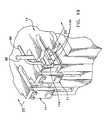
- FIG. 17is a broken-away perspective view of portions of a rack-level cooling assembly and clamping mechanism arranged in accordance with the present invention just prior to full insertion into a rack housing;
- FIG. 18is a broken-away, top elevational view of the present invention showing the first stage in the process of clamping a rack-level cooling assembly evaporator against a thermal connector portion of a card shell in accordance with the present invention
- FIG. 19is a broken-away perspective view of portions of a rack-level cooling assembly and clamping mechanism arranged in accordance with the present invention just after full insertion into a rack housing;
- FIG. 20is a broken-away, top elevational view of the present invention showing the final stage in the process of clamping a rack-level cooling assembly evaporator against a thermal connector portion and thermosyphon condenser portion of a card shell in accordance with the present invention.
- busrefers to the transport of thermal energy in a directed manner from one location to another location, and the structures related to that transference of thermal energy.
- means-plus-function clausesare intended to cover the structures described, suggested, or rendered obvious by the written description or drawings for performing the recited function, including not only structural equivalents but also equivalent structures.
- the present inventionprovides a thermal management system 2 that may be implemented in a functioning electronic system 4 (e.g., a server, local exchange, or the like) comprising electronic components and/or subsystems of such components that are mounted to printed wiring boards 5 .
- a functioning electronic system 4e.g., a server, local exchange, or the like
- One or more printed wiring boards 5are often assembled together within a card shell or pack 11 (also referred to in the art as circuit cards, chassis, cases or “packs”) that is sized and shaped for mounting within a rack housing 14 (FIG. 1 ).
- Card shell 11is sometimes also used to shield against electromagnetic interference (EMI) as well as to provide protection against physical damage or contamination.
- EMIelectromagnetic interference
- Thermal management system 2comprises a hierarchical scheme of heat transfer devices that are operatively engaged with individual or groups of heat generating components that form electronics system 4 .
- electronics system 4the number and constituency of such a thermal management scheme will change, all without deviating from the present invention.
- a thermal management system 2 formed in accordance with the present inventioncomprises a first card-level cooling assembly 16 , a second card-level cooling assembly 18 , and a rack-level cooling assembly 20 .
- first card level cooling assembly 16comprises one or more thermal saddle heat sinks 22 , one or more heat pipes 24 , and a thermal connector 26 .
- Each thermal saddle 22is positioned atop an active, heat generating electronic component, e.g., a processor chip, voltage regulator, power chip, etc. (not shown), to conductively receive operating heat during operation of electronic system 4 .
- a recessed slot 28is defined in the top surface of each thermal saddle 22 so as to receive an evaporator portion of a heat pipe 24 .
- Heat pipes 24comprise a vacuum tight tube 30 , a wick 32 , and a working fluid 34 (FIGS. 2, 3 , and 4 ).
- Tube 30is formed so as to comprise a partially flattened evaporation end 36 and a partially flattened condensation end 38 .
- Tube 30is often a relatively long, somewhat flattened cylinder formed from a thermally conductive material, that is capable of maintaining a vacuum, e.g., copper, aluminum, or their alloys, monel, silicon stainless steel, silicon carbide, or the like,.
- a vapor spaceis defined by a central passageway extending along the longitudinal axis of vacuum tight tube 30 .
- Wick 32may comprise adjacent layers of screening or a sintered powder structure with interstices between the particles of powder.
- Working fluid 34may comprise any of the well known two-phase vaporizable liquids, e.g., water alcohol, freon, etc.
- Heat pipes 24are formed according to the invention by drawing a partial vacuum within tube 30 , and then back-filling with a small quantity of working fluid 34 , e.g., just enough to saturate wick 32 , just prior to final sealing of tube 30 by pinching and welding or otherwise hermetically sealing off both ends 36 and 38 .
- the atmosphere inside heat pipe 30is set by an equilibrium of liquid and vapor generated from working fluid 34 .
- Thermal connector 26comprises an aluminum or copper cold plate 40 that includes one or more channels 42 defined in a first thermal interface surface 44 of thermal management system 2 .
- Cold plate 40is often sized and shaped so as to be mounted within an edge portion of card shell 11 .
- Thermal connector 26comprises a first thermal transfer node via thermal transfer interface surface 44 , between first card-level cooling assembly 16 and rack-level cooling assembly 20 .
- the length of thermal transfer interface surface 44may be approximately the width of card shell 11 , or somewhat smaller, and the exposed height of thermal transfer interface surface 44 is preferably about one and three-quarter inches, often referred to in the art as “1-U” (FIG. 7 ).
- a thermal pad or thermal grease(not shown) may be disposed on thermal transfer interface surface 44 to improve the thermal contact with it.
- a plurality of mounting holes 46are defined through cold plate 40 , and are sized and shaped to accept conventional fasteners.
- channels 42are substantially U-shaped, and have a substantially semi-circular bottom portion that is sized and shaped to tightly receive partially flattened condensation ends 38 of heat pipes 24 (FIG. 4 ).
- Thermal energyis removed from discrete or clusters of heat generating electronic components through thermal saddles 22 , and transported to thermal connector 26 by heat pipes 24 so that heat rejection to the ambient environment, or other heat sinks, may take place outside the vicinity of the circuit card or chassis.
- second card-level cooling assembly 18often comprises a loop thermosyphon 50 that includes an evaporator 52 , a condenser 54 , a vapor conduit 56 , and a condensate conduit 58 .
- a loop thermosyphon 50may be employed for higher power heat sources, since for a given size, loop thermosyphon 50 can transport greater quantities of thermal energy than a heat pipe. Its use also helps to save space on crowded circuit cards.
- Evaporator 52comprises, an inlet opening 62 , and an outlet opening 64 .
- Inlet opening 62is arranged in flow communication with condenser 54 , via condensate conduit 58
- outlet opening 64is arranged in flow communication with condenser 54 , via vapor conduit 56 .
- Evaporator 52is arranged in intimate thermal engagement with a source of thermal energy, such as an integrated circuit chip or chips, or an electronic device comprising such chips or other heat generating structures known in the art and located on a printed wiring board 5 within card shell 11 .
- Evaporator 52may include external and/or internal features and structures to aid in the rapid vaporization of a coolant fluid (not shown).
- an externally applied thermally conductive coatingmay be used to enhance heat transfer and spreading from the heat source throughout evaporator 52
- a sintered internal surface coating or heat pipe structuresmay be included in evaporator 52 for the purpose of spreading and transferring heat, generated by the electronic components, evenly throughout evaporator 52 .
- Loop thermosyphon 50is charged with a suitable coolant fluid, e.g., water, freon, alcohol, acetone, or some other fluid known in the art for use in heat transfer devices, and which is capable of rapid vaporization and condensation within a closed loop environment.
- a suitable coolant fluide.g., water, freon, alcohol, acetone, or some other fluid known in the art for use in heat transfer devices, and which is capable of rapid vaporization and condensation within a closed loop environment.
- Parameters to be considered when selecting a suitable coolant fluidinclude the amount of pressure that can be safely applied to evaporator 52 , the operating temperature of the equipment to be cooled, the rate of heat transfer, the temperatures reached within evaporator 52 , the viscosity of coolant fluid, and the boiling point of coolant fluid.
- Loop thermosyphon 50is sealed to the ambient atmosphere so as to form a closed loop system.
- Evaporator 52acts as a heat exchanger transferring the heat given off by one or a cluster of electronic components to the coolant fluid. As the coolant fluid is heated, the pressure within evaporator 52 increases, vaporizing the coolant fluid. The vapor flows through vapor conduit 56 , toward condenser 54 . Evaporator 52 may comprise many known structures that are suitable for transferring thermal energy to the coolant fluid. Some types of evaporators that have been found to be useful when used in connection with this invention include, tube evaporators, rising film evaporators, falling film evaporators, plate evaporators, and layered wick evaporators. For example, in one embodiment of the invention, evaporator 52 comprises a layered wick evaporator, having a wick formed on its interior surface.
- Vapor conduit 56 and condensate conduit 58may have a conventional structure that is capable of transferring coolant fluid between evaporator 52 and condenser 54 .
- vapor conduit 56 and condensate conduit 58may be separate structures (e.g., tubes or pipes), or may be formed from a single structure, e.g., multiple channels molded or cut into single or multiple blocks.
- Vapor conduit 56 and condensate conduit 58may incorporate flexible sections 59 that permit the conduits to be folded for shipment, and to be bent and reconfigured during installation. The length of each flexible section 59 is determined by the needs of the specific application.
- Condenser 54typically comprises a closed container formed from a thermally conductive material, and defines a second thermal interface surface 69 on an outer side surface.
- Thermal transfer interface surface 69comprises a second thermal transfer node between second card-level cooling assembly 18 and rack-level cooling assembly 20 .
- the length of second thermal transfer interface surface 69is often equal to the difference in length between first thermal transfer interface surface 44 and the width of card shell 11 .
- the exposed height of second thermal interface surface 69is preferably about one and three-quarter inches (FIG. 7 ).
- a thermal pad or thermal greasemay be disposed in the interface area to improve thermal contact.
- An inlet opening 72 and an outlet opening 74are defined in edge portions of condenser 54 .
- Inlet opening 72is arranged in flow communication with evaporator 52 , via vapor conduit 56
- outlet opening 74is arranged in flow communication with evaporator 52 , via condensate conduit 58 .
- Condenser 54acts as a heat exchanger transferring heat contained in a mixture of vaporous coolant fluid and liquid coolant fluid to rack-level cooling assembly 20 .
- rack-level cooling assembly 20also comprises a plurality of modular loop thermosyphons 80 that each include an evaporator 82 , a condenser 84 , a vapor conduit 86 , and a condensate conduit 88 .
- Thermal transport at the rack or cabinet levelis typically provided by a loop thermosyphon-type heat exchanger because of its greater transport capacity.
- Evaporator 82comprises a third thermal transfer interface surface 90 , an inlet opening 92 and an outlet opening 94 .
- Third thermal transfer interface surface 90forms a thermal energy receptacle that is arranged to receive thermal energy from first card-level assembly 16 , via thermal connector 26 , and from second card-level assembly 18 , via condenser 84 .
- the length of third thermal transfer interface surface 90is determined by the total width of card shell 11 (FIG. 7 ).
- the height of third thermal transfer interface surface 90is preferably about one and three-quarter inches.
- third thermal transfer interface surface 90is sized and shaped so as to be complementary to the combined size and shape of first thermal transfer interface surface 44 and second thermal transfer interface surface 69 .
- Evaporator 82may also include external and/or internal features and structures to aid in the rapid vaporization of a coolant fluid (not shown) such as an externally applied thermally conductive coating to enhance heat transfer, or a sintered internal surface coating or heat pipe structures for spreading and transferring heat evenly throughout evaporator 82 .
- a multiple card evaporator 96includes a plurality of blade-evaporators 98 that extend from a common manifold 100 that is arranged in fluid communication with each blade-evaporator 98 .
- a single loop thermosyphonserves all the cards in a chassis or rack housing 14 .
- Plurality of blade-evaporators 98are often arranged in substantially perpendicular relation to common manifold 100 , but are otherwise substantially similar to evaporator 82 in structure, components, and function. In this way, multiple card evaporator 96 provides one evaporator blade for each card shell 11 that can fit in rack housing 14 .
- Each blade-evaporator 98may contain a wick disposed on its interior surfaces.
- Blade-evaporators 98 of multiple card evaporator 96are joined into common header manifold 100 so vapor exits the evaporators from a single vapor line 105 .
- a single liquid line 106returns condensate to common header manifold 100 which distributes the liquid to the individual blade-evaporators 98 .
- Vapor line 105 and liquid line 106incorporate flexible sections 107 to aid in installation.
- Each individual blade-evaporator 98has the same interface geometry as evaporator 82 . Although shown in the figures as a rigid extension of common header manifold 100 , the blade/manifold interface 109 may employ flexible joint connections.
- Loop thermosyphon 80is also charged with a suitable coolant fluid, e.g., water, freon, alcohol, acetone, or some other fluid known in the art for use in heat transfer devices, and which is capable of rapid vaporization and condensation within a closed loop environment. Loop thermosyphon 80 is sealed from the ambient atmosphere so as to form a closed loop system. As coolant fluid is heated, the pressure within evaporator 82 increases, vaporizing the saturated fluid. The vapor flows through vapor conduit 86 , toward condenser 84 . Evaporator 82 may comprise many known structures that are suitable for transferring thermal energy to the coolant fluid. Some types of evaporators that have been found to be useful when used in connection with this invention include, tube evaporators, rising film evaporators, falling film evaporators, plate evaporators, and layered wick evaporators.
- a suitable coolant fluide.g., water, freon, alcohol, acetone, or some other fluid known in the art for
- Vapor conduit 86 and condensate conduit 88may have a conventional structure that is capable of transferring coolant fluid between evaporator 82 and condenser 84 .
- vapor conduit 86 and condensate conduit 88may be separate structures (e.g., tubes or pipes), or may be formed from a single structure, e.g., multiple channels molded or cut into single or multiple blocks.
- Vapor conduit 86 and condensate conduit 88may have varying lengths, and incorporate flexible sections 89 that permit the conduits to be folded for shipment, and to be bent and reconfigured during installation.
- condenser 84comprises a vapor vessel 110 , a liquid vessel 112 , a plurality of conduits 114 , and a plurality of fins 116 , all formed from a suitably thermally conductive material.
- Vapor vessel 110includes an inlet opening 120 and liquid vessel 112 includes an outlet opening 122 .
- Inlet opening 120is arranged in flow communication with evaporator 82 , via outlet opening 94
- outlet opening 122is arranged in flow communication with evaporator 82 , via inlet opening 92 .
- Plurality of conduits 114comprise hollow, rectangular tubes that are arranged in spaced, parallel relation to one another, and in flow communication between vapor vessel 110 and liquid vessel 112 .
- Plurality of fins 116are positioned between adjacent conduits 114 so as to increase the available thermal conductor surface area and thereby enhance the transfer of thermal energy from vaporous and liquid coolant flowing between vapor vessel 110 and liquid vessel 112 under the force of gravity.
- Condenser 84acts as a heat exchanger transferring heat contained in a mixture of vaporous coolant fluid and liquid coolant fluid to the ambient environment via convection. If sufficient space is available immediately above the rack containing card shells 11 , then a modular system incorporating air cooled heat sinks such as condenser 84 are preferred (FIGS. 1 and 10 ). Condenser 84 may be located inside or outside of a cabinet or enclosure 124 . If the heat is to be transferred to air, external locations that are spaced far away, i.e., by more than one hundred centimeters, allow the use of very large condensers 84 on, e.g., the roof 126 of a building, so heat may be efficiently dumped to the ambient air (FIG. 15 ).
- rack housing 14is not fully filled with card shells 11 at initial installation.
- a rack housing 14which accommodates, e.g., nine card shells, may be initially delivered with only three.
- the modularity of rack-level cooling assembly 20permits individual installation so the initial number of loop thermosyphons matches the number of card shells 11 .
- Additional loop thermosyphons 80can be plugged in at any time when additional card shells 11 are added to rack housing 14 .
- Thermal engagement clamp assembly 95may be thermally, but releasably engaged with first card-level cooling assembly 16 and second card-level cooling assembly 18 by thermal engagement clamp assembly 95 (FIGS. 9 and 16 ). More particularly, thermal engagement clamp assembly 95 often comprises a wedge-lock type of clamp, e.g. the “card-lok” clamp manufactured by Calmark Corp of San Gabriel Calif., and disclosed in U.S. Pat. Nos. 5,224,016 and 4,819,713, which patents are hereby incorporated herein by reference. Typically thermal engagement clamp assembly 95 includes a plurality of trapazoidally shaped wedge members 140 that are arranged in an end to end fashion with successive wedge members being oppositely oriented.
- a reasonable clamping pressureis essential to providing good thermal connections, but clamping must not be allowed to interfere with the insertion of a card shell 11 , or with the making of electrical connections when the card is inserted.
- Releasing lever 144removes the force holding wedges 140 , thereby providing clearance for zero-interference removal of card shell 11 .
- thermosyphon 80allows a more efficient air flow than could be forced through the constricted space between card shells 11 , and also permits the use of fin stacks (heat exchangers) that are much larger than could be mounted on or near the components being cooled.
- fin stacksheat exchangers
- heat exchangersheat exchangers
- a conventional liquid cooled condenser 130may be used when an air cooled condenser cannot be easily mounted on or near to electronic system 4 , or will not have the capacity to handle the thermal energy transferred to it.
- Liquid cooled condenser 130can utilize a circulating coolant, such as water or water/ethylene-glycol, or can be the chiller circuit of an HVAC system. Liquid cooled condensers 130 can also be very compact, and would generally be mounted to the outside of the cabinet housing electronics system 4 , so that coolant is never introduced into the electronic rack housing 14 . Such systems are often sized to dissipate about five kilowatts or so. With this embodiment of the invention, the cabinet can be hermetically sealed to avoid contamination by dust and dirt.
- a circulating coolantsuch as water or water/ethylene-glycol
- a compact liquid cooled condenser 130combined with flexible sections 107 in the liquid and vapor lines allows a rack/chassis incorporating a thermal management system 2 to be modularly installed in an existing rack cabinet 14 .
- the only physical change to the cabinet, other than mounting provisions,is cutting a slot in the rear panel of the cabinet.
Landscapes
- Engineering & Computer Science (AREA)
- Physics & Mathematics (AREA)
- Thermal Sciences (AREA)
- General Engineering & Computer Science (AREA)
- Life Sciences & Earth Sciences (AREA)
- Sustainable Development (AREA)
- Mechanical Engineering (AREA)
- Computer Hardware Design (AREA)
- Microelectronics & Electronic Packaging (AREA)
- Cooling Or The Like Of Electrical Apparatus (AREA)
Abstract
Description
Claims (38)
Priority Applications (6)
| Application Number | Priority Date | Filing Date | Title |
|---|---|---|---|
| US10/628,645US6804117B2 (en) | 2002-08-14 | 2003-07-28 | Thermal bus for electronics systems |
| AU2003294213AAU2003294213A1 (en) | 2002-08-14 | 2003-08-13 | Thermal bus for electronics systems |
| PCT/US2003/025201WO2004031673A2 (en) | 2002-08-14 | 2003-08-13 | Thermal bus for electronics systems |
| US10/786,431US7013955B2 (en) | 2003-07-28 | 2004-02-25 | Flexible loop thermosyphon |
| US11/210,548US7096928B2 (en) | 2003-07-28 | 2005-08-23 | Flexible loop thermosyphon |
| US11/461,878US20060254753A1 (en) | 2003-07-28 | 2006-08-02 | Flexible loop thermosyphon |
Applications Claiming Priority (2)
| Application Number | Priority Date | Filing Date | Title |
|---|---|---|---|
| US40344402P | 2002-08-14 | 2002-08-14 | |
| US10/628,645US6804117B2 (en) | 2002-08-14 | 2003-07-28 | Thermal bus for electronics systems |
Related Child Applications (2)
| Application Number | Title | Priority Date | Filing Date |
|---|---|---|---|
| US10/786,431Continuation-In-PartUS7013955B2 (en) | 2003-07-28 | 2004-02-25 | Flexible loop thermosyphon |
| US11/461,878Continuation-In-PartUS20060254753A1 (en) | 2003-07-28 | 2006-08-02 | Flexible loop thermosyphon |
Publications (2)
| Publication Number | Publication Date |
|---|---|
| US20040037045A1 US20040037045A1 (en) | 2004-02-26 |
| US6804117B2true US6804117B2 (en) | 2004-10-12 |
Family
ID=31891382
Family Applications (1)
| Application Number | Title | Priority Date | Filing Date |
|---|---|---|---|
| US10/628,645Expired - LifetimeUS6804117B2 (en) | 2002-08-14 | 2003-07-28 | Thermal bus for electronics systems |
Country Status (3)
| Country | Link |
|---|---|
| US (1) | US6804117B2 (en) |
| AU (1) | AU2003294213A1 (en) |
| WO (1) | WO2004031673A2 (en) |
Cited By (71)
| Publication number | Priority date | Publication date | Assignee | Title |
|---|---|---|---|---|
| US20030051859A1 (en)* | 2001-09-20 | 2003-03-20 | Chesser Jason B. | Modular capillary pumped loop cooling system |
| US20030098588A1 (en)* | 2001-11-26 | 2003-05-29 | Kazuaki Yazawa | Method and apparatus for converting dissipated heat to work energy |
| US20050103477A1 (en)* | 2003-11-14 | 2005-05-19 | Lg Electronics Inc. | Cooling apparatus for portable computer |
| US20050122686A1 (en)* | 2003-12-05 | 2005-06-09 | Nec Corporation | Electronic card unit and method for removing heat from a heat-generating component on a printed circuit board |
| US20050138440A1 (en)* | 2003-12-18 | 2005-06-23 | Barr Andrew H. | Equipment rack load modulation system and method |
| US20050219820A1 (en)* | 2004-04-01 | 2005-10-06 | Belady Christian L | System and method for heat dissipation |
| US20050248922A1 (en)* | 2004-05-07 | 2005-11-10 | International Business Machines Corporation | Cooling assembly for electronics drawer using passive fluid loop and air-cooled cover |
| US20060146496A1 (en)* | 2005-01-06 | 2006-07-06 | The Boeing Company | Cooling apparatus, system, and associated method |
| US20060254753A1 (en)* | 2003-07-28 | 2006-11-16 | Phillips Alfred L | Flexible loop thermosyphon |
| US20060272798A1 (en)* | 2005-06-03 | 2006-12-07 | Tay-Jian Liu | Loop-type heat exchange device |
| US20070042514A1 (en)* | 2005-08-22 | 2007-02-22 | Shan Ping Wu | Method and apparatus for cooling a blade server |
| US20070095507A1 (en)* | 2005-09-16 | 2007-05-03 | University Of Cincinnati | Silicon mems based two-phase heat transfer device |
| US20070199332A1 (en)* | 2003-12-23 | 2007-08-30 | Christian Muller | Heat Exchanger |
| US20070256957A1 (en)* | 2006-05-06 | 2007-11-08 | Schroff Gmbh | Sub-rack with housing for receiving plug-in modules |
| US20080013283A1 (en)* | 2006-07-17 | 2008-01-17 | Gilbert Gary L | Mechanism for cooling electronic components |
| US20080087406A1 (en)* | 2006-10-13 | 2008-04-17 | The Boeing Company | Cooling system and associated method for planar pulsating heat pipe |
| US20080093052A1 (en)* | 2006-10-20 | 2008-04-24 | Foxconn Technology Co., Ltd. | Heat dissipation device with heat pipes |
| US20080212265A1 (en)* | 2007-01-23 | 2008-09-04 | Paul Mazura | Switchgear Cabinet for Accommodating Electronic Plug-In Modules with a Heat Exchanger |
| US20080218980A1 (en)* | 2007-03-05 | 2008-09-11 | Tracewell Systems, Inc. | Method and system for dissipating thermal energy from conduction-cooled circuit card assemblies which employ remote heat sinks and heat pipe technology |
| WO2008131041A1 (en)* | 2007-04-16 | 2008-10-30 | Steve Fried | Efficiently cool data centers and electronics housed in electronics |
| US7457118B1 (en)* | 2003-12-19 | 2008-11-25 | Emc Corporation | Method and apparatus for dispersing heat from high-power electronic devices |
| US20090027856A1 (en)* | 2007-07-26 | 2009-01-29 | Mccoy Scott | Blade cooling system using wet and dry heat sinks |
| US20090154104A1 (en)* | 2007-12-14 | 2009-06-18 | Yoshihiro Kondo | Cooling Device and Electronic Apparatus Using the Same |
| US20090159240A1 (en)* | 2007-12-20 | 2009-06-25 | Chung-Jun Chu | Mobile cooling structure and machine case having the same |
| US20090318071A1 (en)* | 2006-12-21 | 2009-12-24 | Nemoz Gerard | Electronic equipment housing cooled by natural and forced ventilation |
| US20100020504A1 (en)* | 2008-07-22 | 2010-01-28 | Shih-Ho Chang | Electronic device and heat dissipation unit thereof |
| US20100038660A1 (en)* | 2008-08-13 | 2010-02-18 | Progressive Cooling Solutions, Inc. | Two-phase cooling for light-emitting devices |
| US20100073863A1 (en)* | 2008-09-24 | 2010-03-25 | Hitachi, Ltd. | Electronic apparatus |
| US20100128439A1 (en)* | 2008-11-24 | 2010-05-27 | General Electric Company | Thermal management system with graphene-based thermal interface material |
| US20100132404A1 (en)* | 2008-12-03 | 2010-06-03 | Progressive Cooling Solutions, Inc. | Bonds and method for forming bonds for a two-phase cooling apparatus |
| US20100236761A1 (en)* | 2009-03-19 | 2010-09-23 | Acbel Polytech Inc. | Liquid cooled heat sink for multiple separated heat generating devices |
| US20100270010A1 (en)* | 2009-04-28 | 2010-10-28 | Abb Research Ltd | Twisted tube thermosyphon |
| US20100277870A1 (en)* | 2009-04-29 | 2010-11-04 | Abb Research Ltd | Multi-row thermosyphon heat exchanger |
| US20100277864A1 (en)* | 2009-04-29 | 2010-11-04 | Tozer Robert | Cooling |
| US20100296250A1 (en)* | 2009-05-22 | 2010-11-25 | Chiu-Mao Huang | Heat dissipation device for communication chassis |
| US20100326627A1 (en)* | 2009-06-30 | 2010-12-30 | Schon Steven G | Microelectronics cooling system |
| US20110141692A1 (en)* | 2007-12-31 | 2011-06-16 | Jeff Bult | Conduction cooled circuit board assembly |
| US20120039036A1 (en)* | 2009-10-30 | 2012-02-16 | Krause Michael R | Thermal bus bar for a blade enclosure |
| US20120140403A1 (en)* | 2010-12-01 | 2012-06-07 | Google Inc. | Cooling heat-generating electronics |
| US20120170224A1 (en)* | 2010-12-29 | 2012-07-05 | Src, Inc. | Circuit board frame with integral heat sink for enhanced thermal transfer |
| US20120279683A1 (en)* | 2011-05-05 | 2012-11-08 | Alcatel-Lucent Usa Inc. | Cooling apparatus for communications platforms |
| US20130003316A1 (en)* | 2010-12-28 | 2013-01-03 | Elma Electronic Inc. | Card Lock Retainer For Pluggable Conduction Cooled Circuit Card Assemblies |
| US20130135822A1 (en)* | 2011-11-25 | 2013-05-30 | Inventec Corporation | Cooling module |
| US20130204440A1 (en)* | 2010-11-19 | 2013-08-08 | Nest Labs, Inc. | Hvac controller with user-friendly installation features with wire insertion detection |
| US8544285B2 (en)* | 2010-11-19 | 2013-10-01 | Nest Labs, Inc. | HVAC controller with user-friendly installation features facilitating both do-it-yourself and professional installation scenarios |
| US20130322024A1 (en)* | 2010-12-17 | 2013-12-05 | Thales | Cooling an electronic device |
| US20140198457A1 (en)* | 2013-01-15 | 2014-07-17 | Emerson Network Power - Embedded Computing, Inc. | Integrated Thermal Inserts And Cold Plate |
| US20140221214A1 (en)* | 2011-09-08 | 2014-08-07 | Siemens Aktiengesellschaft | Device and method for cooling a unit |
| US8893513B2 (en) | 2012-05-07 | 2014-11-25 | Phononic Device, Inc. | Thermoelectric heat exchanger component including protective heat spreading lid and optimal thermal interface resistance |
| US8991194B2 (en) | 2012-05-07 | 2015-03-31 | Phononic Devices, Inc. | Parallel thermoelectric heat exchange systems |
| US9003816B2 (en) | 2010-11-19 | 2015-04-14 | Google Inc. | HVAC controller with user-friendly installation features facilitating both do-it-yourself and professional installation scenarios |
| US9116529B2 (en) | 2011-02-24 | 2015-08-25 | Google Inc. | Thermostat with self-configuring connections to facilitate do-it-yourself installation |
| US20150327402A1 (en)* | 2014-05-09 | 2015-11-12 | Advanced Cooling Technologies, Inc. | Heat management for electronic enclosures |
| US9398731B1 (en) | 2014-09-23 | 2016-07-19 | Google Inc. | Cooling electronic devices in a data center |
| US9494332B2 (en) | 2010-09-14 | 2016-11-15 | Google Inc. | Thermostat wiring connector |
| US9593871B2 (en) | 2014-07-21 | 2017-03-14 | Phononic Devices, Inc. | Systems and methods for operating a thermoelectric module to increase efficiency |
| US20180080685A1 (en)* | 2007-12-28 | 2018-03-22 | Steven Schon | Microelectronics cooling system |
| US20180172364A1 (en)* | 2015-06-03 | 2018-06-21 | Danfoss Micro Channel Heat Exchanger (Jiaxing) Co., Ltd. | Heat exchanger system |
| US10136557B2 (en) | 2015-12-04 | 2018-11-20 | General Electric Company | Thermal management systems and methods for heat generating electronics |
| US10209003B2 (en) | 2012-02-21 | 2019-02-19 | Thermal Corp. | Electronics cabinet and rack cooling system and method |
| US10349561B2 (en) | 2016-04-15 | 2019-07-09 | Google Llc | Cooling electronic devices in a data center |
| US20190264988A1 (en)* | 2018-02-27 | 2019-08-29 | Shinko Electric Industries Co., Ltd. | Loop type heat pipe |
| US10448543B2 (en) | 2015-05-04 | 2019-10-15 | Google Llc | Cooling electronic devices in a data center |
| US10452083B2 (en) | 2010-11-19 | 2019-10-22 | Google Llc | Power management in single circuit HVAC systems and in multiple circuit HVAC systems |
| US10462935B2 (en) | 2015-06-23 | 2019-10-29 | Google Llc | Cooling electronic devices in a data center |
| US10458683B2 (en) | 2014-07-21 | 2019-10-29 | Phononic, Inc. | Systems and methods for mitigating heat rejection limitations of a thermoelectric module |
| US10638648B2 (en) | 2016-04-28 | 2020-04-28 | Ge Energy Power Conversion Technology Ltd. | Cooling system with pressure regulation |
| US10732651B2 (en) | 2010-11-19 | 2020-08-04 | Google Llc | Smart-home proxy devices with long-polling |
| US10989453B2 (en)* | 2019-02-27 | 2021-04-27 | Auras Technology Co., Ltd. | Heat exchanger with improved heat removing efficiency |
| WO2021174319A1 (en)* | 2020-03-06 | 2021-09-10 | NetComm Wireless Pty Ltd | Telecommunications housing with improved thermal load management |
| US11678463B2 (en)* | 2017-12-07 | 2023-06-13 | Siemens Mobility GmbH | Fanless cooling system |
Families Citing this family (37)
| Publication number | Priority date | Publication date | Assignee | Title |
|---|---|---|---|---|
| DE10335197B4 (en)* | 2003-07-30 | 2005-10-27 | Kermi Gmbh | Cooling device for an electronic component, in particular for a microprocessor |
| DE102004054337B4 (en)* | 2004-11-09 | 2007-01-11 | Rittal Res Electronic Systems Gmbh & Co. Kg | cooling arrangement |
| DE102005016115B4 (en)* | 2005-04-08 | 2007-12-20 | Rittal Gmbh & Co. Kg | Arrangement for cooling an electronic device |
| US7483271B2 (en)* | 2005-05-19 | 2009-01-27 | Bae Systems Information And Electronic Systems Integration Inc. | High density card retention device |
| US7542293B2 (en)* | 2006-04-10 | 2009-06-02 | Fu Zhun Precision Industry (Shen Zhen) Co., Ltd. | Thermal module |
| WO2008109805A2 (en)* | 2007-03-07 | 2008-09-12 | Asetek Usa Inc. | Hybrid liquid-air cooled graphics display adapter |
| EP2061296B1 (en)* | 2007-11-16 | 2014-05-14 | GE Aviation Systems LLC | Conduction cooled circuit board assembly |
| TW200930963A (en)* | 2008-01-02 | 2009-07-16 | Rui-Zhao Chen | Combination refrigerator |
| US20090323276A1 (en)* | 2008-06-25 | 2009-12-31 | Mongia Rajiv K | High performance spreader for lid cooling applications |
| CN101742875B (en)* | 2008-11-20 | 2011-10-05 | 英业达股份有限公司 | Cooling components |
| US7903404B2 (en)* | 2009-04-29 | 2011-03-08 | Hewlett-Packard Development Company, L.P. | Data centers |
| US8526184B2 (en)* | 2009-09-09 | 2013-09-03 | Curtiss-Wright Controls, Inc. | Devices having a thermal interface and methods of forming the same |
| JP4802272B2 (en)* | 2009-09-30 | 2011-10-26 | 株式会社東芝 | Electronics |
| JP5445507B2 (en)* | 2010-06-03 | 2014-03-19 | 株式会社デンソー | Power converter |
| TWM412341U (en)* | 2011-04-01 | 2011-09-21 | Academia Sinica | Cooling system for electronic instrument cabinet |
| US9609786B2 (en)* | 2011-04-01 | 2017-03-28 | Academia Sinica | Cooling system for an electronic rack |
| US8811014B2 (en) | 2011-12-29 | 2014-08-19 | General Electric Company | Heat exchange assembly and methods of assembling same |
| US8780559B2 (en) | 2011-12-29 | 2014-07-15 | General Electric Company | Heat exchange assembly for use with electrical devices and methods of assembling an electrical device |
| US9921003B2 (en)* | 2012-01-19 | 2018-03-20 | Lockheed Martin Corporation | Wickless heat pipe and thermal ground plane |
| US9366394B2 (en)* | 2012-06-27 | 2016-06-14 | Flextronics Ap, Llc | Automotive LED headlight cooling system |
| FR3002411B1 (en)* | 2013-02-20 | 2015-03-06 | Bull Sas | THERMAL DISSIPATOR FOR PROCESSOR |
| WO2014131460A1 (en)* | 2013-02-28 | 2014-09-04 | Klondike Innovations Limited | Cooling heat generating components |
| JP6605819B2 (en)* | 2015-03-06 | 2019-11-13 | 株式会社東芝 | Cooling system |
| CN105101753B (en)* | 2015-08-12 | 2017-08-29 | 东莞市努谢尔环境设备科技有限公司 | A kind of aluminium section bar and its loop heat pipe system and electric heat sinking back-plate |
| US10634397B2 (en) | 2015-09-17 | 2020-04-28 | Purdue Research Foundation | Devices, systems, and methods for the rapid transient cooling of pulsed heat sources |
| JP6852352B2 (en)* | 2016-11-07 | 2021-03-31 | 富士通株式会社 | Loop heat pipes and electronics |
| US10631434B2 (en)* | 2017-02-01 | 2020-04-21 | J R Thermal LLC | Self-priming thermosyphon |
| GB2575661B (en)* | 2018-07-18 | 2020-08-19 | Flint Eng Ltd | Thermal management system |
| EP3953658A1 (en)* | 2019-04-10 | 2022-02-16 | MBDA UK Limited | Missile comprising electronics and a jumping-drop vapour chamber |
| US11291143B2 (en)* | 2019-12-27 | 2022-03-29 | Baidu Usa Llc | Cooling design for electronics enclosure |
| US11920869B2 (en)* | 2020-02-19 | 2024-03-05 | Continental Automotive Systems, Inc. | Balanced heat transfer mechanism and control for automotive vehicles communication systems |
| CN112050673B (en)* | 2020-09-08 | 2021-09-24 | 中国矿业大学 | A pulsating heat pipe with an equal split structure |
| WO2022144453A1 (en)* | 2021-01-04 | 2022-07-07 | Eaton Intelligent Power Limited | High-efficiency thermal management system and thermal exchange device |
| EP4181642A1 (en)* | 2021-11-16 | 2023-05-17 | JJ Cooling Innovation Sàrl | Cooling system for electronic component racks |
| US12369271B2 (en)* | 2022-09-30 | 2025-07-22 | Lenovo Global Technology (United States) Inc. | Cooling systems having a conduit and a heat transfer device for transferring heat from an electronic component |
| US12238904B2 (en) | 2022-12-16 | 2025-02-25 | Bae Systems Controls Inc. | Cooling system with common modular manifolds |
| KR20250136811A (en)* | 2023-01-23 | 2025-09-16 | 미크로스 테크놀로지스 엘엘씨 | Heat exchanger for high-performance chipsets |
Citations (15)
| Publication number | Priority date | Publication date | Assignee | Title |
|---|---|---|---|---|
| US4366526A (en) | 1980-10-03 | 1982-12-28 | Grumman Aerospace Corporation | Heat-pipe cooled electronic circuit card |
| US4449576A (en)* | 1980-11-25 | 1984-05-22 | Kabel- Und Metallwerke | Heat-producing elements with heat pipes |
| US4819713A (en) | 1987-04-23 | 1989-04-11 | Calmark Corporation | Retainer for electronic modules |
| US4931905A (en) | 1989-01-17 | 1990-06-05 | Grumman Aerospace Corporation | Heat pipe cooled electronic circuit card |
| US5224016A (en) | 1990-05-31 | 1993-06-29 | Calmark Corporation | Retainer for electronic modules |
| US5283715A (en) | 1992-09-29 | 1994-02-01 | International Business Machines, Inc. | Integrated heat pipe and circuit board structure |
| US5829516A (en) | 1993-12-15 | 1998-11-03 | Aavid Thermal Products, Inc. | Liquid cooled heat sink for cooling electronic components |
| US5884693A (en) | 1997-12-31 | 1999-03-23 | Dsc Telecom L.P. | Integral heat pipe enclosure |
| US5890371A (en) | 1996-07-12 | 1999-04-06 | Thermotek, Inc. | Hybrid air conditioning system and a method therefor |
| US6055157A (en) | 1998-04-06 | 2000-04-25 | Cray Research, Inc. | Large area, multi-device heat pipe for stacked MCM-based systems |
| US6388882B1 (en) | 2001-07-19 | 2002-05-14 | Thermal Corp. | Integrated thermal architecture for thermal management of high power electronics |
| US6536510B2 (en) | 2001-07-10 | 2003-03-25 | Thermal Corp. | Thermal bus for cabinets housing high power electronics equipment |
| US6621713B2 (en)* | 2000-07-19 | 2003-09-16 | Internet Research Institute, Inc. | Cartridge type server unit and a cabinet to accommodate multiple said server units |
| US6643132B2 (en)* | 2002-01-04 | 2003-11-04 | Intel Corporation | Chassis-level thermal interface component for transfer of heat from an electronic component of a computer system |
| US6657121B2 (en)* | 2001-06-27 | 2003-12-02 | Thermal Corp. | Thermal management system and method for electronics system |
- 2003
- 2003-07-28USUS10/628,645patent/US6804117B2/ennot_activeExpired - Lifetime
- 2003-08-13AUAU2003294213Apatent/AU2003294213A1/ennot_activeAbandoned
- 2003-08-13WOPCT/US2003/025201patent/WO2004031673A2/ennot_activeApplication Discontinuation
Patent Citations (16)
| Publication number | Priority date | Publication date | Assignee | Title |
|---|---|---|---|---|
| US4366526A (en) | 1980-10-03 | 1982-12-28 | Grumman Aerospace Corporation | Heat-pipe cooled electronic circuit card |
| US4449576A (en)* | 1980-11-25 | 1984-05-22 | Kabel- Und Metallwerke | Heat-producing elements with heat pipes |
| US4819713A (en) | 1987-04-23 | 1989-04-11 | Calmark Corporation | Retainer for electronic modules |
| US4931905A (en) | 1989-01-17 | 1990-06-05 | Grumman Aerospace Corporation | Heat pipe cooled electronic circuit card |
| US5224016A (en) | 1990-05-31 | 1993-06-29 | Calmark Corporation | Retainer for electronic modules |
| US5283715A (en) | 1992-09-29 | 1994-02-01 | International Business Machines, Inc. | Integrated heat pipe and circuit board structure |
| US5829516A (en) | 1993-12-15 | 1998-11-03 | Aavid Thermal Products, Inc. | Liquid cooled heat sink for cooling electronic components |
| US5890371A (en) | 1996-07-12 | 1999-04-06 | Thermotek, Inc. | Hybrid air conditioning system and a method therefor |
| US5884693A (en) | 1997-12-31 | 1999-03-23 | Dsc Telecom L.P. | Integral heat pipe enclosure |
| US6076595A (en) | 1997-12-31 | 2000-06-20 | Alcatel Usa Sourcing, L.P. | Integral heat pipe enclosure |
| US6055157A (en) | 1998-04-06 | 2000-04-25 | Cray Research, Inc. | Large area, multi-device heat pipe for stacked MCM-based systems |
| US6621713B2 (en)* | 2000-07-19 | 2003-09-16 | Internet Research Institute, Inc. | Cartridge type server unit and a cabinet to accommodate multiple said server units |
| US6657121B2 (en)* | 2001-06-27 | 2003-12-02 | Thermal Corp. | Thermal management system and method for electronics system |
| US6536510B2 (en) | 2001-07-10 | 2003-03-25 | Thermal Corp. | Thermal bus for cabinets housing high power electronics equipment |
| US6388882B1 (en) | 2001-07-19 | 2002-05-14 | Thermal Corp. | Integrated thermal architecture for thermal management of high power electronics |
| US6643132B2 (en)* | 2002-01-04 | 2003-11-04 | Intel Corporation | Chassis-level thermal interface component for transfer of heat from an electronic component of a computer system |
Cited By (128)
| Publication number | Priority date | Publication date | Assignee | Title |
|---|---|---|---|---|
| US6981543B2 (en)* | 2001-09-20 | 2006-01-03 | Intel Corporation | Modular capillary pumped loop cooling system |
| US20040040695A1 (en)* | 2001-09-20 | 2004-03-04 | Intel Corporation | Modular capillary pumped loop cooling system |
| US20040050533A1 (en)* | 2001-09-20 | 2004-03-18 | Intel Corporation | Modular capillary pumped loop cooling system |
| US20030051859A1 (en)* | 2001-09-20 | 2003-03-20 | Chesser Jason B. | Modular capillary pumped loop cooling system |
| US7770630B2 (en) | 2001-09-20 | 2010-08-10 | Intel Corporation | Modular capillary pumped loop cooling system |
| US20030098588A1 (en)* | 2001-11-26 | 2003-05-29 | Kazuaki Yazawa | Method and apparatus for converting dissipated heat to work energy |
| US6856037B2 (en)* | 2001-11-26 | 2005-02-15 | Sony Corporation | Method and apparatus for converting dissipated heat to work energy |
| US20060254753A1 (en)* | 2003-07-28 | 2006-11-16 | Phillips Alfred L | Flexible loop thermosyphon |
| US20050103477A1 (en)* | 2003-11-14 | 2005-05-19 | Lg Electronics Inc. | Cooling apparatus for portable computer |
| US7325590B2 (en)* | 2003-11-14 | 2008-02-05 | Lg Electronics Inc. | Cooling apparatus for portable computer |
| US7397662B2 (en)* | 2003-12-05 | 2008-07-08 | Nec Corporation | Electronic card unit and method for removing heat from a heat-generating component on a printed circuit board |
| US20050122686A1 (en)* | 2003-12-05 | 2005-06-09 | Nec Corporation | Electronic card unit and method for removing heat from a heat-generating component on a printed circuit board |
| US20050138440A1 (en)* | 2003-12-18 | 2005-06-23 | Barr Andrew H. | Equipment rack load modulation system and method |
| US7457118B1 (en)* | 2003-12-19 | 2008-11-25 | Emc Corporation | Method and apparatus for dispersing heat from high-power electronic devices |
| US8701751B2 (en)* | 2003-12-23 | 2014-04-22 | Cooltech Applications Société par actions simplifiée | Heat exchanger with interface plate forming a fluid circuit |
| US20070199332A1 (en)* | 2003-12-23 | 2007-08-30 | Christian Muller | Heat Exchanger |
| US20050219820A1 (en)* | 2004-04-01 | 2005-10-06 | Belady Christian L | System and method for heat dissipation |
| US6967841B1 (en)* | 2004-05-07 | 2005-11-22 | International Business Machines Corporation | Cooling assembly for electronics drawer using passive fluid loop and air-cooled cover |
| US20050248922A1 (en)* | 2004-05-07 | 2005-11-10 | International Business Machines Corporation | Cooling assembly for electronics drawer using passive fluid loop and air-cooled cover |
| US20060146496A1 (en)* | 2005-01-06 | 2006-07-06 | The Boeing Company | Cooling apparatus, system, and associated method |
| US7345877B2 (en) | 2005-01-06 | 2008-03-18 | The Boeing Company | Cooling apparatus, system, and associated method |
| US7775262B2 (en)* | 2005-06-03 | 2010-08-17 | Foxconn Technology Co., Ltd. | Loop-type heat exchange device |
| US20060272798A1 (en)* | 2005-06-03 | 2006-12-07 | Tay-Jian Liu | Loop-type heat exchange device |
| US7719837B2 (en)* | 2005-08-22 | 2010-05-18 | Shan Ping Wu | Method and apparatus for cooling a blade server |
| US20070042514A1 (en)* | 2005-08-22 | 2007-02-22 | Shan Ping Wu | Method and apparatus for cooling a blade server |
| US20080115912A1 (en)* | 2005-09-16 | 2008-05-22 | Henderson H Thurman | Semiconductor-based porous structure |
| US7723760B2 (en) | 2005-09-16 | 2010-05-25 | University Of Cincinnati | Semiconductor-based porous structure enabled by capillary force |
| US20080128898A1 (en)* | 2005-09-16 | 2008-06-05 | Progressive Cooling Solutions, Inc. | Integrated thermal systems |
| US20080115913A1 (en)* | 2005-09-16 | 2008-05-22 | Henderson H Thurman | Method of fabricating semiconductor-based porous structure |
| US20070095507A1 (en)* | 2005-09-16 | 2007-05-03 | University Of Cincinnati | Silicon mems based two-phase heat transfer device |
| US7723845B2 (en) | 2005-09-16 | 2010-05-25 | University Of Cincinnati | System and method of a heat transfer system with an evaporator and a condenser |
| US7705342B2 (en) | 2005-09-16 | 2010-04-27 | University Of Cincinnati | Porous semiconductor-based evaporator having porous and non-porous regions, the porous regions having through-holes |
| US20080110598A1 (en)* | 2005-09-16 | 2008-05-15 | Progressive Cooling Solutions, Inc. | System and method of a heat transfer system and a condensor |
| US7692926B2 (en) | 2005-09-16 | 2010-04-06 | Progressive Cooling Solutions, Inc. | Integrated thermal systems |
| US20070256957A1 (en)* | 2006-05-06 | 2007-11-08 | Schroff Gmbh | Sub-rack with housing for receiving plug-in modules |
| US20080013283A1 (en)* | 2006-07-17 | 2008-01-17 | Gilbert Gary L | Mechanism for cooling electronic components |
| US20080087406A1 (en)* | 2006-10-13 | 2008-04-17 | The Boeing Company | Cooling system and associated method for planar pulsating heat pipe |
| US20080093052A1 (en)* | 2006-10-20 | 2008-04-24 | Foxconn Technology Co., Ltd. | Heat dissipation device with heat pipes |
| US20090318071A1 (en)* | 2006-12-21 | 2009-12-24 | Nemoz Gerard | Electronic equipment housing cooled by natural and forced ventilation |
| US8542485B2 (en)* | 2006-12-21 | 2013-09-24 | Thales | Electronic equipment housing cooled by natural and forced ventilation |
| US20080212265A1 (en)* | 2007-01-23 | 2008-09-04 | Paul Mazura | Switchgear Cabinet for Accommodating Electronic Plug-In Modules with a Heat Exchanger |
| US7460367B2 (en)* | 2007-03-05 | 2008-12-02 | Tracewell Systems, Inc. | Method and system for dissipating thermal energy from conduction-cooled circuit card assemblies which employ remote heat sinks and heat pipe technology |
| US20080218980A1 (en)* | 2007-03-05 | 2008-09-11 | Tracewell Systems, Inc. | Method and system for dissipating thermal energy from conduction-cooled circuit card assemblies which employ remote heat sinks and heat pipe technology |
| WO2008131041A1 (en)* | 2007-04-16 | 2008-10-30 | Steve Fried | Efficiently cool data centers and electronics housed in electronics |
| US20090027856A1 (en)* | 2007-07-26 | 2009-01-29 | Mccoy Scott | Blade cooling system using wet and dry heat sinks |
| US7826217B2 (en)* | 2007-12-14 | 2010-11-02 | Hitachi, Ltd. | Cooling device and electronic apparatus using the same |
| US20090154104A1 (en)* | 2007-12-14 | 2009-06-18 | Yoshihiro Kondo | Cooling Device and Electronic Apparatus Using the Same |
| US20090159240A1 (en)* | 2007-12-20 | 2009-06-25 | Chung-Jun Chu | Mobile cooling structure and machine case having the same |
| US20180080685A1 (en)* | 2007-12-28 | 2018-03-22 | Steven Schon | Microelectronics cooling system |
| US8223494B2 (en) | 2007-12-31 | 2012-07-17 | General Electric Company | Conduction cooled circuit board assembly |
| US20110141692A1 (en)* | 2007-12-31 | 2011-06-16 | Jeff Bult | Conduction cooled circuit board assembly |
| US20100020504A1 (en)* | 2008-07-22 | 2010-01-28 | Shih-Ho Chang | Electronic device and heat dissipation unit thereof |
| US7800906B2 (en)* | 2008-07-22 | 2010-09-21 | Giga-Byte Technology Co., Ltd. | Electronic device and heat dissipation unit thereof |
| US20100038660A1 (en)* | 2008-08-13 | 2010-02-18 | Progressive Cooling Solutions, Inc. | Two-phase cooling for light-emitting devices |
| US8188595B2 (en) | 2008-08-13 | 2012-05-29 | Progressive Cooling Solutions, Inc. | Two-phase cooling for light-emitting devices |
| US20100073863A1 (en)* | 2008-09-24 | 2010-03-25 | Hitachi, Ltd. | Electronic apparatus |
| US8164902B2 (en)* | 2008-09-24 | 2012-04-24 | Hitachi, Ltd. | Electronic apparatus |
| US20100128439A1 (en)* | 2008-11-24 | 2010-05-27 | General Electric Company | Thermal management system with graphene-based thermal interface material |
| US20100132404A1 (en)* | 2008-12-03 | 2010-06-03 | Progressive Cooling Solutions, Inc. | Bonds and method for forming bonds for a two-phase cooling apparatus |
| US20100236761A1 (en)* | 2009-03-19 | 2010-09-23 | Acbel Polytech Inc. | Liquid cooled heat sink for multiple separated heat generating devices |
| US20100270010A1 (en)* | 2009-04-28 | 2010-10-28 | Abb Research Ltd | Twisted tube thermosyphon |
| US9964362B2 (en) | 2009-04-28 | 2018-05-08 | Abb Research Ltd. | Twisted tube thermosyphon |
| US20100277864A1 (en)* | 2009-04-29 | 2010-11-04 | Tozer Robert | Cooling |
| US9007771B2 (en)* | 2009-04-29 | 2015-04-14 | Abb Research Ltd. | Multi-row thermosyphon heat exchanger |
| US7969727B2 (en)* | 2009-04-29 | 2011-06-28 | Hewlett-Packard Development Company, L.P. | Cooling |
| US20100277870A1 (en)* | 2009-04-29 | 2010-11-04 | Abb Research Ltd | Multi-row thermosyphon heat exchanger |
| US8004842B2 (en)* | 2009-05-22 | 2011-08-23 | Asia Vital Components Co., Ltd. | Heat dissipation device for communication chassis |
| US20100296250A1 (en)* | 2009-05-22 | 2010-11-25 | Chiu-Mao Huang | Heat dissipation device for communication chassis |
| US20100326627A1 (en)* | 2009-06-30 | 2010-12-30 | Schon Steven G | Microelectronics cooling system |
| US20120039036A1 (en)* | 2009-10-30 | 2012-02-16 | Krause Michael R | Thermal bus bar for a blade enclosure |
| US9605858B2 (en) | 2010-09-14 | 2017-03-28 | Google Inc. | Thermostat circuitry for connection to HVAC systems |
| US10309672B2 (en) | 2010-09-14 | 2019-06-04 | Google Llc | Thermostat wiring connector |
| US9494332B2 (en) | 2010-09-14 | 2016-11-15 | Google Inc. | Thermostat wiring connector |
| US20130204440A1 (en)* | 2010-11-19 | 2013-08-08 | Nest Labs, Inc. | Hvac controller with user-friendly installation features with wire insertion detection |
| US10732651B2 (en) | 2010-11-19 | 2020-08-04 | Google Llc | Smart-home proxy devices with long-polling |
| US8544285B2 (en)* | 2010-11-19 | 2013-10-01 | Nest Labs, Inc. | HVAC controller with user-friendly installation features facilitating both do-it-yourself and professional installation scenarios |
| US10452083B2 (en) | 2010-11-19 | 2019-10-22 | Google Llc | Power management in single circuit HVAC systems and in multiple circuit HVAC systems |
| US9995499B2 (en) | 2010-11-19 | 2018-06-12 | Google Llc | Electronic device controller with user-friendly installation features |
| US9575496B2 (en) | 2010-11-19 | 2017-02-21 | Google Inc. | HVAC controller with user-friendly installation features with wire insertion detection |
| US9092039B2 (en)* | 2010-11-19 | 2015-07-28 | Google Inc. | HVAC controller with user-friendly installation features with wire insertion detection |
| US9003816B2 (en) | 2010-11-19 | 2015-04-14 | Google Inc. | HVAC controller with user-friendly installation features facilitating both do-it-yourself and professional installation scenarios |
| US20120140403A1 (en)* | 2010-12-01 | 2012-06-07 | Google Inc. | Cooling heat-generating electronics |
| US8644020B2 (en)* | 2010-12-01 | 2014-02-04 | Google Inc. | Cooling heat-generating electronics |
| US9313926B2 (en) | 2010-12-01 | 2016-04-12 | Google Inc. | Cooling heat-generating electronics |
| US20130322024A1 (en)* | 2010-12-17 | 2013-12-05 | Thales | Cooling an electronic device |
| US9370124B2 (en)* | 2010-12-17 | 2016-06-14 | Thales | Cooling an electronic device |
| US20130003316A1 (en)* | 2010-12-28 | 2013-01-03 | Elma Electronic Inc. | Card Lock Retainer For Pluggable Conduction Cooled Circuit Card Assemblies |
| US20120170224A1 (en)* | 2010-12-29 | 2012-07-05 | Src, Inc. | Circuit board frame with integral heat sink for enhanced thermal transfer |
| US10684633B2 (en) | 2011-02-24 | 2020-06-16 | Google Llc | Smart thermostat with active power stealing an processor isolation from switching elements |
| US9116529B2 (en) | 2011-02-24 | 2015-08-25 | Google Inc. | Thermostat with self-configuring connections to facilitate do-it-yourself installation |
| US9933794B2 (en) | 2011-02-24 | 2018-04-03 | Google Llc | Thermostat with self-configuring connections to facilitate do-it-yourself installation |
| US20120279683A1 (en)* | 2011-05-05 | 2012-11-08 | Alcatel-Lucent Usa Inc. | Cooling apparatus for communications platforms |
| US20140221214A1 (en)* | 2011-09-08 | 2014-08-07 | Siemens Aktiengesellschaft | Device and method for cooling a unit |
| US10132560B2 (en)* | 2011-09-08 | 2018-11-20 | Siemens Aktiengesellschaft | Device and method for cooling a unit |
| US9541300B2 (en) | 2011-10-07 | 2017-01-10 | Google Inc. | HVAC controller with user-friendly installation features facilitating both do-it-yourself and professional installation scenarios |
| US8644021B2 (en)* | 2011-11-25 | 2014-02-04 | Inventec Corporation | Cooling module |
| US20130135822A1 (en)* | 2011-11-25 | 2013-05-30 | Inventec Corporation | Cooling module |
| US10209003B2 (en) | 2012-02-21 | 2019-02-19 | Thermal Corp. | Electronics cabinet and rack cooling system and method |
| US8893513B2 (en) | 2012-05-07 | 2014-11-25 | Phononic Device, Inc. | Thermoelectric heat exchanger component including protective heat spreading lid and optimal thermal interface resistance |
| US9234682B2 (en) | 2012-05-07 | 2016-01-12 | Phononic Devices, Inc. | Two-phase heat exchanger mounting |
| US9103572B2 (en) | 2012-05-07 | 2015-08-11 | Phononic Devices, Inc. | Physically separated hot side and cold side heat sinks in a thermoelectric refrigeration system |
| US10012417B2 (en) | 2012-05-07 | 2018-07-03 | Phononic, Inc. | Thermoelectric refrigeration system control scheme for high efficiency performance |
| US8991194B2 (en) | 2012-05-07 | 2015-03-31 | Phononic Devices, Inc. | Parallel thermoelectric heat exchange systems |
| US9341394B2 (en) | 2012-05-07 | 2016-05-17 | Phononic Devices, Inc. | Thermoelectric heat exchange system comprising cascaded cold side heat sinks |
| US9310111B2 (en) | 2012-05-07 | 2016-04-12 | Phononic Devices, Inc. | Systems and methods to mitigate heat leak back in a thermoelectric refrigeration system |
| US20170273219A1 (en)* | 2013-01-15 | 2017-09-21 | Artesyn Embedded Computing, Inc. | Integrated Thermal Inserts and Cold Plate |
| US10039210B2 (en)* | 2013-01-15 | 2018-07-31 | Artesyn Embedded Computing, Inc. | Integrated thermal inserts and cold plate |
| US20140198457A1 (en)* | 2013-01-15 | 2014-07-17 | Emerson Network Power - Embedded Computing, Inc. | Integrated Thermal Inserts And Cold Plate |
| US9713287B2 (en)* | 2013-01-15 | 2017-07-18 | Artesyn Embedded Computing, Inc. | Integrated thermal inserts and cold plate |
| US9578781B2 (en)* | 2014-05-09 | 2017-02-21 | Advanced Cooling Technologies, Inc. | Heat management for electronic enclosures |
| US20150327402A1 (en)* | 2014-05-09 | 2015-11-12 | Advanced Cooling Technologies, Inc. | Heat management for electronic enclosures |
| US9593871B2 (en) | 2014-07-21 | 2017-03-14 | Phononic Devices, Inc. | Systems and methods for operating a thermoelectric module to increase efficiency |
| US10458683B2 (en) | 2014-07-21 | 2019-10-29 | Phononic, Inc. | Systems and methods for mitigating heat rejection limitations of a thermoelectric module |
| US9398731B1 (en) | 2014-09-23 | 2016-07-19 | Google Inc. | Cooling electronic devices in a data center |
| US10448543B2 (en) | 2015-05-04 | 2019-10-15 | Google Llc | Cooling electronic devices in a data center |
| US11109517B2 (en) | 2015-05-04 | 2021-08-31 | Google Llc | Cooling electronic devices in a data center |
| US20180172364A1 (en)* | 2015-06-03 | 2018-06-21 | Danfoss Micro Channel Heat Exchanger (Jiaxing) Co., Ltd. | Heat exchanger system |
| US10462935B2 (en) | 2015-06-23 | 2019-10-29 | Google Llc | Cooling electronic devices in a data center |
| US11419246B2 (en) | 2015-06-23 | 2022-08-16 | Google Llc | Cooling electronic devices in a data center |
| US11622474B2 (en) | 2015-06-23 | 2023-04-04 | Google Llc | Cooling electronic devices in a data center |
| US10136557B2 (en) | 2015-12-04 | 2018-11-20 | General Electric Company | Thermal management systems and methods for heat generating electronics |
| US10349561B2 (en) | 2016-04-15 | 2019-07-09 | Google Llc | Cooling electronic devices in a data center |
| US10638648B2 (en) | 2016-04-28 | 2020-04-28 | Ge Energy Power Conversion Technology Ltd. | Cooling system with pressure regulation |
| US11678463B2 (en)* | 2017-12-07 | 2023-06-13 | Siemens Mobility GmbH | Fanless cooling system |
| US10883770B2 (en)* | 2018-02-27 | 2021-01-05 | Shinko Electric Industries Co., Ltd. | Loop type heat pipe |
| US20190264988A1 (en)* | 2018-02-27 | 2019-08-29 | Shinko Electric Industries Co., Ltd. | Loop type heat pipe |
| US10989453B2 (en)* | 2019-02-27 | 2021-04-27 | Auras Technology Co., Ltd. | Heat exchanger with improved heat removing efficiency |
| WO2021174319A1 (en)* | 2020-03-06 | 2021-09-10 | NetComm Wireless Pty Ltd | Telecommunications housing with improved thermal load management |
Also Published As
| Publication number | Publication date |
|---|---|
| WO2004031673A3 (en) | 2005-02-03 |
| AU2003294213A8 (en) | 2004-04-23 |
| US20040037045A1 (en) | 2004-02-26 |
| WO2004031673A2 (en) | 2004-04-15 |
| AU2003294213A1 (en) | 2004-04-23 |
Similar Documents
| Publication | Publication Date | Title |
|---|---|---|
| US6804117B2 (en) | Thermal bus for electronics systems | |
| US7013955B2 (en) | Flexible loop thermosyphon | |
| US6536510B2 (en) | Thermal bus for cabinets housing high power electronics equipment | |
| US5179500A (en) | Vapor chamber cooled electronic circuit card | |
| CN111630470B (en) | Modular computer cooling system | |
| US6657121B2 (en) | Thermal management system and method for electronics system | |
| US4366526A (en) | Heat-pipe cooled electronic circuit card | |
| US4931905A (en) | Heat pipe cooled electronic circuit card | |
| KR100866918B1 (en) | Low-profile thermosyphon-based cooling system for computers and other electronic devices | |
| CN110769648B (en) | Cooling electronic equipment in a data center | |
| US8194406B2 (en) | Apparatus and method with forced coolant vapor movement for facilitating two-phase cooling of an electronic device | |
| US9303926B2 (en) | Condenser fin structures facilitating vapor condensation cooling of coolant | |
| US8422218B2 (en) | Liquid cooled condensers for loop heat pipe like enclosure cooling | |
| US7958935B2 (en) | Low-profile thermosyphon-based cooling system for computers and other electronic devices | |
| EP1413179A1 (en) | Integrated thermal architecture for thermal management of high power electronics | |
| US20050173098A1 (en) | Three dimensional vapor chamber | |
| JPH0744246B2 (en) | Heat removal equipment | |
| JP7288998B2 (en) | Cold plate with anti-clogging mechanism | |
| US12089366B2 (en) | Server and cooling system for enhanced immersion cooling |
Legal Events
| Date | Code | Title | Description |
|---|---|---|---|
| AS | Assignment | Owner name:THERMAL CORP., DELAWARE Free format text:ASSIGNMENT OF ASSIGNORS INTEREST;ASSIGNORS:PHILLIPS, ALFRED L.;KHRUSTALEV, DMITRY K.;WERT, KEVIN L.;AND OTHERS;REEL/FRAME:014336/0141;SIGNING DATES FROM 20030725 TO 20030728 | |
| STCF | Information on status: patent grant | Free format text:PATENTED CASE | |
| FEPP | Fee payment procedure | Free format text:PAYER NUMBER DE-ASSIGNED (ORIGINAL EVENT CODE: RMPN); ENTITY STATUS OF PATENT OWNER: SMALL ENTITY Free format text:PAYOR NUMBER ASSIGNED (ORIGINAL EVENT CODE: ASPN); ENTITY STATUS OF PATENT OWNER: SMALL ENTITY | |
| FPAY | Fee payment | Year of fee payment:4 | |
| REMI | Maintenance fee reminder mailed | ||
| AS | Assignment | Owner name:NATIONAL PENN BANK, PENNSYLVANIA Free format text:SECURITY AGREEMENT;ASSIGNORS:THERMAL CORP.;FSBO VENTURE ACQUISITIONS, INC.;REEL/FRAME:021398/0300 Effective date:20080430 Owner name:NATIONAL PENN BANK,PENNSYLVANIA Free format text:SECURITY AGREEMENT;ASSIGNORS:THERMAL CORP.;FSBO VENTURE ACQUISITIONS, INC.;REEL/FRAME:021398/0300 Effective date:20080430 | |
| FEPP | Fee payment procedure | Free format text:PAT HOLDER CLAIMS SMALL ENTITY STATUS, ENTITY STATUS SET TO SMALL (ORIGINAL EVENT CODE: LTOS); ENTITY STATUS OF PATENT OWNER: SMALL ENTITY | |
| AS | Assignment | Owner name:SOVEREIGN BANK, PENNSYLVANIA Free format text:SECURITY AGREEMENT;ASSIGNORS:THERMACORE, INC.;THERMAL CORP.;REEL/FRAME:026039/0865 Effective date:20101230 | |
| FPAY | Fee payment | Year of fee payment:8 | |
| AS | Assignment | Owner name:PINE STREET CAPITAL PARTNERS II, L.P., NEW YORK Free format text:SECURITY INTEREST;ASSIGNOR:THERMAL CORP.;REEL/FRAME:035134/0363 Effective date:20141113 | |
| FPAY | Fee payment | Year of fee payment:12 | |
| AS | Assignment | Owner name:ANTARES CAPITAL LP, AS AGENT, ILLINOIS Free format text:SECURITY INTEREST;ASSIGNOR:THERMAL CORP.;REEL/FRAME:040355/0672 Effective date:20161013 | |
| AS | Assignment | Owner name:THERMAL CORP., NEW HAMPSHIRE Free format text:RELEASE OF SECURITY INTEREST RECORDED AT REEL/FRAME 035134/0363;ASSIGNOR:PINE STREET CAPITAL PARTNERS II, L.P.;REEL/FRAME:040425/0584 Effective date:20161013 | |
| AS | Assignment | Owner name:THERMACORE, INC., PENNSYLVANIA Free format text:RELEASE OF SECURITY INTEREST RECORDED AT REEL/FRAME 026039/0865;ASSIGNOR:SANTANDER BANK, N.A. F/K/A SOVEREIGN BANK;REEL/FRAME:040508/0649 Effective date:20161013 Owner name:THERMAL CORP., NEW HAMPSHIRE Free format text:RELEASE OF SECURITY INTEREST RECORDED AT REEL/FRAME 026039/0865;ASSIGNOR:SANTANDER BANK, N.A. F/K/A SOVEREIGN BANK;REEL/FRAME:040508/0649 Effective date:20161013 Owner name:THERMAL CORP., NEW HAMPSHIRE Free format text:RELEASE OF SECURITY INTEREST RECORDED AT REEL/FRAME 021398/0300;ASSIGNOR:NATIONAL PENN BANK;REEL/FRAME:040508/0620 Effective date:20101230 Owner name:THERMACORE, INC. F/K/A FSBO VENTURE ACQUISITIONS, Free format text:RELEASE OF SECURITY INTEREST RECORDED AT REEL/FRAME 021398/0300;ASSIGNOR:NATIONAL PENN BANK;REEL/FRAME:040508/0620 Effective date:20101230 | |
| AS | Assignment | Owner name:ANTARES CAPITAL LP, AS AGENT, ILLINOIS Free format text:SECOND LIEN INTELLECTUAL PROPERTY SECURITY AGREEMENT;ASSIGNORS:LTI HOLDINGS, INC.;AAVID NIAGARA, LLC;AAVID THERMACORE, INC.;AND OTHERS;REEL/FRAME:042477/0643 Effective date:20170516 Owner name:ANTARES CAPITAL LP, AS AGENT, ILLINOIS Free format text:FIRST LIEN INTELLECTUAL PROPERTY SECURITY AGREEMENT;ASSIGNORS:LTI HOLDINGS, INC.;AAVID NIAGARA, LLC;AAVID THERMACORE, INC.;AND OTHERS;REEL/FRAME:042477/0565 Effective date:20170516 | |
| AS | Assignment | Owner name:THERMAL CORP., NEW HAMPSHIRE Free format text:RELEASE OF SECURITY INTEREST RECORDED AT REEL/FRAME 40355/0672;ASSIGNOR:ANTARES CAPITAL LP, AS SUCCESSOR TO GENERAL ELECTRIC CAPITAL CORPORATION, AS AGENT;REEL/FRAME:042554/0151 Effective date:20170516 | |
| AS | Assignment | Owner name:ROYAL BANK OF CANADA, CANADA Free format text:FIRST LIEN SECURITY INTEREST;ASSIGNORS:LTI FLEXIBLE PRODUCTS, INC.;LIFETIME INDUSTRIES, INC.;AAVID THERMALLOY, LLC;AND OTHERS;REEL/FRAME:047026/0666 Effective date:20180906 | |
| AS | Assignment | Owner name:ROYAL BANK OF CANADA, CANADA Free format text:SECOND LIEN SECURITY INTEREST;ASSIGNORS:LTI FLEXIBLE PRODUCTS, INC.;LIFETIME INDUSTRIES, INC.;AAVID THERMALLOY, LLC;AND OTHERS;REEL/FRAME:047028/0743 Effective date:20180906 | |
| AS | Assignment | Owner name:NUVENTIX, INC., NEW HAMPSHIRE Free format text:RELEASE OF FIRST LIEN SECURITY INTEREST IN PATENTS PREVIOUSLY RECORDED AT REEL/FRAME (042477/0565);ASSIGNOR:ANTARES CAPITAL LP, AS ADMINISTRATIVE AND COLLATERAL AGENT;REEL/FRAME:047052/0001 Effective date:20180906 Owner name:AAVID THERMAL CORP., NEW HAMPSHIRE Free format text:RELEASE OF FIRST LIEN SECURITY INTEREST IN PATENTS PREVIOUSLY RECORDED AT REEL/FRAME (042477/0565);ASSIGNOR:ANTARES CAPITAL LP, AS ADMINISTRATIVE AND COLLATERAL AGENT;REEL/FRAME:047052/0001 Effective date:20180906 Owner name:AAVID THERMACORE, INC., NEW HAMPSHIRE Free format text:RELEASE OF FIRST LIEN SECURITY INTEREST IN PATENTS PREVIOUSLY RECORDED AT REEL/FRAME (042477/0565);ASSIGNOR:ANTARES CAPITAL LP, AS ADMINISTRATIVE AND COLLATERAL AGENT;REEL/FRAME:047052/0001 Effective date:20180906 Owner name:AAVID THERMALLOY, LLC,, NEW HAMPSHIRE Free format text:RELEASE OF FIRST LIEN SECURITY INTEREST IN PATENTS PREVIOUSLY RECORDED AT REEL/FRAME (042477/0565);ASSIGNOR:ANTARES CAPITAL LP, AS ADMINISTRATIVE AND COLLATERAL AGENT;REEL/FRAME:047052/0001 Effective date:20180906 Owner name:LIFETIME INDUSTRIES, INC., CALIFORNIA Free format text:RELEASE OF FIRST LIEN SECURITY INTEREST IN PATENTS PREVIOUSLY RECORDED AT REEL/FRAME (042477/0565);ASSIGNOR:ANTARES CAPITAL LP, AS ADMINISTRATIVE AND COLLATERAL AGENT;REEL/FRAME:047052/0001 Effective date:20180906 Owner name:AAVID NIAGARA, LLC, NEW HAMPSHIRE Free format text:RELEASE OF FIRST LIEN SECURITY INTEREST IN PATENTS PREVIOUSLY RECORDED AT REEL/FRAME (042477/0565);ASSIGNOR:ANTARES CAPITAL LP, AS ADMINISTRATIVE AND COLLATERAL AGENT;REEL/FRAME:047052/0001 Effective date:20180906 Owner name:LTI HOLDINGS, INC., CALIFORNIA Free format text:RELEASE OF FIRST LIEN SECURITY INTEREST IN PATENTS PREVIOUSLY RECORDED AT REEL/FRAME (042477/0565);ASSIGNOR:ANTARES CAPITAL LP, AS ADMINISTRATIVE AND COLLATERAL AGENT;REEL/FRAME:047052/0001 Effective date:20180906 Owner name:LTI FLEXIBLE PRODUCTS, INC., CALIFORNIA Free format text:RELEASE OF FIRST LIEN SECURITY INTEREST IN PATENTS PREVIOUSLY RECORDED AT REEL/FRAME (042477/0565);ASSIGNOR:ANTARES CAPITAL LP, AS ADMINISTRATIVE AND COLLATERAL AGENT;REEL/FRAME:047052/0001 Effective date:20180906 Owner name:LTI HOLDINGS, INC., CALIFORNIA Free format text:RELEASE OF SECOND LIEN SECURITY INTEREST IN PATENTS PREVIOUSLY RECORDED AT REEL/FRAME (042477/0643);ASSIGNOR:ANTARES CAPITAL LP, AS ADMINISTRATIVE AND COLLATERAL AGENT;REEL/FRAME:047223/0380 Effective date:20180906 Owner name:NUVENTIX, INC., NEW HAMPSHIRE Free format text:RELEASE OF SECOND LIEN SECURITY INTEREST IN PATENTS PREVIOUSLY RECORDED AT REEL/FRAME (042477/0643);ASSIGNOR:ANTARES CAPITAL LP, AS ADMINISTRATIVE AND COLLATERAL AGENT;REEL/FRAME:047223/0380 Effective date:20180906 Owner name:AAVID THERMACORE, INC., NEW HAMPSHIRE Free format text:RELEASE OF SECOND LIEN SECURITY INTEREST IN PATENTS PREVIOUSLY RECORDED AT REEL/FRAME (042477/0643);ASSIGNOR:ANTARES CAPITAL LP, AS ADMINISTRATIVE AND COLLATERAL AGENT;REEL/FRAME:047223/0380 Effective date:20180906 Owner name:LIFETIME INDUSTRIES, INC., CALIFORNIA Free format text:RELEASE OF SECOND LIEN SECURITY INTEREST IN PATENTS PREVIOUSLY RECORDED AT REEL/FRAME (042477/0643);ASSIGNOR:ANTARES CAPITAL LP, AS ADMINISTRATIVE AND COLLATERAL AGENT;REEL/FRAME:047223/0380 Effective date:20180906 Owner name:AAVID THERMALLOY, LLC, NEW HAMPSHIRE Free format text:RELEASE OF SECOND LIEN SECURITY INTEREST IN PATENTS PREVIOUSLY RECORDED AT REEL/FRAME (042477/0643);ASSIGNOR:ANTARES CAPITAL LP, AS ADMINISTRATIVE AND COLLATERAL AGENT;REEL/FRAME:047223/0380 Effective date:20180906 Owner name:AAVID NIAGARA, LLC, NEW HAMPSHIRE Free format text:RELEASE OF SECOND LIEN SECURITY INTEREST IN PATENTS PREVIOUSLY RECORDED AT REEL/FRAME (042477/0643);ASSIGNOR:ANTARES CAPITAL LP, AS ADMINISTRATIVE AND COLLATERAL AGENT;REEL/FRAME:047223/0380 Effective date:20180906 Owner name:AAVID THERMAL CORP., NEW HAMPSHIRE Free format text:RELEASE OF SECOND LIEN SECURITY INTEREST IN PATENTS PREVIOUSLY RECORDED AT REEL/FRAME (042477/0643);ASSIGNOR:ANTARES CAPITAL LP, AS ADMINISTRATIVE AND COLLATERAL AGENT;REEL/FRAME:047223/0380 Effective date:20180906 Owner name:LTI FLEXIBLE PRODUCTS, INC., CALIFORNIA Free format text:RELEASE OF SECOND LIEN SECURITY INTEREST IN PATENTS PREVIOUSLY RECORDED AT REEL/FRAME (042477/0643);ASSIGNOR:ANTARES CAPITAL LP, AS ADMINISTRATIVE AND COLLATERAL AGENT;REEL/FRAME:047223/0380 Effective date:20180906 | |
| AS | Assignment | Owner name:CSI MEDICAL, INC., TENNESSEE Free format text:RELEASE (REEL047028/FRAME0743);ASSIGNOR:ROYAL BANK OF CANADA;REEL/FRAME:068195/0243 Effective date:20240729 Owner name:THERMAL CORP. (NOW KNOWN AS AAVID THERMAL CORP., NEW HAMPSHIRE Free format text:RELEASE (REEL047028/FRAME0743);ASSIGNOR:ROYAL BANK OF CANADA;REEL/FRAME:068195/0243 Effective date:20240729 Owner name:NUVENTIX, INC., NEW HAMPSHIRE Free format text:RELEASE (REEL047028/FRAME0743);ASSIGNOR:ROYAL BANK OF CANADA;REEL/FRAME:068195/0243 Effective date:20240729 Owner name:AAVID THERMALLOY, LLC (NOW KNOWN AS BOYD LACONIA, LLC, NEW HAMPSHIRE Free format text:RELEASE (REEL047028/FRAME0743);ASSIGNOR:ROYAL BANK OF CANADA;REEL/FRAME:068195/0243 Effective date:20240729 Owner name:LIFETIME INDUSTRIES, INC., CALIFORNIA Free format text:RELEASE (REEL047028/FRAME0743);ASSIGNOR:ROYAL BANK OF CANADA;REEL/FRAME:068195/0243 Effective date:20240729 Owner name:LTI FLEXIBLE PRODUCTS, INC., CALIFORNIA Free format text:RELEASE (REEL047028/FRAME0743);ASSIGNOR:ROYAL BANK OF CANADA;REEL/FRAME:068195/0243 Effective date:20240729 |