US6803599B2 - Quantum processing system for a superconducting phase qubit - Google Patents
Quantum processing system for a superconducting phase qubitDownload PDFInfo
- Publication number
- US6803599B2 US6803599B2US09/872,495US87249501AUS6803599B2US 6803599 B2US6803599 B2US 6803599B2US 87249501 AUS87249501 AUS 87249501AUS 6803599 B2US6803599 B2US 6803599B2
- Authority
- US
- United States
- Prior art keywords
- superconducting
- qubit
- qubits
- current
- control system
- Prior art date
- Legal status (The legal status is an assumption and is not a legal conclusion. Google has not performed a legal analysis and makes no representation as to the accuracy of the status listed.)
- Expired - Lifetime, expires
Links
Images


Classifications
- B—PERFORMING OPERATIONS; TRANSPORTING
- B82—NANOTECHNOLOGY
- B82Y—SPECIFIC USES OR APPLICATIONS OF NANOSTRUCTURES; MEASUREMENT OR ANALYSIS OF NANOSTRUCTURES; MANUFACTURE OR TREATMENT OF NANOSTRUCTURES
- B82Y10/00—Nanotechnology for information processing, storage or transmission, e.g. quantum computing or single electron logic
- G—PHYSICS
- G06—COMPUTING OR CALCULATING; COUNTING
- G06N—COMPUTING ARRANGEMENTS BASED ON SPECIFIC COMPUTATIONAL MODELS
- G06N10/00—Quantum computing, i.e. information processing based on quantum-mechanical phenomena
- G06N10/40—Physical realisations or architectures of quantum processors or components for manipulating qubits, e.g. qubit coupling or qubit control
- Y—GENERAL TAGGING OF NEW TECHNOLOGICAL DEVELOPMENTS; GENERAL TAGGING OF CROSS-SECTIONAL TECHNOLOGIES SPANNING OVER SEVERAL SECTIONS OF THE IPC; TECHNICAL SUBJECTS COVERED BY FORMER USPC CROSS-REFERENCE ART COLLECTIONS [XRACs] AND DIGESTS
- Y10—TECHNICAL SUBJECTS COVERED BY FORMER USPC
- Y10S—TECHNICAL SUBJECTS COVERED BY FORMER USPC CROSS-REFERENCE ART COLLECTIONS [XRACs] AND DIGESTS
- Y10S977/00—Nanotechnology
- Y10S977/902—Specified use of nanostructure
- Y10S977/932—Specified use of nanostructure for electronic or optoelectronic application
- Y10S977/933—Spintronics or quantum computing
Definitions
- This inventionrelates to quantum computing and, in particular, to a control system for performing operations on a quantum qubit.
- quantum computerscould enable absolutely safe communication channels where a message cannot be intercepted without being destroyed in the process. See, e.g., H. J. Briegel, W. Dur, J. I. Cirac, P. Zoller, LANL preprint quant-ph/9803056 (1998).
- Quantum computinggenerally involves initializing the states of N qubits (quantum bits), creating controlled entanglements among the N qubits, allowing the states of the qubit system to evolve, and reading the qubits afterwards.
- a qubitis conventionally a system having two degenerate (of equal energy) quantum states, with a non-zero probability of the system being found in either state.
- N qubitscan define an initial state that is a combination of 2 N classical states. This entangled initial state will undergo an evolution, governed by the interactions which the qubits have both among themselves and with external influences. This evolution defines a calculation, in effect 2 N simultaneous classical calculations, performed by the qubit system. Reading out the qubits after evolution is complete determines their states and thus the results of the calculations.
- RF-SQUIDradio-frequency superconducting quantum interference device
- RSFQrapid single flux quantum
- the risk of this readout methodlies in the inductive coupling with the environment causing decoherence or disturbance of the qubit during quantum evolution.
- the readout circuitryattempts to reduce decoherence by isolating the qubit with intermediate inductive loops. Although this may be effective, the overhead is large, and the overall scalability is limited.
- phase qubitinvolves a micrometer-sized superconducting loop with 3 or 4 Josephson junctions. See J. E. Mooij, T. P. Orlando, L. Levitov, Lin Tian, Caspar H. van der Wal, and Seth Lloyd, “Josephson Persistent-Current Qubit”, Science 1999 Aug. 13; 285: 1036-1039.
- the energy levels of this systemcorrespond to differing amounts of magnetic flux threading the superconducting loop.
- Application of a static magnetic field normal to the loopmay bring two of these levels (or basis states) into degeneracy.
- external AC electromagnetic fieldsare applied, to enable tunneling between non-degenerate states.
- a quantum computing systemincludes a control system which utilizes currents and voltages for performing operations on qubits.
- the operations performed on the qubitscan include reading the state of the qubit, initializing the state of the qubit, and entangling the state of the qubit with the states of other qubits in the quantum computing system.
- the qubitsinclude permanent readout superconducting qubits (PRSQs).
- PRSQspermanent readout superconducting qubits
- Embodiments of the inventioncan include any phase qubit.
- the control systemis capable of grounding a phase qubit. Grounding the phase qubit freezes the quantum tunneling between the two degenerate states. When the qubit is grounded, electrons freely move between the qubit and the ground, thus collapsing the wavefunction of the supercurrent into one of the ground states ⁇ 0 , having a definite magnetic moment. Thus, while the grounding connection is open, the qubit remains in that state to be read.
- the controlincludes a single electron transistor or parity key that couples the qubit to ground. By modulating the voltage on the single electron transistor (SET), the circuit can be opened and closed, and furthermore, the SET can be tuned for a single electron or a Cooper pair (pair of electrons) depending on the particular qubit.
- the control systemcan apply current through the qubit in order to read the quantum state of the qubit.
- Degeneracy in the ground states of the qubitmeans that if a current is driven through the qubit, the flux will behave differently depending on the quantum state of the qubit when grounded (ie, ⁇ 0 ). Since the voltage across the qubit is proportional to the derivative of the quantum flux in the qubit with respect to time, which is dependent on the quantum state of the qubit, the resulting voltage across the qubit will also be different depending on the state of the qubit. Therefore, the quantum state of the qubit can be read by grounding the qubit and driving a current through the qubit while measuring the resulting voltage across the qubit. The measured voltage across the qubit indicates one of the states of the qubit.
- the control systemcan initialize the qubit to occupy one of its basis states.
- the bistability of the ground state in the qubitoccurs when the current through the qubit is zero, where the classical basis states of the qubit are ⁇ 0 .
- a control system according to the present inventioncan initialize a first state by driving current across the qubit in a first direction and can initialize a second state by driving current across the qubit in a second direction opposite from the first direction.
- a control systemcan control entanglements between quantum states of qubits in the quantum computing system. Once a qubit has been initialized and released from the fixed state, it becomes free to evolve quantum mechanically. The evolving wavefunction stores the quantum information of the qubit as a superposition of states. In order to entangle qubits, the evolving wavefunctions are allowed to overlap.
- a qubit systemcan consist of a 2-dimensional grid of individual phase qubits.
- a gridcan have N rows and M columns of qubits, wherein each index can have a phase qubit.
- Each row of the gridcan have at least one line for application of a current, and at least one line for grounding operations.
- each column of the gridcan have at least two lines for application of a voltage.
- each qubit in a columncould have a qubit switch, such that application of a voltage to the switch could effectively close the switch, thus allowing current to pass when the qubit is grounded.
- Each qubitcould have a grounding switch connecting the qubit to a grounding mechanism, such that a voltage applied to the switch will close the switch and ground the qubit.
- Each row in the qubit systemcould have a current line such that application of a current (or supercurrent) to the line, will flow through the qubit to ground when the qubit switch and grounding switch are closed.
- a mechanism for measuring the potential dropcan be placed between each respective current line and ground line for measuring the potential drop between the two.
- Some embodiments of the inventioncan have the described current, voltage, and ground lines reversed by column and row respectively, or could otherwise have some combination of current and voltage lines for a given row or column.
- FIG. 1shows an embodiment of a permanent readout superconducting qubit.
- FIG. 2shows a permanent readout superconducting qubit (PRSQ) with a control system.
- PRSQsuperconducting qubit
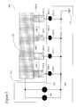
- FIG. 3shows an array of qubits with a control system according to the present invention.
- FIG. 4shows an embodiment of a control system according to the present invention that includes readout control circuitry, which is coupled to a qubit.
- FIG. 5shows an embodiment of readout circuitry of a control system according to the present invention coupled to an array of qubits.
- FIG. 6shows an embodiment of a readout and initialization circuitry of a control system according to the present invention coupled to a qubit.
- FIG. 7shows an embodiment of a readout and initialization circuitry of a control system according to the present invention coupled to a qubit.
- FIG. 8shows an array of qubits coupled to an embodiment of a control circuit according to the present invention capable of reading out and initializing the qubits.
- FIG. 9shows an embodiment of a radio frequency single electron transistor (RF-SET).
- FIG. 10shows an embodiment of a control system according to the present invention capable of entangling qubits.
- FIG. 11shows an embodiment of a control system according to the present invention capable of entangling qubits coupled to control an array of qubits.
- FIG. 12shows an embodiment of a control system according to the present invention that is coupled to qubits.
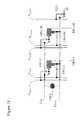
- FIG. 13shows an embodiment of a control system according to the present invention that is coupled to an array of qubits.
- FIG. 14shows an embodiment of a control system according to the present invention coupled to qubits.
- FIG. 15shows an embodiment of a control system according to the present invention coupled to an array of qubits.
- FIG. 16shows an embodiment of a control system according to the present invention coupled to a single phase qubit.
- FIG. 17shows an embodiment of a control system according to the present invention coupled to a 2-dimensional array of phase qubits.
- FIG. 18shows an embodiment of a control system according to the present invention coupled to an array of qubits, wherein the control system can entangle qubits of the array of qubits.
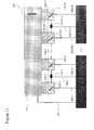
- FIG. 1shows an embodiment of a phase qubit 100 .
- phase qubit 100is shown as a permanent readout superconducting qubit in FIGS. 1-18.
- phase qubit 100can be any phase qubit including, for example, a micrometer-sized superconducting loop with several Josephson junctions and a radio-frequency superconducting quantum interference device (RF-SQUID).
- RF-SQUIDradio-frequency superconducting quantum interference device
- the material utilized in fabricating the PRSQcan be a high-T c superconductor having a pairing symmetry that contains a dominant component with non-zero angular moment, and a sub-dominant component that can have any pairing symmetry.
- the resulting qubithas the basis states ⁇ 0 , where ⁇ 0 is a quantum of phase, with respect to the phase, ⁇ , of the bulk superconductor.
- Qubit 100includes bulk superconductor 110 , a superconducting finger 112 extending across grain boundary 111 , superconducting mesoscopic island 120 , and a grounding switch 130 coupled between superconducting island 120 and ground 131 .
- Bulk superconductor 110can be fabricated from a superconducting material with a dominant pairing symmetry having a non-zero angular moment. The angle of crystal orientation of bulk superconductor 110 is related to the orientation of the superconducting order parameter A 109 and is illustrated by wave function 109 .
- mesoscopic island 120is made of a superconducting material with a dominant pairing symmetry having a non-zero angular moment.
- the crystal orientation of island 120is mismatched with respect to the crystal orientation of bulk superconductor 110 by an angle A 119 .
- the orientation of the order parameteris in part determined by the crystal orientation, thus wave function 119 is effectively rotated with respect to wave function 109 as well.
- This misalignment in the order parameters in island 120 and bulk material 110results in time-reversal symmetry breaking in the supercurrent at the grain boundary between bulk material 110 and island 120 .
- the angle of mismatch A 119 between wave function 109 and wave function 119can vary and is dependent upon the embodiment of the invention. In an embodiment where A 119 is 45°, the spontaneous current at the grain boundary is maximized.
- Single qubit operations on asymmetric qubits such as qubit 100can be performed by modulating the transport current through qubit 100 (i.e., between island 120 and bulk material 110 ). Setting the transport current I T to zero sets the effective Hamiltonian describing the quantum system of qubit 100 proportional to ⁇ circumflex over ( ⁇ ) ⁇ x , which is referred to as a Pauli matrix.
- 1>are chosen so that the state
- 1> corresponds to the vector ( 0 , 1 ), ⁇ ⁇ x[ 0 1 1 0 ] .
- This basiscan be called the Z-diagonal basis.
- the Pauli matrix ⁇ circumflex over ( ⁇ ) ⁇ xrotates one of the basis states into the other basis state (i.e., ⁇ circumflex over ( ⁇ ) ⁇ x
- 0>
- 1> and ⁇ circumflex over ( ⁇ ) ⁇ x 1>
- the effective Hamiltonian describing the qubit system of qubit 100includes a term proportional to ⁇ T (I) ⁇ circumflex over ( ⁇ ) ⁇ x , where the tunneling matrix element ⁇ T (I) can be varied over a large range depending on the Coulomb energy and the Josephson energy of the qubit system of qubit 100 .
- the tunneling amplitudeis on the order of 10 GHz.
- operations performed on qubit 100should have a larger frequency than the tunneling amplitude, or the quantum system of qubit 100 can become unpredictable. For example, if the frequency of grounding switch 130 is slower than the tunneling amplitude of qubit 130 , then the state of qubit 100 can evolve between the time the ground was applied and the actual time the ground was realized in qubit 100 .
- phase qubits with delocalized magnetic fieldslimit their overall scalability due to undesired coupling between individual qubits, as well as the more detrimental coupling with the surrounding environment. If qubit 100 is a phase qubit made out of a superconducting ring, there can be a tendency towards inductively coupling to the surrounding environment. A system involving qubits fabricated from superconducting rings, then, should be spaced apart such that the inductance with other qubits and surrounding current carrying circuitry is minimized. Some proposed embodiments of phase qubits have low inductance and therefore low inherent coupling to surrounding circuitry.
- a permanent readout superconducting qubitsuch as qubit 100 of FIG. 1, disclosed by A. Zagoskin, can provide close-spaced qubits because of the reduced undesired inductive coupling between qubits.
- Qubit 100stores state information in highly localized phases and persistent currents, thus minimizing any potential coupling effects with adjacent qubits.
- the low inductance in Qubit 100can allow adjacent qubits to be placed with closer spacing, and still allow for surrounding control system circuitry.
- FIG. 2shows qubit 100 coupled with a control system 800 .
- Control system 800can be coupled to bulk superconductor 110 , for example through line 801 , and to island 120 , for example through line 802 .
- Controller 800can provide currents through qubit 100 and can ground qubit 100 in order to read the quantum states of qubit 100 or initiate quantum states of qubit 100 .
- Controller 800can read out the state of qubit 100 by grounding qubit 100 , applying a current across qubit 100 , measuring a voltage across qubit 100 , and interpreting the quantum state of qubit 100 based on the measured voltage.
- the quantum state of qubit 100is evolving quantum mechanically, the states of qubit 100 are in a superposition of the two degenerate quantum states.
- the wavefunctioncollapses into one of the two available degenerate basis states.
- the fluxwhich defines the basis state (i.e., either the
- An embodiment of a method of reading out the state of a qubitcan include, grounding a qubit, applying a current pulse across said qubit to ground, and measuring a potential across said qubit with respect to ground.
- the potential dropcan be in the form of one or more pulses, whereby the temporal position of the pulses, with respect to the initial passing of current across the current, can be resolved.
- a potential measurementcan be made for a fixed duration of time with respect to the passing of current across the qubit. Correlation of the qubit state can then be made based on the presence or absence of a change in the potential measured across the qubit during said time period.
- the theoretical I-V characteristics of superconducting materialshave shown a range over which current flowing in the superconductor can vary, typically between ⁇ I c , where the voltage is zero. I c is thus called the critical current in the superconductor material. For values of current beyond the critical current, dynamical processes occur and the superconducting material becomes resistive. In the non-ideal case, the supercurrent range, ⁇ I c , is not associated with a zero voltage across qubit 100 but a near zero voltage, typically offset by a subgap resistance. Therefore, in order to readout a classical state of qubit 100 , a current at or less than the critical current of the system may be applied.
- the critical currentis I c1
- the critical currentis I c2 .
- the values of state dependent critical currentsare dependent upon the embodiment of qubit 100 , but by selecting an appropriate tunnel barrier height in the potential well, the values of I c1 and I c2 can be made distinct.
- the height of the tunneling barrier in the potential energy of qubit 100can be adjusted by tuning the tunneling amplitude of the qubit. This can be accomplished, for example, by tuning the capacitance of qubit 100 .
- the critical currents I c1 and I c2are already known, then by applying a bias current with a magnitude between the two critical currents, for example at (I c1 +I c2 )/2, then the quantum state of qubit 100 may be determined by measuring the resulting potential drop across qubit 100 (i.e., between island 120 and superconducting substrate 110 ). If, for example, I c1 is the lower of the two critical currents, and the quantum system of qubit 100 corresponds to the quantum state with critical current I c1 , then the applied current will exceed the critical current of the system and dynamical effects will result in a measurable voltage across qubit 100 .
- the quantum state of qubit 100corresponds to the quantum state with critical current I c2 , then the applied current will not exceed the critical current of the system, and measuring the potential drop across qubit 100 will only indicate a small voltage associated with the subgap resistance.
- controller 800can readout the quantum state of qubit 100 by grounding qubit 100 (i.e., coupling island 120 to ground), applying a bias current across qubit 100 , the bias current being of a magnitude between the critical currents associated with the quantum states of qubit 100 , and measuring the potential drop across qubit 100 .
- Qubit control system 800 of FIG. 2can include circuits for reading out the quantum state of qubit 100 .
- Qubit control system 800can have one control branch 801 coupled to bulk superconductor 110 , and a second control branch 802 coupled to island 120 of qubit 100 , control system 800 , then can perform a readout procedure by grounding qubit 100 through control line 802 , applying a current to bulk superconductor 110 through control branch 801 , and measuring the potential drop across control branch 801 and the qubit branch 802 .
- the currentis a supercurrent of Cooper pairs.
- control system 800measures the voltage across qubit 100 .
- Control system 800interprets the measured potential drop as indicating one of the possible states of qubit 100 .
- Control system 800can then communicate the measured quantum state of qubit 100 to another system (not shown) that interfaces with qubit control system 800 .
- Control system 800can provide an automatic readout method in an integrated circuit manner. Furthermore, control system 800 easily generalizes to an array of qubits, whereby a readout method could be applied to each of the qubits in the array of qubits in succession. Qubit control system 800 provides an interface which further helps to isolate a qubit system that includes qubit 100 from the surrounding environment. An external system could, then, interact with control system 800 , and not directly with qubit 100 .
- control system 800can be calibrated.
- the state specific critical currents of qubit 100can be first determined as a calibration of the bias current to be applied during the readout of the quantum state of qubit 100 .
- the readout procedure discussed abovecan then be performed where the applied bias current is between the bounding critical currents corresponding to the two quantum states. Measuring the potential across qubit 100 would then indicate which state is present in qubit 100 .
- the appropriate bias currentcan be stored by a system that interfaces with control system 800 .
- FIG. 3shows an embodiment of a qubit array 300 with control system 800 coupled to qubit array 300 .
- Qubit array 300includes qubitss 100 - 1 through 100 -N.
- a single control branch 801is coupled to superconducting substrate 110 , which is common to qubits 100 - 1 through 100 -N.
- Qubit branches 802 - 1 through 802 -Nare coupled to islands 120 - 1 through 120 -N, respectively.
- Controller 800can perform readout procedures as described above on each of qubits 100 - 1 through 100 -N.
- the qubit being readis grounded while the remaining ones of qubits 100 - 1 through 100 -N are not grounded.
- the potential drop taken across control branch 801 and the grounded qubit branchcan be measured and interpreted by control system 800 in order to determine the quantum state of the qubit being read.
- a simultaneous readout of the quantum register represented by qubit array 300is performed.
- each of qubits 100 - 1 through 100 -N in qubit system 300can be grounded simultaneously and readout in turn.
- only one of qubits 100 - 1 through 100 -N to be read outis grounded while the remaining ones of qubits 100 - 1 through 100 -N in qubit system 300 continue to evolve quantum mechanically.
- the evolutioncan be predicted and the exact time at which the one of qubits 100 - 1 through 100 -N next to be read will again be in the required state can be determined.
- a method for reading out the state of a quantum register system 300includes a timing mechanism, whereby each consecutive qubit of qubits 100 - 1 through 100 -N will be read at corresponding intervals that correlate with a return to the required state of each of qubits 100 - 1 through 100 -N.
- FIG. 4shows an embodiment of control system 800 coupled to qubit 100 .
- Control system 800includes a grounding switch 130 , a current source 140 , and a voltmeter 150 .
- Grounding switch 130can couple island 120 to ground.
- Current source 140is coupled to provide current to bulk superconductor 110 .
- Voltmeter 150is coupled to measure the potential drop between ground and bulk superconductor 110 .
- grounding switch 130If grounding switch 130 is closed, the circuit that includes grounding switch, current source 140 , bulk superconductor 110 , and mesoscopic island 120 is completed and current will flow across qubit 100 . Furthermore, voltmeter 150 is coupled in parallel with qubit 100 between bulk superconductor 110 and ground 131 such that when grounding switch 130 is closed, voltmeter 150 measures the potential across qubit 100 .
- switch 130can be a single electron transistor or parity key that can couple island 120 to ground.
- control circuit 800can open or close the grounding connection.
- SETsingle electron transistor
- the state specific critical current values generated by current source 140 for qubit 100is calibrated and used to characterize the magnitude of the bias current.
- the bias current for each of the qubits in the qubit systemis determined and stored in a system that interfaces with control system 800 .
- voltmeter 150can be a radio-frequency single electron transistor, capable of measuring a magnitude on the order of microvolts on a time-scale of picoseconds. See i.e., R. J. Schoelkopf, P. Wahlgren, A. A. Kozhevnikov, P. Delsing, D. E. Prober “The Radio-Frequency Single-Electron Transistor (RF-SET): A Fast and Ultrasensitive Electrometer”, Science, 280, 1238 (May 1998), herein incorporated by reference in its entirety.
- RF-SETRadio-Frequency Single-Electron Transistor
- a readout method using the embodiment of control system 800 shown in FIG. 4includes grounding qubit 100 through grounding switch 130 , applying a bias current through current source 140 , measuring the potential drop across qubit 100 in voltmeter 150 , and interpreting the measured potential drop to determine the quantum state of qubit 100 .
- voltmeter 150may by calibrated to output directly the measured quantum state of qubit 100 .
- other portions of control system 800are calibrated to receive the voltage measurement from voltmeter 150 and determine the quantum state of qubit 100 .
- Qubit 120can be grounded to ground 131 through grounding switch 130 .
- the current source 140is coupled in series with qubit 100 and ground 131
- voltmeter 150is coupled in parallel with qubit 100 .
- switch 130When switch 130 is closed, grounding island 120 , the wavefunction of the supercurrent collapses into one of the ground states ⁇ 0 , which has a definite magnetic moment.
- island 120grounded and the quantum state of qubit 100 fixed, a current is applied through qubit 100 by current source 140 . Current travels through bulk superconductor 110 and through island 120 to ground 131 .
- Voltmeter 150measures the voltage and the detected voltage peak is interpreted to determine the state of the qubit.
- the bias current generated by current source 140is between the quantum state associated critical currents of the qubit.
- FIG. 5shows an example of an array of qubits 300 coupled to an embodiment of controller 800 .
- Each of qubits 100 - 1 through 100 -N in qubit system array of qubits 300is coupled to a grounding switch 130 - 1 through 130 -N, respectively, by which each of qubits 100 - 1 through 100 -N can be selectively coupled to ground 131 when controller system 800 closes switch 130 - 1 through 130 -N, respectively.
- current source 140is coupled between bulk superconductor 110 and ground 131 .
- Voltmeter 150is coupled in parallel with qubits 100 - 1 through 100 -N between bulk superconductor 110 and ground 131 .
- control system 800grounds island 120 - 1 by closing switch 130 - 1 . Switches 130 - 2 through 130 -N are left open. Control system 800 can then apply, through current source 140 , a bias current through qubit 100 - 1 and the potential drop across qubit 100 - 1 can be measured by voltmeter 150 . The quantum state of qubit 100 - 1 is determined by the characteristic voltage measured by voltmeter 150 . The readout method can then be repeated, in turn, for all of qubits 100 - 1 through 100 -N.
- control system 800 and all coupling leadsare fabricated from a high-T c superconducting material such as YBa 2 Cu 3 O 7 ⁇ x , where x has values between about 0 and about 0.6.
- a high-T c superconducting materialsuch as YBa 2 Cu 3 O 7 ⁇ x , where x has values between about 0 and about 0.6.
- Other superconducting materialssuch as Bi 2 Sr 2 Ca n ⁇ 1 Cu n O 2n+4 , Ti 2 Ba 2 CuO 6+x , and HgBa 2 CuO 4 , are examples of d-wave superconductors with a pairing symmetry having a non-zero angular moment, which can also be utilized to fabricate control system 800 .
- low temperature superconductor Sr 2 RuO 4 or heavy fermion material CeIrIn 5can be utilized to fabricate control system 800 .
- qubit system 300operates at a temperature of around 1K.
- control system 800also initializes the quantum states of qubits 100 - 1 through 100 -N in qubit system 300 .
- a method for initializing the state of a qubit 100includes driving a current across the qubit in a specific direction and ramping the current down to zero.
- the bistability of the ground state in qubit 100occurs when the bias current through qubit 100 is reduced to zero, where the classical quantum states of qubit 100 corresponds to ⁇ 0 .
- a first statecan be selected, and by driving a current across qubit 100 in the reverse direction a second state can be selected.
- control system 800initializes qubit 100 by maintaining a small magnitude current directionally across qubit 100 for a sufficient duration of time.
- the current from current source 140effectively biases the potential energy in qubit 100 , removing the degeneracy in the classical quantum states. Given a sufficient period of time, the quantum state of qubit 100 will transition into the more energetically favorable state, which is determined by the direction of the applied bias current from current source 140 .
- FIG. 6shows an embodiment of control system 800 coupled to qubit 100 that can initialize a quantum state of qubit 100 .
- Control system 800 of FIG. 6includes a bi-directional current source 140 and a grounding switch 130 , which can couple island 120 to ground 131 .
- Voltmeter 140 in FIG. 6can be included to facilitate readout procedures of qubit 100 .
- An initialization methodincludes closing switch 130 to ground qubit 100 , applying current from current source 140 to qubit 100 at some magnitude I b , and then ramping the current from source 140 from magnitude I b back to zero.
- control circuit 800applies a positive current I b to initialize a first state, and applies a negative current I b to initialize a second state.
- an initialization procedureincludes closing switch 130 , which grounds island 120 of qubit 100 , and applying a bias current through qubit 100 from current source 140 for a duration of time long enough for the quantum states of qubit 100 to transition, for example by tunneling, into the selected initial state.
- the duration of timeis dependent on the tunneling rate of the qubit system, and in some embodiments is on the order of the tunneling amplitude of qubit 100 so that the quantum system of qubit 100 relaxes into the selected state.
- FIG. 7shows an embodiment of a current source 140 which is bi-directional.
- Current source 140includes a first current source 141 and a second current source 142 .
- Current source 141is coupled in series with a switch 143 and current source 142 is coupled in series with a switch 144 .
- the combination of current source 141 and switch 143is coupled in parallel with current source 142 and switch 144 , which is coupled between superconducting substrate 110 and ground 131 .
- Control system 800can, then, select current source 141 , which provides current in a first direction, by closing switch 143 and opening switch 144 .
- current source 800can select current source 142 , which provides current in a second direction opposite the first direction, by closing switch 144 and opening switch 143 .
- each of switch 141 and 143can be a SET.
- FIG. 8shows an embodiment of control system 800 as described with FIG. 7 above coupled to a qubit system 300 .
- Qubit system 300includes qubits 100 - 1 through 100 -N.
- control system 800can initialize each of qubits 100 - 1 through 100 -N in turn, where one of qubits 100 - 1 through 100 -N to be initialized is selected by closing the respective one of switches 130 - 1 through 130 -N, grounding the selected one of qubits 100 - 1 through 100 -N and applying current across the one of qubits 100 - 1 through 100 -N being initialized.
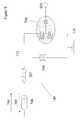
- FIG. 9demonstrates an embodiment of voltmeter 140 which can be utilized with controller 800 .
- Voltmeter 140can be a radio-frequency single electron transistor electrometer such as that described in, for example, A. N. Korotkov and M. A. Paalanen, “Charge Sensitivity of Radio-Frequency Single Electron Transistor, Appl. Phys. Lett. 74, 26 (1999), which is herein incorporated by reference in its entirety.
- the operation and behaviour of SETsis well known, and is described in detail in P Joyez et al., “Observation of Parity-Induced Supression of Josephson Tunneling in the Superconducting Single Electron Transistor,” Physical Review Letters, Vol. 72, No. 15, 11 Apr. 1994, which is herein incorporated by reference in its entirety.
- the RF-SET voltmeter 140is comprised of a SET 709 , a tank circuit 712 , and a port for applying and detecting a signal 706 .
- the single-electron transistor (SET) 709can be made of any superconducting material, for example niobium, aluminum, lead, tin, and any high-temperature superconducting cuprate. A description of the operation and manufacture of single electron transistors is described in P. Joyez et al., “Observation of Parity-Induced Suppression of Josephson Tunneling in the Superconducting Single Electron Transistor”, Physical Review Letters, Vol. 72, No. 15, 11 Apr. 1994, and R. J. Schoelkopf, P. Wahlgren, A. A.
- SET 709is placed in a high quality factor tank circuit 712 tuned to resonance.
- Tank circuit 712includes inductor 707 and capacitor 708 .
- Capacitor 708is coupled in parallel with SET 709 .
- a third terminal of SET 709is coupled to electrode 801 , which in control system 800 is coupled to superconducting substrate 110 .
- a radio-frequency or microwave signal 704is introduced into circuit 712 .
- the reflected signal 705is a function of the conductance of SET 709 . Analysis of reflected signal 705 using established techniques allows measurement of the voltage difference between electrode 710 and ground 131 .
- readout of the quantum state of qubit 100may be done via the use of a single electron transistor (SET) according to known procedures, described, for example, by Makhlin Y, Schoen G, and Shnirman A, “Quantum state engineering with Josephson junction devices,” arXiv, cond-mat/0011269, 15 Nov. 2000, which is hereby included by reference in its entirety.
- An embodiment of a SETis shown as SET 709 of FIG. 9 .
- SET 709may be coupled to three devices (e.g., terminals 131 , 801 and 712 ).
- An electron or Cooper paircan tunnel onto SET 709 when SET 709 is uncharged.
- SET 709is small enough that once an electron or Cooper pair tunnels onto SET 709 , the charging of SET 709 electrically repels and prevents further tunneling onto SET 709 .
- a terminal 801 associated with SET 709can change the voltage of SET 709 and de-tune tank circuit 712 , changing the characteristics of the reflected wave 705 .
- control system 800can entangle quantum states between two qubits, qubits 100 - 1 and 100 - 2 of qubit pair 1000 .
- Control system 800 of FIG. 10further controls an entanglement switch 155 through a control line 820 .
- Entanglement of qubitsoccurs during free evolution of the quantum states of qubits 100 - 1 and 100 - 2 .
- an entanglement operationallows the wavefunctions of the quantum states of each of qubits 100 - 1 and 100 - 2 to overlap, thus mixing information about the state of each of qubits 100 - 1 and 100 - 2 .
- control system 800can entangle the quantum states of qubits 100 - 1 and 100 - 2 by directly coupling islands 120 - 1 and 120 - 2 of qubits 100 - 1 and 100 - 2 , respectively, together through an entanglement switch 155 and controlling the state of switch 155 .
- switch 155When switch 155 is closed, a supercurrent can pass between island 120 - 1 and 120 - 2 .
- Control system 800is capable of switching switch 155 , controlling the coupling between qubits 100 - 1 and 100 - 2 , on and off as required for implementation of a quantum algorithm.
- entanglement switch 155allows the coherent passing of cooper pairs when closed, while effectively severing the link between qubits 100 - 1 and 100 - 2 when open.
- the switching rate of entanglement switch 155is on the order of the largest possible tunneling amplitude in qubits 100 - 1 and 100 - 2 , such that entanglement switch 155 is fast when compared to the time scales of quantum state transitions in qubits 100 - 1 and 100 - 2 .
- controller 800couples qubits 100 - 1 and 100 - 2 for a unit duration of time, wherein the unit duration is dependent upon the embodiment of qubits 100 - 1 and 100 - 2 .
- the unit durationcan be at least on the order of the tunneling amplitude of qubit system 1000 . Where a longer coupling duration is required by a computing algorithm, multiple unit duration entanglements can be combined.
- FIG. 11shows an embodiment of the invention with a qubit array 300 coupled to a control system 800 where control system 800 can entangle the quantum states of adjacent ones of qubits 100 - 1 through 100 -N.
- Adjacent pairs of qubits 100 - 1 through 100 -Nare coupled through switches 155 - 1 through 155 -(N- 1 ).
- Qubits 100 - 1 and 100 - 2are coupled through switch 155 - 1 , for example, while qubits 100 -(N- 1 ) and 100 -N are coupled through switch 155 -(N- 1 ).
- Controller 800is coupled to each of switches 155 - 1 through 155 -(N- 1 ) so that controller 800 can entangle quantum states between adjacent ones of qubits 100 - 1 through 100 -N in response to algorithm program instructions.
- FIG. 12shows an embodiment of the invention where control system 800 can initialize qubits 100 - 1 and 100 - 2 of qubit pair 1000 , can readout qubits 100 - 1 and 100 - 2 , and can entangle qubits 100 - 1 and 100 - 2 as discussed above.
- Control system 800includes a bi-directional current source 140 coupled across qubits 100 - 1 and 100 - 2 , a voltmeter 150 coupled across qubits 100 - 1 and 100 - 2 , grounding switches 130 - 1 and 130 - 2 coupled between islands 120 - 1 and 120 - 2 , respectively, and ground 131 , and entanglement voltage source 160 coupled to entanglement switch 155 to control the entanglement between qubits 100 - 1 and 100 - 2 .
- entanglement switch 155is a SET or parity key, and voltage source 160 turns entanglement switch 155 to an open state or a closed state.
- Control system 800can entangle the quantum states of qubits 100 - 1 and 100 - 2 by applying a voltage V g with voltage source 160 to entanglement switch 155 . Entanglement switch 155 then closes and allows cooper pairs to flow between qubits 100 - 1 and 100 - 2 , thus entangling the quantum states of qubits 100 - 1 and 100 - 2 .
- grounding switches 130are open so that the qubits 100 - 1 and 100 - 2 are isolated from the environment and are freely evolving quantum mechanically.
- control system 800 in FIG. 12can readout the quantum state of qubits 100 - 1 and 100 - 2 by opening entanglement switch 155 , grounding one of islands 120 - 1 and 120 - 2 through grounding switches 130 - 1 and 130 - 2 , and applying a current from current source 140 while monitoring the voltage across the one of qubits 100 - 1 and 100 - 2 being read. Additionally, controller 800 in FIG.
- FIG. 13shows a qubit array (register) 300 coupled to control system 800 .
- Control system 800can perform readout operations on each of qubits 100 - 1 through 100 -N, can initialize each of qubits 100 - 1 through 100 -N, and can entangle adjacent pairs of qubits 100 - 1 through 100 -N.
- Adjacent ones of qubits 100 - 1 through 100 -Nare coupled through entanglement switches 155 - 1 through 155 -(N- 1 ), where the state of each entanglement switch 155 - 1 through 155 -(N- 1 ) can be modulated by voltage sources 160 - 1 through 160 -(N- 1 ), respectively.
- Controller 800entangles adjacent pairs of qubits 100 - 1 through 100 -N in response to algorithm instructions which can be communicated to controller 800 .
- control system 800 of FIG. 13includes a current source 140 , a voltmeter 150 , grounding switches 130 - 1 through 130 -N, and a ground 131 that, as discussed above, allow control system 800 to read out the quantum states of qubits 100 - 1 through 100 -N and initialize the quantum states of qubits 100 - 1 through 100 -N. In this manner, control system 800 provides all of the operations for performing quantum computation algorithms.
- FIG. 14shows another embodiment of a pair of qubits 1000 coupled to a control system 800 capable of reading out the quantum states of qubits 100 - 1 and 100 - 2 , initiating quantum states in qubits 100 - 1 and 100 - 2 , and entangling quantum states in qubits 100 - 1 and 100 - 2 .
- Control system 800includes switch 132 coupled between ground 131 and switches 130 - 1 and 130 - 2 .
- Control system 800can entangle the quantum states of qubits 100 - 1 and 100 - 2 by closing both switches 130 - 1 and 130 - 2 and opening switch 132 so that switches 130 - 1 and 130 - 2 do not ground islands 120 - 1 and 120 - 2 , respectively.
- a switch 145can also be included between parallel coupled current source 140 and voltmeter 150 and superconducting substrate 110 . Qubits 100 - 1 and 100 - 2 , then, can be further decoupled from influences outside of qubits 100 - 1 and 100 - 2 .
- one of qubits 100 - 1 and 100 - 2can be read out by closing switch 132 and switch 145 , closing the one of switches 130 - 1 or 130 - 2 that corresponds to the qubit being read, applying a current from current source 140 , and measuring the voltage with voltmeter 150 .
- One of qubits 100 - 1 and 100 - 2can be initiated by closing switch 132 and switch 145 , closing one of switches 130 - 1 or 130 - 2 depending on which of qubits 100 - 1 or 100 - 2 is being initiated, and applying a current across the one of qubits 100 - 1 and 100 - 2 from source 140 .
- FIG. 15shows another embodiment of a qubit array 300 coupled to control system 800 , where control system 800 can perform read out, initialization, and entanglement operations on qubits 100 - 1 through 100 -N.
- Each of qubits 100 - 1 through 100 -Nis coupled through switches 130 - 1 through 130 -N, respectively, to ground through switch 132 .
- Control system 800can ground each of islands 120 - 1 through 120 -N by closing switches 130 - 1 through 130 -N, respectively, and closing switch 132 .
- Control system 800can entangle the states of adjacent ones of qubits 100 - 1 through 100 -N by closing the corresponding ones of switches 130 - 1 through 130 -N and opening switch 132 . Additionally, control system 800 as shown in FIG.
- Qubit 15is not limited to entangling quantum states between adjacent ones of qubits 100 - 1 through 100 -N.
- Qubits 120 - 2 and 120 -(N- 1 )can be entangled by closing switches 130 - 2 and 130 -(N- 1 ) while opening switch 132 .
- any number of qubitscan be entangled by closing the respective ones of switches 130 - 1 through 130 -N and opening switch 132 .
- FIG. 16shows a single qubit system 600 that includes a qubit 100 , a qubit switch 145 modulated by a voltage V 145 , a grounding switch 130 modulated by a voltage V 130 , a current line I 140 coupled to qubit 100 through qubit switch 145 , a ground 131 coupled to qubit 100 through grounding switch 130 , and a voltmeter 150 coupled to measure the potential drop between the current line I 140 and ground 131 .
- An embodiment of a method for initializing the state of qubit 100 in system 600can include applying voltages V 145 and V 130 to qubit switch 145 and grounding switch 130 , respectively, and applying a current I 140 . The direction of the applied current can determine the selected basis state of qubit 100 .
- An embodiment of a method for reading out the state of qubit 100can include applying voltages V 145 and V 130 to qubit switch 145 and ground switch 130 , respectively, thus grounding qubit 100 , applying a current to current line I 140 , measuring the potential drop between current line I 140 and ground 131 , and interpreting the state of qubit 100 based on the measured potential drop.
- FIG. 17shows a two-dimensional representation of a grid of qubits that includes qubits 100 - 1 , 1 , through 100 -N,M.
- Qubits 100 - 1 , 1 through qubits 100 -N,Mare coupled through switches 145 - 1 , 1 through 145 -N,M, respectively by row, to currents I 140-1 through I 140-N .
- qubits 100 - 1 , 1 through qubits 100 -N,Mare coupled through switches 130 - 1 , 1 through 130 -N,M, respectively by row, to ground 131 - 1 through 131 -N.
- Switches 145 - 1 , 1 through 145 -N,Mare coupled, by columns, to control voltages V 145-1 through V 145-M . Further, switches 130 - 1 , 1 through 130 -N,M are coupled, by columns, to control voltages V 130-1 through V 130-M . Further, voltmeters 150 - 1 through 150 -N measure the potential drops between I 140-1 through I 140-N and ground 131 - 1 to 131 -N, respectively. With this notation, for example, qubit 100 -i,j refers to the ith row and the jth column.
- qubits 100 - 1 , 1 through 100 -N,Mcan be initialized by initializing each successive column of qubits simultaneously, and progressing across the columns. For example, first a voltage can be applied to the voltage lines V 145-1 and V 130-1 , thus closing the respective qubit switches and grounding switches for every qubit in the first column. Secondly, a current can be applied to each of the current lines I 140-1 through I 140-N simultaneously, such that the direction of the current in the respective current line determines the basis state to be initialized. The process can then be repeated for the remaining columns in the grid, thus requiring a total of M steps to initialize the entire qubit system.
- An embodiment of a method for reading out the state of the grid qubit system, qubits 100 - 1 , 1 through 100 -N,Mcan include grounding the entire system by closing each of switches 100 - 1 , 1 through 100 -N,M, applying a voltage to one column of qubit switchs 145 - 1 , 1 through 145 -N,M of a column of qubits to be read, applying a current to the respective current line of said first qubit, measuring the potential drop between the respective current line and grounding lines, and interpreting the state of the qubit that is being read.
- qubits 100 - 1 , 1 through 100 -N,M in the qubit systemcan be completely isolated from the surroundings by opening all of switches 145 - 1 , 1 through 145 -N,M and 130 - 1 , 1 through 130 -N,M.
- an aspect of quantum computingcan include entanglement of qubit states.
- An embodiment of the inventioncan provide a method for entangling qubits in a qubit system, wherein the qubit system can have a 2-dimensional grid layout. If the ground line includes a line grounding switch, then the line can be used as a means of entangling the state any two qubits in a row when the ground is disconnected from the line.
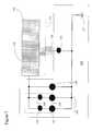
- FIG. 18shows an embodiment of the invention, wherein the grounding line 131 - 1 includes a line grounding switch 132 - 1 , modulated by the voltage V G-132 .
- An embodiment of a method for entangling qubitscan include opening line grounding switch 132 - 1 in the row, such that a qubit connected to the grounding line 131 - 1 remains isolated from ground. Modulation of grounding switch 132 - 1 can be controlled by a voltage line V G-132 .
- the voltage linemodulates the line grounding switches for all rows.
- each of the line grounding switchescan be modulated independently of the other rows in the system. In such an embodiment, each qubit could be grounded independently of all other qubits in the system, thus allowing the readout and initialization of individual qubits without any disruption to calculation.
Landscapes
- Engineering & Computer Science (AREA)
- Theoretical Computer Science (AREA)
- Physics & Mathematics (AREA)
- General Physics & Mathematics (AREA)
- Nanotechnology (AREA)
- Chemical & Material Sciences (AREA)
- Mathematical Physics (AREA)
- Data Mining & Analysis (AREA)
- Software Systems (AREA)
- Mathematical Optimization (AREA)
- Pure & Applied Mathematics (AREA)
- Computing Systems (AREA)
- General Engineering & Computer Science (AREA)
- Evolutionary Computation (AREA)
- Mathematical Analysis (AREA)
- Condensed Matter Physics & Semiconductors (AREA)
- Computational Mathematics (AREA)
- Crystallography & Structural Chemistry (AREA)
- Artificial Intelligence (AREA)
- Superconductor Devices And Manufacturing Methods Thereof (AREA)
- Crystals, And After-Treatments Of Crystals (AREA)
Abstract
Description

Claims (43)
Priority Applications (11)
| Application Number | Priority Date | Filing Date | Title |
|---|---|---|---|
| US09/872,495US6803599B2 (en) | 2001-06-01 | 2001-06-01 | Quantum processing system for a superconducting phase qubit |
| CA002448682ACA2448682A1 (en) | 2001-06-01 | 2002-05-29 | Quantum processing system for a superconducting phase qubit |
| EP05077051AEP1669911A3 (en) | 2001-06-01 | 2002-05-29 | Quantum processing system for a superconducting phase qubit |
| DE60212967TDE60212967T2 (en) | 2001-06-01 | 2002-05-29 | QUANTUM PROCESSING SYSTEM FOR A SUPERCONDUCTIVE PHASE QUBIT |
| PCT/CA2002/000787WO2002097725A2 (en) | 2001-06-01 | 2002-05-29 | Quantum processing system for a superconducting phase qubit |
| JP2003500831AJP2004533061A (en) | 2001-06-01 | 2002-05-29 | Quantum processing system for superconducting phase qubit |
| AT02732272TATE332542T1 (en) | 2001-06-01 | 2002-05-29 | QUANTUM PROCESSING SYSTEM FOR A SUPERCONDUCTING PHASE QUBIT |
| AU2002304920AAU2002304920A1 (en) | 2001-06-01 | 2002-05-29 | Quantum processing system for a superconducting phase qubit |
| EP02732272AEP1395947B1 (en) | 2001-06-01 | 2002-05-29 | Quantum processing system for a superconducting phase qubit |
| US10/791,617US6936841B2 (en) | 2001-06-01 | 2004-03-02 | Methods for controlling qubits |
| US10/791,579US20040167036A1 (en) | 2001-06-01 | 2004-03-02 | Systems and methods for entangling qubits |
Applications Claiming Priority (1)
| Application Number | Priority Date | Filing Date | Title |
|---|---|---|---|
| US09/872,495US6803599B2 (en) | 2001-06-01 | 2001-06-01 | Quantum processing system for a superconducting phase qubit |
Related Child Applications (2)
| Application Number | Title | Priority Date | Filing Date |
|---|---|---|---|
| US10/791,579ContinuationUS20040167036A1 (en) | 2001-06-01 | 2004-03-02 | Systems and methods for entangling qubits |
| US10/791,617ContinuationUS6936841B2 (en) | 2001-06-01 | 2004-03-02 | Methods for controlling qubits |
Publications (2)
| Publication Number | Publication Date |
|---|---|
| US20020188578A1 US20020188578A1 (en) | 2002-12-12 |
| US6803599B2true US6803599B2 (en) | 2004-10-12 |
Family
ID=25359679
Family Applications (3)
| Application Number | Title | Priority Date | Filing Date |
|---|---|---|---|
| US09/872,495Expired - LifetimeUS6803599B2 (en) | 2001-06-01 | 2001-06-01 | Quantum processing system for a superconducting phase qubit |
| US10/791,579AbandonedUS20040167036A1 (en) | 2001-06-01 | 2004-03-02 | Systems and methods for entangling qubits |
| US10/791,617Expired - LifetimeUS6936841B2 (en) | 2001-06-01 | 2004-03-02 | Methods for controlling qubits |
Family Applications After (2)
| Application Number | Title | Priority Date | Filing Date |
|---|---|---|---|
| US10/791,579AbandonedUS20040167036A1 (en) | 2001-06-01 | 2004-03-02 | Systems and methods for entangling qubits |
| US10/791,617Expired - LifetimeUS6936841B2 (en) | 2001-06-01 | 2004-03-02 | Methods for controlling qubits |
Country Status (8)
| Country | Link |
|---|---|
| US (3) | US6803599B2 (en) |
| EP (2) | EP1395947B1 (en) |
| JP (1) | JP2004533061A (en) |
| AT (1) | ATE332542T1 (en) |
| AU (1) | AU2002304920A1 (en) |
| CA (1) | CA2448682A1 (en) |
| DE (1) | DE60212967T2 (en) |
| WO (1) | WO2002097725A2 (en) |
Cited By (41)
| Publication number | Priority date | Publication date | Assignee | Title |
|---|---|---|---|---|
| US20030071258A1 (en)* | 2001-08-29 | 2003-04-17 | Zagoskin Alexandre M. | Superconducting low inductance qubit |
| US20040140537A1 (en)* | 2002-04-15 | 2004-07-22 | D-Wave Systems, Inc. | Extra-substrate control system |
| US20040165454A1 (en)* | 2002-11-25 | 2004-08-26 | Amin Mohammad H. S. | Quantum logic using three energy levels |
| US20040167036A1 (en)* | 2001-06-01 | 2004-08-26 | D-Wave Systems, Inc. | Systems and methods for entangling qubits |
| US20050273306A1 (en)* | 2001-12-22 | 2005-12-08 | Hilton Jeremy P | Hybrid classical-quantum computer architecture for molecular modeling |
| WO2007085074A1 (en)* | 2006-01-27 | 2007-08-02 | D-Wave Systems, Inc. | Methods of adiabatic quantum computation |
| US20070239366A1 (en)* | 2004-06-05 | 2007-10-11 | Hilton Jeremy P | Hybrid classical-quantum computer architecture for molecular modeling |
| US20080086438A1 (en)* | 2004-03-29 | 2008-04-10 | Amin Mohammad H S | Adiabatic quantum computation with superconducting qubits |
| US7588550B2 (en) | 2003-03-14 | 2009-09-15 | The Trustees Of Columbia University In The City Of New York | Systems and methods of blood-based therapies having a microfluidic membraneless exchange device |
| US7727399B2 (en) | 2006-05-22 | 2010-06-01 | The Trustees Of Columbia University In The City Of New York | Systems and methods of microfluidic membraneless exchange using filtration of extraction outlet streams |
| US20100281885A1 (en)* | 2007-12-28 | 2010-11-11 | D-Wave Systems Inc. | Systems, methods, and apparatus for cryogenic refrigeration |
| US7850633B2 (en) | 2003-03-14 | 2010-12-14 | The Trustees Of Columbia University In The City Of New York | Systems and methods of blood-based therapies having a microfluidic membraneless exchange device |
| US7930152B2 (en) | 2006-07-14 | 2011-04-19 | Colorado School Of Mines | Method for signal and image processing with lattice gas processes |
| US8496606B2 (en) | 2008-02-04 | 2013-07-30 | The Trustees Of Columbia University In The City Of New York | Fluid separation devices, systems and methods |
| US9136457B2 (en) | 2006-09-20 | 2015-09-15 | Hypres, Inc. | Double-masking technique for increasing fabrication yield in superconducting electronics |
| US9473124B1 (en) | 2009-10-12 | 2016-10-18 | Hypres, Inc. | Low-power biasing networks for superconducting integrated circuits |
| US9520180B1 (en) | 2014-03-11 | 2016-12-13 | Hypres, Inc. | System and method for cryogenic hybrid technology computing and memory |
| US10148285B1 (en) | 2012-07-25 | 2018-12-04 | Erich Schmitt | Abstraction and de-abstraction of a digital data stream |
| US10222416B1 (en) | 2015-04-14 | 2019-03-05 | Hypres, Inc. | System and method for array diagnostics in superconducting integrated circuit |
| US10378803B2 (en) | 2014-08-08 | 2019-08-13 | D-Wave Systems Inc. | Systems and methods for electrostatic trapping of contaminants in cryogenic refrigeration systems |
| US10606720B2 (en)* | 2016-06-09 | 2020-03-31 | Google Llc | Automatic qubit calibration |
| US10795858B1 (en) | 2014-02-18 | 2020-10-06 | Erich Schmitt | Universal abstraction and de-abstraction of a digital data stream |
| US10885459B2 (en) | 2007-04-05 | 2021-01-05 | D-Wave Systems Inc. | Physical realizations of a universal adiabatic quantum computer |
| US10929294B2 (en) | 2017-03-01 | 2021-02-23 | QC Ware Corp. | Using caching techniques to improve graph embedding performance |
| US11423115B2 (en) | 2014-03-12 | 2022-08-23 | D-Wave Systems Inc. | Systems and methods for removing unwanted interactions in quantum devices |
| US20220318661A1 (en)* | 2019-07-31 | 2022-10-06 | Quantum Technologies UG (haftungsbeschränkt) | Method and device for addressing qubits, and method for producing the device |
| US11494683B2 (en) | 2017-12-20 | 2022-11-08 | D-Wave Systems Inc. | Systems and methods for coupling qubits in a quantum processor |
| US11526463B2 (en) | 2004-12-23 | 2022-12-13 | D-Wave Systems Inc. | Analog processor comprising quantum devices |
| US11790259B2 (en) | 2019-09-06 | 2023-10-17 | D-Wave Systems Inc. | Systems and methods for tuning capacitance in quantum devices |
| US11809839B2 (en) | 2022-01-18 | 2023-11-07 | Robert Lyden | Computer language and code for application development and electronic and optical communication |
| US11856871B2 (en) | 2018-11-13 | 2023-12-26 | D-Wave Systems Inc. | Quantum processors |
| US11930721B2 (en) | 2012-03-08 | 2024-03-12 | 1372934 B.C. Ltd. | Systems and methods for fabrication of superconducting integrated circuits |
| US11957065B2 (en) | 2017-02-01 | 2024-04-09 | 1372934 B.C. Ltd. | Systems and methods for fabrication of superconducting integrated circuits |
| US12087503B2 (en) | 2021-06-11 | 2024-09-10 | SeeQC, Inc. | System and method of flux bias for superconducting quantum circuits |
| US12102017B2 (en) | 2019-02-15 | 2024-09-24 | D-Wave Systems Inc. | Kinetic inductance for couplers and compact qubits |
| US12224750B2 (en) | 2021-09-03 | 2025-02-11 | 1372934 B.C. Ltd. | Topologically protected qubits, processors with topologically protected qubits, and methods for use of topologically protected qubits |
| US12301225B2 (en) | 2021-07-23 | 2025-05-13 | 1372934 B.C. Ltd. | Systems and methods for tuning capacitance in quantum devices |
| US12317757B2 (en) | 2018-10-11 | 2025-05-27 | SeeQC, Inc. | System and method for superconducting multi-chip module |
| US12367412B2 (en) | 2019-12-05 | 2025-07-22 | 1372934 B.C. Ltd. | Systems and methods for fabricating flux trap mitigating superconducting integrated circuits |
| US12376501B2 (en) | 2020-05-11 | 2025-07-29 | 1372934 B.C. Ltd. | Kinetic inductance devices, methods for fabricating kinetic inductance devices, and articles employing the same |
| US12392823B2 (en) | 2021-11-05 | 2025-08-19 | D-Wave Systems Inc. | Systems and methods for on-chip noise measurements |
Families Citing this family (67)
| Publication number | Priority date | Publication date | Assignee | Title |
|---|---|---|---|---|
| WO2003019683A2 (en) | 2001-08-29 | 2003-03-06 | D-Wave Systems, Inc. | Trilayer heterostructure josephson junctions |
| US6614047B2 (en)* | 2001-12-17 | 2003-09-02 | D-Wave Systems, Inc. | Finger squid qubit device |
| US6791109B2 (en)* | 2001-12-17 | 2004-09-14 | D-Wave Systems, Inc. | Finger SQUID qubit device |
| US7002174B2 (en)* | 2001-12-18 | 2006-02-21 | D-Wave Systems, Inc. | Characterization and measurement of superconducting structures |
| US20040016918A1 (en)* | 2001-12-18 | 2004-01-29 | Amin Mohammad H. S. | System and method for controlling superconducting qubits |
| US20030121028A1 (en)* | 2001-12-22 | 2003-06-26 | Michael Coury | Quantum computing integrated development environment |
| US6605822B1 (en) | 2002-03-16 | 2003-08-12 | D-Wave Systems, Inc. | Quantum phase-charge coupled device |
| US7332738B2 (en)* | 2002-03-16 | 2008-02-19 | D-Wave Systems Inc. | Quantum phase-charge coupled device |
| US6670630B2 (en) | 2002-03-16 | 2003-12-30 | D-Wave Systems, Inc. | Quantum phase-charge coupled device |
| US7307275B2 (en)* | 2002-04-04 | 2007-12-11 | D-Wave Systems Inc. | Encoding and error suppression for superconducting quantum computers |
| US6900454B2 (en)* | 2002-04-20 | 2005-05-31 | D-Wave Systems, Inc. | Resonant controlled qubit system |
| US6885325B2 (en)* | 2002-05-24 | 2005-04-26 | D-Wave Systems, Inc. | Sub-flux quantum generator |
| US7230266B2 (en)* | 2003-05-15 | 2007-06-12 | D-Wave Systems Inc. | Conditional Rabi oscillation readout for quantum computing |
| CA2537602A1 (en)* | 2003-09-05 | 2005-03-17 | D-Wave Systems, Inc. | Superconducting phase-charge qubits |
| FR2862151B1 (en)* | 2003-11-07 | 2007-08-24 | Commissariat Energie Atomique | DEVICE FOR RESETTING A QUANTUM BIT DEVICE WITH TWO ENERGY CONDITIONS |
| FI117032B (en)* | 2004-07-19 | 2006-05-15 | Teknillinen Korkeakoulu | Capacitive transistor with one electron |
| JP4836064B2 (en)* | 2004-08-16 | 2011-12-14 | 独立行政法人理化学研究所 | Quantum state readout circuit |
| US7619437B2 (en)* | 2004-12-30 | 2009-11-17 | D-Wave Systems, Inc. | Coupling methods and architectures for information processing |
| GB2470069A (en)* | 2009-05-08 | 2010-11-10 | Hewlett Packard Development Co | Quantum Repeater and System and Method for Creating Extended Entanglements |
| GB2471470A (en) | 2009-06-30 | 2011-01-05 | Hewlett Packard Development Co | Quantum repeater and system and method for creating extended entanglements utilising cyclic synchronised control signals at repeater relay nodes |
| DE102009033566B4 (en) | 2009-07-16 | 2022-02-24 | Universität Paderborn | Method for setting a state of a quantum bit |
| US9780764B2 (en)* | 2010-04-05 | 2017-10-03 | Northrop Grumman Systems Corporation | Phase quantum bit |
| WO2014168665A2 (en) | 2013-01-18 | 2014-10-16 | Yale University | Methods for making a superconducting device with at least one enclosure |
| JP6461009B2 (en) | 2013-01-18 | 2019-01-30 | イェール ユニバーシティーYale University | Superconducting device having at least one enclosure |
| JP6300830B2 (en)* | 2013-02-08 | 2018-03-28 | ディー−ウェイブ システムズ,インコーポレイテッド | System and method for calibrating elements of a quantum processor |
| CA2927326C (en) | 2013-10-15 | 2024-02-27 | Yale University | Low-noise josephson junction-based directional amplifier |
| US10037493B2 (en) | 2013-10-22 | 2018-07-31 | D-Wave Systems Inc. | Universal adiabatic quantum computing with superconducting qubits |
| US9948254B2 (en) | 2014-02-21 | 2018-04-17 | Yale University | Wireless Josephson bifurcation amplifier |
| US9792558B2 (en) | 2014-09-16 | 2017-10-17 | Quantum Valley Investment Fund LP | Using a mesoscopic system to generate entanglement |
| KR102684587B1 (en) | 2015-02-27 | 2024-07-12 | 예일 유니버시티 | Technologies and related systems and methods for coupling planar qubits to non-planar resonators |
| US10461385B2 (en) | 2015-02-27 | 2019-10-29 | Yale University | Josephson junction-based circulators and related systems and methods |
| EP3262697B1 (en) | 2015-02-27 | 2021-10-13 | Yale University | Techniques for producing quantum amplifiers and related systems and methods |
| KR20170124568A (en) | 2015-02-27 | 2017-11-10 | 예일 유니버시티 | Universal quantum control technology and related systems and methods of quantum coherence states |
| CA2977790C (en)* | 2015-02-27 | 2024-06-04 | Yale University | Techniques of oscillator control for quantum information processing and related systems and methods |
| KR20180004132A (en) | 2015-04-17 | 2018-01-10 | 예일 유니버시티 | Wireless Josephson Parametric Converter |
| US10938346B2 (en) | 2015-05-14 | 2021-03-02 | D-Wave Systems Inc. | Frequency multiplexed resonator input and/or output for a superconducting device |
| KR102813592B1 (en) | 2015-07-24 | 2025-05-27 | 예일 유니버시티 | Oscillator state manipulation technique for quantum information processing and related systems and methods |
| US9438246B1 (en)* | 2015-09-04 | 2016-09-06 | Northrop Grumman Systems Corporation | System and method for qubit readout |
| CA3011302A1 (en) | 2016-01-15 | 2017-07-20 | Yale University | Techniques for manipulation of two-qubit quantum states and related systems and methods |
| US10614370B2 (en) | 2016-01-31 | 2020-04-07 | QC Ware Corp. | Quantum computing as a service |
| US10484479B2 (en) | 2016-01-31 | 2019-11-19 | QC Ware Corp. | Integration of quantum processing devices with distributed computers |
| JP2020513610A (en) | 2016-11-10 | 2020-05-14 | イェール ユニバーシティーYale University | Generalized quantum channel |
| WO2018160599A1 (en)* | 2017-03-01 | 2018-09-07 | QC Ware Corp. | Quantum computing as a service |
| US10796240B2 (en) | 2017-07-22 | 2020-10-06 | QC Ware Corp. | Performing fault tree analysis on quantum computers |
| US11737376B2 (en) | 2017-12-11 | 2023-08-22 | Yale University | Superconducting nonlinear asymmetric inductive element and related systems and methods |
| EP3735710B1 (en) | 2018-01-05 | 2024-11-20 | Yale University | Robust quantum logical gates |
| WO2019144118A1 (en) | 2018-01-22 | 2019-07-25 | D-Wave Systems Inc. | Systems and methods for improving performance of an analog processor |
| US11424521B2 (en) | 2018-02-27 | 2022-08-23 | D-Wave Systems Inc. | Systems and methods for coupling a superconducting transmission line to an array of resonators |
| CN112424800B (en) | 2018-05-11 | 2024-06-18 | D-波系统公司 | Single-flux quantum source for projection measurement |
| US11847534B2 (en) | 2018-08-31 | 2023-12-19 | D-Wave Systems Inc. | Systems and methods for operation of a frequency multiplexed resonator input and/or output for a superconducting device |
| US10657212B2 (en)* | 2018-09-18 | 2020-05-19 | International Business Machines Corporation | Application- or algorithm-specific quantum circuit design |
| US11342017B2 (en) | 2018-10-26 | 2022-05-24 | Nokia Technologies Oy | Key-based multi-qubit memory |
| US11223355B2 (en) | 2018-12-12 | 2022-01-11 | Yale University | Inductively-shunted transmon qubit for superconducting circuits |
| EP3912200B1 (en) | 2019-01-17 | 2024-05-15 | Yale University | Josephson nonlinear circuit |
| CN109886414B (en)* | 2019-01-29 | 2023-04-18 | 温州大学 | Programmable quantum processor based on quantum dots and operating method thereof |
| US11429887B2 (en) | 2019-03-01 | 2022-08-30 | Northrop Grumman Systems Corporation | Tunable current-mirror qubit system |
| US11288073B2 (en) | 2019-05-03 | 2022-03-29 | D-Wave Systems Inc. | Systems and methods for calibrating devices using directed acyclic graphs |
| US11422958B2 (en) | 2019-05-22 | 2022-08-23 | D-Wave Systems Inc. | Systems and methods for efficient input and output to quantum processors |
| US12039465B2 (en) | 2019-05-31 | 2024-07-16 | D-Wave Systems Inc. | Systems and methods for modeling noise sequences and calibrating quantum processors |
| JP7579273B2 (en) | 2019-06-11 | 2024-11-07 | ディー-ウェイブ システムズ インコーポレイテッド | Input/output system and method for superconducting devices - Patents.com |
| US11392848B2 (en) | 2019-06-19 | 2022-07-19 | Northrop Grumman Systems Corporation | Qubit assembly having adjustable current operators |
| JP7600149B2 (en) | 2019-07-12 | 2024-12-16 | ディー-ウェイブ システムズ インコーポレイテッド | System and method for simulating a quantum processor |
| US20220261680A1 (en)* | 2019-07-19 | 2022-08-18 | Nec Corporation | Superconducting circuit and quantum computer |
| US11544613B2 (en) | 2019-12-26 | 2023-01-03 | International Business Machines Corporation | Controlling a quantum computing device based on predicted operation time |
| US11151470B2 (en)* | 2020-03-04 | 2021-10-19 | Microsoft Technology Licensing, Llc | Pre-screening and tuning heterojunctions for topological quantum computer |
| US11808796B2 (en) | 2021-03-16 | 2023-11-07 | Microsoft Technology Licensing, Llc | Pre-screening and tuning heterojunctions for topological quantum computer |
| EP4579757A1 (en)* | 2023-12-29 | 2025-07-02 | Quantum Brilliance GmbH | Device and method for electrical readout of point defect spins |
Citations (6)
| Publication number | Priority date | Publication date | Assignee | Title |
|---|---|---|---|---|
| US5323344A (en) | 1992-01-09 | 1994-06-21 | Hitachi, Ltd. | Quantum memory device |
| US5917322A (en) | 1996-10-08 | 1999-06-29 | Massachusetts Institute Of Technology | Method and apparatus for quantum information processing |
| US20020117656A1 (en) | 2000-12-22 | 2002-08-29 | Amin Mohammad H.S. | Quantum bit with a multi-terminal junction and loop with a phase shift |
| US20020180006A1 (en) | 2001-05-31 | 2002-12-05 | Marcel Franz | Ferroelectric-superconductor heterostructures in solid state quantum computing systems |
| US6495854B1 (en)* | 1999-12-30 | 2002-12-17 | International Business Machines Corporation | Quantum computing with d-wave superconductors |
| US6563311B2 (en)* | 1999-12-01 | 2003-05-13 | D-Wave Systems, Inc. | Quantum computing method using magnetic flux states at a josephson junction |
Family Cites Families (12)
| Publication number | Priority date | Publication date | Assignee | Title |
|---|---|---|---|---|
| JPS57174756A (en)* | 1981-04-21 | 1982-10-27 | Toshiba Corp | Controlling system for mode setting |
| US4766414A (en) | 1986-06-17 | 1988-08-23 | Westinghouse Electric Corp. | Power line communication interference preventing circuit |
| JPH03245398A (en)* | 1990-02-22 | 1991-10-31 | Fuji Electric Co Ltd | superconducting memory |
| JP2561055B2 (en)* | 1994-11-18 | 1996-12-04 | インターナショナル・ビジネス・マシーンズ・コーポレイション | Information processing apparatus and control method thereof |
| US5629889A (en)* | 1995-12-14 | 1997-05-13 | Nec Research Institute, Inc. | Superconducting fault-tolerant programmable memory cell incorporating Josephson junctions |
| JP2001068995A (en)* | 1999-08-31 | 2001-03-16 | Fujitsu Ltd | Single flux quantum circuit |
| JP3795712B2 (en) | 1999-09-02 | 2006-07-12 | アルプス電気株式会社 | Peripheral device connection device |
| JP3451310B2 (en)* | 2000-01-04 | 2003-09-29 | 独立行政法人産業技術総合研究所 | Tunnel junction superconducting element, magnetic sensor, memory and switching element |
| US6633053B1 (en)* | 2000-04-03 | 2003-10-14 | Gregg Scott Jaeger | Method and apparatus for creating at least one qubit in a quantum computing device |
| US6803599B2 (en)* | 2001-06-01 | 2004-10-12 | D-Wave Systems, Inc. | Quantum processing system for a superconducting phase qubit |
| WO2003019683A2 (en)* | 2001-08-29 | 2003-03-06 | D-Wave Systems, Inc. | Trilayer heterostructure josephson junctions |
| AU2003215455A1 (en)* | 2002-03-16 | 2003-09-29 | D-Wave Systems, Inc. | Quantum phase-charge coupled device |
- 2001
- 2001-06-01USUS09/872,495patent/US6803599B2/ennot_activeExpired - Lifetime
- 2002
- 2002-05-29EPEP02732272Apatent/EP1395947B1/ennot_activeExpired - Lifetime
- 2002-05-29CACA002448682Apatent/CA2448682A1/ennot_activeAbandoned
- 2002-05-29AUAU2002304920Apatent/AU2002304920A1/ennot_activeAbandoned
- 2002-05-29EPEP05077051Apatent/EP1669911A3/ennot_activeWithdrawn
- 2002-05-29DEDE60212967Tpatent/DE60212967T2/ennot_activeExpired - Lifetime
- 2002-05-29ATAT02732272Tpatent/ATE332542T1/ennot_activeIP Right Cessation
- 2002-05-29WOPCT/CA2002/000787patent/WO2002097725A2/enactiveIP Right Grant
- 2002-05-29JPJP2003500831Apatent/JP2004533061A/enactivePending
- 2004
- 2004-03-02USUS10/791,579patent/US20040167036A1/ennot_activeAbandoned
- 2004-03-02USUS10/791,617patent/US6936841B2/ennot_activeExpired - Lifetime
Patent Citations (7)
| Publication number | Priority date | Publication date | Assignee | Title |
|---|---|---|---|---|
| US5323344A (en) | 1992-01-09 | 1994-06-21 | Hitachi, Ltd. | Quantum memory device |
| US5917322A (en) | 1996-10-08 | 1999-06-29 | Massachusetts Institute Of Technology | Method and apparatus for quantum information processing |
| US6563311B2 (en)* | 1999-12-01 | 2003-05-13 | D-Wave Systems, Inc. | Quantum computing method using magnetic flux states at a josephson junction |
| US6495854B1 (en)* | 1999-12-30 | 2002-12-17 | International Business Machines Corporation | Quantum computing with d-wave superconductors |
| US6649929B2 (en)* | 1999-12-30 | 2003-11-18 | International Business Machines Corporation | Quantum computing with d-wave superconductors |
| US20020117656A1 (en) | 2000-12-22 | 2002-08-29 | Amin Mohammad H.S. | Quantum bit with a multi-terminal junction and loop with a phase shift |
| US20020180006A1 (en) | 2001-05-31 | 2002-12-05 | Marcel Franz | Ferroelectric-superconductor heterostructures in solid state quantum computing systems |
Non-Patent Citations (35)
| Title |
|---|
| A. Assime, G. Johansson, G. Wendin, R. Schoelkopf, and P. Delsing, "Radio-Frequency Single-Electron Transistor as Readout Device for Qubits: Charge Sensitivity and Backaction," Phys. Rev. Lett. 86, pp. 3376-3379 (2001). |
| A. Blais, and A.M. Zagoskin, "Operation of universal gates in a solid-state quantum computer based on clean Josephson junctions between d-wave superconductors," Phys. Rev. A 61, 042308 (2000). |
| A. Kitaev, "Quantum measurements and the Abelian Stabilizer Problem," arXiv:quant-ph/9511026, pp. 1-22 (1995), website last accessed on Jun. 5, 2003. |
| A. Walraff, Yu. Koval, M. Levitchev, M. V. Fistul, and A. V. Ustinov, "Annular Long Josephson Junctions in a Magnetic Field: Engineering and Probing the Fluxon Interaction Potential," J. Low Temp. Phys. 118, pp. 543-553 (2000). |
| A.N. Korotkov and M.A. Paalanen, "Charge Sensitivity of Radio-Frequency Single Electron Transistor," Appl. Phys. Lett. 74, pp. 4052-4054 (1999). |
| C. van der Wal, A. ter Haar, F. K. Wilhelm, R. N. Schouten, C. Harmans, T. Orlando, S. Lloyd, and J. Mooij, "Quantum Superposition of Macroscopic Persistent-Current States," Science 290, pp. 773-777 (2000). |
| D.V. Averin, "Adiabatic Quantum Computation with Cooper Pairs," Solid State Communications 105, pp. 659 664 (1998). |
| E. Knill, R. Laflamme, and W. Zurek, "Resilient Quantum Computation," Science 279, pp. 342-345 (1998). |
| F. Benatti, et al., "Testing Macroscopic Quantum Coherence," IL Nuovo Cimento B 110, No. 5-6, pp. 593-610 (1995). |
| G. Blatter, V.B. Geshkenbein, and L.B. Ioffe, "Design aspects of superconducting-phase quantum bits," Phys. Rev. B 63, 174511 (2001). |
| G. Blatter, V.B. Geshkenbein, M.V. Feigel'man, A.L. Faucheàre, and L.B. Ioffe, "Quantum Computing with Superconducting Phase Qubits," Physica C 352; pp. 105-109 (2001). |
| G. Costabile, R. Monaco, and S. Pagano, "rf-Induced steps in intermediate length Josephson-tunnel junctions," J. Appl. Phys. 63, pp. 5406-5410 (1988). |
| H.-J. Briegel, W. Dür, J.I. Cirac, P. Zoller, "Quantum repeaters for communication", arXiv.org:quant-ph/9803056, pp. 1-8 (1998), website last accessed on Dec. 18, 2001. |
| J. Friedman, V. Patel, W. Chen, S.K. Tolpygo, and J.E. Lukens, "Quantum super-position of distinct macroscopic states," Nature 406, pp. 43-46 (2000). |
| J.A. Jones, M. Mosca, and R. H. Hansen, "Implementation of a quantum search algorithm on a quantum computer," Nature 393, pp. 344-346 (1998). |
| J.E. Mooij, T.P. Orlando, L. Levitov, L. Tian, C.H. van der Wal, and S. Lloyd, "Josephson Persistent-Current Qubit,"Science 285, pp. 1036-1039 (1999). |
| L. Grover, "A fast quantum mechanical algorithm for database search," Proceedings of the 28th Annual ACM Symposium on the Theory of Computing, pp. 212-219 (1996). |
| L. Ioffe, V. Geshkenbein et al., "Environmentally decoupled sds-wave Josephson junctions for quantum computing," Nature 398, pp. 679-681 (1999). |
| L.M.K. Vandersypen, M. Steffen, G. Breyta, C. S. Yannoni, R. Cleve and I.L. Chuang, "Experimental realization of order-finding with a quantum computer," arXiv.org:quant-ph/0007017, pp. 1-4 (2000). |
| M. Götz, V.V. Khanin, H. Schulze, A.B. Zorin, J. Niemeyer, E. Il'ichev, A. Chwala, H.E. Hoenig, H.-G. Meyer, "Harmonic current-phase relation in Nb-A1-based superconductor/ normal conductor/ superconductor-type Josephson junctions between 4.2 K and the critical temperature," Appl. Phys. Lett. 77, pp. 1354-1356 (2000). |
| M.J. Feldman, "Digital Applications of Josephson junctions," Preprint submitted to Progress of Theoretical Physics (Japan), pp. 1-16 (1997). |
| Mark F. Bocko, Andrea M. Herr, and Marc J. Feldman, "Prospect for Quantum Coherent Computation Using Superconducting Electronics," IEEE Transactions on Applied Superconductivity 7, pp. 3638-3641 (1997). |
| P. Jonker, and J. Han, "On Quantum & Classical Computing with Arrays of Superconducting Persistent Current Qubits," Proceedings Fifth IEEE International Workshop on Computer Architectures for Machine Perception, Padova, Italy, Sep. 11-13, 2000, pp. 69-78. |
| P. Shor, "Polynominal-Time Algorithms for Prime Factorization and Discrete Logarithms on a Quantum Computer," SIAM Journal on Computing 26, pp. 1484-1509 (1997). |
| R. de Bruyn Ouboter, A.N. Omelyanchouk, and E.D. Vol, "Multi-terminal SQUID controlled by the transport current," Physica B 205, pp. 153-162 (1995). |
| R. Feynman, "Simulating physics with computers," International Journal of Theoretical Physics 21, pp. 467-488 (1982). |
| R.C. Rey-de-Castro, M.F. Bocko, A.M. Herr, C.A. Mancini, and M.J. Feldman, "Design of an RSFQ Control Circuit to Observe MQC on an rf-SQUID," IEEE Transactions on Applied Superconductivity 11, pp. 1014-1017 (2001). |
| R.J. Schoelkopf, P. Wahlgren, A.A. Kozhevnikov, P. Delsing, and D.E. Prober "The Radio-Frequency Single-Electron Transistor (RF-SET): A Fast and Ultrasensitive Electrometer," Science 280, pp. 1238-1242 (1998). |
| T.P. Orlando, J.E. Mooij, L. Tian, C.H. van der Wal, L.S. Levitov, S. Lloyd, and J.J. Mazo, "Superconducting persistent current qubit," Physical Review B 60, pp. 15398-15413 (1999). |
| U.S. patent application Ser. No. 09/452,749, Zagoskin, filed Dec. 1, 1999. |
| U.S. patent application Ser. No. 09/637,514, Ustinov et al., filed Aug. 11, 2000. |
| Y. Makhlin et al., "Nano-electronic Circuits as Quantum Bits," 2000 IEEE International Symposium on Circuit and Systems, Emerging Technologies for the 21<st >Century, Geneva, Switzerland, Mar. 28-32, 2000, pp. 241-244, vol. 2. |
| Y. Makhlin et al., "Nano-electronic Circuits as Quantum Bits," 2000 IEEE International Symposium on Circuit and Systems, Emerging Technologies for the 21st Century, Geneva, Switzerland, Mar. 28-32, 2000, pp. 241-244, vol. 2. |
| Y. Makhlin, G. Schön, and S. Shnirman, "Quantum-State Engineering with Josephson-Junction Devices," Reviews of Modern Physics, vol. 73, pp. 357-400 (2001). |
| Y. Nakamura, Yu. A. Pashkin and J. S. Tsai, "Coherent control of macroscopic quantum states in a single-Cooper-pair box," Nature 398, pp. 786-788 (1999). |
Cited By (78)
| Publication number | Priority date | Publication date | Assignee | Title |
|---|---|---|---|---|
| US20040167036A1 (en)* | 2001-06-01 | 2004-08-26 | D-Wave Systems, Inc. | Systems and methods for entangling qubits |
| US6979836B2 (en) | 2001-08-29 | 2005-12-27 | D-Wave Systems, Inc. | Superconducting low inductance qubit |
| US20030071258A1 (en)* | 2001-08-29 | 2003-04-17 | Zagoskin Alexandre M. | Superconducting low inductance qubit |
| US20050273306A1 (en)* | 2001-12-22 | 2005-12-08 | Hilton Jeremy P | Hybrid classical-quantum computer architecture for molecular modeling |
| US20090182542A9 (en)* | 2001-12-22 | 2009-07-16 | Hilton Jeremy P | Hybrid classical-quantum computer architecture for molecular modeling |
| US20040140537A1 (en)* | 2002-04-15 | 2004-07-22 | D-Wave Systems, Inc. | Extra-substrate control system |
| US7042005B2 (en) | 2002-04-15 | 2006-05-09 | D-Wave Systems, Inc. | Extra-substrate control system |
| US20040165454A1 (en)* | 2002-11-25 | 2004-08-26 | Amin Mohammad H. S. | Quantum logic using three energy levels |
| US6943368B2 (en) | 2002-11-25 | 2005-09-13 | D-Wave Systems, Inc. | Quantum logic using three energy levels |
| US8083706B2 (en) | 2003-03-14 | 2011-12-27 | The Trustees Of Columbia University In The City Of New York | Apparatus and systems for membraneless separation of fluids |
| US8021318B2 (en) | 2003-03-14 | 2011-09-20 | The Trustees Of Columbia University In The City Of New York | Methods of blood-based therapies having a microfluidic membraneless exchange device |
| US8491516B2 (en) | 2003-03-14 | 2013-07-23 | The Trustees Of Columbia University In The City Of New York | Systems and methods for membraneless dialysis |
| US7588550B2 (en) | 2003-03-14 | 2009-09-15 | The Trustees Of Columbia University In The City Of New York | Systems and methods of blood-based therapies having a microfluidic membraneless exchange device |
| US7850633B2 (en) | 2003-03-14 | 2010-12-14 | The Trustees Of Columbia University In The City Of New York | Systems and methods of blood-based therapies having a microfluidic membraneless exchange device |
| US20080086438A1 (en)* | 2004-03-29 | 2008-04-10 | Amin Mohammad H S | Adiabatic quantum computation with superconducting qubits |
| US20070239366A1 (en)* | 2004-06-05 | 2007-10-11 | Hilton Jeremy P | Hybrid classical-quantum computer architecture for molecular modeling |
| US11526463B2 (en) | 2004-12-23 | 2022-12-13 | D-Wave Systems Inc. | Analog processor comprising quantum devices |
| US20100306142A1 (en)* | 2006-01-27 | 2010-12-02 | D-Wave Systems Inc. | Methods of adiabatic quantum computation |
| US8504497B2 (en) | 2006-01-27 | 2013-08-06 | D-Wave Systems Inc. | Methods of adiabatic quantum computation |
| WO2007085074A1 (en)* | 2006-01-27 | 2007-08-02 | D-Wave Systems, Inc. | Methods of adiabatic quantum computation |
| US8470180B2 (en) | 2006-05-22 | 2013-06-25 | The Trustees Of Columbia University In The City Of New York | Systems and methods of microfluidic membraneless exchange using filtration of extraction outlet streams |
| US8097162B2 (en) | 2006-05-22 | 2012-01-17 | The Trustees Of Columbia University In The City Of New York | Systems and methods of microfluidic membraneless exchange using filtration of extraction outlet streams |
| US8257593B2 (en) | 2006-05-22 | 2012-09-04 | The Trustees Of Columbia University In The City Of New York | Systems and methods of microfluidic membraneless exchange using filtration of extraction outlet streams |
| US8097153B2 (en) | 2006-05-22 | 2012-01-17 | The Trustees Of Columbia In The City Of New York | Systems and methods of microfluidic membraneless exchange using filtration of extraction outlet streams |
| US7727399B2 (en) | 2006-05-22 | 2010-06-01 | The Trustees Of Columbia University In The City Of New York | Systems and methods of microfluidic membraneless exchange using filtration of extraction outlet streams |
| US8092684B2 (en) | 2006-05-22 | 2012-01-10 | The Trustees Of Columbia University In The City Of New York | Systems and methods of microfluidic membraneless exchange using filtration of extraction outlet streams |
| US7930152B2 (en) | 2006-07-14 | 2011-04-19 | Colorado School Of Mines | Method for signal and image processing with lattice gas processes |
| US9136457B2 (en) | 2006-09-20 | 2015-09-15 | Hypres, Inc. | Double-masking technique for increasing fabrication yield in superconducting electronics |
| US9595656B2 (en) | 2006-09-20 | 2017-03-14 | Hypres, Inc. | Double-masking technique for increasing fabrication yield in superconducting electronics |
| US10109673B2 (en) | 2006-09-20 | 2018-10-23 | Hypres, Inc. | Double-masking technique for increasing fabrication yield in superconducting electronics |
| US10885459B2 (en) | 2007-04-05 | 2021-01-05 | D-Wave Systems Inc. | Physical realizations of a universal adiabatic quantum computer |
| US11816536B2 (en) | 2007-04-05 | 2023-11-14 | 1372934 B.C. Ltd | Physical realizations of a universal adiabatic quantum computer |
| US20100281885A1 (en)* | 2007-12-28 | 2010-11-11 | D-Wave Systems Inc. | Systems, methods, and apparatus for cryogenic refrigeration |
| US9134047B2 (en) | 2007-12-28 | 2015-09-15 | D-Wave Systems Inc. | Systems, methods, and apparatus for cryogenic refrigeration |
| US8464542B2 (en)* | 2007-12-28 | 2013-06-18 | D-Wave Systems Inc. | Systems, methods, and apparatus for cryogenic refrigeration |
| US8496606B2 (en) | 2008-02-04 | 2013-07-30 | The Trustees Of Columbia University In The City Of New York | Fluid separation devices, systems and methods |
| US9473124B1 (en) | 2009-10-12 | 2016-10-18 | Hypres, Inc. | Low-power biasing networks for superconducting integrated circuits |
| US9853645B1 (en) | 2009-10-12 | 2017-12-26 | Hypres, Inc. | Low-power biasing networks for superconducting integrated circuits |
| US12021527B2 (en) | 2009-10-12 | 2024-06-25 | SeeQC, Inc. | Low-power biasing networks for superconducting integrated circuits |
| US11930721B2 (en) | 2012-03-08 | 2024-03-12 | 1372934 B.C. Ltd. | Systems and methods for fabrication of superconducting integrated circuits |
| US12369501B2 (en) | 2012-03-08 | 2025-07-22 | 1372934 B.C. Ltd. | Systems and methods for fabrication of superconducting integrated circuits |
| US10148285B1 (en) | 2012-07-25 | 2018-12-04 | Erich Schmitt | Abstraction and de-abstraction of a digital data stream |
| US10795858B1 (en) | 2014-02-18 | 2020-10-06 | Erich Schmitt | Universal abstraction and de-abstraction of a digital data stream |
| US10460796B1 (en) | 2014-03-11 | 2019-10-29 | SeeQC, Inc. | System and method for cryogenic hybrid technology computing and memory |
| US9887000B1 (en) | 2014-03-11 | 2018-02-06 | Hypres, Inc. | System and method for cryogenic hybrid technology computing and memory |
| US9520180B1 (en) | 2014-03-11 | 2016-12-13 | Hypres, Inc. | System and method for cryogenic hybrid technology computing and memory |
| US11717475B1 (en) | 2014-03-11 | 2023-08-08 | SeeQC, Inc. | System and method for cryogenic hybrid technology computing and memory |
| US10950299B1 (en) | 2014-03-11 | 2021-03-16 | SeeQC, Inc. | System and method for cryogenic hybrid technology computing and memory |
| US11406583B1 (en) | 2014-03-11 | 2022-08-09 | SeeQC, Inc. | System and method for cryogenic hybrid technology computing and memory |
| US11423115B2 (en) | 2014-03-12 | 2022-08-23 | D-Wave Systems Inc. | Systems and methods for removing unwanted interactions in quantum devices |
| US10378803B2 (en) | 2014-08-08 | 2019-08-13 | D-Wave Systems Inc. | Systems and methods for electrostatic trapping of contaminants in cryogenic refrigeration systems |
| US10222416B1 (en) | 2015-04-14 | 2019-03-05 | Hypres, Inc. | System and method for array diagnostics in superconducting integrated circuit |
| JP2020102240A (en)* | 2016-06-09 | 2020-07-02 | グーグル エルエルシー | Automatic qubit calibration |
| US12380355B2 (en)* | 2016-06-09 | 2025-08-05 | Google Llc | Automatic qubit calibration |
| US10997044B2 (en) | 2016-06-09 | 2021-05-04 | Google Llc | Automatic qubit calibration |
| US11567842B2 (en) | 2016-06-09 | 2023-01-31 | Google Llc | Automatic qubit calibration |
| US20230130488A1 (en)* | 2016-06-09 | 2023-04-27 | Google Llc | Automatic qubit calibration |
| AU2021203991B2 (en)* | 2016-06-09 | 2022-08-11 | Google Llc | Automatic qubit calibration |
| US10606720B2 (en)* | 2016-06-09 | 2020-03-31 | Google Llc | Automatic qubit calibration |
| AU2019229402B2 (en)* | 2016-06-09 | 2020-07-16 | Google Llc | Automatic qubit calibration |
| US11957065B2 (en) | 2017-02-01 | 2024-04-09 | 1372934 B.C. Ltd. | Systems and methods for fabrication of superconducting integrated circuits |
| US10929294B2 (en) | 2017-03-01 | 2021-02-23 | QC Ware Corp. | Using caching techniques to improve graph embedding performance |
| US11494683B2 (en) | 2017-12-20 | 2022-11-08 | D-Wave Systems Inc. | Systems and methods for coupling qubits in a quantum processor |
| US12317757B2 (en) | 2018-10-11 | 2025-05-27 | SeeQC, Inc. | System and method for superconducting multi-chip module |
| US11856871B2 (en) | 2018-11-13 | 2023-12-26 | D-Wave Systems Inc. | Quantum processors |
| US12102017B2 (en) | 2019-02-15 | 2024-09-24 | D-Wave Systems Inc. | Kinetic inductance for couplers and compact qubits |
| US12299535B2 (en)* | 2019-07-31 | 2025-05-13 | Quantum Technologies Gmbh | Method and device for addressing qubits, and method for producing the device |
| US20220318661A1 (en)* | 2019-07-31 | 2022-10-06 | Quantum Technologies UG (haftungsbeschränkt) | Method and device for addressing qubits, and method for producing the device |
| US11790259B2 (en) | 2019-09-06 | 2023-10-17 | D-Wave Systems Inc. | Systems and methods for tuning capacitance in quantum devices |
| US12099901B2 (en) | 2019-09-06 | 2024-09-24 | D-Wave Systems Inc. | Systems and methods for tuning capacitance in quantum devices |
| US12367412B2 (en) | 2019-12-05 | 2025-07-22 | 1372934 B.C. Ltd. | Systems and methods for fabricating flux trap mitigating superconducting integrated circuits |
| US12376501B2 (en) | 2020-05-11 | 2025-07-29 | 1372934 B.C. Ltd. | Kinetic inductance devices, methods for fabricating kinetic inductance devices, and articles employing the same |
| US12087503B2 (en) | 2021-06-11 | 2024-09-10 | SeeQC, Inc. | System and method of flux bias for superconducting quantum circuits |
| US12301225B2 (en) | 2021-07-23 | 2025-05-13 | 1372934 B.C. Ltd. | Systems and methods for tuning capacitance in quantum devices |
| US12224750B2 (en) | 2021-09-03 | 2025-02-11 | 1372934 B.C. Ltd. | Topologically protected qubits, processors with topologically protected qubits, and methods for use of topologically protected qubits |
| US12392823B2 (en) | 2021-11-05 | 2025-08-19 | D-Wave Systems Inc. | Systems and methods for on-chip noise measurements |
| US12223294B2 (en) | 2022-01-18 | 2025-02-11 | Robert Lyden | Computer language and code for application development and electronic and optical communication |
| US11809839B2 (en) | 2022-01-18 | 2023-11-07 | Robert Lyden | Computer language and code for application development and electronic and optical communication |
Also Published As
| Publication number | Publication date |
|---|---|
| AU2002304920A1 (en) | 2002-12-09 |
| EP1669911A3 (en) | 2006-06-21 |
| US6936841B2 (en) | 2005-08-30 |
| JP2004533061A (en) | 2004-10-28 |
| US20040170047A1 (en) | 2004-09-02 |
| ATE332542T1 (en) | 2006-07-15 |
| EP1669911A2 (en) | 2006-06-14 |
| EP1395947B1 (en) | 2006-07-05 |
| WO2002097725A3 (en) | 2003-07-10 |
| US20040167036A1 (en) | 2004-08-26 |
| DE60212967T2 (en) | 2007-03-01 |
| CA2448682A1 (en) | 2002-12-05 |
| DE60212967D1 (en) | 2006-08-17 |
| US20020188578A1 (en) | 2002-12-12 |
| WO2002097725A2 (en) | 2002-12-05 |
| EP1395947A2 (en) | 2004-03-10 |
Similar Documents
| Publication | Publication Date | Title |
|---|---|---|
| US6803599B2 (en) | Quantum processing system for a superconducting phase qubit | |
| US6812484B2 (en) | Finger squid qubit device | |
| US6576951B2 (en) | Four-terminal system for reading the state of a phase qubit | |
| US6791109B2 (en) | Finger SQUID qubit device | |
| US6784451B2 (en) | Multi-junction phase qubit | |
| US6563311B2 (en) | Quantum computing method using magnetic flux states at a josephson junction | |
| US6459097B1 (en) | Qubit using a Josephson junction between s-wave and d-wave superconductors | |
| US6979836B2 (en) | Superconducting low inductance qubit | |
| US6919579B2 (en) | Quantum bit with a multi-terminal junction and loop with a phase shift | |
| US7335909B2 (en) | Superconducting phase-charge qubits | |
| US20040140537A1 (en) | Extra-substrate control system | |
| US20020117738A1 (en) | Quantum bit with a multi-terminal junction and loop with a phase shift |
Legal Events
| Date | Code | Title | Description |
|---|---|---|---|
| AS | Assignment | Owner name:D-WAVE SYSTEMS, INC., CANADA Free format text:ASSIGNMENT OF ASSIGNORS INTEREST;ASSIGNORS:AMIN, MOHAMMAD H.S.;ROSE, GEORDIE;ZAGOSKIN, ALEXANDRE M.;AND OTHERS;REEL/FRAME:012969/0853;SIGNING DATES FROM 20020517 TO 20020520 | |
| STCF | Information on status: patent grant | Free format text:PATENTED CASE | |
| CC | Certificate of correction | ||
| FEPP | Fee payment procedure | Free format text:PAYOR NUMBER ASSIGNED (ORIGINAL EVENT CODE: ASPN); ENTITY STATUS OF PATENT OWNER: LARGE ENTITY | |
| FPAY | Fee payment | Year of fee payment:4 | |
| FEPP | Fee payment procedure | Free format text:PAT HOLDER NO LONGER CLAIMS SMALL ENTITY STATUS, ENTITY STATUS SET TO UNDISCOUNTED (ORIGINAL EVENT CODE: STOL); ENTITY STATUS OF PATENT OWNER: LARGE ENTITY | |
| FPAY | Fee payment | Year of fee payment:8 | |
| AS | Assignment | Owner name:VENTURE LENDING & LEASING VII, INC., CALIFORNIA Free format text:SECURITY INTEREST;ASSIGNOR:D-WAVE SYSTEMS INC.;REEL/FRAME:034841/0497 Effective date:20150121 Owner name:VENTURE LENDING & LEASING VI, INC., CALIFORNIA Free format text:SECURITY INTEREST;ASSIGNOR:D-WAVE SYSTEMS INC.;REEL/FRAME:034841/0497 Effective date:20150121 | |
| AS | Assignment | Owner name:VENTURE LENDING & LEASING VI, INC., CALIFORNIA Free format text:CORRECTIVE ASSIGNMENT TO REMOVE APPL. NO. 8733763 PREVIOUSLY RECORDED AT REEL: 034841 FRAME: 0497. ASSIGNOR(S) HEREBY CONFIRMS THE SECURITY AGREEMENT;ASSIGNOR:D-WAVE SYSTEMS INC.;REEL/FRAME:034862/0237 Effective date:20150121 Owner name:VENTURE LENDING & LEASING VII, INC., CALIFORNIA Free format text:CORRECTIVE ASSIGNMENT TO REMOVE APPL. NO. 8733763 PREVIOUSLY RECORDED AT REEL: 034841 FRAME: 0497. ASSIGNOR(S) HEREBY CONFIRMS THE SECURITY AGREEMENT;ASSIGNOR:D-WAVE SYSTEMS INC.;REEL/FRAME:034862/0237 Effective date:20150121 | |
| FPAY | Fee payment | Year of fee payment:12 | |
| AS | Assignment | Owner name:D-WAVE SYSTEMS INC., CANADA Free format text:RELEASE BY SECURED PARTY;ASSIGNORS:VENTURE LENDING & LEASING VI, INC.;VENTURE LENDING & LEASING VII, INC.;REEL/FRAME:042252/0256 Effective date:20170406 | |
| AS | Assignment | Owner name:BDC CAPITAL INC., CANADA Free format text:SECURITY INTEREST;ASSIGNOR:D-WAVE SYSTEMS INC.;REEL/FRAME:048674/0188 Effective date:20190208 | |
| AS | Assignment | Owner name:BDC CAPITAL INC., CANADA Free format text:SECURITY INTEREST;ASSIGNOR:D-WAVE SYSTEMS INC.;REEL/FRAME:051144/0499 Effective date:20191119 | |
| AS | Assignment | Owner name:PSPIB UNITAS INVESTMENTS II INC., CANADA Free format text:SECURITY INTEREST;ASSIGNOR:D-WAVE SYSTEMS INC.;REEL/FRAME:059317/0871 Effective date:20220303 | |
| AS | Assignment | Owner name:D-WAVE SYSTEMS INC., CANADA Free format text:RELEASE BY SECURED PARTY;ASSIGNOR:PSPIB UNITAS INVESTMENTS II INC., IN ITS CAPACITY AS COLLATERAL AGENT;REEL/FRAME:061493/0694 Effective date:20220915 |