US6802857B1 - MRI stent - Google Patents
MRI stentDownload PDFInfo
- Publication number
- US6802857B1 US6802857B1US09/685,098US68509800AUS6802857B1US 6802857 B1US6802857 B1US 6802857B1US 68509800 AUS68509800 AUS 68509800AUS 6802857 B1US6802857 B1US 6802857B1
- Authority
- US
- United States
- Prior art keywords
- stent
- inductor
- ring
- capacitor
- resonant frequency
- Prior art date
- Legal status (The legal status is an assumption and is not a legal conclusion. Google has not performed a legal analysis and makes no representation as to the accuracy of the status listed.)
- Expired - Fee Related, expires
Links
Images


Classifications
- A—HUMAN NECESSITIES
- A61—MEDICAL OR VETERINARY SCIENCE; HYGIENE
- A61F—FILTERS IMPLANTABLE INTO BLOOD VESSELS; PROSTHESES; DEVICES PROVIDING PATENCY TO, OR PREVENTING COLLAPSING OF, TUBULAR STRUCTURES OF THE BODY, e.g. STENTS; ORTHOPAEDIC, NURSING OR CONTRACEPTIVE DEVICES; FOMENTATION; TREATMENT OR PROTECTION OF EYES OR EARS; BANDAGES, DRESSINGS OR ABSORBENT PADS; FIRST-AID KITS
- A61F2/00—Filters implantable into blood vessels; Prostheses, i.e. artificial substitutes or replacements for parts of the body; Appliances for connecting them with the body; Devices providing patency to, or preventing collapsing of, tubular structures of the body, e.g. stents
- A61F2/82—Devices providing patency to, or preventing collapsing of, tubular structures of the body, e.g. stents
- A61F2/86—Stents in a form characterised by the wire-like elements; Stents in the form characterised by a net-like or mesh-like structure
- A—HUMAN NECESSITIES
- A61—MEDICAL OR VETERINARY SCIENCE; HYGIENE
- A61B—DIAGNOSIS; SURGERY; IDENTIFICATION
- A61B18/00—Surgical instruments, devices or methods for transferring non-mechanical forms of energy to or from the body
- A61B18/04—Surgical instruments, devices or methods for transferring non-mechanical forms of energy to or from the body by heating
- A61B18/12—Surgical instruments, devices or methods for transferring non-mechanical forms of energy to or from the body by heating by passing a current through the tissue to be heated, e.g. high-frequency current
- A61B18/14—Probes or electrodes therefor
- A—HUMAN NECESSITIES
- A61—MEDICAL OR VETERINARY SCIENCE; HYGIENE
- A61F—FILTERS IMPLANTABLE INTO BLOOD VESSELS; PROSTHESES; DEVICES PROVIDING PATENCY TO, OR PREVENTING COLLAPSING OF, TUBULAR STRUCTURES OF THE BODY, e.g. STENTS; ORTHOPAEDIC, NURSING OR CONTRACEPTIVE DEVICES; FOMENTATION; TREATMENT OR PROTECTION OF EYES OR EARS; BANDAGES, DRESSINGS OR ABSORBENT PADS; FIRST-AID KITS
- A61F2230/00—Geometry of prostheses classified in groups A61F2/00 - A61F2/26 or A61F2/82 or A61F9/00 or A61F11/00 or subgroups thereof
- A61F2230/0063—Three-dimensional shapes
- A61F2230/0091—Three-dimensional shapes helically-coiled or spirally-coiled, i.e. having a 2-D spiral cross-section
- A—HUMAN NECESSITIES
- A61—MEDICAL OR VETERINARY SCIENCE; HYGIENE
- A61F—FILTERS IMPLANTABLE INTO BLOOD VESSELS; PROSTHESES; DEVICES PROVIDING PATENCY TO, OR PREVENTING COLLAPSING OF, TUBULAR STRUCTURES OF THE BODY, e.g. STENTS; ORTHOPAEDIC, NURSING OR CONTRACEPTIVE DEVICES; FOMENTATION; TREATMENT OR PROTECTION OF EYES OR EARS; BANDAGES, DRESSINGS OR ABSORBENT PADS; FIRST-AID KITS
- A61F2250/00—Special features of prostheses classified in groups A61F2/00 - A61F2/26 or A61F2/82 or A61F9/00 or A61F11/00 or subgroups thereof
- A61F2250/0001—Means for transferring electromagnetic energy to implants
Definitions
- This inventionrelates to a stent used in conjunction with a magnetic resonance (MR) system, and more particularly to a stent which is capable of repeatedly ablating hyperplastic tissue growing around the stent when the stent is subjected to an RF electromagnetic field produced by an external scanner, thus preventing blockage of the stent.
- MRmagnetic resonance
- Magnetic Resonance (MR) surface resonatorsare currently used in a variety of clinical and research applications.
- the purpose of a surface resonatoris to provide improved signal-to-noise performance when imaging small regions.
- the resonatoris placed on the surface of the body over the region of interest.
- the surface resonatorcan be used as a transmit/receive antenna, or, as in many applications, the volume resonator (sometimes referred to as a body coil) of the MR scanner will be used as the transmit antenna, while the surface resonator acts as the receive antenna to collect the MR signal from the desired region alone.
- MR surface resonatorsfor use as receive antennas
- the decoupling issueMore specifically, if a surface resonator with the same resonant frequency as the transmit field is placed inside a volume resonator while the volume resonator is transmitting, the surface resonator will receive and retransmit an intense field around itself. This retransmitted field can result in RF burns to the patient.
- the surface resonatoris “decoupled” during the volume resonator transmit procedure. The surface resonator is decoupled by causing its resonant frequency to change during volume resonator transmit.
- a diode switching circuitis used to add an additional reactive element to the resonant circuit while transmit is taking place. For example, an additional inductor added to a resonant circuit will lower the resonant frequency. When the resonant frequency of the surface resonator is sufficiently far from the transmit frequency, the surface resonator will not receive and retransmit a signal, and the RF burn hazard is eliminated.
- invasive proceduressuch as inserting a catheter into the area near the stent.
- the catheteris designed to include an antenna at its terminal end.
- the cathetercan then be used as a radio frequency transmit path for ablating tissue that could otherwise create blockage within the vessel.
- invasive proceduresare significantly complex, present higher risks of post procedure complications and can be very uncomfortable for the patient.
- the inventionfeatures a stent device.
- the stent deviceincludes an electrically conductive helical structure.
- the stent devicealso includes an electrically conductive ring structure connected to the helical structure.
- the ring structureincludes an inner conducting ring, an outer conducting ring, and a dielectric material disposed between the inner and outer conducting rings.
- the helical structure and the ring structureare arranged to produce an electromagnetic field when subjected to an applied electromagnetic field.
- Embodimentsmay include one or more of the following features.
- the ring structureis connected to a first end of the helical structure, and further includes a second ring structure connected to a second, opposite end of the helical structure.
- the inner conducting ring, the outer conducting ring, and the dielectric material disposed between the inner and outer conducting ringsare arranged for defining an electrical capacitor.
- the inner conducting rings of the ring structuresare connected to the first end and the second end of the helical structure, respectively, and further include a return path conductor electrically interconnecting the first ring structure and the second ring structure.
- the return path conductoris connected to the outer conducting ring of each ring structure.
- the helical structuredefines a solenoidal inductor for conducting an electrical current.
- the helical structure and the ring structuredefine an electrically reactive circuit having a resonant frequency.
- the helical structure and the ring structureproduce the electromagnetic field at the resonant frequency.
- the helical structure and the inner and outer conducting ring of each ring structureare formed from a nickel-titanium alloy.
- the nickel-titanium alloycomprises about 40% to 60% nickel.
- the inventionfeatures a stent for implantation into a vessel of a body.
- the stentincludes a solenoidal inductor formed by a helical wire structure and a capacitor is connected at each end of the inductor.
- a return path conductorelectrically interconnects the capacitors.
- the inductor and the capacitorare arranged to radiate an electromagnetic field when subjected to an applied electromagnetic field.
- Embodimentsmay include one or more of the following features.
- Each capacitorincludes an inner conducting ring, an outer conducting ring, and a dielectric material disposed between the inner and outer conducting rings.
- the inner conducting rings of the capacitorsare connected to a first end and a second end of the helical wire structure, respectively, and the return path conductor is connected to the outer conducting rings of the capacitors.
- the conductoris electrically connected in parallel with the capacitors.
- the inductor, the inner conducting ring and outer conducting ring of each capacitor, and the return path conductorare formed from a nickel-titanium wire structure.
- the inductor and the capacitorsdefine an electrically reactive circuit having a resonant frequency.
- the applied electromagnetic fieldis transmitted by a magnetic resonance transmitter at the resonant frequency.
- the electrically reactive circuitradiates the electromagnetic field at the resonant frequency.
- the inventionfeatures an RF reactive stent for implantation into a vessel of a body.
- the stentincludes a solenoidal inductor for conducting an induced current.
- the inductoris formed from a helical wire structure having a first end and a second end.
- a first capacitoris connected to the first end of the inductor, and a second capacitor is connected to the second end of the inductor.
- a return path conductorelectrically interconnects the first capacitor, the second capacitor and the solenoidal inductor as an electrically reactive circuit.
- the electrically reactive circuit forming the stenthas a resonant frequency.
- the first capacitor, the second capacitor and the solenoidal inductorare arranged to generate an RF field when subjected to an applied RF field at the resonant frequency of the stent.
- Embodimentsmay include one or more of the following features.
- the first and second capacitorsare each formed by a ring structure having an inner conducting ring, an outer conducting ring, and a dielectric material disposed between the inner and outer conducting rings.
- the inductor, the first and second capacitors, and the return path conductorare coated with an insulating material.
- the insulating materialis a polymer.
- the inductor, the inner and outer conducting rings of each capacitor, and the return path conductorare formed from a nickel-titanium wire structure.
- the inventionfeatures a method for ablating tissue surrounding a reactive stent device.
- the methodincludes the steps of providing an RF reactive stent formed from a solenoidal inductor element which is electrically interconnected to a capacitor element.
- the methodalso includes implanting the stent within a vessel of a body, and irradiating the stent with an applied RF field for causing the inductor element and the capacitor element to generate an RF field in the vessel.
- Embodimentsmay include one or more of the following features.
- the stenthas a resonant frequency and the stent is irradiated by the applied RF field at the resonant frequency.
- the methodincludes the step of identifying the resonant frequency associated with the stent after the step of implanting the stent.
- the RF field generated by the inductor element and the capacitor elementcauses heating of tissue forming the vessel.
- the step of irradiating the stentproduces a selected amount of heat sufficient to cause ablation of the tissue, which may be hyperplastic tissue surrounding the stent.
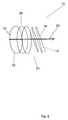
- FIG. 1is a perspective view showing the stent device along with the applied RF field and the induced RF field according to a preferred embodiment of the present invention
- FIG. 2is a perspective view showing the detailed structure of the stent body
- FIG. 3is a side view of the stent of FIG. 2 showing the detailed structure of the capacitor portion of the stent;
- FIG. 4is a cross-sectional view of the polymer coated wire forming the stent body
- FIG. 5Ais a schematic diagram showing the equivalent resonating circuit effected by the structure forming the stent device
- FIG. 5Bis a schematic diagram showing the equivalent resonating circuit effected by an alternate structure forming the stent device
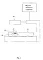
- FIG. 6is a schematic diagram showing a technique for determining the resonant frequency of the stent after implantation into the body of a patient
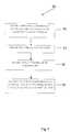
- FIG. 7is a flowchart showing a method for utilizing the stent.
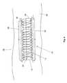
- FIG. 8is a diagram showing the electromagnetic field produced by the implanted stent.
- the stent 10includes a solenoidal body 12 having its geometry formed from a conducting wire 20 shaped into a generally helical cylindrical structure.
- the helical cylinder forming the stent body 12prevents the collapse of the artery, vessel or passageway within which the stent is implanted, thereby promoting blood flow through the stent 10 .
- the conducting wire 20is made from a nickel-titanium (NiTi) alloy.
- the nickel-titanium alloy compositioncan range from about 40% to 60% nickel with the remaining percentage being titanium.
- the helical geometry of the solenoidal body 12also forms an electrical inductor 14 having an inductance L.
- An electrical capacitor 16is formed at each end of the inductor 14 .
- the electrical capacitors 16have capacitance values of C 1 and C 2 .
- a return current path wire 22connects each capacitor 16 with the inductor 14 .
- the capacitors 16function to resonate the inductance of the solenoidal inductor 14 .
- the resulting structureforms a resonant circuit 18 (FIG. 5A) which resonates when subjected to an applied RF electromagnetic field at the resonant frequency of the circuit 18 .
- the applied electromagnetic fieldis generated at the resonant frequency of the circuit 18 which in turn re-radiates an electromagnetic field causing tissue surrounding the stent 10 to generate heat. This warming feature is described in greater detail below.
- the equivalent circuit for the stent 10can be modeled as a parallel LC resonant circuit. More specifically, the equivalent circuit 18 is shown as an inductor L, formed by the solenoidal body 12 , in parallel with two capacitors 16 having capacitance values of C 1 and C 2 .
- the stent 10is described above to include two capacitors 16 , each capacitor being connected at one end of the inductor 14 .
- the equivalent circuit 18 ′ associated with stent 10can be alternately configured to include only one capacitor C connected to the inductor L.
- the inner conductor ring 24is connected to one end of the inductor 14
- the outer conductor ring 26is connected to the opposite end of the inductor 14 via the return current wire 22 .
- the return current path wire 22is connected to the last coil forming the non-capacitive end of the stent body 12 .
- the resonant frequency f ris preferably selected such that it does not correspond to any clinical scanner frequencies, or harmonics thereof.
- the resonant frequency f rwill be established between 50 MHz to 300 MHz exclusive of 10 MHz ranges centered on the resonant frequencies used for clinical MR imaging from 1.5 T to 7.0 T.
- each capacitor 16is substantially similar in structure.
- the capacitor 16 formed at each end of the inductor 14includes an inner conducting ring 24 and a structurally parallel outer conducting ring 26 , each formed from the NiTi conducting wire 20 .
- a polymer dielectric ring 28is disposed between the inner and outer conducting rings 24 , 26 .
- the inner conducting ring 24 of each capacitor 16is electrically connected to the last coil forming the end of the inductor 14 , and preferably forms an integral structure with wire 20 that defines inductor 14 .
- the outer conducting rings 26 of capacitors 16are electrically interconnected by current path wire 22 thereby completing the LC electrical circuit.
- FIG. 3A partial side view of the reactive stent structure 10 is shown in FIG. 3 . More particularly, FIG. 3 shows the polymer dielectric ring 28 disposed between the inner and outer capacitive conductors 24 , 26 for forming the electrical capacitor 16 .
- the components forming the stent device 10are also coated with an electrical insulator, in order to confine the induced electric current path to the conducting wire 20 of the stent body 10 , and produce the desired radio frequency field geometry. More specifically, all of the NiTi conducting wire 20 forming the inductor 14 , the return path conductor 22 , and the capacitors 16 formed by the inner and outer conducting rings 24 , 26 and the polymer dielectric ring 28 , are coated with a suitable polymer material 32 .
- the polymer coated wire 30 forming the structure of the stent device 10is shown in cross-section.
- the diameter of the conducting wire 20is in the range of about 0.007 in. to 0.013 in.
- the polymer coating 32functions as an electrical insulator around the stent 10 .
- the polymer coating 32has a thickness in the range of about 50 to 400 microns.
- the polymer coating 32is a photoreactive resin which can be applied by deposition techniques or by dipping, depending on the thickness and mechanical properties desired.
- the functional aspects of the stent device 10are described in more detail.
- the geometry of the inductor 14 and the capacitors 16produces an intense induced RF field 36 around itself at the resonant frequency f r .
- the electrical pathbe solenoidal.
- this geometryallows for a highly focused induced RF field 36 near the stent body 12 that causes the tissue itself such as endothelial tissue in the immediate region of the stent 10 to generate heat by absorption of RF energy. This heating effect is responsible for the ablation of hyperplastic tissue around or within the stent 10 .
- the RF reactive stent device 10is excited by placing the subject in a resonator designed for driving the stent 10 at its self-resonant frequency f r .
- the transmitter of the resonatoris turned on at a specific power level for a specified duration and transmits an RF signal at the resonant frequency of the stent device 10 , causing the stent device 10 to resonate and produce the desired heating effect in the tissue.
- the stent device 10functions to “receive” the RF signal and re-radiate an intense induced field 36 at the resonant frequency into its immediate surroundings.
- the RF transmitter for generating the applied field 34preferably includes a frequency source, an RF amplifier, and a resonator for producing the electromagnetic field.
- the resonatorresembles an MR volume resonator and is driven by an RF amplifier of 500-1000 W output.
- An RF synthesizeris used as an adjustable frequency source in order to provide a signal at the resonant frequency f r of the implanted stent, which is then amplified and fed to the resonator.
- Determining the resonant frequencyis accomplished using an inductive coupling technique, and preferably using a device known as a “dip meter” .
- This techniqueis described further with respect to FIG. 6 . More specifically, FIG. 6 shows the stent 10 implanted within a patient's body 42 .
- a resonant circuitsuch as the circuit 18 formed by the stent 10
- the meter 38is tuned to the resonant frequency of the circuit 18
- resonanceis indicated by a change in the bias current of the oscillator associated with the dip meter 38 , seen as a “dip” on the current meter.
- the operating frequency of the dip meter 38can be varied to identify the unknown resonant frequency of the resonant circuit 18 formed by the stent 10 without physical or direct electrical contact with the stent 10 .
- the applied RF field 34is not present or utilized during the procedure of determining the resonant frequency of the implanted stent 10 using the dip meter 38 .
- the dip meter 38is removed from the field of the transmit resonator 44 when the stent is irradiated by the applied RF field 34 .
- a method for ablating tissue either surrounding or within the stent device 10is shown at 50 .
- the methodincludes at 52 the step of providing an RF reactive stent 10 formed from a solenoidal inductor 14 and a capacitor 16 which together define an electrical circuit 18 , 18 ′having a resonant frequency as described above.
- the stent device 10is then implanted within a vessel of a body at 54 .
- the resonant frequency of the stent device 10is identified at 56 .
- One technique for identifying the resonant frequencyis through the use of a dip meter 38 as described above.
- the implanted stent device 10is then irradiated at 58 with an applied RF electromagnetic field at the resonant frequency of the stent 10 which causes the stent to resonate and produce an induced RF field at the resonant frequency.
- the stent device 10is shown as being implanted within a vessel 46 of a body 42 . Also shown is that after the resonant frequency is identified, the stent 10 is irradiated with the applied RF field 34 at the resonant frequency. As the stent 10 begins resonating, current begins conducting through the inductor 14 and capacitor 16 forming the stent 10 , and the induced RF field 36 is produced. The induced RF field 36 then causes the tissue surrounding the stent 10 to generate heat for producing the desired ablation effect described above.
- the stent device 10 of the present inventionincludes many advantages over known medical stents.
- the geometry of the stent device 10results in the generation of an intense solenoidal RF electromagnetic field confined primarily to the vascular endothelium.
- the stent device 10allows tracking of blood flow post primary stent placement, and determination of any hyperplasic or restenotic response associated with the patient.
- the same stent device 10can subsequently be used for producing an ablation field by using specific solenoidal geometry.
- the stent device 10 of the present inventionis fully MR compatible, the stent 10 can be used for uniformly ablating the endothelium surrounding it, rather than ablating spots, as is currently done with ablation catheterization procedures. Thus, periodic re-ablation can be performed in a completely non-invasive manner.
- the NiTi material forming the stent device 10does not appear to produce any significant artifacting (signal loss) in the resulting MR images as do medical stents formed from stainless steel.
- the NiTi materialallows the MR imaging system to image tissue surrounding the stent 10 and tissue inside the stent 10 without being blocked by the stent body 12 .
- the NiTi structure forming the stent 10provides many significant advantages over stent geometries formed from stainless steel which typically does not allow tissue within the stent to be imaged.
- the stent 10 described hereinmay be utilized in a variety of therapeutic applications including but not limited to: shunts, shunts used for dialysis, artificial veins, arteries and grafts, esophageal stenosis, esophageal cancer, esophageal varacies, lung bronchi for cancer treatment, urethra, hydrocephalus shunt tubes, trachea, middle ear tubes, lymphatic ducts and grafts, gastrointestinal stenosis and inflammatory diseases (e.g. Crohn's disease), pyloric stenosis, and biliary atresia.
- shuntsused for dialysis, artificial veins, arteries and grafts
- esophageal stenosisesophageal cancer
- esophageal varaciesesophageal varacies
- lung bronchifor cancer treatment
- urethrahydrocephalus s
Landscapes
- Health & Medical Sciences (AREA)
- Engineering & Computer Science (AREA)
- Biomedical Technology (AREA)
- Cardiology (AREA)
- Oral & Maxillofacial Surgery (AREA)
- Transplantation (AREA)
- Heart & Thoracic Surgery (AREA)
- Vascular Medicine (AREA)
- Life Sciences & Earth Sciences (AREA)
- Animal Behavior & Ethology (AREA)
- General Health & Medical Sciences (AREA)
- Public Health (AREA)
- Veterinary Medicine (AREA)
- Media Introduction/Drainage Providing Device (AREA)
- Prostheses (AREA)
Abstract
Description
This invention relates to a stent used in conjunction with a magnetic resonance (MR) system, and more particularly to a stent which is capable of repeatedly ablating hyperplastic tissue growing around the stent when the stent is subjected to an RF electromagnetic field produced by an external scanner, thus preventing blockage of the stent.
Magnetic Resonance (MR) surface resonators are currently used in a variety of clinical and research applications. The purpose of a surface resonator is to provide improved signal-to-noise performance when imaging small regions. Typically, the resonator is placed on the surface of the body over the region of interest. The surface resonator can be used as a transmit/receive antenna, or, as in many applications, the volume resonator (sometimes referred to as a body coil) of the MR scanner will be used as the transmit antenna, while the surface resonator acts as the receive antenna to collect the MR signal from the desired region alone.
One area of concern when designing MR surface resonators for use as receive antennas is the decoupling issue. More specifically, if a surface resonator with the same resonant frequency as the transmit field is placed inside a volume resonator while the volume resonator is transmitting, the surface resonator will receive and retransmit an intense field around itself. This retransmitted field can result in RF burns to the patient. In order to prevent surface burns, the surface resonator is “decoupled” during the volume resonator transmit procedure. The surface resonator is decoupled by causing its resonant frequency to change during volume resonator transmit. A diode switching circuit is used to add an additional reactive element to the resonant circuit while transmit is taking place. For example, an additional inductor added to a resonant circuit will lower the resonant frequency. When the resonant frequency of the surface resonator is sufficiently far from the transmit frequency, the surface resonator will not receive and retransmit a signal, and the RF burn hazard is eliminated.
Known treatments for removing or preventing hyperplastic tissue located within an implanted stent body utilize invasive procedures, such as inserting a catheter into the area near the stent. The catheter is designed to include an antenna at its terminal end. The catheter can then be used as a radio frequency transmit path for ablating tissue that could otherwise create blockage within the vessel. However, such invasive procedures are significantly complex, present higher risks of post procedure complications and can be very uncomfortable for the patient. There are also limits on the number of catheter procedures which can be performed on a patient who is more susceptible to a hyperplastic response.
In one aspect, the invention features a stent device. The stent device includes an electrically conductive helical structure. The stent device also includes an electrically conductive ring structure connected to the helical structure. The ring structure includes an inner conducting ring, an outer conducting ring, and a dielectric material disposed between the inner and outer conducting rings. The helical structure and the ring structure are arranged to produce an electromagnetic field when subjected to an applied electromagnetic field.
Embodiments may include one or more of the following features. The ring structure is connected to a first end of the helical structure, and further includes a second ring structure connected to a second, opposite end of the helical structure. The inner conducting ring, the outer conducting ring, and the dielectric material disposed between the inner and outer conducting rings are arranged for defining an electrical capacitor. The inner conducting rings of the ring structures are connected to the first end and the second end of the helical structure, respectively, and further include a return path conductor electrically interconnecting the first ring structure and the second ring structure. The return path conductor is connected to the outer conducting ring of each ring structure.
The helical structure defines a solenoidal inductor for conducting an electrical current. The helical structure and the ring structure define an electrically reactive circuit having a resonant frequency. The helical structure and the ring structure produce the electromagnetic field at the resonant frequency. In one configuration, the helical structure and the inner and outer conducting ring of each ring structure are formed from a nickel-titanium alloy. The nickel-titanium alloy comprises about 40% to 60% nickel.
In another aspect, the invention features a stent for implantation into a vessel of a body. The stent includes a solenoidal inductor formed by a helical wire structure and a capacitor is connected at each end of the inductor. A return path conductor electrically interconnects the capacitors. The inductor and the capacitor are arranged to radiate an electromagnetic field when subjected to an applied electromagnetic field.
Embodiments may include one or more of the following features. Each capacitor includes an inner conducting ring, an outer conducting ring, and a dielectric material disposed between the inner and outer conducting rings. The inner conducting rings of the capacitors are connected to a first end and a second end of the helical wire structure, respectively, and the return path conductor is connected to the outer conducting rings of the capacitors. The conductor is electrically connected in parallel with the capacitors. The inductor, the inner conducting ring and outer conducting ring of each capacitor, and the return path conductor are formed from a nickel-titanium wire structure. The inductor and the capacitors define an electrically reactive circuit having a resonant frequency. The applied electromagnetic field is transmitted by a magnetic resonance transmitter at the resonant frequency. The electrically reactive circuit radiates the electromagnetic field at the resonant frequency.
In another aspect, the invention features an RF reactive stent for implantation into a vessel of a body. The stent includes a solenoidal inductor for conducting an induced current. The inductor is formed from a helical wire structure having a first end and a second end. A first capacitor is connected to the first end of the inductor, and a second capacitor is connected to the second end of the inductor. A return path conductor electrically interconnects the first capacitor, the second capacitor and the solenoidal inductor as an electrically reactive circuit. The electrically reactive circuit forming the stent has a resonant frequency. The first capacitor, the second capacitor and the solenoidal inductor are arranged to generate an RF field when subjected to an applied RF field at the resonant frequency of the stent.
Embodiments may include one or more of the following features. The first and second capacitors are each formed by a ring structure having an inner conducting ring, an outer conducting ring, and a dielectric material disposed between the inner and outer conducting rings. The inductor, the first and second capacitors, and the return path conductor are coated with an insulating material. In one configuration, the insulating material is a polymer. The inductor, the inner and outer conducting rings of each capacitor, and the return path conductor are formed from a nickel-titanium wire structure.
In another aspect, the invention features a method for ablating tissue surrounding a reactive stent device. The method includes the steps of providing an RF reactive stent formed from a solenoidal inductor element which is electrically interconnected to a capacitor element. The method also includes implanting the stent within a vessel of a body, and irradiating the stent with an applied RF field for causing the inductor element and the capacitor element to generate an RF field in the vessel.
Embodiments may include one or more of the following features. The stent has a resonant frequency and the stent is irradiated by the applied RF field at the resonant frequency. The method includes the step of identifying the resonant frequency associated with the stent after the step of implanting the stent. The RF field generated by the inductor element and the capacitor element causes heating of tissue forming the vessel. The step of irradiating the stent produces a selected amount of heat sufficient to cause ablation of the tissue, which may be hyperplastic tissue surrounding the stent.
The details of one or more embodiments of the invention are set forth in the accompanying drawings and the description below. Other features, objects, and advantages of the invention will be apparent from the description and drawings, and from the claims.
FIG. 1 is a perspective view showing the stent device along with the applied RF field and the induced RF field according to a preferred embodiment of the present invention;
FIG. 2 is a perspective view showing the detailed structure of the stent body;
FIG. 3 is a side view of the stent of FIG. 2 showing the detailed structure of the capacitor portion of the stent;
FIG. 4 is a cross-sectional view of the polymer coated wire forming the stent body;
FIG. 5A is a schematic diagram showing the equivalent resonating circuit effected by the structure forming the stent device;
FIG. 5B is a schematic diagram showing the equivalent resonating circuit effected by an alternate structure forming the stent device;
FIG. 6 is a schematic diagram showing a technique for determining the resonant frequency of the stent after implantation into the body of a patient;
FIG. 7 is a flowchart showing a method for utilizing the stent; and
FIG. 8 is a diagram showing the electromagnetic field produced by the implanted stent.
Like reference symbols in the various drawings indicate like elements.
Turning to FIG. 1, the RF reactive stent is shown. More specifically, thestent 10 includes asolenoidal body 12 having its geometry formed from aconducting wire 20 shaped into a generally helical cylindrical structure. The helical cylinder forming thestent body 12 prevents the collapse of the artery, vessel or passageway within which the stent is implanted, thereby promoting blood flow through thestent 10. Theconducting wire 20 is made from a nickel-titanium (NiTi) alloy. The nickel-titanium alloy composition can range from about 40% to 60% nickel with the remaining percentage being titanium. The helical geometry of thesolenoidal body 12 also forms anelectrical inductor 14 having an inductance L. Anelectrical capacitor 16 is formed at each end of theinductor 14. Theelectrical capacitors 16 have capacitance values of C1and C2. A returncurrent path wire 22 connects eachcapacitor 16 with theinductor 14. As will be described in greater detail below, thecapacitors 16 function to resonate the inductance of thesolenoidal inductor 14. The resulting structure forms a resonant circuit18 (FIG. 5A) which resonates when subjected to an applied RF electromagnetic field at the resonant frequency of thecircuit 18. The applied electromagnetic field is generated at the resonant frequency of thecircuit 18 which in turn re-radiates an electromagnetic field causing tissue surrounding thestent 10 to generate heat. This warming feature is described in greater detail below.
Referring briefly to FIG. 5A the equivalent circuit for thestent 10 can be modeled as a parallel LC resonant circuit. More specifically, theequivalent circuit 18 is shown as an inductor L, formed by thesolenoidal body 12, in parallel with twocapacitors 16 having capacitance values of C1and C2. The resulting device is a parallel inductor/capacitor (LC)circuit 18 having a resonant frequency frgiven by the following formula.

Thestent 10 is described above to include twocapacitors 16, each capacitor being connected at one end of theinductor 14. However, as shown in FIG. 5B, theequivalent circuit 18′ associated withstent 10 can be alternately configured to include only one capacitor C connected to the inductor L. In this alternate configuration theinner conductor ring 24 is connected to one end of theinductor 14, and theouter conductor ring 26 is connected to the opposite end of theinductor 14 via the returncurrent wire 22. If asingle capacitor 16 is used, the resonant frequency fris given by:

in which case the returncurrent path wire 22 is connected to the last coil forming the non-capacitive end of thestent body 12.
The resonant frequency fris preferably selected such that it does not correspond to any clinical scanner frequencies, or harmonics thereof. Preferably, the resonant frequency frwill be established between 50 MHz to 300 MHz exclusive of 10 MHz ranges centered on the resonant frequencies used for clinical MR imaging from 1.5 T to 7.0 T. Exemplary values for L and C will depend on the size and application of the stent. Possible L and C values for a coronary stent circuit may be L=1.0 μH, C=0.5 pF, fr=225 MHz wherein the values are in the range of L=0.3-1.2 μH and C=0.3-0.7 pF. Possible L and C values for a carotid stent circuit may be L=3.0 μH, C=0.8 pF, fr=103 MHz wherein the values are in the range of L=1.0-4.0 μH and C=0.6-1.0 pF.
Referring to FIG. 2, the detailed structure of eachcapacitor 16 is shown. While only onecapacitor 16 is shown in detail, it should be understood that eachcapacitor 16 is substantially similar in structure. Thecapacitor 16 formed at each end of theinductor 14 includes aninner conducting ring 24 and a structurally parallel outer conductingring 26, each formed from theNiTi conducting wire 20. Apolymer dielectric ring 28 is disposed between the inner and outer conducting rings24,26. Theinner conducting ring 24 of eachcapacitor 16 is electrically connected to the last coil forming the end of theinductor 14, and preferably forms an integral structure withwire 20 that definesinductor 14. The outer conducting rings26 ofcapacitors 16 are electrically interconnected bycurrent path wire 22 thereby completing the LC electrical circuit.
A partial side view of thereactive stent structure 10 is shown in FIG.3. More particularly, FIG. 3 shows thepolymer dielectric ring 28 disposed between the inner and outercapacitive conductors electrical capacitor 16. The components forming thestent device 10 are also coated with an electrical insulator, in order to confine the induced electric current path to theconducting wire 20 of thestent body 10, and produce the desired radio frequency field geometry. More specifically, all of theNiTi conducting wire 20 forming theinductor 14, thereturn path conductor 22, and thecapacitors 16 formed by the inner and outer conducting rings24,26 and thepolymer dielectric ring 28, are coated with asuitable polymer material 32.
Turning briefly to FIG. 4, the polymer coatedwire 30 forming the structure of thestent device 10 is shown in cross-section. The diameter of theconducting wire 20 is in the range of about 0.007 in. to 0.013 in. As will be appreciated, thepolymer coating 32 functions as an electrical insulator around thestent 10. Thepolymer coating 32 has a thickness in the range of about 50 to 400 microns. Thepolymer coating 32 is a photoreactive resin which can be applied by deposition techniques or by dipping, depending on the thickness and mechanical properties desired.
Referring back to FIG. 1, the functional aspects of thestent device 10 are described in more detail. In operation, when thestent device 10 is subjected to an appliedRF field 34, the geometry of theinductor 14 and thecapacitors 16 produces an intense inducedRF field 36 around itself at the resonant frequency fr. In order to generate the proper field geometry it is preferred that the electrical path be solenoidal. As such, this geometry allows for a highly focused inducedRF field 36 near thestent body 12 that causes the tissue itself such as endothelial tissue in the immediate region of thestent 10 to generate heat by absorption of RF energy. This heating effect is responsible for the ablation of hyperplastic tissue around or within thestent 10.
Once in place, for example within an artery, the RFreactive stent device 10 is excited by placing the subject in a resonator designed for driving thestent 10 at its self-resonant frequency fr. The transmitter of the resonator is turned on at a specific power level for a specified duration and transmits an RF signal at the resonant frequency of thestent device 10, causing thestent device 10 to resonate and produce the desired heating effect in the tissue. Thestent device 10 functions to “receive” the RF signal and re-radiate an intense inducedfield 36 at the resonant frequency into its immediate surroundings. Absorption of RF energy from the re-radiated field by the vascular endothelium is intended to raise the temperature of the surrounding endothelial tissue to approximately 60° C. This temperature increase serves to ablate the surrounding tissue and to prevent further proliferation of the endothelial cells. The RF transmitter for generating the appliedfield 34 preferably includes a frequency source, an RF amplifier, and a resonator for producing the electromagnetic field. The resonator resembles an MR volume resonator and is driven by an RF amplifier of 500-1000 W output. An RF synthesizer is used as an adjustable frequency source in order to provide a signal at the resonant frequency frof the implanted stent, which is then amplified and fed to the resonator.
As will be appreciated by one skilled in the art, it is important to know the exact resonant frequency of thestent 10 once it is implanted within the body. This is because the resonant frequency of thestent 10 will likely shift or change slightly after being implanted. Reasons for a resonant frequency shift include mechanical deformation of the stent, electric field losses in the conducting medium of blood and tissue, and dielectric effects of blood and tissue.
Determining the resonant frequency is accomplished using an inductive coupling technique, and preferably using a device known as a “dip meter” . This technique is described further with respect to FIG.6. More specifically, FIG. 6 shows thestent 10 implanted within a patient'sbody 42. When theinductive loop 40 of thedip meter 38 is placed in proximity to a resonant circuit, such as thecircuit 18 formed by thestent 10, and themeter 38 is tuned to the resonant frequency of thecircuit 18, resonance is indicated by a change in the bias current of the oscillator associated with thedip meter 38, seen as a “dip” on the current meter. Thus, the operating frequency of thedip meter 38 can be varied to identify the unknown resonant frequency of theresonant circuit 18 formed by thestent 10 without physical or direct electrical contact with thestent 10. It should be noted that the appliedRF field 34 is not present or utilized during the procedure of determining the resonant frequency of the implantedstent 10 using thedip meter 38. Further, thedip meter 38 is removed from the field of the transmitresonator 44 when the stent is irradiated by the appliedRF field 34.
With reference to FIG. 7, a method for ablating tissue either surrounding or within thestent device 10 is shown at50. The method includes at52 the step of providing an RFreactive stent 10 formed from asolenoidal inductor 14 and acapacitor 16 which together define anelectrical circuit stent device 10 is then implanted within a vessel of a body at54. After the stent device is implanted, the resonant frequency of thestent device 10 is identified at56. One technique for identifying the resonant frequency is through the use of adip meter 38 as described above. The implantedstent device 10 is then irradiated at58 with an applied RF electromagnetic field at the resonant frequency of thestent 10 which causes the stent to resonate and produce an induced RF field at the resonant frequency.
Referring to FIG. 8, thestent device 10 is shown as being implanted within avessel 46 of abody 42. Also shown is that after the resonant frequency is identified, thestent 10 is irradiated with the appliedRF field 34 at the resonant frequency. As thestent 10 begins resonating, current begins conducting through theinductor 14 andcapacitor 16 forming thestent 10, and the inducedRF field 36 is produced. The inducedRF field 36 then causes the tissue surrounding thestent 10 to generate heat for producing the desired ablation effect described above.
Thestent device 10 of the present invention includes many advantages over known medical stents. The geometry of thestent device 10 results in the generation of an intense solenoidal RF electromagnetic field confined primarily to the vascular endothelium. For example, thestent device 10 allows tracking of blood flow post primary stent placement, and determination of any hyperplasic or restenotic response associated with the patient. Thesame stent device 10 can subsequently be used for producing an ablation field by using specific solenoidal geometry. Because thestent device 10 of the present invention is fully MR compatible, thestent 10 can be used for uniformly ablating the endothelium surrounding it, rather than ablating spots, as is currently done with ablation catheterization procedures. Thus, periodic re-ablation can be performed in a completely non-invasive manner.
The NiTi material forming thestent device 10 does not appear to produce any significant artifacting (signal loss) in the resulting MR images as do medical stents formed from stainless steel. As a result, the NiTi material allows the MR imaging system to image tissue surrounding thestent 10 and tissue inside thestent 10 without being blocked by thestent body 12. Accordingly, the NiTi structure forming thestent 10 provides many significant advantages over stent geometries formed from stainless steel which typically does not allow tissue within the stent to be imaged.
Thestent 10 described herein may be utilized in a variety of therapeutic applications including but not limited to: shunts, shunts used for dialysis, artificial veins, arteries and grafts, esophageal stenosis, esophageal cancer, esophageal varacies, lung bronchi for cancer treatment, urethra, hydrocephalus shunt tubes, trachea, middle ear tubes, lymphatic ducts and grafts, gastrointestinal stenosis and inflammatory diseases (e.g. Crohn's disease), pyloric stenosis, and biliary atresia.
A number of embodiments of the invention have been described. Nevertheless, it will be understood that various modifications may be made without departing from the spirit and scope of the invention. Accordingly, other embodiments are within the scope of the following claims.
Claims (29)
1. A stent device comprising:
an electrically conductive helical structure; and
an electrically conductive ring structure connected to the helical structure, the ring structure including an inner conducting ring, an outer conducting ring, and a dielectric material disposed between the inner and outer conducting rings;
the helical structure and the ring structure being arranged to produce an electromagnetic field when subjected to an applied electromagnetic field.
2. The stent device ofclaim 1 wherein said ring structure is connected to a first end of the helical structure, and further comprising a second said ring structure connected to a second, opposite end of the helical structure.
3. The stent device ofclaim 1 wherein the inner conducting ring, the outer conducting ring, and the dielectric material disposed between the inner and outer conducting rings define an electrical capacitor.
4. The stent device ofclaim 2 wherein the inner conducting rings of said ring structures are connected to said first end and said second end of said helical structure, respectively, and further including a return path conductor electrically interconnecting the first said ring structure and the second said ring structure.
5. The stent device ofclaim 4 wherein the return path conductor is connected to the outer conducting ring of each said ring structure.
6. The stent device ofclaim 1 wherein the helical structure defines a solenoidal inductor for conducting an electrical current.
7. The stent device ofclaim 1 wherein the helical structure and the ring structure define an electrically reactive circuit having a resonant frequency.
8. The stent device ofclaim 7 wherein the helical structure and the ring structure produce the electromagnetic field at the resonant frequency.
9. The stent device ofclaim 2 wherein the helical structure and the inner and outer conducting ring of each ring structure are formed from a nickel-titanium alloy.
10. The stent device ofclaim 9 wherein the nickel-titanium alloy comprises about 40% to 60% nickel.
11. A stent for implantation into a vessel of a body comprising:
a solenoidal inductor formed by a helical wire structure;
a capacitor connected at each end of the inductor; and
a return path conductor electrically interconnecting the capacitors;
the inductor and the capacitor being arranged to radiate an electromagnetic field when subjected to an applied electromagnetic field.
12. The stent ofclaim 11 wherein each said capacitor includes an inner conducting ring, an outer conducting ring, and a dielectric material disposed between the inner and outer conducting rings.
13. The stent ofclaim 12 wherein the inner conducting rings of said capacitors are connected to a first end and a second end of the helical wire structure, respectively, and the return path conductor is connected to the outer conducting rings of said capacitors.
14. The stent ofclaim 13 wherein the inductor is electrically connected in parallel with said capacitors.
15. The stent ofclaim 14 wherein the inductor, the inner conducting ring and outer conducting ring of each capacitor, and the return path conductor are formed from a nickel-titanium wire structure.
16. The stent ofclaim 11 wherein the inductor and the capacitors define an electrically reactive circuit having a resonant frequency.
17. The stent ofclaim 16 wherein the applied electromagnetic field is transmitted by a magnetic resonance transmitter at the resonant frequency.
18. The stent ofclaim 16 wherein the electrically reactive circuit radiates the electromagnetic field at the resonant frequency.
19. An RF reactive stent for implantation into a vessel of a body comprising:
a solenoidal inductor for conducting an induced current, the inductor being formed from a helical wire structure having a first end and a second end;
a first capacitor connected to the first end of the inductor;
a second capacitor connected to the second end of the inductor;
a return path conductor electrically interconnecting the first capacitor, the second capacitor and the solenoidal inductor as an electrically reactive circuit having a resonant frequency;
the first capacitor, the second capacitor and the solenoidal inductor being arranged to generate an RF field when subjected to an applied RF field at the resonant frequency of the stent.
20. The stent ofclaim 19 wherein the first and second capacitors are each formed by a ring structure having an inner conducting ring, an outer conducting ring, and a dielectric material disposed between the inner and outer conducting rings.
21. The stent ofclaim 19 wherein the inductor, the first and second capacitors, and the return path conductor are coated with an insulating material.
22. The stent ofclaim 21 wherein the insulating material is a polymer.
23. The stent ofclaim 20 wherein the inductor, the inner and outer conducting rings of each capacitor, and the return path conductor are formed from a nickel-titanium wire structure.
24. A method for ablating tissue surrounding a reactive stent device comprising:
providing an RF reactive stent formed from a solenoidal inductor element electrically interconnected to a capacitor element;
implanting the stent within a vessel of a body; and
irradiating the stent with an applied RF field to cause the inductor element and the capacitor element to generate an RF field in the vessel.
25. The method ofclaim 24 wherein the stent has a resonant frequency and the stent is irradiated by the applied RF field at the resonant frequency.
26. The method ofclaim 25 further including the step of identifying the resonant frequency associated with the stent after the step of implanting the stent.
27. The method ofclaim 24 wherein the RF field generated by the inductor element and the capacitor element causes heating of tissue forming the vessel.
28. The method ofclaim 27 wherein the step of irradiating the stent device produces a selected amount of heat sufficient to cause ablation of the tissue.
29. The method ofclaim 28 wherein the tissue is hyperplastic tissue.
Priority Applications (4)
| Application Number | Priority Date | Filing Date | Title |
|---|---|---|---|
| US09/685,098US6802857B1 (en) | 2000-10-11 | 2000-10-11 | MRI stent |
| CA002425813ACA2425813A1 (en) | 2000-10-11 | 2001-10-11 | Mri stent |
| PCT/US2001/031906WO2002030331A1 (en) | 2000-10-11 | 2001-10-11 | Mri stent |
| AU2002213152AAU2002213152A1 (en) | 2000-10-11 | 2001-10-11 | Mri stent |
Applications Claiming Priority (1)
| Application Number | Priority Date | Filing Date | Title |
|---|---|---|---|
| US09/685,098US6802857B1 (en) | 2000-10-11 | 2000-10-11 | MRI stent |
Publications (1)
| Publication Number | Publication Date |
|---|---|
| US6802857B1true US6802857B1 (en) | 2004-10-12 |
Family
ID=24750768
Family Applications (1)
| Application Number | Title | Priority Date | Filing Date |
|---|---|---|---|
| US09/685,098Expired - Fee RelatedUS6802857B1 (en) | 2000-10-11 | 2000-10-11 | MRI stent |
Country Status (4)
| Country | Link |
|---|---|
| US (1) | US6802857B1 (en) |
| AU (1) | AU2002213152A1 (en) |
| CA (1) | CA2425813A1 (en) |
| WO (1) | WO2002030331A1 (en) |
Cited By (121)
| Publication number | Priority date | Publication date | Assignee | Title |
|---|---|---|---|---|
| US20020128704A1 (en)* | 2001-03-07 | 2002-09-12 | Wolfgang Daum | Stent and method for drug delivery from stents |
| US20020183829A1 (en)* | 2001-03-20 | 2002-12-05 | Claas Doscher | Material for medical stents and device for the intracorporeal inductive heating of these stents |
| US20040149294A1 (en)* | 2002-12-16 | 2004-08-05 | Gianchandani Yogesh B. | Assembly and planar structure for use therein which is expandable into a 3-D structure such as a stent and device for making the planar structure |
| US20050049480A1 (en)* | 2003-08-25 | 2005-03-03 | Biophan Technologies, Inc. | Electromagnetic radiation transparent device and method of making thereof |
| US20050080346A1 (en)* | 2002-12-16 | 2005-04-14 | The Regents Of The University Of Michigan | Antenna stent device for wireless, intraluminal monitoring |
| US20050101946A1 (en)* | 2003-11-11 | 2005-05-12 | Biosense Webster Inc. | Externally applied RF for pulmonary vein isolation |
| US20050178584A1 (en)* | 2002-01-22 | 2005-08-18 | Xingwu Wang | Coated stent and MR imaging thereof |
| US20060020313A1 (en)* | 2002-01-18 | 2006-01-26 | Calfacior Corporation Now Apsara Medical Corporation | System, method and apparatus for evaluating tissue temperature |
| US20060105016A1 (en)* | 2004-11-12 | 2006-05-18 | Gray Robert W | Device compatible with magnetic resonance imaging |
| WO2006083478A1 (en)* | 2005-02-04 | 2006-08-10 | Boston Scientific Limited | Resonator for medical device |
| US20060195134A1 (en)* | 2005-02-28 | 2006-08-31 | Medtronic Vascular, Inc. | Device, system, and method for aiding valve annuloplasty |
| US20060287705A1 (en)* | 2005-05-24 | 2006-12-21 | Boston Scientific Scimed, Inc. | Resonator for medical device |
| US20060287648A1 (en)* | 2005-06-16 | 2006-12-21 | Yitzhack Schwartz | Less invasive methods for ablation of fat pads |
| US20070010740A1 (en)* | 2005-05-19 | 2007-01-11 | Biophan Technologies, Inc. | Electromagnetic resonant circuit sleeve for implantable medical device |
| US20070032861A1 (en)* | 2005-08-08 | 2007-02-08 | Boston Scientific Scimed, Inc. | MRI resonator system with stent implant |
| US7279664B2 (en) | 2005-07-26 | 2007-10-09 | Boston Scientific Scimed, Inc. | Resonator for medical device |
| US20070238979A1 (en)* | 2006-03-23 | 2007-10-11 | Medtronic Vascular, Inc. | Reference Devices for Placement in Heart Structures for Visualization During Heart Valve Procedures |
| US20070239256A1 (en)* | 2006-03-22 | 2007-10-11 | Jan Weber | Medical devices having electrical circuits with multilayer regions |
| US7304277B2 (en) | 2005-08-23 | 2007-12-04 | Boston Scientific Scimed, Inc | Resonator with adjustable capacitor for medical device |
| US20070288000A1 (en)* | 2006-04-19 | 2007-12-13 | Medtronic Vascular, Inc. | Method for Aiding Valve Annuloplasty |
| US20080051838A1 (en)* | 2006-08-24 | 2008-02-28 | Shuros Allan C | Integrated cardiac rhythm management system with heart valve |
| US7423496B2 (en) | 2005-11-09 | 2008-09-09 | Boston Scientific Scimed, Inc. | Resonator with adjustable capacitance for medical device |
| US20090027280A1 (en)* | 2005-05-05 | 2009-01-29 | Frangioni John V | Micro-scale resonant devices and methods of use |
| WO2006102235A3 (en)* | 2005-03-21 | 2009-04-02 | Nanoset Llc | Mri imageable medical device |
| WO2007044448A3 (en)* | 2005-10-06 | 2009-04-23 | Univ Johns Hopkins | Mri compatible vascular occlusive devices and related methods of treatment and methods of monitoring implanted devices |
| US7524282B2 (en) | 2005-08-29 | 2009-04-28 | Boston Scientific Scimed, Inc. | Cardiac sleeve apparatus, system and method of use |
| US20090179716A1 (en)* | 2008-01-09 | 2009-07-16 | Anaren, Inc. | RF Filter Device |
| US20100115637A1 (en)* | 2008-10-27 | 2010-05-06 | Baxter International Inc. | Models of thrombotic thrombocytopenic purpura and methods of use thereof |
| US8473067B2 (en) | 2010-06-11 | 2013-06-25 | Boston Scientific Scimed, Inc. | Renal denervation and stimulation employing wireless vascular energy transfer arrangement |
| WO2013149684A1 (en)* | 2012-04-02 | 2013-10-10 | Flux Medical N.V. | Implant device and system for ablation of a renal arterial wall from the inside |
| US8768486B2 (en) | 2006-12-11 | 2014-07-01 | Medtronic, Inc. | Medical leads with frequency independent magnetic resonance imaging protection |
| WO2014144708A1 (en) | 2013-03-15 | 2014-09-18 | The Regents Of The University Of California | Peptides having reduced toxicity that stimulate cholesterol efflux |
| US8939970B2 (en) | 2004-09-10 | 2015-01-27 | Vessix Vascular, Inc. | Tuned RF energy and electrical tissue characterization for selective treatment of target tissues |
| US8951251B2 (en) | 2011-11-08 | 2015-02-10 | Boston Scientific Scimed, Inc. | Ostial renal nerve ablation |
| US8974451B2 (en) | 2010-10-25 | 2015-03-10 | Boston Scientific Scimed, Inc. | Renal nerve ablation using conductive fluid jet and RF energy |
| US9023034B2 (en) | 2010-11-22 | 2015-05-05 | Boston Scientific Scimed, Inc. | Renal ablation electrode with force-activatable conduction apparatus |
| US9028472B2 (en) | 2011-12-23 | 2015-05-12 | Vessix Vascular, Inc. | Methods and apparatuses for remodeling tissue of or adjacent to a body passage |
| US9028485B2 (en) | 2010-11-15 | 2015-05-12 | Boston Scientific Scimed, Inc. | Self-expanding cooling electrode for renal nerve ablation |
| US9050106B2 (en) | 2011-12-29 | 2015-06-09 | Boston Scientific Scimed, Inc. | Off-wall electrode device and methods for nerve modulation |
| US9060761B2 (en) | 2010-11-18 | 2015-06-23 | Boston Scientific Scime, Inc. | Catheter-focused magnetic field induced renal nerve ablation |
| US9079000B2 (en) | 2011-10-18 | 2015-07-14 | Boston Scientific Scimed, Inc. | Integrated crossing balloon catheter |
| US9084609B2 (en) | 2010-07-30 | 2015-07-21 | Boston Scientific Scime, Inc. | Spiral balloon catheter for renal nerve ablation |
| US9089350B2 (en) | 2010-11-16 | 2015-07-28 | Boston Scientific Scimed, Inc. | Renal denervation catheter with RF electrode and integral contrast dye injection arrangement |
| US9119600B2 (en) | 2011-11-15 | 2015-09-01 | Boston Scientific Scimed, Inc. | Device and methods for renal nerve modulation monitoring |
| US9119632B2 (en) | 2011-11-21 | 2015-09-01 | Boston Scientific Scimed, Inc. | Deflectable renal nerve ablation catheter |
| US9125666B2 (en) | 2003-09-12 | 2015-09-08 | Vessix Vascular, Inc. | Selectable eccentric remodeling and/or ablation of atherosclerotic material |
| US9125667B2 (en) | 2004-09-10 | 2015-09-08 | Vessix Vascular, Inc. | System for inducing desirable temperature effects on body tissue |
| US9155589B2 (en) | 2010-07-30 | 2015-10-13 | Boston Scientific Scimed, Inc. | Sequential activation RF electrode set for renal nerve ablation |
| US9162046B2 (en) | 2011-10-18 | 2015-10-20 | Boston Scientific Scimed, Inc. | Deflectable medical devices |
| US9173696B2 (en) | 2012-09-17 | 2015-11-03 | Boston Scientific Scimed, Inc. | Self-positioning electrode system and method for renal nerve modulation |
| US9186210B2 (en) | 2011-10-10 | 2015-11-17 | Boston Scientific Scimed, Inc. | Medical devices including ablation electrodes |
| US9186209B2 (en) | 2011-07-22 | 2015-11-17 | Boston Scientific Scimed, Inc. | Nerve modulation system having helical guide |
| US9192435B2 (en) | 2010-11-22 | 2015-11-24 | Boston Scientific Scimed, Inc. | Renal denervation catheter with cooled RF electrode |
| US9192790B2 (en) | 2010-04-14 | 2015-11-24 | Boston Scientific Scimed, Inc. | Focused ultrasonic renal denervation |
| US9220558B2 (en) | 2010-10-27 | 2015-12-29 | Boston Scientific Scimed, Inc. | RF renal denervation catheter with multiple independent electrodes |
| US9220561B2 (en) | 2011-01-19 | 2015-12-29 | Boston Scientific Scimed, Inc. | Guide-compatible large-electrode catheter for renal nerve ablation with reduced arterial injury |
| US9265969B2 (en) | 2011-12-21 | 2016-02-23 | Cardiac Pacemakers, Inc. | Methods for modulating cell function |
| US9277955B2 (en) | 2010-04-09 | 2016-03-08 | Vessix Vascular, Inc. | Power generating and control apparatus for the treatment of tissue |
| US9289255B2 (en) | 2002-04-08 | 2016-03-22 | Medtronic Ardian Luxembourg S.A.R.L. | Methods and apparatus for renal neuromodulation |
| US9297845B2 (en) | 2013-03-15 | 2016-03-29 | Boston Scientific Scimed, Inc. | Medical devices and methods for treatment of hypertension that utilize impedance compensation |
| US9326751B2 (en) | 2010-11-17 | 2016-05-03 | Boston Scientific Scimed, Inc. | Catheter guidance of external energy for renal denervation |
| US9327100B2 (en) | 2008-11-14 | 2016-05-03 | Vessix Vascular, Inc. | Selective drug delivery in a lumen |
| US9358365B2 (en) | 2010-07-30 | 2016-06-07 | Boston Scientific Scimed, Inc. | Precision electrode movement control for renal nerve ablation |
| US9364284B2 (en) | 2011-10-12 | 2016-06-14 | Boston Scientific Scimed, Inc. | Method of making an off-wall spacer cage |
| US9408661B2 (en) | 2010-07-30 | 2016-08-09 | Patrick A. Haverkost | RF electrodes on multiple flexible wires for renal nerve ablation |
| US9420955B2 (en) | 2011-10-11 | 2016-08-23 | Boston Scientific Scimed, Inc. | Intravascular temperature monitoring system and method |
| US9433760B2 (en) | 2011-12-28 | 2016-09-06 | Boston Scientific Scimed, Inc. | Device and methods for nerve modulation using a novel ablation catheter with polymeric ablative elements |
| US9452017B2 (en) | 2012-05-11 | 2016-09-27 | Medtronic Ardian Luxembourg S.A.R.L. | Multi-electrode catheter assemblies for renal neuromodulation and associated systems and methods |
| US9463062B2 (en) | 2010-07-30 | 2016-10-11 | Boston Scientific Scimed, Inc. | Cooled conductive balloon RF catheter for renal nerve ablation |
| US9486355B2 (en) | 2005-05-03 | 2016-11-08 | Vessix Vascular, Inc. | Selective accumulation of energy with or without knowledge of tissue topography |
| US9554848B2 (en) | 1999-04-05 | 2017-01-31 | Medtronic, Inc. | Ablation catheters and associated systems and methods |
| US9579030B2 (en) | 2011-07-20 | 2017-02-28 | Boston Scientific Scimed, Inc. | Percutaneous devices and methods to visualize, target and ablate nerves |
| US9649156B2 (en) | 2010-12-15 | 2017-05-16 | Boston Scientific Scimed, Inc. | Bipolar off-wall electrode device for renal nerve ablation |
| US9668811B2 (en) | 2010-11-16 | 2017-06-06 | Boston Scientific Scimed, Inc. | Minimally invasive access for renal nerve ablation |
| US9687166B2 (en) | 2013-10-14 | 2017-06-27 | Boston Scientific Scimed, Inc. | High resolution cardiac mapping electrode array catheter |
| EA027111B1 (en)* | 2012-04-02 | 2017-06-30 | Медикал Дивелопмент Текнолоджис С.А. | System, device and method for ablation of a vessel's wall from the inside |
| EA027060B1 (en)* | 2012-04-02 | 2017-06-30 | Медикал Дивелопмент Текнолоджис С.А. | Implant device and system for ablation of a renal arterial wall from the inside |
| US9693821B2 (en) | 2013-03-11 | 2017-07-04 | Boston Scientific Scimed, Inc. | Medical devices for modulating nerves |
| US9707035B2 (en) | 2002-04-08 | 2017-07-18 | Medtronic Ardian Luxembourg S.A.R.L. | Methods for catheter-based renal neuromodulation |
| US9707036B2 (en) | 2013-06-25 | 2017-07-18 | Boston Scientific Scimed, Inc. | Devices and methods for nerve modulation using localized indifferent electrodes |
| US9713730B2 (en) | 2004-09-10 | 2017-07-25 | Boston Scientific Scimed, Inc. | Apparatus and method for treatment of in-stent restenosis |
| US9770606B2 (en) | 2013-10-15 | 2017-09-26 | Boston Scientific Scimed, Inc. | Ultrasound ablation catheter with cooling infusion and centering basket |
| US9808311B2 (en) | 2013-03-13 | 2017-11-07 | Boston Scientific Scimed, Inc. | Deflectable medical devices |
| US9808300B2 (en) | 2006-05-02 | 2017-11-07 | Boston Scientific Scimed, Inc. | Control of arterial smooth muscle tone |
| US9827039B2 (en) | 2013-03-15 | 2017-11-28 | Boston Scientific Scimed, Inc. | Methods and apparatuses for remodeling tissue of or adjacent to a body passage |
| US9833283B2 (en) | 2013-07-01 | 2017-12-05 | Boston Scientific Scimed, Inc. | Medical devices for renal nerve ablation |
| US9861504B2 (en) | 2016-03-25 | 2018-01-09 | Abbott Cardiovascular Systems Inc. | System and method for renal neuromodulation by adjustable oversized stent |
| US9888961B2 (en) | 2013-03-15 | 2018-02-13 | Medtronic Ardian Luxembourg S.A.R.L. | Helical push wire electrode |
| US9895194B2 (en) | 2013-09-04 | 2018-02-20 | Boston Scientific Scimed, Inc. | Radio frequency (RF) balloon catheter having flushing and cooling capability |
| US9907609B2 (en) | 2014-02-04 | 2018-03-06 | Boston Scientific Scimed, Inc. | Alternative placement of thermal sensors on bipolar electrode |
| US9918822B2 (en) | 2015-10-20 | 2018-03-20 | Abbott Cardiovascular Systems Inc. | System and method for renal neuromodulation by oversized stent |
| US9925001B2 (en) | 2013-07-19 | 2018-03-27 | Boston Scientific Scimed, Inc. | Spiral bipolar electrode renal denervation balloon |
| US9943365B2 (en) | 2013-06-21 | 2018-04-17 | Boston Scientific Scimed, Inc. | Renal denervation balloon catheter with ride along electrode support |
| US9956033B2 (en) | 2013-03-11 | 2018-05-01 | Boston Scientific Scimed, Inc. | Medical devices for modulating nerves |
| US9962223B2 (en) | 2013-10-15 | 2018-05-08 | Boston Scientific Scimed, Inc. | Medical device balloon |
| US9974607B2 (en) | 2006-10-18 | 2018-05-22 | Vessix Vascular, Inc. | Inducing desirable temperature effects on body tissue |
| US10022182B2 (en) | 2013-06-21 | 2018-07-17 | Boston Scientific Scimed, Inc. | Medical devices for renal nerve ablation having rotatable shafts |
| US20180214194A1 (en)* | 2017-02-01 | 2018-08-02 | The Brigham And Women's Hospital, Inc. | Systems, methods, and media for wireless radio frequency lesioning |
| US10076382B2 (en) | 2010-10-25 | 2018-09-18 | Medtronic Ardian Luxembourg S.A.R.L. | Catheter apparatuses having multi-electrode arrays for renal neuromodulation and associated systems and methods |
| US10085799B2 (en) | 2011-10-11 | 2018-10-02 | Boston Scientific Scimed, Inc. | Off-wall electrode device and methods for nerve modulation |
| US10265122B2 (en) | 2013-03-15 | 2019-04-23 | Boston Scientific Scimed, Inc. | Nerve ablation devices and related methods of use |
| US10271898B2 (en) | 2013-10-25 | 2019-04-30 | Boston Scientific Scimed, Inc. | Embedded thermocouple in denervation flex circuit |
| US10321946B2 (en) | 2012-08-24 | 2019-06-18 | Boston Scientific Scimed, Inc. | Renal nerve modulation devices with weeping RF ablation balloons |
| US10342609B2 (en) | 2013-07-22 | 2019-07-09 | Boston Scientific Scimed, Inc. | Medical devices for renal nerve ablation |
| US10398464B2 (en) | 2012-09-21 | 2019-09-03 | Boston Scientific Scimed, Inc. | System for nerve modulation and innocuous thermal gradient nerve block |
| US10413357B2 (en) | 2013-07-11 | 2019-09-17 | Boston Scientific Scimed, Inc. | Medical device with stretchable electrode assemblies |
| US10543037B2 (en) | 2013-03-15 | 2020-01-28 | Medtronic Ardian Luxembourg S.A.R.L. | Controlled neuromodulation systems and methods of use |
| US10549127B2 (en) | 2012-09-21 | 2020-02-04 | Boston Scientific Scimed, Inc. | Self-cooling ultrasound ablation catheter |
| US10660703B2 (en) | 2012-05-08 | 2020-05-26 | Boston Scientific Scimed, Inc. | Renal nerve modulation devices |
| US10660698B2 (en) | 2013-07-11 | 2020-05-26 | Boston Scientific Scimed, Inc. | Devices and methods for nerve modulation |
| US10695124B2 (en) | 2013-07-22 | 2020-06-30 | Boston Scientific Scimed, Inc. | Renal nerve ablation catheter having twist balloon |
| US10722300B2 (en) | 2013-08-22 | 2020-07-28 | Boston Scientific Scimed, Inc. | Flexible circuit having improved adhesion to a renal nerve modulation balloon |
| US10736690B2 (en) | 2014-04-24 | 2020-08-11 | Medtronic Ardian Luxembourg S.A.R.L. | Neuromodulation catheters and associated systems and methods |
| US10835305B2 (en) | 2012-10-10 | 2020-11-17 | Boston Scientific Scimed, Inc. | Renal nerve modulation devices and methods |
| US10945786B2 (en) | 2013-10-18 | 2021-03-16 | Boston Scientific Scimed, Inc. | Balloon catheters with flexible conducting wires and related methods of use and manufacture |
| US10952790B2 (en) | 2013-09-13 | 2021-03-23 | Boston Scientific Scimed, Inc. | Ablation balloon with vapor deposited cover layer |
| US11000679B2 (en) | 2014-02-04 | 2021-05-11 | Boston Scientific Scimed, Inc. | Balloon protection and rewrapping devices and related methods of use |
| US11020164B2 (en) | 2011-04-01 | 2021-06-01 | Medical Development Technologies S.A. | Implant device and system for ablation of a vessel's wall from the inside |
| US11202671B2 (en) | 2014-01-06 | 2021-12-21 | Boston Scientific Scimed, Inc. | Tear resistant flex circuit assembly |
| US11213678B2 (en) | 2013-09-09 | 2022-01-04 | Medtronic Ardian Luxembourg S.A.R.L. | Method of manufacturing a medical device for neuromodulation |
| US11246654B2 (en) | 2013-10-14 | 2022-02-15 | Boston Scientific Scimed, Inc. | Flexible renal nerve ablation devices and related methods of use and manufacture |
Families Citing this family (6)
| Publication number | Priority date | Publication date | Assignee | Title |
|---|---|---|---|---|
| US6767360B1 (en) | 2001-02-08 | 2004-07-27 | Inflow Dynamics Inc. | Vascular stent with composite structure for magnetic reasonance imaging capabilities |
| US7972371B2 (en) | 2003-01-31 | 2011-07-05 | Koninklijke Philips Electronics N.V. | Magnetic resonance compatible stent |
| US7172624B2 (en)* | 2003-02-06 | 2007-02-06 | Boston Scientific Scimed, Inc. | Medical device with magnetic resonance visibility enhancing structure |
| DE10357334A1 (en) | 2003-12-05 | 2005-07-07 | Grönemeyer, Dietrich H. W., Prof. Dr.med. | MR compatible medical implant |
| US20050278017A1 (en) | 2004-06-09 | 2005-12-15 | Scimed Life Systems, Inc. | Overlapped stents for scaffolding, flexibility and MRI compatibility |
| EP1658818A1 (en)* | 2004-11-23 | 2006-05-24 | Biosense Webster, Inc. | Externally applied rf for pulmonary vein isolation |
Citations (10)
| Publication number | Priority date | Publication date | Assignee | Title |
|---|---|---|---|---|
| US5676685A (en)* | 1995-06-22 | 1997-10-14 | Razavi; Ali | Temporary stent |
| US5980563A (en)* | 1998-08-31 | 1999-11-09 | Tu; Lily Chen | Ablation apparatus and methods for treating atherosclerosis |
| US6053873A (en)* | 1997-01-03 | 2000-04-25 | Biosense, Inc. | Pressure-sensing stent |
| US6170488B1 (en)* | 1999-03-24 | 2001-01-09 | The B. F. Goodrich Company | Acoustic-based remotely interrogated diagnostic implant device and system |
| US6179789B1 (en)* | 1999-05-03 | 2001-01-30 | Lily Chen Tu | Enhanced radioactive stent for reduction of restenosis |
| US6206835B1 (en)* | 1999-03-24 | 2001-03-27 | The B. F. Goodrich Company | Remotely interrogated diagnostic implant device with electrically passive sensor |
| US6235024B1 (en)* | 1999-06-21 | 2001-05-22 | Hosheng Tu | Catheters system having dual ablation capability |
| US6238421B1 (en)* | 1997-08-15 | 2001-05-29 | GüNTHER ROLF. W. | Induction heating device and method for metallic implants in living beings |
| US6267781B1 (en)* | 1998-08-31 | 2001-07-31 | Quantum Therapeutics Corp. | Medical device and methods for treating valvular annulus |
| US6272370B1 (en)* | 1998-08-07 | 2001-08-07 | The Regents Of University Of Minnesota | MR-visible medical device for neurological interventions using nonlinear magnetic stereotaxis and a method imaging |
- 2000
- 2000-10-11USUS09/685,098patent/US6802857B1/ennot_activeExpired - Fee Related
- 2001
- 2001-10-11AUAU2002213152Apatent/AU2002213152A1/ennot_activeAbandoned
- 2001-10-11WOPCT/US2001/031906patent/WO2002030331A1/enactiveApplication Filing
- 2001-10-11CACA002425813Apatent/CA2425813A1/ennot_activeAbandoned
Patent Citations (10)
| Publication number | Priority date | Publication date | Assignee | Title |
|---|---|---|---|---|
| US5676685A (en)* | 1995-06-22 | 1997-10-14 | Razavi; Ali | Temporary stent |
| US6053873A (en)* | 1997-01-03 | 2000-04-25 | Biosense, Inc. | Pressure-sensing stent |
| US6238421B1 (en)* | 1997-08-15 | 2001-05-29 | GüNTHER ROLF. W. | Induction heating device and method for metallic implants in living beings |
| US6272370B1 (en)* | 1998-08-07 | 2001-08-07 | The Regents Of University Of Minnesota | MR-visible medical device for neurological interventions using nonlinear magnetic stereotaxis and a method imaging |
| US5980563A (en)* | 1998-08-31 | 1999-11-09 | Tu; Lily Chen | Ablation apparatus and methods for treating atherosclerosis |
| US6267781B1 (en)* | 1998-08-31 | 2001-07-31 | Quantum Therapeutics Corp. | Medical device and methods for treating valvular annulus |
| US6170488B1 (en)* | 1999-03-24 | 2001-01-09 | The B. F. Goodrich Company | Acoustic-based remotely interrogated diagnostic implant device and system |
| US6206835B1 (en)* | 1999-03-24 | 2001-03-27 | The B. F. Goodrich Company | Remotely interrogated diagnostic implant device with electrically passive sensor |
| US6179789B1 (en)* | 1999-05-03 | 2001-01-30 | Lily Chen Tu | Enhanced radioactive stent for reduction of restenosis |
| US6235024B1 (en)* | 1999-06-21 | 2001-05-22 | Hosheng Tu | Catheters system having dual ablation capability |
Cited By (185)
| Publication number | Priority date | Publication date | Assignee | Title |
|---|---|---|---|---|
| US9554848B2 (en) | 1999-04-05 | 2017-01-31 | Medtronic, Inc. | Ablation catheters and associated systems and methods |
| US20020128704A1 (en)* | 2001-03-07 | 2002-09-12 | Wolfgang Daum | Stent and method for drug delivery from stents |
| US20050278014A9 (en)* | 2001-03-07 | 2005-12-15 | Wolfgang Daum | Stent and method for drug delivery from stents |
| US20020183829A1 (en)* | 2001-03-20 | 2002-12-05 | Claas Doscher | Material for medical stents and device for the intracorporeal inductive heating of these stents |
| US7729778B2 (en)* | 2002-01-18 | 2010-06-01 | Calfacior Corp. | System, method and apparatus for evaluating tissue temperature |
| US20060020313A1 (en)* | 2002-01-18 | 2006-01-26 | Calfacior Corporation Now Apsara Medical Corporation | System, method and apparatus for evaluating tissue temperature |
| US20050178584A1 (en)* | 2002-01-22 | 2005-08-18 | Xingwu Wang | Coated stent and MR imaging thereof |
| US9675413B2 (en) | 2002-04-08 | 2017-06-13 | Medtronic Ardian Luxembourg S.A.R.L. | Methods and apparatus for renal neuromodulation |
| US9289255B2 (en) | 2002-04-08 | 2016-03-22 | Medtronic Ardian Luxembourg S.A.R.L. | Methods and apparatus for renal neuromodulation |
| US9707035B2 (en) | 2002-04-08 | 2017-07-18 | Medtronic Ardian Luxembourg S.A.R.L. | Methods for catheter-based renal neuromodulation |
| US20050080346A1 (en)* | 2002-12-16 | 2005-04-14 | The Regents Of The University Of Michigan | Antenna stent device for wireless, intraluminal monitoring |
| US7452334B2 (en)* | 2002-12-16 | 2008-11-18 | The Regents Of The University Of Michigan | Antenna stent device for wireless, intraluminal monitoring |
| US9440302B2 (en) | 2002-12-16 | 2016-09-13 | The Regents Of The University Of Michigan | Assembly and planar structure for use therein which is expandable into a 3-D structure such as a stent and device for making the planar structure |
| US20040149294A1 (en)* | 2002-12-16 | 2004-08-05 | Gianchandani Yogesh B. | Assembly and planar structure for use therein which is expandable into a 3-D structure such as a stent and device for making the planar structure |
| US20050049683A1 (en)* | 2003-08-25 | 2005-03-03 | Biophan Technologies, Inc. | Electromagnetic radiation transparent device and method of making thereof |
| US20050049480A1 (en)* | 2003-08-25 | 2005-03-03 | Biophan Technologies, Inc. | Electromagnetic radiation transparent device and method of making thereof |
| US20050049686A1 (en)* | 2003-08-25 | 2005-03-03 | Biophan Technologies, Inc. | Electromagnetic radiation transparent device and method of making thereof |
| US20050049481A1 (en)* | 2003-08-25 | 2005-03-03 | Biophan Technologies, Inc. | Electromagnetic radiation transparent device and method of making thereof |
| US20050049482A1 (en)* | 2003-08-25 | 2005-03-03 | Biophan Technologies, Inc. | Electromagnetic radiation transparent device and method of making thereof |
| US10188457B2 (en) | 2003-09-12 | 2019-01-29 | Vessix Vascular, Inc. | Selectable eccentric remodeling and/or ablation |
| US9125666B2 (en) | 2003-09-12 | 2015-09-08 | Vessix Vascular, Inc. | Selectable eccentric remodeling and/or ablation of atherosclerotic material |
| US9510901B2 (en) | 2003-09-12 | 2016-12-06 | Vessix Vascular, Inc. | Selectable eccentric remodeling and/or ablation |
| US20050101946A1 (en)* | 2003-11-11 | 2005-05-12 | Biosense Webster Inc. | Externally applied RF for pulmonary vein isolation |
| US7367970B2 (en)* | 2003-11-11 | 2008-05-06 | Biosense Webster Inc. | Externally applied RF for pulmonary vein isolation |
| US9713730B2 (en) | 2004-09-10 | 2017-07-25 | Boston Scientific Scimed, Inc. | Apparatus and method for treatment of in-stent restenosis |
| US8939970B2 (en) | 2004-09-10 | 2015-01-27 | Vessix Vascular, Inc. | Tuned RF energy and electrical tissue characterization for selective treatment of target tissues |
| US9125667B2 (en) | 2004-09-10 | 2015-09-08 | Vessix Vascular, Inc. | System for inducing desirable temperature effects on body tissue |
| US20060105016A1 (en)* | 2004-11-12 | 2006-05-18 | Gray Robert W | Device compatible with magnetic resonance imaging |
| US8066759B2 (en)* | 2005-02-04 | 2011-11-29 | Boston Scientific Scimed, Inc. | Resonator for medical device |
| WO2006083478A1 (en)* | 2005-02-04 | 2006-08-10 | Boston Scientific Limited | Resonator for medical device |
| US7955385B2 (en) | 2005-02-28 | 2011-06-07 | Medtronic Vascular, Inc. | Device, system, and method for aiding valve annuloplasty |
| US20060195134A1 (en)* | 2005-02-28 | 2006-08-31 | Medtronic Vascular, Inc. | Device, system, and method for aiding valve annuloplasty |
| WO2006102235A3 (en)* | 2005-03-21 | 2009-04-02 | Nanoset Llc | Mri imageable medical device |
| US9486355B2 (en) | 2005-05-03 | 2016-11-08 | Vessix Vascular, Inc. | Selective accumulation of energy with or without knowledge of tissue topography |
| US20090027280A1 (en)* | 2005-05-05 | 2009-01-29 | Frangioni John V | Micro-scale resonant devices and methods of use |
| US20070038286A1 (en)* | 2005-05-19 | 2007-02-15 | Biophan Technologies, Inc. | Electromagnetic resonant circuit sleeve for implantable medical device |
| WO2006125215A3 (en)* | 2005-05-19 | 2009-04-16 | Biophan Technologies Inc | Electromagnetic resonant circuit sleeve for implantable medical device |
| US20070010740A1 (en)* | 2005-05-19 | 2007-01-11 | Biophan Technologies, Inc. | Electromagnetic resonant circuit sleeve for implantable medical device |
| US20070021667A1 (en)* | 2005-05-19 | 2007-01-25 | Biophan Technologies, Inc. | Electromagnetic resonant circuit sleeve for implantable medical device |
| US20070010894A1 (en)* | 2005-05-19 | 2007-01-11 | Biophan Technologies, Inc. | Electromagnetic resonant circuit sleeve for implantable medical device |
| US20070010736A1 (en)* | 2005-05-19 | 2007-01-11 | Biophan Technologies, Inc. | Electromagnetic resonant circuit sleeve for implantable medical device |
| US20090319025A1 (en)* | 2005-05-24 | 2009-12-24 | Boston Scientific Scimed, Inc. | Resonator for medical device |
| US7595469B2 (en) | 2005-05-24 | 2009-09-29 | Boston Scientific Scimed, Inc. | Resonator for medical device |
| US20060287705A1 (en)* | 2005-05-24 | 2006-12-21 | Boston Scientific Scimed, Inc. | Resonator for medical device |
| US8058593B2 (en) | 2005-05-24 | 2011-11-15 | Boston Scientific Scimed, Inc. | Resonator for medical device |
| US9861836B2 (en)* | 2005-06-16 | 2018-01-09 | Biosense Webster, Inc. | Less invasive methods for ablation of fat pads |
| US20060287648A1 (en)* | 2005-06-16 | 2006-12-21 | Yitzhack Schwartz | Less invasive methods for ablation of fat pads |
| US7279664B2 (en) | 2005-07-26 | 2007-10-09 | Boston Scientific Scimed, Inc. | Resonator for medical device |
| US7812290B2 (en) | 2005-07-26 | 2010-10-12 | Boston Scientific Scimed, Inc. | Resonator for medical device |
| US7778684B2 (en) | 2005-08-08 | 2010-08-17 | Boston Scientific Scimed, Inc. | MRI resonator system with stent implant |
| US20070032861A1 (en)* | 2005-08-08 | 2007-02-08 | Boston Scientific Scimed, Inc. | MRI resonator system with stent implant |
| US20070032862A1 (en)* | 2005-08-08 | 2007-02-08 | Jan Weber | Medical devices |
| US7304277B2 (en) | 2005-08-23 | 2007-12-04 | Boston Scientific Scimed, Inc | Resonator with adjustable capacitor for medical device |
| US7838806B2 (en) | 2005-08-23 | 2010-11-23 | Boston Scientific Scimed, Inc. | Resonator with adjustable capacitor for medical device |
| US7524282B2 (en) | 2005-08-29 | 2009-04-28 | Boston Scientific Scimed, Inc. | Cardiac sleeve apparatus, system and method of use |
| US7871369B2 (en) | 2005-08-29 | 2011-01-18 | Boston Scientific Scimed, Inc. | Cardiac sleeve apparatus, system and method of use |
| WO2007044448A3 (en)* | 2005-10-06 | 2009-04-23 | Univ Johns Hopkins | Mri compatible vascular occlusive devices and related methods of treatment and methods of monitoring implanted devices |
| US8328862B2 (en) | 2005-10-06 | 2012-12-11 | The Johns Hopkins University | MRI compatible vascular occlusive devices and related methods of treatment and methods of monitoring implanted devices |
| US20090216109A1 (en)* | 2005-10-06 | 2009-08-27 | Karmarkar Parag V | MRI Compatible Vascular Occlusive Devices and Related Methods of Treatment and Methods of Monitoring Implanted Devices |
| US7423496B2 (en) | 2005-11-09 | 2008-09-09 | Boston Scientific Scimed, Inc. | Resonator with adjustable capacitance for medical device |
| US8046048B2 (en) | 2005-11-09 | 2011-10-25 | Boston Scientific Scimed, Inc. | Resonator with adjustable capacitance for medical device |
| US20070239256A1 (en)* | 2006-03-22 | 2007-10-11 | Jan Weber | Medical devices having electrical circuits with multilayer regions |
| US20070238979A1 (en)* | 2006-03-23 | 2007-10-11 | Medtronic Vascular, Inc. | Reference Devices for Placement in Heart Structures for Visualization During Heart Valve Procedures |
| US20070288000A1 (en)* | 2006-04-19 | 2007-12-13 | Medtronic Vascular, Inc. | Method for Aiding Valve Annuloplasty |
| US9808300B2 (en) | 2006-05-02 | 2017-11-07 | Boston Scientific Scimed, Inc. | Control of arterial smooth muscle tone |
| US20080051838A1 (en)* | 2006-08-24 | 2008-02-28 | Shuros Allan C | Integrated cardiac rhythm management system with heart valve |
| US20100100144A1 (en)* | 2006-08-24 | 2010-04-22 | Shuros Allan C | Integrated cardiac rhythm management system with heart valve |
| US8239023B2 (en) | 2006-08-24 | 2012-08-07 | Cardiac Pacemakers, Inc. | Integrated cardiac rhythm management system with heart valve |
| US7643879B2 (en) | 2006-08-24 | 2010-01-05 | Cardiac Pacemakers, Inc. | Integrated cardiac rhythm management system with heart valve |
| US8504151B2 (en) | 2006-08-24 | 2013-08-06 | Cardiac Pacemakers, Inc. | Integrated cardiac rhythm management system with heart valve |
| US9974607B2 (en) | 2006-10-18 | 2018-05-22 | Vessix Vascular, Inc. | Inducing desirable temperature effects on body tissue |
| US10213252B2 (en) | 2006-10-18 | 2019-02-26 | Vessix, Inc. | Inducing desirable temperature effects on body tissue |
| US12161392B2 (en) | 2006-10-18 | 2024-12-10 | Boston Scientific Scimed, Inc. | System for inducing desirable temperature effects on body tissue |
| US10413356B2 (en) | 2006-10-18 | 2019-09-17 | Boston Scientific Scimed, Inc. | System for inducing desirable temperature effects on body tissue |
| US8768486B2 (en) | 2006-12-11 | 2014-07-01 | Medtronic, Inc. | Medical leads with frequency independent magnetic resonance imaging protection |
| US20090179716A1 (en)* | 2008-01-09 | 2009-07-16 | Anaren, Inc. | RF Filter Device |
| US20100115637A1 (en)* | 2008-10-27 | 2010-05-06 | Baxter International Inc. | Models of thrombotic thrombocytopenic purpura and methods of use thereof |
| EP3495488A1 (en) | 2008-10-27 | 2019-06-12 | Baxalta GmbH | Models of thrombotic thrombocytopenic purpura and methods of use thereof |
| US9587249B2 (en) | 2008-10-27 | 2017-03-07 | Baxalta GmbH | Models of thrombotic thrombocytopenic purpura and methods of use thereof |
| US9327100B2 (en) | 2008-11-14 | 2016-05-03 | Vessix Vascular, Inc. | Selective drug delivery in a lumen |
| US9277955B2 (en) | 2010-04-09 | 2016-03-08 | Vessix Vascular, Inc. | Power generating and control apparatus for the treatment of tissue |
| US9192790B2 (en) | 2010-04-14 | 2015-11-24 | Boston Scientific Scimed, Inc. | Focused ultrasonic renal denervation |
| US8880185B2 (en) | 2010-06-11 | 2014-11-04 | Boston Scientific Scimed, Inc. | Renal denervation and stimulation employing wireless vascular energy transfer arrangement |
| US8473067B2 (en) | 2010-06-11 | 2013-06-25 | Boston Scientific Scimed, Inc. | Renal denervation and stimulation employing wireless vascular energy transfer arrangement |
| US9463062B2 (en) | 2010-07-30 | 2016-10-11 | Boston Scientific Scimed, Inc. | Cooled conductive balloon RF catheter for renal nerve ablation |
| US9155589B2 (en) | 2010-07-30 | 2015-10-13 | Boston Scientific Scimed, Inc. | Sequential activation RF electrode set for renal nerve ablation |
| US9408661B2 (en) | 2010-07-30 | 2016-08-09 | Patrick A. Haverkost | RF electrodes on multiple flexible wires for renal nerve ablation |
| US9358365B2 (en) | 2010-07-30 | 2016-06-07 | Boston Scientific Scimed, Inc. | Precision electrode movement control for renal nerve ablation |
| US9084609B2 (en) | 2010-07-30 | 2015-07-21 | Boston Scientific Scime, Inc. | Spiral balloon catheter for renal nerve ablation |
| US11116572B2 (en) | 2010-10-25 | 2021-09-14 | Medtronic Ardian Luxembourg S.A.R.L. | Catheter apparatuses having multi-electrode arrays for renal neuromodulation and associated systems and methods |
| US10076382B2 (en) | 2010-10-25 | 2018-09-18 | Medtronic Ardian Luxembourg S.A.R.L. | Catheter apparatuses having multi-electrode arrays for renal neuromodulation and associated systems and methods |
| US8974451B2 (en) | 2010-10-25 | 2015-03-10 | Boston Scientific Scimed, Inc. | Renal nerve ablation using conductive fluid jet and RF energy |
| US9220558B2 (en) | 2010-10-27 | 2015-12-29 | Boston Scientific Scimed, Inc. | RF renal denervation catheter with multiple independent electrodes |
| US9028485B2 (en) | 2010-11-15 | 2015-05-12 | Boston Scientific Scimed, Inc. | Self-expanding cooling electrode for renal nerve ablation |
| US9848946B2 (en) | 2010-11-15 | 2017-12-26 | Boston Scientific Scimed, Inc. | Self-expanding cooling electrode for renal nerve ablation |
| US9668811B2 (en) | 2010-11-16 | 2017-06-06 | Boston Scientific Scimed, Inc. | Minimally invasive access for renal nerve ablation |
| US9089350B2 (en) | 2010-11-16 | 2015-07-28 | Boston Scientific Scimed, Inc. | Renal denervation catheter with RF electrode and integral contrast dye injection arrangement |
| US9326751B2 (en) | 2010-11-17 | 2016-05-03 | Boston Scientific Scimed, Inc. | Catheter guidance of external energy for renal denervation |
| US9060761B2 (en) | 2010-11-18 | 2015-06-23 | Boston Scientific Scime, Inc. | Catheter-focused magnetic field induced renal nerve ablation |
| US9023034B2 (en) | 2010-11-22 | 2015-05-05 | Boston Scientific Scimed, Inc. | Renal ablation electrode with force-activatable conduction apparatus |
| US9192435B2 (en) | 2010-11-22 | 2015-11-24 | Boston Scientific Scimed, Inc. | Renal denervation catheter with cooled RF electrode |
| US9649156B2 (en) | 2010-12-15 | 2017-05-16 | Boston Scientific Scimed, Inc. | Bipolar off-wall electrode device for renal nerve ablation |
| US9220561B2 (en) | 2011-01-19 | 2015-12-29 | Boston Scientific Scimed, Inc. | Guide-compatible large-electrode catheter for renal nerve ablation with reduced arterial injury |
| US11020164B2 (en) | 2011-04-01 | 2021-06-01 | Medical Development Technologies S.A. | Implant device and system for ablation of a vessel's wall from the inside |
| US9579030B2 (en) | 2011-07-20 | 2017-02-28 | Boston Scientific Scimed, Inc. | Percutaneous devices and methods to visualize, target and ablate nerves |
| US9186209B2 (en) | 2011-07-22 | 2015-11-17 | Boston Scientific Scimed, Inc. | Nerve modulation system having helical guide |
| US9186210B2 (en) | 2011-10-10 | 2015-11-17 | Boston Scientific Scimed, Inc. | Medical devices including ablation electrodes |
| US10085799B2 (en) | 2011-10-11 | 2018-10-02 | Boston Scientific Scimed, Inc. | Off-wall electrode device and methods for nerve modulation |
| US9420955B2 (en) | 2011-10-11 | 2016-08-23 | Boston Scientific Scimed, Inc. | Intravascular temperature monitoring system and method |
| US9364284B2 (en) | 2011-10-12 | 2016-06-14 | Boston Scientific Scimed, Inc. | Method of making an off-wall spacer cage |
| US9162046B2 (en) | 2011-10-18 | 2015-10-20 | Boston Scientific Scimed, Inc. | Deflectable medical devices |
| US9079000B2 (en) | 2011-10-18 | 2015-07-14 | Boston Scientific Scimed, Inc. | Integrated crossing balloon catheter |
| US8951251B2 (en) | 2011-11-08 | 2015-02-10 | Boston Scientific Scimed, Inc. | Ostial renal nerve ablation |
| US9119600B2 (en) | 2011-11-15 | 2015-09-01 | Boston Scientific Scimed, Inc. | Device and methods for renal nerve modulation monitoring |
| US9119632B2 (en) | 2011-11-21 | 2015-09-01 | Boston Scientific Scimed, Inc. | Deflectable renal nerve ablation catheter |
| US9265969B2 (en) | 2011-12-21 | 2016-02-23 | Cardiac Pacemakers, Inc. | Methods for modulating cell function |
| US9028472B2 (en) | 2011-12-23 | 2015-05-12 | Vessix Vascular, Inc. | Methods and apparatuses for remodeling tissue of or adjacent to a body passage |
| US9174050B2 (en) | 2011-12-23 | 2015-11-03 | Vessix Vascular, Inc. | Methods and apparatuses for remodeling tissue of or adjacent to a body passage |
| US9402684B2 (en) | 2011-12-23 | 2016-08-02 | Boston Scientific Scimed, Inc. | Methods and apparatuses for remodeling tissue of or adjacent to a body passage |
| US9592386B2 (en) | 2011-12-23 | 2017-03-14 | Vessix Vascular, Inc. | Methods and apparatuses for remodeling tissue of or adjacent to a body passage |
| US9072902B2 (en) | 2011-12-23 | 2015-07-07 | Vessix Vascular, Inc. | Methods and apparatuses for remodeling tissue of or adjacent to a body passage |
| US9186211B2 (en) | 2011-12-23 | 2015-11-17 | Boston Scientific Scimed, Inc. | Methods and apparatuses for remodeling tissue of or adjacent to a body passage |
| US9037259B2 (en) | 2011-12-23 | 2015-05-19 | Vessix Vascular, Inc. | Methods and apparatuses for remodeling tissue of or adjacent to a body passage |
| US9433760B2 (en) | 2011-12-28 | 2016-09-06 | Boston Scientific Scimed, Inc. | Device and methods for nerve modulation using a novel ablation catheter with polymeric ablative elements |
| US9050106B2 (en) | 2011-12-29 | 2015-06-09 | Boston Scientific Scimed, Inc. | Off-wall electrode device and methods for nerve modulation |
| EA027111B1 (en)* | 2012-04-02 | 2017-06-30 | Медикал Дивелопмент Текнолоджис С.А. | System, device and method for ablation of a vessel's wall from the inside |
| EA027060B1 (en)* | 2012-04-02 | 2017-06-30 | Медикал Дивелопмент Текнолоджис С.А. | Implant device and system for ablation of a renal arterial wall from the inside |
| WO2013149684A1 (en)* | 2012-04-02 | 2013-10-10 | Flux Medical N.V. | Implant device and system for ablation of a renal arterial wall from the inside |
| CN104507534B (en)* | 2012-04-02 | 2017-10-03 | 医学发展技术不记名股份公司 | For the implanted device and system from internal ablation arteria renalis wall |
| CN104507533A (en)* | 2012-04-02 | 2015-04-08 | 医学发展技术不记名股份公司 | Implant device and system for ablation of a vessel's wall from the inside |
| JP2015513968A (en)* | 2012-04-02 | 2015-05-18 | メディカル ディベロプメント テクノロジーズ エス.ア. | Implant device and system for cauterizing renal artery from inside |
| US9820799B2 (en) | 2012-04-02 | 2017-11-21 | Medical Development Technologies S.A. | Implant device and system for ablation of a renal arterial wall from the inside |
| AU2012375973B2 (en)* | 2012-04-02 | 2017-11-23 | Medical Development Technologies S.A. | Implant device and system for ablation of a renal arterial wall from the inside |
| CN104507534A (en)* | 2012-04-02 | 2015-04-08 | 医学发展技术不记名股份公司 | Implant device and system for ablation of a renal arterial wall from the inside |
| US9827035B2 (en) | 2012-04-02 | 2017-11-28 | Medical Development Technologies S.A. | Implant device and system for ablation of a vessel's wall from the inside |
| CN104507533B (en)* | 2012-04-02 | 2017-01-18 | 医学发展技术不记名股份公司 | Implantable device and system for internal ablation of blood vessel walls |
| WO2013149683A1 (en)* | 2012-04-02 | 2013-10-10 | Flux Medical N.V. | Implant device and system for ablation of a vessel's wall from the inside |
| US10660703B2 (en) | 2012-05-08 | 2020-05-26 | Boston Scientific Scimed, Inc. | Renal nerve modulation devices |
| US9855096B2 (en) | 2012-05-11 | 2018-01-02 | Medtronic Ardian Luxembourg S.A.R.L. | Multi-electrode catheter assemblies for renal neuromodulation and associated systems and methods |
| US10512504B2 (en) | 2012-05-11 | 2019-12-24 | Medtronic Ardian Luxembourg S.A.R.L. | Multi-electrode catheter assemblies for renal neuromodulation and associated systems and methods |
| US9452017B2 (en) | 2012-05-11 | 2016-09-27 | Medtronic Ardian Luxembourg S.A.R.L. | Multi-electrode catheter assemblies for renal neuromodulation and associated systems and methods |
| US10321946B2 (en) | 2012-08-24 | 2019-06-18 | Boston Scientific Scimed, Inc. | Renal nerve modulation devices with weeping RF ablation balloons |
| US9173696B2 (en) | 2012-09-17 | 2015-11-03 | Boston Scientific Scimed, Inc. | Self-positioning electrode system and method for renal nerve modulation |
| US10549127B2 (en) | 2012-09-21 | 2020-02-04 | Boston Scientific Scimed, Inc. | Self-cooling ultrasound ablation catheter |
| US10398464B2 (en) | 2012-09-21 | 2019-09-03 | Boston Scientific Scimed, Inc. | System for nerve modulation and innocuous thermal gradient nerve block |
| US10835305B2 (en) | 2012-10-10 | 2020-11-17 | Boston Scientific Scimed, Inc. | Renal nerve modulation devices and methods |
| US9693821B2 (en) | 2013-03-11 | 2017-07-04 | Boston Scientific Scimed, Inc. | Medical devices for modulating nerves |
| US9956033B2 (en) | 2013-03-11 | 2018-05-01 | Boston Scientific Scimed, Inc. | Medical devices for modulating nerves |
| US9808311B2 (en) | 2013-03-13 | 2017-11-07 | Boston Scientific Scimed, Inc. | Deflectable medical devices |
| US9888961B2 (en) | 2013-03-15 | 2018-02-13 | Medtronic Ardian Luxembourg S.A.R.L. | Helical push wire electrode |
| WO2014144708A1 (en) | 2013-03-15 | 2014-09-18 | The Regents Of The University Of California | Peptides having reduced toxicity that stimulate cholesterol efflux |
| US9827039B2 (en) | 2013-03-15 | 2017-11-28 | Boston Scientific Scimed, Inc. | Methods and apparatuses for remodeling tissue of or adjacent to a body passage |
| US10543037B2 (en) | 2013-03-15 | 2020-01-28 | Medtronic Ardian Luxembourg S.A.R.L. | Controlled neuromodulation systems and methods of use |
| US10265122B2 (en) | 2013-03-15 | 2019-04-23 | Boston Scientific Scimed, Inc. | Nerve ablation devices and related methods of use |
| US9297845B2 (en) | 2013-03-15 | 2016-03-29 | Boston Scientific Scimed, Inc. | Medical devices and methods for treatment of hypertension that utilize impedance compensation |
| US10792098B2 (en) | 2013-03-15 | 2020-10-06 | Medtronic Ardian Luxembourg S.A.R.L. | Helical push wire electrode |
| US10022182B2 (en) | 2013-06-21 | 2018-07-17 | Boston Scientific Scimed, Inc. | Medical devices for renal nerve ablation having rotatable shafts |
| US9943365B2 (en) | 2013-06-21 | 2018-04-17 | Boston Scientific Scimed, Inc. | Renal denervation balloon catheter with ride along electrode support |
| US9707036B2 (en) | 2013-06-25 | 2017-07-18 | Boston Scientific Scimed, Inc. | Devices and methods for nerve modulation using localized indifferent electrodes |
| US9833283B2 (en) | 2013-07-01 | 2017-12-05 | Boston Scientific Scimed, Inc. | Medical devices for renal nerve ablation |
| US10413357B2 (en) | 2013-07-11 | 2019-09-17 | Boston Scientific Scimed, Inc. | Medical device with stretchable electrode assemblies |
| US10660698B2 (en) | 2013-07-11 | 2020-05-26 | Boston Scientific Scimed, Inc. | Devices and methods for nerve modulation |
| US9925001B2 (en) | 2013-07-19 | 2018-03-27 | Boston Scientific Scimed, Inc. | Spiral bipolar electrode renal denervation balloon |
| US10342609B2 (en) | 2013-07-22 | 2019-07-09 | Boston Scientific Scimed, Inc. | Medical devices for renal nerve ablation |
| US10695124B2 (en) | 2013-07-22 | 2020-06-30 | Boston Scientific Scimed, Inc. | Renal nerve ablation catheter having twist balloon |
| US10722300B2 (en) | 2013-08-22 | 2020-07-28 | Boston Scientific Scimed, Inc. | Flexible circuit having improved adhesion to a renal nerve modulation balloon |
| US12167889B2 (en) | 2013-08-22 | 2024-12-17 | Boston Scientific Scimed, Inc. | Flexible circuit having improved adhesion to a renal nerve modulation balloon |
| US9895194B2 (en) | 2013-09-04 | 2018-02-20 | Boston Scientific Scimed, Inc. | Radio frequency (RF) balloon catheter having flushing and cooling capability |
| US11213678B2 (en) | 2013-09-09 | 2022-01-04 | Medtronic Ardian Luxembourg S.A.R.L. | Method of manufacturing a medical device for neuromodulation |
| US10952790B2 (en) | 2013-09-13 | 2021-03-23 | Boston Scientific Scimed, Inc. | Ablation balloon with vapor deposited cover layer |
| US9687166B2 (en) | 2013-10-14 | 2017-06-27 | Boston Scientific Scimed, Inc. | High resolution cardiac mapping electrode array catheter |
| US11246654B2 (en) | 2013-10-14 | 2022-02-15 | Boston Scientific Scimed, Inc. | Flexible renal nerve ablation devices and related methods of use and manufacture |
| US9962223B2 (en) | 2013-10-15 | 2018-05-08 | Boston Scientific Scimed, Inc. | Medical device balloon |
| US9770606B2 (en) | 2013-10-15 | 2017-09-26 | Boston Scientific Scimed, Inc. | Ultrasound ablation catheter with cooling infusion and centering basket |
| US10945786B2 (en) | 2013-10-18 | 2021-03-16 | Boston Scientific Scimed, Inc. | Balloon catheters with flexible conducting wires and related methods of use and manufacture |
| US10271898B2 (en) | 2013-10-25 | 2019-04-30 | Boston Scientific Scimed, Inc. | Embedded thermocouple in denervation flex circuit |
| US11202671B2 (en) | 2014-01-06 | 2021-12-21 | Boston Scientific Scimed, Inc. | Tear resistant flex circuit assembly |
| US9907609B2 (en) | 2014-02-04 | 2018-03-06 | Boston Scientific Scimed, Inc. | Alternative placement of thermal sensors on bipolar electrode |
| US11000679B2 (en) | 2014-02-04 | 2021-05-11 | Boston Scientific Scimed, Inc. | Balloon protection and rewrapping devices and related methods of use |
| US10736690B2 (en) | 2014-04-24 | 2020-08-11 | Medtronic Ardian Luxembourg S.A.R.L. | Neuromodulation catheters and associated systems and methods |
| US11464563B2 (en) | 2014-04-24 | 2022-10-11 | Medtronic Ardian Luxembourg S.A.R.L. | Neuromodulation catheters and associated systems and methods |
| US9918822B2 (en) | 2015-10-20 | 2018-03-20 | Abbott Cardiovascular Systems Inc. | System and method for renal neuromodulation by oversized stent |
| US9861504B2 (en) | 2016-03-25 | 2018-01-09 | Abbott Cardiovascular Systems Inc. | System and method for renal neuromodulation by adjustable oversized stent |
| US11006998B2 (en)* | 2017-02-01 | 2021-05-18 | The Brigham And Women's Hospital, Inc. | Systems, methods, and media for wireless radio frequency lesioning |
| US20180214194A1 (en)* | 2017-02-01 | 2018-08-02 | The Brigham And Women's Hospital, Inc. | Systems, methods, and media for wireless radio frequency lesioning |
Also Published As
| Publication number | Publication date |
|---|---|
| AU2002213152A1 (en) | 2002-04-22 |
| CA2425813A1 (en) | 2002-04-18 |
| WO2002030331A1 (en) | 2002-04-18 |
Similar Documents
| Publication | Publication Date | Title |
|---|---|---|
| US6802857B1 (en) | MRI stent | |
| US6626940B2 (en) | Medical device activation system | |
| US20030100815A1 (en) | In-stent restenosis detection device | |
| CN108051764B (en) | Magnetic resonance imaging system | |
| US20110301450A1 (en) | Magnetic resonance imaging mediated radiofrequency ablation | |
| Zhang et al. | A compact dual-band implantable antenna for wireless biotelemetry in arteriovenous grafts | |
| JP2017221696A (en) | Implant device and system for ablation of renal arteries from inside | |
| US7725160B2 (en) | Tunable MRI enhancing device | |
| CN108542496A (en) | Return power for microwave applications | |
| EP2797537A1 (en) | Electrosurgical ablation apparatus | |
| JPH11511043A (en) | Microwave application device and operation method | |
| CN104507534B (en) | For the implanted device and system from internal ablation arteria renalis wall | |
| US20020183829A1 (en) | Material for medical stents and device for the intracorporeal inductive heating of these stents | |
| Yi et al. | Wireless hyperthermia stent system for restenosis treatment and testing with swine model | |
| Yousefi Darestani et al. | Intelligent ureteral stent for early detection of hydronephrosis | |
| Kivelitz et al. | A vascular stent as an active component for locally enhanced magnetic resonance imaging: initial in vivo imaging results after catheter-guided placement in rabbits | |
| Yi et al. | Wirelessly powered resonant-heating stent system: Design, prototyping, and optimization | |
| Ullah et al. | High-resolution implantable microcoil antennas for blood-vessel imaging in high-field MRIs | |
| US20040024308A1 (en) | Method and apparatus for intracorporeal medical imaging using self-tuned coils | |
| Yi et al. | Wirelessly heating stents via radiofrequency resonance toward enabling endovascular hyperthermia | |
| GB2321853A (en) | Ultrasound Emitting Stent | |
| Singh | Microwave applicators for hyperthermia treatment of cancer: An overview | |
| WO2005067801A1 (en) | An improved imaging transducer assembly | |
| Chen et al. | Experimental analysis on wireless heating of resonant stent for hyperthermia treatment of in-stent restenosis | |
| Marhabaie et al. | Remotely detuned receiver coil for high-resolution interventional cardiac magnetic resonance imaging |
Legal Events
| Date | Code | Title | Description |
|---|---|---|---|
| AS | Assignment | Owner name:UAB RESEARCH FOUNDATION, THE, ALABAMA Free format text:ASSIGNMENT OF ASSIGNORS INTEREST;ASSIGNORS:WALSH, EDWARD G.;VENUGOPALAN, RAMAKRISHNA;REEL/FRAME:011211/0250 Effective date:20001009 | |
| AS | Assignment | Owner name:UAB RESEARCH FOUNDATION, THE, ALABAMA Free format text:ASSIGNMENT OF ASSIGNORS INTEREST;ASSIGNORS:WALSH, EDWARD G.;VENUGOPALAN, RAMAKRISHNA;REEL/FRAME:011501/0393 Effective date:20010109 | |
| REMI | Maintenance fee reminder mailed | ||
| LAPS | Lapse for failure to pay maintenance fees | ||
| STCH | Information on status: patent discontinuation | Free format text:PATENT EXPIRED DUE TO NONPAYMENT OF MAINTENANCE FEES UNDER 37 CFR 1.362 | |
| FP | Lapsed due to failure to pay maintenance fee | Effective date:20081012 |