US6802404B1 - Electro-rheological or magneto-rheological controlled hydraulic restriction - Google Patents
Electro-rheological or magneto-rheological controlled hydraulic restrictionDownload PDFInfo
- Publication number
- US6802404B1 US6802404B1US10/670,667US67066703AUS6802404B1US 6802404 B1US6802404 B1US 6802404B1US 67066703 AUS67066703 AUS 67066703AUS 6802404 B1US6802404 B1US 6802404B1
- Authority
- US
- United States
- Prior art keywords
- particles
- shock absorber
- flow
- flow rate
- restriction
- Prior art date
- Legal status (The legal status is an assumption and is not a legal conclusion. Google has not performed a legal analysis and makes no representation as to the accuracy of the status listed.)
- Expired - Fee Related
Links
- 239000012530fluidSubstances0.000claimsabstractdescription83
- 239000002245particleSubstances0.000claimsabstractdescription80
- 230000005684electric fieldEffects0.000claimsabstractdescription8
- 239000006096absorbing agentSubstances0.000claimsdescription64
- 230000035939shockEffects0.000claimsdescription64
- 238000013016dampingMethods0.000description27
- 239000000725suspensionSubstances0.000description24
- 230000006835compressionEffects0.000description10
- 238000007906compressionMethods0.000description10
- 230000007246mechanismEffects0.000description4
- 239000010720hydraulic oilSubstances0.000description3
- 239000003921oilSubstances0.000description3
- 239000006185dispersionSubstances0.000description2
- 230000009881electrostatic interactionEffects0.000description2
- 230000005284excitationEffects0.000description2
- 230000003993interactionEffects0.000description2
- 238000007789sealingMethods0.000description2
- 238000001228spectrumMethods0.000description2
- 230000001133accelerationEffects0.000description1
- 239000002612dispersion mediumSubstances0.000description1
- 238000006073displacement reactionMethods0.000description1
- 230000009977dual effectEffects0.000description1
- 238000005516engineering processMethods0.000description1
- 238000001914filtrationMethods0.000description1
- 238000000034methodMethods0.000description1
Images


Classifications
- F—MECHANICAL ENGINEERING; LIGHTING; HEATING; WEAPONS; BLASTING
- F16—ENGINEERING ELEMENTS AND UNITS; GENERAL MEASURES FOR PRODUCING AND MAINTAINING EFFECTIVE FUNCTIONING OF MACHINES OR INSTALLATIONS; THERMAL INSULATION IN GENERAL
- F16F—SPRINGS; SHOCK-ABSORBERS; MEANS FOR DAMPING VIBRATION
- F16F9/00—Springs, vibration-dampers, shock-absorbers, or similarly-constructed movement-dampers using a fluid or the equivalent as damping medium
- F16F9/32—Details
- F16F9/3285—Details for filtering
- F—MECHANICAL ENGINEERING; LIGHTING; HEATING; WEAPONS; BLASTING
- F16—ENGINEERING ELEMENTS AND UNITS; GENERAL MEASURES FOR PRODUCING AND MAINTAINING EFFECTIVE FUNCTIONING OF MACHINES OR INSTALLATIONS; THERMAL INSULATION IN GENERAL
- F16F—SPRINGS; SHOCK-ABSORBERS; MEANS FOR DAMPING VIBRATION
- F16F9/00—Springs, vibration-dampers, shock-absorbers, or similarly-constructed movement-dampers using a fluid or the equivalent as damping medium
- F16F9/32—Details
- F16F9/53—Means for adjusting damping characteristics by varying fluid viscosity, e.g. electromagnetically
Definitions
- the present inventionrelates to the control of hydraulic fluid flow through a restriction. More specifically, the present invention relates to the control of hydraulic fluid flow through a restriction using an electro-rheological fluid or a magneto-rheological fluid.
- a shock absorber or damperpositioned within a vehicle suspension system.
- the vehicle suspension systemis provided to filter or isolate the vehicle body from irregularities in a road surface as well as to control body and wheel motion.
- the conventional non-intelligent suspension systemincludes a spring and a damping device such as a shock absorber in parallel to accomplish this purpose.
- the spring and damping deviceare positioned in parallel between the sprung mass and the unsprung mass of the vehicle.
- the damping devicessuch as shock absorbers and/or struts, are used in conjunction with conventional non-intelligent or passive suspension systems to absorb unwanted vibrations which occur during driving.
- the conventional damping devices or hydraulic actuatorsoften include a piston which is located within a pressure tube and which is connected to the body of the vehicle through a piston rod.
- the pressure tubeis connected to the vehicle's suspension system. Because the piston is able to limit the flow of damping fluid within the working chamber of the pressure tube when the damper is telescopically displaced, the damper is able to produce a damping force which counteracts the vibration which would be otherwise transmitted directly from the vehicle's suspension system to the vehicle's body.
- adjustment mechanismshave been developed to generate variable damping forces in relation to the speed of the vehicle, the amplitude of the displacement of the damper, the acceleration of the damper, the weight of the vehicle as well as other operating characteristics of the vehicle.
- These adjustment mechanismshave mainly been developed to provide a relatively small or low damping characteristic during the normal steady state running of the vehicle and a relatively large or high damping characteristic during vehicle maneuvers requiring extended suspension movements.
- the normal steady state running of the vehicleis accompanied by small or fine vibrations of the unsprung mass and thus, the need for a soft ride or low damping characteristic of the suspension system to isolate the sprung mass from these small vibrations.
- the sprung mass of the vehiclewill attempt to undergo a relatively slow and/or large movement or vibration which then requires a firm ride or a high damping characteristic of the suspension system to support the sprung mass and provide stable handling characteristics to the vehicle.
- the adjustable mechanisms for the damping rates of the shock absorbertypically function by controlling the amount of fluid flow between the various chambers of the shock absorber.
- the adjustable mechanismsoffer the advantage of a smooth steady state ride by isolating the high frequency/small amplitude excitations of the unsprung mass while still providing the necessary damping or firm ride for the suspension system during vehicle maneuvers causing low frequency/large excitations of the sprung mass.
- shock absorbersincludes the development of adjustment systems which provide the vehicle designer with a continuously variable system which can be specifically tailored to a vehicle to provide a specified amount of damping in relation to various monitored conditions of the vehicle and its suspension system.
- the present inventionprovides the art with a controlled restriction for a hydraulic fluid flow passage.
- the controlled restrictionis illustrated in conjunction with a shock absorber for a vehicle.
- the control of the size of the restriction and the amount of fluid flow through the passageis through the use of an electro-rheological fluid or a magneto-rheological fluid restriction which is disposed within the fluid passage.
- the amount of fluid flow through the restrictionis controlled by applying an electric or magnetic field in a specified direction. The application of the electric or magnetic field and its direction in relation to the fluid flow will determine the amount of restriction and thus the amount of fluid flow.
- FIG. 1is a schematic representation of the rheological restriction in accordance with the present invention without a field being applied to the restriction;
- FIG. 2is a schematic representation of the rheological restriction shown in FIG. 1 with the field applied in the direction of fluid flow;
- FIG. 3is a schematic representation of the rheological restriction shown in FIG. 1 with the field applied in a direction perpendicular to the fluid flow;
- FIG. 4is a schematic perspective of an automobile incorporating shock absorbers including the rheological restriction in accordance with the present invention
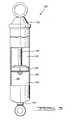
- FIG. 5is a cross-sectional side view of one of the shock absorbers shown in FIG. 4 incorporating the rheological restriction in accordance with the present invention.
- FIG. 6is an enlarged view of the piston assembly of the shock absorber shown in FIGS. 4 and 5 .
- FIGS. 1-3a controlled hydraulic restriction in accordance with the present invention and which is designated generally by reference numeral 10 .
- Hydraulic restriction 10is formed by a housing 12 which defines a first chamber 14 and a second chamber 16 . Hydraulic restriction 10 is disposed between first chamber 14 and second chamber 16 to control the flow of fluid between the two chambers.
- a first filter 20Disposed within hydraulic restriction 10 are a first filter 20 , a second filter 22 and a plurality of particles 24 .
- Filters 20 and 22have a filtration grade below the size of particles 24 but they do allow the flow of fluid between chambers 14 and 16 .
- the fluid within first chamber 14is free of particles 24
- the fluid within hydraulic restriction 10includes the plurality of particles 24
- the fluid within chamber 16is free of particles 24 .
- Particles 24are either dielectric particles which create an electro-rheological fluid between filters 20 and 22 or particles 24 are micron-sized magnetizable particles which create a magneto-rheological fluid between filters 20 and 22 .
- Electro-rheological fluidsare dispersions of dielectric particles in an electrically insulating oil.
- the dielectric particlesare so-called dispersed phase and the insulating oil is so-called a dispersion medium.
- the electro-rheological dispersionwill behave as shown in FIG. 1 .
- Particles 24will be located adjacent one of the two filters 20 and 22 depending on the direction of fluid flow. With particles 24 located adjacent to one of the two filters 20 and 22 , the fluid flow through restriction 10 will be highly limited.
- the dispersed particlesare electrically polarized. The polarized particles attract each other due to the electrostatic interaction. Consequently, particle cluster chains form between the electrodes 30 and 32 as shown in FIG.
- Magneto-rheological fluidsare suspensions of micron-sized, magnetizable particles in an oil. When there is no magnetic field applied, the magneto-rheological suspension will behave as shown in FIG. 1 . Particles 24 will be located adjacent one of the two filters 20 and 22 depending on the direction of fluid flow. With particles 24 located adjacent to one of the two filters 20 and 22 , the fluid flow through hydraulic restriction 10 will be highly limited. When a magnetic field is applied in the direction of fluid flow, the suspended particles are magnetically polarized. The polarized particles attract each other due to the magnetic interaction. Consequently, particle cluster chains form between the magnetic poles 40 and 42 as shown in FIG. 2 . With particles 24 clustered as shown in FIG. 2, fluid flow through hydraulic restriction 10 will be less restrictive.
- FIG. 4there is shown a schematic representation of a vehicle 110 incorporating the rheological controlled hydraulic restriction in accordance with the present invention. While the present invention is illustrated in the drawings as being associated with an automotive vehicle, it is within the scope of the present invention to incorporate the rheological controlled hydraulic restriction of the present invention in other types of vehicles.
- shock absorberrefers to shock absorbers in the general sense of the phrase and thus, it includes MacPherson struts as well as other damping devices.
- Vehicle 110includes a body 112 , a rear suspension assembly 114 and a front suspension system 116 .
- Rear suspension assembly 114is a transversely extending rear suspension assembly adapted to operatively support a pair of rear wheels 118 .
- Rear suspension assembly 114is operatively connected to body 112 by means of a pair of shock absorbers 120 as well as a pair of springs 122 .
- Front suspension system 116includes a transversely extending rear suspension assembly adapted to operatively support a pair of front wheels 124 .
- Front suspension system 116is operatively connected to body 112 by means of a pair of shock absorbers 126 , as well as by another pair of springs 128 .
- Shock absorbers 120 and 126serve to dampen the relative motion of the unsprung portion (front suspensions assembly 116 and rear suspension assembly 114 ) and the sprung portion (body 112 ) of vehicle 110 .
- shock absorber 120is shown in greater detail. While FIG. 5 illustrates shock absorber 120 , it is to be understood that shock absorber 126 also includes the rheological controlled hydraulic restriction in accordance with the present invention. Shock absorber 126 differs than shock absorber 120 in the way in which it is adapted for assembly into vehicle 110 . Shock absorber 120 comprises a pressure tube 140 , a piston assembly 142 and a piston rod 144 .
- Pressure tube 140defines a working chamber 146 .
- Piston assembly 142is slidably disposed within pressure tube 140 and it divides pressure tube 140 into an upper working chamber 148 and a lower working chamber 150 .
- a sealis typically disposed between piston assembly 142 and pressure tube 140 to permit sliding movement of piston assembly 142 without generating undue frictional forces as well as sealing upper working chamber 148 from lower working chamber 150 .
- Piston rod 144is attached to piston assembly 142 and it extends through upper working chamber 148 and through an upper end cap 152 which closes the upper end of pressure tube 140 .
- a sealing system associated with upper end cap 152seals the interface between upper end cap 152 and piston rod 144 .
- Pressure tube 140is filled with hydraulic oil and it includes an end cap 154 for attachment to the unsprung portion of vehicle 110 .
- the hydraulic oil disposed within pressure tube 140is compatible with particles 24 whether particles 24 create an electro-rheological fluid or if particles 24 create a magneto-rheological fluid.
- Suspension movement of vehicle 110will cause extension or compression movements of piston assembly 142 with respect to pressure tube 140 .
- hydraulic oilmust flow between upper and lower working chambers 148 and 150 .
- Shock absorber 120generates damping forces by controlling the amount of fluid flow between chambers 148 and 150 .
- Piston assembly 142includes a piston body 156 which defines at least one compression fluid passage 160 and at least one extension fluid passage 162 .
- a compression valve assembly 164permits fluid flow through passage 160 during a compression stroke of shock absorber 120 and prohibits fluid flow through passage 160 during an extension stroke of shock absorber 120 .
- An extension valve assembly 166permits fluid flow through passage 162 during an extension stroke of shock absorber 120 and prohibits fluid flow through passage 162 during a compression stroke of shock absorber 120 .
- Passages 160 and 162each incorporate a respective rheological controlled hydraulic restriction 10 .
- Piston body 156serves as housing 12
- upper working chamber 148serves as first chamber 14
- lower working chamber 150serves as second chamber 16 for hydraulic restriction 10 .
- First filter 20 , second filter 22 and particles 24are disposed within each of passages 160 and 162 .
- Electrodes 30 - 36are incorporated into shock absorber 120 if particles 24 are electro-rheological controlled particles or magnetic poles 40 - 46 are incorporated into shock absorber 120 if particles 24 are magneto-rheological controlled particles.
- Extension valve assembly 166prohibits fluid flow through extension fluid passage 162 and thus, all fluid flow between chambers 148 and 150 will be through compression fluid passage 160 .
- the rate of fluid flow through passage 160will be determined by rheological controlled hydraulic restriction 10 disposed within passage 160 . If no electric or magnetic field is applied, a highly restricted fluid flow will be created by hydraulic restriction 10 and thus, a firm ride or high damping load will be provided by shock absorber 120 (FIG. 1 ).
- shock absorber 120If an electric or magnetic field is applied by electrodes 30 and 32 or magnetic poles 40 and 42 , a low restricted fluid flow will be created by hydraulic restriction 10 and thus, a soft ride or low damping load will be provided by shock absorber 120 (FIG. 2 ). If an electric or magnetic field is applied by electrodes 34 and 36 or magnetic poles 44 and 46 , an intermediate restricted fluid flow will be created by hydraulic restriction 10 and thus, an intermediate rid or an intermediate damping load will be provided by shock absorber 120 (FIG. 2 ).
- shock absorber 120If an electric or magnetic field is applied by electrodes 30 and 32 or magnetic poles 40 and 42 , a low restricted fluid flow will be created by hydraulic restriction 10 and thus, a soft ride or low damping load will be provided by shock absorber 120 (FIG. 2 ). If an electric or magnetic field is applied by electrodes 34 and 36 or magnetic poles 44 and 46 , an intermediate restricted fluid flow will be created by hydraulic restriction 10 and thus, an intermediate rid or an intermediate damping load will be provided by shock absorber 120 (FIG. 2 ).
- the damping characteristics for shock absorber 120can be controlled to be firm, soft or intermediate in both the compression and extension movements for shock absorber 120 .
- shock absorberWhile the above detailed description utilized a mono-tube design for the shock absorber, it is within the scope of the present invention to incorporate hydraulic restrictions 10 into dual tube shock absorbers, bypass flow shock absorbers (both internal and external to the tubes of the shock absorber) as well as other designs for dampers that are known in the art. Also, while the present invention is described as being incorporated into a shock absorber, the present invention is not limited to shock absorber applications, but it can be utilized with applications that include a controllable restriction including, but not limited to, all the difference versions of servo valve technology.
Landscapes
- Engineering & Computer Science (AREA)
- General Engineering & Computer Science (AREA)
- Mechanical Engineering (AREA)
- Physics & Mathematics (AREA)
- Electromagnetism (AREA)
- Fluid-Damping Devices (AREA)
- Vehicle Body Suspensions (AREA)
- Fluid-Pressure Circuits (AREA)
Abstract
Description
Claims (22)
Priority Applications (7)
| Application Number | Priority Date | Filing Date | Title |
|---|---|---|---|
| US10/670,667US6802404B1 (en) | 2003-09-25 | 2003-09-25 | Electro-rheological or magneto-rheological controlled hydraulic restriction |
| BRPI0414726-0ABRPI0414726A (en) | 2003-09-25 | 2004-08-23 | controllable restriction and shock absorber |
| DE602004029588TDE602004029588D1 (en) | 2003-09-25 | 2004-08-23 | shock absorber |
| JP2006528003AJP2007506923A (en) | 2003-09-25 | 2004-08-23 | Electrorheological or magnetorheologically controlled hydraulic throttling |
| CNB2004800280276ACN100526675C (en) | 2003-09-25 | 2004-08-23 | Electro-rheological or magneto-rheological controlled hydraulic restriction |
| EP04781856AEP1664585B1 (en) | 2003-09-25 | 2004-08-23 | Shock absorber |
| PCT/US2004/027251WO2005036021A1 (en) | 2003-09-25 | 2004-08-23 | Electro-rheological or magneto-rheological controlled hydraulic restriction |
Applications Claiming Priority (1)
| Application Number | Priority Date | Filing Date | Title |
|---|---|---|---|
| US10/670,667US6802404B1 (en) | 2003-09-25 | 2003-09-25 | Electro-rheological or magneto-rheological controlled hydraulic restriction |
Publications (1)
| Publication Number | Publication Date |
|---|---|
| US6802404B1true US6802404B1 (en) | 2004-10-12 |
Family
ID=33098484
Family Applications (1)
| Application Number | Title | Priority Date | Filing Date |
|---|---|---|---|
| US10/670,667Expired - Fee RelatedUS6802404B1 (en) | 2003-09-25 | 2003-09-25 | Electro-rheological or magneto-rheological controlled hydraulic restriction |
Country Status (7)
| Country | Link |
|---|---|
| US (1) | US6802404B1 (en) |
| EP (1) | EP1664585B1 (en) |
| JP (1) | JP2007506923A (en) |
| CN (1) | CN100526675C (en) |
| BR (1) | BRPI0414726A (en) |
| DE (1) | DE602004029588D1 (en) |
| WO (1) | WO2005036021A1 (en) |
Cited By (7)
| Publication number | Priority date | Publication date | Assignee | Title |
|---|---|---|---|---|
| WO2007149393A3 (en)* | 2006-06-16 | 2008-01-31 | Univ Maryland | System and method for magnetorheological-fluid damping utilizing porous media |
| US20080053763A1 (en)* | 2006-08-31 | 2008-03-06 | Norman Wereley | System and method for self-powered magnetorheological-fluid damping |
| CN100425860C (en)* | 2004-12-11 | 2008-10-15 | 尹学军 | Damper |
| CN101245820B (en)* | 2004-12-11 | 2010-06-02 | 尹学军 | Damper |
| CN101245821B (en)* | 2004-12-11 | 2011-03-23 | 尹学军 | Damper with axial guiding device |
| CN102168736A (en)* | 2011-05-05 | 2011-08-31 | 天津大学 | Magnetorheological torsional vibration damper for engine |
| CN115325077A (en)* | 2022-07-26 | 2022-11-11 | 四川宁江山川机械有限责任公司 | Piston valve of shock absorber |
Families Citing this family (6)
| Publication number | Priority date | Publication date | Assignee | Title |
|---|---|---|---|---|
| JP4914749B2 (en)* | 2007-03-30 | 2012-04-11 | 本田技研工業株式会社 | Variable damping force damper |
| CN102112776B (en)* | 2008-06-02 | 2014-10-29 | 洛德公司 | Magnetorheological fluid damper with increased opening yield strength |
| DE102009001546A1 (en)* | 2009-03-13 | 2010-09-16 | Deere & Company, Moline | Suspension device for a motor vehicle |
| DE102011109291B4 (en) | 2011-08-03 | 2013-02-28 | Schneider GmbH & Co. Produktions- und Vertriebs-KG | control valve |
| KR101308545B1 (en) | 2011-11-02 | 2013-09-13 | 인하대학교 산학협력단 | A flow-type valve mechanism of base oil using ER and MR fluid |
| US11073190B2 (en)* | 2016-12-26 | 2021-07-27 | Hitachi Astemo, Ltd. | Cylinder apparatus |
Citations (14)
| Publication number | Priority date | Publication date | Assignee | Title |
|---|---|---|---|---|
| US4255166A (en)* | 1979-07-31 | 1981-03-10 | Exxon Research And Engineering Company | Process for the removal of particulates entrained in a fluid using a magnetically stabilized fluid cross-flow contactor |
| US4351515A (en)* | 1979-07-02 | 1982-09-28 | Toyota Jidosha Kogyo Kabushiki Kaisha | Feedback control type shock absorbing suspension system |
| US5014829A (en) | 1989-04-18 | 1991-05-14 | Hare Sr Nicholas S | Electro-rheological shock absorber |
| US5161653A (en) | 1989-04-18 | 1992-11-10 | Hare Sr Nicholas S | Electro-rheological shock absorber |
| US5277281A (en) | 1992-06-18 | 1994-01-11 | Lord Corporation | Magnetorheological fluid dampers |
| US5518613A (en)* | 1994-12-14 | 1996-05-21 | Harrison First International, Inc. | Portable water purifying and drinking device |
| US5829319A (en) | 1996-10-04 | 1998-11-03 | Vibratech, Inc. | Magneto-rheological torsional vibration damper |
| US5891356A (en) | 1990-08-30 | 1999-04-06 | Asahi Kasei Kogyo Kabushiki Kaisha | Homogeneous electrorheological fluid |
| US5894000A (en) | 1992-09-30 | 1999-04-13 | The United States Of America As Represented By The Secratary Of The Navy | Electro-rheological fluid composition having polymeric sponge particulates |
| US5956951A (en) | 1996-09-20 | 1999-09-28 | Mr Technologies | Adjustable magneto-rheological fluid device |
| US5985168A (en) | 1997-09-29 | 1999-11-16 | University Of Pittsburgh Of The Commonwealth System Of Higher Education | Magnetorheological fluid |
| US6065572A (en)* | 1995-11-13 | 2000-05-23 | The Lubrizol Corporation | Polymeric materials to self-regulate the level of polar activators in electrorheological fluids |
| US6436170B1 (en)* | 2000-06-23 | 2002-08-20 | Air Products And Chemical, Inc. | Process and apparatus for removing particles from high purity gas systems |
| US6508991B2 (en)* | 2001-03-16 | 2003-01-21 | Global Environmental Concepts, Llc | Emission control device and method |
Family Cites Families (5)
| Publication number | Priority date | Publication date | Assignee | Title |
|---|---|---|---|---|
| GB1543865A (en)* | 1977-04-26 | 1979-04-11 | Ni Labor Fiz Khim Skoi Mekh Ma | Dispensing of flowable materials |
| DE2758072A1 (en)* | 1977-12-24 | 1979-07-05 | Teves Gmbh Alfred | Rapid response solenoid valve - has magnetisable particles in valve chamber to block flow through outlet formed by screen-like plate |
| US4709907A (en)* | 1986-01-30 | 1987-12-01 | Thorn Richard P | Quiet fluid filled vibration isolator |
| JP3778251B2 (en)* | 1999-11-05 | 2006-05-24 | 株式会社荏原製作所 | Micro valve |
| JP2003158883A (en) | 2001-11-16 | 2003-05-30 | Makoto Morishita | Functional element, and flow-variable valve using the same |
- 2003
- 2003-09-25USUS10/670,667patent/US6802404B1/ennot_activeExpired - Fee Related
- 2004
- 2004-08-23WOPCT/US2004/027251patent/WO2005036021A1/enactiveApplication Filing
- 2004-08-23JPJP2006528003Apatent/JP2007506923A/enactivePending
- 2004-08-23BRBRPI0414726-0Apatent/BRPI0414726A/ennot_activeIP Right Cessation
- 2004-08-23CNCNB2004800280276Apatent/CN100526675C/ennot_activeExpired - Fee Related
- 2004-08-23DEDE602004029588Tpatent/DE602004029588D1/ennot_activeExpired - Lifetime
- 2004-08-23EPEP04781856Apatent/EP1664585B1/ennot_activeExpired - Lifetime
Patent Citations (14)
| Publication number | Priority date | Publication date | Assignee | Title |
|---|---|---|---|---|
| US4351515A (en)* | 1979-07-02 | 1982-09-28 | Toyota Jidosha Kogyo Kabushiki Kaisha | Feedback control type shock absorbing suspension system |
| US4255166A (en)* | 1979-07-31 | 1981-03-10 | Exxon Research And Engineering Company | Process for the removal of particulates entrained in a fluid using a magnetically stabilized fluid cross-flow contactor |
| US5014829A (en) | 1989-04-18 | 1991-05-14 | Hare Sr Nicholas S | Electro-rheological shock absorber |
| US5161653A (en) | 1989-04-18 | 1992-11-10 | Hare Sr Nicholas S | Electro-rheological shock absorber |
| US5891356A (en) | 1990-08-30 | 1999-04-06 | Asahi Kasei Kogyo Kabushiki Kaisha | Homogeneous electrorheological fluid |
| US5277281A (en) | 1992-06-18 | 1994-01-11 | Lord Corporation | Magnetorheological fluid dampers |
| US5894000A (en) | 1992-09-30 | 1999-04-13 | The United States Of America As Represented By The Secratary Of The Navy | Electro-rheological fluid composition having polymeric sponge particulates |
| US5518613A (en)* | 1994-12-14 | 1996-05-21 | Harrison First International, Inc. | Portable water purifying and drinking device |
| US6065572A (en)* | 1995-11-13 | 2000-05-23 | The Lubrizol Corporation | Polymeric materials to self-regulate the level of polar activators in electrorheological fluids |
| US5956951A (en) | 1996-09-20 | 1999-09-28 | Mr Technologies | Adjustable magneto-rheological fluid device |
| US5829319A (en) | 1996-10-04 | 1998-11-03 | Vibratech, Inc. | Magneto-rheological torsional vibration damper |
| US5985168A (en) | 1997-09-29 | 1999-11-16 | University Of Pittsburgh Of The Commonwealth System Of Higher Education | Magnetorheological fluid |
| US6436170B1 (en)* | 2000-06-23 | 2002-08-20 | Air Products And Chemical, Inc. | Process and apparatus for removing particles from high purity gas systems |
| US6508991B2 (en)* | 2001-03-16 | 2003-01-21 | Global Environmental Concepts, Llc | Emission control device and method |
Cited By (10)
| Publication number | Priority date | Publication date | Assignee | Title |
|---|---|---|---|---|
| CN100425860C (en)* | 2004-12-11 | 2008-10-15 | 尹学军 | Damper |
| CN101245820B (en)* | 2004-12-11 | 2010-06-02 | 尹学军 | Damper |
| CN101245821B (en)* | 2004-12-11 | 2011-03-23 | 尹学军 | Damper with axial guiding device |
| WO2007149393A3 (en)* | 2006-06-16 | 2008-01-31 | Univ Maryland | System and method for magnetorheological-fluid damping utilizing porous media |
| US20080023278A1 (en)* | 2006-06-16 | 2008-01-31 | University Of Maryland | System and method for magnetorheological-fluid damping utilizing porous media |
| US7874407B2 (en)* | 2006-06-16 | 2011-01-25 | University Of Maryland | System and method for magnetorheological-fluid damping utilizing porous media |
| US20080053763A1 (en)* | 2006-08-31 | 2008-03-06 | Norman Wereley | System and method for self-powered magnetorheological-fluid damping |
| CN102168736A (en)* | 2011-05-05 | 2011-08-31 | 天津大学 | Magnetorheological torsional vibration damper for engine |
| CN102168736B (en)* | 2011-05-05 | 2012-07-11 | 天津大学 | Engine Magnetorheological Torsional Vibration Absorber |
| CN115325077A (en)* | 2022-07-26 | 2022-11-11 | 四川宁江山川机械有限责任公司 | Piston valve of shock absorber |
Also Published As
| Publication number | Publication date |
|---|---|
| BRPI0414726A (en) | 2006-11-21 |
| WO2005036021A1 (en) | 2005-04-21 |
| DE602004029588D1 (en) | 2010-11-25 |
| JP2007506923A (en) | 2007-03-22 |
| CN1860313A (en) | 2006-11-08 |
| EP1664585B1 (en) | 2010-10-13 |
| EP1664585A1 (en) | 2006-06-07 |
| EP1664585A4 (en) | 2007-02-28 |
| CN100526675C (en) | 2009-08-12 |
Similar Documents
| Publication | Publication Date | Title |
|---|---|---|
| US7216747B2 (en) | Amplitude controlled orifice valving | |
| US6776269B1 (en) | Twin piston shock absorber | |
| US6220409B1 (en) | Stroke dependent bypass | |
| US6460664B1 (en) | Independently tunable variable bleed orifice | |
| EP1664578B1 (en) | Stroke dependent bypass | |
| US7950506B2 (en) | Semi third tube design | |
| US9586456B2 (en) | Recuperating passive and active suspension | |
| EP2158416B1 (en) | Junction bleed | |
| EP3039312B1 (en) | Shock absorber with frequency dependent passive valve | |
| US9080634B2 (en) | Shock absorber with frequency dependent passive valve | |
| US6802404B1 (en) | Electro-rheological or magneto-rheological controlled hydraulic restriction | |
| US6382372B1 (en) | Ported disc variable bleed orifice | |
| EP1167810B1 (en) | Shock absorber having ported plate low speed tunability | |
| US6644445B2 (en) | Floating port blocker | |
| US11236799B2 (en) | Valve assembly for a damper |
Legal Events
| Date | Code | Title | Description |
|---|---|---|---|
| AS | Assignment | Owner name:TENNECO AUTOMOTIVE OPERATING COMPANY INC., ILLINOI Free format text:ASSIGNMENT OF ASSIGNORS INTEREST;ASSIGNORS:SCHURMANS, RUDI;MAES, MARIO;HOLIVIERS, DAVID;REEL/FRAME:014551/0324;SIGNING DATES FROM 20030901 TO 20030917 | |
| AS | Assignment | Owner name:WACHOVIA BANK, NATIONAL ASSOCIATION, AS COLLATERAL Free format text:AMENDMENT;ASSIGNORS:TENNECO AUTOMOTIVE INC.;TENNECO AUTOMOTIVE OPERATING COMPANY INC.;TENNECO INTERNATIONAL HOLDING CORP.;AND OTHERS;REEL/FRAME:015023/0502 Effective date:20031212 | |
| AS | Assignment | Owner name:JPMORGAN CHASE BANK, AS ADMINISTRATIVE AGENT, TEXA Free format text:SECURITY INTEREST;ASSIGNOR:TENNECO AUTOMOTIVE INC.;REEL/FRAME:014421/0639 Effective date:20040123 | |
| FEPP | Fee payment procedure | Free format text:PAYOR NUMBER ASSIGNED (ORIGINAL EVENT CODE: ASPN); ENTITY STATUS OF PATENT OWNER: LARGE ENTITY | |
| AS | Assignment | Owner name:WACHOVIA BANK, NATIONAL ASSOCIATION, AS COLLATERAL Free format text:AMENDMENT TO SECURITY INTEREST IN UNITED STATES PATENTS;ASSIGNORS:TENNECO AUTOMOTIVE INC.;TENNECO AUTOMOTIVE OPERATING COMPANY INC.;TENNECO INTERNATIONAL HOLDING CORP.;AND OTHERS;REEL/FRAME:015953/0848 Effective date:20050428 | |
| AS | Assignment | Owner name:JPMORGAN CHASE BANK,NEW YORK Free format text:AMENDMENT TO SECURITY INTEREST IN UNITED STATES PATENTS;ASSIGNORS:TENNECO AUTOMOTIVE OPERATING COMPANY INC.;TENNECO INTERNATIONAL HOLDING CORP.;TENNECO GLOBAL HOLDINGS INC.;AND OTHERS;REEL/FRAME:019009/0247 Effective date:20070312 Owner name:JPMORGAN CHASE BANK, NEW YORK Free format text:AMENDMENT TO SECURITY INTEREST IN UNITED STATES PATENTS;ASSIGNORS:TENNECO AUTOMOTIVE OPERATING COMPANY INC.;TENNECO INTERNATIONAL HOLDING CORP.;TENNECO GLOBAL HOLDINGS INC.;AND OTHERS;REEL/FRAME:019009/0247 Effective date:20070312 | |
| FPAY | Fee payment | Year of fee payment:4 | |
| AS | Assignment | Owner name:THE PULLMAN COMPANY, ILLINOIS Free format text:RELEASE OF AMENDMENT TO SECURITY INTEREST;ASSIGNOR:U.S. BANK NATIONAL ASSOCIATION (AS SUCCESSOR IN INTEREST TO WACHOVIA BANK, NATIONAL ASSOCIATION);REEL/FRAME:024996/0726 Effective date:20100902 Owner name:TENNECO INTERNATIONAL HOLDING CORP., ILLINOIS Free format text:RELEASE OF AMENDMENT TO SECURITY INTEREST;ASSIGNOR:U.S. BANK NATIONAL ASSOCIATION (AS SUCCESSOR IN INTEREST TO WACHOVIA BANK, NATIONAL ASSOCIATION);REEL/FRAME:024996/0726 Effective date:20100902 Owner name:CLEVITE INDUSTRIES INC., ILLINOIS Free format text:RELEASE OF AMENDMENT TO SECURITY INTEREST;ASSIGNOR:U.S. BANK NATIONAL ASSOCIATION (AS SUCCESSOR IN INTEREST TO WACHOVIA BANK, NATIONAL ASSOCIATION);REEL/FRAME:024996/0726 Effective date:20100902 Owner name:TENNECO AUTOMOTIVE INC. (NOW KNOWN AS TENNECO INC. Free format text:RELEASE OF AMENDMENT TO SECURITY INTEREST;ASSIGNOR:U.S. BANK NATIONAL ASSOCIATION (AS SUCCESSOR IN INTEREST TO WACHOVIA BANK, NATIONAL ASSOCIATION);REEL/FRAME:024996/0726 Effective date:20100902 Owner name:TMC TEXAS INC., ILLINOIS Free format text:RELEASE OF AMENDMENT TO SECURITY INTEREST;ASSIGNOR:U.S. BANK NATIONAL ASSOCIATION (AS SUCCESSOR IN INTEREST TO WACHOVIA BANK, NATIONAL ASSOCIATION);REEL/FRAME:024996/0726 Effective date:20100902 Owner name:TENNECO GLOBAL HOLDINGS INC., ILLINOIS Free format text:RELEASE OF AMENDMENT TO SECURITY INTEREST;ASSIGNOR:U.S. BANK NATIONAL ASSOCIATION (AS SUCCESSOR IN INTEREST TO WACHOVIA BANK, NATIONAL ASSOCIATION);REEL/FRAME:024996/0726 Effective date:20100902 Owner name:TENNECO AUTOMOTIVE OPERATING COMPANY INC., ILLINOI Free format text:RELEASE OF AMENDMENT TO SECURITY INTEREST;ASSIGNOR:U.S. BANK NATIONAL ASSOCIATION (AS SUCCESSOR IN INTEREST TO WACHOVIA BANK, NATIONAL ASSOCIATION);REEL/FRAME:024996/0726 Effective date:20100902 | |
| REMI | Maintenance fee reminder mailed | ||
| LAPS | Lapse for failure to pay maintenance fees | ||
| STCH | Information on status: patent discontinuation | Free format text:PATENT EXPIRED DUE TO NONPAYMENT OF MAINTENANCE FEES UNDER 37 CFR 1.362 | |
| FP | Lapsed due to failure to pay maintenance fee | Effective date:20121012 | |
| AS | Assignment | Owner name:TENNECO GLOBAL HOLDINGS INC., ILLINOIS Free format text:CONFIRMATION OF TERMINATION AND RELEASE OF SECURITY INTEREST IN PATENT RIGHTS (R/F 19009/0247);ASSIGNOR:JPMORGAN CHASE BANK, N.A., AS ADMINISTRATIVE AGENT;REEL/FRAME:055429/0284 Effective date:20210226 Owner name:TENNECO INTERNATIONAL HOLDING CORP., ILLINOIS Free format text:CONFIRMATION OF TERMINATION AND RELEASE OF SECURITY INTEREST IN PATENT RIGHTS (R/F 19009/0247);ASSIGNOR:JPMORGAN CHASE BANK, N.A., AS ADMINISTRATIVE AGENT;REEL/FRAME:055429/0284 Effective date:20210226 Owner name:TENNECO AUTOMOTIVE OPERATING COMPANY INC., ILLINOIS Free format text:CONFIRMATION OF TERMINATION AND RELEASE OF SECURITY INTEREST IN PATENT RIGHTS (R/F 19009/0247);ASSIGNOR:JPMORGAN CHASE BANK, N.A., AS ADMINISTRATIVE AGENT;REEL/FRAME:055429/0284 Effective date:20210226 Owner name:CLEVITE INDUSTRIES INC., ILLINOIS Free format text:CONFIRMATION OF TERMINATION AND RELEASE OF SECURITY INTEREST IN PATENT RIGHTS (R/F 19009/0247);ASSIGNOR:JPMORGAN CHASE BANK, N.A., AS ADMINISTRATIVE AGENT;REEL/FRAME:055429/0284 Effective date:20210226 Owner name:TMC TEXAS INC., ILLINOIS Free format text:CONFIRMATION OF TERMINATION AND RELEASE OF SECURITY INTEREST IN PATENT RIGHTS (R/F 19009/0247);ASSIGNOR:JPMORGAN CHASE BANK, N.A., AS ADMINISTRATIVE AGENT;REEL/FRAME:055429/0284 Effective date:20210226 Owner name:TENNECO INC. (FORMERLY KNOWN AS TENNECO AUTOMOTIVE INC.), ILLINOIS Free format text:CONFIRMATION OF TERMINATION AND RELEASE OF SECURITY INTEREST IN PATENT RIGHTS (R/F 19009/0247);ASSIGNOR:JPMORGAN CHASE BANK, N.A., AS ADMINISTRATIVE AGENT;REEL/FRAME:055429/0284 Effective date:20210226 Owner name:THE PULLMAN COMPANY, ILLINOIS Free format text:CONFIRMATION OF TERMINATION AND RELEASE OF SECURITY INTEREST IN PATENT RIGHTS (R/F 19009/0247);ASSIGNOR:JPMORGAN CHASE BANK, N.A., AS ADMINISTRATIVE AGENT;REEL/FRAME:055429/0284 Effective date:20210226 |