US6801564B2 - Reverse link correlation filter in wireless communication systems - Google Patents
Reverse link correlation filter in wireless communication systemsDownload PDFInfo
- Publication number
- US6801564B2 US6801564B2US09/738,934US73893400AUS6801564B2US 6801564 B2US6801564 B2US 6801564B2US 73893400 AUS73893400 AUS 73893400AUS 6801564 B2US6801564 B2US 6801564B2
- Authority
- US
- United States
- Prior art keywords
- data
- information
- pilot
- correlation
- correlation filter
- Prior art date
- Legal status (The legal status is an assumption and is not a legal conclusion. Google has not performed a legal analysis and makes no representation as to the accuracy of the status listed.)
- Expired - Lifetime, expires
Links
Images


Classifications
- H—ELECTRICITY
- H04—ELECTRIC COMMUNICATION TECHNIQUE
- H04B—TRANSMISSION
- H04B1/00—Details of transmission systems, not covered by a single one of groups H04B3/00 - H04B13/00; Details of transmission systems not characterised by the medium used for transmission
- H04B1/69—Spread spectrum techniques
- H04B1/707—Spread spectrum techniques using direct sequence modulation
- H04B1/7097—Interference-related aspects
- H04B1/7103—Interference-related aspects the interference being multiple access interference
- H04B1/7105—Joint detection techniques, e.g. linear detectors
- H—ELECTRICITY
- H04—ELECTRIC COMMUNICATION TECHNIQUE
- H04B—TRANSMISSION
- H04B1/00—Details of transmission systems, not covered by a single one of groups H04B3/00 - H04B13/00; Details of transmission systems not characterised by the medium used for transmission
- H04B1/69—Spread spectrum techniques
- H04B1/707—Spread spectrum techniques using direct sequence modulation
- H04B1/7097—Interference-related aspects
- H04B1/711—Interference-related aspects the interference being multi-path interference
- H04B1/7115—Constructive combining of multi-path signals, i.e. RAKE receivers
- H04B1/712—Weighting of fingers for combining, e.g. amplitude control or phase rotation using an inner loop
- H—ELECTRICITY
- H04—ELECTRIC COMMUNICATION TECHNIQUE
- H04B—TRANSMISSION
- H04B2201/00—Indexing scheme relating to details of transmission systems not covered by a single group of H04B3/00 - H04B13/00
- H04B2201/69—Orthogonal indexing scheme relating to spread spectrum techniques in general
- H04B2201/707—Orthogonal indexing scheme relating to spread spectrum techniques in general relating to direct sequence modulation
- H04B2201/70703—Orthogonal indexing scheme relating to spread spectrum techniques in general relating to direct sequence modulation using multiple or variable rates
- H04B2201/70705—Rate detection
- H—ELECTRICITY
- H04—ELECTRIC COMMUNICATION TECHNIQUE
- H04B—TRANSMISSION
- H04B2201/00—Indexing scheme relating to details of transmission systems not covered by a single group of H04B3/00 - H04B13/00
- H04B2201/69—Orthogonal indexing scheme relating to spread spectrum techniques in general
- H04B2201/707—Orthogonal indexing scheme relating to spread spectrum techniques in general relating to direct sequence modulation
- H04B2201/70707—Efficiency-related aspects
- H04B2201/7071—Efficiency-related aspects with dynamic control of receiver resources
Definitions
- the present inventionrelates to a code division multiple access (CDMA) communication system and, more particularly to a receiver having a correlation filter in such a CDMA communication system.
- CDMAcode division multiple access
- CDMA modulationwhich is known in the art, is a multi-user access transmission scheme in which signals from different users overlap 20 both in frequency and in time. This is in contrast to Frequency Division Multiple Access (FDMA), also known in the art, in which user signals overlap in time, but are assigned unique frequencies, and Time Division Multiple Access (TDMA) in which user signals overlap in frequency, but are assigned unique time slots.
- FDMAFrequency Division Multiple Access
- TDMATime Division Multiple Access
- CDMA signalingis frequently used in cellular communication systems between a base station (BS) within a cell and a plurality of mobile stations (MS) in the possession of users within the cell.
- the CDMA transmitted signal for each user that broadcast from the user's mobile station (MS)is spread over a wide bandwidth, which is greater than the initial user information bandwidth.
- Each user's signalis spread by a different spreading code to create a wideband spread. All of the spread wideband signals transmitted by the different users are received at the base station (BS) and form a composite received signal.
- the receiver at the base station (BS)distinguishes different users by using a local copy (or local reference) of the spreading code, which is available to both the mobile stations and the base station in the CDMA system. Such a process is called channelization.
- channelization in the reverse linkie., when a mobile station (MS) is transmitting to a base station (BS) in the system, is accomplished using a wideband code called a pseudorandom noise (PN) code, also known in the art.
- PNpseudorandom noise
- the receiver at the base station (BS)sifts the desired signal from a particular user out of the composite signal by correlating, i.e., using a correlation filter (CF), on the composite signal with the original wideband code. All other signals having codes that do not match the code for the desired user code are rejected.
- BSbase station
- CFcorrelation filter
- An exemplary CDMA wireless systemincludes a plurality of data channels, e.g., the access and traffic channels (and more channels depending on the design of the CDMA system).
- the traffic channelis used to transmit user data and voice, as well as signaling messages.
- the access channelis used by the mobile station (MS), e.g., a cellular phone, to communicate control information with the base station (BS) in the wireless system when the MS does not have a traffic channel assigned.
- the MSuses the access channel to make call originations and to respond to pages and orders.
- These data channels in the CDMA systemhave different functions and data rates.
- a receiver in the MS designed to accommodate data transmission in the different channelsrequires various types of correlation filter (CF) and digital signal processing (DSP) designs for different data rates. Such requirements contribute to the complexity and increase the cost of the receiver design.
- CFcorrelation filter
- DSPdigital signal processing
- a wireless systemis particularly needed that provides a single correlation filter (CF) in the receiver which can be used in receiving data in all data channels.
- CFcorrelation filter
- the inventionrelates to a reverse link receiver in wireless systems and a correlation filter thereof.
- a transmitter and a receiverare provided in the reverse link of a wireless system according to the invention.
- the receiverincludes (1) a field programmable gate array (FPGA) which comprises a pseudorandom noise (PN) code generator, (2) a pilot post processor, (3) a data post processor (4) a correlation filter (CF), and (5) a digital signal processor (DSP).
- FPGAfield programmable gate array
- the correlation filter (CF)comprises a (correlating filter) CF core for processing data in the three channels, namely the access, maintenance and traffic channels.
- the DSPis used to control and post-process the outputs of the field programmable gate array FPGA.
- a mode controller in the DSPcontrols the channel selection (from the access, maintenance and traffic channels) and the channel symbol mode (data and/or pilot).
- the pilot post processor and data post processor in the FPGAin conjunction with the DSP, provide pilot symbol aided QPSK demodulation of up to 3 multipaths received at the receiver.
- QPSK modulationis a modulation technique that allows the transmission of two bits of information in each symbol period.
- QPSK modulationmakes use of the quadrature component I in addition to the in-phase component Q of a symbol in the frame being transmitted from the transmitter to the receiver.
- the I and Q componentsare typically viewed as the real and imaginary parts of a complex signal being transmitted in the channels of the CDMA system.
- the in-phase component, I, and the quadrature component, Qcan be combined without interfering with each other (i.e., they are orthogonal to each other) which doubles the bandwidth efficiency in comparison with simply transmitting one bit of information in a symbol period.
- the CF coreuses time multiplexing to provide pilot symbol correlation at the three data or chip rates (tiers 1, 2 and 3).
- a chipis a unit of time which corresponds to the output interval of the PN spreading code. The chip time determines the bandwidth of the CDMA waveform and the chip time divided by the user symbol time determines the spreading factor of the system.
- the sampling period for a chip in CDMA standard IS-95is ⁇ fraction (1/1228800) ⁇ seconds.
- the pilot post processing and data post processing in the FPGAin conjunction with the data post processor and pilot post processor in the DSP, provide QPSK demodulation and recovery of the original data transmitted by the transmitter for all three channels, i.e., the access, maintenance and traffic channels.
- the CF core according to the inventionperforms 8-chip (i.e., tier 1 rate) complex correlation with 64 correlation lags while allowing no data loss as the 64 correlation lags are being processed, where a lag is a time instant for which the PN code is held constant so that outputs can be generated.
- the CF corewhich is an 8-chip correlation engine, is time multiplexed to allow multiple 8-chip correlations to be performed with the same correlation engine.
- the inventionadvantageously provides the ability to generate integer multiples of the 8-chip correlation for larger correlation lengths, e.g., 32 chips (tier 2) or 128 chips (tier 3).
- the CF design according to the inventionin conjunction with the DSP, provides temporal diversity of the data signals by combining CF outputs. Spatial diversity is also achieved by providing a plurality of correlation filters in accordance with the CF design of the invention.
- Diversityis a technique employed to avoid or mitigate the negative effects of fading and interference.
- Diversitygenerally refers to the ability of a communication system to receive data or information via several independently fading channels.
- diversityenhances a receiver's ability to combine or select (or both) data signals arriving from these independently fading channels, thereby enabling (or facilitating) the extraction of data channels.
- a particular type of diversityis temporal or time diversity, where the same data signals transmitted in different multipaths and received at different time points at the receiver provide the diversity needed for combining or selecting the data signals.
- An exemplary diversity techniqueis maximum ratio combining, or MRC, known in the art.
- MRCprovides sequences of weights in the multitude of data channels in the communication system. A sequence of distinct weights is assigned to segments of a data signal being transmitted.
- the inventionadvantageously provides temporal diversity for all the data channels and modes without the necessity of using different correlation filters for different modes or channels.
- Temporal diversityis achieved by providing three outputs from the different multipaths and combining the three outputs into one, e.g., using MRC.
- a single, common correlation filter (CF) designis provided in a wireless system using CDMA.
- a plurality of channels with different data ratesare provided in the wireless system.
- the channels provided in the wireless systeminclude the access channel, the maintenance channel, and the traffic channel in which information (e.g., pilot or data symbols or both) is transmitted at the tier 1, tier 2 and tier 3 rates.
- the data rate for transmitting the informationis programmable by the digital signal processor (DSP).
- DSPdigital signal processor
- a user-unique codesuch as a PN code, is applied to the information being transmitted in the channels of the wireless system.
- the informationis QPSK modulated and transmitted in any one of the channels and at any data rate.
- the transmitted informationis correlated at the smallest data rate (i.e., the tier 1 rate) using time multiplexing in the correlation filter (CF) of the wireless system.
- the correlated informationis then demultiplexed and QPSK-demodulated.
- the demodulated informationis summed at the proper integer multiple of the tier 1 rate to achieve the tier 2 and tier 3 rates if needed.
- the three strongest multipaths(in terms of the received power) are selected in a window or time period for optimal information recovery.
- three outputs from the demodulated informationcan be provided and combined for temporal diversity. Spatial diversity is achieved by providing the single, common correlation filter design in a plurality of receivers in the wireless system. All the process steps according to the invention described herein are advantageously accomplished using a single, common correlation filter (CF) design, which eliminates the need for additional correlators or correlation filters for processing received information having multiple data rates.
- CFcorrelation filter
- FIG. 1is a diagram generally illustrating a transmitter and a receiver in the reverse link in accordance with the invention
- FIG. 2is a diagram illustrating the structure of a frame of data/pilot symbols being transmitted in various channels in an embodiment according to the invention
- FIG. 3is a diagram illustrating a receiver with a field programmable gate array (FPGA) forming a correlation filter (CF) according to the invention
- FIG. 4is a diagram illustrating an exemplary field programmable gate array forming a correlation filter (CF) core for all channels in the wireless system according to the invention
- FIG. 5is a diagram illustrating an exemplary 8-chip correlation with a pseudorandom noise (PN) code according to the invention
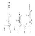
- FIG. 6is a diagram illustrating the pilot post processing of all the channels in an embodiment of the wireless system according to the invention.
- FIG. 6Ashows diagrams illustrating the gain coefficient setting of an accumulating filtering random access memory (AFRAM) and a magnitude accumulating filtering random access memory (MAFRAM) for three different data rates in an embodiment according to the invention
- FIG. 6Bis a diagram illustrating the basic structure of an embodiment of the AFRAM and MAFRAM according to the invention.
- FIG. 7is a diagram illustrating the multipath search processing of multipath response peaks according to the invention.
- FIG. 7Ais a flow diagram illustrating an embodiment of the method of the multipath search processing of multipath response peaks according to the invention.
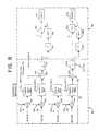
- FIG. 8is a diagram illustrating the data post processing in the channels of the wireless system according to the invention.
- FIG. 9is a flow diagram illustrating an embodiment of the method of QPSK modulation according to the invention.
- transmitter 10is a part of a mobile station (MS) or mobile cellular phone communicating with receiver 20 , Rx 2 , which is part of a base station (BS).
- Digital information at a basic data rateis coded or spread to a transmit data rate (or chip rate) at transmitter 10 .
- a user-unique digital code(the signature or spreading sequence) is applied to the digital information being transmitted, which increases the bandwidth.
- the application of the digital codesuch as a pseudorandom noise (PN) code, typically involves multiplication or logical XOR (exclusive-or) operations on the digital information being transmitted with the PN code.
- PNpseudorandom noise
- the resulting transmitted data sequences or chipsare then QPSK modulated at transmitter 10 to generate an output signal.
- the output signalis added to other similarly processed output signals for multi-channel transmission to the receiver 20 over a communications medium.
- the output signals of multiple usersadvantageously share a single transmission communications frequency, with the multiple signals appearing to be located on top of each other in both the frequency domain and the time domain. Because the applied digital codes are orthogonal and user unique, each output signal transmitted over the shared communications frequency is similarly unique, and can be distinguished from each other through the application of proper processing techniques at receiver 20 .
- the receiver 20comprises a correlation filter CF 3 formed by a field programmable gate array FPGA 5 and a digital signal processor DSP 4 .
- the received signalsare QPSK-demodulated and the appropriate digital code for the user of interest is applied to (i.e., multiplied with) the signal to despread and remove the coding from the desired transmitted signal, and to return it to the basic data rate.
- the digital codei.e., PN code
- This despreading operationeffectively comprises a correlation process comparing the received signal with the appropriate digital code.
- the transmitted data sequences or chipsinclude an in-phase component (I) and a quadrature phase component (Q), which are the real and imaginary parts of a complex signal.
- the despreading operation performed by receiver 20correlates the I and Q components of the received complex signal to the appropriate digital code or signature sequence. This is accomplished using a single correlation filter design (e.g., CF 3 ) for all data rates in the channels of the wireless system.
- the exemplary wireless systemprovides an access channel 11 , a maintenance channel 12 , and a traffic channel 13 in the reverse link.
- the correlation filter CF 3is DSP programmable (i.e., controlled by DSP 4 ) and can be configured to perform the digital signal processing needed in receiving data from any of the three channels 11 , 12 and 13 and at all user data rates. After processing in the correlation filter CF 3 and digital signal processor 4 , the original data from the transmitter 10 , is recovered.
- FIG. 2illustrates the structure of a frame of data/pilot symbols being transmitted in the access, maintenance and traffic channels in an embodiment according to the invention.
- the access channele.g., access channel 11 of FIG. 1
- the access channelprovides a user with a shared data channel for requesting access to the CDMA system.
- the maintenance channele.g., maintenance channel 12 of FIG. 1 maintains the timing of the transmitter and the receiver in the reverse link using a plurality of pilot symbols. No data symbols are transmitted in the maintenance channel.
- the maintenance channelprovides a user with the ability to maintain synchronization with the CDMA system during periods of inactivity.
- User data and signaling messagesi.e., pilot symbols
- the transmitterare transmitted to the receiver Rx 2 in the traffic channel (e.g., traffic channel 13 of FIG. 1 ).
- the wireless systemprovides three tiers of data rates, i.e., tier 1, tier 2 and tier 3, for use by the channels (access channel 11 , maintenance channel 12 , and traffic channel 13 ).
- the transmittertransmits 8 chips per symbol to the receiver.
- the transmittertransmits 32 chips per symbol to the receiver in the reverse link.
- the transmittertransmits 128 chips per symbol in the reverse link of the exemplary wireless system according to the invention. Transmitting data in the access, maintenance and traffic channels is described in further detail below.
- the frameWhen transmitting a frame of data and/or pilot symbols in the reverse link using the access channel, the frame comprises a preamble, succeeded by data, another preamble, and data (FIG. 2 ).
- the frameis modulated using QPSK (quadrature phase shift keying), which is known in the art, and channelized (spread) using a unique digital code, such as a pseudorandom noise (PN) code, also known in the art.
- QPSKquadrature phase shift keying
- PNpseudorandom noise
- a preamble of a frame in the access channelcomprises a plurality of pilot symbols transmitted at the tier 2 rate (i.e., 32 chips per symbol in the frame).
- pilot symbolsonly and no data symbols are transmitted.
- Datawhich succeed the preamble in the frame being transmitted in the access channel, comprise a plurality of data symbols and pilot symbols interleaved at the tier 2 rate (i.e., 32 chips per symbol).
- a mode controller in DSP 4controls the mode of operation of the access channel and switches between the preamble, pilot and data modes.
- the frameWhen transmitting a frame in the maintenance channel, the frame includes information for multiple users denoted P 1 , P 2 , P 3 , . . . , P 128 , and no data which is time division multiplexed (TDM) with two pilot symbols per user.
- the data rateis Tier 3 with 128 chips per symbol (FIG. 2 ). Only one mode of operation is provided in the maintenance channel, namely, the pilot mode.
- a framecomprises pilot and data symbols, where the pilot symbols are placed at periodic intervals between the data symbols.
- the data and pilot symbolsmay be transmitted at any data rate; transmission at tier 1 rate (i.e., 8 chips per symbol), tier 2 rate (32 chips per symbol) and tier 3 (128 chips per symbol).
- the data symbolsare transmitted at the same rate as that of the pilot symbols.
- a mode controller in DSP 4controls the mode of operation of the traffic channel and switches between the pilot mode and the data mode.
- FIG. 3is a diagram illustrating a receiver with field programmable gate array (FPGA 5 ) and controlled by a digital signal processor (DSP) 4 according to the invention.
- the FPGA 5comprises an FPGA pilot post processor 33 , an FPGA data post processor 35 , pseudorandom noise (PN) code generator 46 , and a correlation filter CF 3 having a CF core 31 .
- the field programmable gate array FPGA 5 with the correlation filter CF 3 , and the digital signal processor DSP 4are included in the receiver 20 to recover the original data transmitted by the transmitter 10 .
- the CF core 31is used for despreading received data in the three channels (access, maintenance and traffic) 11 , 12 and 13 .
- the digital signal processor DSP 4is used to control and post-process the outputs of the field programmable gate array FPGA 5 .
- DSP 4includes a mode controller 41 which indicates the channel selection (from the access, maintenance and traffic channels) for transmitting data and/or pilot symbols.
- DSP 4also includes a pilot DSP post processor 34 and a DSP data post processor 36 which provide pilot symbol-aided QPSK demodulation of the multipaths received at the receiver 20 . Pilot symbol aided demodulation is described in the copending U.S. patent application Ser. No. 09/497,440 entitled PILOT SYMBOL ASSISTED MODULATION AND DEMODULATION IN WIRELESS COMMUNICATION SYSTEMS, now U.S. Pat. No. 6,301,291 which is incorporated herein by reference.
- FIG. 4is a diagram that illustrates an exemplary field programmable gate array (FPGA) 5 with a correlation filter (CF) core 31 for all channels in the wireless system according to the invention.
- the CF core according to the inventionperforms 8-chip complex correlation with 64 correlation lags, while allowing no data loss as the 64 correlation lags are being processed.
- a correlation lagis a time instant for which the PN code is held constant, so that the received data in the receiver 20 is correlated based on the PN code and corresponding outputs therefor are generated. Correlation lags are computed independent of the channel type and data rate.
- CF core 31a single time-multiplexed 8-chip correlator engine which allows multiple 8-chip correlations to be performed with the same correlation engine.
- the inventionadvantageously provides the ability to generate integer multiples of the 8-chip correlation (e.g., 32 or 128 chips) for larger correlation lengths.
- integer multiples of the 8-chip correlatione.g., 32 or 128 chips
- the field programmable gate array 5includes a correlation filter CF 3 with a CF core 31 , a PN (pseudorandom noise) code generator 46 with correlator pattern buffers 401 through 408 , a multiplexer (MUX) 44 , a window processor 43 , a demultiplexer (DEMUX) 45 , and symbol processors 411 through 418 .
- CF core 31(which is explained in more detail with reference to FIG. 5) is a correlation engine which is a single 8-chip correlation module that provides despreading for all channels (i.e., access, maintenance and traffic channels 11 , 12 and 13 ).
- CF core 31is the basic correlation engine which can be used to obtain any x-chip correlation, x being the factor of 8, of the QPSK-modulated frame of data and/or pilot symbols received from the transmitter 10 .
- PN code generator 46 in the receiver 20generates the local PN reference of the PN code used by the transmitter 10 (Tx 1 ).
- PN code generator 46is DSP programmable and controlled by DSP 4 (FIG. 3) to generate the proper PN code phase.
- the PN code phase used by each useris established during transmitter-receiver connection setup and remains fixed for the duration of that user's call, i.e., during that connection time to the wireless system.
- the PN code phases from the PN code generator 46are applied to respective correlator patterns 401 through 408 .
- the outputs or the correlator patternsare selectively e.g., sequentially, processed in CF core 31 via the MUX 44 .
- the length of each correlator patternis 8 chips.
- the MUX 44loads 8 chips of PN reference data of the PN code from one of the correlator patterns into a buffer so that the PN reference can be used by the time multiplexed CF core 31 at the proper time.
- the 8 chips of the PN code(from respective correlator patterns 401 through 408 ) are held in the buffer for a period of 64 chips and are used to despread the received data from the transmitter 10 .
- CF core 31generates a correlation value for each shift of the received waveform from MUX 44 as it passes the PN reference.
- the time multiplexed CF core 31allows the generation of multiple correlation lags with a single correlation engine.
- time multiplexingallows a single 8-chip correlator engine (e.g., CF core 31 ) to provide multiple correlation lags with no loss of data. This process is repeated for the next 8 chips of the PN code.
- the correlation core 31performs a complex correlation. That is, each of the CF core 31 outputs one of four real correlation values.
- the correlation valuesare the results of an 8-chip complex correlation which is broken into four real 8-chip correlations in the correlation engine.
- the result of the four real correlationsrepresents four real multiplications in a complex multiplication, as follows:
- the 8-chip complex correlationcorresponds to the smallest despreading factor used in the wireless system according to the invention, which is 8 chips for a tier 1 rate. All other data rates in the wireless system are multiples of 8 and can therefore be generated by summing multiple 8-chip correlation outputs. If the number of correlation lags is to be greater than 8 chips (i.e., the PN code is being held constant for more than 8 chips), the next 8-chip time period will have passed and the correlation on the following data will not be properly calculated. As a result, more than one pattern is needed and the number of correlators will be a function of the number of correlation lags needed.
- FIG. 5is a timing diagram illustrating an exemplary time multiplexed, 8-chip complex correlation with a pseudorandom noise (PN) code according to the invention. Since the number of correlation lags in the wireless system according to the invention is established at 64 chips, there is provided a methodology for performing correlations in parallel with time shifting to properly correlate the next 56 chips. As a result, 8-chip time multiplexed correlations are staggered in time by 8 chips. That is, for every 8 chips a new correlation begins while the preceding correlation is still being performed. Therefore, if the correlation output of the 8-chip complex correlation in CF core 31 is to have 64 correlation lags, eight different 8-chip correlator patterns (e.g., 401 through 408 of FIG.
- PNpseudorandom noise
- each of the eight phases of the correlator pattern(e.g., Corr Phase 1 through 8) is shifted by 8 chips, which is shown by the load notation of LD in FIG. 5 .
- the 8 chips of the PN codee.g., from PN code generator 46
- each phase of the correlator patternproduces 64 chips of correlation lag for that set of 8 PN chips in a store operation denoted ST in FIG. 5 .
- seven other phases of the correlator patternare set up with the next 56 chips of the PN code and 64 chips of correlation lag calculated for the 8 chips of the PN code.
- CF core 31During each correlator phase (e.g., Corr Phase 1 through 8), CF core 31 generates correlation lags for a tier 1 symbol. Each phase of the 64 correlation lags of valid data is shifted in time, as noted in FIG. 5, e.g., Phase 1 Data Potentially Valid, Phase 2 Data Potentially Valid.
- the 8-chip time multiplexed correlation enginee.g., CF core 31 ) produces the 4 real components of a complex correlation for a tier 1 symbol, each having 64 chips of correlation lag.
- the time multiplexing cycle for CF core 31is 8 symbols in length, where 8 symbols of tier 1 data are produced per cycle.
- the window processor 43 of FIG. 4, the demultiplexer (DEMUX) 45 , and the symbol processors 411 through 418together demodulate the received data from the transmitter 10 using QPSK demodulation.
- An exemplary QPSK demodulationis described herein and in the copending U.S. patent application Ser. No. 09/497,440 filed on Feb. 3, 2000 and entitled PILOT SYMBOL ASSISTED MODULATION AND DEMODULATION IN WIRELESS COMMUNICATION SYSTEMS now U.S. Pat. No. 6,301,291.
- the window processor 43performs a phase de-rotation of the received signal with a channel estimate from the pilot post-processing (FIG. 3 ).
- the window processor 43performs complex multiplication of the correlation values corresponding to each Tier 1 symbol from the CF core, and outputs the pilot post processor signal which estimates the channel.
- the DEMUX 45takes the output of the time multiplexed CF core 31 and window processor 43 and produces 64 chips of correlation lag for each tier 1 symbol and routes them to their corresponding symbol processors ( 411 through 418 ).
- symbol processorsThere are eight symbol processors ( 411 through 418 ), one for each tier 1 symbol that is produced by CF core 31 during the eight phases of the 8-chip complex correlation.
- the symbol processors ( 411 through 418 )are programmed by DSP 4 to select the proper multipaths from the output of the window processor 43 .
- the symbol processorstake the DSP programmable number of correlation lags associated with up to three multipaths, and sum the correlation lags to form three outputs (FIGS. 3 and 4 ).
- the outputs from the symbol processorsare always at the tier 1 rate from which the DSP 4 can accumulate the outputs to achieve the tier 2 and tier 3 rates.
- the tier 1 rate32 chips
- four outputs from the symbol processors at the tier 1 rateare summed.
- sixteen outputs from the symbol processors at the tier 1 rateare summed.
- FIG. 6is a diagram illustrating the pilot post processing of any channel of the wireless system according to the invention, namely the access channel, traffic channel and maintenance channel.
- a portion of the information being transmittedincludes pilot symbols.
- a pilot symbolis a known constant value which the receiver 20 uses to estimate the channel conditions for each received multipath.
- pilot post processor 33 in FPGA 5 of the receiver 20(Rx 2 ) starts the processing of the pilot symbols transmitted in the channel.
- Two accumulating filtering random access memories (AFRAM) 61 and 63shown in FIG.
- Each AFRAMcontains 64 correlation lags of IIR-filtered pilot symbols at 4 samples/chip. This allows receiver 20 to have 64 chips of delay-spread range for searching the received multipaths at a resolution of 1 ⁇ 4 of a chip time.
- AFRAM 61(and similarly, AFRAM 63 ) can act as a one-pole IIR filter with coefficients ⁇ and ⁇ .
- An IIR filterknown in the art, is a digital filter that linearly processes sampled data in a recursive manner. That is, an IIR filter samples continuous-time data signals with a fixed periodicity and linearly manipulates and transforms the samples.
- the one-pole IIR filterhas two coefficients, ⁇ and ⁇ , which controls the function of the AFRAM.
- the coefficients ( ⁇ and ⁇ )are DSP programmable and controlled by DSP 4 .
- the AFRAM( 61 or 63 ) can serve three functions, namely storage (or more particularly, random access memory or RAM), accumulation, and filtering.
- the AFRAMstores 256 correlation lags of data for a tier 1 pilot symbol.
- the AFRAMaccumulates correlation data over multiple tier 1 pilot symbols to generate tier 2 or tier 3 data.
- the AFRAMis a one-pole IIR filter that filters data at the tier 1, 2 or 3 data rates for pilot symbol estimation in the presence of noise and interference in the channel.
- AFRAM 61acts as a sample RAM (FIG. 6) for storing the inputs from summer 621 (or summer 623 for AFRAM 63 ). If the ⁇ coefficient equals one, AFRAM 61 (and similarly AFRAM 63 ) acts as a simple accumulator for accumulating the inputs from summer 621 (or summer 623 for AFRAM 63 ). If the ⁇ coefficient is between zero and one, then AFRAM 61 (and similarly AFRAM 63 ) acts as a filter.
- the AFRAM 61(and similarly AFRAM 63 ) can act as a simple RAM for storing data, an accumulator for accumulating data inputs, or a filter for filtering data signals.
- Thisallows the system to process data inputs at any of the tier 1, tier 2 and tier 3 rates, and to integrate the pilot symbols over a time period specified by DSP 4 , i.e., multiple-tier pilot symbols at tier 1, tier 2 or tier 3.
- FIG. 6also contains a MAFRAM 65 , which is a magnitude accumulating filtering random access memory (MAFRAM 65 ).
- MAFRAM 65also includes a one-pole IIR filter containing 64 correlation lags of IIR-filtered pilot symbols. Similar to AFRAM 61 and AFRAM 63 , MAFRAM 65 has coefficients ⁇ and ⁇ and functions as a memory, accumulator and filter. The coefficient are DSP programmable and controlled by DSP 4 .
- MAFRAM 65serves the three functions similar to the AFRAM ( 61 or 63 ) but on the magnitude squared data from the AFRAM. As a RAM, MAFRAM 65 stores 256 correlation lags of data for 1 pilot symbol.
- the pilot symbolsare transmitted at the tier 3 rate only.
- the TDM maintenance channelcomprises two pilot symbols, with 128 chips per symbol.
- the four real correlation outputs, the in-phase and quadrature phase components (I and Q) of the each user's two pilot symbolsare stored, accumulated and filtered by AFRAM 61 and AFRAM 63 , respectively.
- the four real correlation outputsare denoted IrxIref, QrxIref, IrxQref and QrxQref.
- AFRAM 61 and AFRAM 63respectively process the two I and Q of two symbols (with 128 chips per symbol) at the tier 3 rate.
- AFRAM 61(and similarly AFRAM 63 ) accumulates the pilot symbols with filtering.
- the accumulationis performed by setting the ⁇ coefficient of AFRAM 61 (and similarly AFRAM 63 ) to one.
- the filteringis accomplished by setting the ⁇ and ⁇ coefficient of AFRAM 61 (and similarly AFRAM 63 ) to a value between zero and one.
- the filtered I and Q(denoted Pcos and Psin, respectively) are squared at squarers 625 and 627 , respectively.
- the squared AFRAM-filtered I and Q componentsare summed at summer 629 , and forwarded to MAFRAM 65 whose output is the post processing signal.
- FIGS. 6A and 6Billustrates the ⁇ and ⁇ coefficient settings of MAFRAM 65 , AFRAM 61 and 63 for the tier 1, 2 and 3 data rates.
- the pilot symbols(denoted P in the Data Type row) are shown alongside the data symbols (denoted D) with corresponding AFRAM and MAFRAM coefficient settings.
- the ⁇ and ⁇ coefficient settingsillustratively demonstrate the use of the AFRAMs as a RAM, accumulator and filter, and the MAFRAM as a RAM only.
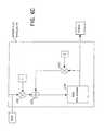
- FIG. 6Cis a lower level diagram illustrating an embodiment ofthe AFRAM or MAFRAM according to the invention, e.g., AFRAM 61 , 63 or MAFRAM 65 of FIG. 6, which is a basic IIR filter.
- Informationis input into a multiplier 631 where it is multiplied with the a coefficient.
- RAM 635is a random access memory that stores 256 elements of information. The stored information from RAM 635 is multiplied with the ⁇ coefficient at a multiplier 637 . The data multiplied with the gain coefficients ⁇ and ⁇ are summed at summer 633 and then forwarded to RAM 635 for storage and output.
- AFRAM 61 , AFRAM 63 , MAFRAM 65together with the time-multiplexed correlation engine (e.g., CF core 31 ), provide the ability to search for pilot symbols over a 64-chip window.
- the pilot symbol searchis a DSP programmable process for searching the three strongest peaks in the received multipath power profile stored in the MAFRAM.
- the AFRAM-filtered I and Q valuesare squared and summed for multipath search processing 67 for selecting the strongest three peaks (in terms of the received power), as described herein and in FIGS. 7 and 7A.
- Pilot post processor 34 of DSP 4determines which multipaths are useful for maximum ratio combining to achieve diversity, which is described in further detail below.
- DSP 4then forwards the best multipaths to the symbol processors 411 through 418 (FIG. 4) in data post processing circuit 35 (FIG. 3) for pilot symbol aided QPSK demodulation and recovery of the data symbols.
- FIG. 7is a diagram illustrating the search processing of the multipath power profile according to the invention.
- Three peaks 1, 2 and 3are selected from the 64-chip search window for demodulation.
- the three strongest peaks(in terms of the received power) are selected by processing a succession of passes through the MAFRAM data.
- the selection processallows DSP 4 to identify the multipath responses for use in demodulation and recovery of the data symbols.
- the strongest peak in the multipath response of the demodulated waveform for the data received from the transmitteris selected and a window (in terms of time or a time period) is assigned thereto.
- the multipath responseis examined again, barring the window for the strongest peak (peak 1), and the second strongest peak is selected and a window is assigned thereto.
- the multipath responseis examined once more, barring the windows for the strongest peak (peak 1) and the second strongest peak (peak 2), and the third strongest peak (peak 3) is selected and a window is assigned thereto.
- the three peaks 1, 2 and 3are supplied to digital signal processing DSP 4 .
- FIG. 7Ais a flow diagram illustrating an embodiment the multipath search processing of the multipath response peaks according to the invention.
- the summed squares of AFRAM-filtered I and Qare stored in MAFRAM 65 (FIG. 6 ).
- the information stored in MAFRAM 65is used for the multipath search processing in a 64-chip window as shown in FIG. 7 .
- the strongest peak in terms of the received power of the multipath responseis stored as index 1 and its magnitude stored as max_power 1.
- a blank-out region 1is set. The blank-out region is ignored for the next examination of the multipath response.
- the blank-out regionis defined by a lower limit 1 and an upper limit 1, as follows:
- step 73the strongest peak in the multipath response is selected by examining the multipath response, while ignoring the blank-out region 1. In effect, the second strongest peak in the entire multipath response is selected, which is stored as index 2 and its magnitude stored as max_power 2.
- step 74another blank-out region 2 is set with a lower limit 2 and an upper limit 2, as follows:
- step 75the strongest peak in terms of the received power in the multipath response is selected by examining the multipath response while ignoring the blank-out regions 1 and 2. In effect, the third strongest peak in the entire multipath response is selected, which is stored as index 3 and its magnitude is stored as max_power 3.
- step 76an additional blank-out region 3 is set with a lower limit 3 and an upper limit 3, as follows:
- the noise power of the multipath responseis stored.
- the noise poweris the sum of all the remaining power in the multipath response.
- the nosie poweris obtained by summing all power elements of the multipath response in the window, while ignoring blank-out regions 1, 2 and 3. The noise power is then reported to DSP 4 .
- pilot post processor 34 of DSP 4determines which multipaths are useful for maximum ratio combining to achieve diversity, which is described in further detail below. DSP 4 then forwards the best multipaths to the symbol processors 411 through 418 (FIG. 4) in data post processor 35 (FIG. 3) for pilot symbol aided QPSK demodulation and recovery of the data symbols.
- FIG. 8is a diagram illustrating the data post processing in the channels of the wireless system according to the invention and, more particularly, the data post processing in the access channel and the traffic channel.
- data symbolsare then processed at the tier 1 data rate. No data symbols are transmitted in the maintenance channel.
- the mode controller 41 of DSP 4indicates the data mode in the access channel
- data symbolsare processed at the tier 1 rate.
- the four PN referenced correlation valuesnamely IrxIref, QrxIref, QrxQref and IrxQref are respectively input into window processor 43 (FIG. 8 and FIG. 4) comprising multipliers 811 , 812 , 813 and 814 .
- Window processor 43performs a complex de-rotation or multiplication of the received correlation values IrxIref, QrxIref, QrxQref and IrxQref with pilot symbol estimates from AFRAM 61 , 63 , and pilot post processor 33 .
- IrxIref and QrxQrefare multiplied with the AFRAM-filtered in-phase component I (e.g., output Pcos 81 from AFRAM 61 ) and QrxIref and IrxQref are multiplied with the AFRAM-filtered quadrature phase component Q (e.g., output Psin 83 from AFRAM 63 ).
- the resultsare input at window select units 801 , 802 , 803 and 804 , respectively, for the multipath selection based on the pilot search processing in a 64-chip window as described herein and in FIGS. 7 and 7A.
- This pilot symbol aided demodulation processproduces QPSK outputs which are rotated to a QPSK signal constellation.
- the 64 chips of correlation values associated with each tier 1 data symbolare not in the proper order and require time demultiplexing to yield appropriately ordered data symbols.
- the four real correlationsare combined into I and Q at summers 821 and 823 and demultiplexed at DEMUX 45 .
- DEMUX 45After demultiplexing, DEMUX 45 outputs the 64 chips of correlation lag for each tier 1 data symbol to the corresponding symbol processors in circuits 831 and 833 .
- symbol processorsThere are eight symbol processors ( 411 through 418 in circuits 831 , 833 ), one for each tier 1 data symbol produced by CF core 31 during the eight phases of the 8-chip correlation process, described herein and in FIGS. 4 and 5.
- the symbol processors ( 411 through 418 ) of one unit 833take the DSP programmable number of correlation lags associated with up to three multipaths and sum the correlation lags to form three outputs.
- the low index (lower limits 1, 2 and/or 3) and high index (upper limits 1, 2 and/or 3) for all three multipathsdetermine which correlation lags are used in forming the three outputs.
- DSP 4performs further integration of the tier 1 data symbols to provide tier 2 and tier 3 data symbols. This is accomplished by summing four tier 1 data symbols to yield one tier 2 data symbol, and summing sixteen tier 1 data symbols to yield one tier 3 data symbol. DSP 4 then uses the three outputs for combining into a single output for signal diversity.
- DSP 4further provides post processing of the data symbols (in data post processor 36 ) for normalizing the outputs of the symbol processors by taking the square root of the absolute value to yield voltage signals.
- This normalizationis needed because complex de-rotation or multiplication has been performed based on the received power of the pilot symbols in units of signal power.
- MRCmaximum ratio combining
- normalizationis required for yielding voltage signals.
- the absolute values(representing the magnitudes of the received power) are taken at circuits 841 and 843 . Then the square root of the signals from absolute value circuits 841 , 843 are generated in square root circuits steps 851 and 853 .
- output of the square root circuits 851 , 853is scaled at divider 861 and divider 863 , respectively.
- the three outputsare then combined in summing circuits 871 and 873 to obtain one output for each of the I and Q components.
- Another type of diversityis spatial diversity, where multiple antenna are provided in the transmitter or receiver for transmitting the same data signals which provide the diversity needed for combining or selecting the data signals. Spatial diversity is achieved by providing the same correlation filter design according to the invention in each antenna receiver in the wireless system.
- FIG. 9is a flow diagram that illustrates an embodiment of the method according to the invention.
- This methodis carried out in a wireless CDMA system using a single, common correlation filter (CF).
- the systemhas a plurality of channels with different data rates and they include the access channel, the maintenance channel, and the traffic channel in which information (e.g., pilot or data symbols or both) is transmitted at the tier 1, tier 2 and tier 3 rates, as described herein in conjunction with FIG. 2 .
- the data rate for transmitting the informationis programmable by digital signal processing (DSP).
- DSPdigital signal processing
- a user-unique codesuch as a PN code, is applied to the information being transmitted in the channels of the wireless system (step 93 ).
- the informationis QPSK modulated and transmitted in any one of the channels.
- the transmitted informationis correlated at the smallest data rate (i.e., the tier 1 rate) using time multiplexing in the correlation filter (CF) of the wireless system (step 95 ).
- the correlated informationis then demultiplexed (step 96 ) and QPSK-demodulated (step 97 ).
- the demodulated informationis summed (step 98 ) at the proper integer multiple of the tier 1 rate to achieve the tier 2 and tier 3 rates, as described herein in conjunction with FIG. 4 .
- step 99three outputs from the demodulated information can be provided and combined for temporal diversity, as described herein in conjunction with FIG. 8 . All the process steps according to the invention described herein are advantageously accomplished using a single, common correlation filter (CF) which eliminates the need for additional correlators or correlation filters for processing received information having multiple data rates.
- CFcommon correlation filter
Landscapes
- Engineering & Computer Science (AREA)
- Computer Networks & Wireless Communication (AREA)
- Signal Processing (AREA)
- Mobile Radio Communication Systems (AREA)
- Noise Elimination (AREA)
- Networks Using Active Elements (AREA)
- Input Circuits Of Receivers And Coupling Of Receivers And Audio Equipment (AREA)
Abstract
Description
Claims (34)
Priority Applications (21)
| Application Number | Priority Date | Filing Date | Title |
|---|---|---|---|
| US09/738,934US6801564B2 (en) | 2000-02-23 | 2000-12-15 | Reverse link correlation filter in wireless communication systems |
| DK01911096TDK1269646T3 (en) | 2000-02-23 | 2001-02-23 | Recurring connection correlation filter in wireless multi-speed CDMA communication systems |
| JP2001562854AJP2004500768A (en) | 2000-02-23 | 2001-02-23 | Reverse link correlation filter in wireless communication |
| AU2001238632AAU2001238632A1 (en) | 2000-02-23 | 2001-02-23 | Reverse link correlation filter in multi rate cdma wireless communication systems |
| DE60138496TDE60138496D1 (en) | 2000-02-23 | 2001-02-23 | Correlation filter for the return channel in a wireless CDMA system with several bit rates |
| KR1020097011801AKR20090073258A (en) | 2000-02-23 | 2001-02-23 | Reverse Link Correlation Filter for Multi-Speed CDMA Wireless Communication Systems |
| AT01911096TATE323344T1 (en) | 2000-02-23 | 2001-02-23 | CORRELATION FILTER FOR THE RETURN CHANNEL IN A WIRELESS CDMA SYSTEM WITH MULTIPLE BIT RATES |
| DE60118715TDE60118715T2 (en) | 2000-02-23 | 2001-02-23 | CORRELATION FILTER FOR THE REVERSE CHANNEL IN A WIRELESS CDMA SYSTEM WITH MULTIPLE BIT RATES |
| KR1020087010717AKR100972804B1 (en) | 2000-02-23 | 2001-02-23 | Reverse Link Correlation Filter for Multi-Speed CDMA Wireless Communication Systems |
| KR1020027011098AKR100845479B1 (en) | 2000-02-23 | 2001-02-23 | Reverse Link Correlation Filter for Multi-Speed CDMA Wireless Communication Systems |
| HK03104706.4AHK1052802B (en) | 2000-02-23 | 2001-02-23 | Reverse link correlation filter in multi rate cdma wireless communication systems |
| AT06075919TATE429738T1 (en) | 2000-02-23 | 2001-02-23 | CORRELATION FILTER FOR THE RETURN CHANNEL IN A WIRELESS CDMA SYSTEM WITH MULTIPLE BIT RATES |
| CA2400934ACA2400934C (en) | 2000-02-23 | 2001-02-23 | Reverse link correlation filter in wireless communication systems |
| KR1020087030512AKR100983849B1 (en) | 2000-02-23 | 2001-02-23 | Reverse Link Correlation Filter for Multi-Speed CDMA Wireless Communication Systems |
| CNB018071325ACN1227828C (en) | 2000-02-23 | 2001-02-23 | CDMA communication system and communication method used in the system |
| EP09158168AEP2088683A1 (en) | 2000-02-23 | 2001-02-23 | Reverse link correlation filter in multi rate CDMA wireless communication systems |
| PCT/US2001/005682WO2001063778A2 (en) | 2000-02-23 | 2001-02-23 | Reverse link correlation filter in multi rate cdma wireless communication systems |
| EP06075919AEP1686697B8 (en) | 2000-02-23 | 2001-02-23 | Reverse link correlation filter in multi rate CDMA wireless communication systems |
| EP01911096AEP1269646B1 (en) | 2000-02-23 | 2001-02-23 | Reverse link correlation filter in multi rate cdma wireless communication systems |
| US10/957,928US7272169B2 (en) | 2000-02-23 | 2004-10-04 | Reverse link correlation filter in wireless communication systems |
| US11/901,571US7613227B2 (en) | 2000-02-23 | 2007-09-17 | Reverse link correlation filter in wireless communication systems |
Applications Claiming Priority (2)
| Application Number | Priority Date | Filing Date | Title |
|---|---|---|---|
| US18436400P | 2000-02-23 | 2000-02-23 | |
| US09/738,934US6801564B2 (en) | 2000-02-23 | 2000-12-15 | Reverse link correlation filter in wireless communication systems |
Related Child Applications (1)
| Application Number | Title | Priority Date | Filing Date |
|---|---|---|---|
| US10/957,928ContinuationUS7272169B2 (en) | 2000-02-23 | 2004-10-04 | Reverse link correlation filter in wireless communication systems |
Publications (2)
| Publication Number | Publication Date |
|---|---|
| US20010030990A1 US20010030990A1 (en) | 2001-10-18 |
| US6801564B2true US6801564B2 (en) | 2004-10-05 |
Family
ID=26880069
Family Applications (3)
| Application Number | Title | Priority Date | Filing Date |
|---|---|---|---|
| US09/738,934Expired - LifetimeUS6801564B2 (en) | 2000-02-23 | 2000-12-15 | Reverse link correlation filter in wireless communication systems |
| US10/957,928Expired - Fee RelatedUS7272169B2 (en) | 2000-02-23 | 2004-10-04 | Reverse link correlation filter in wireless communication systems |
| US11/901,571Expired - Fee RelatedUS7613227B2 (en) | 2000-02-23 | 2007-09-17 | Reverse link correlation filter in wireless communication systems |
Family Applications After (2)
| Application Number | Title | Priority Date | Filing Date |
|---|---|---|---|
| US10/957,928Expired - Fee RelatedUS7272169B2 (en) | 2000-02-23 | 2004-10-04 | Reverse link correlation filter in wireless communication systems |
| US11/901,571Expired - Fee RelatedUS7613227B2 (en) | 2000-02-23 | 2007-09-17 | Reverse link correlation filter in wireless communication systems |
Country Status (12)
| Country | Link |
|---|---|
| US (3) | US6801564B2 (en) |
| EP (3) | EP1686697B8 (en) |
| JP (1) | JP2004500768A (en) |
| KR (4) | KR100983849B1 (en) |
| CN (1) | CN1227828C (en) |
| AT (2) | ATE429738T1 (en) |
| AU (1) | AU2001238632A1 (en) |
| CA (1) | CA2400934C (en) |
| DE (2) | DE60118715T2 (en) |
| DK (1) | DK1269646T3 (en) |
| HK (1) | HK1052802B (en) |
| WO (1) | WO2001063778A2 (en) |
Cited By (16)
| Publication number | Priority date | Publication date | Assignee | Title |
|---|---|---|---|---|
| US20010026599A1 (en)* | 2000-02-08 | 2001-10-04 | Tantivy Communications, Inc. | Access channel structure for wireless communication system |
| US20020027892A1 (en)* | 2000-09-05 | 2002-03-07 | Masayuki Sasaki | CDMA base transceiver system |
| US20030095531A1 (en)* | 2001-11-20 | 2003-05-22 | Analog Devices, Inc. | Methods and apparatus for spread spectrum signal processing using a reconfigurable coprocessor |
| US20040240589A1 (en)* | 2003-05-21 | 2004-12-02 | Infineon Technologies Ag | Hardware apparatus for conditioning pilot symbols for channel estimation using adaptive low-pass filtering |
| WO2004102816A3 (en)* | 2003-05-12 | 2006-03-02 | Qualcomm Inc | Fast frequency hopping with a code division multiplexed pilot in an ofdma system |
| US20060133312A1 (en)* | 2004-12-22 | 2006-06-22 | Qualcomm Incorporated | Method of implicit deassignment of resources |
| US20070054633A1 (en)* | 2005-09-08 | 2007-03-08 | Nokia Corporation | Data transmission scheme in wireless communication system |
| WO2007037630A1 (en)* | 2005-09-28 | 2007-04-05 | Samsung Electronics Co., Ltd. | Method for maximal ratio combining of spatially filtered signals and apparatus therefor |
| US20080214218A1 (en)* | 2005-09-28 | 2008-09-04 | Samsung Electronics Co., Ltd. | Method for Maximal Ratio Combining of Spatially Filtered Signals and Apparatus Therefor |
| US20080317143A1 (en)* | 2005-12-08 | 2008-12-25 | Sun-Heui Ryoo | Apparatus and Method for Correcting Iterative Residual Frequency and Phase in Turbo Coded Ofdm System |
| US20110098970A1 (en)* | 2009-10-22 | 2011-04-28 | Sick Ag | Measurement of distances or of distance changes |
| US8238923B2 (en) | 2004-12-22 | 2012-08-07 | Qualcomm Incorporated | Method of using shared resources in a communication system |
| US8611283B2 (en) | 2004-01-28 | 2013-12-17 | Qualcomm Incorporated | Method and apparatus of using a single channel to provide acknowledgement and assignment messages |
| US8638870B2 (en) | 2004-12-22 | 2014-01-28 | Qualcomm Incorporated | MC-CDMA multiplexing in an orthogonal uplink |
| US8724555B2 (en) | 2002-10-29 | 2014-05-13 | Qualcomm Incorporated | Uplink pilot and signaling transmission in wireless communication systems |
| US9480074B2 (en) | 2004-07-23 | 2016-10-25 | Qualcomm Incorporated | Enabling quick and easy demodulation |
Families Citing this family (39)
| Publication number | Priority date | Publication date | Assignee | Title |
|---|---|---|---|---|
| US7079523B2 (en)* | 2000-02-07 | 2006-07-18 | Ipr Licensing, Inc. | Maintenance link using active/standby request channels |
| US6222832B1 (en) | 1998-06-01 | 2001-04-24 | Tantivy Communications, Inc. | Fast Acquisition of traffic channels for a highly variable data rate reverse link of a CDMA wireless communication system |
| US7936728B2 (en) | 1997-12-17 | 2011-05-03 | Tantivy Communications, Inc. | System and method for maintaining timing of synchronization messages over a reverse link of a CDMA wireless communication system |
| US9525923B2 (en) | 1997-12-17 | 2016-12-20 | Intel Corporation | Multi-detection of heartbeat to reduce error probability |
| US7394791B2 (en) | 1997-12-17 | 2008-07-01 | Interdigital Technology Corporation | Multi-detection of heartbeat to reduce error probability |
| US8134980B2 (en) | 1998-06-01 | 2012-03-13 | Ipr Licensing, Inc. | Transmittal of heartbeat signal at a lower level than heartbeat request |
| US7773566B2 (en) | 1998-06-01 | 2010-08-10 | Tantivy Communications, Inc. | System and method for maintaining timing of synchronization messages over a reverse link of a CDMA wireless communication system |
| AU3673001A (en) | 2000-02-07 | 2001-08-14 | Tantivy Communications, Inc. | Minimal maintenance link to support synchronization |
| US7911993B2 (en)* | 2000-07-19 | 2011-03-22 | Ipr Licensing, Inc. | Method and apparatus for allowing soft handoff of a CDMA reverse link utilizing an orthogonal channel structure |
| US8537656B2 (en) | 2000-07-19 | 2013-09-17 | Ipr Licensing, Inc. | Method for compensating for multi-path of a CDMA reverse link utilizing an orthogonal channel structure |
| US8155096B1 (en) | 2000-12-01 | 2012-04-10 | Ipr Licensing Inc. | Antenna control system and method |
| US6954448B2 (en) | 2001-02-01 | 2005-10-11 | Ipr Licensing, Inc. | Alternate channel for carrying selected message types |
| US7551663B1 (en) | 2001-02-01 | 2009-06-23 | Ipr Licensing, Inc. | Use of correlation combination to achieve channel detection |
| US7218623B1 (en) | 2001-05-04 | 2007-05-15 | Ipr Licensing, Inc. | Coded reverse link messages for closed-loop power control of forward link control messages |
| EP2479905B1 (en) | 2001-06-13 | 2017-03-15 | Intel Corporation | Method and apparatuses for transmittal of heartbeat signal at a lower level than heartbeat request |
| US6917581B2 (en) | 2001-07-17 | 2005-07-12 | Ipr Licensing, Inc. | Use of orthogonal or near orthogonal codes in reverse link |
| DE60134027D1 (en)* | 2001-10-23 | 2008-06-26 | Texas Instruments Inc | Wireless communication system with processor-controlled rake finger tasks |
| US7027492B2 (en)* | 2002-05-01 | 2006-04-11 | Texas Instruments Incorporated | Wireless communication system with processor requested RAKE finger tasks |
| US7139274B2 (en) | 2002-08-23 | 2006-11-21 | Qualcomm, Incorporated | Method and system for a data transmission in a communication system |
| US7206831B1 (en)* | 2002-08-26 | 2007-04-17 | Finisar Corporation | On card programmable filtering and searching for captured network data |
| US7180963B2 (en)* | 2002-11-25 | 2007-02-20 | Ali Corporation | Digital receiver capable of processing modulated signals at various data rates |
| US8179833B2 (en) | 2002-12-06 | 2012-05-15 | Qualcomm Incorporated | Hybrid TDM/OFDM/CDM reverse link transmission |
| GB0410617D0 (en)* | 2004-05-12 | 2004-06-16 | Ttp Communications Ltd | Path searching |
| US20060269024A1 (en)* | 2005-05-27 | 2006-11-30 | Francis Dominique | Initial multi-path acquisition of random access channels |
| US7764656B2 (en)* | 2005-07-13 | 2010-07-27 | Alcatel-Lucent Usa Inc. | Methods of multipath acquisition for dedicated traffic channels |
| US7929499B2 (en)* | 2005-07-13 | 2011-04-19 | Alcatel-Lucent Usa Inc. | Methods of multipath acquisition for dedicated traffic channels |
| US7856071B2 (en)* | 2005-07-26 | 2010-12-21 | Alcatel-Lucent Usa Inc. | Multi-path acquisition in the presence of very high data rate users |
| JP2007166350A (en)* | 2005-12-15 | 2007-06-28 | Agilent Technol Inc | Gate array program device, measuring device, program |
| US20070213941A1 (en)* | 2006-03-13 | 2007-09-13 | Levy Schmuel | Techniques to reduce power consumption in mobile devices |
| CN101202583B (en)* | 2006-12-13 | 2012-07-04 | 中兴通讯股份有限公司 | Method for generating forward data rate in a communicating system |
| EP1983656A1 (en)* | 2007-04-19 | 2008-10-22 | MediaTek Inc. | Shared filter design for pilot symbol averaging in rake fingers in WCDMA systems |
| EP2031760B1 (en)* | 2007-08-31 | 2014-02-26 | Mitsubishi Electric R&D Centre Europe B.V. | Method for estimating, in a communication system, the level of interference plus noise affecting received signals representative of a set of received pilot symbols |
| JP2010011061A (en)* | 2008-06-26 | 2010-01-14 | Nippon Soken Inc | Wireless communication system |
| US20110098880A1 (en)* | 2009-10-23 | 2011-04-28 | Basir Otman A | Reduced transmission of vehicle operating data |
| US9361706B2 (en)* | 2009-11-30 | 2016-06-07 | Brigham Young University | Real-time optical flow sensor design and its application to obstacle detection |
| CN102916736B (en)* | 2012-10-12 | 2016-01-20 | 广州海格通信集团股份有限公司 | The radio monitoring method and apparatus of wireless communication system |
| US9621205B2 (en)* | 2015-03-26 | 2017-04-11 | Vt Idirect, Inc. | Apparatus and method for frequency estimation ambiguity removal of a burst signal |
| US9554506B2 (en)* | 2015-04-27 | 2017-01-31 | Cnh Industrial America Llc | Fluid flow monitoring and control system for an agricultural sprayer |
| DE102018206137A1 (en)* | 2018-04-20 | 2019-10-24 | Fraunhofer-Gesellschaft zur Förderung der angewandten Forschung e.V. | Packet correlator for a radio transmission system |
Citations (14)
| Publication number | Priority date | Publication date | Assignee | Title |
|---|---|---|---|---|
| US4675839A (en) | 1985-04-10 | 1987-06-23 | Allied Corporation | Receiver for a spread spectrum communication system having a time-multiplexed convolver |
| FR2629931A1 (en) | 1988-04-08 | 1989-10-13 | Lmt Radio Professionelle | ASYNCHRONOUS DIGITAL CORRELATOR AND DEMODULATORS COMPRISING SUCH A CORRELATOR |
| US5329547A (en) | 1993-03-11 | 1994-07-12 | Motorola, Inc. | Method and apparatus for coherent communication in a spread-spectrum communication system |
| US5513216A (en) | 1994-10-13 | 1996-04-30 | At&T Corp. | Hybrid equalizer arrangement for use in data communications equipment |
| US5619524A (en) | 1994-10-04 | 1997-04-08 | Motorola, Inc. | Method and apparatus for coherent communication reception in a spread-spectrum communication system |
| US5920551A (en) | 1995-06-23 | 1999-07-06 | Electronics And Telecommunications Research Institute | Channel structure with burst pilot in reverse link |
| US5946344A (en) | 1997-04-07 | 1999-08-31 | Intermec Ip Corp. | Multiple-rate direct sequence architecture utilizing a fixed chipping rate and variable spreading code lengths |
| US5949833A (en) | 1995-11-13 | 1999-09-07 | Lucent Technologies Inc. | Method and apparatus to implement antenna diversity for direct sequence spread spectrum receivers |
| US5991332A (en) | 1995-06-30 | 1999-11-23 | Interdigital Technology Corporation | Adaptive matched filter and vector correlator for a code division multiple access (CDMA) modem |
| US6005887A (en) | 1996-11-14 | 1999-12-21 | Ericcsson, Inc. | Despreading of direct sequence spread spectrum communications signals |
| US6125136A (en)* | 1997-12-31 | 2000-09-26 | Sony Corporation | Method and apparatus for demodulating trellis coded direct sequence spread spectrum communication signals |
| EP1039653A2 (en) | 1999-03-23 | 2000-09-27 | Matsushita Electric Industrial Co., Ltd. | Apparatus and method for receiving and despreading DS-CDMA signals |
| US6215813B1 (en)* | 1997-12-31 | 2001-04-10 | Sony Corporation | Method and apparatus for encoding trellis coded direct sequence spread spectrum communication signals |
| US6233271B1 (en)* | 1997-12-31 | 2001-05-15 | Sony Corporation | Method and apparatus for decoding trellis coded direct sequence spread spectrum communication signals |
Family Cites Families (25)
| Publication number | Priority date | Publication date | Assignee | Title |
|---|---|---|---|---|
| US5237586A (en)* | 1992-03-25 | 1993-08-17 | Ericsson-Ge Mobile Communications Holding, Inc. | Rake receiver with selective ray combining |
| KR950003668B1 (en)* | 1992-04-29 | 1995-04-17 | 삼성전자 주식회사 | Suboptimum receiver of superposed modulated signal |
| US5442625A (en)* | 1994-05-13 | 1995-08-15 | At&T Ipm Corp | Code division multiple access system providing variable data rate access to a user |
| US5659573A (en)* | 1994-10-04 | 1997-08-19 | Motorola, Inc. | Method and apparatus for coherent reception in a spread-spectrum receiver |
| US5671221A (en)* | 1995-06-14 | 1997-09-23 | Sharp Microelectronics Technology, Inc. | Receiving method and apparatus for use in a spread-spectrum communication system |
| US5799011A (en)* | 1996-03-29 | 1998-08-25 | Motorola, Inc. | CDMA power control channel estimation using dynamic coefficient scaling |
| JPH09307477A (en)* | 1996-05-16 | 1997-11-28 | Pfu Ltd | Spread spectrum communication device |
| US6061359A (en)* | 1996-08-02 | 2000-05-09 | Golden Bridge Technology, Inc. | Increased-capacity, packet spread-spectrum system and method |
| JP3462034B2 (en)* | 1997-02-27 | 2003-11-05 | 株式会社日立国際電気 | CDMA receiver |
| WO1998047253A1 (en)* | 1997-04-16 | 1998-10-22 | Ntt Mobile Communications Network Inc. | Cdma communication method |
| JP2924864B2 (en)* | 1997-06-16 | 1999-07-26 | 日本電気株式会社 | Adaptive rake reception method |
| US6222875B1 (en)* | 1997-07-11 | 2001-04-24 | Telefonaktiebolaget Lm Ericsson (Publ) | Low-delay rate detection for variable rate communication systems |
| JP3305639B2 (en)* | 1997-12-24 | 2002-07-24 | 株式会社エヌ・ティ・ティ・ドコモ | RAKE receiver in direct spread CDMA transmission system |
| US6160803A (en)* | 1998-01-12 | 2000-12-12 | Golden Bridge Technology, Inc. | High processing gain spread spectrum TDMA system and method |
| JPH11298401A (en)* | 1998-04-14 | 1999-10-29 | Matsushita Electric Ind Co Ltd | Synchronous processing device and synchronous processing method |
| JP3420700B2 (en)* | 1998-05-07 | 2003-06-30 | 株式会社東芝 | Code synchronization acquisition circuit for spread spectrum signal |
| US6229842B1 (en)* | 1998-07-16 | 2001-05-08 | Telefonaktiebolaget Lm Ericsson (Publ) | Adaptive path selection threshold setting for DS-CDMA receivers |
| US6331998B1 (en)* | 1998-08-28 | 2001-12-18 | Industrial Technology Research Institute | Partially matched filter for spread spectrum communication |
| US6456647B1 (en)* | 1998-12-16 | 2002-09-24 | Lsi Logic Corporation | Two step signal recovery scheme for a receiver |
| JP2000341173A (en)* | 1999-03-23 | 2000-12-08 | Matsushita Electric Ind Co Ltd | Wireless receiving apparatus and wireless receiving method |
| EP1069696B1 (en)* | 1999-06-24 | 2006-09-27 | Alcatel | Receiver and method with enhanced performance for CDMA transmission |
| DE69900302T2 (en)* | 1999-06-24 | 2002-05-08 | Alcatel, Paris | Receiver and method for CDMA transmission with improved path finder |
| US6301291B1 (en) | 2000-02-03 | 2001-10-09 | Tantivy Communications, Inc. | Pilot symbol assisted modulation and demodulation in wireless communication systems |
| US6532251B1 (en)* | 2001-08-16 | 2003-03-11 | Motorola, Inc. | Data message bit synchronization and local time correction methods and architectures |
| US6775319B2 (en)* | 2001-08-16 | 2004-08-10 | Motorola, Inc. | Spread spectrum receiver architectures and methods therefor |
- 2000
- 2000-12-15USUS09/738,934patent/US6801564B2/ennot_activeExpired - Lifetime
- 2001
- 2001-02-23EPEP06075919Apatent/EP1686697B8/ennot_activeExpired - Lifetime
- 2001-02-23KRKR1020087030512Apatent/KR100983849B1/ennot_activeExpired - Fee Related
- 2001-02-23EPEP09158168Apatent/EP2088683A1/ennot_activeWithdrawn
- 2001-02-23CACA2400934Apatent/CA2400934C/ennot_activeExpired - Fee Related
- 2001-02-23EPEP01911096Apatent/EP1269646B1/ennot_activeExpired - Lifetime
- 2001-02-23HKHK03104706.4Apatent/HK1052802B/ennot_activeIP Right Cessation
- 2001-02-23DKDK01911096Tpatent/DK1269646T3/enactive
- 2001-02-23ATAT06075919Tpatent/ATE429738T1/ennot_activeIP Right Cessation
- 2001-02-23KRKR1020097011801Apatent/KR20090073258A/ennot_activeWithdrawn
- 2001-02-23DEDE60118715Tpatent/DE60118715T2/ennot_activeExpired - Lifetime
- 2001-02-23JPJP2001562854Apatent/JP2004500768A/enactivePending
- 2001-02-23DEDE60138496Tpatent/DE60138496D1/ennot_activeExpired - Lifetime
- 2001-02-23WOPCT/US2001/005682patent/WO2001063778A2/enactiveIP Right Grant
- 2001-02-23KRKR1020087010717Apatent/KR100972804B1/ennot_activeExpired - Fee Related
- 2001-02-23CNCNB018071325Apatent/CN1227828C/ennot_activeExpired - Fee Related
- 2001-02-23KRKR1020027011098Apatent/KR100845479B1/ennot_activeExpired - Fee Related
- 2001-02-23AUAU2001238632Apatent/AU2001238632A1/ennot_activeAbandoned
- 2001-02-23ATAT01911096Tpatent/ATE323344T1/ennot_activeIP Right Cessation
- 2004
- 2004-10-04USUS10/957,928patent/US7272169B2/ennot_activeExpired - Fee Related
- 2007
- 2007-09-17USUS11/901,571patent/US7613227B2/ennot_activeExpired - Fee Related
Patent Citations (14)
| Publication number | Priority date | Publication date | Assignee | Title |
|---|---|---|---|---|
| US4675839A (en) | 1985-04-10 | 1987-06-23 | Allied Corporation | Receiver for a spread spectrum communication system having a time-multiplexed convolver |
| FR2629931A1 (en) | 1988-04-08 | 1989-10-13 | Lmt Radio Professionelle | ASYNCHRONOUS DIGITAL CORRELATOR AND DEMODULATORS COMPRISING SUCH A CORRELATOR |
| US5329547A (en) | 1993-03-11 | 1994-07-12 | Motorola, Inc. | Method and apparatus for coherent communication in a spread-spectrum communication system |
| US5619524A (en) | 1994-10-04 | 1997-04-08 | Motorola, Inc. | Method and apparatus for coherent communication reception in a spread-spectrum communication system |
| US5513216A (en) | 1994-10-13 | 1996-04-30 | At&T Corp. | Hybrid equalizer arrangement for use in data communications equipment |
| US5920551A (en) | 1995-06-23 | 1999-07-06 | Electronics And Telecommunications Research Institute | Channel structure with burst pilot in reverse link |
| US5991332A (en) | 1995-06-30 | 1999-11-23 | Interdigital Technology Corporation | Adaptive matched filter and vector correlator for a code division multiple access (CDMA) modem |
| US5949833A (en) | 1995-11-13 | 1999-09-07 | Lucent Technologies Inc. | Method and apparatus to implement antenna diversity for direct sequence spread spectrum receivers |
| US6005887A (en) | 1996-11-14 | 1999-12-21 | Ericcsson, Inc. | Despreading of direct sequence spread spectrum communications signals |
| US5946344A (en) | 1997-04-07 | 1999-08-31 | Intermec Ip Corp. | Multiple-rate direct sequence architecture utilizing a fixed chipping rate and variable spreading code lengths |
| US6125136A (en)* | 1997-12-31 | 2000-09-26 | Sony Corporation | Method and apparatus for demodulating trellis coded direct sequence spread spectrum communication signals |
| US6215813B1 (en)* | 1997-12-31 | 2001-04-10 | Sony Corporation | Method and apparatus for encoding trellis coded direct sequence spread spectrum communication signals |
| US6233271B1 (en)* | 1997-12-31 | 2001-05-15 | Sony Corporation | Method and apparatus for decoding trellis coded direct sequence spread spectrum communication signals |
| EP1039653A2 (en) | 1999-03-23 | 2000-09-27 | Matsushita Electric Industrial Co., Ltd. | Apparatus and method for receiving and despreading DS-CDMA signals |
Non-Patent Citations (3)
| Title |
|---|
| Gansman et al., IEEE Transactions on Communications, 45(10):1327-1337, Oct. 1997. |
| Schramm et al., IEEE Transactions on Communications, 46(12):1560-1563, Dec. 1998. |
| Schramm, IEEE Transactions on Communications, 46(9):1122-1124, Sep. 1998. |
Cited By (35)
| Publication number | Priority date | Publication date | Assignee | Title |
|---|---|---|---|---|
| US9780930B2 (en) | 2000-02-08 | 2017-10-03 | Ipr Licensing, Inc. | Communicating reference and data information in a wireless network |
| US20010026599A1 (en)* | 2000-02-08 | 2001-10-04 | Tantivy Communications, Inc. | Access channel structure for wireless communication system |
| US20090097455A1 (en)* | 2000-02-08 | 2009-04-16 | Ipr Licensing, Inc. | Access channel structure for wireless communication system |
| US7483473B2 (en) | 2000-02-08 | 2009-01-27 | Ipr Licensing, Inc. | Access channel structure for wireless communication system |
| US6904079B2 (en)* | 2000-02-08 | 2005-06-07 | Ipr Licensing, Inc. | Access channel structure for wireless communication system |
| US20050175071A1 (en)* | 2000-02-08 | 2005-08-11 | Ipr Licensing, Inc. | Access channel structure for wireless communication system |
| US8958457B2 (en) | 2000-02-08 | 2015-02-17 | Ipr Licensing, Inc. | Channel structure for a wireless communication system |
| US7012908B2 (en)* | 2000-09-05 | 2006-03-14 | Hitachi Kokusai Electric Inc. | CDMA base transceiver system |
| US20020027892A1 (en)* | 2000-09-05 | 2002-03-07 | Masayuki Sasaki | CDMA base transceiver system |
| US7433389B2 (en)* | 2001-11-20 | 2008-10-07 | Mediatek Inc. | Methods and apparatus for spread spectrum signal processing using a reconfigurable coprocessor |
| US20030095531A1 (en)* | 2001-11-20 | 2003-05-22 | Analog Devices, Inc. | Methods and apparatus for spread spectrum signal processing using a reconfigurable coprocessor |
| US9155106B2 (en) | 2002-10-29 | 2015-10-06 | Qualcomm Incorporated | Uplink pilot and signaling transmission in wireless communication systems |
| US8724555B2 (en) | 2002-10-29 | 2014-05-13 | Qualcomm Incorporated | Uplink pilot and signaling transmission in wireless communication systems |
| WO2004102816A3 (en)* | 2003-05-12 | 2006-03-02 | Qualcomm Inc | Fast frequency hopping with a code division multiplexed pilot in an ofdma system |
| US8102832B2 (en) | 2003-05-12 | 2012-01-24 | Qualcomm Incorporated | Fast frequency hopping with a code division multiplexed pilot in an OFDMA system |
| US7636374B2 (en)* | 2003-05-21 | 2009-12-22 | Infineon Technologies Ag | Hardware apparatus for conditioning pilot symbols for channel estimation using adaptive low-pass filtering |
| US20040240589A1 (en)* | 2003-05-21 | 2004-12-02 | Infineon Technologies Ag | Hardware apparatus for conditioning pilot symbols for channel estimation using adaptive low-pass filtering |
| US8611283B2 (en) | 2004-01-28 | 2013-12-17 | Qualcomm Incorporated | Method and apparatus of using a single channel to provide acknowledgement and assignment messages |
| US9480074B2 (en) | 2004-07-23 | 2016-10-25 | Qualcomm Incorporated | Enabling quick and easy demodulation |
| US9871617B2 (en) | 2004-07-23 | 2018-01-16 | Qualcomm Incorporated | Method of optimizing portions of a frame |
| US8649451B2 (en) | 2004-12-22 | 2014-02-11 | Qualcomm Incorporated | MC-CDMA multiplexing in an orthogonal uplink |
| US8831115B2 (en) | 2004-12-22 | 2014-09-09 | Qualcomm Incorporated | MC-CDMA multiplexing in an orthogonal uplink |
| US8238923B2 (en) | 2004-12-22 | 2012-08-07 | Qualcomm Incorporated | Method of using shared resources in a communication system |
| US20060133312A1 (en)* | 2004-12-22 | 2006-06-22 | Qualcomm Incorporated | Method of implicit deassignment of resources |
| US7453849B2 (en) | 2004-12-22 | 2008-11-18 | Qualcomm Incorporated | Method of implicit deassignment of resources |
| US8638870B2 (en) | 2004-12-22 | 2014-01-28 | Qualcomm Incorporated | MC-CDMA multiplexing in an orthogonal uplink |
| US8817897B2 (en) | 2004-12-22 | 2014-08-26 | Qualcomm Incorporated | MC-CDMA multiplexing in an orthogonal uplink |
| US7542734B2 (en)* | 2005-09-08 | 2009-06-02 | Nokia Corporation | Data transmission scheme in wireless communication system |
| US20070054633A1 (en)* | 2005-09-08 | 2007-03-08 | Nokia Corporation | Data transmission scheme in wireless communication system |
| US20080214218A1 (en)* | 2005-09-28 | 2008-09-04 | Samsung Electronics Co., Ltd. | Method for Maximal Ratio Combining of Spatially Filtered Signals and Apparatus Therefor |
| WO2007037630A1 (en)* | 2005-09-28 | 2007-04-05 | Samsung Electronics Co., Ltd. | Method for maximal ratio combining of spatially filtered signals and apparatus therefor |
| US7925234B2 (en) | 2005-09-28 | 2011-04-12 | Samsung Electronics Co., Ltd. | Method for maximal ratio combining of spatially filtered signals and apparatus therefor |
| US20080317143A1 (en)* | 2005-12-08 | 2008-12-25 | Sun-Heui Ryoo | Apparatus and Method for Correcting Iterative Residual Frequency and Phase in Turbo Coded Ofdm System |
| US20110098970A1 (en)* | 2009-10-22 | 2011-04-28 | Sick Ag | Measurement of distances or of distance changes |
| US8488110B2 (en)* | 2009-10-22 | 2013-07-16 | Sick Ag | Measurement of distances or of distance changes |
Also Published As
Similar Documents
| Publication | Publication Date | Title |
|---|---|---|
| US6801564B2 (en) | Reverse link correlation filter in wireless communication systems | |
| US5870378A (en) | Method and apparatus of a multi-code code division multiple access receiver having a shared accumulator circuits | |
| US5881056A (en) | Method and apparatus of a multi-code code division multiple access receiver having shared accumulator circuits | |
| US6449266B1 (en) | Data transmission method, transmitter, and receiver | |
| US20030235238A1 (en) | Multipath channel tap delay estimation in a CDMA spread spectrum receiver | |
| US20030189972A1 (en) | Method and device for interference cancellation in a CDMA wireless communication system | |
| CN1310889A (en) | Combining sub-chip resolution samples in fingers of a spread-spectrum rake receiver | |
| JP2001057545A (en) | Method and device for estimating spread spectrum channel | |
| EP1774670B1 (en) | Use of adaptive filters in cdma wireless systems employing pilot signals | |
| JP4059443B2 (en) | Method and WCDMA for receiving a multi-rate physical channel | |
| EP1350338B1 (en) | Time tracking in a non-negligible multipath spacing environment | |
| HK1096781A (en) | Reverse link correlation filter in multi rate cdma wireless communication systems | |
| HK1135244A (en) | Reverse link correlation filter in multi rate cdma wireless communication systems | |
| EP1235358B1 (en) | System and method for extracting soft symbols in direct sequence spread spectrum communications | |
| JP2001156683A (en) | Spread spectrum demodulator |
Legal Events
| Date | Code | Title | Description |
|---|---|---|---|
| AS | Assignment | Owner name:TANTIVY COMMUNICATIONS INC., FLORIDA Free format text:ASSIGNMENT OF ASSIGNORS INTEREST;ASSIGNORS:ROUPHAEL, ANTOINE J.;HOFFMANN, JOHN E.;NELSON, GEORGE RODNEY JR.;AND OTHERS;REEL/FRAME:011359/0954;SIGNING DATES FROM 20000823 TO 20001212 | |
| AS | Assignment | Owner name:SILICON VALLEY BANK, CALIFORNIA Free format text:SECURITY AGREEMENT;ASSIGNOR:TANTIVY COMMUNICATIONS, INC.;REEL/FRAME:012506/0808 Effective date:20011130 | |
| AS | Assignment | Owner name:IPR HOLDINGS DELAWARE, INC., PENNSYLVANIA Free format text:SECURITY INTEREST;ASSIGNOR:TANTIVY COMMUNICATIONS, INC.;REEL/FRAME:014289/0207 Effective date:20030722 | |
| AS | Assignment | Owner name:INTERDIGITAL PATENT CORPORATION, DELAWARE Free format text:ASSIGNMENT OF ASSIGNORS INTEREST;ASSIGNOR:INTERDIGITAL ACQUISITION CORPORATION;REEL/FRAME:014351/0777 Effective date:20040218 | |
| AS | Assignment | Owner name:INTERDIGITAL ACQUISITION CORP., DELAWARE Free format text:ASSIGNMENT OF ASSIGNORS INTEREST;ASSIGNOR:TANTIVY COMMUNICATIONS, INC.;REEL/FRAME:015000/0141 Effective date:20030730 Owner name:INTERDIGITAL PATENT CORPORATION, DELAWARE Free format text:MERGER;ASSIGNOR:INTERDIGITAL ACQUISITION CORP.;REEL/FRAME:015000/0577 Effective date:20040218 | |
| AS | Assignment | Owner name:IPR LICENSING, INC., DELAWARE Free format text:ASSIGNMENT OF ASSIGNORS INTEREST;ASSIGNOR:INTERDIGITAL PATENT CORPORATION;REEL/FRAME:014420/0435 Effective date:20040309 | |
| STCF | Information on status: patent grant | Free format text:PATENTED CASE | |
| FPAY | Fee payment | Year of fee payment:4 | |
| FPAY | Fee payment | Year of fee payment:8 | |
| AS | Assignment | Owner name:TANTIVY COMMUNICATIONS, INC., FLORIDA Free format text:RELEASE BY SECURED PARTY;ASSIGNOR:SILICON VALLEY BANK;REEL/FRAME:028345/0179 Effective date:20061206 Owner name:IPR HOLDINGS DELAWARE, INC., DELAWARE Free format text:LICENSE;ASSIGNOR:TANTIVY COMMUNICATIONS, INC.;REEL/FRAME:028349/0387 Effective date:20020822 Owner name:TANTIVY COMMUNICATIONS, INC., FLORIDA Free format text:RELEASE BY SECURED PARTY;ASSIGNOR:SILICON VALLEY BANK;REEL/FRAME:028339/0500 Effective date:20030423 | |
| FPAY | Fee payment | Year of fee payment:12 |