US6801428B2 - Rack mountable computer component fan cooling arrangement and method - Google Patents
Rack mountable computer component fan cooling arrangement and methodDownload PDFInfo
- Publication number
- US6801428B2 US6801428B2US10/449,608US44960803AUS6801428B2US 6801428 B2US6801428 B2US 6801428B2US 44960803 AUS44960803 AUS 44960803AUS 6801428 B2US6801428 B2US 6801428B2
- Authority
- US
- United States
- Prior art keywords
- tray
- moving devices
- air moving
- computer components
- rack
- Prior art date
- Legal status (The legal status is an assumption and is not a legal conclusion. Google has not performed a legal analysis and makes no representation as to the accuracy of the status listed.)
- Expired - Lifetime
Links
Images


Classifications
- H—ELECTRICITY
- H05—ELECTRIC TECHNIQUES NOT OTHERWISE PROVIDED FOR
- H05K—PRINTED CIRCUITS; CASINGS OR CONSTRUCTIONAL DETAILS OF ELECTRIC APPARATUS; MANUFACTURE OF ASSEMBLAGES OF ELECTRICAL COMPONENTS
- H05K7/00—Constructional details common to different types of electric apparatus
- H05K7/20—Modifications to facilitate cooling, ventilating, or heating
- H05K7/20709—Modifications to facilitate cooling, ventilating, or heating for server racks or cabinets; for data centers, e.g. 19-inch computer racks
- H05K7/20718—Forced ventilation of a gaseous coolant
- H05K7/20736—Forced ventilation of a gaseous coolant within cabinets for removing heat from server blades
- G—PHYSICS
- G06—COMPUTING OR CALCULATING; COUNTING
- G06F—ELECTRIC DIGITAL DATA PROCESSING
- G06F1/00—Details not covered by groups G06F3/00 - G06F13/00 and G06F21/00
- G06F1/16—Constructional details or arrangements
- G06F1/18—Packaging or power distribution
- G06F1/181—Enclosures
- G—PHYSICS
- G06—COMPUTING OR CALCULATING; COUNTING
- G06F—ELECTRIC DIGITAL DATA PROCESSING
- G06F1/00—Details not covered by groups G06F3/00 - G06F13/00 and G06F21/00
- G06F1/16—Constructional details or arrangements
- G06F1/18—Packaging or power distribution
- G06F1/183—Internal mounting support structures, e.g. for printed circuit boards, internal connecting means
- G—PHYSICS
- G06—COMPUTING OR CALCULATING; COUNTING
- G06F—ELECTRIC DIGITAL DATA PROCESSING
- G06F1/00—Details not covered by groups G06F3/00 - G06F13/00 and G06F21/00
- G06F1/16—Constructional details or arrangements
- G06F1/20—Cooling means
- H—ELECTRICITY
- H05—ELECTRIC TECHNIQUES NOT OTHERWISE PROVIDED FOR
- H05K—PRINTED CIRCUITS; CASINGS OR CONSTRUCTIONAL DETAILS OF ELECTRIC APPARATUS; MANUFACTURE OF ASSEMBLAGES OF ELECTRICAL COMPONENTS
- H05K7/00—Constructional details common to different types of electric apparatus
- H05K7/14—Mounting supporting structure in casing or on frame or rack
- H05K7/1485—Servers; Data center rooms, e.g. 19-inch computer racks
- H05K7/1488—Cabinets therefor, e.g. chassis or racks or mechanical interfaces between blades and support structures
Definitions
- the present inventionrelates in general to a new and improved method computer components adapted for rack mounting. It more particularly relates to such a method and apparatus for cooling computer components adapted to be mounted in a compact configuration.
- the housing for each computer devicemust have a certain height dimensions according to the Standard.
- the height dimensionmust be a multiple of a standard unit “U”.
- there can also be standard rack mountable computer componentswhich are 1 U, 2 U, 3 U, 4 U and so on.
- racksare provided for storage of computer components in tightly spaced, densely packed horizontal dispositions, and each computer component mounted in the rack is suitably dimensioned in multiples of standard unit U.
- the racksare movably mounted on casters or the like so that they can be readily positioned in, for example, a computer room having a tightly controlled air conditioning system to ensure proper cooling of the computer equipment.
- each componentin order to assemble the rack mounted system for installation at the site, each component must be installed in place within the rack, and then the cabling for each unit is routed within the rack at its back plane space. Such an operation is time consuming, and therefore expensive since highly trained personnel are required to do such an installation. Furthermore, once installed, in order to replace a malfunctioning computer component, the entire system, or at least a substantial portion thereof, must be shut down so that the malfunctioning unit can be disassembled, and a replacement unit installed and reconnected electrically. This, too, is time consuming and expensive.
- intake and exhaust fansare employed.
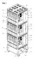
- FIG. 1is a pictorial view of a rack-mounted system showing the front, left side and top thereof, which is constructed in accordance with an embodiment of the present invention
- FIG. 2is a front elevational view of the rack-mounted system of FIG. 1;
- FIG. 3is a left side elevational view of the rack-mounted system of FIG. 1;
- FIG. 4is a rear elevational view of the rack-mounted system of FIG. 1;
- FIG. 5is a right side elevational view of the rack-mounted system of FIG. 1;
- FIG. 6is a pictorial view of the rack-mounted system of FIG. 1, showing the rear, right side and top thereof;
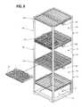
- FIG. 7is a pictorial view of the housing of the rack-mounted system of FIG. 1 without various components being mounted for illustration purposes;
- FIG. 8is a pictorial view of the housing of FIG. 7 illustrating the process of installation of fan/LAN trays;
- FIG. 9is an enlarged scale pictorial view of one embodiment of a fan/LAN tray for the rack-mounted system of FIG. 1;
- FIG. 9Ais an enlarged scale pictorial view of another embodiment of a fan/LAN tray for the rack-mounted system of FIG. 1;
- FIG. 9Bis an enlarged scale fragmentary pictorial view of the tray of FIG. 9A, illustrating some of the fans being removed;
- FIG. 10is a pictorial view of the housing of FIG. 7 with the fan/LAN trays installed;
- FIG. 11is a pictorial view of the housing of FIG. 7 illustrating the process of installation of blades
- FIG. 12is a fragmentary, enlarged scale front elevational view of the rack-mounted system of FIG. 1 illustrating the relative positioning of the fan/LAN trays and the blades;
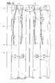
- FIG. 13is a diagrammatic, right-side elevational view of the rack-mounted system of FIG. 1 illustrating the configuration of the right-side cabling;
- FIG. 14is a bottom fragmentary pictorial view of the rack-mounted system of FIG. 1 illustrating the cabling in the front and right portion of the control bay;
- FIG. 15is a diagrammatic, left-side elevational view of the rack-mounted system of FIG. 1 illustrating the configuration of the left-side cabling;
- FIG. 16is a bottom fragmentary pictorial view of the rack-mounted system of FIG. 1 illustrating the cabling in the rear and left portion of the control bay;
- FIG. 17is an enlarged scale, fragmentary pictorial view of one embodiment of a power distribution unit (PDU) for the rack-mounted system of FIG. 1;
- PDUpower distribution unit
- FIG. 18is a front elevational view of the PDU shown in FIG. 17;
- FIG. 19is a fragmentary top view of the PDU shown in FIG. 17;
- FIG. 20is a rear elevational view of the PDU shown in FIG. 17;
- FIG. 21is a diagrammatic view of the rack-mounted system of FIG. 1 illustrating the flow of air therethrough;
- FIG. 22is a diagrammatic view of another embodiment of a rack-mounted system according to the present invention and illustrating the flow of air therethrough;
- FIG. 23is a diagrammatic view of yet another embodiment of a rack-mounted system according to the present invention and illustrating the flow of air therethrough;
- FIG. 24is a diagrammatic view of still another embodiment of a rack-mounted system according to the present invention and illustrating the flow of air therethrough;
- FIG. 25is an enlarged scale top view of one embodiment of a blade of the rack-mounted system of FIG. 1;
- FIG. 26is a left side elevational view of the blade of FIG. 1 ;
- an arrangement for cooling a series of closely spaced upright computer components mounted to a supportincluding a tray having a plurality of air moving devices such as fans. Members are used for helping mount removably the tray to the support in a generally horizontal disposition, and the air moving devices move air in a generally upright path of travel to help cool the upright computer components.
- the trayalso has a series of connector ports for connecting electrically to outputs from individual ones of the computer components.
- the trayincludes a front panel having the connector ports arranged in a row thereon.
- the front panelcan be opened to permit access to the air moving devices or removing them for repair or replacement.
- the air moving devicescan be removed from the support as a unit.
- the air moving devicesare arranged in separate sub groups and selected ones of the sub groups of air moving devices can be removed from the tray as a unit when the front panel is opened.
- electrical cablesconnect the connector ports for conveying signals therefrom, and the cables have a sufficient slack portion to permit the front panel to be removed to an open position while maintaining the electrical connection to the connector ports.
- the air moving devicesare “hot swappable” while the computer components remain in operation.
- a fan tray or unitwhich is adapted to be mounted horizontally within a rack to facilitate the movement of air vertically through computer components vertically mounted within the rack.
- a series of the fan traysare adapted to be disposed in a vertically-spaced apart manner within the rack. Each one is adapted to be removed and replaced, while permitting the computer components to continue to function normally.
- the rack mounted system 10includes a rack housing 12 configured generally as a rectangular box having a plurality of vertical bays 14 .
- the embodiment illustrated in the drawingsincludes three vertically spaced-apart bays 14 .
- Each bay 14is divided into a front bay portion 16 and a rear bay portion 18 by an intermediate transversely-extending horizontal divider 19 .
- the intermediate divider 19is most clearly illustrated in FIG. 7 .
- the bays 14are formed in the rack housing 12 in a vertical manner one above the other.
- a control bay 21is provided to house various controlled components, as hereinafter described in greater detail.
- the rack housing 12further includes a fan/LAN tray slot 23 above each bay 14 .
- Each fan/LAN tray slotis configured to accommodate a fan/LAN tray such as tray 27 .
- the embodiment illustrated in the drawingsprovides a control bay 21 (FIG. 7) having a bottom opening 25 (FIG. 7) for facilitating air flow to receive vertically moving air flow from a vent opening 26 in a floor 28 and vertically through the system 10 as assisted by the fan/LAN trays.
- a control bay 21FIG. 7
- a bottom opening 25FIG. 7
- an apertured top panel 26FIG. 1
- each bayis adapted to accommodate a plurality of computer components in the form of open structure computer components or blades, such as blade 32 (FIG. 1 ), in each of the front bay portion 16 and the rear bay portion 18 .
- blade 32FIG. 1
- eleven bladesmay be accommodated in each of the front bay and rear bay portions in a generally upright disposition.
- the system 10accommodates 66 computer components in a densely compact, closely spaced configuration.
- the bottom control bay 21is adapted to accommodate various control components. These control components may include a circuit breaker junction box 34 , as most clearly illustrated in FIG. 6 .
- the circuit breaker junction box 34is electrically connected to each PDU.
- a switch module 36is also provided in the control bay 21 .
- the switch module 36is adapted to control communication between the various blades, such as blade 32 , and a network, such as a local area network, wide area network, or a public network, such as the internet.
- the control bay 21accommodates an air intake fan module 38 (FIGS. 1 and 5) for facilitating intake of air through the bottom opening 25 and facilitating vertical air flow through the blades and the bays 14 and out the apertured top panel 26 .
- the embodiment of the rack system 10 illustrated in the figuresincludes four casters 41 for rollably supporting the system on the floor 26 (FIG. 5) for easy portability of the rack system 10 .
- Other embodiments of the rack system according to the present inventionmay be floor mounted, thereby including legs or skids in place of the casters for direct mounting to the floor.
- FIG. 9illustrates one embodiment of a fan/LAN tray 27 for mounting to a suitable support such as the rack system 10 illustrated in the drawings.
- the fan/LAN tray 27includes eight suitable air moving devices such as fans for facilitating vertical air flow. Although the embodiment illustrated in the drawings includes eight fans such as fan 43 (FIG. 9) per tray, any suitable number of fans may be used.
- each fan/LAN tray 27includes 12 LAN connector ports 45 , the end one of which may be used for test purposes. While 12 LAN connectors are shown in the disclosed embodiment, it should be understood that any number of such connectors may be employed for a given application.
- Internal wiring leads (not shown) from each LAN connector port 45extend to one of two signal connectors 47 (FIG. 9) in the back portion of the fan/LAN tray 27 .
- each signal connector 47is a 50 pin signal connector, and is connected electrically to the switch module 36 .
- each fan/LAN trayincludes a AC power inlet 49 in the back portion for providing power to the fans. When installed, power may be supplied to the fans such as fan 43 through the AC power inlet 49 from the PDU 29 , as hereinafter described in greater detail.
- each fan/LAN tray 27occupies an area directly above either the front bay portion 16 or the rear bay portion 18 . Accordingly, a fan/LAN tray in the front and a fan/LAN tray in the rear may completely cover each bay 14 level.
- a total of 6 fan/LAN trays 27in addition to the air intake fan module 38 may be provided in a three bay level rack mounted system 10 according to one embodiment of the present invention.
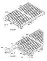
- a fan/LAN tray 42which is similar to the fan/LAN tray 27 , may be divided into a plurality of separate trays or tray portions such as a tray portion 44 , each of which can be removed independently so that the remaining tray portion or portions can continue to function.
- the LAN connectionsare separate from the fan tray or tray portions so that the tray portions may be removed independently of the LAN component.
- the fan tray 42includes a generally rectangular flat hollow frame 46 having a series of guides such as guide 68 for helping to mount the fan tray 42 to a suitable support (not shown), which may be similar to the rack housing 12 of FIG. 1 .
- the frame 46includes a front opening 48 (FIG. 9B) for receiving the individual tray portions such as the tray portion 44 .
- a removable front panel 51fits over the opening 48 and is secured in place by any suitable technique such as by using fastening devices (not shown).
- a series of connector portssuch as a connector port 53 are mounted on the front panel 51 and are electrically connected to signal connectors (not shown) which may be similar to the signal connectors 47 of FIG. 9 .
- cablessuch as a cable 55 are connected individually to the connector ports such as the connector port 53 .
- the cablessuch as the cable 55 include cable slack portions such as a cable slack portion 57 to enable the front panel 51 to be removed from the frame 46 , while permitting the electrical connections to the computer components to remain intact for normal operation of the system.
- individual ones of the fan tray portionscan be removed for repair or replacement, and the remaining fan tray portions can function independently to facilitate cooling, while the computer components remain in normal operation.
- the tray portion 44includes a front flange 59 to facilitate grasping by a user to pull it outwardly from the interior of the frame 46 as indicated in FIG. 9 B.
- the fan tray portionincludes a pair of air moving devices such as a fan 70 , and a power inlet (not shown) similar to the power inlet 49 of FIG. 9 to engage a power outlet 60 on a power distribution unit 62 for energizing the fans. In this manner, the tray portion 44 can be pulled out of the frame 46 by merely disengaging it from the power outlet 60 .
- Another like fan tray portioncan then be inserted in its place and connected to the power outlet 60 and then the front panel 51 can then be replaced over the opening 48 .
- the group of air moving devicescan be arranged in subgroups of tray portions so that some but not all of the air moving devices can be removed without interfering with the operation of the remaining devices.
- the subgroupscan be any number of one or more of the air moving devices.
- the individual tray portionssuch as the tray portion 44 can be positioned behind the front panel 51 , and a similar set of tray portions (not shown) can be installed to the rear portion of the frame 46 and interconnect with the power distribution unit 62 .
- a rear panel(not shown) is removable and is similar to the front panel 51 and serves the same purpose as the front
- Each bladeis provided with a pair of handles 54 projecting from the front face of a front panel.
- the front panelextends transversely to a rigid upright support or plate and is connected to the front edge of the support in an L-shaped configuration.
- the handlesallow a user to easily manipulate the blade 32 to be grasped by the user to slide the blade into or out of its bay.
- Each blade 32may include one or more mother boards 56 .
- each blade 32includes two mother boards 56 a , 56 b .
- the number of mother boards included in each blade 32may be varied according to design.
- the mother boardmay include heat sinks such as heat sinks 58 and 59 for facilitating the cooling of the mother boards. Further, each mother board is provided with random access memory (RAM) 61 . The amount of RAM 61 provided for each mother board may be varied as needed.
- a pair of power supply 63 a , 63 bmay be provided on the blade 32 for supplying power to their corresponding mother boards 56 a , 56 b .
- a pair of hard disks 64 a , 64 bmay also be provided on the blade 32 .
- Each blade 32includes a cut-out corner portion or section 65 in its upper back portion.
- the cut-out portion 65is sized to receive and accommodate the PDU 29 therebetween such that two opposing blades 32 and 32 a (as shown in FIG. 26) accommodate the PDU 29 almost completely.
- a substantially zero footprintis achieved for the PDU 29 .
- Each blade 32is provided with an AC power inlet such as an inlet 67 at or near the cut-out portion 65 .
- the AC power inlet 67engages electrically a corresponding AC connector such as a connector 76 (FIG. 17) of the PDU 29 .
- the installation of the blade 32may be achieved in a fast and efficient manner.
- the blade 32is simply slid into either the front bay portion 16 or the rear bay portion 18 of a bay 14 of the rack housing 12 .
- Each blade 32is slid back until its AC power inlet 67 engages a corresponding AC connector 76 on the PDU 29 .
- the intermediate dividers 119serve as a back stop for the blades 32 .
- Each blade 32is secured in its slot by four blade screws 69 , which attach the blade 32 to the rack housing 12 .
- a short blade/LAN connector cablesuch as a cable 45 (FIG. 12) or a cable 71 (FIG. 1) provides electrical networking connection between the blade 32 and a network such as a local area network, wide area network or a public network such as the internet.
- the mother boardsare each mounted at the front of each blade, and thus access thereto is readily available at front outlets such as at outlet 73 (FIG. 12 ).
- a data connectioncan be made from the outlet 73 , through a short cable 45 , an inlet 77 of a PDU 29 , which is coupled to the switch module 36 .
- the PDU 29supplies power from an external power source, through the circuit breaker junction box 34 , to the various blades 32 and the fan/LAN trays 27 .
- Each PDU 29includes an elongated PDU body 74 , which preferably is formed of a two piece, 18 gauge steel chassis.
- Each of two sides of the PDU body 74includes a series of female AC connectors 76 .
- each sideis provided with 12 female AC connectors 76 .
- the twelve connectors 76correspond to eleven blades mounted in the front bay portion 16 and the rear bay portion 18 of each bay 14 and a fan/LAN tray 27 .
- the twelfth connectoris for an AC power outlet on the front of the fan tray.
- each set of twelve female AC connectors 76receives power through a pair of power cables 72 .
- the power cable 72is a 15 amp power cable with strained relief near its junction with the PDU body 74 .
- the power cables 72are routed to the circuit breaker junction box 34 in the control bay 21 .
- the PDU body 74may also include a series of mounting studs 78 for installation of the PDU body 74 to the rack housing 12 .
- the power cables 72 from the PDU's 29 at each bay levelare directed along the right side of the rack housing 12 toward the front portion of the rack housing 12 and to the bottom, where they are connected electrically to the circuit breaker junction box 34 .
- the circuit breaker junction box 34the circuit breaker junction box 34 .
- a set of three cables generally indicated at 80are each adapted to be coupled to a suitable source of AC power to supply power to the system 10 .
- a set of six LAN cables 81 from the fan/LAN trays and PDUsare routed along the rear right side of the rack housing 12 to the switch module 36 .
- two LAN cables 81extend from each PDU which, in turn, are connected electrically to a pair of fifty pin signal connectors 47 .
- six such cables 81are directed along the right side of the rack housing 12 .
- six LAN cables 81extend from the fan/LAN trays 27 and PDUs along the left front side of the rack housing 12 .
- These six cables 81are also connected at their lower ends to the switch module 36 .
- a fully assembled and efficient rack mounted systemis provided.
- networking of the various components provided on the blades 32is also performed efficiently.
- eleven bladesare accommodated at each of the front bay portion 16 and the rear bay portion 18 at each bay 14 .
- 66such blades 32 may be accommodated.
- some of the slotsmay be occupied by master computer components or blades such as the master blades indicated at 32 a in FIGS. 4 and 6.
- two master blades 32 aare provided in the bottom of the three blade bays directly above the switch module 36 .
- the master blades 32 aare connected electrically directly to the switch module 36 via high speed connections (not shown) such as fiber optic connections.
- the master bladescontrol the switch module 36 to switch communication between the various slave blades 32 and the master blades.
- 64 slave bladesmay be accommodated by the illustrated embodiment of the system.
- Each of the 64 slave bladesmay be hot swappable, for example, allowing replacement of the blades 32 without causing the shutting down of the system 10 .
- Each fan/LAN tray 27is provided with twelve LAN connector ports such as the port 45 (FIG. 1 ). Eleven of the 12 LAN connector ports 45 are adapted to permit communication between the various slave blades 32 and the switch module 36 .
- the twelfth LAN connector port 45allows an external user to connect an external device such as a laptop computer to the network. Further, each fan/LAN tray 27 is provided with a centrally disposed AC power outlet for connecting such an external device.
- the system 10 illustrated in the figuresprovides efficient air flow to maintain a cool operating temperature for the various components mounted on the blades 32 .
- Air flowis directed from the bottom opening 25 by the air intake fan module 38 located in the control bay 21 .
- the air intake fan module 38directs the air flow vertically through the various open structure blades 32 at each bay level 14 .
- the air flowis further facilitated by the fans 43 in each fan/LAN tray 27 to move the air in its upwardly directed path of travel.
- the air flowis directed out of the rack housing 12 through the apertured top panel 26 .
- FIGS. 21 through 24illustrate further embodiments of the present invention.
- the intake and exhaust of the air flowmay be varied to accommodate various configurations as to the availability of air supply in the immediate environment.
- an air intake fan module 38 adraws air from a bottom opening 25 a , similar to that illustrated in the embodiment shown in FIGS. 1 through 21.
- Air flowis directed vertically with the aid of fans 43 a mounted on fan/LAN trays.
- the air flowis re-directed from a vertical path of travel at right angles to a horizontal path of travel out of the rack system 10 a towards the rear of the rack housing.
- An air flow hood 85 afacilitates the rearward re-direction of the air flow.
- FIG. 23illustrates yet another embodiment of the rack system according to the present invention.
- an air intake fan module 38 bdraws air horizontally inwardly through an opening such as defined by a perforated plate 87 b in the bottom front portion of the rack housing. The air flow is then re-directed upwardly with the aid of fans 43 b mounted in fan/LAN trays. The air flow is directed vertically out of the top portion of rack system 10 b.
- an air intake fan module 38 cdraws air horizontally through an opening such as defined by a perforated plate 87 c in the front bottom portion of the rack housing.
- the air flowis re-directed vertically through this system with the aid of fans 43 c .
- the air flowis re-directed at right angles to a horizontal path of travel out of the rack housing rearwardly at the top of the rack housing.
- the rearward redirection of the air flowis facilitated by an airflow hood 85 c .
Landscapes
- Engineering & Computer Science (AREA)
- Theoretical Computer Science (AREA)
- General Engineering & Computer Science (AREA)
- Physics & Mathematics (AREA)
- Computer Hardware Design (AREA)
- Human Computer Interaction (AREA)
- General Physics & Mathematics (AREA)
- Microelectronics & Electronic Packaging (AREA)
- Power Engineering (AREA)
- Thermal Sciences (AREA)
- Cooling Or The Like Of Electrical Apparatus (AREA)
Abstract
Description
| PATENT NO. | INVENTOR | ISSUE DATE | ||
| 4,258,967 | Boudreau | Mar. 31, 1081 | ||
| 4,879,634 | Storrow et al. | Nov. 07, 1989 | ||
| 4,977,532 | Borkowicz et al. | Dec. 11, 1990 | ||
| 5,010,444 | Storrow et al. | Apr. 23, 1991 | ||
| 5,216,579 | Basara et al. | Jun. 01, 1993 | ||
| 5,460,441 | Hastings et al. | Oct. 24, 1995 | ||
| 5,571,256 | Good et al. | Nov. 05, 1996 | ||
| 5,684,671 | Hobbs et al. | Nov. 04, 1997 | ||
| 5,877,938 | Hobbs et al. | Mar. 02, 1999 | ||
| 5,896,273 | Varghese et al. | Apr. 30, 1999 | ||
| 6,025,989 | Ayd et al. | Feb. 15, 2000 | ||
| 6,058,025 | Ecker et al. | May 02, 2000 | ||
| 6,075,698 | Hogan et al. | Jun. 13, 2000 | ||
| 6,220,456 B1 | Jensen et al. | Apr. 24, 2001 | ||
| 6,305,556 B1 | Mayer | Oct. 23, 2001 | ||
| 6,315,249 B1 | Jensen et al. | Nov. 13, 2001 | ||
| 6,325,636 B1 | Hipp et al. | Dec. 04, 2001 | ||
| Re. 35,915 | Hastings et al. | Oct. 06, 1998 | ||
| Des. 407,358 | Belanger et al. | Mar. 30, 1999 | ||
Claims (10)
Priority Applications (20)
| Application Number | Priority Date | Filing Date | Title |
|---|---|---|---|
| US10/449,608US6801428B2 (en) | 2002-05-31 | 2003-05-29 | Rack mountable computer component fan cooling arrangement and method |
| KR1020067015140AKR100913512B1 (en) | 2002-05-31 | 2003-05-30 | A cooling arrangement for cooling computer components |
| JP2004510300AJP2006512627A (en) | 2002-05-31 | 2003-05-30 | Method and apparatus for mounting computer components |
| CNA038126184ACN1739326A (en) | 2002-05-31 | 2003-05-30 | Method and apparatus for installing computer components |
| KR1020067015139AKR100913511B1 (en) | 2002-05-31 | 2003-05-30 | A heat sink for an active component |
| PCT/US2003/017328WO2003103359A1 (en) | 2002-05-31 | 2003-05-30 | Methods and apparatus for mounting computer components |
| CN2008101093563ACN101520680B (en) | 2002-05-31 | 2003-05-30 | Method and device for mounting computer component |
| KR1020047019513AKR100772084B1 (en) | 2002-05-31 | 2003-05-30 | Computer component structure and its manufacturing method |
| KR1020067015141AKR100913513B1 (en) | 2002-05-31 | 2003-05-30 | A power distribution unit for supplying electrical power to upright computer blades |
| EP03756355AEP1532852A1 (en) | 2002-05-31 | 2003-05-30 | Methods and apparatus for mounting computer components |
| CA2488037ACA2488037C (en) | 2002-05-31 | 2003-05-30 | Methods and apparatus for mounting computer components |
| KR1020067015138AKR100911700B1 (en) | 2002-05-31 | 2003-05-30 | A rack system for mounting components |
| AU2003243365AAU2003243365A1 (en) | 2002-05-31 | 2003-05-30 | Methods and apparatus for mounting computer components |
| EP04751511AEP1668968A2 (en) | 2003-05-08 | 2004-05-07 | Compact electronic component system and method |
| PCT/US2004/014145WO2004102324A2 (en) | 2003-05-08 | 2004-05-07 | Compact electronic component system and method |
| US10/928,577US20050024825A1 (en) | 2002-05-31 | 2004-08-27 | Rack mountable computer component fan cooling arrangement and method |
| JP2007337960AJP2008102965A (en) | 2002-05-31 | 2007-12-27 | Method and device for mounting computer components |
| JP2007337958AJP2008102964A (en) | 2002-05-31 | 2007-12-27 | Method and device for mounting computer components |
| JP2007337961AJP4747161B2 (en) | 2002-05-31 | 2007-12-27 | Method and apparatus for mounting computer components |
| JP2007337959AJP2008140406A (en) | 2002-05-31 | 2007-12-27 | Method and device for mounting computer component |
Applications Claiming Priority (5)
| Application Number | Priority Date | Filing Date | Title |
|---|---|---|---|
| US38500502P | 2002-05-31 | 2002-05-31 | |
| US38498702P | 2002-05-31 | 2002-05-31 | |
| US38499602P | 2002-05-31 | 2002-05-31 | |
| US38498602P | 2002-05-31 | 2002-05-31 | |
| US10/449,608US6801428B2 (en) | 2002-05-31 | 2003-05-29 | Rack mountable computer component fan cooling arrangement and method |
Related Child Applications (1)
| Application Number | Title | Priority Date | Filing Date |
|---|---|---|---|
| US10/928,577DivisionUS20050024825A1 (en) | 2002-05-31 | 2004-08-27 | Rack mountable computer component fan cooling arrangement and method |
Publications (2)
| Publication Number | Publication Date |
|---|---|
| US20030223196A1 US20030223196A1 (en) | 2003-12-04 |
| US6801428B2true US6801428B2 (en) | 2004-10-05 |
Family
ID=29587919
Family Applications (2)
| Application Number | Title | Priority Date | Filing Date |
|---|---|---|---|
| US10/449,608Expired - LifetimeUS6801428B2 (en) | 2002-05-31 | 2003-05-29 | Rack mountable computer component fan cooling arrangement and method |
| US10/928,577AbandonedUS20050024825A1 (en) | 2002-05-31 | 2004-08-27 | Rack mountable computer component fan cooling arrangement and method |
Family Applications After (1)
| Application Number | Title | Priority Date | Filing Date |
|---|---|---|---|
| US10/928,577AbandonedUS20050024825A1 (en) | 2002-05-31 | 2004-08-27 | Rack mountable computer component fan cooling arrangement and method |
Country Status (1)
| Country | Link |
|---|---|
| US (2) | US6801428B2 (en) |
Cited By (38)
| Publication number | Priority date | Publication date | Assignee | Title |
|---|---|---|---|---|
| US20030221817A1 (en)* | 2002-05-31 | 2003-12-04 | Racksaver, Inc. | Rack mountable computer component cooling method and device |
| US20040059903A1 (en)* | 2002-09-25 | 2004-03-25 | Smith John V. | Control system and method for rack mounted computer units |
| US20040184233A1 (en)* | 2003-02-20 | 2004-09-23 | Fujitsu Limited | Cooling structure of electronic equipment and information processing equipment using the cooling structure |
| US20040207983A1 (en)* | 2003-04-18 | 2004-10-21 | Cheng-Yi Lu | Heat dissipation module with twin centrifugal fans |
| US20040228090A1 (en)* | 2003-05-15 | 2004-11-18 | Blackwell Donald A. | Housing for hot pluggable network taps |
| US20050083651A1 (en)* | 2002-05-31 | 2005-04-21 | Smith John V. | Method and apparatus for rack mounting computer components |
| WO2004102324A3 (en)* | 2003-05-08 | 2005-05-12 | Verari Systems Inc | Compact electronic component system and method |
| US20050133200A1 (en)* | 2003-12-17 | 2005-06-23 | Malone Christopher G. | One or more heat exchanger components in major part operably locatable outside computer chassis |
| US7042720B1 (en)* | 2002-07-11 | 2006-05-09 | Storage Technology Corporation | Modular multiple disk drive apparatus |
| US20060203433A1 (en)* | 2005-03-08 | 2006-09-14 | Peterson Martha G | DC power port in a rack |
| US20060203450A1 (en)* | 2005-03-08 | 2006-09-14 | Intel Corporation | Heatsink |
| US20060215363A1 (en)* | 2005-03-23 | 2006-09-28 | Intel Corporation | Airflow redistribution device |
| US20060237208A1 (en)* | 2005-04-25 | 2006-10-26 | Elma Electronic Inc. | Electrical enclosure including accessible fan tray assembly |
| US7187547B1 (en)* | 2003-09-09 | 2007-03-06 | Emc Corporation | Techniques for cooling a set of circuit boards within a rack mount cabinet |
| US20080180903A1 (en)* | 2007-01-31 | 2008-07-31 | Sylvio Bisson | Cooling high performance computer systems |
| US7535861B2 (en) | 2005-10-07 | 2009-05-19 | Pacific Star Communications Inc. | Self-contained portable broadband communication system |
| US7573713B2 (en) | 2005-09-13 | 2009-08-11 | Pacific Star Communications | High velocity air cooling for electronic equipment |
| US20090255653A1 (en)* | 2008-04-11 | 2009-10-15 | Dell Products L.P. | System and Method for Cooling a Rack |
| WO2009134251A1 (en)* | 2008-04-30 | 2009-11-05 | Hewlett-Packard Development Company, L.P. | Power supply assembly for server rack and method for mounting power supply for server rack |
| US20090322192A1 (en)* | 2008-06-27 | 2009-12-31 | Sun Microsystems, Inc. | Aerodynamic structural safety barrier design |
| US20100165565A1 (en)* | 2008-12-31 | 2010-07-01 | Hellriegal Stephen V R | Data center |
| US7817589B2 (en) | 2006-02-21 | 2010-10-19 | Pacific Star Communications, Inc. | Self-contained portable broadband communications system |
| US20110044799A1 (en)* | 2009-08-18 | 2011-02-24 | Nidec Corporation | Fan apparatus |
| US7898799B2 (en) | 2008-04-01 | 2011-03-01 | Cray Inc. | Airflow management apparatus for computer cabinets and associated methods |
| US20110058334A1 (en)* | 2009-09-10 | 2011-03-10 | Nidec Corporation | Fan apparatus, electronic device, and fan-attached case |
| US8081459B2 (en) | 2008-10-17 | 2011-12-20 | Cray Inc. | Air conditioning systems for computer systems and associated methods |
| US8170724B2 (en) | 2008-02-11 | 2012-05-01 | Cray Inc. | Systems and associated methods for controllably cooling computer components |
| US20120306335A1 (en)* | 2011-06-03 | 2012-12-06 | Kendall Howard L.L.C. | Corner-Mount Electronics Cabinet |
| US8472181B2 (en) | 2010-04-20 | 2013-06-25 | Cray Inc. | Computer cabinets having progressive air velocity cooling systems and associated methods of manufacture and use |
| US20130170138A1 (en)* | 2011-12-28 | 2013-07-04 | Fujitsu Limited | Electronic device having cooling unit |
| US8820395B2 (en) | 2007-12-17 | 2014-09-02 | Cray Inc. | Cooling systems and heat exchangers for cooling computer components |
| US9615480B2 (en)* | 2015-07-30 | 2017-04-04 | Seagate Technology Llc | Storage device assembly |
| US9661782B2 (en) | 2012-03-30 | 2017-05-23 | International Business Machines Corporation | Data center cooling arrangements |
| US9706687B1 (en) | 2014-06-30 | 2017-07-11 | EMC IP Holding Company LLC | Electronic equipment chassis having storage devices and other modules configured for front-access removability |
| US10398060B1 (en)* | 2014-03-17 | 2019-08-27 | Amazon Technologies, Inc. | Discrete cooling module |
| USRE48135E1 (en)* | 2011-08-11 | 2020-07-28 | Quanta Computer Inc. | Server system |
| US11531383B1 (en) | 2020-09-30 | 2022-12-20 | Amazon Technologies, Inc. | Mist cooling for computer systems |
| US12382607B1 (en) | 2023-05-02 | 2025-08-05 | Amazon Technologies, Inc. | Liquid immersion chassis liner |
Families Citing this family (38)
| Publication number | Priority date | Publication date | Assignee | Title |
|---|---|---|---|---|
| US6487080B2 (en)* | 2000-09-22 | 2002-11-26 | Linux Networx, Inc. | Sub rack based vertical housing for computer systems |
| WO2004114240A2 (en)* | 2003-06-13 | 2004-12-29 | Xtec, Incorporated | Differential radio frequency identification reader |
| US7408772B2 (en)* | 2004-05-14 | 2008-08-05 | Hewlett-Packard Development Company, L.P. | Fan tray electronics enclosure |
| JP4673019B2 (en)* | 2004-09-10 | 2011-04-20 | 日立コンピュータ機器株式会社 | Information processing device |
| RU2305858C2 (en)* | 2005-09-16 | 2007-09-10 | Борис Алексеевич Хозяинов | Equipment conditioning system and controller for equipment conditioning system |
| US7430117B2 (en)* | 2005-12-14 | 2008-09-30 | Flextronics Ap, Llc | Airflow system for electronics chassis |
| US7542268B2 (en)* | 2006-03-17 | 2009-06-02 | Eaton Corporation | Modular electronic systems and methods using flexible power distribution unit interface |
| WO2007109683A2 (en)* | 2006-03-20 | 2007-09-27 | Flextronics Ap, Llc | Increasing air inlet/outlet size for electronics chassis |
| US7595985B2 (en) | 2006-06-19 | 2009-09-29 | Panduit Corp. | Network cabinet with thermal air flow management |
| US8328026B2 (en)* | 2007-02-22 | 2012-12-11 | Tellabs Operations, Inc. | Apparatus and method for configuring a dual rack-mountable chassis |
| US9141154B2 (en)* | 2007-11-07 | 2015-09-22 | Lenovo Enterprise Solutions (Singapore) Pte. Ltd. | Data communications and power distribution in a computer equipment rack |
| CN102007827B (en)* | 2008-04-14 | 2014-01-29 | 惠普开发有限公司 | Fan for computer element in the service position |
| DE102008026538B4 (en)* | 2008-06-03 | 2010-05-27 | Fujitsu Siemens Computers Gmbh | Server system and for use in the server system suitable server and suitable connection module |
| KR101239562B1 (en)* | 2008-07-25 | 2013-03-05 | 후지쯔 가부시끼가이샤 | Electronic device |
| TW201124053A (en)* | 2009-12-30 | 2011-07-01 | Hon Hai Prec Ind Co Ltd | Server rack, server device and data center |
| EP2638607B1 (en)* | 2010-11-09 | 2019-03-20 | Server Technology, Inc. | Equipment-rack power distribution system with cooling |
| JP5315323B2 (en)* | 2010-11-17 | 2013-10-16 | アラクサラネットワークス株式会社 | Electronic equipment |
| US8390998B2 (en) | 2010-12-01 | 2013-03-05 | Cisco Technology, Inc. | Configurable fan unit |
| US9017020B2 (en) | 2011-02-28 | 2015-04-28 | Cisco Technology, Inc. | Configurable fan unit |
| GB2506017B (en)* | 2011-05-25 | 2015-11-04 | Hewlett Packard Development Co | Blade computer system |
| EP2790479B1 (en)* | 2013-04-12 | 2016-10-12 | Pentair Technical Solutions GmbH | Housing for installing electronic plug-in cards |
| CN104423457A (en)* | 2013-09-11 | 2015-03-18 | 鸿富锦精密电子(天津)有限公司 | Electronic device and fixing rack thereof |
| US9532484B2 (en)* | 2013-11-20 | 2016-12-27 | Ara Usa Llc | Rack for mounting and storage of electronic equipment |
| US10004162B2 (en)* | 2013-12-23 | 2018-06-19 | Dell Products, L.P. | Enhanced fan design, configuration, and control for modular, scalable and expandable, rack-based information handling system |
| TWI537712B (en)* | 2015-01-19 | 2016-06-11 | 圓展科技股份有限公司 | Charging device and power supply structure and bearing module thereof |
| US10039211B2 (en) | 2015-03-09 | 2018-07-31 | Vapor IO Inc. | Rack for computing equipment |
| US9839162B2 (en) | 2015-03-09 | 2017-12-05 | Vapor IO Inc. | Cooling system for data center rack |
| US9454189B1 (en)* | 2015-04-16 | 2016-09-27 | Quanta Computer Inc. | Systems and methods for distributing power in a server system |
| US10454772B2 (en) | 2015-10-30 | 2019-10-22 | Vapor IO Inc. | Compact uninteruptable power supply |
| CN205249640U (en)* | 2015-12-10 | 2016-05-18 | 日月元科技(深圳)有限公司 | Industrial UPS machine case structure |
| EP3310139B1 (en) | 2016-10-11 | 2019-09-04 | Pentair Technical Solutions GmbH | Module holder |
| US20180175646A1 (en)* | 2016-12-15 | 2018-06-21 | Chen-Source Inc. | Charging cabinet |
| CN107801345B (en)* | 2017-10-30 | 2023-12-19 | 浙江一舟电子科技股份有限公司 | Refrigerator type integrated data center |
| US11129294B2 (en)* | 2018-11-15 | 2021-09-21 | CFW Investments LLC | Modular rack assembly |
| US10952353B1 (en)* | 2019-08-21 | 2021-03-16 | Schneider Electric It Corporation | Thermal buffering module for equipment rack |
| GB2604345B (en)* | 2021-03-01 | 2023-03-22 | Etl Systems Ltd | Modular electronic apparatus for distribution of satellite signals |
| US11653758B1 (en)* | 2023-02-01 | 2023-05-23 | Union Hospital, Tongji Medical College, Huazhong University Of Science And Technology | Hospital human resource information management file cabinet |
| US20240276125A1 (en)* | 2023-02-09 | 2024-08-15 | Level 3 Communications, Llc | Telecommunications equipment shelf with integrated power and cooling |
Citations (44)
| Publication number | Priority date | Publication date | Assignee | Title |
|---|---|---|---|---|
| US3858093A (en)* | 1973-09-14 | 1974-12-31 | Gte Automatic Electric Lab Inc | An arrangement for combining high and low level signals within a single frame with a noise separating fuse panel |
| US3868158A (en) | 1972-05-17 | 1975-02-25 | Honeywell Bull Sa | Module rack for connection boxes of printed-circuit cards |
| US4258967A (en) | 1979-11-02 | 1981-03-31 | Digital Equipment Corporation | Integral pivot and lock apparatus for slide rack mounted boxes |
| JPS576296A (en) | 1980-06-13 | 1982-01-13 | Nissan Motor Co Ltd | Heat accumulator |
| JPS57128194A (en) | 1981-02-02 | 1982-08-09 | Sabun Kogyosho Kk | Manufacture of intermediate unit pattern for sewing machine |
| WO1986003089A1 (en) | 1984-11-15 | 1986-05-22 | Fujitsu Limited | Cooling structure of a rack for electronic devices |
| JPS6273592A (en) | 1985-09-27 | 1987-04-04 | 高周波熱錬株式会社 | Secondary inductor combination type induction heating coil for heating crankshaft with small shoulder |
| US4672509A (en)* | 1986-08-07 | 1987-06-09 | Ncr Corporation | Air cooling assembly in an electronic system enclosure |
| US4699270A (en) | 1985-09-09 | 1987-10-13 | The Union Corporation | Modular packaging system |
| JPS6350196A (en) | 1986-08-19 | 1988-03-03 | Matsushita Electric Ind Co Ltd | Diaphragm for speaker |
| US4748540A (en)* | 1987-04-24 | 1988-05-31 | Honeywell Bull Inc. | Compact packaging of electronic equipment within a small profile enclosure |
| US4879634A (en) | 1987-11-13 | 1989-11-07 | Plessey Overseas Limited | Rack mounted circuit board |
| US4977532A (en) | 1988-04-06 | 1990-12-11 | Xycom, Inc. | Industrial computer system with removable equipment drawer |
| US5010444A (en) | 1987-11-13 | 1991-04-23 | Radstone Technology Limited | Rack mounted circuit board |
| JPH03164999A (en) | 1989-11-24 | 1991-07-16 | Fujitsu Ltd | Housing with fire alarm |
| JPH0428496U (en) | 1990-06-28 | 1992-03-06 | ||
| US5216579A (en) | 1992-01-29 | 1993-06-01 | International Business Machines Corporation | Rack based packaging system for computers with cable, cooling and power management module |
| JPH05183282A (en) | 1992-01-06 | 1993-07-23 | Fujitsu Ltd | Electronic device cooling method |
| US5460441A (en) | 1994-11-01 | 1995-10-24 | Compaq Computer Corporation | Rack-mounted computer apparatus |
| JPH07312494A (en) | 1994-05-19 | 1995-11-28 | Fujitsu Ltd | Axial flow type fan and cooling structure for electronic equipment using the same |
| JPH0888489A (en) | 1994-09-19 | 1996-04-02 | Fujitsu Ltd | Electronic device with cooling structure |
| JPH08172287A (en) | 1994-12-19 | 1996-07-02 | Fujitsu Ltd | Fan unit |
| JPH08278834A (en) | 1995-04-07 | 1996-10-22 | Hitachi Ltd | Non-stop computer |
| US5570740A (en) | 1995-03-03 | 1996-11-05 | Dsc Communications Corporation | Built-in cooling system for an enclosure |
| US5571256A (en) | 1994-10-25 | 1996-11-05 | Compaq Computer Corporation | Server drawer slide mount apparatus for a rack-mounted computer system |
| US5684671A (en) | 1995-08-22 | 1997-11-04 | Sequent Computer Systems, Inc. | Packaging architecture for a data server |
| USRE35915E (en) | 1992-09-24 | 1998-10-06 | Compaq Computer Corporation | Apparatus for removably supporting a plurality of hot plug-connected hard disk drives |
| USD407385S (en) | 1997-02-12 | 1999-03-30 | Advanced Modular Solutions, Inc. | Rack for enclosing a rack mounted computer system |
| US5896273A (en) | 1996-12-31 | 1999-04-20 | Compaq Computer Corp. | Modular computer chassis interchangeable between stand alone and rack mounted states |
| JPH11135694A (en) | 1997-10-29 | 1999-05-21 | Hitachi Ltd | Electronic equipment cooling device |
| US5991163A (en) | 1998-11-12 | 1999-11-23 | Nexabit Networks, Inc. | Electronic circuit board assembly and method of closely stacking boards and cooling the same |
| US6025989A (en) | 1998-04-21 | 2000-02-15 | International Business Machines Corporation | Modular node assembly for rack mounted multiprocessor computer |
| US6058025A (en) | 1998-04-21 | 2000-05-02 | International Business Machines Corporation | Computer tailgate having expansion slot alignment pins |
| US6069797A (en) | 1998-12-29 | 2000-05-30 | Motorola, Inc. | Power distribution assembly |
| US6075698A (en) | 1998-10-27 | 2000-06-13 | Ads, The Power Resource, Inc. | Removable fan for rack mounted rectifiers |
| US6185098B1 (en) | 2000-01-31 | 2001-02-06 | Chatsworth Products, Inc. | Co-location server cabinet |
| US6220456B1 (en) | 2000-04-19 | 2001-04-24 | Dell Products, L.P. | Method and apparatus for supporting a computer chassis |
| US6305556B1 (en) | 2000-10-26 | 2001-10-23 | Hewlett-Packard Company | Cable management solution for rack-mounted computers |
| US6315249B1 (en) | 1999-12-29 | 2001-11-13 | Dell Usa, L.P. | System for managing cables for a rack-mounted computer system |
| US6325636B1 (en) | 2000-07-20 | 2001-12-04 | Rlx Technologies, Inc. | Passive midplane for coupling web server processing cards with a network interface(s) |
| US20020006026A1 (en) | 1999-05-31 | 2002-01-17 | Tsutomu Takahashi | Communications apparatus and plug-in unit |
| US6487080B2 (en)* | 2000-09-22 | 2002-11-26 | Linux Networx, Inc. | Sub rack based vertical housing for computer systems |
| US6496366B1 (en) | 1999-10-26 | 2002-12-17 | Rackable Systems, Llc | High density computer equipment storage system |
| US6499609B2 (en) | 2001-06-04 | 2002-12-31 | Hyperchip Inc. | Compact shelf unit for electronic equipment rack |
- 2003
- 2003-05-29USUS10/449,608patent/US6801428B2/ennot_activeExpired - Lifetime
- 2004
- 2004-08-27USUS10/928,577patent/US20050024825A1/ennot_activeAbandoned
Patent Citations (47)
| Publication number | Priority date | Publication date | Assignee | Title |
|---|---|---|---|---|
| US3868158A (en) | 1972-05-17 | 1975-02-25 | Honeywell Bull Sa | Module rack for connection boxes of printed-circuit cards |
| US3858093A (en)* | 1973-09-14 | 1974-12-31 | Gte Automatic Electric Lab Inc | An arrangement for combining high and low level signals within a single frame with a noise separating fuse panel |
| US4258967A (en) | 1979-11-02 | 1981-03-31 | Digital Equipment Corporation | Integral pivot and lock apparatus for slide rack mounted boxes |
| JPS576296A (en) | 1980-06-13 | 1982-01-13 | Nissan Motor Co Ltd | Heat accumulator |
| JPS57128194A (en) | 1981-02-02 | 1982-08-09 | Sabun Kogyosho Kk | Manufacture of intermediate unit pattern for sewing machine |
| WO1986003089A1 (en) | 1984-11-15 | 1986-05-22 | Fujitsu Limited | Cooling structure of a rack for electronic devices |
| US4774631A (en) | 1984-11-15 | 1988-09-27 | Fujitsu Limited | Cooling structure of electronic equipment rack |
| US4699270A (en) | 1985-09-09 | 1987-10-13 | The Union Corporation | Modular packaging system |
| JPS6273592A (en) | 1985-09-27 | 1987-04-04 | 高周波熱錬株式会社 | Secondary inductor combination type induction heating coil for heating crankshaft with small shoulder |
| US4672509A (en)* | 1986-08-07 | 1987-06-09 | Ncr Corporation | Air cooling assembly in an electronic system enclosure |
| JPS6350196A (en) | 1986-08-19 | 1988-03-03 | Matsushita Electric Ind Co Ltd | Diaphragm for speaker |
| US4748540A (en)* | 1987-04-24 | 1988-05-31 | Honeywell Bull Inc. | Compact packaging of electronic equipment within a small profile enclosure |
| US4879634A (en) | 1987-11-13 | 1989-11-07 | Plessey Overseas Limited | Rack mounted circuit board |
| US5010444A (en) | 1987-11-13 | 1991-04-23 | Radstone Technology Limited | Rack mounted circuit board |
| US4977532A (en) | 1988-04-06 | 1990-12-11 | Xycom, Inc. | Industrial computer system with removable equipment drawer |
| JPH03164999A (en) | 1989-11-24 | 1991-07-16 | Fujitsu Ltd | Housing with fire alarm |
| JPH0428496U (en) | 1990-06-28 | 1992-03-06 | ||
| JPH05183282A (en) | 1992-01-06 | 1993-07-23 | Fujitsu Ltd | Electronic device cooling method |
| US5216579A (en) | 1992-01-29 | 1993-06-01 | International Business Machines Corporation | Rack based packaging system for computers with cable, cooling and power management module |
| USRE35915E (en) | 1992-09-24 | 1998-10-06 | Compaq Computer Corporation | Apparatus for removably supporting a plurality of hot plug-connected hard disk drives |
| JPH07312494A (en) | 1994-05-19 | 1995-11-28 | Fujitsu Ltd | Axial flow type fan and cooling structure for electronic equipment using the same |
| JPH0888489A (en) | 1994-09-19 | 1996-04-02 | Fujitsu Ltd | Electronic device with cooling structure |
| US5571256A (en) | 1994-10-25 | 1996-11-05 | Compaq Computer Corporation | Server drawer slide mount apparatus for a rack-mounted computer system |
| US5460441A (en) | 1994-11-01 | 1995-10-24 | Compaq Computer Corporation | Rack-mounted computer apparatus |
| JPH08172287A (en) | 1994-12-19 | 1996-07-02 | Fujitsu Ltd | Fan unit |
| US5570740A (en) | 1995-03-03 | 1996-11-05 | Dsc Communications Corporation | Built-in cooling system for an enclosure |
| JPH08278834A (en) | 1995-04-07 | 1996-10-22 | Hitachi Ltd | Non-stop computer |
| US5684671A (en) | 1995-08-22 | 1997-11-04 | Sequent Computer Systems, Inc. | Packaging architecture for a data server |
| US5877938A (en) | 1995-08-22 | 1999-03-02 | Sequent Computer Systems, Inc. | Packaging architecture for a data server |
| US5896273A (en) | 1996-12-31 | 1999-04-20 | Compaq Computer Corp. | Modular computer chassis interchangeable between stand alone and rack mounted states |
| USD407385S (en) | 1997-02-12 | 1999-03-30 | Advanced Modular Solutions, Inc. | Rack for enclosing a rack mounted computer system |
| JPH11135694A (en) | 1997-10-29 | 1999-05-21 | Hitachi Ltd | Electronic equipment cooling device |
| US6025989A (en) | 1998-04-21 | 2000-02-15 | International Business Machines Corporation | Modular node assembly for rack mounted multiprocessor computer |
| US6058025A (en) | 1998-04-21 | 2000-05-02 | International Business Machines Corporation | Computer tailgate having expansion slot alignment pins |
| US6075698A (en) | 1998-10-27 | 2000-06-13 | Ads, The Power Resource, Inc. | Removable fan for rack mounted rectifiers |
| US5991163A (en) | 1998-11-12 | 1999-11-23 | Nexabit Networks, Inc. | Electronic circuit board assembly and method of closely stacking boards and cooling the same |
| US6069797A (en) | 1998-12-29 | 2000-05-30 | Motorola, Inc. | Power distribution assembly |
| US20020006026A1 (en) | 1999-05-31 | 2002-01-17 | Tsutomu Takahashi | Communications apparatus and plug-in unit |
| US6552915B2 (en) | 1999-05-31 | 2003-04-22 | Fujitsu Limited | Communications apparatus and plug-in unit |
| US6496366B1 (en) | 1999-10-26 | 2002-12-17 | Rackable Systems, Llc | High density computer equipment storage system |
| US6315249B1 (en) | 1999-12-29 | 2001-11-13 | Dell Usa, L.P. | System for managing cables for a rack-mounted computer system |
| US6185098B1 (en) | 2000-01-31 | 2001-02-06 | Chatsworth Products, Inc. | Co-location server cabinet |
| US6220456B1 (en) | 2000-04-19 | 2001-04-24 | Dell Products, L.P. | Method and apparatus for supporting a computer chassis |
| US6325636B1 (en) | 2000-07-20 | 2001-12-04 | Rlx Technologies, Inc. | Passive midplane for coupling web server processing cards with a network interface(s) |
| US6487080B2 (en)* | 2000-09-22 | 2002-11-26 | Linux Networx, Inc. | Sub rack based vertical housing for computer systems |
| US6305556B1 (en) | 2000-10-26 | 2001-10-23 | Hewlett-Packard Company | Cable management solution for rack-mounted computers |
| US6499609B2 (en) | 2001-06-04 | 2002-12-31 | Hyperchip Inc. | Compact shelf unit for electronic equipment rack |
Non-Patent Citations (1)
| Title |
|---|
| Kojima, Yamazaki, Cooling System Using Heat Pipes, Advances in Electronic Packaging 1992, ASME. |
Cited By (70)
| Publication number | Priority date | Publication date | Assignee | Title |
|---|---|---|---|---|
| US7420805B2 (en)* | 2002-05-31 | 2008-09-02 | Verari Systems, Inc. | Method and apparatus for rack mounting computer components |
| US20050083651A1 (en)* | 2002-05-31 | 2005-04-21 | Smith John V. | Method and apparatus for rack mounting computer components |
| US20030221817A1 (en)* | 2002-05-31 | 2003-12-04 | Racksaver, Inc. | Rack mountable computer component cooling method and device |
| US7042720B1 (en)* | 2002-07-11 | 2006-05-09 | Storage Technology Corporation | Modular multiple disk drive apparatus |
| US20040059903A1 (en)* | 2002-09-25 | 2004-03-25 | Smith John V. | Control system and method for rack mounted computer units |
| US20040184233A1 (en)* | 2003-02-20 | 2004-09-23 | Fujitsu Limited | Cooling structure of electronic equipment and information processing equipment using the cooling structure |
| US7154748B2 (en)* | 2003-02-20 | 2006-12-26 | Fujitsu Limited | Cooling structure of electronic equipment and information processing equipment using the cooling structure |
| US20040207983A1 (en)* | 2003-04-18 | 2004-10-21 | Cheng-Yi Lu | Heat dissipation module with twin centrifugal fans |
| US7126818B2 (en)* | 2003-04-18 | 2006-10-24 | Delta Electronics, Inc. | Heat dissipation module with twin centrifugal fans |
| WO2004102324A3 (en)* | 2003-05-08 | 2005-05-12 | Verari Systems Inc | Compact electronic component system and method |
| US20040228090A1 (en)* | 2003-05-15 | 2004-11-18 | Blackwell Donald A. | Housing for hot pluggable network taps |
| US7187547B1 (en)* | 2003-09-09 | 2007-03-06 | Emc Corporation | Techniques for cooling a set of circuit boards within a rack mount cabinet |
| US20050133200A1 (en)* | 2003-12-17 | 2005-06-23 | Malone Christopher G. | One or more heat exchanger components in major part operably locatable outside computer chassis |
| US7273088B2 (en)* | 2003-12-17 | 2007-09-25 | Hewlett-Packard Development Company, L.P. | One or more heat exchanger components in major part operably locatable outside computer chassis |
| US20060203433A1 (en)* | 2005-03-08 | 2006-09-14 | Peterson Martha G | DC power port in a rack |
| US7274571B2 (en)* | 2005-03-08 | 2007-09-25 | Intel Corporation | Heatsink |
| US7355859B2 (en)* | 2005-03-08 | 2008-04-08 | Hewlett-Packard Development Company, L.P. | DC power port in a rack |
| US20060203450A1 (en)* | 2005-03-08 | 2006-09-14 | Intel Corporation | Heatsink |
| US7215552B2 (en)* | 2005-03-23 | 2007-05-08 | Intel Corporation | Airflow redistribution device |
| US20060215363A1 (en)* | 2005-03-23 | 2006-09-28 | Intel Corporation | Airflow redistribution device |
| US7312990B2 (en)* | 2005-04-25 | 2007-12-25 | Elma Electronic Inc. | Electrical enclosure including accessible fan tray assembly |
| US20060237208A1 (en)* | 2005-04-25 | 2006-10-26 | Elma Electronic Inc. | Electrical enclosure including accessible fan tray assembly |
| US7573713B2 (en) | 2005-09-13 | 2009-08-11 | Pacific Star Communications | High velocity air cooling for electronic equipment |
| US7535861B2 (en) | 2005-10-07 | 2009-05-19 | Pacific Star Communications Inc. | Self-contained portable broadband communication system |
| US7817589B2 (en) | 2006-02-21 | 2010-10-19 | Pacific Star Communications, Inc. | Self-contained portable broadband communications system |
| US8270325B2 (en) | 2006-02-21 | 2012-09-18 | Pacific Star Communications, Inc. | Mobile broadband communications system, such as a deployable self-contained portable system |
| US7813121B2 (en) | 2007-01-31 | 2010-10-12 | Liquid Computing Corporation | Cooling high performance computer systems |
| US20080180903A1 (en)* | 2007-01-31 | 2008-07-31 | Sylvio Bisson | Cooling high performance computer systems |
| US8320121B2 (en) | 2007-01-31 | 2012-11-27 | Liquid Computing Corporation | Cooling high performance computer systems |
| US20110080701A1 (en)* | 2007-01-31 | 2011-04-07 | Liquid Computing Corporation | Cooling high performance computer systems |
| US10082845B2 (en) | 2007-12-17 | 2018-09-25 | Cray, Inc. | Cooling systems and heat exchangers for cooling computer components |
| US9596789B2 (en) | 2007-12-17 | 2017-03-14 | Cray Inc. | Cooling systems and heat exchangers for cooling computer components |
| US9288935B2 (en) | 2007-12-17 | 2016-03-15 | Cray Inc. | Cooling systems and heat exchangers for cooling computer components |
| US8820395B2 (en) | 2007-12-17 | 2014-09-02 | Cray Inc. | Cooling systems and heat exchangers for cooling computer components |
| US10588246B2 (en) | 2008-02-11 | 2020-03-10 | Cray, Inc. | Systems and associated methods for controllably cooling computer components |
| US9420729B2 (en) | 2008-02-11 | 2016-08-16 | Cray Inc. | Systems and associated methods for controllably cooling computer components |
| US8170724B2 (en) | 2008-02-11 | 2012-05-01 | Cray Inc. | Systems and associated methods for controllably cooling computer components |
| US7898799B2 (en) | 2008-04-01 | 2011-03-01 | Cray Inc. | Airflow management apparatus for computer cabinets and associated methods |
| US20090255653A1 (en)* | 2008-04-11 | 2009-10-15 | Dell Products L.P. | System and Method for Cooling a Rack |
| US20110043986A1 (en)* | 2008-04-30 | 2011-02-24 | Conn Kevin D | Power supply assembly for server rack and method for mounting power supply for server rack |
| CN102017822B (en)* | 2008-04-30 | 2015-11-25 | 惠普开发有限公司 | For the power supply module of server cabinet and the method for build-in services device rack power supply |
| CN102017822A (en)* | 2008-04-30 | 2011-04-13 | 惠普开发有限公司 | Power supply assembly for server rack and method for mounting power supply for server rack |
| WO2009134251A1 (en)* | 2008-04-30 | 2009-11-05 | Hewlett-Packard Development Company, L.P. | Power supply assembly for server rack and method for mounting power supply for server rack |
| US20090322192A1 (en)* | 2008-06-27 | 2009-12-31 | Sun Microsystems, Inc. | Aerodynamic structural safety barrier design |
| US8081459B2 (en) | 2008-10-17 | 2011-12-20 | Cray Inc. | Air conditioning systems for computer systems and associated methods |
| US8537539B2 (en) | 2008-10-17 | 2013-09-17 | Cray Inc. | Air conditioning systems for computer systems and associated methods |
| US8833094B2 (en) | 2008-12-31 | 2014-09-16 | Cirrascale Corporation | Data center |
| US8842420B2 (en) | 2008-12-31 | 2014-09-23 | Cirrascale Corporation | Data center |
| US8842430B2 (en) | 2008-12-31 | 2014-09-23 | Cirrascale Corporation | Data center |
| US20100165565A1 (en)* | 2008-12-31 | 2010-07-01 | Hellriegal Stephen V R | Data center |
| US7990710B2 (en) | 2008-12-31 | 2011-08-02 | Vs Acquisition Co. Llc | Data center |
| US20110044799A1 (en)* | 2009-08-18 | 2011-02-24 | Nidec Corporation | Fan apparatus |
| US20110058334A1 (en)* | 2009-09-10 | 2011-03-10 | Nidec Corporation | Fan apparatus, electronic device, and fan-attached case |
| US9310856B2 (en) | 2010-04-20 | 2016-04-12 | Cray Inc. | Computer cabinets having progressive air velocity cooling systems and associated methods of manufacture and use |
| US8472181B2 (en) | 2010-04-20 | 2013-06-25 | Cray Inc. | Computer cabinets having progressive air velocity cooling systems and associated methods of manufacture and use |
| US8894161B2 (en)* | 2011-06-03 | 2014-11-25 | Kendall Howard L.L.C. | Corner-mount electronics cabinet |
| US20120306335A1 (en)* | 2011-06-03 | 2012-12-06 | Kendall Howard L.L.C. | Corner-Mount Electronics Cabinet |
| USRE48135E1 (en)* | 2011-08-11 | 2020-07-28 | Quanta Computer Inc. | Server system |
| US20130170138A1 (en)* | 2011-12-28 | 2013-07-04 | Fujitsu Limited | Electronic device having cooling unit |
| US9007764B2 (en)* | 2011-12-28 | 2015-04-14 | Fujitsu Limited | Electronic device having cooling unit |
| US9661782B2 (en) | 2012-03-30 | 2017-05-23 | International Business Machines Corporation | Data center cooling arrangements |
| US9826660B2 (en) | 2012-03-30 | 2017-11-21 | International Business Machines Corporation | Data center cooling arrangements |
| US9788456B2 (en) | 2012-03-30 | 2017-10-10 | International Business Machines Corporation | Data center cooling arrangements |
| US10398060B1 (en)* | 2014-03-17 | 2019-08-27 | Amazon Technologies, Inc. | Discrete cooling module |
| US11553626B2 (en) | 2014-03-17 | 2023-01-10 | Amazon Technologies, Inc. | Discrete cooling module |
| US10051764B1 (en) | 2014-06-30 | 2018-08-14 | EMC IP Holding Company LLC | Electronic equipment chassis having storage devices and other modules configured for front-access removability |
| US9706687B1 (en) | 2014-06-30 | 2017-07-11 | EMC IP Holding Company LLC | Electronic equipment chassis having storage devices and other modules configured for front-access removability |
| US9615480B2 (en)* | 2015-07-30 | 2017-04-04 | Seagate Technology Llc | Storage device assembly |
| US11531383B1 (en) | 2020-09-30 | 2022-12-20 | Amazon Technologies, Inc. | Mist cooling for computer systems |
| US12382607B1 (en) | 2023-05-02 | 2025-08-05 | Amazon Technologies, Inc. | Liquid immersion chassis liner |
Also Published As
| Publication number | Publication date |
|---|---|
| US20030223196A1 (en) | 2003-12-04 |
| US20050024825A1 (en) | 2005-02-03 |
Similar Documents
| Publication | Publication Date | Title |
|---|---|---|
| US6801428B2 (en) | Rack mountable computer component fan cooling arrangement and method | |
| US6909611B2 (en) | Rack mountable computer component and method of making same | |
| US7420805B2 (en) | Method and apparatus for rack mounting computer components | |
| US6836030B2 (en) | Rack mountable computer component power distribution unit and method | |
| CA2488037C (en) | Methods and apparatus for mounting computer components | |
| AU2015238911B2 (en) | Modular mass storage system | |
| EP0269479B1 (en) | A cabinet for a computer assembly | |
| CN109788700B (en) | Partial Width Rack Mount Computing Equipment | |
| US20090152216A1 (en) | Rack system providing flexible configuration of computer systems with front access | |
| US6748458B2 (en) | Modular input/output expansion system for an external computer | |
| US20040057216A1 (en) | Electronic component rack assembly and method | |
| US20030221817A1 (en) | Rack mountable computer component cooling method and device | |
| US20250311169A1 (en) | Airflow management system for power module | |
| US6842334B2 (en) | Portable diagnostic apparatus for computer components and systems and method of using same | |
| WO2004031037A2 (en) | Electronic component rack assembly and method |
Legal Events
| Date | Code | Title | Description |
|---|---|---|---|
| AS | Assignment | Owner name:RACKSAVER, INC., CALIFORNIA Free format text:ASSIGNMENT OF ASSIGNORS INTEREST;ASSIGNORS:SMITH, JOHN V.;HESTER, VICTOR P.;WYLIE, WILLIAM A.;REEL/FRAME:014366/0744 Effective date:20030529 | |
| DJ | All references should be deleted, no patent was granted | ||
| STCF | Information on status: patent grant | Free format text:PATENTED CASE | |
| AS | Assignment | Owner name:VERARI SYSTEMS, INC., CALIFORNIA Free format text:CHANGE OF NAME;ASSIGNOR:RACKSAVER, INC.;REEL/FRAME:015259/0392 Effective date:20040621 | |
| FEPP | Fee payment procedure | Free format text:PAYER NUMBER DE-ASSIGNED (ORIGINAL EVENT CODE: RMPN); ENTITY STATUS OF PATENT OWNER: SMALL ENTITY Free format text:PAYOR NUMBER ASSIGNED (ORIGINAL EVENT CODE: ASPN); ENTITY STATUS OF PATENT OWNER: SMALL ENTITY | |
| FPAY | Fee payment | Year of fee payment:4 | |
| AS | Assignment | Owner name:CARLYLE VENTURE PARTNERS II, L.P., CALIFORNIA Free format text:SECURITY AGREEMENT;ASSIGNOR:VERARI SYSTEMS, INC.;REEL/FRAME:022610/0283 Effective date:20090210 Owner name:CARLYLE VENTURE PARTNERS II, L.P.,CALIFORNIA Free format text:SECURITY AGREEMENT;ASSIGNOR:VERARI SYSTEMS, INC.;REEL/FRAME:022610/0283 Effective date:20090210 | |
| AS | Assignment | Owner name:CREDIT MANAGERS ASSOCIATION OF CALIFORNIA,CALIFORN Free format text:SECURED PARTY RELEASE OF LIEN BY CONSENT TO FILING UCC3 COLLATERAL RESTATEMENT;ASSIGNOR:CARLYLE VENTURE PARTNERS II, L.P.;REEL/FRAME:024515/0413 Effective date:20100114 Owner name:VERARI SYSTEMS, INC.,CALIFORNIA Free format text:SECURED PARTY CONSENT TO ASSIGNMENT FOR BENEFIT OF CREDITORS;ASSIGNOR:CARLYLE VENTURE PARTNERS II, L.P.;REEL/FRAME:024515/0426 Effective date:20091214 Owner name:CREDIT MANAGERS ASSOCIATION OF CALIFORNIA,CALIFORN Free format text:ASSIGNMENT OF ASSIGNORS INTEREST;ASSIGNOR:VERARI SYSTEMS, INC.;REEL/FRAME:024515/0429 Effective date:20091214 Owner name:VS ACQUISITION CO. LLC,CALIFORNIA Free format text:ASSIGNMENT OF ASSIGNORS INTEREST;ASSIGNOR:CREDIT MANAGERS ASSOCIATION OF CALIFORNIA;REEL/FRAME:024515/0436 Effective date:20100115 Owner name:CREDIT MANAGERS ASSOCIATION OF CALIFORNIA, CALIFOR Free format text:ASSIGNMENT OF ASSIGNORS INTEREST;ASSIGNOR:VERARI SYSTEMS, INC.;REEL/FRAME:024515/0429 Effective date:20091214 Owner name:VS ACQUISITION CO. LLC, CALIFORNIA Free format text:ASSIGNMENT OF ASSIGNORS INTEREST;ASSIGNOR:CREDIT MANAGERS ASSOCIATION OF CALIFORNIA;REEL/FRAME:024515/0436 Effective date:20100115 | |
| AS | Assignment | Owner name:VINDRAUGA CORPORATION, CALIFORNIA Free format text:SECURITY AGREEMENT;ASSIGNOR:VS ACQUISITION CO LLC;REEL/FRAME:026411/0621 Effective date:20110607 | |
| FPAY | Fee payment | Year of fee payment:8 | |
| AS | Assignment | Owner name:CIRRASCALE CORPORATION, CALIFORNIA Free format text:ASSIGNMENT OF ASSIGNORS INTEREST;ASSIGNOR:VS ACQUISITION CO LLC;REEL/FRAME:027967/0791 Effective date:20120329 | |
| AS | Assignment | Owner name:VINDRAUGA CORPORATION, A CALIFORNIA CORPORATION, C Free format text:SECURITY AGREEMENT;ASSIGNOR:VS ACQUISITION CO LLC, A DELAWARE LIMITED LIABILITY COMPANY;REEL/FRAME:027983/0594 Effective date:20110607 Owner name:VINDRAUGA CORPORATION, A CALIFORNIA CORPORATION, C Free format text:SECURITY AGREEMENT;ASSIGNOR:CIRRASCALE CORPORATION, A CALIFORNIA CORPORATION;REEL/FRAME:027982/0891 Effective date:20120330 Owner name:VINDRAUGA CORPORATION, A CALIFORNIA CORPORATION, C Free format text:SECURITY AGREEMENT;ASSIGNOR:CIRRASCALE CORPORATION, A CALIFORNIA CORPORATION;REEL/FRAME:027982/0917 Effective date:20120330 | |
| AS | Assignment | Owner name:VS ACQUISITION CO LLC, A DELAWARE LIMITED LIABILIT Free format text:RELEASE BY SECURED PARTY;ASSIGNOR:VINDRAUGA CORPORATION, A CALIFORNIA CORPORATION;REEL/FRAME:028053/0491 Effective date:20120410 | |
| AS | Assignment | Owner name:VINDRAUGA CORPORATION, CALIFORNIA Free format text:SECURITY INTEREST;ASSIGNOR:CIRRASCALE CORPORATION;REEL/FRAME:033568/0634 Effective date:20140814 | |
| REMI | Maintenance fee reminder mailed | ||
| FPAY | Fee payment | Year of fee payment:12 | |
| SULP | Surcharge for late payment | Year of fee payment:11 | |
| AS | Assignment | Owner name:BOXX TECHNOLOGIES, LLC, TEXAS Free format text:ASSIGNMENT OF ASSIGNORS INTEREST;ASSIGNOR:CIRRASCALE CORPORATION;REEL/FRAME:041374/0769 Effective date:20170203 | |
| AS | Assignment | Owner name:COMERICA BANK, TEXAS Free format text:SECURITY INTEREST;ASSIGNORS:BOXX TECHNOLOGIES, LLC;CIRRASCALE CLOUD SERVICES, LLC;REEL/FRAME:041688/0777 Effective date:20170206 |