US6801402B1 - ESD-protected head gimbal assembly for use in a disk drive - Google Patents
ESD-protected head gimbal assembly for use in a disk driveDownload PDFInfo
- Publication number
- US6801402B1 US6801402B1US10/286,170US28617002AUS6801402B1US 6801402 B1US6801402 B1US 6801402B1US 28617002 AUS28617002 AUS 28617002AUS 6801402 B1US6801402 B1US 6801402B1
- Authority
- US
- United States
- Prior art keywords
- tga
- hga
- shunt
- conductor array
- static coating
- Prior art date
- Legal status (The legal status is an assumption and is not a legal conclusion. Google has not performed a legal analysis and makes no representation as to the accuracy of the status listed.)
- Expired - Lifetime, expires
Links
Images


Classifications
- G—PHYSICS
- G11—INFORMATION STORAGE
- G11B—INFORMATION STORAGE BASED ON RELATIVE MOVEMENT BETWEEN RECORD CARRIER AND TRANSDUCER
- G11B5/00—Recording by magnetisation or demagnetisation of a record carrier; Reproducing by magnetic means; Record carriers therefor
- G11B5/48—Disposition or mounting of heads or head supports relative to record carriers ; arrangements of heads, e.g. for scanning the record carrier to increase the relative speed
- G11B5/4806—Disposition or mounting of heads or head supports relative to record carriers ; arrangements of heads, e.g. for scanning the record carrier to increase the relative speed specially adapted for disk drive assemblies, e.g. assembly prior to operation, hard or flexible disk drives
- G11B5/4853—Constructional details of the electrical connection between head and arm
- H—ELECTRICITY
- H05—ELECTRIC TECHNIQUES NOT OTHERWISE PROVIDED FOR
- H05K—PRINTED CIRCUITS; CASINGS OR CONSTRUCTIONAL DETAILS OF ELECTRIC APPARATUS; MANUFACTURE OF ASSEMBLAGES OF ELECTRICAL COMPONENTS
- H05K1/00—Printed circuits
- H05K1/02—Details
- H05K1/0213—Electrical arrangements not otherwise provided for
- H05K1/0254—High voltage adaptations; Electrical insulation details; Overvoltage or electrostatic discharge protection ; Arrangements for regulating voltages or for using plural voltages
- H05K1/0257—Overvoltage protection
- H05K1/0259—Electrostatic discharge [ESD] protection
- G—PHYSICS
- G11—INFORMATION STORAGE
- G11B—INFORMATION STORAGE BASED ON RELATIVE MOVEMENT BETWEEN RECORD CARRIER AND TRANSDUCER
- G11B5/00—Recording by magnetisation or demagnetisation of a record carrier; Reproducing by magnetic means; Record carriers therefor
- G11B5/40—Protective measures on heads, e.g. against excessive temperature
- G—PHYSICS
- G11—INFORMATION STORAGE
- G11B—INFORMATION STORAGE BASED ON RELATIVE MOVEMENT BETWEEN RECORD CARRIER AND TRANSDUCER
- G11B5/00—Recording by magnetisation or demagnetisation of a record carrier; Reproducing by magnetic means; Record carriers therefor
- G11B5/48—Disposition or mounting of heads or head supports relative to record carriers ; arrangements of heads, e.g. for scanning the record carrier to increase the relative speed
- G11B5/4806—Disposition or mounting of heads or head supports relative to record carriers ; arrangements of heads, e.g. for scanning the record carrier to increase the relative speed specially adapted for disk drive assemblies, e.g. assembly prior to operation, hard or flexible disk drives
- G11B5/484—Integrated arm assemblies, e.g. formed by material deposition or by etching from single piece of metal or by lamination of materials forming a single arm/suspension/head unit
- G—PHYSICS
- G11—INFORMATION STORAGE
- G11B—INFORMATION STORAGE BASED ON RELATIVE MOVEMENT BETWEEN RECORD CARRIER AND TRANSDUCER
- G11B5/00—Recording by magnetisation or demagnetisation of a record carrier; Reproducing by magnetic means; Record carriers therefor
- G11B5/48—Disposition or mounting of heads or head supports relative to record carriers ; arrangements of heads, e.g. for scanning the record carrier to increase the relative speed
- G11B5/4806—Disposition or mounting of heads or head supports relative to record carriers ; arrangements of heads, e.g. for scanning the record carrier to increase the relative speed specially adapted for disk drive assemblies, e.g. assembly prior to operation, hard or flexible disk drives
- G11B5/486—Disposition or mounting of heads or head supports relative to record carriers ; arrangements of heads, e.g. for scanning the record carrier to increase the relative speed specially adapted for disk drive assemblies, e.g. assembly prior to operation, hard or flexible disk drives with provision for mounting or arranging electrical conducting means or circuits on or along the arm assembly
- H—ELECTRICITY
- H05—ELECTRIC TECHNIQUES NOT OTHERWISE PROVIDED FOR
- H05K—PRINTED CIRCUITS; CASINGS OR CONSTRUCTIONAL DETAILS OF ELECTRIC APPARATUS; MANUFACTURE OF ASSEMBLAGES OF ELECTRICAL COMPONENTS
- H05K1/00—Printed circuits
- H05K1/02—Details
- H05K1/03—Use of materials for the substrate
- H05K1/05—Insulated conductive substrates, e.g. insulated metal substrate
- H05K1/056—Insulated conductive substrates, e.g. insulated metal substrate the metal substrate being covered by an organic insulating layer
- H—ELECTRICITY
- H05—ELECTRIC TECHNIQUES NOT OTHERWISE PROVIDED FOR
- H05K—PRINTED CIRCUITS; CASINGS OR CONSTRUCTIONAL DETAILS OF ELECTRIC APPARATUS; MANUFACTURE OF ASSEMBLAGES OF ELECTRICAL COMPONENTS
- H05K1/00—Printed circuits
- H05K1/16—Printed circuits incorporating printed electric components, e.g. printed resistor, capacitor, inductor
- H05K1/167—Printed circuits incorporating printed electric components, e.g. printed resistor, capacitor, inductor incorporating printed resistors
Definitions
- the present inventionrelates to a head gimbal assembly used in disk drives. More particularly, this invention pertains to a head gimbal assembly having features for improved ESD protection.
- Disk drivesare commonly employed in workstations, personal computers, portables and other computer systems to store large amounts of data in a readily-available form.
- the primary components of a disk driveare a head disk assembly and a printed circuit board assembly which when fixed to one another form a functional unit that is then connected to a computer, such as by insertion into a bay of a host computer.
- the head disk assemblyincludes a base and a cover which collectively house an actuator arrangement, driven by a voice coil motor and comprising a head stack assembly, and at least one data storage disk mounted on a spindle motor for rotating the storage disk.
- the head stack assemblycomprises one or more head gimbal assemblies, each comprising a head or “slider” connected to a trace gimbal assembly having pairs of read and write traces for connecting the head to the printed circuit board assembly.
- the trace gimbal assemblyis typically mounted to a conductive substrate such as a load beam for supporting the read and write traces and the head.
- GMRGiant Magnetoresistive
- the headis also susceptible to damages caused by electrical overstress (EOS) events which typically occur at even lower potential differences than those causing an ESD event. Additionally, damages caused by ESD and EOS events can be hard to detect prior to the final assembly and testing of the disk drive, at which time replacing and repairing of the damaged head proves to be the most expensive and can cause reliability problems due to an overstressed head. It is therefore highly desirable to prevent ESD and EOS events from occurring during all stages of the manufacturing of the head stack assembly.
- EOSelectrical overstress
- a switched shunthas been used which can be set to an open position while testing of the read element and then closed to a short-circuit position at other times.
- a switched shuntis placed at a distal end of the trace gimbal assembly so that it can be removed prior to the final integration of the head gimbal assembly into the head stack assembly. This distancing, however, diminishes the effectiveness of the shunt in protecting the head.
- Another currently utilized form of reducing the occurrence of ESD and EOS eventsis by use of an anti-static coating applied on the head gimbal assembly.
- the anti-static coatingfunctions to dissipate the accumulated charge thereby reducing the occurrence of ESD and EOS events.
- the use of anti-static coatingis not without shortcomings.
- the anti-static coatingcannot be applied to all regions of the trace gimbal assembly due to non-ESD and EOS related mechanical and chemical considerations. For example, if too thick an anti-static coating is applied it may cause adverse stiffness in the gimbal area. If too little anti-static coating is applied, it may not sufficiently adhere to head gimbal assembly and become detached during the operation of the disk drive.
- This inventioncan be regarded as a Trace Gimbal Assembly (TGA) for use in a disk drive, wherein the TGA is attachable to a head having a read element and a write element.
- the TGAincludes a conductor array having a first end connectable to the read element and the write element and a distal end for connecting the read element and the write element to a signal processing circuit.
- a conductive substratesupports the head and the conductor array.
- a dielectric layeris disposed between the conductor array and the conductive substrate.
- the TGAfurther includes a shunt connected at the distal end for shunting the read element; and an anti-static coating, covering a substantial portion of the conductor array for neutralizing electrostatic charge accumulation on the conductor array.
- the HGAincludes a head having a read element and a write element; and a Trace Gimbal Assembly (TGA) attached to the head.
- the TGAincludes a conductor array having a first end connected to the read element and the write element and a distal end for connecting the read element and the write element to a signal processing circuit, a conductive substrate supporting the head and the conductor array and a dielectric layer disposed between the conductor array and the conductive substrate.
- the TGAfurther includes a shunt connected at the distal end for shunting the read element; and an anti-static coating, covering a substantial portion of the conductor array for neutralizing electrostatic charge accumulation on the conductor array.
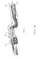
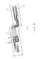
- FIG. 1is a top plan view of a Head Gimbal Assembly having a shunt and an anti-static coating for neutralizing electrostatic charge accumulation;
- FIGS. 2A-Dare cross-sectional views of embodiments of a Head Gimbal Assembly in accordance with the invention.
- FIGS. 3A-Care magnified views of the distal portion of a Head Gimbal Assembly in accordance with the invention.
- FIG. 4is a cross-sectional view of a switched shunt used in the Head Gimbal Assembly in accordance with the invention.
- a Head Gimbal Assembly (HGA) 1for use in a disk drive includes a head 10 having a read element and a write element (not shown), and a Trace Gimbal Assembly (TGA) 2 attached to the head 10 .
- the head 10is mounted on a gimbal 17 as also shown in the magnified view H—H of the area defined by line H—H in FIG. 1, wherein portions of gimbal 17 underneath head 10 appear in phantom.
- the TGA 2includes a conductor array 11 having a first end 13 connected to the head 10 at the read element and the write element and a distal end 15 for connecting the read element and the write element to a signal processing circuit, such as a pre-amplifier circuit (not shown).
- the TGA 2further includes a conductive substrate 14 for supporting the head 10 and the conductor array 11 .
- the conductive substrate 14is a load beam.
- the TGA 2further includes a dielectric layer 16 disposed between the conductor array 11 and the conductive substrate 14 ; and a shunt 18 connected at the distal end 15 for shunting the read element.
- the conductor array 11is a pair of read-paths 12 a connected to the read element for electrically connecting the head to the shunt 18 , and a pair of write-paths 12 b connected to the write element.
- the TGA 2further includes an anti-static coating 19 , covering a substantial portion of the conductor array 11 for neutralizing electrostatic charge accumulation on the conductor array 11 .
- the anti-static coating 19substantially covers at least one of the pairs 12 a and 12 b .
- the anti-static coating 19is a low resistivity dielectric coating characterized by a resistance in the range of 10 kilo-ohms to 100 kilo-ohms.
- FIGS. 2A-Dare cross-sectional views of various embodiments of the present invention taken at line B—B of the HGA 1 of FIG. 1 .
- a dielectric layer 16is disposed between the conductor array 11 (shown by pairs 12 a and 12 b ) and the conductive substrate 14 .
- the dielectric layer 16is of a polyimide composition characterized by a thickness in the range of 10-18 microns.
- the conductive substrateis stainless steel.
- the conductor array 11is disposed on the dielectric layer 16 in the form of a pair of read-paths 12 a and a pair of write-paths 12 b .
- each pair of read-paths 12 a and write-paths 12 bis characterized by a thickness of 10-25 microns.
- a protective layer 20is then disposed atop the conductor array 11 and covering at least one of the pairs 12 a and 12 b . In the embodiment shown in FIG. 2A, the protective layer 20 covers both of the pairs 12 a and 12 b .
- the protective layer 20is of a polyimide composition characterized by a thickness in the range of 15-40 microns.
- the anti-static coating 19is then disposed atop the protective layer 20 so to cover at least one of the pairs 12 a and 12 b , such as covering the pair of read-paths 12 a as shown in FIG.
- the anti-static coating 19is of a polymer composition, such as ST-PolyTM manufactured by Central Corporation or AS-21 developed by Hutchinson Technologies.
- the anti-static coating 19is characterized by a thickness of in the range 10-100 nanometers.
- FIG. 2Bis a cross-sectional view of another embodiment of the HGA 1 of the present invention taken at line B—B of FIG. 1 .
- a conductive backing layer 22is disposed between the conductive substrate 14 and the dielectric layer 16 .
- the conductive backing layeris stainless steel characterized by a thickness of 20 microns.
- the conductive backing layeris copper a composition, such as a copper alloy, characterized by a thickness of 5 microns.
- the conductive backing layer 22extends outside of the area covered by the conductive substrate 14 and all the way to the distal end 15 of the HGA 1 .
- the conductive backing layer 22is disposed based on a predetermined pattern, such as a predetermined windowing pattern, such as in the form of conductive backing layers 22 and window 23 shown in FIG. 2 C.
- a predetermined patternsuch as a predetermined windowing pattern, such as in the form of conductive backing layers 22 and window 23 shown in FIG. 2 C.
- the determination of the patterning featuresis based on impedance and time delay considerations in optimizing the conductor array 11 .
- FIG. 2Dis a cross-sectional view of another embodiment of the HGA 1 of the present invention taken at line B—B of FIG. 1 .
- the anti-static coating 19is disposed adjacent to at least one of the pairs 12 a and 12 b of the conductor array 11 , and used in lieu of the protective layer 20 employed in the preferred embodiments shown in FIGS. 2A-C.
- the anti-static coating 19is characterized by a thickness in the range of 15-40 microns.
- a dielectric layer 16is disposed between the conductor array 11 and the conductive substrate 14 . It should be noted that the patterned conductive backing layer 22 described in conjunction with the preferred embodiments of FIGS. 2B-C can also be readily used in conjunction with the preferred embodiment of FIG. 2 D.
- the dielectric layer 16 in the HGA 1may have (1) a conductive backing layer 22 used in an overall configuration such as those of a Trace Suspension Assembly or a grounded Flex Suspension Assembly; or 2) no conductive backing layer 22 used in an overall configuration such as those used in an ungrounded Flex Suspension Assembly.
- FIGS. 3A-Care magnified views of the distal segment of the various embodiments of HGA 1 as defined by line A—A in FIG. 1 .
- the shunt 18is connected to the distal end 15 via a shunt removal region 30 for removing the shunt, such as by shearing, during a subsequent integration of the HGA 1 into a Head Stack Assembly (not shown).
- the shuntis a switched shunt that can be set to an open position for allowing the electrical testing of the TGA 2 and HGA 1 at various stages of the manufacturing prior to the integration of the HGA 1 into the Head Stack Assembly.
- FIG. 3 A and FIG. 3Bare associated with the preferred embodiments of the present invention shown in FIGS. 2A-C in which the anti-static coating 19 is disposed atop the protective layer 20 .
- the anti-static coating 19is electrically connected to the shunt 18 .
- the anti-static coating 19substantially covers the shunt 18 , ranging from a partial coverage of the shunt 18 , such as covering those portions of the HGA 1 defined by the C—C line shown in FIG. 3A, to a full coverage of the shunt 18 , such as covering those portions of the HGA 1 defined by the D—D line shown in FIG. 3 B.
- FIG. 3Cis associated with the preferred embodiments of the present invention described in conjunction with FIG. 2D in which the anti-static coating 19 is disposed adjacent to the conductor array 11 , and used in lieu of the protective layer 20 employed in the preferred embodiments shown in FIGS. 2A-C.
- the anti-static coating 19may be electrically unconnected to the shunt 18 .
- the anti-static coating 19 coverage of only portions of the HGA 1 such as those substantially defined by the E—E line shown in FIG. 3Cwill suffice for affording protection against ESD and EOS events in accordance with the present invention.
- FIG. 4is a cross-sectional view of a switched shunt 18 used in the HGA 1 of the present invention and taken at line F—F of FIG. 3B, in which the shunt is covered by the anti-static coating 19 .
- a de-shunt pin 40is inserted into the switched shunt 18 to set the switched shunt into an open position. Setting the shunt 18 to an open position, combined with the finite non-zero resistance characteristics of the anti-static coating 19 makes it possible for conducting of electrical testing, such as a Dynamic Electrical Testing (DET), of the TGA 2 and HGA 1 at various stages of the manufacturing prior to the integration of the HGA 1 into the Head Stack Assembly.
- EDTDynamic Electrical Testing
- the anti-static coating 19may be advantageously applied to only predetermined portions of the conductor array 11 based on a predetermined coverage pattern.
- the coverage patternis based on one or more considerations such as the overall mass, material thickness and the ease of manufacturability of the anti-static coating 19 as affecting the mechanical performance of the HGA 1 during the operation of the disk drive.
- One advantage of the foregoing features of the present invention over the prior artis that by using a shunt 18 in conjunction with the anti-static coating 19 in the manners described above, the range of effectives of the shunt 18 is virtually extended over substantially the entire span of the HGA 1 and therefore the HGA 1 is effectively protected from the unbalanced accumulation of the electrostatic charge leading to ESD or EOS events throughout the entire Head Stack Assembly manufacturing process.
Landscapes
- Engineering & Computer Science (AREA)
- Microelectronics & Electronic Packaging (AREA)
- Supporting Of Heads In Record-Carrier Devices (AREA)
- Adjustment Of The Magnetic Head Position Track Following On Tapes (AREA)
Abstract
Description
Claims (33)
Priority Applications (1)
| Application Number | Priority Date | Filing Date | Title |
|---|---|---|---|
| US10/286,170US6801402B1 (en) | 2002-10-31 | 2002-10-31 | ESD-protected head gimbal assembly for use in a disk drive |
Applications Claiming Priority (1)
| Application Number | Priority Date | Filing Date | Title |
|---|---|---|---|
| US10/286,170US6801402B1 (en) | 2002-10-31 | 2002-10-31 | ESD-protected head gimbal assembly for use in a disk drive |
Publications (1)
| Publication Number | Publication Date |
|---|---|
| US6801402B1true US6801402B1 (en) | 2004-10-05 |
Family
ID=33029574
Family Applications (1)
| Application Number | Title | Priority Date | Filing Date |
|---|---|---|---|
| US10/286,170Expired - LifetimeUS6801402B1 (en) | 2002-10-31 | 2002-10-31 | ESD-protected head gimbal assembly for use in a disk drive |
Country Status (1)
| Country | Link |
|---|---|
| US (1) | US6801402B1 (en) |
Cited By (82)
| Publication number | Priority date | Publication date | Assignee | Title |
|---|---|---|---|---|
| US20050052784A1 (en)* | 2003-09-05 | 2005-03-10 | Hitachi Global Storage Technologies Netherlands, B.V. | Suspension assembly and magnetic disk drive |
| US6870706B1 (en)* | 2002-08-07 | 2005-03-22 | Headway Technologies, Inc. | Method for suppressing tribocharge in the assembly of magnetic heads |
| US20050117257A1 (en)* | 2003-12-01 | 2005-06-02 | Kr Precision Public Company Limited | Method to form electrostatic discharge protection on flexible circuits |
| US6995954B1 (en)* | 2001-07-13 | 2006-02-07 | Magnecomp Corporation | ESD protected suspension interconnect |
| US20060152854A1 (en)* | 2005-01-13 | 2006-07-13 | Arya Satya P | Method and apparatus for reducing crosstalk and signal loss in flexing interconnects of an electrical lead suspension |
| US20060190673A1 (en)* | 2005-02-21 | 2006-08-24 | Nhk Spring Co., Ltd. | Head suspension |
| US20060187587A1 (en)* | 2005-02-21 | 2006-08-24 | Hajime Arai | Head suspension |
| US20060269730A1 (en)* | 2005-05-30 | 2006-11-30 | Nitto Denko Corporation | Wired circuit board and production method thereof |
| US20060285253A1 (en)* | 2005-06-15 | 2006-12-21 | Seagate Technology Llc | Unified suspension laminate |
| US20060292738A1 (en)* | 2005-06-28 | 2006-12-28 | Seagate Technology Llc | Flex on suspension with a heat-conducting protective layer for reflowing solder interconnects |
| US20070131449A1 (en)* | 2005-12-08 | 2007-06-14 | Nitto Denko Corporation | Wired circuit board and producing method thereof |
| US20070235219A1 (en)* | 2006-04-05 | 2007-10-11 | Nitto Denko Corporation | Wired circuit board and production method thereof |
| EP1865759A2 (en) | 2006-05-01 | 2007-12-12 | Nitto Denko Corporation | Wired circuit board |
| EP1871152A1 (en)* | 2006-06-22 | 2007-12-26 | Nitto Denko Corporation | Wired circuit board |
| EP1874100A1 (en)* | 2006-06-29 | 2008-01-02 | Nitto Denko Corporation | Wired circuit board |
| US20080055788A1 (en)* | 2006-08-31 | 2008-03-06 | Fujitsu Limited | Perpendicularly feeding type magnetic head having adjustable input impedance, manufacturing method thereof, head suspension assembly, and magnetic storage device |
| US20080062567A1 (en)* | 2006-09-13 | 2008-03-13 | Nhk Spring Co., Ltd. | Suspension device |
| US20080253028A1 (en)* | 2007-04-16 | 2008-10-16 | Jen-Yuan Chang | System and apparatus for vibration damping of integrated lead suspensions in high density magnetic storage devices |
| US20080273269A1 (en)* | 2007-05-04 | 2008-11-06 | Hutchinson Technology Incorporated | Disk drive head suspension flexures having alternating width stacked leads |
| US20080277147A1 (en)* | 2007-05-11 | 2008-11-13 | Nitto Denko Corporation | Wired circuit board and producing method thereof |
| US20090025217A1 (en)* | 2007-07-24 | 2009-01-29 | Nitto Denko Corporation | Producing method of wired circuit board |
| EP1843648A3 (en)* | 2006-04-05 | 2009-05-06 | Nitto Denko Corporation | Wired circuit board and production method thereof |
| US20110090602A1 (en)* | 2008-09-22 | 2011-04-21 | Nobumasa Nishiyama | Head-gimbal assembly including a transmission-line structure for high-density magnetic recording |
| US20110149442A1 (en)* | 2009-12-22 | 2011-06-23 | Contreras John T | Conductor suspension structure for hard disk drives |
| CN102177627A (en)* | 2008-10-10 | 2011-09-07 | 昭和电工株式会社 | Electrostatic discharge protector |
| US20120002320A1 (en)* | 2010-06-30 | 2012-01-05 | Charles Allan Brown | Particle-capturing device including a component configured to provide an additional function within an enclosure exclusive of capturing particles |
| US8169746B1 (en) | 2008-04-08 | 2012-05-01 | Hutchinson Technology Incorporated | Integrated lead suspension with multiple trace configurations |
| US8598460B2 (en) | 2010-12-22 | 2013-12-03 | HGST Netherlands B.V. | Interleaved conductor structure with offset traces |
| US8675311B2 (en) | 2010-12-22 | 2014-03-18 | HGST Netherlands B.V. | Interleaved conductor structure with wrap around traces |
| US8675314B1 (en) | 2013-08-21 | 2014-03-18 | Hutchinson Technology Incorporated | Co-located gimbal-based dual stage actuation disk drive suspensions with offset motors |
| US8681456B1 (en) | 2012-09-14 | 2014-03-25 | Hutchinson Technology Incorporated | Co-located gimbal-based dual stage actuation disk drive suspensions |
| US8717712B1 (en) | 2013-07-15 | 2014-05-06 | Hutchinson Technology Incorporated | Disk drive suspension assembly having a partially flangeless load point dimple |
| US8792214B1 (en) | 2013-07-23 | 2014-07-29 | Hutchinson Technology Incorporated | Electrical contacts to motors in dual stage actuated suspensions |
| US8861141B2 (en) | 2012-08-31 | 2014-10-14 | Hutchinson Technology Incorporated | Damped dual stage actuation disk drive suspensions |
| US8891206B2 (en) | 2012-12-17 | 2014-11-18 | Hutchinson Technology Incorporated | Co-located gimbal-based dual stage actuation disk drive suspensions with motor stiffener |
| US8896969B1 (en) | 2013-05-23 | 2014-11-25 | Hutchinson Technology Incorporated | Two-motor co-located gimbal-based dual stage actuation disk drive suspensions with motor stiffeners |
| US8896968B2 (en) | 2012-10-10 | 2014-11-25 | Hutchinson Technology Incorporated | Co-located gimbal-based dual stage actuation disk drive suspensions with dampers |
| US8896970B1 (en) | 2013-12-31 | 2014-11-25 | Hutchinson Technology Incorporated | Balanced co-located gimbal-based dual stage actuation disk drive suspensions |
| US8929180B1 (en) | 2013-04-25 | 2015-01-06 | Western Digital Technologies, Inc. | Energy-assisted magnetic recording device having laser driving signal and magnetic write signal sharing same electrical conductor |
| US8934199B1 (en) | 2014-03-31 | 2015-01-13 | Western Digital Technologies, Inc. | Disk drive head suspension tail with bond pad edge alignment features |
| US8941951B2 (en) | 2012-11-28 | 2015-01-27 | Hutchinson Technology Incorporated | Head suspension flexure with integrated strain sensor and sputtered traces |
| US8976491B1 (en) | 2013-05-09 | 2015-03-10 | Western Digital Technologies, Inc. | Disk drive head suspension distal non-op shock limiter with branched arms |
| US8988830B1 (en) | 2013-05-13 | 2015-03-24 | Western Digital (Fremont), Llc | Air bearing design to mitigate lube waterfall effect |
| US9001469B2 (en) | 2012-03-16 | 2015-04-07 | Hutchinson Technology Incorporated | Mid-loadbeam dual stage actuated (DSA) disk drive head suspension |
| US9042048B1 (en) | 2014-09-30 | 2015-05-26 | Western Digital (Fremont), Llc | Laser-ignited reactive HAMR bonding |
| US9064513B1 (en) | 2014-03-07 | 2015-06-23 | Western Digital Technologies, Inc. | Disk drive suspension assembly with flexure having dual conductive layers with staggered traces |
| US9070387B1 (en) | 2013-08-23 | 2015-06-30 | Western Digital Technologies, Inc. | Integrated heat-assisted magnetic recording head/laser assembly |
| US9093102B1 (en) | 2013-03-12 | 2015-07-28 | Western Digital Technologies, Inc. | Systems and methods for tuning seed layer hardness in components of magnetic recording systems |
| US9099145B1 (en) | 2013-12-24 | 2015-08-04 | Western Digital (Fremont), Llc | High contrast alignment marker |
| US9105282B1 (en) | 2013-05-20 | 2015-08-11 | Western Digital Technologies, Inc. | Head gimbal assembly carrier with adjustable protective bar |
| US9117467B1 (en) | 2014-08-19 | 2015-08-25 | Sae Magnetics (H.K.) Ltd. | Disk drive head suspension including a grounded conductive substrate |
| US9135935B1 (en) | 2013-10-11 | 2015-09-15 | Western Digital Technologies, Inc. | Customized head gimbal assembly bonding skew angle for adjusting two-dimensional magnetic recording reader alignment |
| US9165579B1 (en) | 2014-09-26 | 2015-10-20 | Western Digital (Fremont), Llc | Air bearing area configuration for reducing flying height hump across a stroke |
| US9171562B1 (en) | 2015-03-19 | 2015-10-27 | Western Digital (Fremont), Llc | Patterned metal layer to control solder connection between laser and submount in a magnetic head |
| US9183859B1 (en) | 2014-11-11 | 2015-11-10 | Western Digital (Fremont), Llc | HAMR writer pole length characterization |
| US9190090B1 (en) | 2014-12-24 | 2015-11-17 | Western Digital (Fremont), Llc | Multi step lube blocking air bearing area configuration |
| US9190089B1 (en) | 2014-12-24 | 2015-11-17 | Western Digital (Fremont), Llc | Air bearing area configuration for contaminating particle removal |
| US9202478B1 (en) | 2015-02-10 | 2015-12-01 | Western Digital (Fremont), Llc | Method and structure for soldering a laser submount to a mounting face of a slider |
| US9230580B1 (en) | 2010-06-30 | 2016-01-05 | Western Digital Technologies, Inc. | Suspension assembly having a microactuator grounded to a flexure |
| US9245555B2 (en) | 2010-05-24 | 2016-01-26 | Hutchinson Technology Incorporated | Low resistance ground joints for dual stage actuation disk drive suspensions |
| US9242340B1 (en) | 2013-03-12 | 2016-01-26 | Western Digital Technologies, Inc. | Method to stress relieve a magnetic recording head transducer utilizing ultrasonic cavitation |
| US9257138B1 (en) | 2014-10-28 | 2016-02-09 | Western Digital (Fremont), Llc | Slider assembly and method of manufacturing same |
| US9293157B1 (en) | 2012-06-28 | 2016-03-22 | Western Digital Technologies, Inc. | Automated active feedback slice and view milling of magnetic head cross-sections |
| US9315008B1 (en) | 2013-07-16 | 2016-04-19 | Western Digital Technologies, Inc. | Method and apparatus for aligning an illumination unit to a slider for a magnetic recording device |
| US9343084B2 (en) | 2012-03-14 | 2016-05-17 | Western Digital Technologies, Inc. | Systems and methods for correcting slider parallelism error using compensation lapping |
| US9361916B1 (en) | 2014-03-13 | 2016-06-07 | Western Digital (Fremont) | Electrical lapping guide for dimensional control of back side of heat assisted magnetic recording device |
| US9368139B1 (en) | 2015-03-20 | 2016-06-14 | Western Digital (Fremont), Llc | Slider back side etching to increase shear strength between suspension and slider |
| US9372078B1 (en) | 2014-06-20 | 2016-06-21 | Western Digital (Fremont), Llc | Detecting thickness variation and quantitative depth utilizing scanning electron microscopy with a surface profiler |
| US9387568B1 (en) | 2013-02-27 | 2016-07-12 | Western Digital Technologies, Inc. | Systems and methods for correcting fabrication error in magnetic recording heads using magnetic write width measurements |
| US9431042B2 (en) | 2014-01-03 | 2016-08-30 | Hutchinson Technology Incorporated | Balanced multi-trace transmission in a hard disk drive flexure |
| US9431044B1 (en) | 2014-05-07 | 2016-08-30 | Western Digital (Fremont), Llc | Slider having shock and particle resistance |
| US9431037B2 (en) | 2013-03-12 | 2016-08-30 | Western Digitatl (Fremont), LLC | Systems and methods for monitoring the power of a light source utilized in energy-assisted magnetic recording |
| US9558771B2 (en) | 2014-12-16 | 2017-01-31 | Hutchinson Technology Incorporated | Piezoelectric disk drive suspension motors having plated stiffeners |
| US9564154B2 (en) | 2014-12-22 | 2017-02-07 | Hutchinson Technology Incorporated | Multilayer disk drive motors having out-of-plane bending |
| US9646638B1 (en) | 2016-05-12 | 2017-05-09 | Hutchinson Technology Incorporated | Co-located gimbal-based DSA disk drive suspension with traces routed around slider pad |
| US9659587B1 (en) | 2015-11-06 | 2017-05-23 | Western Digital (Fremont), Llc | Magnetic head having a reader overcoat with DLC and a recessed writer overcoat without DLC |
| US9659589B2 (en) | 2015-09-29 | 2017-05-23 | Western Digital (Fremont), Llc | Free-standing reflector usable in heat assisted magnetic recording technology |
| US9685187B1 (en) | 2014-09-26 | 2017-06-20 | Western Digital (Fremont), Llc | Bonding tool and method for high accuracy chip-to-chip bonding |
| US9734852B2 (en) | 2015-06-30 | 2017-08-15 | Hutchinson Technology Incorporated | Disk drive head suspension structures having improved gold-dielectric joint reliability |
| US9805748B1 (en) | 2014-06-24 | 2017-10-31 | Western Digital (Fremont), Llc | System and method for providing a protective layer having a graded intermediate layer |
| US9824704B2 (en) | 2015-02-17 | 2017-11-21 | Hutchinson Technology Incorporated | Partial curing of a microactuator mounting adhesive in a disk drive suspension |
| US9870788B2 (en) | 2014-01-08 | 2018-01-16 | Western Digital (Fremont), Llc | Method of adjusting tilt using magnetic erase width feedback |
Citations (6)
| Publication number | Priority date | Publication date | Assignee | Title |
|---|---|---|---|---|
| US5680274A (en)* | 1994-06-27 | 1997-10-21 | International Business Machines Corporation | Integrated suspension for an information storage system having electrostatic discharge protection |
| US6075676A (en)* | 1998-04-28 | 2000-06-13 | Fujitsu Limited | Head assembly including shorted head leads for preventing damage of head during manufacture of a magnetic storage system |
| US6125015A (en)* | 1998-12-04 | 2000-09-26 | Read-Rite Corporation | Head gimbal assembly with low stiffness flex circuit and ESD Protection |
| US6163443A (en)* | 1998-02-19 | 2000-12-19 | Fujitsu Limited | Actuator having MR element protecting means |
| US6459043B1 (en)* | 2001-03-29 | 2002-10-01 | 3M Innovative Properties Company | Flexible circuit with electrostatic damage limiting feature and method of manufacture |
| US20020154454A1 (en)* | 2001-03-09 | 2002-10-24 | Kupinski Paul E. | Bleed resistor for minimizing ESD damage |
- 2002
- 2002-10-31USUS10/286,170patent/US6801402B1/ennot_activeExpired - Lifetime
Patent Citations (6)
| Publication number | Priority date | Publication date | Assignee | Title |
|---|---|---|---|---|
| US5680274A (en)* | 1994-06-27 | 1997-10-21 | International Business Machines Corporation | Integrated suspension for an information storage system having electrostatic discharge protection |
| US6163443A (en)* | 1998-02-19 | 2000-12-19 | Fujitsu Limited | Actuator having MR element protecting means |
| US6075676A (en)* | 1998-04-28 | 2000-06-13 | Fujitsu Limited | Head assembly including shorted head leads for preventing damage of head during manufacture of a magnetic storage system |
| US6125015A (en)* | 1998-12-04 | 2000-09-26 | Read-Rite Corporation | Head gimbal assembly with low stiffness flex circuit and ESD Protection |
| US20020154454A1 (en)* | 2001-03-09 | 2002-10-24 | Kupinski Paul E. | Bleed resistor for minimizing ESD damage |
| US6459043B1 (en)* | 2001-03-29 | 2002-10-01 | 3M Innovative Properties Company | Flexible circuit with electrostatic damage limiting feature and method of manufacture |
Non-Patent Citations (3)
| Title |
|---|
| "TSA Suspension Application Guide" From Hutchinson Technology Inc. Published Sep. 18, 1998, Updated Sep. 10, 1999, Sep. 8, 2000 and Sep. 7, 2001. |
| Anti-Static Coating (AS-21), Preliminary Data Sheet; pp. 1-4; Hutchinson Technology, Sep. 9, 2002 (draft copy). |
| Brian Thornton & Mark Tanaka, Read-Rite Corp.; "FSA vs TSA", Insight Magazine Article pp. 28-30;, Spring 2002. |
Cited By (137)
| Publication number | Priority date | Publication date | Assignee | Title |
|---|---|---|---|---|
| US6995954B1 (en)* | 2001-07-13 | 2006-02-07 | Magnecomp Corporation | ESD protected suspension interconnect |
| US6870706B1 (en)* | 2002-08-07 | 2005-03-22 | Headway Technologies, Inc. | Method for suppressing tribocharge in the assembly of magnetic heads |
| US20050168878A1 (en)* | 2002-08-07 | 2005-08-04 | Headway Technologies, Inc. | Method for suppressing tribocharge in the assembly of magnetic heads |
| US6995958B2 (en)* | 2002-08-07 | 2006-02-07 | Headway Technologies, Inc. | Method for suppressing tribocharge in the assembly of magnetic heads |
| US20050052784A1 (en)* | 2003-09-05 | 2005-03-10 | Hitachi Global Storage Technologies Netherlands, B.V. | Suspension assembly and magnetic disk drive |
| US20050117257A1 (en)* | 2003-12-01 | 2005-06-02 | Kr Precision Public Company Limited | Method to form electrostatic discharge protection on flexible circuits |
| US7489493B2 (en) | 2003-12-01 | 2009-02-10 | Magnecomp Corporation | Method to form electrostatic discharge protection on flexible circuits using a diamond-like carbon material |
| US20060152854A1 (en)* | 2005-01-13 | 2006-07-13 | Arya Satya P | Method and apparatus for reducing crosstalk and signal loss in flexing interconnects of an electrical lead suspension |
| US7352535B2 (en)* | 2005-01-13 | 2008-04-01 | Hitachi Global Storage Technologies Netherlands, B.V. | Method and apparatus for reducing crosstalk and signal loss in flexing interconnects of an electrical lead suspension |
| US20060190673A1 (en)* | 2005-02-21 | 2006-08-24 | Nhk Spring Co., Ltd. | Head suspension |
| US7643252B2 (en) | 2005-02-21 | 2010-01-05 | Nhk Spring Co., Ltd. | Head suspension having wiring disposed with conductive layer |
| CN1825434B (en)* | 2005-02-21 | 2011-01-12 | 日本发条株式会社 | head suspension |
| US20060187587A1 (en)* | 2005-02-21 | 2006-08-24 | Hajime Arai | Head suspension |
| US7692899B2 (en)* | 2005-02-21 | 2010-04-06 | Nhk Spring Co., Ltd. | Head suspension having wiring disposed in contact with slightly conductive flexible resin |
| CN1825433B (en)* | 2005-02-21 | 2010-07-14 | 日本发条株式会社 | head suspension |
| US7566833B2 (en)* | 2005-05-30 | 2009-07-28 | Nitto Denko Corporation | Wired circuit board and production method thereof |
| CN1874651B (en)* | 2005-05-30 | 2010-04-14 | 日东电工株式会社 | Wiring circuit board and manufacturing method thereof |
| US20060269730A1 (en)* | 2005-05-30 | 2006-11-30 | Nitto Denko Corporation | Wired circuit board and production method thereof |
| US7466517B2 (en) | 2005-06-15 | 2008-12-16 | Seagate Technology Llc | Unified suspension laminate |
| US20060285253A1 (en)* | 2005-06-15 | 2006-12-21 | Seagate Technology Llc | Unified suspension laminate |
| US20060292738A1 (en)* | 2005-06-28 | 2006-12-28 | Seagate Technology Llc | Flex on suspension with a heat-conducting protective layer for reflowing solder interconnects |
| US7646567B2 (en) | 2005-06-28 | 2010-01-12 | Seagate Technology Llc | Flex on suspension with a heat-conducting protective layer for reflowing solder interconnects |
| US20070131449A1 (en)* | 2005-12-08 | 2007-06-14 | Nitto Denko Corporation | Wired circuit board and producing method thereof |
| US20090142478A1 (en)* | 2005-12-08 | 2009-06-04 | Nitto Denko Corporation | Wired circuit board and producing method thereof |
| US7501581B2 (en)* | 2005-12-08 | 2009-03-10 | Nitto Denko Corporation | Wired circuit board and producing method thereof |
| EP1843648A3 (en)* | 2006-04-05 | 2009-05-06 | Nitto Denko Corporation | Wired circuit board and production method thereof |
| US20070235219A1 (en)* | 2006-04-05 | 2007-10-11 | Nitto Denko Corporation | Wired circuit board and production method thereof |
| US7782571B2 (en)* | 2006-04-05 | 2010-08-24 | Nitto Denko Corporation | Wired circuit board and production method thereof |
| CN101052269B (en)* | 2006-04-05 | 2010-07-21 | 日东电工株式会社 | Wiring circuit board and manufacturing method thereof |
| EP1865759A3 (en)* | 2006-05-01 | 2009-05-06 | Nitto Denko Corporation | Wired circuit board |
| EP1865759A2 (en) | 2006-05-01 | 2007-12-12 | Nitto Denko Corporation | Wired circuit board |
| CN101068451B (en)* | 2006-05-01 | 2011-03-23 | 日东电工株式会社 | Wired circuit board |
| EP1871152A1 (en)* | 2006-06-22 | 2007-12-26 | Nitto Denko Corporation | Wired circuit board |
| US20090183907A1 (en)* | 2006-06-22 | 2009-07-23 | Nitto Denko Corporation | Wired circuit board |
| US8247700B2 (en)* | 2006-06-22 | 2012-08-21 | Nitto Denko Corporation | Wired circuit board |
| US20070295534A1 (en)* | 2006-06-22 | 2007-12-27 | Nitto Denko Corporation | Wired circuit board |
| EP2040519A3 (en)* | 2006-06-22 | 2009-05-06 | Nitto Denko Corporation | Wired Circuit Board |
| US7737365B2 (en)* | 2006-06-22 | 2010-06-15 | Nitto Denko Corporation | Wired circuit board |
| CN101557678B (en)* | 2006-06-22 | 2011-04-13 | 日东电工株式会社 | Wired circuit board |
| US7629539B2 (en)* | 2006-06-29 | 2009-12-08 | Nitto Denko Corporation | Wired circuit board |
| US20080000673A1 (en)* | 2006-06-29 | 2008-01-03 | Nitto Denko Corporation | Wired circuit board |
| EP1874100A1 (en)* | 2006-06-29 | 2008-01-02 | Nitto Denko Corporation | Wired circuit board |
| CN101098586B (en)* | 2006-06-29 | 2010-07-21 | 日东电工株式会社 | Wiring circuit board |
| US20080055788A1 (en)* | 2006-08-31 | 2008-03-06 | Fujitsu Limited | Perpendicularly feeding type magnetic head having adjustable input impedance, manufacturing method thereof, head suspension assembly, and magnetic storage device |
| US8014107B2 (en)* | 2006-09-13 | 2011-09-06 | Nhk Spring Co., Ltd. | Suspension device |
| US20080062567A1 (en)* | 2006-09-13 | 2008-03-13 | Nhk Spring Co., Ltd. | Suspension device |
| US20080253028A1 (en)* | 2007-04-16 | 2008-10-16 | Jen-Yuan Chang | System and apparatus for vibration damping of integrated lead suspensions in high density magnetic storage devices |
| US7903376B2 (en) | 2007-04-16 | 2011-03-08 | Hitachi Global Storage Technologies Netherlands, B.V. | Integrated lead suspension for vibration damping in magnetic storage device |
| US7782572B2 (en)* | 2007-05-04 | 2010-08-24 | Hutchinson Technology Incorporated | Disk drive head suspension flexures having alternating width stacked leads |
| US20080273269A1 (en)* | 2007-05-04 | 2008-11-06 | Hutchinson Technology Incorporated | Disk drive head suspension flexures having alternating width stacked leads |
| US7982136B2 (en)* | 2007-05-11 | 2011-07-19 | Nitto Denko Corporation | Wired circuit board and producing method thereof |
| US20080277147A1 (en)* | 2007-05-11 | 2008-11-13 | Nitto Denko Corporation | Wired circuit board and producing method thereof |
| US7895741B2 (en)* | 2007-07-24 | 2011-03-01 | Nitto Denko Corporation | Method of producing a wired circuit board |
| US20090025217A1 (en)* | 2007-07-24 | 2009-01-29 | Nitto Denko Corporation | Producing method of wired circuit board |
| US8169746B1 (en) | 2008-04-08 | 2012-05-01 | Hutchinson Technology Incorporated | Integrated lead suspension with multiple trace configurations |
| US20110090602A1 (en)* | 2008-09-22 | 2011-04-21 | Nobumasa Nishiyama | Head-gimbal assembly including a transmission-line structure for high-density magnetic recording |
| US8248732B2 (en)* | 2008-09-22 | 2012-08-21 | Hitachi Global Storage Technologies, Netherlands B.V. | Head-gimbal assembly including a transmission-line structure for high-density magnetic recording |
| CN102177627A (en)* | 2008-10-10 | 2011-09-07 | 昭和电工株式会社 | Electrostatic discharge protector |
| US8310789B2 (en) | 2009-12-22 | 2012-11-13 | Hitachi Global Storage Technologies Netherlands B.V. | Conductor suspension structure and electrical connection assembly for transmitting complementary signals in a hard disk drive |
| US20110149442A1 (en)* | 2009-12-22 | 2011-06-23 | Contreras John T | Conductor suspension structure for hard disk drives |
| US9245555B2 (en) | 2010-05-24 | 2016-01-26 | Hutchinson Technology Incorporated | Low resistance ground joints for dual stage actuation disk drive suspensions |
| US9812160B2 (en) | 2010-05-24 | 2017-11-07 | Hutchinson Technology Incorporated | Low resistance ground joints for dual stage actuation disk drive suspensions |
| US8427775B2 (en)* | 2010-06-30 | 2013-04-23 | HGST Netherlands B.V. | Particle-capturing device including a component configured to provide an additional function within an enclosure exclusive of capturing particles |
| US20120002320A1 (en)* | 2010-06-30 | 2012-01-05 | Charles Allan Brown | Particle-capturing device including a component configured to provide an additional function within an enclosure exclusive of capturing particles |
| US9230580B1 (en) | 2010-06-30 | 2016-01-05 | Western Digital Technologies, Inc. | Suspension assembly having a microactuator grounded to a flexure |
| US8598460B2 (en) | 2010-12-22 | 2013-12-03 | HGST Netherlands B.V. | Interleaved conductor structure with offset traces |
| US8675311B2 (en) | 2010-12-22 | 2014-03-18 | HGST Netherlands B.V. | Interleaved conductor structure with wrap around traces |
| US9343084B2 (en) | 2012-03-14 | 2016-05-17 | Western Digital Technologies, Inc. | Systems and methods for correcting slider parallelism error using compensation lapping |
| US9001469B2 (en) | 2012-03-16 | 2015-04-07 | Hutchinson Technology Incorporated | Mid-loadbeam dual stage actuated (DSA) disk drive head suspension |
| US9293157B1 (en) | 2012-06-28 | 2016-03-22 | Western Digital Technologies, Inc. | Automated active feedback slice and view milling of magnetic head cross-sections |
| US8861141B2 (en) | 2012-08-31 | 2014-10-14 | Hutchinson Technology Incorporated | Damped dual stage actuation disk drive suspensions |
| US9001471B2 (en) | 2012-09-14 | 2015-04-07 | Hutchinson Technology Incorporated | Co-located gimbal-based dual stage actuation disk drive suspensions |
| US8681456B1 (en) | 2012-09-14 | 2014-03-25 | Hutchinson Technology Incorporated | Co-located gimbal-based dual stage actuation disk drive suspensions |
| US8896968B2 (en) | 2012-10-10 | 2014-11-25 | Hutchinson Technology Incorporated | Co-located gimbal-based dual stage actuation disk drive suspensions with dampers |
| US9240203B2 (en) | 2012-10-10 | 2016-01-19 | Hutchinson Technology Incorporated | Co-located gimbal-based dual stage actuation disk drive suspensions with dampers |
| US8941951B2 (en) | 2012-11-28 | 2015-01-27 | Hutchinson Technology Incorporated | Head suspension flexure with integrated strain sensor and sputtered traces |
| US8891206B2 (en) | 2012-12-17 | 2014-11-18 | Hutchinson Technology Incorporated | Co-located gimbal-based dual stage actuation disk drive suspensions with motor stiffener |
| US9257139B2 (en) | 2012-12-17 | 2016-02-09 | Hutchinson Technology Incorporated | Co-located gimbal-based dual stage actuation disk drive suspensions with motor stiffeners |
| US9387568B1 (en) | 2013-02-27 | 2016-07-12 | Western Digital Technologies, Inc. | Systems and methods for correcting fabrication error in magnetic recording heads using magnetic write width measurements |
| US9449631B2 (en) | 2013-03-12 | 2016-09-20 | Western Digital Technologies, Inc. | Slider for magnetic recording system |
| US9431037B2 (en) | 2013-03-12 | 2016-08-30 | Western Digitatl (Fremont), LLC | Systems and methods for monitoring the power of a light source utilized in energy-assisted magnetic recording |
| US9093102B1 (en) | 2013-03-12 | 2015-07-28 | Western Digital Technologies, Inc. | Systems and methods for tuning seed layer hardness in components of magnetic recording systems |
| US9242340B1 (en) | 2013-03-12 | 2016-01-26 | Western Digital Technologies, Inc. | Method to stress relieve a magnetic recording head transducer utilizing ultrasonic cavitation |
| US8929180B1 (en) | 2013-04-25 | 2015-01-06 | Western Digital Technologies, Inc. | Energy-assisted magnetic recording device having laser driving signal and magnetic write signal sharing same electrical conductor |
| US8976491B1 (en) | 2013-05-09 | 2015-03-10 | Western Digital Technologies, Inc. | Disk drive head suspension distal non-op shock limiter with branched arms |
| US8988830B1 (en) | 2013-05-13 | 2015-03-24 | Western Digital (Fremont), Llc | Air bearing design to mitigate lube waterfall effect |
| US9105282B1 (en) | 2013-05-20 | 2015-08-11 | Western Digital Technologies, Inc. | Head gimbal assembly carrier with adjustable protective bar |
| US10629232B2 (en) | 2013-05-23 | 2020-04-21 | Hutchinson Technology Incorporated | Two-motor co-located gimbal-based dual stage actuation disk drive suspensions with motor stiffeners |
| US9613644B2 (en) | 2013-05-23 | 2017-04-04 | Hutchinson Technology Incorporated | Two-motor co-located gimbal-based dual stage actuation disk drive suspensions with motor stiffeners |
| US8896969B1 (en) | 2013-05-23 | 2014-11-25 | Hutchinson Technology Incorporated | Two-motor co-located gimbal-based dual stage actuation disk drive suspensions with motor stiffeners |
| US9997183B2 (en) | 2013-05-23 | 2018-06-12 | Hutchinson Technology Incorporated | Two-motor co-located gimbal-based dual stage actuation disk drive suspensions with motor stiffeners |
| US10002629B2 (en) | 2013-07-15 | 2018-06-19 | Hutchinson Technology Incorporated | Disk drive suspension assembly having a partially flangeless load point dimple |
| US9524739B2 (en) | 2013-07-15 | 2016-12-20 | Hutchinson Technology Incorporated | Disk drive suspension assembly having a partially flangeless load point dimple |
| US9007726B2 (en) | 2013-07-15 | 2015-04-14 | Hutchinson Technology Incorporated | Disk drive suspension assembly having a partially flangeless load point dimple |
| US9870792B2 (en) | 2013-07-15 | 2018-01-16 | Hutchinson Technology Incorporated | Disk drive suspension assembly having a partially flangeless load point dimple |
| US8717712B1 (en) | 2013-07-15 | 2014-05-06 | Hutchinson Technology Incorporated | Disk drive suspension assembly having a partially flangeless load point dimple |
| US9315008B1 (en) | 2013-07-16 | 2016-04-19 | Western Digital Technologies, Inc. | Method and apparatus for aligning an illumination unit to a slider for a magnetic recording device |
| US8792214B1 (en) | 2013-07-23 | 2014-07-29 | Hutchinson Technology Incorporated | Electrical contacts to motors in dual stage actuated suspensions |
| US8675314B1 (en) | 2013-08-21 | 2014-03-18 | Hutchinson Technology Incorporated | Co-located gimbal-based dual stage actuation disk drive suspensions with offset motors |
| US9070387B1 (en) | 2013-08-23 | 2015-06-30 | Western Digital Technologies, Inc. | Integrated heat-assisted magnetic recording head/laser assembly |
| US9135935B1 (en) | 2013-10-11 | 2015-09-15 | Western Digital Technologies, Inc. | Customized head gimbal assembly bonding skew angle for adjusting two-dimensional magnetic recording reader alignment |
| US9099145B1 (en) | 2013-12-24 | 2015-08-04 | Western Digital (Fremont), Llc | High contrast alignment marker |
| US8896970B1 (en) | 2013-12-31 | 2014-11-25 | Hutchinson Technology Incorporated | Balanced co-located gimbal-based dual stage actuation disk drive suspensions |
| US9147413B2 (en) | 2013-12-31 | 2015-09-29 | Hutchinson Technology Incorporated | Balanced co-located gimbal-based dual stage actuation disk drive suspensions |
| US9431042B2 (en) | 2014-01-03 | 2016-08-30 | Hutchinson Technology Incorporated | Balanced multi-trace transmission in a hard disk drive flexure |
| US9870788B2 (en) | 2014-01-08 | 2018-01-16 | Western Digital (Fremont), Llc | Method of adjusting tilt using magnetic erase width feedback |
| US9064513B1 (en) | 2014-03-07 | 2015-06-23 | Western Digital Technologies, Inc. | Disk drive suspension assembly with flexure having dual conductive layers with staggered traces |
| US9361916B1 (en) | 2014-03-13 | 2016-06-07 | Western Digital (Fremont) | Electrical lapping guide for dimensional control of back side of heat assisted magnetic recording device |
| US8934199B1 (en) | 2014-03-31 | 2015-01-13 | Western Digital Technologies, Inc. | Disk drive head suspension tail with bond pad edge alignment features |
| US9431044B1 (en) | 2014-05-07 | 2016-08-30 | Western Digital (Fremont), Llc | Slider having shock and particle resistance |
| US9372078B1 (en) | 2014-06-20 | 2016-06-21 | Western Digital (Fremont), Llc | Detecting thickness variation and quantitative depth utilizing scanning electron microscopy with a surface profiler |
| US9805748B1 (en) | 2014-06-24 | 2017-10-31 | Western Digital (Fremont), Llc | System and method for providing a protective layer having a graded intermediate layer |
| US9117467B1 (en) | 2014-08-19 | 2015-08-25 | Sae Magnetics (H.K.) Ltd. | Disk drive head suspension including a grounded conductive substrate |
| US9685187B1 (en) | 2014-09-26 | 2017-06-20 | Western Digital (Fremont), Llc | Bonding tool and method for high accuracy chip-to-chip bonding |
| US9165579B1 (en) | 2014-09-26 | 2015-10-20 | Western Digital (Fremont), Llc | Air bearing area configuration for reducing flying height hump across a stroke |
| US9042048B1 (en) | 2014-09-30 | 2015-05-26 | Western Digital (Fremont), Llc | Laser-ignited reactive HAMR bonding |
| US9257138B1 (en) | 2014-10-28 | 2016-02-09 | Western Digital (Fremont), Llc | Slider assembly and method of manufacturing same |
| US9183859B1 (en) | 2014-11-11 | 2015-11-10 | Western Digital (Fremont), Llc | HAMR writer pole length characterization |
| US9715890B2 (en) | 2014-12-16 | 2017-07-25 | Hutchinson Technology Incorporated | Piezoelectric disk drive suspension motors having plated stiffeners |
| US10002628B2 (en) | 2014-12-16 | 2018-06-19 | Hutchinson Technology Incorporated | Piezoelectric motors including a stiffener layer |
| US9558771B2 (en) | 2014-12-16 | 2017-01-31 | Hutchinson Technology Incorporated | Piezoelectric disk drive suspension motors having plated stiffeners |
| US10339966B2 (en) | 2014-12-22 | 2019-07-02 | Hutchinson Technology Incorporated | Multilayer disk drive motors having out-of-plane bending |
| US9564154B2 (en) | 2014-12-22 | 2017-02-07 | Hutchinson Technology Incorporated | Multilayer disk drive motors having out-of-plane bending |
| US9190089B1 (en) | 2014-12-24 | 2015-11-17 | Western Digital (Fremont), Llc | Air bearing area configuration for contaminating particle removal |
| US9190090B1 (en) | 2014-12-24 | 2015-11-17 | Western Digital (Fremont), Llc | Multi step lube blocking air bearing area configuration |
| US9202478B1 (en) | 2015-02-10 | 2015-12-01 | Western Digital (Fremont), Llc | Method and structure for soldering a laser submount to a mounting face of a slider |
| US9824704B2 (en) | 2015-02-17 | 2017-11-21 | Hutchinson Technology Incorporated | Partial curing of a microactuator mounting adhesive in a disk drive suspension |
| US10147449B2 (en) | 2015-02-17 | 2018-12-04 | Hutchinson Technology Incorporated | Partial curing of a microactuator mounting adhesive in a disk drive suspension |
| US9171562B1 (en) | 2015-03-19 | 2015-10-27 | Western Digital (Fremont), Llc | Patterned metal layer to control solder connection between laser and submount in a magnetic head |
| US9368139B1 (en) | 2015-03-20 | 2016-06-14 | Western Digital (Fremont), Llc | Slider back side etching to increase shear strength between suspension and slider |
| US9734852B2 (en) | 2015-06-30 | 2017-08-15 | Hutchinson Technology Incorporated | Disk drive head suspension structures having improved gold-dielectric joint reliability |
| US10290313B2 (en) | 2015-06-30 | 2019-05-14 | Hutchinson Technology Incorporated | Disk drive head suspension structures having improved gold-dielectric joint reliability |
| US10748566B2 (en) | 2015-06-30 | 2020-08-18 | Hutchinson Technology Incorporated | Disk drive head suspension structures having improved gold-dielectric joint reliability |
| US9659589B2 (en) | 2015-09-29 | 2017-05-23 | Western Digital (Fremont), Llc | Free-standing reflector usable in heat assisted magnetic recording technology |
| US9659587B1 (en) | 2015-11-06 | 2017-05-23 | Western Digital (Fremont), Llc | Magnetic head having a reader overcoat with DLC and a recessed writer overcoat without DLC |
| US9646638B1 (en) | 2016-05-12 | 2017-05-09 | Hutchinson Technology Incorporated | Co-located gimbal-based DSA disk drive suspension with traces routed around slider pad |
| US10109305B2 (en) | 2016-05-12 | 2018-10-23 | Hutchinson Technology Incorporated | Co-located gimbal-based DSA disk drive suspension with traces routed around slider pad |
Similar Documents
| Publication | Publication Date | Title |
|---|---|---|
| US6801402B1 (en) | ESD-protected head gimbal assembly for use in a disk drive | |
| US6972930B1 (en) | ESD-protected slider and head gimbal assembly | |
| US7643252B2 (en) | Head suspension having wiring disposed with conductive layer | |
| US7692899B2 (en) | Head suspension having wiring disposed in contact with slightly conductive flexible resin | |
| US6704173B1 (en) | Method and system for providing ESD protection using diodes and a grounding strip in a head gimbal assembly | |
| US6424505B1 (en) | Method and system for providing electrostatic discharge protection for flex-on suspension, trace-suspension assembly, or cable-on suspension | |
| US6326553B1 (en) | Scheme to avoid electrostatic discharge damage to MR/GMR head gimbal/stack assembly in hard disk applications | |
| US5465186A (en) | Shorted magnetoresistive head leads for electrical overstress and electrostatic discharge protection during manufacture of a magnetic storage system | |
| US6847505B2 (en) | Electrostatic discharge protection for disk drive integrated lead suspension | |
| US7468866B2 (en) | Flexible printed circuit for head gimbal assembly | |
| US6687097B1 (en) | Electrostatic protection for magnetic heads | |
| US8445789B2 (en) | Cable having ESD dissipative adhesive electrically connecting leads thereof | |
| US6870706B1 (en) | Method for suppressing tribocharge in the assembly of magnetic heads | |
| CN1969322A (en) | MR sensor on insulating substrate and method of manufacturing the same | |
| US6728082B2 (en) | Magnetic transducer with integrated charge bleed resistor | |
| US8405950B2 (en) | Cable having ESD dissipative layer electrically coupled to leads thereof | |
| US9117467B1 (en) | Disk drive head suspension including a grounded conductive substrate | |
| US7836579B2 (en) | Method to protect a GMR head from electrostatic damage during the manufacturing process | |
| US7561382B2 (en) | Reusable ESD shorting member and cable | |
| US7301732B2 (en) | GMR head design that suppresses tribocharge during its assembly | |
| US6512664B1 (en) | Static dissipative shunt housing | |
| JP2007196297A (en) | Electronic device manufacturing method, electric driver, and manufacturing apparatus |
Legal Events
| Date | Code | Title | Description |
|---|---|---|---|
| AS | Assignment | Owner name:WESTERN DIGITAL TECHNOLOGIES, INC., CALIFORNIA Free format text:ASSIGNMENT OF ASSIGNORS INTEREST;ASSIGNORS:SUBRAHMANYAM, JAI N.;CHUE, JACK M.;PALMER, DARRELL D.;REEL/FRAME:013473/0187 Effective date:20021029 | |
| AS | Assignment | Owner name:GENERAL ELECTRIC CAPITAL CORPORATION, CALIFORNIA Free format text:SEVENTH AMENDMENT TO PATENT TRADEMARK AND COPYRIGHT SECURITY AGREEMENT;ASSIGNOR:WESTERN DIGITAL TECHNOLOGIES, INC.;REEL/FRAME:014025/0301 Effective date:20030325 | |
| STCF | Information on status: patent grant | Free format text:PATENTED CASE | |
| FPAY | Fee payment | Year of fee payment:4 | |
| AS | Assignment | Owner name:WESTERN DIGITAL TECHNOLOGIES, INC., CALIFORNIA Free format text:RELEASE BY SECURED PARTY;ASSIGNOR:GENERAL ELECTRIC CAPITAL CORPORATION, AS AGENT;REEL/FRAME:021502/0451 Effective date:20070809 | |
| FPAY | Fee payment | Year of fee payment:8 | |
| REMI | Maintenance fee reminder mailed | ||
| AS | Assignment | Owner name:U.S. BANK NATIONAL ASSOCIATION, AS COLLATERAL AGENT, CALIFORNIA Free format text:SECURITY AGREEMENT;ASSIGNOR:WESTERN DIGITAL TECHNOLOGIES, INC.;REEL/FRAME:038744/0281 Effective date:20160512 Owner name:JPMORGAN CHASE BANK, N.A., AS COLLATERAL AGENT, ILLINOIS Free format text:SECURITY AGREEMENT;ASSIGNOR:WESTERN DIGITAL TECHNOLOGIES, INC.;REEL/FRAME:038744/0481 Effective date:20160512 Owner name:JPMORGAN CHASE BANK, N.A., AS COLLATERAL AGENT, ILLINOIS Free format text:SECURITY AGREEMENT;ASSIGNOR:WESTERN DIGITAL TECHNOLOGIES, INC.;REEL/FRAME:038722/0229 Effective date:20160512 Owner name:JPMORGAN CHASE BANK, N.A., AS COLLATERAL AGENT, IL Free format text:SECURITY AGREEMENT;ASSIGNOR:WESTERN DIGITAL TECHNOLOGIES, INC.;REEL/FRAME:038722/0229 Effective date:20160512 Owner name:U.S. BANK NATIONAL ASSOCIATION, AS COLLATERAL AGEN Free format text:SECURITY AGREEMENT;ASSIGNOR:WESTERN DIGITAL TECHNOLOGIES, INC.;REEL/FRAME:038744/0281 Effective date:20160512 Owner name:JPMORGAN CHASE BANK, N.A., AS COLLATERAL AGENT, IL Free format text:SECURITY AGREEMENT;ASSIGNOR:WESTERN DIGITAL TECHNOLOGIES, INC.;REEL/FRAME:038744/0481 Effective date:20160512 | |
| FPAY | Fee payment | Year of fee payment:12 | |
| SULP | Surcharge for late payment | Year of fee payment:11 | |
| AS | Assignment | Owner name:WESTERN DIGITAL TECHNOLOGIES, INC., CALIFORNIA Free format text:RELEASE BY SECURED PARTY;ASSIGNOR:U.S. BANK NATIONAL ASSOCIATION, AS COLLATERAL AGENT;REEL/FRAME:045501/0714 Effective date:20180227 | |
| AS | Assignment | Owner name:WESTERN DIGITAL TECHNOLOGIES, INC., CALIFORNIA Free format text:RELEASE OF SECURITY INTEREST AT REEL 038744 FRAME 0481;ASSIGNOR:JPMORGAN CHASE BANK, N.A.;REEL/FRAME:058982/0556 Effective date:20220203 |