US6801134B1 - System and method for automatic function operation with controlled distance communication having vehicle-based frequency selection - Google Patents
System and method for automatic function operation with controlled distance communication having vehicle-based frequency selectionDownload PDFInfo
- Publication number
- US6801134B1 US6801134B1US09/517,829US51782900AUS6801134B1US 6801134 B1US6801134 B1US 6801134B1US 51782900 AUS51782900 AUS 51782900AUS 6801134 B1US6801134 B1US 6801134B1
- Authority
- US
- United States
- Prior art keywords
- signal
- frequency
- outputting
- function
- response signal
- Prior art date
- Legal status (The legal status is an assumption and is not a legal conclusion. Google has not performed a legal analysis and makes no representation as to the accuracy of the status listed.)
- Expired - Lifetime
Links
Images


Classifications
- B—PERFORMING OPERATIONS; TRANSPORTING
- B60—VEHICLES IN GENERAL
- B60R—VEHICLES, VEHICLE FITTINGS, OR VEHICLE PARTS, NOT OTHERWISE PROVIDED FOR
- B60R25/00—Fittings or systems for preventing or indicating unauthorised use or theft of vehicles
- B60R25/20—Means to switch the anti-theft system on or off
- B60R25/24—Means to switch the anti-theft system on or off using electronic identifiers containing a code not memorised by the user
- B—PERFORMING OPERATIONS; TRANSPORTING
- B60—VEHICLES IN GENERAL
- B60R—VEHICLES, VEHICLE FITTINGS, OR VEHICLE PARTS, NOT OTHERWISE PROVIDED FOR
- B60R25/00—Fittings or systems for preventing or indicating unauthorised use or theft of vehicles
- B60R25/20—Means to switch the anti-theft system on or off
- B60R25/2072—Means to switch the anti-theft system on or off with means for preventing jamming or interference of a remote switch control signal
- G—PHYSICS
- G07—CHECKING-DEVICES
- G07C—TIME OR ATTENDANCE REGISTERS; REGISTERING OR INDICATING THE WORKING OF MACHINES; GENERATING RANDOM NUMBERS; VOTING OR LOTTERY APPARATUS; ARRANGEMENTS, SYSTEMS OR APPARATUS FOR CHECKING NOT PROVIDED FOR ELSEWHERE
- G07C9/00—Individual registration on entry or exit
- G07C9/00174—Electronically operated locks; Circuits therefor; Nonmechanical keys therefor, e.g. passive or active electrical keys or other data carriers without mechanical keys
- G07C9/00309—Electronically operated locks; Circuits therefor; Nonmechanical keys therefor, e.g. passive or active electrical keys or other data carriers without mechanical keys operated with bidirectional data transmission between data carrier and locks
- G—PHYSICS
- G07—CHECKING-DEVICES
- G07C—TIME OR ATTENDANCE REGISTERS; REGISTERING OR INDICATING THE WORKING OF MACHINES; GENERATING RANDOM NUMBERS; VOTING OR LOTTERY APPARATUS; ARRANGEMENTS, SYSTEMS OR APPARATUS FOR CHECKING NOT PROVIDED FOR ELSEWHERE
- G07C9/00—Individual registration on entry or exit
- G07C9/20—Individual registration on entry or exit involving the use of a pass
- G07C9/28—Individual registration on entry or exit involving the use of a pass the pass enabling tracking or indicating presence
- G—PHYSICS
- G08—SIGNALLING
- G08C—TRANSMISSION SYSTEMS FOR MEASURED VALUES, CONTROL OR SIMILAR SIGNALS
- G08C17/00—Arrangements for transmitting signals characterised by the use of a wireless electrical link
- G08C17/02—Arrangements for transmitting signals characterised by the use of a wireless electrical link using a radio link
- G—PHYSICS
- G07—CHECKING-DEVICES
- G07C—TIME OR ATTENDANCE REGISTERS; REGISTERING OR INDICATING THE WORKING OF MACHINES; GENERATING RANDOM NUMBERS; VOTING OR LOTTERY APPARATUS; ARRANGEMENTS, SYSTEMS OR APPARATUS FOR CHECKING NOT PROVIDED FOR ELSEWHERE
- G07C9/00—Individual registration on entry or exit
- G07C9/00174—Electronically operated locks; Circuits therefor; Nonmechanical keys therefor, e.g. passive or active electrical keys or other data carriers without mechanical keys
- G07C9/00309—Electronically operated locks; Circuits therefor; Nonmechanical keys therefor, e.g. passive or active electrical keys or other data carriers without mechanical keys operated with bidirectional data transmission between data carrier and locks
- G07C2009/00388—Electronically operated locks; Circuits therefor; Nonmechanical keys therefor, e.g. passive or active electrical keys or other data carriers without mechanical keys operated with bidirectional data transmission between data carrier and locks code verification carried out according to the challenge/response method
- G07C2009/00404—Electronically operated locks; Circuits therefor; Nonmechanical keys therefor, e.g. passive or active electrical keys or other data carriers without mechanical keys operated with bidirectional data transmission between data carrier and locks code verification carried out according to the challenge/response method starting with prompting the lock
- G—PHYSICS
- G07—CHECKING-DEVICES
- G07C—TIME OR ATTENDANCE REGISTERS; REGISTERING OR INDICATING THE WORKING OF MACHINES; GENERATING RANDOM NUMBERS; VOTING OR LOTTERY APPARATUS; ARRANGEMENTS, SYSTEMS OR APPARATUS FOR CHECKING NOT PROVIDED FOR ELSEWHERE
- G07C9/00—Individual registration on entry or exit
- G07C9/00174—Electronically operated locks; Circuits therefor; Nonmechanical keys therefor, e.g. passive or active electrical keys or other data carriers without mechanical keys
- G07C2009/00753—Electronically operated locks; Circuits therefor; Nonmechanical keys therefor, e.g. passive or active electrical keys or other data carriers without mechanical keys operated by active electrical keys
- G07C2009/00769—Electronically operated locks; Circuits therefor; Nonmechanical keys therefor, e.g. passive or active electrical keys or other data carriers without mechanical keys operated by active electrical keys with data transmission performed by wireless means
- G07C2009/00793—Electronically operated locks; Circuits therefor; Nonmechanical keys therefor, e.g. passive or active electrical keys or other data carriers without mechanical keys operated by active electrical keys with data transmission performed by wireless means by Hertzian waves
- G—PHYSICS
- G07—CHECKING-DEVICES
- G07C—TIME OR ATTENDANCE REGISTERS; REGISTERING OR INDICATING THE WORKING OF MACHINES; GENERATING RANDOM NUMBERS; VOTING OR LOTTERY APPARATUS; ARRANGEMENTS, SYSTEMS OR APPARATUS FOR CHECKING NOT PROVIDED FOR ELSEWHERE
- G07C2209/00—Indexing scheme relating to groups G07C9/00 - G07C9/38
- G07C2209/60—Indexing scheme relating to groups G07C9/00174 - G07C9/00944
- G07C2209/61—Signal comprising different frequencies, e.g. frequency hopping
- G—PHYSICS
- G07—CHECKING-DEVICES
- G07C—TIME OR ATTENDANCE REGISTERS; REGISTERING OR INDICATING THE WORKING OF MACHINES; GENERATING RANDOM NUMBERS; VOTING OR LOTTERY APPARATUS; ARRANGEMENTS, SYSTEMS OR APPARATUS FOR CHECKING NOT PROVIDED FOR ELSEWHERE
- G07C2209/00—Indexing scheme relating to groups G07C9/00 - G07C9/38
- G07C2209/60—Indexing scheme relating to groups G07C9/00174 - G07C9/00944
- G07C2209/63—Comprising locating means for detecting the position of the data carrier, i.e. within the vehicle or within a certain distance from the vehicle
- G07C2209/65—Comprising locating means for detecting the position of the data carrier, i.e. within the vehicle or within a certain distance from the vehicle using means for sensing the user's hand
Definitions
- the present inventionrelates to passive function systems, such as passive entry systems, and specifically relates to a system that permits operation of a vehicle function, such as entry into a vehicle, when an authorized person is within a predefined range.
- the authorized personis identified via communication that avoids communication interference and does not consume an undue amount of power.
- Passive function systemsare known.
- One particular example type of passive function systemsis passive entry systems. Such systems permit automatic unlocking/opening of a secured entranceway for an authorized person wishing to gain entrance. Passive entry systems relieve the authorized person of the burden of manually turning a key in a lock, manually actuating a hand-held transmitter, manually inputting a code into a touch pad, or the like.
- One example type of such a passive entry systemis for a vehicle that permits the authorized person to gain entrance through a vehicle door, or the like, into a secured portion of the vehicle such as an interior or a trunk area of the vehicle.
- a passive systemincludes an identification transceiver carried on an authorized person and a base transceiver located in association with the secured entranceway.
- the base transceiverinterrogates the identification transceiver, and in response to the interrogation, the identification transceiver outputs a signal that conveys an appropriate security code identification. In response to reception of the signal conveying the security code identification, the base transceiver outputs a function operation signal.
- Such systemsare often referred to as radio frequency identification systems or contact-less identification and authentication systems.
- the output of the signal from the base receivedresults in unlocking/opening of the secured entranceway.
- the authorized personmay simply operate (e.g., lift/pull a door handle) the secured entranceway and/or pass through the secured entranceway.
- a passive entry systemit is typically desirable to have the authorized person in close proximity to the secured entranceway when access through the secured entranceway is permitted.
- the authorized personshould be relatively near to the associated vehicle before a vehicle door is unlocked. Having the authorized person in close proximity to the vehicle upon unlocking of the vehicle door will help alleviate a possibility that an authorized person would be unaware that a vehicle door was passively unlocked.
- an interrogation sequence between a base transceiver and an identification transceiverresults in power consumption at each transceiver.
- identification transceiversare relatively small and have relatively small power supplies.
- the power supply associated with the identification transceiveris a battery that is approximately the size of a small coin. The life of the battery is directly proportional to the amount of energy that the identification transceiver expends in outputting its response signal.
- the communication exchange that occurs between a base transceiver and a portable transceivermust comply with regulations concerning frequency and maximum transmitted signal strength. In the United States, such regulations are imposed by the Federal Communications Commission (“FCC”) and are specifically directed to unlicensed transmission devices. In the United States, remote control communication for passive entry systems and the like typically occurs in the portion of the radio frequency (“RE”) spectrum that is allocated by the FCC for unlicensed transmission devices.
- FCCFederal Communications Commission
- remote control communication for passive entry systems and the liketypically occurs in the portion of the radio frequency (“RE”) spectrum that is allocated by the FCC for unlicensed transmission devices.
- the communication exchange that occurs between a base transceiver and a portable transceiveris within the ultrahigh frequency (“UHF”) portion of the RF spectrum.
- UHFultrahigh frequency
- Interferencee.g., radio frequency interference
- the amount of interferencemay rise to the level of communication disruption.
- some types of passive entry systemsmay be adversely effected by interference.
- the resultwould be that the authorized person would not have the convenience of passive performance of the function. For example, the authorized person would not have the convenience of passive entry (e.g., the authorized person would have to turn a key in a lock, manually input a code into a touch pad, or the like).
- the present inventionprovides a system for remotely controlling a function.
- Meansoutputs a function request signal at one of a plurality of frequencies.
- Meansreceives the function request signal and performs the requested function in response to receipt of the function request signal.
- Meansassociated with the means for receiving the function request signal and for performing the requested function, selects the one frequency at which the means for outputting outputs the function request signal and provides the selected one frequency to the means for outputting.
- the present inventionprovides a system for remotely controlling access through a securable entrance.
- Meansoutputs an access request signal at one of a plurality of frequencies.
- Meansreceives the access request signal and permits access through the entrance in response to receipt of the access request signal.
- Meansassociated with the means for receiving the access request signal and for permitting access, selects the one frequency at which the means for outputting outputs the access request signal and provides the selected one frequency to the means for outputting.
- the present inventionprovides a system for remotely controlling a function.
- Meansoutputs function request signals, each function request signal being at a different frequency.
- Meansreceives the function request signals.
- Meansperforms the requested function in response to receipt of at least one function request signal by the means for receiving.
- Meanscauses the means for outputting to continue to output the different frequency function request signals until the means for receiving receives the at least one function request signal.
- the present inventionprovides a system for remotely controlling access through a securable entrance.
- Meansoutputs access request signals, each access request signal being at a different frequency.
- Meansreceives the access request signals.
- Meanspermits access through the entrance in response to receipt of at least one access request signal by the means for receiving.
- Meanscauses the means for outputting to continue to output the different frequency access request signals until the means for receiving receives the at least one access request signal.
- the present inventionprovides a system for remotely controlling access through a securable entrance.
- Control meanspermits access through the entrance in response to receipt of an access request command.
- Base transceiver meansassociated with the control means, outputs and receives signals that comprise communication to achieve receipt of the access request command at the control means.
- Portable transceiver meansoutputs and receives signals of the communication that includes outputting a signal that conveys the access request command.
- At least one of the base transceiver means and the portable transceiver meansincludes means for changing frequency of signals output therefrom.
- the present inventionprovides a system for remotely controlling access through a securable entrance.
- Control meanspermits access through the entrance in response to receipt of an access request command.
- Base transceiver meansassociated with the control means outputs and receives signals that comprise communication to achieve receipt of the access request command at the control means.
- Portable transceiver meansoutputs and receives signals of the communication that includes outputting a signal that conveys the access request command.
- One of the base transceiver means and the portable transceiver meansincludes means for outputting signals via provision of magnetic fields.
- the other of the base transceiver means and the portable transceiver meansincludes means for outputting signals via radio frequency broadcasts.
- the present inventionprovides a method for gaining access through a securable entrance.
- a frequency at which an access request signal is to be output from a requesting locationis selected at a receiving location.
- the selected frequencyis provided to the requesting location from the receiving location.
- the access request signalis output at the selected frequency from the requesting location.
- the access request signalis received at the receiving location. Access is permitted through the entrance in response to receipt of the access request signal.
- the present inventionprovides a method for gaining access through a securable entrance.
- Access request signalsare output. Each access request signal is at a different frequency. At least one of the access request signals is received. Access through the entrance is permitted in response to the receipt of the one access request signal. The step of outputting access request signals at different frequencies continues until the one access request signal is received.
- the present inventionprovides a method for gaining access through a securable entrance.
- An interrogation signalis output to a requesting location from a door access control location.
- the interrogation signalis received at the requesting location.
- An access request signalis output to the door access control location from the requesting location.
- the access request signalis received at the receiving location. Access is permitted through the entrance in response to receipt of the access request signal.
- One of the interrogation signal and the access request signalis conveyed via a magnetic field and the other of the interrogation signal and the access request signal is conveyed via radio frequency broadcast.
- FIG. 1is a block diagram of a first embodiment of a system in accordance with the present invention, and an associated vehicle;
- FIG. 2is a function block diagram of a controller at the vehicle shown in FIG. 1;
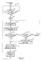
- FIG. 3is a flow chart for a process performed within the controller at the vehicle of FIG. 1;
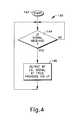
- FIG. 4is a process formed within a controller at a portable transceiver shown in FIG. 1;
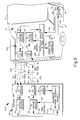
- FIG. 5is a block diagram of a second embodiment of a system in accordance with the present invention, and an associated vehicle;
- FIG. 6is a function block diagram of a controller at the vehicle shown in FIG. 5;
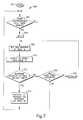
- FIG. 7is a flow chart for a processed performed within the controller at the vehicle shown within FIG. 5;
- FIG. 8is a block diagram of a third embodiment of a system in accordance with the present invention, and an associated vehicle.
- FIG. 1A system 10 , in accordance with the present invention, and an associated vehicle 12 are shown in FIG. 1 .
- the vehicle 12includes an interior 14 that is enclosed by at least one access door 16 .
- the door 16is movable and has a handle 18 that is manually actuatable to cause actuation of a latch mechanism (not shown). Latch mechanism actuation releases the door to open such that entrance may be gained into the interior 14 of the vehicle 12 .
- the door 16is a securable entrance cover that closes an entranceway into the vehicle interior 14 and the vehicle interior is a secured area.
- a lock mechanism 22maintains the latch mechanism in a latched condition and prevents opening of the door 16 .
- latch mechanisms and lock mechanismscan be used.
- the system 10includes an automatic-unlock transceiver/control unit 24 located at the vehicle 12 .
- the automatic-unlock transceiver/control unit 24is referred to as the vehicle-based unit 24 . It is to be appreciated that the vehicle-based unit 24 is shown in a disproportionate size in FIG. 1 with regard to the vehicle 12 for illustration purposes.
- the vehicle-based unit 24is operatively connected 26 to the lock mechanism 22 and controls operation of the lock mechanism.
- the vehicle-based unit 24emits an interrogation signal 28 and also receives a response signal 30 .
- An identification transceiver 34is located on an authorized person (only a hand 36 of the authorized person is shown by the door handle 18 ).
- the identification transceiver 34may take the form of a button, a tag, or a fob that the authorized person carries in their pocket, in their purse, or secured to their key chain.
- the identification transceiver 34is a portable transceiver that is carried by the authorized person.
- the identification transceiver 34is referred to as the portable transceiver 34 . It is to be appreciated that the portable transceiver 34 is not illustrated in FIG. 1 as being to scale with the vehicle 12 , the hand 36 of the authorized person, etc. for illustrative purposes.
- the portable transceiver 34receives the interrogation signal 28 from the vehicle-based unit 24 . In response to reception of the interrogation signal 28 , the portable transceiver 34 emits the response signal 30 as a request (e.g., entry command) for the authorized person to gain access into the interior 14 of the vehicle 12 .
- the response signal 30conveys an appropriate security code, which identifies the portable transceiver 34 and thus identifies the bearer of the portable transceiver as the person that is authorized to enter the vehicle 12 .
- the vehicle-based unit 24In response to reception of the response signal 30 , the vehicle-based unit 24 provides a signal to the lock mechanism 22 that causes actuation of the lock mechanism to an unlock condition.
- the authorized personcan gain entry into the interior 14 of the vehicle 12 without manually operating any unlock device. Specifically, the authorized person does not need to manually turn a key, manually operate a hand-held transmitter, or manually enter a code on a touch pad at the vehicle 12 , or the like.
- the vehicle-based unit 24 and the portable transceiver 34are in a communication arrangement for performing the interrogation and automatic unlock sequence for the authorized person.
- the automatic unlockingis a passive function. In the illustrated example, the passive function is performed at a vehicle (i.e., vehicle 12 ) and is thus a passive vehicle function, with the function being unlocking of the door 16 , the system 10 is a passive entry system.
- the vehicle-based unit 24does not continuously output interrogation signals. Such a continuous output of interrogation signals is associated with an unneeded consumption of vehicle power (i.e., a drain on a vehicle battery). Thus, the vehicle-based unit 24 utilizes an initiation stimulus that is indicative of the authorized person being in close proximity to the vehicle 12 and desiring entrance into the vehicle.
- a sensor 38is provided in conjunction with the door handle 18 and operatively connected 40 to the vehicle-based unit 24 such that when the hand 36 of the authorized person reaches to actuate the handle, the interrogation sequence is initiated (i.e., the vehicle-based unit 24 outputs the interrogation signal 28 ).
- the vehicle-based unit 24outputs the interrogation signal 28 .
- One example of a system that initiates a passive entry interrogation when the authorized person reaches to actuate a vehicle door handleis disclosed in U.S. patent application Ser. No. 09/300,415, filed Apr. 27, 1999.
- the authorized personmay actuate a pushbutton on the vehicle.
- the vehicle-based unit 24selects a RF frequency at which the portable transceiver 34 is to provide the response signal 30 . Selection of RF frequency permits avoidance of noisy frequency channels.
- the vehicle-based unit 24provides the information regarding the selected RF frequency to the portable transceiver 34 as part of the interrogation signal 28 that is a low frequency (LF) magnetic field signal (e.g., 125 kHz).
- LFlow frequency
- the magnetic field signal strengthis related to the inverse of the cube of the distance
- RF signal strengthis related to the inverse of the square of the distance.
- a magnetic interrogation signalis less likely to reflect and propagate over a great distance and reach a portable transceiver located a relatively great distance from a vehicle.
- the magnetic fieldis somewhat impervious to interference.
- different response signal frequenciesi.e., the RF frequency at which the identification transceiver responds to the vehicle-based unit
- different interrogation signal frequenciesi.e., the LF frequency at which the vehicle-based unit 24 provides the selected RF frequency information to the portable transceiver 34
- the response signals from the portable response transceiver 34are RF signals, as opposed to LF signals like the LF interrogation signals, to prevent undue power consumption at the portable transceiver.
- the portable transceiver 34includes a magnetic field antenna 42 for receiving the LF magnetic field signal 28 .
- LF receive circuitry 44is operatively connected 46 to the LF antenna 42 and is also operatively connected 48 to a controller 50 .
- the LF receive circuitry 44conveys the information contained within the LF interrogation signal 28 to the controller 50 .
- the information contained within the LF signal 28includes a request or stimulus (e.g., a wake-up) for the portable transceiver 34 to output its identification (i.e., security code) via the RF response signal 30 .
- the information provided via the LF signal 28also contains data that conveys the RF frequency at which the portable transceiver 34 is to output the RF response signal 30 .
- Tunable RF transmit circuitry 52is operatively connected 54 to the controller 50 and is also operatively connected 56 to a RF antenna 58 .
- the controller 50provides a frequency control signal to the RF transmit circuitry 52 that represents the selected RF frequency provided to the portable transceiver 34 via the LF signal 28 .
- the frequency control signalis utilized within the RF transmit circuitry 52 to adjust or tune the frequency at which the RF response signal 30 occurs.
- Tunable RF transmit circuitryis known in the art and is not discussed herein in detail.
- One example of a device that has a tunable or adjustable frequency outputis disclosed within U.S. patent application Ser. No. 09/055,830, filed Apr. 6, 1998.
- the security code identification of the portable transceiver 34is retrieved by the controller 50 from an identification memory 60 that is operatively connected 62 to the controller.
- the controller 50provides a message packet to the RF transmit circuitry 52 that contains the security code identification of the portable transceiver 34 .
- An electrical stimulus signal that conveys the security code identificationis output from the RF transmit circuitry 52 .
- the stimulus signalcauses the RF antenna 58 to output (e.g., broadcast) the RF response signal 30 conveying the security code identification at the selected RF frequency.
- the connection 40 from the sensor 38 at the door handle 18extends to a controller 66 .
- the controller 66receives the signal from sensor 38 that is indicative of the hand 36 reaching to actuate the door handle 18 .
- the controller 66makes a selection regarding the RF frequency that the portable transceiver 34 is to use for the RF response signal 30 and begins the interrogation process.
- the selection of the RF frequencymay be done via several techniques and is discussed below.
- the controller 66is operatively connected 68 to LF transmit circuitry 70 and, in turn, the LF transmit circuitry is operatively connected 72 to a LF antenna 74 .
- the controller 66provides a message package to the LF transmit circuitry 70 that contains the interrogation initiation request and data that conveys the selected RF frequency at which the portable transceiver 34 is to respond.
- An electrical stimulus signal from the LF transmit circuitry 70 to the LF antenna 74conveys the message information and stimulates the LF antenna 74 to output (e.g., broadcast) the LF signal 28 .
- a RF antenna 76 of the vehicle-based unit 24is operatively connected 78 to RF receive circuitry 80 , which is in turn operatively connected 82 to the controller 66 .
- the RF receive circuitry 80is tunable or adjustable.
- the controller 66provides a frequency control signal to the RF receive circuitry 80 such that the RF receive circuitry is tuned or adjusted.
- the RF receive circuitry 80is tuned to the RF frequency at which the controller 66 has selected for the portable transceiver 34 to respond.
- an electrical signalis provided to the RF receive circuitry 80 .
- the RF receive circuitry 80conveys the message packet that contains the security code identification of the portable transceiver 34 to the controller 66 .
- the controller 66processes the provided security code identification.
- a door lock control 84is operatively connected 86 to the controller 66 .
- the connection 26 to the lock mechanism 22extends from the door lock control 84 . If the security code is verified, the controller 66 provides an appropriate signal to the door lock control 84 , which in turn actuates the lock mechanism 22 to an unlocked condition.
- the controller 66 of the vehicle-based unit 24 of the embodiment shown in FIG. 1makes a selection based upon determinations of which of several possible frequency channels would likely result in receipt of the response signal 30 or at least have the best chance of causing the receipt of the response signal. In other words, the controller 66 selects a RF frequency based upon an acceptable or highest likelihood that the RF response signal 30 at the selected frequency from the portable transceiver 34 will reach the vehicle-based unit 24 . Any of several techniques and/or determinations can be utilized by the controller 66 to conclude that selection of a particular frequency should result in reception of the RF response signal 30 at the vehicle-based unit 24 .
- the controller 66For processing the information conveyed via the RF response signal 30 , the controller 66 includes a decrypt/identification verification function portion 88 that receives the signal output from the RF receive circuitry that conveys the message (i.e., the security code identification) of the response signal. The message is decrypted using one or more decryption keys to provide the received message in a non-encrypted form. The security code identification provided within the received message is then compared to a security code retrieved from an identification memory 90 . If the security codes match (i.e., the received message is authentic), the decrypt/identification verification function portion 88 outputs the signal to the door lock control 84 to cause unlocking of the vehicle door 16 .
- the decrypt/identification verification function portion 88outputs the signal to the door lock control 84 to cause unlocking of the vehicle door 16 .
- the controller 66includes a frequency selection control function portion 92 .
- Different noise levelscan occur at different frequencies.
- a noise monitor function portion 94receives the output from the RF receive circuitry 80 and provides an input signal to the frequency selection control function portion 92 .
- the signal from the noise monitor function portion 94has a signal characteristic that is indicative of the noise that is currently being received at the RF antenna 76 and conveyed to the RF receive circuitry 80 .
- the signal from the noise monitor function portion 94is a voltage that is proportional to the received signal noise.
- the received signal noisewill be associated with the frequency that the RF receive circuitry 80 is currently tuned to receive.
- different predetermined frequenciesi.e., channels
- the frequency selection control function portion 92selects a frequency channel that has noise below a predetermined threshold level. If none of the predetermined frequency channels has a noise level below the threshold level, the frequency selection control function portion 92 make a selection based upon the least amount of noise.
- noise on the various potential frequency channelsis monitored and selection of a RF frequency channel occur just prior to the system 10 engaging in the exchange of signals for the interrogation process that determines whether to permit entrance into the vehicle 12 .
- a frequency provision function portion 96 and a frequency memory 98are provided within the controller 66 .
- the frequency memory 98contains stored information regarding the predefined frequencies or channels. The information stored in the memory 98 is utilized by the frequency provision function portion 96 to tune (e.g., program) the RF receive circuitry 80 to one of the predetermined frequencies.
- Tuninge.g., programming the RF receive circuitry 80 to a specific RF frequency allows the noise at the specific frequency to be monitored.
- the frequency selection control function portion 92commands the frequency provision function portion 96 to sequence through the predetermined frequency channels while noise is monitored.
- the frequency selection control function portion 92receives the triggering signal from the door handle sensor 38 and in response to receipt of the triggering signal initiates the procedure with regard to sequencing through the predetermined frequencies and the selection of the RF frequency. As the RF receive circuitry 80 is sequentially tuned to each frequency, the noise at each frequency is monitored.
- tuning the RF receive circuitry 80 to the selected frequency for the interrogation sequenceallows the RF response signal 30 at the selected frequency to be received.
- Tuning the RF receive circuitry 80 to the selected frequencyoccurs, naturally, after the frequency is selected and contemporaneously with the frequency provision function means providing the selected RF frequency to the LF transmit circuitry 70 in the form of a data string (e.g., a message package).
- the frequency selection control function portion 92when the door handle sensor 38 senses the hand 36 reaching for the handle, the triggering signal from the door handle sensor is provided to the frequency selection control function portion 92 .
- the frequency provision function portion 96is commanded to sequentially tune the RF receive circuitry 80 while the frequency selection control function portion 92 monitors the noise.
- the first frequency channel that has a noise below the certain threshold levelis selected. If, after the RF receive circuitry 80 has been sequential tuned to all of the predetermined frequency channels, none of the frequency channels had noise below the certain threshold, then the frequency channel with the least noise is selected.
- the frequency selection control function portion 92selects a frequency for use in RF communication, a signal is provided to the frequency provision function portion 96 that causes the selected frequency to be provided to the RF receive circuitry 80 as the setting and to the LF transmit circuitry 70 as the data.
- step 104it is determined whether the interrogation procedure is to be initiated. In the specific example, step 104 determines if the signal provided from the door handle sensor 38 indicates the hand 36 reaching for the door handle. If the determination at step 104 is negative (i.e., the door handle sensor 38 has not yet indicated a hand reaching for the handle), the process 100 loops back to repeat step 104 .
- step 106the variable N is set equal to one.
- the variable Nrepresents the channel number (i.e., predetermined frequency) to be used for RF communication.
- the RF receive circuitryis set to receive the frequency N and the noise at frequency N is monitored.
- the noise level associated with frequency Nis determined.
- step 112determines whether the determination at step 112 is affirmative (i.e., the noise is sufficiently LOW at frequency N).
- the process 100proceeds to step 114 .
- the frequency Nis the selected frequency.
- the RF receive circuitry 80is tuned to the selected frequency N and the frequency N is output to the LF transmit circuitry 70 as data.
- step 116information that is received via the RF response signal 30 at the selected frequency N is processed such that the provided identification is verified. If the message is authentic (i.e., security code is verified), the door 16 is unlocked.
- the process 100loops back to step 114 to again monitor for an initiation of an interrogation sequence.
- step 112if the noise level for the selected frequency N is not below the predetermined tolerance level, the process 100 proceeds from step 112 to step 118 .
- step 118it is determined whether all of the potential predetermined frequency channels have been tested. If the determination at step 118 is negative (i.e., all of the frequency channels have not yet been tested), the process 100 proceeds from step 118 to step 120 .
- step 120the variable N is increased by 1. Thus, the value N is increased such that the next frequency channel is utilized in the noise determination process.
- the process 100proceeds to step 108 where the RF receive circuitry is tuned to the new frequency N.
- step 118the process 100 proceeds from step 118 to step 122 .
- the frequency selection control function portion 92makes a determination as to which of the frequencies had the least noise (despite the fact that each frequency had a level of noise above the tolerance level).
- the variable Nis assigned the number that is associated with the frequency that had the least noise.
- the process 100proceeds from step 122 to step 114 .
- step 114the RF receive circuitry 80 is tuned to the selected frequency and the selected frequency is output as data to the LF transmit circuitry 70 .
- step 116as previously described.
- step 144it is determined if the LF signal is received. If the determination at step 144 is negative (i.e., the LF signal is not yet receive), the process 140 loops to repeat the step 144 . If the determination at step 144 is affirmative (i.e., the LF signal is received), the RF response signal 30 is output to convey the security code identification at the RF frequency that is provided via the data contained within the LF signal 28 . Upon completion of step 146 , the process 140 loops back to step 144 .
- the selection of a RF frequency at a vehicle-based unitneed not include a determination regarding which predetermined frequency is a suitable frequency or a determination of which of the predetermined frequencies has the least noise.
- a vehicle-based unitsequentially selects RF frequencies that are provided to a portable transceiver for RF response signals from the portable transceiver. The vehicle-based unit continues to select frequencies until a RF response signal from the portable transceiver reaches the vehicle-based unit.
- the passive entry system 210includes a portable transceiver 34 that is identical to the portable transceiver 34 shown in the embodiment of FIG. 1 . Accordingly, the structural elements of the portable transceiver 34 (FIG. 5) for the second embodiment are not discussed in detail and the same reference numerals are used for the portable transceiver shown in FIG. 5 .
- the vehicle-based unit 224 of the system 210has several components that are identical to corresponding components within the first embodiment of FIG. 1 .
- the same reference numeralsare used in FIG. 5 for the components that are the same as in the embodiment of FIG. 1 .
- the door handle sensor 38provides a signal indicative of the hand 36 reaching to actuate the door handle 18 .
- the door lock control 84provides the signal to the door lock mechanism 22 .
- the LF antenna 74is operatively connected 72 to LF transmit circuitry 70 for outputting LF signals 228 , 228 ′ that convey RF frequency information as data.
- the RF antenna 76is operatively connected 78 to RF receive circuitry 80 .
- the RF receive circuitry 80is tunable to receive RF response signals 230 , 230 ′ at each of the predetermined frequencies.
- a controller 266 of the embodiment of FIG. 5merely selects a RF frequency channel from a predetermined group of frequency channels.
- the current selected RF frequencyis provided to the portable transceiver 34 for the portable transceiver to attempt and reach the vehicle-based unit 224 using the current selected RF frequency.
- the controller 266does not include a portion that monitors noise on the predetermined frequency channels and does not include a portion that makes a determination as to a suitable or best frequency.
- the first LF signal 228is output from the vehicle-based unit 224 and conveys a first selected RF frequency as data.
- the portable transceiver 34receives the first LF signal 228 , and in response thereto, outputs the first RF response signal 230 that conveys the security code identification at the first selected RF frequency.
- the first RF response signal 230is not received at the vehicle-based unit 224 due to some external influence 232 , such as interference noise.
- the lack of reception of the first RF response signal 230causes the vehicle-based unit 224 to output the second LF signal 228 ′ that coveys a second selected RF frequency as data.
- the vehicle-based unit 224presumes that the first selected frequency channel has an excessive noise level or the like because a response was not received.
- the second LF signal 228 ′causes the output of the second RF response signal 230 ′ that conveys the security code identification at the second selected frequency.
- the second RF response signal 230 ′is received at the vehicle-based unit 224 . It to be appreciated that several RF frequencies can be provided via LF signals and used to output RF response signals before a response signal reaches the vehicle-based unit 224 .
- the controller 266 of the vehicle-based unit 224 of the embodiment of FIG. 5includes a decrypt/identification verification function portion 288 that is operatively connected to the RF receive circuitry 80 and a security code identification memory 290 for comparing security codes.
- the decrypt/identification verification function portion 288is operatively connected to the door lock control 84 to provide an unlock command upon verification of a received security code.
- a frequency selection control function portion 292is operatively connected to receive input from the door handle sensor 38 and is also operatively connected to a frequency provision function portion 296 . Predetermined RF frequency values are selected from a frequency memory 298 by the frequency provision function portion 296 . Each RF frequency is provided as a setting to the RF receive circuitry 80 and as data to the LF transmit circuitry 70 .
- a subsequent frequencyis selected if a previous selected frequency does not result in receipt by the vehicle-based unit 224 of a RF response signal at the previously selected frequency.
- the frequenciesare sequentially selected. It is to be appreciated that frequency selection may be based upon any selection pattern, for example the pattern may include selecting a frequency that was last successfully used as a first selection.
- the output of the decrypt/identification verification function portion 288is provided to the frequency selection control function portion 292 such that the frequency selection control function portion is notified that the vehicle-based unit 224 has received the RF response signal at the previously selected frequency.
- the frequency selection control function portion 292instructs the frequency provision function portion 296 to abstain from providing another frequency once the RF response signal is received.
- a timer function portion 294is operatively connected to the frequency provision function portion 296 and the frequency selection control function portion 292 .
- a timed periodis initiated at the timer function portion 294 upon each provision of a frequency to the RF receive circuitry 80 and the LF transmit circuitry 70 by the frequency provision function portion 296 .
- a signalis provided to the frequency selection control function portion 292 upon expiration of each time period.
- Each time periodprovides a length of time within which it can be expected that the portable transceiver 34 will respond with a RF response signal at the selected frequency.
- the frequency selection control function portion 292provides an indication to the frequency provision function portion 296 to advance to a next frequency based upon expiration of the timed period so that the vehicle-based unit 224 proceeds to sequentially output LF signals that convey the selected RF frequencies.
- FIG. 7illustrates a process 300 that is performed within the controller 266 shown in FIG. 6 .
- the process 300is initiated at step 302 and proceeds to step 304 .
- step 304determines whether the determination at step 304 is affirmative (i.e., the hand 36 is reaching to the door handle 18 ).
- the process 300proceeds to step 306 .
- a variable Nis set equal to 1.
- the variable Nis an identifier utilized to identify the predetermined frequency channels.
- the RF receive circuitry 80is set to monitor at the RF frequency N.
- the LF signalis output to convey the data regarding the selected RF frequency N.
- the response periodis the period before expiration of the time period provided by the timer function portion 294 .
- step 312determines whether the RE response signal is received. If the determination at step 312 is affirmative (i.e., the RE response signal is received), the process 300 proceeds to step 314 .
- step 314a security code identification that is provided via the response RF signal is processed and the appropriate action (i.e., unlocking of the door 16 ) is performed.
- the processloops back to step 304 .
- step 312determines whether a RF response signal is not received. If a RF response signal is not received, the determination at step 312 is negative. Upon a negative determination at step 312 , the process 300 proceeds to step 316 . At step 316 , it is determined whether all of the predetermined frequency channels for the RF frequency have been attempted. If the determination at step 316 is negative (i.e., all of the potential frequency channels have not yet been attempted), the process 300 proceeds to step 318 . At step 318 , the variable N is increased by 1. Increasing the variable N by 1 causes the next predetermined frequency to be selected and utilized for the interrogation sequence. Upon completion of step 318 , the process 300 proceeds to step 308 .
- step 316If the determination at step 316 is affirmative (i.e., all of the predetermined frequency channels have been attempted), the process 300 proceeds from step 316 to step 304 .
- An affirmative determination at step 316occurs when the vehicle-based unit 224 has not received any RF response signal despite the fact that all of the predetermined frequency channels have been attempted.
- the LF signals output from a vehicle-based unitmay be output a different LF frequencies.
- the adjustment/selection of the LF frequenciesmay be in a manner similar to the adjustment/selection of the RF response signals described for the other embodiments of the present invention.
- An example of a passive entry system 410 incorporating the adjustment/selection of the LF frequency signalsis shown in FIG. 8 .
- the system 410 of FIG. 8has a portable transceiver 434 that includes RF transmit circuitry 452 and a RF antenna 458 that are utilized to output a RF response signal 430 at a selected frequency.
- a controller 450is operatively connected 454 to the RF transmit circuitry 452 to cause transmission at the selected RF frequency.
- the portable transceiver 434also includes a LF antenna 442 operatively connected 446 to LF receive circuitry 444 that is in turn operatively connected 448 to the controller 450 .
- the portable transceiver 434is capable of receiving LF signals on at least two different frequencies. Accordingly, the LF receive circuitry 444 is adjustable. Adjustment of the LF receive circuitry 444 is shown to be provided by a control signal provided from the controller 450 . However, it is to be appreciated that the LF receive circuitry 444 may provide for its own adjustment (i.e., a toggling setting), or may be configured to simultaneously receive a plurality of LF frequencies.
- the output of the LF receive circuitry 444is provided to the controller 450 .
- the message conveyed via a received LF signalis provided to the controller 450 .
- the controller 450accesses the security code identification from an operatively connected 462 identification memory 460 such that the security code is transmitted via the response signal a the selected RF frequency provided by the received LF signal.
- the vehicle-based unit 424includes a LF antenna 474 and LF transmit circuitry 470 that is operatively connected 468 to a controller 466 .
- the LF transmit circuitry 470is adjustable for providing the output of the plurality of LF signals 428 , 428 ′ at the different LF frequencies.
- the controller 466selects the LF frequency that is to be used for transmission of the LOW frequency signal and provides a frequency setting via a frequency control signal to the LF transmit circuitry 470 . It is contemplated that the controller 466 of the embodiment shown with FIG. 8 may select among predetermined LF frequencies based upon some determination or may merely sequence (e.g., toggle) through the predetermined LF frequencies.
- the controller 466operates similar to the controllers described for the previous embodiments with regard to RF signal selection and identification verification.
- the RF frequency selection processmay include trial of various radio frequencies and/or monitoring for noise on the predefined frequencies.
- the operation of the controller 466thus includes provision of the selected frequency to the RF received circuitry 80 as a setting and provision of the RF frequency as data to the LF transmit circuitry 470 for conveyance to the portable transceiver 434 .
- LF frequenciesare relatively impervious to disruption caused by an external influence 432 , such as noise.
- the ability to change the LF frequency as set forth in embodiment of FIG. 8would permit the system 410 to proceed with an interrogation sequence if the first LF signal 428 at a first frequency was blocked from reaching the portable transceiver 434 by some external influence 432 .
- the second LF signal 428 ′ at the second LF frequencywould then be provided for reception by the portable transceiver 434 .
- the second LF signal 428 ′may convey the same selected RF frequency as the first LF signal 428 or may convey another RF frequency.
- the reception of the second LF signal 428 ′results in the output of the RF response signal 430 at the selected frequency provided via the second LF signal 428 ′.
- the systemmay be used for passive entry at an entrance to some other structure, such a building, and the passive entrance function may include movement of the entranceway cover for the authorized person.
- various other functionsmay be passively controlled.
- the systemmay be used to passively enable engine ignition or to passively actuate the engine ignition for the authorized person.
- ignition functionsi.e., enabling and actuating
- Such use of the systemmay utilize some or all of the disclosed features of the illustrated examples (e.g., non-continuous operation and an associated trigger to initiate interrogation operation).
- the disclosed featuresmay be modified accordingly to fit appropriate circumstances (e.g., use occupancy detection to trigger interrogation for a system that passively controls a vehicle ignition function).
Landscapes
- Engineering & Computer Science (AREA)
- Physics & Mathematics (AREA)
- General Physics & Mathematics (AREA)
- Mechanical Engineering (AREA)
- Computer Networks & Wireless Communication (AREA)
- Lock And Its Accessories (AREA)
Abstract
Description
Claims (21)
Priority Applications (3)
| Application Number | Priority Date | Filing Date | Title |
|---|---|---|---|
| US09/517,829US6801134B1 (en) | 2000-03-02 | 2000-03-02 | System and method for automatic function operation with controlled distance communication having vehicle-based frequency selection |
| FR0102821AFR2808365A1 (en) | 2000-03-02 | 2001-03-01 | Car entry/function authorization remote control system having transmitter sending signal function and receiver detecting signal/controller activating response and selecting remote control frequency for transmission |
| DE10109869.3ADE10109869B4 (en) | 2000-03-02 | 2001-03-01 | System and method for automatic function confirmation with controlled distance communication with vehicle-based frequency selection |
Applications Claiming Priority (1)
| Application Number | Priority Date | Filing Date | Title |
|---|---|---|---|
| US09/517,829US6801134B1 (en) | 2000-03-02 | 2000-03-02 | System and method for automatic function operation with controlled distance communication having vehicle-based frequency selection |
Publications (1)
| Publication Number | Publication Date |
|---|---|
| US6801134B1true US6801134B1 (en) | 2004-10-05 |
Family
ID=24061394
Family Applications (1)
| Application Number | Title | Priority Date | Filing Date |
|---|---|---|---|
| US09/517,829Expired - LifetimeUS6801134B1 (en) | 2000-03-02 | 2000-03-02 | System and method for automatic function operation with controlled distance communication having vehicle-based frequency selection |
Country Status (3)
| Country | Link |
|---|---|
| US (1) | US6801134B1 (en) |
| DE (1) | DE10109869B4 (en) |
| FR (1) | FR2808365A1 (en) |
Cited By (37)
| Publication number | Priority date | Publication date | Assignee | Title |
|---|---|---|---|---|
| US20030013480A1 (en)* | 2001-07-11 | 2003-01-16 | Nec Corporation | Mobile station and frequency band detection method |
| US20030117295A1 (en)* | 2001-12-26 | 2003-06-26 | Toyota Jidosha Kabushiki Kaisha | Remote control system for on-vehicle equipment and remote control method for the same |
| US20030117263A1 (en)* | 2001-09-30 | 2003-06-26 | Gonzales Eric V. | Cardholder interface for an access control system |
| US20040075532A1 (en)* | 2002-10-09 | 2004-04-22 | Honda Giken Kogyo Kabushiki Kaisha | Automatic vehicle door locking/unlocking apparatus |
| US20040150509A1 (en)* | 2003-01-31 | 2004-08-05 | Ford Global Technologies, Inc. | Vehicle high security piggyback modules |
| US20060028353A1 (en)* | 2003-02-20 | 2006-02-09 | Marquardt Gmbh | Locking system, in particular for a motor vehicle |
| US20060125599A1 (en)* | 2004-12-14 | 2006-06-15 | Riad Ghabra | Self-aligning vehicular transmitter system |
| US20060202798A1 (en)* | 2005-03-08 | 2006-09-14 | Siemens Vdo Automotive Corporation | Frequency hopping for passive start and entry systems |
| US20060232378A1 (en)* | 2003-09-26 | 2006-10-19 | Matsushita Electric Industrial Co., Ltd | Door handle device and keyless entry device having the same |
| US20060276186A1 (en)* | 2005-06-06 | 2006-12-07 | Mitsubishi Denki Kabushiki Kaisha | Electronic key apparatus for vehicle |
| US20070139157A1 (en)* | 2004-03-30 | 2007-06-21 | Aisin Seiki Kabushiki Kaisha | On-vehicle radio device |
| US20070160206A1 (en)* | 2006-01-11 | 2007-07-12 | Siemens Vdo Automotive Corporation | Communication method for remote keyless entry system |
| US20070257772A1 (en)* | 2005-03-17 | 2007-11-08 | Jesse Marcelle | Electronic proximity security system |
| US20080055042A1 (en)* | 2006-09-06 | 2008-03-06 | Denso Corporation | Vehicle control system |
| US20080068128A1 (en)* | 2006-08-31 | 2008-03-20 | Riad Ghabra | Keyless passive entry system |
| GB2444368A (en)* | 2006-11-30 | 2008-06-04 | Lear Corp | Frequency selection in system for remote activation of vehicle functions |
| FR2909620A1 (en)* | 2006-12-08 | 2008-06-13 | Renault Sas | Locking/unlocking control method for vehicle, involves transmitting frame of commands, to destination of vehicle at predetermined free frequency, and requiring hop frequency modulation of commands for determining, in advance, free frequency |
| US20080169898A1 (en)* | 2007-01-17 | 2008-07-17 | Denso Corporation | Vehicle control system and method, and component devices |
| US20080197987A1 (en)* | 2007-02-15 | 2008-08-21 | King Ronald O | Keyless entry multi-channel RKE system |
| US20080238637A1 (en)* | 2007-03-30 | 2008-10-02 | Lear Corporation | Wireless access system and method |
| US20080287067A1 (en)* | 2007-04-05 | 2008-11-20 | Kabushiki Kaisha Tokai Rika Denki Seisakusho | System for controlling wireless communication between portable device and communication controller |
| US20080297316A1 (en)* | 2005-12-14 | 2008-12-04 | Nxp B.V. | Method and Rfid Reader for Communication Via Radio Channel |
| US20090160211A1 (en)* | 2007-12-25 | 2009-06-25 | Ford Global Technologies, Inc. | Passive Entry System for Automotive Vehicle Doors |
| WO2009147063A1 (en)* | 2008-06-05 | 2009-12-10 | Continental Automotive Gmbh | Apparatus and method for reducing the current consumption of a control circuit |
| CN101295412B (en)* | 2007-04-23 | 2012-07-25 | 李尔公司 | Remote control reactivation |
| US20120309299A1 (en)* | 2010-02-19 | 2012-12-06 | Denso Corporation | Receiver, wireless communication system, and receiving method |
| US8627433B2 (en)* | 2011-09-30 | 2014-01-07 | GM Global Technology Operations LLC | System and method for authenticating a request for access to a secured device |
| US20140320262A1 (en)* | 2013-04-30 | 2014-10-30 | Hyundai Mobis Co., Ltd. | Smartkey system and operating method thereof |
| GB2513713A (en)* | 2013-04-25 | 2014-11-05 | Ford Global Tech Llc | Mitigation of LF interference from adjacent vehicles also using LF approach detection system |
| US20150371467A1 (en)* | 2014-06-24 | 2015-12-24 | Leadot Innovation, Inc. | Lock control method |
| WO2016157699A1 (en)* | 2015-03-31 | 2016-10-06 | 株式会社デンソー | Electronic key system for vehicle |
| US20170098335A1 (en)* | 2015-10-02 | 2017-04-06 | Stanley Security Solutions, Inc. | Cardless access control with electronic locks using smartphones |
| EP3357767A1 (en)* | 2017-02-07 | 2018-08-08 | Toyota Jidosha Kabushiki Kaisha | Vehicle control system |
| EP3031676B1 (en)* | 2014-12-10 | 2019-05-15 | Huf Hülsbeck & Fürst GmbH & Co. KG | Device for a safety system of a vehicle |
| DE102014200545B4 (en) | 2013-01-28 | 2019-06-13 | Omron Automotive Electronics Co., Ltd. | Communication system and communication device |
| US10513245B2 (en)* | 2018-02-12 | 2019-12-24 | FELL Technology AS | Secure key acknowledgement—frequency dilution |
| US11319732B2 (en)* | 2018-08-17 | 2022-05-03 | Ford Global Technologies, Llc | Pre-fluxing motors of vehicle door e-latches |
Families Citing this family (4)
| Publication number | Priority date | Publication date | Assignee | Title |
|---|---|---|---|---|
| DE10259590A1 (en)* | 2002-12-19 | 2004-07-01 | Daimlerchrysler Ag | Vehicle security system |
| DE10320786A1 (en)* | 2003-05-09 | 2004-12-02 | Hella Kgaa Hueck & Co. | Car remote unlocking authentication unit has frequency scanner to detect carrier parameters for challenge response procedure |
| DE102006029339A1 (en)* | 2005-11-03 | 2007-05-10 | Teratron Gmbh | Monitoring the release of a computer |
| DE102006058854B4 (en)* | 2006-12-13 | 2017-08-03 | Volkswagen Ag | Method for actuating devices to be opened of a motor vehicle and corresponding device and corresponding motor vehicle |
Citations (17)
| Publication number | Priority date | Publication date | Assignee | Title |
|---|---|---|---|---|
| US4616364A (en) | 1984-06-18 | 1986-10-07 | Itt Corporation | Digital hopped frequency, time diversity system |
| US4644347A (en) | 1983-08-10 | 1987-02-17 | Motorola, Inc. | Multiple frequency message system |
| US4688036A (en) | 1983-11-29 | 1987-08-18 | Nissan Motor Company, Limited | Keyless entry system for automotive vehicle with power consumption saving feature |
| US4794268A (en) | 1986-06-20 | 1988-12-27 | Nissan Motor Company, Limited | Automotive keyless entry system incorporating portable radio self-identifying code signal transmitter |
| US4811013A (en) | 1985-10-28 | 1989-03-07 | Kokusan Kinzoku Kogyo Kabushiki Kaisha | Vehicle use-locking and unlocking system |
| US5142691A (en) | 1991-04-05 | 1992-08-25 | Motorola, Inc. | Frequency management system |
| US5303259A (en) | 1991-11-07 | 1994-04-12 | Loveall Peter S | Frequency-hopped electronic signal transmitter |
| US5319364A (en) | 1988-05-27 | 1994-06-07 | Lectron Products, Inc. | Passive keyless entry system |
| US5379033A (en) | 1991-08-09 | 1995-01-03 | Alps Electric Co., Ltd. | Remote control device |
| US5428818A (en) | 1991-11-10 | 1995-06-27 | Motorola Inc. | Method and apparatus for reducing interference in a radio communication link of a cellular communication system |
| US5438699A (en) | 1992-06-09 | 1995-08-01 | Coveley; Michael | Adaptive system for self-tuning a receiver in an RF communication system |
| US5499388A (en) | 1993-10-20 | 1996-03-12 | Polk's Model Craft Hobbies, Inc. | Radio with frequency scanning and interference detection capability for remote controlled model aircraft |
| US5682135A (en) | 1995-05-04 | 1997-10-28 | Kiekert Ag | Motor vehicle security system |
| US5933074A (en)* | 1998-06-23 | 1999-08-03 | Ut Automotive Dearborn, Inc. | Remote control transmitter broadcasting RF signals conveying plural information components |
| US6323566B1 (en)* | 1996-10-10 | 2001-11-27 | Texas Instruments Incorported | Transponder for remote keyless entry systems |
| US6389275B1 (en)* | 1998-06-30 | 2002-05-14 | Omron Corporation | Signal receiver and method thereof, transceiver, and network system |
| US6603388B1 (en)* | 1999-08-17 | 2003-08-05 | Motorola, Inc. | Security system and method |
Family Cites Families (6)
| Publication number | Priority date | Publication date | Assignee | Title |
|---|---|---|---|---|
| DE4329697C2 (en)* | 1993-09-02 | 1995-10-05 | Siemens Ag | Remote controllable access control device |
| US5963145A (en)* | 1996-02-26 | 1999-10-05 | Universal Electronics Inc. | System for providing wireless pointer control |
| EP0848123B1 (en)* | 1996-10-10 | 2004-12-08 | Texas Instruments Deutschland Gmbh | A remote keyless entry system |
| US6091343A (en)* | 1997-12-18 | 2000-07-18 | Prince Corporation | Trainable RF transmitter having expanded learning capabilities |
| GB9816170D0 (en)* | 1997-12-20 | 1998-09-23 | Rover Group | A security system |
| AU763156B2 (en)* | 1998-05-11 | 2003-07-17 | Robert Bosch Gmbh | A system and method of communication |
- 2000
- 2000-03-02USUS09/517,829patent/US6801134B1/ennot_activeExpired - Lifetime
- 2001
- 2001-03-01FRFR0102821Apatent/FR2808365A1/enactivePending
- 2001-03-01DEDE10109869.3Apatent/DE10109869B4/ennot_activeExpired - Fee Related
Patent Citations (17)
| Publication number | Priority date | Publication date | Assignee | Title |
|---|---|---|---|---|
| US4644347A (en) | 1983-08-10 | 1987-02-17 | Motorola, Inc. | Multiple frequency message system |
| US4688036A (en) | 1983-11-29 | 1987-08-18 | Nissan Motor Company, Limited | Keyless entry system for automotive vehicle with power consumption saving feature |
| US4616364A (en) | 1984-06-18 | 1986-10-07 | Itt Corporation | Digital hopped frequency, time diversity system |
| US4811013A (en) | 1985-10-28 | 1989-03-07 | Kokusan Kinzoku Kogyo Kabushiki Kaisha | Vehicle use-locking and unlocking system |
| US4794268A (en) | 1986-06-20 | 1988-12-27 | Nissan Motor Company, Limited | Automotive keyless entry system incorporating portable radio self-identifying code signal transmitter |
| US5319364A (en) | 1988-05-27 | 1994-06-07 | Lectron Products, Inc. | Passive keyless entry system |
| US5142691A (en) | 1991-04-05 | 1992-08-25 | Motorola, Inc. | Frequency management system |
| US5379033A (en) | 1991-08-09 | 1995-01-03 | Alps Electric Co., Ltd. | Remote control device |
| US5303259A (en) | 1991-11-07 | 1994-04-12 | Loveall Peter S | Frequency-hopped electronic signal transmitter |
| US5428818A (en) | 1991-11-10 | 1995-06-27 | Motorola Inc. | Method and apparatus for reducing interference in a radio communication link of a cellular communication system |
| US5438699A (en) | 1992-06-09 | 1995-08-01 | Coveley; Michael | Adaptive system for self-tuning a receiver in an RF communication system |
| US5499388A (en) | 1993-10-20 | 1996-03-12 | Polk's Model Craft Hobbies, Inc. | Radio with frequency scanning and interference detection capability for remote controlled model aircraft |
| US5682135A (en) | 1995-05-04 | 1997-10-28 | Kiekert Ag | Motor vehicle security system |
| US6323566B1 (en)* | 1996-10-10 | 2001-11-27 | Texas Instruments Incorported | Transponder for remote keyless entry systems |
| US5933074A (en)* | 1998-06-23 | 1999-08-03 | Ut Automotive Dearborn, Inc. | Remote control transmitter broadcasting RF signals conveying plural information components |
| US6389275B1 (en)* | 1998-06-30 | 2002-05-14 | Omron Corporation | Signal receiver and method thereof, transceiver, and network system |
| US6603388B1 (en)* | 1999-08-17 | 2003-08-05 | Motorola, Inc. | Security system and method |
Non-Patent Citations (3)
| Title |
|---|
| U.S. LeMense et al. patent application Ser. No. 09/055,751, filed Apr. 6, 1998 entitled "Apparatus and Method for Remote Convenience Message Reception and Control Utilizing Frequency Diversity." |
| U.S. LeMense et al. patent application Ser. No. 09/055,830, filed Apr. 6, 1998 entitled "Apparatus and Method for Remote Convenience Message Transmission and Control Utilizing Frequency Diversity." |
| U.S. Steiner patent application Ser. No. 09/300,415, filed Apr. 27, 1999 entitled "System and Method for Automatic Vehicle Unlock Initiated Via Beam Interruption." |
Cited By (70)
| Publication number | Priority date | Publication date | Assignee | Title |
|---|---|---|---|---|
| US20030013480A1 (en)* | 2001-07-11 | 2003-01-16 | Nec Corporation | Mobile station and frequency band detection method |
| US20030117263A1 (en)* | 2001-09-30 | 2003-06-26 | Gonzales Eric V. | Cardholder interface for an access control system |
| US7289764B2 (en)* | 2001-09-30 | 2007-10-30 | Harrow Products, Llc | Cardholder interface for an access control system |
| US7061368B2 (en)* | 2001-12-26 | 2006-06-13 | Toyota Jidosha Kabushiki Kaisha | Remote control system for on-vehicle equipment and remote control method for the same |
| US20030117295A1 (en)* | 2001-12-26 | 2003-06-26 | Toyota Jidosha Kabushiki Kaisha | Remote control system for on-vehicle equipment and remote control method for the same |
| US20040075532A1 (en)* | 2002-10-09 | 2004-04-22 | Honda Giken Kogyo Kabushiki Kaisha | Automatic vehicle door locking/unlocking apparatus |
| US6924735B2 (en)* | 2002-10-09 | 2005-08-02 | Honda Giken Kogyo Kabushiki Kaisha | Automatic vehicle door locking/unlocking apparatus |
| US7034714B2 (en)* | 2003-01-31 | 2006-04-25 | Ford Global Technologies, Llc | Vehicle high security piggyback modules |
| US20040150509A1 (en)* | 2003-01-31 | 2004-08-05 | Ford Global Technologies, Inc. | Vehicle high security piggyback modules |
| US20060028353A1 (en)* | 2003-02-20 | 2006-02-09 | Marquardt Gmbh | Locking system, in particular for a motor vehicle |
| US7667571B2 (en)* | 2003-02-20 | 2010-02-23 | Marquardt Gmbh | Locking system, in particular for a motor vehicle |
| US20060232378A1 (en)* | 2003-09-26 | 2006-10-19 | Matsushita Electric Industrial Co., Ltd | Door handle device and keyless entry device having the same |
| JPWO2005098177A1 (en)* | 2004-03-30 | 2008-07-31 | アイシン精機株式会社 | In-vehicle wireless device |
| US20070139157A1 (en)* | 2004-03-30 | 2007-06-21 | Aisin Seiki Kabushiki Kaisha | On-vehicle radio device |
| US20090309753A1 (en)* | 2004-12-14 | 2009-12-17 | Lear Corporation | Self-Aligning Vehicular Transmitter System |
| US7986960B2 (en) | 2004-12-14 | 2011-07-26 | Lear Corporation | Self-aligning vehicular transmitter system |
| US20060125599A1 (en)* | 2004-12-14 | 2006-06-15 | Riad Ghabra | Self-aligning vehicular transmitter system |
| US7580696B2 (en) | 2004-12-14 | 2009-08-25 | Lear Corporation | Self-aligning vehicular transmitter system |
| US20060202798A1 (en)* | 2005-03-08 | 2006-09-14 | Siemens Vdo Automotive Corporation | Frequency hopping for passive start and entry systems |
| JP2008538265A (en)* | 2005-03-08 | 2008-10-16 | シーメンス ヴィディーオー オートモーティヴ コーポレイション | Frequency hopping for passive start / ride systems |
| US20070257772A1 (en)* | 2005-03-17 | 2007-11-08 | Jesse Marcelle | Electronic proximity security system |
| US20060276186A1 (en)* | 2005-06-06 | 2006-12-07 | Mitsubishi Denki Kabushiki Kaisha | Electronic key apparatus for vehicle |
| US20080297316A1 (en)* | 2005-12-14 | 2008-12-04 | Nxp B.V. | Method and Rfid Reader for Communication Via Radio Channel |
| WO2007082258A3 (en)* | 2006-01-11 | 2007-10-25 | Siemens Vdo Automotive Corp | Communication method for remote keyless entry system |
| US20070160206A1 (en)* | 2006-01-11 | 2007-07-12 | Siemens Vdo Automotive Corporation | Communication method for remote keyless entry system |
| US20080068128A1 (en)* | 2006-08-31 | 2008-03-20 | Riad Ghabra | Keyless passive entry system |
| US20080055042A1 (en)* | 2006-09-06 | 2008-03-06 | Denso Corporation | Vehicle control system |
| US8102241B2 (en)* | 2006-09-06 | 2012-01-24 | Denso Corporation | Vehicle control system |
| GB2444368B (en)* | 2006-11-30 | 2010-06-30 | Lear Corp | Multichannel passive vehicle activation system |
| US20080174446A1 (en)* | 2006-11-30 | 2008-07-24 | Lear Corporation | Multi-channel passive vehicle activation system |
| GB2444368A (en)* | 2006-11-30 | 2008-06-04 | Lear Corp | Frequency selection in system for remote activation of vehicle functions |
| FR2909620A1 (en)* | 2006-12-08 | 2008-06-13 | Renault Sas | Locking/unlocking control method for vehicle, involves transmitting frame of commands, to destination of vehicle at predetermined free frequency, and requiring hop frequency modulation of commands for determining, in advance, free frequency |
| US20080169898A1 (en)* | 2007-01-17 | 2008-07-17 | Denso Corporation | Vehicle control system and method, and component devices |
| US8138894B2 (en)* | 2007-01-17 | 2012-03-20 | Denso Corporation | Vehicle control system and method, and component devices |
| CN101262532B (en)* | 2007-02-15 | 2012-11-28 | 李尔公司 | Keyless entry multi-channel rke system |
| US9085281B2 (en)* | 2007-02-15 | 2015-07-21 | Lear Corporation | Keyless entry multi-channel RKE system |
| US20080197987A1 (en)* | 2007-02-15 | 2008-08-21 | King Ronald O | Keyless entry multi-channel RKE system |
| US7683756B2 (en) | 2007-03-30 | 2010-03-23 | Lear Corporation | Wireless access system and method |
| US20080238637A1 (en)* | 2007-03-30 | 2008-10-02 | Lear Corporation | Wireless access system and method |
| CN101280649B (en)* | 2007-04-05 | 2013-04-17 | 株式会社东海理化电机制作所 | System for controlling wireless communication between portable device and communication controller |
| US8532576B2 (en)* | 2007-04-05 | 2013-09-10 | Kabushiki Kaisha Tokai Rika Denki Seisakusho | System for controlling wireless communication between portable device and communication controller |
| US20080287067A1 (en)* | 2007-04-05 | 2008-11-20 | Kabushiki Kaisha Tokai Rika Denki Seisakusho | System for controlling wireless communication between portable device and communication controller |
| CN101295412B (en)* | 2007-04-23 | 2012-07-25 | 李尔公司 | Remote control reactivation |
| US20090160211A1 (en)* | 2007-12-25 | 2009-06-25 | Ford Global Technologies, Inc. | Passive Entry System for Automotive Vehicle Doors |
| US8451087B2 (en)* | 2007-12-25 | 2013-05-28 | Ford Global Technologies, Llc | Passive entry system for automotive vehicle doors |
| CN102057582B (en)* | 2008-06-05 | 2014-02-26 | 大陆汽车有限公司 | Apparatus and method for reducing current consumption of a control circuit |
| US20110084816A1 (en)* | 2008-06-05 | 2011-04-14 | Stephanie Briese | Apparatus and method for reducing the current consumption of a control circuit |
| WO2009147063A1 (en)* | 2008-06-05 | 2009-12-10 | Continental Automotive Gmbh | Apparatus and method for reducing the current consumption of a control circuit |
| CN102057582A (en)* | 2008-06-05 | 2011-05-11 | 欧陆汽车有限责任公司 | Apparatus and method for reducing current consumption of a control circuit |
| US8588715B2 (en)* | 2010-02-19 | 2013-11-19 | Toyota Jidosha Kabushiki Kaisha | Receiver, wireless communication system, and receiving method |
| US20120309299A1 (en)* | 2010-02-19 | 2012-12-06 | Denso Corporation | Receiver, wireless communication system, and receiving method |
| US8627433B2 (en)* | 2011-09-30 | 2014-01-07 | GM Global Technology Operations LLC | System and method for authenticating a request for access to a secured device |
| DE102014200545B4 (en) | 2013-01-28 | 2019-06-13 | Omron Automotive Electronics Co., Ltd. | Communication system and communication device |
| GB2513713A (en)* | 2013-04-25 | 2014-11-05 | Ford Global Tech Llc | Mitigation of LF interference from adjacent vehicles also using LF approach detection system |
| GB2513713B (en)* | 2013-04-25 | 2017-03-15 | Ford Global Tech Llc | Mitigation of LF interference from adjacent vehicles also using LF approach detection system |
| US9405944B2 (en) | 2013-04-25 | 2016-08-02 | Ford Global Technologies, Llc | Mitigation of LF interference from adjacent vehicles also using LF approach detection system |
| US20140320262A1 (en)* | 2013-04-30 | 2014-10-30 | Hyundai Mobis Co., Ltd. | Smartkey system and operating method thereof |
| US9396596B2 (en)* | 2013-04-30 | 2016-07-19 | Hyundai Mobis Co., Ltd. | Smartkey system and operating method thereof |
| US20150371467A1 (en)* | 2014-06-24 | 2015-12-24 | Leadot Innovation, Inc. | Lock control method |
| US9697662B2 (en)* | 2014-06-24 | 2017-07-04 | Leadot Innovation, Inc. | Lock control method requiring activation by a first channel and authorization by a second different channel |
| EP3031676B1 (en)* | 2014-12-10 | 2019-05-15 | Huf Hülsbeck & Fürst GmbH & Co. KG | Device for a safety system of a vehicle |
| JP2016191248A (en)* | 2015-03-31 | 2016-11-10 | 株式会社デンソー | Vehicle electronic key system |
| KR20170118804A (en)* | 2015-03-31 | 2017-10-25 | 가부시키가이샤 덴소 | Electronic key system for vehicles |
| WO2016157699A1 (en)* | 2015-03-31 | 2016-10-06 | 株式会社デンソー | Electronic key system for vehicle |
| US20170098335A1 (en)* | 2015-10-02 | 2017-04-06 | Stanley Security Solutions, Inc. | Cardless access control with electronic locks using smartphones |
| EP3357767A1 (en)* | 2017-02-07 | 2018-08-08 | Toyota Jidosha Kabushiki Kaisha | Vehicle control system |
| US10513245B2 (en)* | 2018-02-12 | 2019-12-24 | FELL Technology AS | Secure key acknowledgement—frequency dilution |
| US10596998B2 (en) | 2018-02-12 | 2020-03-24 | FELL Technology AS | System and method for combining a wireless device, such as a key or other device with a wireless kill switch |
| US10752209B2 (en) | 2018-02-12 | 2020-08-25 | FELL Technology AS | System and method for wirelessly linking electronic components and/or sensors using sub-1 GHz frequencies (700-1000 MHz) for long range, robustness in wet environment and highly resistant to wireless noise |
| US11319732B2 (en)* | 2018-08-17 | 2022-05-03 | Ford Global Technologies, Llc | Pre-fluxing motors of vehicle door e-latches |
Also Published As
| Publication number | Publication date |
|---|---|
| DE10109869A1 (en) | 2002-03-07 |
| FR2808365A1 (en) | 2001-11-02 |
| DE10109869B4 (en) | 2017-12-14 |
Similar Documents
| Publication | Publication Date | Title |
|---|---|---|
| US6801134B1 (en) | System and method for automatic function operation with controlled distance communication having vehicle-based frequency selection | |
| US6891467B2 (en) | Multistage vehicle security system | |
| US5736935A (en) | Keyless vehicle entry and engine starting system | |
| US7109843B2 (en) | Remote control system for controlling a vehicle with priority of control access being assigned to the most recent user of the vehicle | |
| US9963109B2 (en) | Vehicle control system to prevent relay attack | |
| US5838257A (en) | Keyless vehicle entry system employing portable transceiver having low power consumption | |
| US8725315B2 (en) | Bi-directional VHF UHF polling mechanisms for intelligent PEPS polling | |
| US6992562B2 (en) | Biometric keyless entry system | |
| US6603388B1 (en) | Security system and method | |
| US8706350B2 (en) | Secondary sensing for intelligent passive entry passive start polling | |
| US7292137B2 (en) | Energy efficient passive entry system | |
| US6720861B1 (en) | Wireless security control system | |
| US7292134B2 (en) | Selectable range remote entry system | |
| US6850148B2 (en) | Passive entry with anti-theft function | |
| US8384513B2 (en) | Transmitter and method for transmitting an RF control signal | |
| US7046119B2 (en) | Vehicle independent passive entry system | |
| US6617961B1 (en) | Security system for a vehicle and method of operating same | |
| EP1184236B1 (en) | Radio system | |
| US7501931B2 (en) | Vehicular remote locking and unlocking control apparatus | |
| JP2001295524A (en) | Control device | |
| US7148584B2 (en) | Lock control apparatus for use in vehicle | |
| US6577227B1 (en) | Remote-controlled access control device, in particular for a motor vehicle, and portable transponder which is configured for it | |
| US20070008088A1 (en) | A multipower passive entry fob | |
| JP2005113608A (en) | Remote locking / unlocking control device for vehicle | |
| US6756878B2 (en) | Apparatus for activating and/or deactivating a security device |
Legal Events
| Date | Code | Title | Description |
|---|---|---|---|
| AS | Assignment | Owner name:TRW INC., OHIO Free format text:ASSIGNMENT OF ASSIGNORS INTEREST;ASSIGNOR:JUZSWIK, DAVID LEONARD;REEL/FRAME:010599/0540 Effective date:20000225 | |
| AS | Assignment | Owner name:JPMORGAN CHASE BANK, NEW YORK Free format text:THE US GUARANTEE AND COLLATERAL AGREEMENT;ASSIGNOR:TRW AUTOMOTIVE U.S. LLC;REEL/FRAME:014022/0720 Effective date:20030228 | |
| STCF | Information on status: patent grant | Free format text:PATENTED CASE | |
| FPAY | Fee payment | Year of fee payment:4 | |
| FPAY | Fee payment | Year of fee payment:8 | |
| AS | Assignment | Owner name:JPMORGAN CHASE BANK, N.A., AS COLLATERAL AGENT, NE Free format text:SECURITY AGREEMENT;ASSIGNORS:TRW VEHICLE SAFETY SYSTEMS INC.;TRW AUTOMOTIVE U.S. LLC;KELSEY-HAYES COMPANY;REEL/FRAME:029529/0534 Effective date:20120928 | |
| AS | Assignment | Owner name:TRW VEHICLE SAFETY SYSTEMS INC., MICHIGAN Free format text:RELEASE OF SECURITY INTEREST;ASSIGNOR:JPMORGAN CHASE BANK, N.A.;REEL/FRAME:031645/0697 Effective date:20131028 Owner name:TRW INTELLECTUAL PROPERTY CORP., MICHIGAN Free format text:RELEASE OF SECURITY INTEREST;ASSIGNOR:JPMORGAN CHASE BANK, N.A.;REEL/FRAME:031645/0697 Effective date:20131028 Owner name:TRW AUTOMOTIVE U.S. LLC, MICHIGAN Free format text:RELEASE OF SECURITY INTEREST;ASSIGNOR:JPMORGAN CHASE BANK, N.A.;REEL/FRAME:031645/0697 Effective date:20131028 Owner name:KELSEY-HAYES COMPANY, MICHIGAN Free format text:RELEASE OF SECURITY INTEREST;ASSIGNOR:JPMORGAN CHASE BANK, N.A.;REEL/FRAME:031645/0697 Effective date:20131028 | |
| FPAY | Fee payment | Year of fee payment:12 |