US6799105B2 - Variable steering ratio control system and method - Google Patents
Variable steering ratio control system and methodDownload PDFInfo
- Publication number
- US6799105B2 US6799105B2US10/261,912US26191202AUS6799105B2US 6799105 B2US6799105 B2US 6799105B2US 26191202 AUS26191202 AUS 26191202AUS 6799105 B2US6799105 B2US 6799105B2
- Authority
- US
- United States
- Prior art keywords
- steering
- angle
- membership
- vehicle speed
- vehicle
- Prior art date
- Legal status (The legal status is an assumption and is not a legal conclusion. Google has not performed a legal analysis and makes no representation as to the accuracy of the status listed.)
- Expired - Lifetime, expires
Links
Images


Classifications
- B—PERFORMING OPERATIONS; TRANSPORTING
- B62—LAND VEHICLES FOR TRAVELLING OTHERWISE THAN ON RAILS
- B62D—MOTOR VEHICLES; TRAILERS
- B62D6/00—Arrangements for automatically controlling steering depending on driving conditions sensed and responded to, e.g. control circuits
- B62D6/002—Arrangements for automatically controlling steering depending on driving conditions sensed and responded to, e.g. control circuits computing target steering angles for front or rear wheels
- B—PERFORMING OPERATIONS; TRANSPORTING
- B62—LAND VEHICLES FOR TRAVELLING OTHERWISE THAN ON RAILS
- B62D—MOTOR VEHICLES; TRAILERS
- B62D6/00—Arrangements for automatically controlling steering depending on driving conditions sensed and responded to, e.g. control circuits
- B62D6/02—Arrangements for automatically controlling steering depending on driving conditions sensed and responded to, e.g. control circuits responsive only to vehicle speed
- Y—GENERAL TAGGING OF NEW TECHNOLOGICAL DEVELOPMENTS; GENERAL TAGGING OF CROSS-SECTIONAL TECHNOLOGIES SPANNING OVER SEVERAL SECTIONS OF THE IPC; TECHNICAL SUBJECTS COVERED BY FORMER USPC CROSS-REFERENCE ART COLLECTIONS [XRACs] AND DIGESTS
- Y10—TECHNICAL SUBJECTS COVERED BY FORMER USPC
- Y10S—TECHNICAL SUBJECTS COVERED BY FORMER USPC CROSS-REFERENCE ART COLLECTIONS [XRACs] AND DIGESTS
- Y10S706/00—Data processing: artificial intelligence
- Y10S706/902—Application using ai with detail of the ai system
- Y10S706/911—Nonmedical diagnostics
- Y10S706/913—Vehicle or aerospace
Definitions
- the present inventionrelates to a system and method of controlling a variable steering ratio of a vehicle steer-by-wire system by applying fuzzy logic technology.
- the vehicle steering ratiois one of the critical specifications for a vehicle steering system.
- the steering ratio of a vehiclerepresents a proportional factor between a steering wheel angle and a road wheel angle. For example, if a vehicle steering ratio is 16, the road wheel angle will turn 1 degree when the steering wheel is turned 16 degrees.
- Most existing vehicles with a conventional steering systemhave a fixed steering ratio, wherein that the steering ratio remains substantially constant except for minor variations due to the suspension geometry of the vehicle.
- the present inventiongenerally provides a system and method of controlling a variable steering ratio of a vehicle steer-by-wire system by applying fuzzy logic technology.
- the vehicle steer-by-wire systemcan be considered as an integrated control system which is comprised of two different parts according to their functions: a steering wheel control system and a road wheel control system.
- the steering wheel control systemprovides the steering feel for the vehicle driver and the steering wheel angle command signal.
- the road wheel control systemprovides the actual road wheel angle tracking to the road wheel reference angle signal.
- the steer-by-wire systemfurther includes a variable steering ratio regulation unit to receive a steering wheel angle signal from the steering wheel system and a vehicle speed signal from the vehicle.
- the variable steering ratio regulation unitgenerates the road wheel reference angle to the road wheel system.
- the variable steering ratio regulation unitprovides a different road wheel reference angle based on changes in steering wheel angle and vehicle speed by using fuzzy logic control technology. As a result, the vehicle's steering and handling performance is improved through a broad range of driving conditions.
- variable steering ratio regulation unitis in electrical communication with both the steering wheel control system and the road wheel control system.
- the steering wheel control system and the road wheel control systemare in electrical communication with each other, wherein the variable steering ratio regulation unit is electrically linked therebetween.
- the steering ratio regulation unitallows the steering ratio regulation unit to receive a steering wheel angle signal from the steering wheel system and signals from vehicle, and generate a steering directional road wheel reference angle to the road wheel system.
- Thisalso allows the steering wheel system to control the steering wheel reaction torque to produce a realistic steering feel to a driver of the vehicle.
- variable steering ratio regulation unitapplies fuzzy logic technology to implement the variable steering ratio control, and it further provides a variable steering ratio selection using fuzzy logic inference.
- the fuzzy logic technologymay incorporate imprecise multiple input information including the steering wheel angle and vehicle speed to obtain an optimal smooth solution for variable steering ratio.
- This inventiondescribes the fuzzy logic based steering ratio control method implemented in the variable steering ratio regulation unit.
- the fuzzy logic based steering ratio controloperates in three steps: fuzzification, inference and defuzzification. All crisp input and output variables including steering wheel angle, vehicle speed and road wheel reference angle are converted into values in the fuzzy sets by defining labels and membership functions.
- FIG. 1is a schematic diagram of a vehicle steer-by-wire system in accordance with the present invention
- FIG. 2is a general schematic block diagram of the steer-by-wire system of FIG. 1 in which a variable steering ratio regulation unit is depicted in accordance with the present invention
- FIG. 3is a block diagram of the variable steering ratio regulation unit in the steer-by-wire system of FIG. 2;
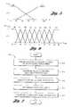
- FIG. 4is a graphical description of a steering angle membership function with labels in accordance with the present invention.
- FIG. 6is a graphical description of a road wheel reference angle membership function with labels in accordance with the present invention.
- FIG. 7is a flow chart of a variable steering ratio control of a vehicle having a steer-by-wire system using fuzzy logic technology in accordance with the present invention.
- FIG. 1illustrates a schematic diagram of a vehicle steer-by-wire system 10 having a steer-by-wire control unit 12 .
- steer-by-wire control unit 12is in electrical communication with steering wheel unit 20 and road wheel assembly unit 23 .
- control unit 12includes a steering wheel controller 14 , a variable steering ratio regulation unit 16 , and a road wheel controller 18 .
- steering wheel controller 14is in electrical communication with road wheel controller 18 by way of variable steering ratio regulation unit 16 .
- the steer-by-wire control unit 12implements steering functions by controlling steering wheel unit 20 and road wheel unit 23 . It is implemented generally by utilizing microprocessors. One or a plurality of microprocessors may be used without falling beyond the scope or spirit of the present invention.
- steer-by-wire system 10includes steering wheel unit 20 having steering wheel 26 mounted to steering shaft 27 .
- Steering wheel unit 20further includes steering wheel sensor 28 mounted to steering shaft 27 or actuator 30 for sensing a steering wheel angle and other variables, e.g., an angular velocity of the steering wheel.
- Steering wheel angleis an angle relative to a center position from which the steering wheel is rotated.
- the steering wheel sensor 28is may be in electrical communication with steering wheel controller 14 which may receive signals indicative of steering wheel angle or angular velocity of the steering wheel.
- road wheel unit 23includes road wheels 31 each connected to a tie rod 33 . Each tie rod 33 is attached to gear assembly 36 .
- Road wheel unit 23further includes road wheel sensor 41 mounted to motor actuator 44 for sensing a road wheel angle. This may include one or a plurality of road wheel sensors. Alternatively, sensor 41 may be mounted to a road wheel tie rod to sense the displacement such that the road wheel angle is obtained. In this embodiment, the sensor 41 is in electrical communication with road wheel controller 18 for sending signals indicative of road wheel angles.
- Road wheel unit 23may also include a motor amplifier 43 for receiving torque control signals from road wheel controller 18 .
- Road wheel unit 23further includes a motor actuator 44 in electrical communication with the motor amplifier 43 . The motor actuator 44 receives motor torque control signal from the amplifier 43 to apply torque on the road wheels 31 .
- the road wheel unit 23includes at least one sensor, amplifier, and actuator for each wheel or both wheels.
- sensors, amplifiers, or actuatorsmay be used for each wheel without falling beyond the scope or spirit of the present invention.
- the steer-by-wire control unit 12further includes a variable steering ratio regulation unit 16 in accordance with the present invention.
- the variable steering ratio unit 16is in electrical communication with steering wheel controller 14 and road wheel controller 18 .
- FIG. 2shows a simplified schematic block diagram for the steer-by-wire system of FIG. 1 .
- variable steering ratio regulation unit 16receives a steering wheel angle signal ⁇ s and a vehicle speed signal V s from steering wheel control system 14 ′ and the vehicle.
- Variable steering ratio regulation unit 16converts steering wheel angle under a scheduling influence of the vehicle speed signal to determine a road wheel reference angle signal ⁇ r-ref which is an input reference signal for the road wheel control system 18 ′.
- the road wheel control systemis designed to have the actual output road wheel angle ⁇ r track the reference angle ⁇ r-ref .
- variable steering ratiosuch as mathematical equations or look-up table.
- the road wheel anglewould turn 1 degree when the steering wheel is turned to 16 degrees in the low speed situation whereas 20 degrees of steering wheel angle rotation would be required to achieve 1 degree of road wheel angle in the high speed situation.
- Fuzzy logic technologyis applied to infer a steering ratio selection in the variable steering ratio regulation unit in this invention.
- the fuzzy logic based variable steering ratio regulation unitdetermines the desired or optional steering ratio.
- the regulation unit 16applies the fuzzy logic inference including a set of fuzzy logic rules to determine a road wheel reference angle from a steering wheel angle and a vehicle speed.
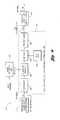
- FIG. 3illustrates a block diagram of the variable steering ratio regulation unit applying fuzzy logic technology in the steer-by-wire system of FIG. 2 .
- the fuzzy logic based applicationsgenerally consists of three elements: fuzzification, inference and defuzzification.
- the variable steering ratio regulation unit 16includes a fuzzification block 46 , an inference block 50 based on fuzzy logic rules block 53 , and a defuzzification block 56 .
- the fuzzification 46converts the exact crisp input steering wheel angle ⁇ s and vehicle speed v s values into values in the fuzzy sets.
- a crisp value of a numerical input variableis labeled with a linguistic term, and the corresponding degree of membership for the input variable is determined.
- labels and membership functions for input variables including the steering wheel angle and vehicle speedwill be defined first.
- the label and membership function for the output road wheel reference angle variableis also described at the same time.
- a membership functionis a data curve that defines how each point in the input crisp values is mapped relative to a membership value (degree of membership) between 0 and 1.
- a degree of membershipis a real number between 0 and 1 such that a transition from membership to non-membership is gradual rather than abrupt. The degree of membership for all its members thus describes a fuzzy set. The higher the number between 0 and 1, the higher the membership.
- a label to a crisp value of a numerical input or output variableis a linguistic term within a membership function which is used to identify each membership. Elements of a membership function are taken from a universe of discourse which is the total possible range for each variable.
- the membership functionmay have other shapes including, but not limited to, trapezoidal, bell curve, and rectangular step shape.
- a vehicle steering wheel angle membership functionhas been plotted depicting a plurality of steering angle labels. As shown, nine triangular shaped curves are defined to cover the required range of an input value (universe of discourse).
- steering wheel angleis labeled with linguistic terms using two-letter abbreviations.
- Nrepresents negative
- Prepresents positive
- ZErepresents approximately zero
- Srepresents small
- Mrepresents medium
- Lrepresents large
- Hrepresents very large.
- labels for the steering wheel angle in the membership function shown in FIG. 4are provided.
- the labels for the steering wheel angle in the membership function and the ranges of steering wheel anglesare provided as follows:
- the vehicle speed membership function with relative labels for each memberis given in FIG. 4 . Low is used to express the low speed and High is used to express high speed.
- the labels for the vehicle speed in the membership function and the range of vehicle speedis given as follows:
- the road wheel reference angle membership function with relative label for each memberis given in FIG. 6 .
- the shapes of membership and labelsare triangular as with that of the steering wheel angle.
- the labels for the road wheel reference angle in the membership function and the range of road wheel reference angleare provided as follows:
- a degree of membership between 0 and 1is determined for each crisp input value within a corresponding membership with relative label.
- Each crisp input valuefalls into at least two memberships expressed by relative labels.
- a crisp steering wheel angle of ⁇ 250°falls within the NL having a degree of membership of 0.5 and the NM having a degree of membership of 0.5.
- the crisp value of ⁇ 250° for the steering wheel angleis converted to 0.5 in the membership expressed with NL and 0.5 in the membership expressed with NM.
- the steering wheel angle of ⁇ 250°belongs to the “negative large” membership at a 50 percent level and belongs to the “negative medium” membership at a 50 percent level.
- a crisp vehicle speed of 40 miles per hourfalls within Low having a degree of membership of 0.25 and High having a degree of membership of 0.75 as shown in FIG. 5 .
- the inference 50infers the fuzzy output variable value by determining the degree of the membership function for the road wheel reference angle.
- the inference processis implemented by using a set of rules 53 .
- rules for the fuzzy inference 50are written that embody a knowledge base required for decision making.
- the rulesmay use several variables both in the condition and the conclusion of the rules.
- the rulesare represented in English as if-then statements. For example: IF Steering Wheel Angle is Positive Small (PS) and Vehicle Speed is Low THEN Road Wheel reference Angle is Positive Small (PS).
- the rulesare defined to cover the different situations encountered in the variable steering ratio from the steering wheel angle to road wheel reference angle.
- the totality of such rulesconstitutes a fuzzy inference unit 50 for the determination of the road wheel reference angle.
- the nine rulesare constructed corresponding to the possible combinations of the steering wheel angle and the vehicle speed. A shorthand method of presenting these nine rules is in Table 4. These rules are usually derived by system requirements and development experience to achieve a desired optimum steering ratio choice.
- the degree of membership function for the output road wheel angleis determined according to the degrees of membership functions for inputs, steering wheel angle and vehicle speed. Since an “AND” operation is used for every rule the minimum criterion of the inputs is used. Therefore, the smaller degree of memberships for inputs steering wheel angle and vehicle speed is chosen to be the degree of membership for the output road wheel reference angle. For example, with a crisp steering angle of ⁇ 250° and vehicle speed of 40 mph mentioned above, a degree of membership of the road wheel reference angle may be determined by using the minimum criterion. In this embodiment, the degree of membership of the output variable are determined as follows:
- Defuzzificationis a process that converts a fuzzy value into a crisp value. This may be accomplished by any suitable method including but not limited to a mean of maximum method, a maximizing decision method, and a Centroidal defuzzification (center of gravity) method.
- the crisp output road wheel angle ⁇ ris determined by means of center of gravity of the area under the membership function curve of the fuzzy output. Moreover, u(x i ) is a degree of membership of x i . Thus, using the center of gravity method, a crisp value of the road wheel reference angle may be determined.
- FIG. 7depicts one flowchart of fuzzy logic based method 400 of controlling variable steering ratio of a vehicle steer-by-wire system.
- Method 400includes sensing an actual steering wheel angle and an actual vehicle speed of the vehicle in box 412 , converting the actual steering wheel angle into values in the fuzzy sets of the steering wheel angle based on a steering wheel membership function with linguistic term labels and determining the corresponding degree of membership of the steering wheel angle in box 414 .
- Method 400further includes converting the actual vehicle speed to a vehicle speed in the fuzzy sets of the vehicle speed based on a vehicle speed membership function with linguistic term labels and determining the corresponding degree of membership of the vehicle speed in box 416 .
- Method 400further includes inferring the fuzzy road wheel reference angel output value by determining the degree of the membership function for the road wheel reference angle using fuzzy rules based on the degrees of steering angle and the vehicle speed in box 418 and converting the fuzzy road wheel angle into an actual road wheel angle in box 420 .
- the inputs to the fuzzy logic based variable steering ratio regulation unit in FIG. 2could include other additional variables to determine a more accurate steering ratio.
- new variables and rulesmay be added to the fuzzy logic inference unit. To accomplish this, a system designer could simply include additional variables and rules to take into account factors that would improve the behavior of the steering ratio control system.
- FIG. 8depicts one embodiment of the variable steering ratio regulation unit in the steer-by-wire system shown of FIG. 1 .
- An adjustable variable steering ratio regulation unit 516 in a steer-by-wire system 512provides a variable steering ratio with adaptive capability for driving types and environmental situations.
- the adjustable variable steering ratio regulation unit 516includes an adjustable factor unit 532 having an adjustable factor a which changes in the range of 0-1. This adjustable factor a is also called the weighting coefficient in the fuzzy logic technology.
- the adjustable factor amay be adjusted based on a driving mode.
- the adjustable factor unit 532receives a mode signal m from a mode generating unit 534 for adjusting the adjustable factor a to proportionally affect a change in the membership functions.
- the output of the fuzzy logic based variable steering ratio regulation unit 516will be adjusted to achieve the objective of adjustable steering ratio.
- a variable mode mis the output of the mode generating unit.
- the mode generating unitcan be designed by using fuzzy logic technology to generate m.
- the mode signal mmay be indicative of a driving mode based on a driving style and an environmental situation.
- the driving stylemay be any suitable driving style including luxury, sport, off-track, inclined, city, highway, and mountainous terrain. Of course, any other suitable driving style may be incorporated therein without falling beyond the scope or spirit of the present invention.
- the environmental situationmay be any suitable environmental situation including dry, wet, icy, and high wind. Of course, any other suitable environmental situation may be incorporated therein without falling beyond the scope or spirit of the present invention.
- the adjustable variable ratiocould be set by the vehicle driver or be set automatically.
- the variable mode mwould be switched to a fixed constant unit such that the adjustable factor a does not vary in value.
- the variable steering ratio fuzzy logic inference unitwill only be affected by the fixed constant setting.
- the mode mwill vary with the driving type and the environmental situation.
- the driving type and the environmental situation selected by the driver or automatic settingmay be incorporated within the steer-by-wire system in accordance with the present invention.
Landscapes
- Engineering & Computer Science (AREA)
- Chemical & Material Sciences (AREA)
- Combustion & Propulsion (AREA)
- Transportation (AREA)
- Mechanical Engineering (AREA)
- Physics & Mathematics (AREA)
- Mathematical Physics (AREA)
- Steering Control In Accordance With Driving Conditions (AREA)
Abstract
Description
| NH: | negative very large | <−300 | deg | ||
| NL: | negative large | −400 to −200 | deg | ||
| NM: | negative medium | −300 to −100 | deg | ||
| NS: | negative small | −200 to 0 | deg | ||
| ZE: | approximately zero | −100 to +100 | deg | ||
| PS: | positive small | 0 to +200 | deg | ||
| PM: | positive medium | +100 to +300 | deg | ||
| PL: | positive large | +200 to +400 | deg | ||
| PH: | positive very large | >+300 | deg. | ||
| Low: low vehicle speed | <60 mph | ||
| High: high vehicle speed | >20 mph. | ||
| NH: | <−24 | deg | ||
| NL: | −32 to −16 | deg | ||
| NM: | −24 to −8 | deg | ||
| NS: | −16 to 0 | deg | ||
| ZE: | −8 to +8 | deg | ||
| PS: | 0 to +16 | deg | ||
| PM: | +8 to +24 | deg | ||
| PL: | +16 to +32 | deg | ||
| PH: | >+24 | deg. | ||
| SW Angle | 0.50 NM | 0.50 NM | 0.50 NL | 0.50 NL |
| Vehicle Speed | 0.25 low | 0.75 high | 0.25 low | 0.75 high |
| RW Ref Angle | 0.25 NM | 0.5 NS | 0.25 NL | 0.5 NM |

Claims (41)
Priority Applications (3)
| Application Number | Priority Date | Filing Date | Title |
|---|---|---|---|
| US10/261,912US6799105B2 (en) | 2002-10-01 | 2002-10-01 | Variable steering ratio control system and method |
| GBGB0320774.3AGB0320774D0 (en) | 2002-10-01 | 2003-09-05 | Variable steering ratio control system and method |
| DE10346146ADE10346146B4 (en) | 2002-10-01 | 2003-10-01 | Method for controlling a variable steering ratio |
Applications Claiming Priority (1)
| Application Number | Priority Date | Filing Date | Title |
|---|---|---|---|
| US10/261,912US6799105B2 (en) | 2002-10-01 | 2002-10-01 | Variable steering ratio control system and method |
Publications (2)
| Publication Number | Publication Date |
|---|---|
| US20040064229A1 US20040064229A1 (en) | 2004-04-01 |
| US6799105B2true US6799105B2 (en) | 2004-09-28 |
Family
ID=29250321
Family Applications (1)
| Application Number | Title | Priority Date | Filing Date |
|---|---|---|---|
| US10/261,912Expired - LifetimeUS6799105B2 (en) | 2002-10-01 | 2002-10-01 | Variable steering ratio control system and method |
Country Status (3)
| Country | Link |
|---|---|
| US (1) | US6799105B2 (en) |
| DE (1) | DE10346146B4 (en) |
| GB (1) | GB0320774D0 (en) |
Cited By (12)
| Publication number | Priority date | Publication date | Assignee | Title |
|---|---|---|---|---|
| US20060289226A1 (en)* | 2005-06-02 | 2006-12-28 | Honda Motor Co., Ltd. | Vehicle steering system for setting steering reaction without using difference between target and actual steering angles |
| US20080195293A1 (en)* | 2007-02-12 | 2008-08-14 | William Robert Norris | Perception model for trajectory following autonomous and human augmented speed control |
| US20080195282A1 (en)* | 2007-02-12 | 2008-08-14 | William Robert Norris | Perception model for trajectory following autonomous and human augmented steering control |
| US20110036660A1 (en)* | 2007-11-19 | 2011-02-17 | Toyota Jidosha Kabushiki Kaisha | Vehicle steering control device |
| US9266552B2 (en) | 2013-08-05 | 2016-02-23 | Rene Guerster | Steering system for wheeled land vehicle |
| US20190230843A1 (en)* | 2018-01-29 | 2019-08-01 | Cnh Industrial America Llc | Harvester With Adjustable Row Dividers |
| US20190389508A1 (en)* | 2018-06-25 | 2019-12-26 | Steering Solutions Ip Holding Corporation | Driver notification using handwheel actuators in steer-by-wire systems |
| US11052940B1 (en) | 2021-03-12 | 2021-07-06 | Canoo Technologies Inc. | Steer-by-wire systems and methods of operating thereof in vehicles |
| US11685427B2 (en) | 2021-04-12 | 2023-06-27 | Toyota Material Handling, Inc. | Electric actuator steering system for forklifts |
| EP4470878A1 (en)* | 2023-05-30 | 2024-12-04 | Hyundai Mobis Co., Ltd. | Apparatus for and method of controlling steer-by-wire system |
| US12371093B2 (en) | 2022-09-28 | 2025-07-29 | Toyota Material Handling, Inc. | Synchronized steering control systems for forklifts |
| US12441392B2 (en) | 2023-05-31 | 2025-10-14 | Toyota Material Handling, Inc. | Electric actuator steering system for forklifts |
Families Citing this family (21)
| Publication number | Priority date | Publication date | Assignee | Title |
|---|---|---|---|---|
| DE102004024545A1 (en)* | 2003-09-05 | 2005-04-07 | Continental Teves Ag & Co. Ohg | Vehicle movement control process has electronic stabilization with steering control comparing actual and ideal conditions and smoothing driver adjustment |
| US7818107B2 (en)* | 2003-11-14 | 2010-10-19 | Continental Teves Ag & Co. Ohg | Method and device for controlling the driving dynamics of a vehicle |
| FR2865989B1 (en)* | 2004-02-06 | 2007-05-11 | Renault Sas | METHOD AND SYSTEM FOR ASSISTING THE STEERING WHEELS OF VEHICLES THUS EQUIPPED |
| US7073622B2 (en) | 2004-06-15 | 2006-07-11 | Ford Global Technologies, Llc | On and off road steering ratios |
| DE102005034936A1 (en)* | 2005-07-27 | 2007-02-08 | Zf Lenksysteme Gmbh | Method for steering element control in motor vehicle steering system, by determining driver's driving behavior based on motor vehicle movement parameters e.g. lateral acceleration |
| CN105074613A (en)* | 2013-01-24 | 2015-11-18 | 汤姆逊许可公司 | Method and system for content discovery |
| US9321458B2 (en)* | 2013-12-17 | 2016-04-26 | Automotive Research & Testing Center | Sliding mode trajectory voting strategy module and driving control system and method thereof |
| DE102015203864B4 (en)* | 2015-03-04 | 2018-05-03 | Ford Global Technologies, Llc | Steering system, motor vehicle with such and method for operating a steering system |
| CN105741637B (en)* | 2016-02-01 | 2019-07-19 | 辽宁工业大学 | Four-wheel hub motor electric vehicle intelligent steering control method |
| US10787174B2 (en)* | 2017-10-13 | 2020-09-29 | Toyota Motor Engineering & Manufacutring North America, Inc. | Automatic vehicle driving mode system |
| DE102018216103B4 (en) | 2018-09-21 | 2021-06-24 | Volkswagen Aktiengesellschaft | Method for operating a control unit of a motor vehicle and motor vehicle with a control unit for carrying out such a method |
| US10915136B2 (en) | 2019-05-07 | 2021-02-09 | Sensata Technologies, Inc. | Dual mode sensing joystick assembly |
| US12122449B2 (en) | 2019-09-06 | 2024-10-22 | Sensata Technologies, Inc. | Steer by wire system with redundant angular position sensing and an end-of-travel stop |
| US11370483B2 (en) | 2020-01-27 | 2022-06-28 | Sensata Technologies, Inc. | Steer by wire system with dynamic braking and endstop cushioning for haptic feel |
| US11447175B2 (en)* | 2020-05-31 | 2022-09-20 | Steering Solutions Ip Holding Corporation | Steer ratio synchronization for steer-by-wire systems |
| JP7489021B2 (en)* | 2020-08-31 | 2024-05-23 | 株式会社ジェイテクト | Steering gear |
| CN112519593A (en)* | 2020-12-10 | 2021-03-19 | 哈工大机器人湖州国际创新研究院 | Control method and device suitable for four-wheel omnidirectional electric vehicle |
| CN112622645B (en)* | 2021-03-09 | 2021-06-01 | 成都微精电机股份公司 | Self-adjusting method for fully-automatic control motor of vehicle |
| CN113504726A (en)* | 2021-07-13 | 2021-10-15 | 中国石油大学(华东) | Intelligent automobile track tracking control method fused with backstepping method |
| CN113895518B (en)* | 2021-10-29 | 2022-11-18 | 上海集度汽车有限公司 | Vehicle Steering Ratio Adjustment Method, Device and Storage Medium |
| CN115512339A (en)* | 2022-09-29 | 2022-12-23 | 苏州轻棹科技有限公司 | Online identification method for steering ratio of steering wheel |
Citations (15)
| Publication number | Priority date | Publication date | Assignee | Title |
|---|---|---|---|---|
| US4930084A (en) | 1987-05-19 | 1990-05-29 | Honda Giken Kogyo Kabushiki Kaisha | Vehicle control system |
| US5101351A (en)* | 1989-04-12 | 1992-03-31 | Nissan Motor Company, Limited | Autonomous vehicle using fuzzy control |
| US5180214A (en) | 1991-12-30 | 1993-01-19 | National Science Council | Servo-type phase-locked loop anti-skid brake control system |
| US5218542A (en)* | 1990-03-30 | 1993-06-08 | Shinko Electric Co., Ltd. | Control system for unmanned carrier vehicle |
| EP0638742A1 (en)* | 1993-08-12 | 1995-02-15 | Siemens Aktiengesellschaft | Control system for vehicles, in particular for automatic transmissions |
| US5519614A (en)* | 1992-09-22 | 1996-05-21 | Mitsubishi Jidosha Kogyo Kabushiki Kaisha | Electronically controlled power steering apparatus and method therefor |
| US5545960A (en)* | 1991-04-09 | 1996-08-13 | International Business Machines Corporation | Autonomous mobile machine, and system and method for controlling a mobile machine |
| US5561603A (en)* | 1992-01-29 | 1996-10-01 | Toyota Jidosha Kabushiki Kaisha | Vehicle rear wheel steering angle controlling apparatus having means for reducing vehicle-speed-based change in the angle, when steering wheel is not operated |
| US5634698A (en)* | 1994-02-19 | 1997-06-03 | Robert Bosch Gmbh | System for controlling brake pressure based on fuzzy logic using steering angle and yaw speed |
| FR2787081A1 (en)* | 1998-12-09 | 2000-06-16 | Renault | Fuzzy logic system for determining the actions and intentions of the driver on the vehicle steering wheel, measures the couple exerted on the steering wheel |
| US6370460B1 (en) | 1999-09-17 | 2002-04-09 | Delphi Technologies, Inc. | Steer-by-wire system |
| US20020106108A1 (en)* | 2001-02-02 | 2002-08-08 | The Board Of Trustees Of The University | Method and apparatus for automatically steering a vehicle in an agricultural field using a plurality of fuzzy logic membership functions |
| US20020105428A1 (en)* | 2001-02-02 | 2002-08-08 | The Board Of Trustees Of The University Of Illinois | Fuzzy logic method for adaptively evaluating the validity of sensor data |
| US6442463B1 (en)* | 2001-02-09 | 2002-08-27 | The Board Of Trustees Of The University Of Illinois | Fuzzy steering controller |
| US6487501B1 (en)* | 2001-06-12 | 2002-11-26 | Hyundai Motor Company | System for preventing lane deviation of vehicle and control method thereof |
Family Cites Families (2)
| Publication number | Priority date | Publication date | Assignee | Title |
|---|---|---|---|---|
| JP2803487B2 (en)* | 1992-09-22 | 1998-09-24 | 三菱自動車工業株式会社 | Fuzzy control type electronic control power steering device |
| JP2950096B2 (en)* | 1993-06-01 | 1999-09-20 | 三菱自動車工業株式会社 | Electronically controlled power steering device |
- 2002
- 2002-10-01USUS10/261,912patent/US6799105B2/ennot_activeExpired - Lifetime
- 2003
- 2003-09-05GBGBGB0320774.3Apatent/GB0320774D0/ennot_activeCeased
- 2003-10-01DEDE10346146Apatent/DE10346146B4/ennot_activeExpired - Fee Related
Patent Citations (15)
| Publication number | Priority date | Publication date | Assignee | Title |
|---|---|---|---|---|
| US4930084A (en) | 1987-05-19 | 1990-05-29 | Honda Giken Kogyo Kabushiki Kaisha | Vehicle control system |
| US5101351A (en)* | 1989-04-12 | 1992-03-31 | Nissan Motor Company, Limited | Autonomous vehicle using fuzzy control |
| US5218542A (en)* | 1990-03-30 | 1993-06-08 | Shinko Electric Co., Ltd. | Control system for unmanned carrier vehicle |
| US5545960A (en)* | 1991-04-09 | 1996-08-13 | International Business Machines Corporation | Autonomous mobile machine, and system and method for controlling a mobile machine |
| US5180214A (en) | 1991-12-30 | 1993-01-19 | National Science Council | Servo-type phase-locked loop anti-skid brake control system |
| US5561603A (en)* | 1992-01-29 | 1996-10-01 | Toyota Jidosha Kabushiki Kaisha | Vehicle rear wheel steering angle controlling apparatus having means for reducing vehicle-speed-based change in the angle, when steering wheel is not operated |
| US5519614A (en)* | 1992-09-22 | 1996-05-21 | Mitsubishi Jidosha Kogyo Kabushiki Kaisha | Electronically controlled power steering apparatus and method therefor |
| EP0638742A1 (en)* | 1993-08-12 | 1995-02-15 | Siemens Aktiengesellschaft | Control system for vehicles, in particular for automatic transmissions |
| US5634698A (en)* | 1994-02-19 | 1997-06-03 | Robert Bosch Gmbh | System for controlling brake pressure based on fuzzy logic using steering angle and yaw speed |
| FR2787081A1 (en)* | 1998-12-09 | 2000-06-16 | Renault | Fuzzy logic system for determining the actions and intentions of the driver on the vehicle steering wheel, measures the couple exerted on the steering wheel |
| US6370460B1 (en) | 1999-09-17 | 2002-04-09 | Delphi Technologies, Inc. | Steer-by-wire system |
| US20020106108A1 (en)* | 2001-02-02 | 2002-08-08 | The Board Of Trustees Of The University | Method and apparatus for automatically steering a vehicle in an agricultural field using a plurality of fuzzy logic membership functions |
| US20020105428A1 (en)* | 2001-02-02 | 2002-08-08 | The Board Of Trustees Of The University Of Illinois | Fuzzy logic method for adaptively evaluating the validity of sensor data |
| US6442463B1 (en)* | 2001-02-09 | 2002-08-27 | The Board Of Trustees Of The University Of Illinois | Fuzzy steering controller |
| US6487501B1 (en)* | 2001-06-12 | 2002-11-26 | Hyundai Motor Company | System for preventing lane deviation of vehicle and control method thereof |
Cited By (27)
| Publication number | Priority date | Publication date | Assignee | Title |
|---|---|---|---|---|
| US7529605B2 (en) | 2005-06-02 | 2009-05-05 | Honda Motor Co., Ltd. | Vehicle steering system for setting steering reaction without using difference between target and actual steering angles |
| US20060289226A1 (en)* | 2005-06-02 | 2006-12-28 | Honda Motor Co., Ltd. | Vehicle steering system for setting steering reaction without using difference between target and actual steering angles |
| US20120271517A1 (en)* | 2007-02-12 | 2012-10-25 | Deere & Company | Perception Model for Trajectory Following Autonomous and Human Augmented Steering Control |
| US20080195282A1 (en)* | 2007-02-12 | 2008-08-14 | William Robert Norris | Perception model for trajectory following autonomous and human augmented steering control |
| US8195364B2 (en)* | 2007-02-12 | 2012-06-05 | Deere & Company | Perception model for trajectory following autonomous and human augmented steering control |
| US8498796B2 (en) | 2007-02-12 | 2013-07-30 | Deere & Company | Perception model for trajectory following autonomous and human augmented speed control |
| US8510034B2 (en)* | 2007-02-12 | 2013-08-13 | Deere & Company | Perception model for trajectory following autonomous and human augmented steering control |
| US20080195293A1 (en)* | 2007-02-12 | 2008-08-14 | William Robert Norris | Perception model for trajectory following autonomous and human augmented speed control |
| US20110036660A1 (en)* | 2007-11-19 | 2011-02-17 | Toyota Jidosha Kabushiki Kaisha | Vehicle steering control device |
| US8511420B2 (en)* | 2007-11-19 | 2013-08-20 | Toyota Jidosha Kabushiki Kaisha | Vehicle steering control device |
| US9266552B2 (en) | 2013-08-05 | 2016-02-23 | Rene Guerster | Steering system for wheeled land vehicle |
| US10674652B2 (en)* | 2018-01-29 | 2020-06-09 | Cnh Industrial America Llc | Harvester with adjustable row dividers |
| US20190230843A1 (en)* | 2018-01-29 | 2019-08-01 | Cnh Industrial America Llc | Harvester With Adjustable Row Dividers |
| US20190389508A1 (en)* | 2018-06-25 | 2019-12-26 | Steering Solutions Ip Holding Corporation | Driver notification using handwheel actuators in steer-by-wire systems |
| US10676129B2 (en)* | 2018-06-25 | 2020-06-09 | Steering Solutions Ip Holding Corporation | Driver notification using handwheel actuators in steer-by-wire systems |
| US11834110B2 (en) | 2021-03-12 | 2023-12-05 | Canoo Technologies Inc. | Steer-by-wire systems and methods of operating thereof in vehicles |
| US11465675B2 (en) | 2021-03-12 | 2022-10-11 | Canoo Technologies Inc. | Steer-by-wire systems and methods of operating thereof in vehicles |
| US11479293B2 (en) | 2021-03-12 | 2022-10-25 | Canoo Technologies Inc. | Steer-by-wire systems and methods of operating thereof in vehicles |
| US11492039B2 (en) | 2021-03-12 | 2022-11-08 | Canoo Technologies Inc. | Steer-by-wire systems and methods of operating thereof in vehicles |
| US11492040B2 (en) | 2021-03-12 | 2022-11-08 | Canoo Technologies Inc. | Steer-by-wire systems and methods of operating thereof in vehicles |
| US11738800B2 (en) | 2021-03-12 | 2023-08-29 | Canoo Technologies Inc. | Steer-by-wire systems and methods of operating thereof in vehicles |
| US11814117B2 (en) | 2021-03-12 | 2023-11-14 | Canoo Technologies Inc. | Steer-by-wire systems and methods of operating thereof in vehicles |
| US11052940B1 (en) | 2021-03-12 | 2021-07-06 | Canoo Technologies Inc. | Steer-by-wire systems and methods of operating thereof in vehicles |
| US11685427B2 (en) | 2021-04-12 | 2023-06-27 | Toyota Material Handling, Inc. | Electric actuator steering system for forklifts |
| US12371093B2 (en) | 2022-09-28 | 2025-07-29 | Toyota Material Handling, Inc. | Synchronized steering control systems for forklifts |
| EP4470878A1 (en)* | 2023-05-30 | 2024-12-04 | Hyundai Mobis Co., Ltd. | Apparatus for and method of controlling steer-by-wire system |
| US12441392B2 (en) | 2023-05-31 | 2025-10-14 | Toyota Material Handling, Inc. | Electric actuator steering system for forklifts |
Also Published As
| Publication number | Publication date |
|---|---|
| DE10346146A1 (en) | 2004-05-06 |
| US20040064229A1 (en) | 2004-04-01 |
| GB0320774D0 (en) | 2003-10-08 |
| DE10346146B4 (en) | 2009-07-23 |
Similar Documents
| Publication | Publication Date | Title |
|---|---|---|
| US6799105B2 (en) | Variable steering ratio control system and method | |
| US6795763B2 (en) | Expert-type vehicle steering control system and method | |
| CN114655248B (en) | Transverse control method and device for automatic driving vehicle and vehicle | |
| US8160795B2 (en) | Drive power control apparatus and method for vehicle | |
| US6282472B1 (en) | Electric power steering system with boost curve having portions defined by polynomial equations | |
| US6640171B2 (en) | Motor vehicle with supplemental rear steering having open and closed loop modes | |
| US4905783A (en) | Vehicular controller with differential wheel speed input | |
| US6377884B1 (en) | Method and device for controlling the drive train of a vehicle | |
| US7318629B1 (en) | Steer by brake control system | |
| US20070192005A1 (en) | Control device for electrical power steering system | |
| US6442463B1 (en) | Fuzzy steering controller | |
| JP2002178943A (en) | Lane keep assist control device | |
| CN111959506B (en) | Vehicle and control method and device for vehicle formation running | |
| CN111098917B (en) | Control method of electric power steering | |
| CN114228690A (en) | Automatic driving vehicle roll control method based on DDPG and iterative control | |
| US6643573B2 (en) | Method for automatically adjusting reference models in vehicle stability enhancement (VSE) systems | |
| EP0982220B1 (en) | Propulsion motor control apparatus for battery vehicle | |
| Smith et al. | Nonlinear-gain-optimised controller development and evaluation for automated emergency vehicle steering | |
| JP2008197848A (en) | Fuzzy control device, lane travel support device, and steering assist device | |
| JPS62149558A (en) | Steering force control device for power steering device | |
| CN113276835A (en) | Vehicle steering stability control method and device, ESC and vehicle | |
| US7689392B2 (en) | Method and apparatus for controlling a vehicle computer model | |
| CN117048639A (en) | Vehicle self-adaptive path control method, storage medium and computer | |
| JPH0999853A (en) | Front and rear wheel steering system | |
| US20250058826A1 (en) | Method for ascertaining a controller steering torque to be predefined for a steering actuator of a motor vehicle |
Legal Events
| Date | Code | Title | Description |
|---|---|---|---|
| AS | Assignment | Owner name:VISTEON GLOBAL TECHNOLOGIES, INC., MICHIGAN Free format text:ASSIGNMENT OF ASSIGNORS INTEREST;ASSIGNORS:STOUT, GREGORY J.;YAO, YIXIN;REEL/FRAME:013361/0184 Effective date:20020927 | |
| STCF | Information on status: patent grant | Free format text:PATENTED CASE | |
| FPAY | Fee payment | Year of fee payment:4 | |
| AS | Assignment | Owner name:JPMORGAN CHASE BANK, N.A., AS ADMINISTRATIVE AGENT Free format text:SECURITY AGREEMENT;ASSIGNOR:VISTEON GLOBAL TECHNOLOGIES, INC.;REEL/FRAME:020497/0733 Effective date:20060613 | |
| AS | Assignment | Owner name:JPMORGAN CHASE BANK, TEXAS Free format text:SECURITY INTEREST;ASSIGNOR:VISTEON GLOBAL TECHNOLOGIES, INC.;REEL/FRAME:022368/0001 Effective date:20060814 Owner name:JPMORGAN CHASE BANK,TEXAS Free format text:SECURITY INTEREST;ASSIGNOR:VISTEON GLOBAL TECHNOLOGIES, INC.;REEL/FRAME:022368/0001 Effective date:20060814 | |
| AS | Assignment | Owner name:WILMINGTON TRUST FSB, AS ADMINISTRATIVE AGENT, MIN Free format text:ASSIGNMENT OF SECURITY INTEREST IN PATENTS;ASSIGNOR:JPMORGAN CHASE BANK, N.A., AS ADMINISTRATIVE AGENT;REEL/FRAME:022575/0186 Effective date:20090415 Owner name:WILMINGTON TRUST FSB, AS ADMINISTRATIVE AGENT,MINN Free format text:ASSIGNMENT OF SECURITY INTEREST IN PATENTS;ASSIGNOR:JPMORGAN CHASE BANK, N.A., AS ADMINISTRATIVE AGENT;REEL/FRAME:022575/0186 Effective date:20090415 | |
| AS | Assignment | Owner name:THE BANK OF NEW YORK MELLON, AS ADMINISTRATIVE AGE Free format text:ASSIGNMENT OF PATENT SECURITY INTEREST;ASSIGNOR:JPMORGAN CHASE BANK, N.A., A NATIONAL BANKING ASSOCIATION;REEL/FRAME:022974/0057 Effective date:20090715 | |
| AS | Assignment | Owner name:VISTEON GLOBAL TECHNOLOGIES, INC., MICHIGAN Free format text:RELEASE BY SECURED PARTY AGAINST SECURITY INTEREST IN PATENTS RECORDED AT REEL 022974 FRAME 0057;ASSIGNOR:THE BANK OF NEW YORK MELLON;REEL/FRAME:025095/0711 Effective date:20101001 | |
| AS | Assignment | Owner name:VISTEON GLOBAL TECHNOLOGIES, INC., MICHIGAN Free format text:RELEASE BY SECURED PARTY AGAINST SECURITY INTEREST IN PATENTS RECORDED AT REEL 022575 FRAME 0186;ASSIGNOR:WILMINGTON TRUST FSB, AS ADMINISTRATIVE AGENT;REEL/FRAME:025105/0201 Effective date:20101001 | |
| AS | Assignment | Owner name:MORGAN STANLEY SENIOR FUNDING, INC., AS AGENT, NEW Free format text:SECURITY AGREEMENT (REVOLVER);ASSIGNORS:VISTEON CORPORATION;VC AVIATION SERVICES, LLC;VISTEON ELECTRONICS CORPORATION;AND OTHERS;REEL/FRAME:025238/0298 Effective date:20101001 Owner name:MORGAN STANLEY SENIOR FUNDING, INC., AS AGENT, NEW Free format text:SECURITY AGREEMENT;ASSIGNORS:VISTEON CORPORATION;VC AVIATION SERVICES, LLC;VISTEON ELECTRONICS CORPORATION;AND OTHERS;REEL/FRAME:025241/0317 Effective date:20101007 | |
| AS | Assignment | Owner name:VISTEON GLOBAL TREASURY, INC., MICHIGAN Free format text:RELEASE BY SECURED PARTY AGAINST SECURITY INTEREST IN PATENTS ON REEL 025241 FRAME 0317;ASSIGNOR:MORGAN STANLEY SENIOR FUNDING, INC.;REEL/FRAME:026178/0412 Effective date:20110406 Owner name:VISTEON CORPORATION, MICHIGAN Free format text:RELEASE BY SECURED PARTY AGAINST SECURITY INTEREST IN PATENTS ON REEL 025241 FRAME 0317;ASSIGNOR:MORGAN STANLEY SENIOR FUNDING, INC.;REEL/FRAME:026178/0412 Effective date:20110406 Owner name:VISTEON INTERNATIONAL HOLDINGS, INC., MICHIGAN Free format text:RELEASE BY SECURED PARTY AGAINST SECURITY INTEREST IN PATENTS ON REEL 025241 FRAME 0317;ASSIGNOR:MORGAN STANLEY SENIOR FUNDING, INC.;REEL/FRAME:026178/0412 Effective date:20110406 Owner name:VISTEON GLOBAL TECHNOLOGIES, INC., MICHIGAN Free format text:RELEASE BY SECURED PARTY AGAINST SECURITY INTEREST IN PATENTS ON REEL 025241 FRAME 0317;ASSIGNOR:MORGAN STANLEY SENIOR FUNDING, INC.;REEL/FRAME:026178/0412 Effective date:20110406 Owner name:VISTEON SYSTEMS, LLC, MICHIGAN Free format text:RELEASE BY SECURED PARTY AGAINST SECURITY INTEREST IN PATENTS ON REEL 025241 FRAME 0317;ASSIGNOR:MORGAN STANLEY SENIOR FUNDING, INC.;REEL/FRAME:026178/0412 Effective date:20110406 Owner name:VISTEON INTERNATIONAL BUSINESS DEVELOPMENT, INC., Free format text:RELEASE BY SECURED PARTY AGAINST SECURITY INTEREST IN PATENTS ON REEL 025241 FRAME 0317;ASSIGNOR:MORGAN STANLEY SENIOR FUNDING, INC.;REEL/FRAME:026178/0412 Effective date:20110406 Owner name:VC AVIATION SERVICES, LLC, MICHIGAN Free format text:RELEASE BY SECURED PARTY AGAINST SECURITY INTEREST IN PATENTS ON REEL 025241 FRAME 0317;ASSIGNOR:MORGAN STANLEY SENIOR FUNDING, INC.;REEL/FRAME:026178/0412 Effective date:20110406 Owner name:VISTEON ELECTRONICS CORPORATION, MICHIGAN Free format text:RELEASE BY SECURED PARTY AGAINST SECURITY INTEREST IN PATENTS ON REEL 025241 FRAME 0317;ASSIGNOR:MORGAN STANLEY SENIOR FUNDING, INC.;REEL/FRAME:026178/0412 Effective date:20110406 Owner name:VISTEON EUROPEAN HOLDING, INC., MICHIGAN Free format text:RELEASE BY SECURED PARTY AGAINST SECURITY INTEREST IN PATENTS ON REEL 025241 FRAME 0317;ASSIGNOR:MORGAN STANLEY SENIOR FUNDING, INC.;REEL/FRAME:026178/0412 Effective date:20110406 | |
| FPAY | Fee payment | Year of fee payment:8 | |
| AS | Assignment | Owner name:VISTEON GLOBAL TECHNOLOGIES, INC., MICHIGAN Free format text:PARTIAL RELEASE OF PATENTS REFLECTED ON SCHEDULE 1 OF THE PATENT RELEASE;ASSIGNOR:MORGAN STANLEY SENIOR FUNDING, INC., AS AGENT;REEL/FRAME:029341/0312 Effective date:20121109 Owner name:VISTEON INTERNATIONAL HOLDINGS, INC., MICHIGAN Free format text:PARTIAL RELEASE OF PATENTS REFLECTED ON SCHEDULE 1 OF THE PATENT RELEASE;ASSIGNOR:MORGAN STANLEY SENIOR FUNDING, INC., AS AGENT;REEL/FRAME:029341/0312 Effective date:20121109 Owner name:VISTEON CORPORATION, MICHIGAN Free format text:PARTIAL RELEASE OF PATENTS REFLECTED ON SCHEDULE 1 OF THE PATENT RELEASE;ASSIGNOR:MORGAN STANLEY SENIOR FUNDING, INC., AS AGENT;REEL/FRAME:029341/0312 Effective date:20121109 Owner name:VISTEON EUROPEAN HOLDINGS, INC., MICHIGAN Free format text:PARTIAL RELEASE OF PATENTS REFLECTED ON SCHEDULE 1 OF THE PATENT RELEASE;ASSIGNOR:MORGAN STANLEY SENIOR FUNDING, INC., AS AGENT;REEL/FRAME:029341/0312 Effective date:20121109 Owner name:VISTEON SYSTEMS, LLC, MICHIGAN Free format text:PARTIAL RELEASE OF PATENTS REFLECTED ON SCHEDULE 1 OF THE PATENT RELEASE;ASSIGNOR:MORGAN STANLEY SENIOR FUNDING, INC., AS AGENT;REEL/FRAME:029341/0312 Effective date:20121109 Owner name:VISTEON INTERNATIONAL BUSINESS DEVELOPMENT, INC., Free format text:PARTIAL RELEASE OF PATENTS REFLECTED ON SCHEDULE 1 OF THE PATENT RELEASE;ASSIGNOR:MORGAN STANLEY SENIOR FUNDING, INC., AS AGENT;REEL/FRAME:029341/0312 Effective date:20121109 Owner name:VISTEON GLOBAL TREASURY, INC., MICHIGAN Free format text:PARTIAL RELEASE OF PATENTS REFLECTED ON SCHEDULE 1 OF THE PATENT RELEASE;ASSIGNOR:MORGAN STANLEY SENIOR FUNDING, INC., AS AGENT;REEL/FRAME:029341/0312 Effective date:20121109 Owner name:VC AVIATION SERVICES, LLC, MICHIGAN Free format text:PARTIAL RELEASE OF PATENTS REFLECTED ON SCHEDULE 1 OF THE PATENT RELEASE;ASSIGNOR:MORGAN STANLEY SENIOR FUNDING, INC., AS AGENT;REEL/FRAME:029341/0312 Effective date:20121109 Owner name:VISTEON ELECTRONICS CORPORATION, MICHIGAN Free format text:PARTIAL RELEASE OF PATENTS REFLECTED ON SCHEDULE 1 OF THE PATENT RELEASE;ASSIGNOR:MORGAN STANLEY SENIOR FUNDING, INC., AS AGENT;REEL/FRAME:029341/0312 Effective date:20121109 | |
| FEPP | Fee payment procedure | Free format text:PAYOR NUMBER ASSIGNED (ORIGINAL EVENT CODE: ASPN); ENTITY STATUS OF PATENT OWNER: LARGE ENTITY | |
| AS | Assignment | Owner name:NISSAN MOTOR CO., LTD., JAPAN Free format text:ASSIGNMENT OF ASSIGNORS INTEREST;ASSIGNOR:VISTEON GLOBAL TECHNOLOGIES, INC.;REEL/FRAME:030115/0904 Effective date:20121107 | |
| AS | Assignment | Owner name:VISTEON INTERNATIONAL HOLDINGS, INC., MICHIGAN Free format text:RELEASE OF SECURITY INTEREST IN INTELLECTUAL PROPERTY;ASSIGNOR:MORGAN STANLEY SENIOR FUNDING, INC.;REEL/FRAME:033107/0717 Effective date:20140409 Owner name:VISTEON ELECTRONICS CORPORATION, MICHIGAN Free format text:RELEASE OF SECURITY INTEREST IN INTELLECTUAL PROPERTY;ASSIGNOR:MORGAN STANLEY SENIOR FUNDING, INC.;REEL/FRAME:033107/0717 Effective date:20140409 Owner name:VISTEON CORPORATION, MICHIGAN Free format text:RELEASE OF SECURITY INTEREST IN INTELLECTUAL PROPERTY;ASSIGNOR:MORGAN STANLEY SENIOR FUNDING, INC.;REEL/FRAME:033107/0717 Effective date:20140409 Owner name:VISTEON INTERNATIONAL BUSINESS DEVELOPMENT, INC., Free format text:RELEASE OF SECURITY INTEREST IN INTELLECTUAL PROPERTY;ASSIGNOR:MORGAN STANLEY SENIOR FUNDING, INC.;REEL/FRAME:033107/0717 Effective date:20140409 Owner name:VISTEON GLOBAL TREASURY, INC., MICHIGAN Free format text:RELEASE OF SECURITY INTEREST IN INTELLECTUAL PROPERTY;ASSIGNOR:MORGAN STANLEY SENIOR FUNDING, INC.;REEL/FRAME:033107/0717 Effective date:20140409 Owner name:VISTEON SYSTEMS, LLC, MICHIGAN Free format text:RELEASE OF SECURITY INTEREST IN INTELLECTUAL PROPERTY;ASSIGNOR:MORGAN STANLEY SENIOR FUNDING, INC.;REEL/FRAME:033107/0717 Effective date:20140409 Owner name:VC AVIATION SERVICES, LLC, MICHIGAN Free format text:RELEASE OF SECURITY INTEREST IN INTELLECTUAL PROPERTY;ASSIGNOR:MORGAN STANLEY SENIOR FUNDING, INC.;REEL/FRAME:033107/0717 Effective date:20140409 Owner name:VISTEON EUROPEAN HOLDINGS, INC., MICHIGAN Free format text:RELEASE OF SECURITY INTEREST IN INTELLECTUAL PROPERTY;ASSIGNOR:MORGAN STANLEY SENIOR FUNDING, INC.;REEL/FRAME:033107/0717 Effective date:20140409 Owner name:VISTEON GLOBAL TECHNOLOGIES, INC., MICHIGAN Free format text:RELEASE OF SECURITY INTEREST IN INTELLECTUAL PROPERTY;ASSIGNOR:MORGAN STANLEY SENIOR FUNDING, INC.;REEL/FRAME:033107/0717 Effective date:20140409 | |
| FPAY | Fee payment | Year of fee payment:12 |