US6799099B2 - Material handling systems with high frequency radio location devices - Google Patents
Material handling systems with high frequency radio location devicesDownload PDFInfo
- Publication number
- US6799099B2 US6799099B2US10/209,766US20976602AUS6799099B2US 6799099 B2US6799099 B2US 6799099B2US 20976602 AUS20976602 AUS 20976602AUS 6799099 B2US6799099 B2US 6799099B2
- Authority
- US
- United States
- Prior art keywords
- beacons
- vehicle
- mobile
- stationary
- electromagnetic energy
- Prior art date
- Legal status (The legal status is an assumption and is not a legal conclusion. Google has not performed a legal analysis and makes no representation as to the accuracy of the status listed.)
- Expired - Fee Related
Links
- 239000000463materialSubstances0.000titleclaimsabstractdescription46
- 238000000034methodMethods0.000claimsdescription43
- 238000004891communicationMethods0.000claimsdescription42
- 238000005259measurementMethods0.000claimsdescription42
- 230000005540biological transmissionEffects0.000claimsdescription9
- 230000037361pathwayEffects0.000claimsdescription8
- 230000008859changeEffects0.000claimsdescription3
- 230000004044responseEffects0.000claimsdescription2
- 230000033001locomotionEffects0.000description15
- 238000004364calculation methodMethods0.000description11
- 238000009434installationMethods0.000description10
- 238000012544monitoring processMethods0.000description7
- 238000001514detection methodMethods0.000description6
- 238000012935AveragingMethods0.000description5
- 230000006870functionEffects0.000description5
- 230000000737periodic effectEffects0.000description3
- 230000000903blocking effectEffects0.000description2
- 238000010276constructionMethods0.000description2
- 230000001419dependent effectEffects0.000description2
- 230000010006flightEffects0.000description2
- 238000012806monitoring deviceMethods0.000description2
- 230000003287optical effectEffects0.000description2
- 230000008569processEffects0.000description2
- 230000001360synchronised effectEffects0.000description2
- 238000011144upstream manufacturingMethods0.000description2
- 230000000007visual effectEffects0.000description2
- 238000004458analytical methodMethods0.000description1
- 230000003190augmentative effectEffects0.000description1
- 230000008901benefitEffects0.000description1
- 238000010586diagramMethods0.000description1
- 238000005553drillingMethods0.000description1
- 238000005516engineering processMethods0.000description1
- 230000004907fluxEffects0.000description1
- 230000006872improvementEffects0.000description1
- 230000006698inductionEffects0.000description1
- 230000000977initiatory effectEffects0.000description1
- 238000004519manufacturing processMethods0.000description1
- 230000007246mechanismEffects0.000description1
- 239000002184metalSubstances0.000description1
- 238000012986modificationMethods0.000description1
- 230000004048modificationEffects0.000description1
- 238000003825pressingMethods0.000description1
- 238000012545processingMethods0.000description1
- 230000005855radiationEffects0.000description1
- 230000008054signal transmissionEffects0.000description1
- 238000003860storageMethods0.000description1
- 239000013589supplementSubstances0.000description1
- 238000012546transferMethods0.000description1
Images


Classifications
- G—PHYSICS
- G01—MEASURING; TESTING
- G01S—RADIO DIRECTION-FINDING; RADIO NAVIGATION; DETERMINING DISTANCE OR VELOCITY BY USE OF RADIO WAVES; LOCATING OR PRESENCE-DETECTING BY USE OF THE REFLECTION OR RERADIATION OF RADIO WAVES; ANALOGOUS ARRANGEMENTS USING OTHER WAVES
- G01S5/00—Position-fixing by co-ordinating two or more direction or position line determinations; Position-fixing by co-ordinating two or more distance determinations
- G01S5/02—Position-fixing by co-ordinating two or more direction or position line determinations; Position-fixing by co-ordinating two or more distance determinations using radio waves
- G01S5/14—Determining absolute distances from a plurality of spaced points of known location
- G—PHYSICS
- G05—CONTROLLING; REGULATING
- G05D—SYSTEMS FOR CONTROLLING OR REGULATING NON-ELECTRIC VARIABLES
- G05D1/00—Control of position, course, altitude or attitude of land, water, air or space vehicles, e.g. using automatic pilots
- G05D1/02—Control of position or course in two dimensions
- G05D1/021—Control of position or course in two dimensions specially adapted to land vehicles
- G05D1/0276—Control of position or course in two dimensions specially adapted to land vehicles using signals provided by a source external to the vehicle
- G05D1/028—Control of position or course in two dimensions specially adapted to land vehicles using signals provided by a source external to the vehicle using a RF signal
- G05D1/0282—Control of position or course in two dimensions specially adapted to land vehicles using signals provided by a source external to the vehicle using a RF signal generated in a local control room
- G—PHYSICS
- G01—MEASURING; TESTING
- G01S—RADIO DIRECTION-FINDING; RADIO NAVIGATION; DETERMINING DISTANCE OR VELOCITY BY USE OF RADIO WAVES; LOCATING OR PRESENCE-DETECTING BY USE OF THE REFLECTION OR RERADIATION OF RADIO WAVES; ANALOGOUS ARRANGEMENTS USING OTHER WAVES
- G01S5/00—Position-fixing by co-ordinating two or more direction or position line determinations; Position-fixing by co-ordinating two or more distance determinations
- G01S5/02—Position-fixing by co-ordinating two or more direction or position line determinations; Position-fixing by co-ordinating two or more distance determinations using radio waves
- G01S5/0247—Determining attitude
Definitions
- This inventionrelates generally to material handling systems, including sortation systems, monorail systems and the like and more particularly to navigation and/or communication systems for material handling systems.
- AGVsAutomatic guided vehicles, or AGVs for short, are used extensively today in a wide variety of material handling applications.
- AGVscome in a wide variety of types, from those that carry cargo on their back, to those that tow trains of cargo behind them on carts, to still other types.
- the determination of the vehicle's positionhas been carried out in several different ways.
- Some AGVsuse laser targets positioned at known locations throughout the factory to reflect a laser beam emitted from the AGV. The reflection of the laser beams are detected by the AGV and used to determine the position of the AGV relative to the targets. Using three or more targets, the vehicle can then calculate its position.
- An example of such a prior art AGV systemis disclosed in U.S. Pat. No. 4,790,402 issued to Field et al., the disclosure of which is hereby incorporated herein by reference.
- the vehicleuses a combination of incremental sensors and one or more beacon sensors to determine its position.
- the incremental sensorsdetect changes in the vehicle's position or bearing, while the beacon sensors make absolute measurements of the vehicle's position or heading with respect to one or more fixed beacons positioned throughout the factory.
- the vehicleis able to determine its position and/or heading sufficiently often and with sufficient accuracy to guide itself to its intended destination.
- Examples of incremental sensors used on AGVsinclude wheel encoders that measure the rotations of one or more wheels on the AGV, and gyroscopes that measure changes in the vehicle's orientation.
- beaconsinclude magnets buried in the floor, transponders positioned at known locations, laser targets such as those described above, and various other detectable marks or objects.
- AGV systemthat uses wheel encoders, a gyro, and magnets positioned in the floor for navigation is disclosed in U.S. Pat. No. 5,281,901 issued to Yardley et al., the disclosure of which is hereby incorporated herein by reference.
- prior art AGV systemshave also had certain disadvantages in their communications systems.
- some prior art AGV systemsrely on a central controller or repeater that issues or repeats communications received from vehicles. In such systems, the vehicles do not directly contact each other, but instead channel their messages to the central controller or repeater. If a communications failure occurs with the central controller or repeater, then the whole communications system fails. Such single point of failure communication systems are desirably avoided, if possible.
- prior art AGV systemshave often used RF communications which are susceptible to interference, especially in plants that have extensive metal structures and electrical/electronic equipment that may emit its own radiation. These problems are also desirably avoided. The need can therefore be seen for an AGV system which overcomes the aforementioned disadvantages.
- Prior AGVshave also typically included one or more bumpers on their front and/or back ends that allow the vehicle to safely stop or slow down when objects in its path are detected.
- Such bumpersmay consist of a physical structure that produces an electric signal when impacted, optical sensors that optically detect obstacles in the vehicle's path, laser sensors that detect laser signals emitted from the vehicle and reflected off of obstacles, or combinations of these various types of sensors.
- One such systemis described in more detail in U.S. Pat. No. 5,048,637 issued to Lomasney. While such systems have proven to be adequate, they are often expensive to implement.
- their detection range for detecting obstaclesis often limited such that it is possible for small objects to escape detection by the sensor and possibly cause damage to the vehicle, the undetected object, or both. More inexpensive sensors with a broader field of vision are therefore desirable.
- Sortation systemssuch as of the type described in commonly assigned patent application Ser. No. 10/163,788 filed Jun. 6, 2002 by Zeitler et al., use a distributed control having modules that are distributed along a conveying surface.
- the relative position of the modulesis often desirably known so that a higher level controller can properly control the various components of the conveyor system.
- the relative position of such componentswas often determined by normal surveying or measuring technologies. Those techniques are labor-intensive and expensive. A method of reducing those costs is therefore desirable.
- Material handling systems that employ overhead electrified monorails to transport materialtypically use hard-wired communications to communicate with a master controller. These hard wire connections decrease the ease at which the system is installed and/or modified. These systems also typically employ relatively expensive sensors for allowing the monorail vehicle to determine when it has arrived at a particular workstation. The desirability of overcoming these and other disadvantages can be seen.
- the present inventionprovides improved material handling methods that overcome the aforementioned disadvantages, as well as others.
- the present inventionincludes a material handling system that utilizes high frequency radio location transmitters and receivers, also known as transceivers or beacons, for use in navigation, communication, and/or guidance.
- the use of these types of transmitters and receiverseases the installation of the material handling systems, enhances the ability of the particular types of material handling systems to determine position, and allows for improved guidance of the material handling vehicles.
- the present inventionalso includes high-frequency radio tags that can be attached to articles, pallets, or other containers for tracking, routing, and monitoring of material movement in a material handling system.
- a navigation systemfor determining the location of an automatic guided vehicle.
- the navigation systemincludes a plurality of electromagnetic energy emitting beacons which are positioned at known locations in a factory or plant.
- At least one electromagnetic energy sensoris provided on-board the vehicle and is capable of detecting signals from the plurality of beacons, or emitting signals to the beacons.
- a processorin communication with either said sensor, said beacons, or both determines location of the sensor with respect to the beacons based upon the electromagnetic signals passed between the sensor and the beacons.
- a kitmay be provided for modifying the navigation system of an automatic guided vehicle that uses one or more incremental navigation sensors in combination with at least one beacon sensor to estimate the vehicle's position.
- the beacon sensoris adapted to detect beacons positioned at known locations.
- the kitincludes a plurality of electromagnetic energy emitting beacons for positioning at known locations throughout an environment. At least one electromagnetic energy sensor is also included in the kit. The sensor is to be placed on a vehicle and it adapted to detect the signals emitted from the plurality of electromagnetic energy emitting beacons.
- the kitfurther includes a controller adapted to use the one or more incremental navigation sensors in combination with the detected beacon signals to generate an estimate of the vehicle's position.
- a methodfor installing an AGV system within an environment.
- the methodincludes providing a plurality of electromagnetic energy emitting beacons and at least one automatic guided vehicle that includes at least one sensor for detecting transmissions from the plurality of beacons. At least three of the beacons are placed within the environment in a roughly triangular geometry and the location of the beacons are measured. Thereafter, additional beacons are placed in the environment and the measured beacons are used to determine the location of the additional beacons within the environment. The position of the additional beacons is communicated to the automatic guided vehicle.
- an automatic guided vehicleincludes a body, at least one navigation sensor, a motor, an ultra-wideband radar, and a controller.
- the ultra-wideband radaris capable of detecting objects located off of the vehicle, and the controller is adapted to control the movement of the vehicle based, at least partially, on any objects detected by the ultra-wideband radar.
- a communications systemfor an automatic guided vehicle.
- the communications systemincludes an ultra-wideband transmitter positioned on the vehicle that transmits information from the vehicle via ultra-wideband signals, and an ultra-wideband receiver positioned on the vehicle that receives information transmitted via ultra-wideband signals from other sources.
- a material handling systemincludes a plurality of automatic guided vehicles with ultra-wideband communication systems. At least one ultra-wideband transmitter is positioned on or adjacent to a load of material to be moved by one of the plurality of vehicles. The transmitter is adapted to transmit a message to the plurality of vehicles indicating that the load of material is to be moved to a destination. A controller is also provided and adapted to determine which of the plurality of automatic guided vehicles is to retrieve the load in response to the message.
- a plurality of high-frequency electromagnetic energy tagsare positioned on articles within a facility. As these articles are moved, a sensor reads the information contained in the tags and uses the information to determine where the articles are to be moved within the facility. The sensor reads the information contained in the tags by a unique pattern of reflection of the electromagnetic energy emitted by the sensor toward the tags.
- the AGVs, communications systems, navigation systems, and other aspects of the present inventionprovide various improved features for material handling systems. Among these improved features are reduced costs, better control of material movement, easier installation of material handling systems, such as AGV systems, improved communications ability, more flexible usage of material handling equipment, and increased safety.
- FIG. 1is a side, elevational view of one embodiment of an AGV to which the present invention finds application;
- FIG. 2is a plan, schematic view of selected components of the AGV of FIG. 1;
- FIG. 3is a perspective view of an AGV system according to one embodiment of the present invention.
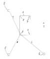
- FIG. 4is a schematic view of an AGV and a plurality of beacons, illustrating a first method by which the AGV determines its position and/or heading;
- FIG. 5is a schematic view of an AGV and a plurality of beacons, illustrating a second method by which the AGV determines its position and/or heading;
- FIG. 6is a flowchart of one method of determining heading and/or position information of a mobile unit
- FIG. 7is a flowchart of another method of determining heading and/or position information of a mobile unit.
- FIG. 8is a perspective view of an ultra-wideband radar bumper for a mobile vehicle
- FIG. 9is a perspective view of a conveyor sortation bed in which the present invention may be embodied.
- FIG. 10is plan, schematic view of a conveyor sortation system in which the present invention may be embodied.
- FIG. 11is a partial perspective view of a monorail system in which the present invention may be embodied.
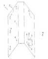
- FIG. 1An illustrative example of a material handling system, which may be in the form of an automatic guided vehicle (AGV) 20 , to which the present invention can be applied is depicted in FIG. 1 .
- AGV 20may be the type of vehicle which is described in more detail in U.S. Pat. No. 5,764,014 issued to Jakeway, the disclosure of which is hereby incorporated herein by reference.
- AGV 20includes a plurality of drive wheels 22 which are powered by motors 23 (FIG. 2) and drive the vehicle 20 .
- AGV 20further includes a front, steerable wheel 24 , a hitch 26 for towing trailers of material, a mechanical front bumper 28 , a battery storage compartment 30 for storing the batteries that provide power to the drive wheels 22 , and a local operator console 32 that allows the vehicle to be operated manually by a user. When local operator console 32 is not in use, AGV 20 guides itself automatically from destination to destination.
- AGV 20may also include a ground track sensor 34 that provides navigation information to the vehicle in a manner described more fully in U.S. Pat. No. 5,764,014, and an ultra-wideband radar bumper 36 that will be described in more detail herein. It will, of course, be understood that the present invention finds equal application to other types of AGVs and that AGV 20 is only one example of the many different types of AGVs to which the present invention may be applied.
- AGV 20includes a navigation system 38 that is illustrated in block diagram form in FIG. 2 .
- the navigation system 38includes ground track sensor 34 , a heading reference sensor 40 , a distance measuring encoder 42 , an angle encoder 44 , and a high frequency radio transceiver 46 .
- the operation of ground track sensor 34 , heading reference sensor 40 , distance measuring encoder 42 , and angle encoder 44is described in more detail in U.S. Pat. No. 5,764,014. Suffice it to say that ground track sensor 34 measures the rotation and angular position of a unloaded ground wheel 48 . This information is fed to a navigation computer 50 which uses the information, in conjunction with other navigation information, to determine the vehicle's location and heading.
- Navigation computer 50outputs commands to a steer board to steer front wheel 24 to cause the vehicle to stay on an intended path.
- Angle encoder 44measures the angular orientation of a caster wheel assembly on which front, steerable wheel 24 is mounted. This angular information is also fed into navigation computer 50 .
- Distance measuring encoder 42measures the number of rotations of front wheel 24 and feeds this information to navigation computer 50 for use in determining the vehicle's position and heading.
- Heading reference sensor 70provides information about the heading of the vehicle to navigation computer 50 , and may include a gyroscope.
- the gyroscope, angle and distance encoders, and ground track sensormay all be incremental sensors. That is, they may not, by themselves, be able to determine an absolute position or heading of the vehicle within a given frame of reference, but instead may only be able to sense changes in position and heading.
- high-frequency radio transceiver 46is provided. Transceiver 46 may be a device that sends and receives high-frequency radio signals, such as ultra-wideband signals, or other signals. Transceiver 46 may have multiple antennae placed at various points on the vehicle, allowing measurement of relative angles. These signals are used to determine the vehicle's absolute position and/or heading in a given frame of reference.
- transceiver 46In the illustrated navigation system, the absolute heading and/or position information provided by transceiver 46 to navigation computer 50 merely supplements that provided by the other navigation sensors. In this embodiment, transceiver 46 therefore does not need to provide position and heading information updates as quickly as it would if some or all of the other navigation sensors were removed. It will be understood by one skilled in the art that some or all of the other navigation sensors on vehicle 20 can be removed by simply increasing the rate at which transceiver 46 receives accurate position and heading measurement information. For example, if transceiver 46 provides updated heading information as quickly and accurately as the gyroscope in heading reference sensor 40 , then heading reference sensor 40 could be discarded. Therefore, navigation system 38 may or may not include sensors other than transceiver 46 . The operation of transceiver 46 will be described in more detail below.
- the AGV system 52includes at least one AGV, such as AGV 20 , which travels on a floor 55 throughout a plant or factory and which is adapted to carry loads.
- the loadsmay be carried on the top of the AGV, on one or more carts towed behind the AGV, or in any other manner.
- the AGVis able to steer itself automatically from one location to another based on instructions received from an off-board controller or from a person who manually enters an intended destination into an interface on the vehicle.
- AGV 20includes one or more incremental navigation sensors on-board which the vehicle uses to help determine its position and/or heading.
- AGV 20includes at least one transceiver 46 adapted to detect one or more stationary beacons 54 positioned at known locations throughout an environment.
- beacons 54are positioned along a ceiling 56 .
- Beacons 54could alternatively be placed at any other locations that are within range of detection by AGV 20 , as will be explained in more detail below.
- beacons 54use one or more of beacons 54 to periodically determine its position and/or heading. While AGV 20 receives information about its location and heading from the one or more incremental sensors it has on-board, these incremental sensors have to be initialized and also tend to produce errors that increase over time. Beacons 54 provide sufficient information to AGV 20 to allow itself to both initially determine its position, and to update its position and/or heading periodically as it travels throughout the plant. AGV 20 detects the one or more beacons 54 by way of one or more transceivers 46 positioned on-board vehicle 20 . (FIG. 2 ). In one embodiment of the present invention, beacons 54 may be various types of high frequency radio location devices such as the ultra-wideband transceivers disclosed in U.S. Pat. No.
- beacons 54are FMCW devices, such as those disclosed in U.S. Pat. Nos. 6,255,984 issued to Kreppold, et al. and 6,278,398 issued to Vossiek, et al., the disclosures of which are both hereby incorporated herein by reference.
- Beacons 54are installed at known locations throughout an environment in which one or more AGVs 20 are to operate. The location of beacons 54 is communicated to each of the AGVs 20 in any known manner, such as by wireless transmission, manual entry, downloading, or by any other means. Each AGV 20 uses signals transmitted between one or more beacons 54 and the transceiver(s) 46 it has on-board to determine its position and/or heading. An example of the manner in which the AGV is able to determine its position from the beacons 54 is depicted in FIG. 4 . Each beacon 54 emits a short, electromagnetic pulse that is detected by the one or more transceivers 46 located on AGV 20 .
- AGV 20By determining the time of flight for the emitted pulse to travel from one beacon 54 to a transceiver 46 , AGV 20 is able to calculate the distance between the beacon 54 which emitted the pulse and the transceiver 46 which detected the pulse. By determining the transceiver's distance to three or more beacons 54 , the vehicle is able to determine its position within the facility.
- a distance 31 a between transceiver 46 a and beacon 54 acan be computed by multiplying the propagation speed of the pulse by the time-of-flight. If the propagation speed is taken to be 300,000,000 meters/second, then the distance 31 a is 1.5 meters (300,000,000 m/s times 0.000000005 s). It is therefore known that transceiver 46 a lies somewhere on a sphere having a radius of 1.5 meters centered at beacon 54 a .
- beaconssuch as distances 31 b and 31 c , which correspond to the distances to beacons 54 b and 54 c (FIG. 4 ). Taking such measurements from at least three beacons should provide sufficient information for AGV 20 to be able to calculate its position within the facility, as would be understood by one skilled in the art. Such calculations can take place by any conventional means, such as by using one or more microprocessors, or by other means.
- navigation computer 50may be programmed to carry out these calculations.
- a separate processor associated directly with transceiver(s) 46can perform these calculations and communicate the result to navigation computer 50 .
- the details by which transceiver 46 determine their position from beacons 54are described more fully in U.S. Pat. No. 6,054,950.
- AGV 20may include a plurality of transceivers 46 arranged in an array of known configurations.
- the distances of each transceiver 46 to beacon 54 acan first be determined and then combined together, such as by averaging or other methods, to produce an estimate of vehicle position relative to beacon 54 a with greater accuracy. For example, if each transceiver 46 a-d in FIG.
- beacon 4measures it position away from beacon 54 a by determining the time of flight of a pulse emitted from beacon 54 a , these four distance determinations can be combined to produce a better estimate of the vehicle's distance from beacon 54 a , provided the location of each of the transceivers on-board the vehicle is known.
- vehicle 20can proceed to make additional distance measurements from other beacons 54 in a like manner and use these distance measurements to determine its position.
- the multiple measurements of vehicle distanceshould be made simultaneously, or nearly simultaneously, before they are combined together in order to avoid the need for accounting for possible movement of the vehicle between distance measurements. If the measurements are not made nearly simultaneously, such movement can be accounted for prior to combining the multiple measurements by way of the other navigation sensors, or by other methods, as would be understood by one skilled in the art.
- beacons 54 and transceivers 46can be used to calculate the vehicle's heading. Such heading calculations can be accomplished, in one embodiment, by determining the location within the facility of two transceivers 46 on-board AGV 20 . Provided the orientation of the vehicle transceivers with respect to the vehicle is known, the heading of the vehicle can be calculated. For example, suppose transceivers 46 a and 46 b are mounted to a vehicle such that a line drawn between the two transceivers points in the direction considered to be the heading of the vehicle 20 .
- the vehicledetermines the position of transceiver 46 a within a facility to be (x a , y a ), and the position of transceiver 46 b to be (x b , y b ), where the letters x and y refer to the two-axes of a coordinate frame of reference.
- the vehiclecan compute its heading within this frame of reference according to the following formula:
- the computed headingwill be an angular measurement from the x-axis of the coordinate frame of reference.
- An infinite headingwill correspond to the vehicle pointing parallel to the y-axis, while a heading of zero will correspond to the vehicle pointing parallel to the x-axis.
- the sign of the headingcan be used to determine which end of the vehicle is pointing in the direction of the calculated heading, as would be understood by one skilled in the art.
- the four transceivers 46 a-dcan be combined into six different unordered pairs, and each unordered pair used to calculate the vehicle's heading.) Combining these six measurements, such as by averaging, can yield an improvement in the accuracy of the resulting heading estimate.
- the calculation of heading according to the above equationwill produce a result that corresponds to the direction in which the vehicle is pointing.
- the direction in which the vehicle is pointingdoes not always equal the direction in which the vehicle is moving. For example, during turns or situations in which the vehicle may slip sideways, the vehicle may move in directions other than the direction in which it is pointed. In order to calculate the direction of the vehicle's movement in such situations, successive determinations in time of the vehicle's position can be used, as would be known by one skilled in the art.
- the transmission of signals from beacons 54can be synchronized in a wide variety of manners.
- One such manneruses a synchronization pulse that is transmitted to the beacons in either a wire or wireless fashion.
- the propagation time of the synchronization pulses to the various beaconsshould, of course, be taken into account when using this method.
- Other synchronization methodsare disclosed in the prior art, such as in U.S. Pat. No. 6,054,950 that can be used.
- each beacon 54may be assigned a unique pulse pattern that is communicated to, and stored in the memory of vehicle 20 , preferably at the time of the system installation.
- transceiver 46When transceiver 46 detects a particular pattern of pulses, it checks its memory for that signature pulse pattern to determine which beacon 54 emitted the pulse. Further, because vehicle 20 also stores the location of each beacon 54 in memory, it can correlate the detected pulse pattern to a particular location within the facility, thus enabling the vehicle to use the transmitted signals for position and heading determinations.
- beacons 54are designed to emit pulses only during defined time periods. When pulse patterns are emitted from beacons 54 , the particular pulse which is used for time of flight or time or arrival measurements can be any one or more of the multiple pulses emitted in the pattern.
- beacons 54could simply be assigned certain time slots in which they broadcast one or more pulses.
- the assignment of time slots to individual beacons 54is communicated to vehicle 20 so that vehicle 20 can determine which beacons' signals transceiver(s) 46 may be detecting at any given moment and correlate this information to the correct position location of the beacon.
- the assignment of time slotsmay preferably include time slots in which communications other than those in which time of flights or time of arrivals are measured.
- some time slotsmay be used to send synchronization signals between beacons 54 and/or transceiver 46 in order to allow the flight times and/or arrival times of various signals to be accurately measured and utilized.
- some time slotsmay be used to send communications to and from a central controller, other vehicles, or other devices.
- each transceiver 46may be programmed to time-stamp each signal it detects from a beacon 54 .
- the time stampcan be used to ensure that accurate measurements of flight times or arrival times are made. If multiple transceivers 46 are on-board a vehicle, such it is important to ensure that such time stamping each transceiver 46 is synchronized with the other transceivers. Such synchronization can be carried out using a synchronization pulse, or by other means.
- the on-board synchronizationcan be further enhanced by using interferometric methods.
- interferometric methodscan significantly increase the precision of the synchronization of the transceivers, thereby increasing the precision by which the differences in arrival times are measured, which in turn increases the accuracy of the vehicle's position and/or heading measurement.
- the heading and position of the vehiclecan be determined without calculating the flight times of signals emitted from beacons 54 .
- the position and heading of the vehicle 20is determined by comparing the differences in time in which one or more signals from a beacon 54 are detected by three or more transceiver antennae 46 positioned on the vehicle at known locations. This method is illustrated in FIG. 5 . By using this method, it is not necessary to know precisely when a signal was emitted from a beacon 54 . For example, suppose beacon 54 b in FIG. 5 emits a signal. This signal will travel a distance 33 a before it reaches, and is detected by, transceiver 46 a .
- the signalwill travel distances 33 b-d before it reaches, and is detected by, transceivers 46 b-d , respectively. Because the distances 33 a-d are different from each other, the time at which transceivers 46 a-d will detect the emitted signal will be different from each other. By comparing the relative times at which the signal is detected by the different transceivers, the position of the vehicle with respect to beacon 54 b can be determined. This is true regardless of whether the time of detection of the signal at each of the transceivers 46 a-d is different or simultaneous. Of course, it is necessary to know the relative positions of transceivers 46 a-d with respect to each other on the vehicle.
- the exact number of transceivers 46 a-d necessary to determine the position of the vehiclewill be partially dependent upon the arrangement of the beacons 54 . If all of the beacons are placed above the vehicle, the vehicle can use this information when the calculations of the vehicle's position yield two possible solutions, one of which is knowingly impossible—such as where one solution indicates the beacons are below the vehicle when in fact they are all positioned above the vehicle. In such a case, the vehicle would know that only the solution yielding a beacon position above the vehicles could be valid. If beacons are to be placed both above and below the vehicle, it may be necessary to add one more transceiver on vehicle 20 than would otherwise be necessary in order to determine the vehicle's position.
- the vehiclecan use this information to reduce the number of transceivers 46 which the vehicle would otherwise require, particularly if the vehicle only travels on a floor that is planar and parallel to the plane of the beacons.
- the number of transceivers 46 on vehicle 20 necessary for the vehicle to determine its positionis therefore dependent upon the arrangement of beacons 54 , as would be known by one skilled in the art.
- the heading of the vehiclecan also be determined by measuring the differences in arrival times of a beacon signal at the multiple transceivers 46 on the vehicle. Such a heading computation can be carried out, in one embodiment, by first determining the position of one of the transceivers 46 relative to the beacon 54 which emitted the signal. The heading can be computed by calculating the location of at least one other transceiver and then comparing its position to the position of the first transceiver.
- beacon 54 amight transmit a single signal that is detected by multiple transceivers 46 on vehicle 20 . Based on the times at which this signal arrives at each of the multiple transceivers, the vehicle can calculate its position and heading. Immediately after beacon 54 a broadcasts its signal, another beacon, such as beacon 54 b , could then emit a signal.
- the vehicle 20could then use this signal from beacon 54 b to perform another calculation of its position and heading. Assuming that the vehicle's position or heading has changed negligibly—or by an amount that can be estimated or measured—in the time interval between the signals from beacons 54 a and 54 b , the two calculations of the vehicle's position and heading could be combined to produce a more accurate measurement of heading and position. The combining of the calculations could be done by a simple averaging process, a least square method, or other methods. The accuracy of the determination of the vehicle's position and heading could be further enhanced by using measurements based on additional beacons, such as a third, a fourth, or even more beacons. As noted above, the calculations of the vehicle's heading and/or position can be performed by one or more processors, or by any other suitable means.
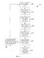
- a first method 57 for determining the vehicle's position and reading illustrated in FIG. 6one or more pulses are emitted at a step 58 .
- the pulsesmay be emitted from a transceiver 46 aboard the vehicle, or they may be emitted from a beacon 54 .
- the time of flight of the emitted pulse to a first sensoris determined.
- the reference to a sensor in FIGS. 6 and 7refers to transceiver 46 if the emitted signal came from a beacon 54 , or to a beacon 54 if the emitted pulse came from transceiver 46 .
- the present inventionfinds equal application to those systems in which times of flight or arrival times are measured based on signals emitted from the vehicle to the beacons, or vice versa.
- the time of flight of the emitted signal to a second sensoris determined.
- the time of flight of the emitted signal to another sensoris determined (the N th sensor).
- the total number of sensors used to measure time of flightsis represented by the variable N, and N may be any integer greater than or equal to one. Steps 60 b and c therefore may be optional in some embodiments.
- the distances from the pulse emitter to each pulse sensoris determined at step 62 .
- the distance informationis used to determine a positional relationship between the emitter and at least one sensor at step 64 .
- the positional relationshipmay be an absolute measurement of the vehicle's position within a facility, or only a relative measurement of the vehicle's position to one or more beacons 54 , depending on the number of time of flight measurements used.
- method 57may include an optional step 66 in which multiple positional relationships between the emitter and multiple sensors are combined into a single positional relationship. This optional step may be used when multiple sensors are present. By combining the positional relationship from multiple sensors into a single measurement, which may be done by averaging, a least square method, or other means, a more accurate positional relationship may be generated.
- the measurementsare combining based upon the knowledge of the physical location of each of the sensors relative to each other.
- the heading of the vehiclemay be determined based upon multiple position determinations from either step 64 or step 66 .
- Optional step 68is implemented after method 57 has cycled through steps 58 - 64 a sufficient number of times to provide sufficient position information by which the heading of the vehicle can be determined.
- a second method 69 of determining position and/or headingis illustrated in FIG. 7 .
- one or more electromagnetic pulsesare emitted at step 70 in the same manner as in step 58 .
- the arrival times of the emitted pulse at one or more sensorsare determined. The number of sensors can be varied between two or more.
- the differences in the arrival timesare determined at step 74 , and these differences are used to calculate an angular orientation between the emitter and sensors at step 76 in a manner that would be known to one skilled in the art.
- step 78which is optional, multiple angular orientations calculated in step 76 can be combined together into a single calculation of angular orientation, such as by averaging, a least square method, or other means.
- the angular orientation measurements from steps 76 and 78can optionally be used to determine the vehicle's position at step 80 .
- Step 80like step 68 in method 57 , can take place only after method 69 has cycled through steps 70 - 76 multiple times.
- the steps of methods 57 and 69may take place completely on-board vehicle 20 , completely off-board vehicle 20 , or some combination thereof.
- beacons 54 and transceivers 46While the above-description of beacons 54 and transceivers 46 has been based upon these devices communicating via ultra-wideband signals, it will be understood that the scope of the invention is not limited to the use of only ultra-wideband signals. Rather, the invention finds application in any electromagnetic energy emitting transmitters and receivers wherein the transmitted signals are sufficiently defined to be able to accurately determine when the signal was emitted, when the signal was detected, or both. Alternatively, frequency modulated continuous wave radar systems can be used for position and heading determinations, although other systems will suggest themselves to be skilled artisans. In addition to the beacons 54 and transceivers 46 described above, beacons 54 and transceivers 46 could alternatively comprise the localizers described in U.S. Pat. No. 6,002,708 issued to Fleming et al., the disclosure of which is hereby incorporated herein by reference.
- beacons 54 and transceivers 46for the navigation of AGV 20 can be augmented by using one or more incremental sensors, as noted above. Such incremental sensors are particularly desirable if beacons 54 and transceivers 46 do not provide fresh measurements of position or heading with sufficient frequency to properly guide the vehicle.
- the measurements of heading and/or position obtained from beacons 54 and transceivers 46can be combined with the position and heading information from the one or more incremental sensors to produce a more accurate estimate of the vehicle's heading and/or position.
- the combination of the incremental sensor information and the beacon/sensor informationcan be accomplished in any conventional manner, including through the use of a Kalman filter.
- a Kalman filtercan be used with any of the methods for determining heading or position described above.
- Navigation system 38utilizes beacons 54 , transceiver(s) 46 , and one or more processors, either separate from or part of navigation computer 50 , for combining and processing the signals received by transceivers 46 .
- the navigation systemcan be used either alone or in combination with other navigation sensors, such as the incremental sensors described above. If used in combination with other incremental sensors, the navigation system can be installed on original vehicles, or it can be added to existing AGVs.
- the navigation system of the present inventioncould be installed as a retrofit kit on pre-existing vehicles, such as, for example, those described in U.S. Pat. No. 5,280,901.
- Such vehiclesuse a gyroscope, wheel encoders, and a magnet sensor that detects magnets positioned at known locations on the floor of a plant to navigate.
- the navigation system of the present inventionBy installing the navigation system of the present invention on such a vehicle, one or more of the gyroscope wheel encoders and magnet sensors can be removed and replaced with the beacon/transceiver system of the present invention, which would provide the same or comparable navigation as the removed sensor or sensors.
- a navigation kit according to the present inventionprovides periodic updates of the vehicle's position and heading that allow it to replace one or more of these sensors.
- the navigation system of the present inventioncould therefore replace the magnet sensors of the vehicles disclosed in the '901 patent. Instead of using magnets for periodic updates, the vehicle would use the beacons and sensors for periodic updates of position and heading.
- the navigation system of the present inventioncould also eliminate the need for the gyroscope and one or more of the wheel encoders.
- the navigation kit of the present inventioncould also be used to replace one or more navigation sensors on other types of vehicle's, such as those that use laser reflectors or those that use transponders buried in the floor, as well as other types.
- beacons 54are mounted in any known manner at locations throughout the facility, such as on a ceiling, on the tops of racks or other stationary structures, in the floor, or in still other locations. Once one or more of these beacons have been installed, the position of at least three beacons are determined by surveying or other means. After the location of these first beacons are determined, the position of the other beacons can be determined in a variety of manners using common surveying techniques for measurement of beacon relative locations and subsequent error reducing analytical algorithms. The need to physically survey every single beacon in the facility during installation can therefore be avoided. In order for the beacons to be able to determine their positions with respect to each other, it is necessary for them to be able to both transmit and receive signals, i.e. to be transceivers. Transceivers that can be used for this purpose are described in the U.S. Pat. No. 6,054,950 patent.
- transceivers 46on board AGV 20 does imply that only transceivers can be used on board vehicle 20 in accordance with the present invention.
- transceivers 46could simply be receivers.
- transceivers 46could simply be transmitters.
- beacons 54could be either transmitters or receivers in these different situations.
- the term “beacon” as used in this applicationis therefore intended to cover receivers, transmitters, and transceivers.
- ultra-wideband signalscan be used for communication in material handling systems, such as AGV system 52 .
- each AGVincludes an ultra-wideband transceiver that may or may not be the same as a transceiver 46 .
- the communicationcan be directly between vehicles, between each vehicle and a central station, or some combination thereof.
- the communicationscan include any type of information, such as destination information, load information, blocking information, or other information.
- Such communicationcould be accomplished by transmissions during the intervals between navigation signals from the beacons, or the navigation signals from the beacons could themselves be sent with a certain order and/or frequency that defined one or more messages.
- the ultra-wideband communicationscould also be implemented on AGVs that did not use ultra-wideband navigation techniques.
- High frequency radio transmitterssuch as ultra-wideband transmitters
- Such transmittersmay broadcast one or more messages indicating that a load is to be transported, the contents of the load, the destination of the load, or other information concerning the load. The initiation of such signals can be implemented by a worker pressing a button on the transmitter, or by taking other steps to cause the transmitter to transmit such a message.
- the transmittermay also broadcast its location, or signals sufficient for the AGVs to determine its location.
- Each AGVmay include a controller for determining which of the available AGVs should respond to the message, or a central controller may dictate which AGV should respond to the message.
- Such transmittersallow loads to be monitored by a central control system throughout their movement in the facility.
- the transmittersmay also respond to a centralized request for information in order to allow automatic inventories to be taken of material in a facility.
- Beacons 54could also be placed on individual AGVs, other mobile vehicles in the facility—such as driver-guided fork-lift trucks—or on stationary objects, in order to avoid collisions with these objects.
- vehicles 20steer themselves accordingly to avoid collisions with certain designated beacons, such as those on fork-lift trucks or at other occupied locations.
- a controller on vehicle 20implements an appropriate velocity change to help avoid a collision with the fork-lift truck. In this manner, plant safety can be improved while minimizing the costs associated with collisions.
- AGV 20includes a high frequency radio radar module or bumper 36 located at a position on the vehicle that enables it to detect nearby objects (FIG. 1 ).
- the high frequency radio radarcan be any conventional module, such as the ultra-wideband radar modules disclosed in U.S. Pat. No. 5,805,110 issued to McEwan, the disclosure of which is hereby incorporated herein by reference.
- the radar bumpercould comprise a phased array of high frequency radio antennas 82 (FIG. 8 ).
- a high frequency pulseis emitted from one of the individual antennas 84 and it reflects off of an object 86 back to the array 82 .
- the antennas 84detect the reflected signal at different times based upon the location of object 86 .
- a processorcompares these different detection times to determined the position of the object in a manner that would be known to one skilled in the art. While radar bumper 36 is depicted as a single bumper on the front of vehicle 20 in FIG. 1, it will be understood that multiple radar bumpers could be incorporated onto a vehicle, such as at the back of the vehicle, which is particularly useful for vehicles that are capable of bi-directional travel. For vehicles capable of side-to-side movement, additional radar bumpers 36 could be placed on the sides of the vehicle to determine whether obstacles are blocking the vehicle's side-to-side movement.
- the detectable range of the radar bumpers 36can be set to any desirable distance, but would preferably be very close to the vehicle for side bumpers 36 , in front of mechanical bumper 28 for the front bumper 36 , and close to the back end of the vehicle for rear bumper 36 .
- Object detection rangecan also be controllable during operation to allow a safety zone tailored to the vehicle's current task.
- the detected information from bumper 36could be forwarded to navigation computer 50 , which would issue any appropriate steering commands to make in light of the detected object.
- the high frequency radio radar module 36can be used for a variety of purposes.
- the radarcan be used to detect objects that obstruct the path of the vehicle, such as other vehicles, fork-lift trucks, pallets, personnel, or any other objects that might get in the way of a vehicle's path.
- AGV 20may be programmed to either stop and wait until the obstruction is removed, or to follow an alternate route to avoid the obstacle.
- the radarcan be used for accurately stopping the vehicle at transfer stations, battery recharging stations, or any other locations where the vehicle must be accurately positioned.
- the radarindicates to the vehicle its distance from a reference structure at or near the station. The vehicle stops itself at a predetermined location with respect to the reference structure.
- the reference structurecan be any structure which is detectable by high frequency radio radar, including structures that exist within the facility prior to the AGV installation, or structures that are specifically added to provide references for the AGVs.
- the reference structuresmay be different for different stations, and AGV 20 is programmed to store the appropriate data concerning the reference structure for each station.
- the high frequency radio radar modulecan also be used for picking up loads that are not oriented at pre-determined orientations, such as loads that are deposited on the floor or other structure from a fork-lift truck. If AGV 20 is equipped with a fork-lifting capability, the high frequency radio radar module can be positioned to detect the orientation of the pallet. Based on the detected orientation of the pallet, AGV 20 steers itself appropriately to insert its fork-lift prongs into the pallet, pick it up, and transport it to an intended destination.
- the various uses for the high frequency radio radar module described aboveare not mutually exclusive, but rather a single AGV can use one or more radar modules to perform each of the functions described above, as well as other functions.
- beacons 54 and transceivers 46can be used as a position monitoring system for monitoring the position of AGVs, manned vehicles, such as fork-lift trucks, material loads, or a mix of these items.
- Such monitoring systemscan be used independently of any navigation functions provided by beacons 54 and transceivers 46 , or they can be used in combination with such navigational functions.
- a plurality of beacons 54can be positioned at known locations throughout an environment and one or more transceivers 46 can be positioned on-board the vehicle(s) and/or loads, or vice versa.
- the vehiclemay be either an AGV, a manned vehicle, or some other type of mobile unit.
- the loadmay be a fork-lift pallet, a carton, an individual package, or some other material unit whose position may change in the facility.
- the position of the load and/or the vehicleis determined in accordance with one of the methods previously described.
- the heading of the vehiclecan also be determined in accordance with one of the methods previously described.
- FIG. 2illustrates a computer, 116 which may receive wireless transmissions via antenna 120 from transceivers 46 of vehicle 20 's location and/or heading.
- the processormay visually display the location of the vehicle and/or load, such as via a computer monitor; may record the movement of the vehicle and/or load over a given time period for later viewing or analysis; or may perform a combination of both of these functions.
- computer 116includes a display 118 for displaying the position of vehicle 20 , and computer 116 may be programmed to record and analyze the movement of vehicle 20 over time.
- the processorincludes a visual display, such as display 118 , the movement of the mobile units and material throughout the environment can be monitored by a person. If the processor records the movements of the mobile units, this information can later be analyzed to determine the efficiency of the movement of the mobile units, the amount of usage of certain vehicles, and other aspects.
- the processormay be located anywhere, including on one of the vehicles, off of the vehicles at a location within the environment, or even outside the environment of the mobile units.
- the transmission of the position information to the processormay be accomplished by radio signals, ultra-wideband signals, hard wires, or by other means.
- the position informationcan also be used by a controller on-board the vehicle for navigation and steering, as discussed above.
- the monitoring of mobile units and/or materialcan be accomplished by having the individual transceivers 46 , and associated circuitry, determine their position and/or heading, and then transmit this information to a central monitoring device.
- the central monitoring devicecan determine the mobile unit's and/or material's location directly.
- transceivers 46 and beacons 54are only being used to monitor the location of mobile object, rather than to provide navigation information, in this embodiment, the rate at which updated position information is provided can be substantially less than for those applications in which navigation information is generated. For example, for the monitoring of mobile loads, it may be sufficient to provide updated position information every five seconds where the vehicle travels up to one meter/second and the location information is accurate to approximately thirty seconds.
- high frequency radio location signalsmay also be used in accordance with the present invention to identify material being moved throughout a warehouse or other facility.
- An example of such a tag 88is depicted attached to an article 90 traveling on a conveyor 92 in FIG. 9 .
- the high frequency radio location tag 88is manufactured in a known manner to reflect high frequency radio location signals it receives according to a predefined patterns. The signals that are received and reflected may be ultra-wideband signals.
- a tag readeremits a high frequency radio location signal which is reflected by the tag and detected by the tag reader.
- the tag readerpasses this information onto appropriate controls in the material handling environment to ensure that the article is properly routed throughout the facility.
- the controlsmay be aware of the correlation between the unique reflective pattern of an individual tag and the information associated with that tag.
- the high frequency radio location tagsmay therefore be used to replace bar codes, which require optical alignment for reading, and relatively clean surfaces on which the bar codes are printed. By using high frequency radio location, no particular orientation of the article is necessary for reading the information contained on the high frequency radio location tag.
- Such high frequency radio location tagsfind particular suitability with articles traveling on conveyor systems throughout a warehouse.
- the high frequency radio location tagsare preferably constructed so that they do not require any power to operate, either directly or by induction. Their unique signal is merely the result of their unique reflection pattern of the emitted signal or signals. In the example of FIG.
- the tags 88may be read by a reader positioned upstream of conveyor 92 .
- the read informationmay be passed to a divert controller 94 (FIG. 10) which uses the information to determine which of the multiple branch conveyors the article 90 should be diverted to.
- Divert controller 94sends commands to activate the appropriate divert shoes 98 which cause the package 90 to be appropriately diverted.
- the construction and generation of divert shoes 98may be made in accordance with the system described in commonly assigned, co-pending U.S. patent application Ser. No. 09/968,743 filed Sep. 28, 2001, or the system described in U.S. Pat. No. 5,127,510 issued to Cotter et al., the disclosures of both of which are incorporated herein by reference. Conventional constructions and operations may also be used.
- UWB transceiverssuch as transceivers 46
- transceivers 46can also be used in other material handling applications outside AGVs.
- Such transceiverscan be incorporated into components of material handling systems for automatic identification and configuration of components of the material handling system.
- sortation systems for conveyorsthere may be a number of individual divert control modules 100 associated with each branch conveyor 96 on a given sortation conveyor 92 (FIG. 10 ).
- the control modules 100control, by way of example, the mechanisms for positively displacing articles 90 off of the sortation conveyor onto an adjacent branch conveyor 96 .
- the precise number and location of each of the sortation modules 100may vary according to the particular installation.
- a higher level controller of the overall sortation systemsuch as divert controller 94
- divert controller 94it is often necessary for a higher level controller of the overall sortation system, such as divert controller 94 , to know the position of each of the control modules 100 so that the higher level controller 94 can send divert signals to the correct control module 100 when a particular article 90 is to be diverted to a particular branch conveyor 96 .
- a higher level controller of the overall sortation systemsuch as divert controller 94
- transceivers 46By placing transceivers 46 in each divert control module, the distance of each control module down the length of the sortation conveyor can automatically be determined. Such distances are determined in any one of the manners previously described herein, and can be determined in conjunction with a transceiver 46 placed at a reference location, such as the upstream end of the sortation conveyor 92 .
- the transceivers 46can also be used as wireless communication devices.
- the higher level controlleris also provided with a UWB transceiver that communicates wirelessly with the UWB transceivers 46 .
- the communicationscan include commands from the higher level controller to the divert modules, status requests, feedback from the modules to the controller, and other sorts of information.
- the use of such wireless communicationseliminates the need for hard wiring connections, such as communications bus 102 , between the higher level controller 96 and each divert control module 100 .
- Beacons 54 and transceivers 46can also be used with monorail material handling systems, such as overhead electrified monorails.
- An illustrative example of one such monorailis depicted in FIG. 11 .
- Monorail 104extends throughout a facility or plant in a pre-defined arrangement.
- Monorail 104includes a number of buss bars 106 which supply power and/or communications to a vehicle 108 that is attached to, and hangs downwardly from, rail 104 .
- Vehicle 108includes a number of wheels 110 that allow it to move along rail 104 and transport articles 90 , such as via a platform 112 , or by other means.
- At least one motor 114is included and powers one of the wheels 110 for movement on rail 104 .
- Vehicles 108may carry articles 90 undergoing manufacture between workstations. Vehicle 108 may stop at one or more of these workstations to allow time for robots or workers to perform work on the item being manufactured.
- Vehicle 108may include a transceiver 46 attached at any suitable location that communicates with beacons 54 placed throughout the facility. The beacons 54 emit signals which transceiver 46 uses to determine its position with respect to the beacons 54 . The position may be a one-dimensional, two-dimensional or three-dimensional position determination. Vehicle 108 may use the position determination to determine precisely where it should stop within a given workstation. Vehicle 108 may also use transceiver 46 as a communications device for wirelessly transmitting information between itself and a controller. Such communications may be ultra-wideband communications, or other types of high frequency communications.
Landscapes
- Engineering & Computer Science (AREA)
- Physics & Mathematics (AREA)
- General Physics & Mathematics (AREA)
- Radar, Positioning & Navigation (AREA)
- Remote Sensing (AREA)
- Aviation & Aerospace Engineering (AREA)
- Automation & Control Theory (AREA)
- Control Of Position, Course, Altitude, Or Attitude Of Moving Bodies (AREA)
- Radar Systems Or Details Thereof (AREA)
Abstract
Description
Claims (38)
Priority Applications (1)
| Application Number | Priority Date | Filing Date | Title |
|---|---|---|---|
| US10/209,766US6799099B2 (en) | 2001-08-02 | 2002-07-31 | Material handling systems with high frequency radio location devices |
Applications Claiming Priority (3)
| Application Number | Priority Date | Filing Date | Title |
|---|---|---|---|
| US30956801P | 2001-08-02 | 2001-08-02 | |
| US31802901P | 2001-09-10 | 2001-09-10 | |
| US10/209,766US6799099B2 (en) | 2001-08-02 | 2002-07-31 | Material handling systems with high frequency radio location devices |
Publications (2)
| Publication Number | Publication Date |
|---|---|
| US20030028323A1 US20030028323A1 (en) | 2003-02-06 |
| US6799099B2true US6799099B2 (en) | 2004-09-28 |
Family
ID=26976897
Family Applications (1)
| Application Number | Title | Priority Date | Filing Date |
|---|---|---|---|
| US10/209,766Expired - Fee RelatedUS6799099B2 (en) | 2001-08-02 | 2002-07-31 | Material handling systems with high frequency radio location devices |
Country Status (5)
| Country | Link |
|---|---|
| US (1) | US6799099B2 (en) |
| AU (1) | AU2002333320A1 (en) |
| CA (1) | CA2455521A1 (en) |
| MX (1) | MXPA04001021A (en) |
| WO (1) | WO2003012470A2 (en) |
Cited By (36)
| Publication number | Priority date | Publication date | Assignee | Title |
|---|---|---|---|---|
| US20040128023A1 (en)* | 2002-12-31 | 2004-07-01 | Lg.Philips Lcd Co., Ltd. | Substrate transfer system |
| US20050080524A1 (en)* | 2003-10-14 | 2005-04-14 | Tae-Eun Park | AGV control system and method |
| US20050125247A1 (en)* | 2003-05-13 | 2005-06-09 | Ding Steven A. | Industrial vehicle fleet management system |
| US20050219056A1 (en)* | 2004-03-30 | 2005-10-06 | Mchugh Daniel | Method and system for tracking individuals and providing related electronic notifications |
| US20050246078A1 (en)* | 2004-04-30 | 2005-11-03 | Jan Vercammen | Automatically guided vehicle with improved navigation |
| US20060000693A1 (en)* | 2001-06-07 | 2006-01-05 | Rapistan Systems Advertising Corp. | Tiered control architecture for material handling |
| US20060224307A1 (en)* | 2005-03-31 | 2006-10-05 | Deere & Company, A Delaware Corporation | System and method for determining a position of a vehicle with compensation for noise or measurement error |
| US20060271252A1 (en)* | 2005-05-26 | 2006-11-30 | Murata Kikai Kabushiki Kaisha | Transportation system |
| US20070007080A1 (en)* | 2005-05-31 | 2007-01-11 | Still Gmbh | Industrial truck with an electrical control unit |
| US20070076638A1 (en)* | 2005-10-05 | 2007-04-05 | Honeywell International Inc. | Localization for low cost sensor network |
| US7201316B2 (en)* | 2003-03-04 | 2007-04-10 | United Parcel Service Of America, Inc. | Item tracking and processing systems and methods |
| US7342496B2 (en) | 2000-01-24 | 2008-03-11 | Nextreme Llc | RF-enabled pallet |
| US20080154691A1 (en)* | 2006-12-13 | 2008-06-26 | Wellman Timothy A | Fleet management system |
| US20080189003A1 (en)* | 2007-02-07 | 2008-08-07 | Jeremy Gillula | Sensor fusion system for vehicle autonomy in a theme park |
| US20080202402A1 (en)* | 2007-02-26 | 2008-08-28 | Giles David L | System for rapid, secure tarnsport of cargo by sea, and monohull fast ship and arrangement and method for loading and unloading cargo on a ship |
| US20080213073A1 (en)* | 2007-03-01 | 2008-09-04 | Tesseract International, Inc. | Port storage and distribution system for international shipping containers |
| US20080262669A1 (en)* | 2006-09-22 | 2008-10-23 | Jadi, Inc. | Autonomous vehicle controller |
| US20090076664A1 (en)* | 2007-09-13 | 2009-03-19 | Mccabe Paul P | Control system for a pallet truck |
| US20090118908A1 (en)* | 2004-06-21 | 2009-05-07 | Fuller Bros., Inc. | Vehicle Safety Zone System |
| US20100228428A1 (en)* | 2006-12-13 | 2010-09-09 | Crown Equipment Corporation | Information system for industrial vehicles |
| US20110054731A1 (en)* | 2009-08-31 | 2011-03-03 | Derose Lynn Ann | System and method for bi-directional wireless information transfer |
| US20110130899A1 (en)* | 2008-07-16 | 2011-06-02 | Siemens S.A.S. | System for determining movement properties of a guided vehicle |
| US8077040B2 (en) | 2000-01-24 | 2011-12-13 | Nextreme, Llc | RF-enabled pallet |
| WO2012166970A1 (en)* | 2011-05-31 | 2012-12-06 | John Bean Technologies Corporation | Deep lane navigation system for automatic guided vehicles |
| US8583314B2 (en) | 2009-08-12 | 2013-11-12 | Crown Equipment Corporation | Information system for industrial vehicles |
| US9354070B2 (en) | 2013-10-31 | 2016-05-31 | Crown Equipment Corporation | Systems, methods, and industrial vehicles for determining the visibility of features |
| US9658622B2 (en) | 2015-05-06 | 2017-05-23 | Crown Equipment Corporation | Industrial vehicle for identifying malfunctioning sequenced tag and tag layout for use therewith |
| US9818003B2 (en) | 2015-05-06 | 2017-11-14 | Crown Equipment Corporation | Diagnostic tag for an industrial vehicle tag reader |
| US9864371B2 (en) | 2015-03-10 | 2018-01-09 | John Bean Technologies Corporation | Automated guided vehicle system |
| US9886036B2 (en) | 2014-02-10 | 2018-02-06 | John Bean Technologies Corporation | Routing of automated guided vehicles |
| US20180081361A1 (en)* | 2016-09-20 | 2018-03-22 | Waymo Llc | Devices and Methods for a Sensor Platform of a Vehicle |
| US9984341B2 (en) | 2006-12-13 | 2018-05-29 | Crown Equipment Corporation | Information system for industrial vehicles including cyclical recurring vehicle information message |
| CN108549386A (en)* | 2018-05-22 | 2018-09-18 | 汇专科技集团股份有限公司 | AGV trolleies managing and control system and method |
| US10600256B2 (en) | 2006-12-13 | 2020-03-24 | Crown Equipment Corporation | Impact sensing usable with fleet management system |
| US11225404B2 (en) | 2006-12-13 | 2022-01-18 | Crown Equipment Corporation | Information system for industrial vehicles |
| US12380373B2 (en) | 2009-09-01 | 2025-08-05 | Crown Equipment Corporation | Information system for industrial vehicles including cyclical recurring vehicle information message |
Families Citing this family (50)
| Publication number | Priority date | Publication date | Assignee | Title |
|---|---|---|---|---|
| US7111693B1 (en)* | 2002-11-26 | 2006-09-26 | The Charles Machine Works, Inc. | System and method for locating and tracking a boring tool |
| FI114827B (en)* | 2003-07-03 | 2004-12-31 | Sandvik Tamrock Oy | Method and system for monitoring the location of a mining vehicle |
| FI115414B (en) | 2003-07-03 | 2005-04-29 | Sandvik Tamrock Oy | Arrangement for monitoring the location of the mining vehicle in the mine |
| DE10341286A1 (en)* | 2003-09-04 | 2005-04-28 | Daimler Chrysler Ag | Access control system for vehicles |
| DE10358857A1 (en)* | 2003-12-16 | 2005-07-21 | Robert Bosch Gmbh | Distance measuring device for control |
| US7383053B2 (en)* | 2004-04-28 | 2008-06-03 | Lawrence Livermore National Security, Llc | Position estimation of transceivers in communication networks |
| ES2262422B1 (en)* | 2005-01-17 | 2007-11-16 | Miguel Teran Garrido | LARGE SCALE SYSTEM OF A DIGITALIZED DESIGN. |
| DE102005009579B4 (en) | 2005-02-28 | 2010-04-22 | ASTRA Gesellschaft für Asset Management mbH & Co. KG | Method for locating a detector wafer |
| EP3067771B1 (en) | 2006-03-17 | 2017-11-08 | iRobot Corporation | Robot confinement |
| US7912574B2 (en)* | 2006-06-19 | 2011-03-22 | Kiva Systems, Inc. | System and method for transporting inventory items |
| CN102173368A (en)* | 2008-04-18 | 2011-09-07 | 雷蒙德股份有限公司 | System for evaluating industrial vehicle performance |
| DE102008030546A1 (en)* | 2008-06-27 | 2009-12-31 | Siemens Aktiengesellschaft | Control for an autonomous transport vehicle and method for operating an autonomous transport vehicle |
| US8364309B1 (en)* | 2009-07-14 | 2013-01-29 | Bailey Bendrix L | User-assisted robot navigation system |
| DE102010037195A1 (en)* | 2010-08-27 | 2012-03-01 | Benedikt Hieronimi | System for detecting radio frequency transceivers and their uses |
| US20120316722A1 (en)* | 2010-12-10 | 2012-12-13 | Zeitler David W | Advanced navigation and guidance system and method for an automatic guided vehicle (agv) |
| WO2012158906A1 (en) | 2011-05-19 | 2012-11-22 | Metrom Rail, Llc | Collision avoidance system for rail line vehicles |
| JP5904475B2 (en)* | 2011-10-10 | 2016-04-13 | ボルボ グループ ノース アメリカ,エルエルシー | Garbage truck control system and method for controlling garbage truck |
| US9702707B2 (en) | 2011-12-22 | 2017-07-11 | AppLabz, LLC | Systems, methods, and apparatus for providing indoor navigation using optical floor sensors |
| US9513127B2 (en)* | 2011-12-22 | 2016-12-06 | AppLabz, LLC | Systems, methods, and apparatus for providing indoor navigation |
| US9243918B2 (en) | 2011-12-22 | 2016-01-26 | AppLabz, LLC | Systems, methods, and apparatus for providing indoor navigation using magnetic sensors |
| US9120568B2 (en)* | 2012-06-11 | 2015-09-01 | Lockheed Martin Corporation | Autonomous resupply system and method |
| US20140102859A1 (en) | 2012-10-12 | 2014-04-17 | Mckesson Automation Inc. | Apparatuses, systems, and methods for dispensing medications from a central pharmacy to a patient in a healthcare facility |
| US9150119B2 (en) | 2013-03-15 | 2015-10-06 | Aesynt Incorporated | Apparatuses, systems, and methods for anticipating and delivering medications from a central pharmacy to a patient using a track based transport system |
| US11814088B2 (en) | 2013-09-03 | 2023-11-14 | Metrom Rail, Llc | Vehicle host interface module (vHIM) based braking solutions |
| US20150060608A1 (en) | 2013-09-03 | 2015-03-05 | Metrom Rail, Llc | Rail Vehicle Signal Enforcement and Separation Control |
| US10368295B2 (en)* | 2015-05-26 | 2019-07-30 | FreeFlight Systems, Inc. | Unmanned aerial vehicle guidance and communication device with system and method |
| ITUA20161460A1 (en)* | 2016-03-08 | 2017-09-08 | Weflex Soc A Responsabilita Limitata | GOODS TRACKING SYSTEM FOR WAREHOUSE LOGISTICS |
| CN106314484B (en)* | 2016-08-09 | 2018-08-07 | 北京永安信通科技股份有限公司 | Vehicle positioning device and the mine locomotive for including the vehicle positioning device |
| CA3026002C (en)* | 2016-09-06 | 2021-04-20 | Advanced Intelligent Systems Inc. | Mobile work station for transporting a plurality of articles |
| US10304342B2 (en)* | 2016-11-08 | 2019-05-28 | Ge Aviation Systems Llc | Ground-based data acquisition system |
| CN110944926A (en)* | 2016-11-08 | 2020-03-31 | 科尼起重机全球公司 | System for radio positioning of transport vehicles for containers |
| DE102017102116A1 (en)* | 2017-02-03 | 2018-08-09 | Jungheinrich Aktiengesellschaft | Method and system for determining the position of at least one industrial truck |
| US10136259B1 (en) | 2017-05-03 | 2018-11-20 | Intermec, Inc. | Pick and put location verification utilizing RF received signal strength |
| CN107132847A (en)* | 2017-06-22 | 2017-09-05 | 福州大学 | A kind of AGV embedded control systems navigated based on tape and control method |
| US11349589B2 (en) | 2017-08-04 | 2022-05-31 | Metrom Rail, Llc | Methods and systems for decentralized rail signaling and positive train control |
| CN108646750B (en)* | 2018-06-08 | 2021-05-07 | 杭州电子科技大学 | Portable factory AGV following method based on UWB non-base station |
| US11580613B2 (en)* | 2019-06-28 | 2023-02-14 | Light Line Delivery Corp. | Parcel conveyance system |
| US11232388B2 (en)* | 2019-11-22 | 2022-01-25 | Accenture Global Solutions Limited | Automated guided vehicle systems for retrieving hems |
| DE102019132024A1 (en)* | 2019-11-26 | 2021-05-27 | Sick Ag | security system |
| EP3910434A1 (en)* | 2020-05-15 | 2021-11-17 | TRUMPF Werkzeugmaschinen GmbH + Co. KG | Location system with uwb infrastructure and discovery infrastructure |
| EP3964911B1 (en)* | 2020-09-03 | 2023-08-02 | Volvo Autonomous Solutions AB | A method of controlling the working scheme of an autonomous working machine at a worksite |
| WO2022076330A1 (en)* | 2020-10-05 | 2022-04-14 | Crown Equipment Corporation | Systems and methods for relative pose sensing and field enforcement of materials handling vehicles using ultra-wideband radio technology |
| CN112437403A (en)* | 2020-11-06 | 2021-03-02 | 易普森智慧健康科技(深圳)有限公司 | Self-control operation method and device of robot |
| DE102020133787A1 (en) | 2020-12-16 | 2022-06-23 | Sick Ag | Security system and method using a security system |
| DE102020133788A1 (en) | 2020-12-16 | 2022-06-23 | Sick Ag | Security system and a method for localization |
| DE102020133789A1 (en) | 2020-12-16 | 2022-06-23 | Sick Ag | Security system and method using a security system |
| DE102021203641A1 (en)* | 2021-04-13 | 2022-10-13 | Top Seven Gmbh & Co. Kg | Method, vehicle, system and computer program for determining and/or improving a position estimate of a vehicle |
| EP4348542A1 (en)* | 2021-06-02 | 2024-04-10 | Lineage Logistics, LLC | Swapping task assignments to determine task selection |
| CN114803861B (en)* | 2022-04-18 | 2023-01-24 | 中国矿业大学 | High-precision positioning system and positioning method for coal mine underground single-rail crane |
| CN114933130A (en)* | 2022-05-07 | 2022-08-23 | 苏州索服电子科技有限公司 | Intelligence SMT material car and UWB communication system based on UWB location technique |
Citations (37)
| Publication number | Priority date | Publication date | Assignee | Title |
|---|---|---|---|---|
| US3757290A (en) | 1971-03-12 | 1973-09-04 | Sperry Rand Corp | Automatic vehicle monitoring system |
| US4541049A (en)* | 1980-10-02 | 1985-09-10 | Ab Volvo | Method for updating in a wheeled vehicle steered by dead reckoning |
| WO1988005938A1 (en) | 1987-02-06 | 1988-08-11 | Kabushiki Kaisha Komatsu Seisakusho | Vehicle navigator |
| US4956777A (en)* | 1988-06-09 | 1990-09-11 | R. J. Reynolds Tobacco Company | Automatic vehicle control system |
| US5111401A (en)* | 1990-05-19 | 1992-05-05 | The United States Of America As Represented By The Secretary Of The Navy | Navigational control system for an autonomous vehicle |
| US5202832A (en)* | 1991-01-29 | 1993-04-13 | R. R. Donnelley & Sons Co. | Material handling automation system using portable transfer module |
| US5283739A (en)* | 1985-08-30 | 1994-02-01 | Texas Instruments Incorporated | Static collision avoidance method for multiple automatically guided vehicles |
| GB2274521A (en) | 1993-01-11 | 1994-07-27 | Hitachi Ltd | Production control system |
| US5438517A (en) | 1990-02-05 | 1995-08-01 | Caterpillar Inc. | Vehicle position determination system and method |
| US5510800A (en) | 1993-04-12 | 1996-04-23 | The Regents Of The University Of California | Time-of-flight radio location system |
| US5687169A (en) | 1995-04-27 | 1997-11-11 | Time Domain Systems, Inc. | Full duplex ultrawide-band communication system and method |
| US5764696A (en) | 1995-06-02 | 1998-06-09 | Time Domain Corporation | Chiral and dual polarization techniques for an ultra-wide band communication system |
| US5805110A (en) | 1994-12-19 | 1998-09-08 | The Regents Of The University Of California | Impulse radar with swept range gate |
| US5812081A (en) | 1984-12-03 | 1998-09-22 | Time Domain Systems, Inc. | Time domain radio transmission system |
| US5832035A (en) | 1994-09-20 | 1998-11-03 | Time Domain Corporation | Fast locking mechanism for channelized ultrawide-band communications |
| US5901172A (en) | 1997-06-11 | 1999-05-04 | Multispectral Solutions, Inc. | Ultra wideband receiver with high speed noise and interference tracking threshold |
| US5907427A (en) | 1997-10-24 | 1999-05-25 | Time Domain Corporation | Photonic band gap device and method using a periodicity defect region to increase photonic signal delay |
| US5907293A (en) | 1996-05-30 | 1999-05-25 | Sun Microsystems, Inc. | System for displaying the characteristics, position, velocity and acceleration of nearby vehicles on a moving-map |
| US5952956A (en) | 1984-12-03 | 1999-09-14 | Time Domain Corporation | Time domain radio transmission system |
| US5960031A (en) | 1994-09-20 | 1999-09-28 | Time Domain Corporation | Ultrawide-band communication system and method |
| US5969663A (en) | 1986-06-03 | 1999-10-19 | Time Domain Corporation | Time domain radio transmission system |
| US6002708A (en) | 1994-07-22 | 1999-12-14 | Aether Wire & Location, Inc. | Spread spectrum localizers |
| US6026125A (en) | 1997-05-16 | 2000-02-15 | Multispectral Solutions, Inc. | Waveform adaptive ultra-wideband transmitter |
| US6054950A (en) | 1998-01-26 | 2000-04-25 | Multispectral Solutions, Inc. | Ultra wideband precision geolocation system |
| US6091374A (en) | 1997-09-09 | 2000-07-18 | Time Domain Corporation | Ultra-wideband magnetic antenna |
| US6111536A (en) | 1998-05-26 | 2000-08-29 | Time Domain Corporation | System and method for distance measurement by inphase and quadrature signals in a radio system |
| US6133876A (en) | 1998-03-23 | 2000-10-17 | Time Domain Corporation | System and method for position determination by impulse radio |
| WO2000071442A2 (en) | 1999-05-21 | 2000-11-30 | Siemens Aktiengesellschaft | Array for transporting goods |
| US6173904B1 (en) | 1996-06-07 | 2001-01-16 | John A. Doherty | Apparatus and system for synchronized application of one or more materials to a surface from a vehicle and control of a vehicle mounted variable position snow removal device |
| US6177903B1 (en) | 1999-06-14 | 2001-01-23 | Time Domain Corporation | System and method for intrusion detection using a time domain radar array |
| US6218979B1 (en) | 1999-06-14 | 2001-04-17 | Time Domain Corporation | Wide area time domain radar array |
| US6239741B1 (en) | 1998-07-20 | 2001-05-29 | Multispectral Solutions, Inc. | UWB dual tunnel diode detector for object detection, measurement, or avoidance |
| US6304623B1 (en) | 1998-09-03 | 2001-10-16 | Time Domain Corporation | Precision timing generator system and method |
| US6445336B2 (en)* | 2000-02-28 | 2002-09-03 | Aisin Seiki Kabushiki Kaisha | Radar device and on-vehicle radar device |
| US6473686B2 (en)* | 1998-08-26 | 2002-10-29 | Nissan Motor Co., Ltd. | Automatic vehicular velocity control apparatus for automotive vehicle |
| US6526352B1 (en)* | 2001-07-19 | 2003-02-25 | Intelligent Technologies International, Inc. | Method and arrangement for mapping a road |
| US6532416B1 (en) | 2000-05-23 | 2003-03-11 | Siemens Aktiengesellschaft | Apparatus, method and system for a wireless communication and local positioning system in an automated, industrial and/or manufacturing environment |
- 2002
- 2002-07-31WOPCT/EP2002/008668patent/WO2003012470A2/ennot_activeApplication Discontinuation
- 2002-07-31CACA002455521Apatent/CA2455521A1/ennot_activeAbandoned
- 2002-07-31AUAU2002333320Apatent/AU2002333320A1/ennot_activeAbandoned
- 2002-07-31USUS10/209,766patent/US6799099B2/ennot_activeExpired - Fee Related
- 2004
- 2004-02-02MXMXPA04001021Apatent/MXPA04001021A/enunknown
Patent Citations (43)
| Publication number | Priority date | Publication date | Assignee | Title |
|---|---|---|---|---|
| US3757290A (en) | 1971-03-12 | 1973-09-04 | Sperry Rand Corp | Automatic vehicle monitoring system |
| US4541049A (en)* | 1980-10-02 | 1985-09-10 | Ab Volvo | Method for updating in a wheeled vehicle steered by dead reckoning |
| US5952956A (en) | 1984-12-03 | 1999-09-14 | Time Domain Corporation | Time domain radio transmission system |
| US5812081A (en) | 1984-12-03 | 1998-09-22 | Time Domain Systems, Inc. | Time domain radio transmission system |
| US5283739A (en)* | 1985-08-30 | 1994-02-01 | Texas Instruments Incorporated | Static collision avoidance method for multiple automatically guided vehicles |
| US5969663A (en) | 1986-06-03 | 1999-10-19 | Time Domain Corporation | Time domain radio transmission system |
| WO1988005938A1 (en) | 1987-02-06 | 1988-08-11 | Kabushiki Kaisha Komatsu Seisakusho | Vehicle navigator |
| US4956777A (en)* | 1988-06-09 | 1990-09-11 | R. J. Reynolds Tobacco Company | Automatic vehicle control system |
| US5438517A (en) | 1990-02-05 | 1995-08-01 | Caterpillar Inc. | Vehicle position determination system and method |
| US5111401A (en)* | 1990-05-19 | 1992-05-05 | The United States Of America As Represented By The Secretary Of The Navy | Navigational control system for an autonomous vehicle |
| US5202832A (en)* | 1991-01-29 | 1993-04-13 | R. R. Donnelley & Sons Co. | Material handling automation system using portable transfer module |
| GB2274521A (en) | 1993-01-11 | 1994-07-27 | Hitachi Ltd | Production control system |
| US5510800A (en) | 1993-04-12 | 1996-04-23 | The Regents Of The University Of California | Time-of-flight radio location system |
| US6002708A (en) | 1994-07-22 | 1999-12-14 | Aether Wire & Location, Inc. | Spread spectrum localizers |
| US6031862A (en) | 1994-09-20 | 2000-02-29 | Time Domain Corporation | Ultrawide-band communication system and method |
| US5832035A (en) | 1994-09-20 | 1998-11-03 | Time Domain Corporation | Fast locking mechanism for channelized ultrawide-band communications |
| US5995534A (en) | 1994-09-20 | 1999-11-30 | Time Domain Corporation | Ultrawide-band communication system and method |
| US5963581A (en) | 1994-09-20 | 1999-10-05 | Time Domain Corporation | Ultrawide-band communication system and method |
| US5960031A (en) | 1994-09-20 | 1999-09-28 | Time Domain Corporation | Ultrawide-band communication system and method |
| US5805110A (en) | 1994-12-19 | 1998-09-08 | The Regents Of The University Of California | Impulse radar with swept range gate |
| US5687169A (en) | 1995-04-27 | 1997-11-11 | Time Domain Systems, Inc. | Full duplex ultrawide-band communication system and method |
| US5764696A (en) | 1995-06-02 | 1998-06-09 | Time Domain Corporation | Chiral and dual polarization techniques for an ultra-wide band communication system |
| US5907293A (en) | 1996-05-30 | 1999-05-25 | Sun Microsystems, Inc. | System for displaying the characteristics, position, velocity and acceleration of nearby vehicles on a moving-map |
| US6173904B1 (en) | 1996-06-07 | 2001-01-16 | John A. Doherty | Apparatus and system for synchronized application of one or more materials to a surface from a vehicle and control of a vehicle mounted variable position snow removal device |
| US6026125A (en) | 1997-05-16 | 2000-02-15 | Multispectral Solutions, Inc. | Waveform adaptive ultra-wideband transmitter |
| US5901172A (en) | 1997-06-11 | 1999-05-04 | Multispectral Solutions, Inc. | Ultra wideband receiver with high speed noise and interference tracking threshold |
| US6091374A (en) | 1997-09-09 | 2000-07-18 | Time Domain Corporation | Ultra-wideband magnetic antenna |
| US5907427A (en) | 1997-10-24 | 1999-05-25 | Time Domain Corporation | Photonic band gap device and method using a periodicity defect region to increase photonic signal delay |
| US6054950A (en) | 1998-01-26 | 2000-04-25 | Multispectral Solutions, Inc. | Ultra wideband precision geolocation system |
| US6297773B1 (en) | 1998-03-23 | 2001-10-02 | Time Domain Corporation | System and method for position determination by impulse radio |
| US6133876A (en) | 1998-03-23 | 2000-10-17 | Time Domain Corporation | System and method for position determination by impulse radio |
| US6300903B1 (en) | 1998-03-23 | 2001-10-09 | Time Domain Corporation | System and method for person or object position location utilizing impulse radio |
| US6111536A (en) | 1998-05-26 | 2000-08-29 | Time Domain Corporation | System and method for distance measurement by inphase and quadrature signals in a radio system |
| US6295019B1 (en) | 1998-05-26 | 2001-09-25 | Time Domain Corporation | System and method for distance measurement by inphase and quadrature signals in a radio system |
| US6239741B1 (en) | 1998-07-20 | 2001-05-29 | Multispectral Solutions, Inc. | UWB dual tunnel diode detector for object detection, measurement, or avoidance |
| US6473686B2 (en)* | 1998-08-26 | 2002-10-29 | Nissan Motor Co., Ltd. | Automatic vehicular velocity control apparatus for automotive vehicle |
| US6304623B1 (en) | 1998-09-03 | 2001-10-16 | Time Domain Corporation | Precision timing generator system and method |
| WO2000071442A2 (en) | 1999-05-21 | 2000-11-30 | Siemens Aktiengesellschaft | Array for transporting goods |
| US6218979B1 (en) | 1999-06-14 | 2001-04-17 | Time Domain Corporation | Wide area time domain radar array |
| US6177903B1 (en) | 1999-06-14 | 2001-01-23 | Time Domain Corporation | System and method for intrusion detection using a time domain radar array |
| US6445336B2 (en)* | 2000-02-28 | 2002-09-03 | Aisin Seiki Kabushiki Kaisha | Radar device and on-vehicle radar device |
| US6532416B1 (en) | 2000-05-23 | 2003-03-11 | Siemens Aktiengesellschaft | Apparatus, method and system for a wireless communication and local positioning system in an automated, industrial and/or manufacturing environment |
| US6526352B1 (en)* | 2001-07-19 | 2003-02-25 | Intelligent Technologies International, Inc. | Method and arrangement for mapping a road |
Non-Patent Citations (11)
| Title |
|---|
| "Aether Wire and Location, Inc." Sep. 13, 2000, supported by web site aetherwire.com. |
| "Experimental Results from an Ultra Wideband . . ." by Fontana, Robert J. |
| "Logistic Solutions Through Technology" Brochure. |
| "Logistik Heute" Magazine article and English Translation, Jun. 23, 2001. |
| "Pulsing with promise" by Maney, Kevin, USA Today. |
| "Ultrawideband for PicoRadio Networks" by Feming and Kushner, Jun. 26, 2000. |
| "Ultrawideband Localizers, Executive Summary" by Aether Wire and Location, 1999. |
| "Ultrawideband: an electronic free lunch?", by Web, Warren, EDN, Dec. 21, 2000. |
| Aono T. et al., "Positioning of vehicle on undulating ground using GPS and dead reckoning," Proceedings of the 1998 IEEE International Conference on Robotics & Automation, Leuven, Belgium, May 1998, pp. 3443-3448. |
| International Search Report from corresponding International Application No. PCT/EP02/08668. |
| McKay, K. M. , "Integrated Automatic Vehicle Location Systems," Position Location and Navigation Symposium, 1996, IEEE 1996, Atlanta, GA, pp. 230-234. |
Cited By (80)
| Publication number | Priority date | Publication date | Assignee | Title |
|---|---|---|---|---|
| US7342496B2 (en) | 2000-01-24 | 2008-03-11 | Nextreme Llc | RF-enabled pallet |
| US7948371B2 (en) | 2000-01-24 | 2011-05-24 | Nextreme Llc | Material handling apparatus with a cellular communications device |
| US8077040B2 (en) | 2000-01-24 | 2011-12-13 | Nextreme, Llc | RF-enabled pallet |
| US9230227B2 (en) | 2000-01-24 | 2016-01-05 | Nextreme, Llc | Pallet |
| US7568572B2 (en) | 2001-06-07 | 2009-08-04 | Dematic Corp. | Tiered control architecture for material handling |
| US20080017476A1 (en)* | 2001-06-07 | 2008-01-24 | Dematic Corp. | Tiered control architecture for material handling |
| US20060000693A1 (en)* | 2001-06-07 | 2006-01-05 | Rapistan Systems Advertising Corp. | Tiered control architecture for material handling |
| US7284652B2 (en) | 2001-06-07 | 2007-10-23 | Rapistan Systems Advertising Corp. | Tiered control architecture for material handling |
| US20040128023A1 (en)* | 2002-12-31 | 2004-07-01 | Lg.Philips Lcd Co., Ltd. | Substrate transfer system |
| US7363107B2 (en)* | 2002-12-31 | 2008-04-22 | Lg.Philips Lcd Co., Ltd. | Substrate transfer system |
| US20070027575A1 (en)* | 2002-12-31 | 2007-02-01 | Kyung-Su Chae | Substrate transfer system |
| US7139640B2 (en)* | 2002-12-31 | 2006-11-21 | Lg.Philips Lcd. Co., Ltd. | Substrate transfer system |
| US7377429B2 (en)* | 2003-03-04 | 2008-05-27 | United Parcel Service Of America, Inc. | Item tracking and processing systems and methods |
| US7201316B2 (en)* | 2003-03-04 | 2007-04-10 | United Parcel Service Of America, Inc. | Item tracking and processing systems and methods |
| US8234069B2 (en) | 2003-05-13 | 2012-07-31 | United States Postal Service | Industrial vehicle fleet management system |
| US20050125247A1 (en)* | 2003-05-13 | 2005-06-09 | Ding Steven A. | Industrial vehicle fleet management system |
| US20090157305A1 (en)* | 2003-05-13 | 2009-06-18 | United States Postal Service | Industrial vehicle fleet management system |
| US20090177377A1 (en)* | 2003-05-13 | 2009-07-09 | United States Postal Service | Industrial vehicle fleet management system |
| US7305287B2 (en)* | 2003-10-14 | 2007-12-04 | Samsung Electronics Co., Ltd. | AGV control system and method |
| US20050080524A1 (en)* | 2003-10-14 | 2005-04-14 | Tae-Eun Park | AGV control system and method |
| US20050219056A1 (en)* | 2004-03-30 | 2005-10-06 | Mchugh Daniel | Method and system for tracking individuals and providing related electronic notifications |
| US20050246078A1 (en)* | 2004-04-30 | 2005-11-03 | Jan Vercammen | Automatically guided vehicle with improved navigation |
| US20090118908A1 (en)* | 2004-06-21 | 2009-05-07 | Fuller Bros., Inc. | Vehicle Safety Zone System |
| US20060224307A1 (en)* | 2005-03-31 | 2006-10-05 | Deere & Company, A Delaware Corporation | System and method for determining a position of a vehicle with compensation for noise or measurement error |
| US7720598B2 (en)* | 2005-03-31 | 2010-05-18 | Deere & Company | System and method for determining a position of a vehicle with compensation for noise or measurement error |
| US20060271252A1 (en)* | 2005-05-26 | 2006-11-30 | Murata Kikai Kabushiki Kaisha | Transportation system |
| US20070007080A1 (en)* | 2005-05-31 | 2007-01-11 | Still Gmbh | Industrial truck with an electrical control unit |
| US20070076638A1 (en)* | 2005-10-05 | 2007-04-05 | Honeywell International Inc. | Localization for low cost sensor network |
| US7289466B2 (en)* | 2005-10-05 | 2007-10-30 | Honeywell International Inc. | Localization for low cost sensor network |
| US20080262669A1 (en)* | 2006-09-22 | 2008-10-23 | Jadi, Inc. | Autonomous vehicle controller |
| US8060400B2 (en) | 2006-12-13 | 2011-11-15 | Crown Equipment Corporation | Fleet management system |
| US20100228428A1 (en)* | 2006-12-13 | 2010-09-09 | Crown Equipment Corporation | Information system for industrial vehicles |
| US20080154691A1 (en)* | 2006-12-13 | 2008-06-26 | Wellman Timothy A | Fleet management system |
| US10013815B2 (en) | 2006-12-13 | 2018-07-03 | Crown Equipment Corporation | Information system for industrial vehicles |
| US10600256B2 (en) | 2006-12-13 | 2020-03-24 | Crown Equipment Corporation | Impact sensing usable with fleet management system |
| US8249910B2 (en) | 2006-12-13 | 2012-08-21 | Crown Equipment Corporation | Fleet management system |
| US10599160B2 (en) | 2006-12-13 | 2020-03-24 | Crown Equipment Corporation | Fleet management system |
| US11225404B2 (en) | 2006-12-13 | 2022-01-18 | Crown Equipment Corporation | Information system for industrial vehicles |
| US12210353B2 (en) | 2006-12-13 | 2025-01-28 | Crown Equipment Corporation | Fleet management system |
| US10810521B2 (en) | 2006-12-13 | 2020-10-20 | Crown Equipment Corporation | Information system for industrial vehicles including cyclical recurring vehicle information message |
| US11947361B2 (en) | 2006-12-13 | 2024-04-02 | Crown Equipment Corporation | Fleet management system |
| US9984341B2 (en) | 2006-12-13 | 2018-05-29 | Crown Equipment Corporation | Information system for industrial vehicles including cyclical recurring vehicle information message |
| US20080154712A1 (en)* | 2006-12-13 | 2008-06-26 | Crown Equipment Corporation | Fleet management system |
| US11823502B2 (en) | 2006-12-13 | 2023-11-21 | Crown Equipment Corporation | Impact sensing usable with fleet management system |
| US20080189003A1 (en)* | 2007-02-07 | 2008-08-07 | Jeremy Gillula | Sensor fusion system for vehicle autonomy in a theme park |
| US7739006B2 (en)* | 2007-02-07 | 2010-06-15 | Disney Enterprises, Inc. | System and method for autonomous navigation in a ride vehicle |
| US20080202402A1 (en)* | 2007-02-26 | 2008-08-28 | Giles David L | System for rapid, secure tarnsport of cargo by sea, and monohull fast ship and arrangement and method for loading and unloading cargo on a ship |
| US7685953B2 (en) | 2007-02-26 | 2010-03-30 | Thornycroft, Giles & Co., Inc. | System for rapid, secure transport of cargo by sea, and monohull fast ship and arrangement and method for loading and unloading cargo on a ship |
| US20080213073A1 (en)* | 2007-03-01 | 2008-09-04 | Tesseract International, Inc. | Port storage and distribution system for international shipping containers |
| US7753637B2 (en)* | 2007-03-01 | 2010-07-13 | Benedict Charles E | Port storage and distribution system for international shipping containers |
| CN101711210A (en)* | 2007-03-01 | 2010-05-19 | 查尔斯·贝内迪克特 | Port storage and distribution system for international shipping containers |
| CN101711210B (en)* | 2007-03-01 | 2014-06-04 | 查尔斯·贝内迪克特 | Port storage and distribution system for international shipping containers |
| WO2008108845A3 (en)* | 2007-03-01 | 2008-11-27 | Charles Benedict | Port storage and distribution system for international shipping containers |
| US8195366B2 (en) | 2007-09-13 | 2012-06-05 | The Raymond Corporation | Control system for a pallet truck |
| US20090076664A1 (en)* | 2007-09-13 | 2009-03-19 | Mccabe Paul P | Control system for a pallet truck |
| US8712612B2 (en)* | 2008-07-16 | 2014-04-29 | Siemens S.A.S. | System for determining movement properties of a guided vehicle |
| US20110130899A1 (en)* | 2008-07-16 | 2011-06-02 | Siemens S.A.S. | System for determining movement properties of a guided vehicle |
| US8583314B2 (en) | 2009-08-12 | 2013-11-12 | Crown Equipment Corporation | Information system for industrial vehicles |
| US8725345B2 (en) | 2009-08-12 | 2014-05-13 | Crown Equipment Corporation | Information system for industrial vehicles |
| US20110054731A1 (en)* | 2009-08-31 | 2011-03-03 | Derose Lynn Ann | System and method for bi-directional wireless information transfer |
| US12380373B2 (en) | 2009-09-01 | 2025-08-05 | Crown Equipment Corporation | Information system for industrial vehicles including cyclical recurring vehicle information message |
| WO2012166970A1 (en)* | 2011-05-31 | 2012-12-06 | John Bean Technologies Corporation | Deep lane navigation system for automatic guided vehicles |
| US9046893B2 (en) | 2011-05-31 | 2015-06-02 | John Bean Technologies Corporation | Deep lane navigation system for automatic guided vehicles |
| US9354070B2 (en) | 2013-10-31 | 2016-05-31 | Crown Equipment Corporation | Systems, methods, and industrial vehicles for determining the visibility of features |
| US9886036B2 (en) | 2014-02-10 | 2018-02-06 | John Bean Technologies Corporation | Routing of automated guided vehicles |
| US10466692B2 (en) | 2015-03-10 | 2019-11-05 | John Bean Technologies Corporation | Automated guided vehicle system |
| US9864371B2 (en) | 2015-03-10 | 2018-01-09 | John Bean Technologies Corporation | Automated guided vehicle system |
| US10515237B2 (en) | 2015-05-06 | 2019-12-24 | Crown Equipment Corporation | Tag reader with diagnostic tag and an industrial vehicle incorporating the same |
| US9658622B2 (en) | 2015-05-06 | 2017-05-23 | Crown Equipment Corporation | Industrial vehicle for identifying malfunctioning sequenced tag and tag layout for use therewith |
| US10146229B2 (en) | 2015-05-06 | 2018-12-04 | Crown Equipment Corporation | Industrial vehicle for identifying malfunctioning sequenced tag and tag layout for use therewith |
| US11288463B2 (en) | 2015-05-06 | 2022-03-29 | Crown Equipment Corporation | Tag reader with diagnostic tag |
| US11726496B2 (en) | 2015-05-06 | 2023-08-15 | Crown Equipment Corporation | Tag layout for industrial vehicle operation |
| US11797785B2 (en) | 2015-05-06 | 2023-10-24 | Crown Equipment Corporation | Tag reader with diagnostic tag |
| US12093056B2 (en) | 2015-05-06 | 2024-09-17 | Crown Equipment Corporation | Tag layout for industrial vehicle operation |
| US9818003B2 (en) | 2015-05-06 | 2017-11-14 | Crown Equipment Corporation | Diagnostic tag for an industrial vehicle tag reader |
| US9811088B2 (en) | 2015-05-06 | 2017-11-07 | Crown Equipment Corporation | Industrial vehicle comprising tag reader and reader module |
| US12429884B2 (en) | 2015-05-06 | 2025-09-30 | Crown Equipment Corporation | Tag layout for industrial vehicle operation |
| US10502574B2 (en)* | 2016-09-20 | 2019-12-10 | Waymo Llc | Devices and methods for a sensor platform of a vehicle |
| US20180081361A1 (en)* | 2016-09-20 | 2018-03-22 | Waymo Llc | Devices and Methods for a Sensor Platform of a Vehicle |
| CN108549386A (en)* | 2018-05-22 | 2018-09-18 | 汇专科技集团股份有限公司 | AGV trolleies managing and control system and method |
Also Published As
| Publication number | Publication date |
|---|---|
| AU2002333320A1 (en) | 2003-02-17 |
| WO2003012470A2 (en) | 2003-02-13 |
| CA2455521A1 (en) | 2003-02-13 |
| MXPA04001021A (en) | 2004-06-03 |
| WO2003012470A3 (en) | 2003-12-04 |
| US20030028323A1 (en) | 2003-02-06 |
Similar Documents
| Publication | Publication Date | Title |
|---|---|---|
| US6799099B2 (en) | Material handling systems with high frequency radio location devices | |
| US8862397B2 (en) | Article transport facility | |
| EP0007790A1 (en) | Driverless vehicle carrying non-directional detectors auto-guided by light signals | |
| US9129251B2 (en) | Rail-mounted robotic inventory system | |
| JP6973393B2 (en) | Mobile guidance systems, mobiles, guidance devices and computer programs | |
| EP0007789A2 (en) | Driverless vehicle carrying directional detectors auto-guided by light signals | |
| US9541922B2 (en) | Vehicle control system and vehicle control method | |
| JP7450271B2 (en) | Conveyance system and conveyance control method | |
| US7983808B2 (en) | Fully automatic straddle carrier with local radio detection and laser steering | |
| EP2385435A1 (en) | A method and a system for gathering data | |
| EP3528079B1 (en) | Wire guidance and remote operation for material handling vehicles | |
| EP3862839B1 (en) | Transport system and transport method | |
| JPH03501177A (en) | vehicle guidance system | |
| US20240059492A1 (en) | Conveyance system and conveyance control method | |
| Vale et al. | Assessment of navigation technologies for automated guided vehicle in nuclear fusion facilities | |
| US20240329663A1 (en) | Conveyance system and conveyance control method | |
| JP2020154592A (en) | How to select objects to be transported by autonomous mobile devices, programs and autonomous mobile devices | |
| SI9520103A (en) | Guide system for an automotive vehicle with separate mobile transmitting device and method for controlling the vehicle | |
| JP7207046B2 (en) | Autonomous mobile device, guidance system, and method of moving autonomous mobile device | |
| Wu et al. | Precise transhippment control of an automated magnetic-guided vehicle using optics positioning | |
| JP3149661B2 (en) | Automatic guided vehicle position identification method | |
| EP3663250B1 (en) | A system and method for alignment of a terminal truck relative to a crane | |
| JP2019120992A (en) | AGV control system | |
| Tsumura | AGV in Japan-recent trends of advanced research, development, and industrial applications | |
| JP7699349B2 (en) | Automated Guided Vehicles and Automated Guided Vehicle Systems |
Legal Events
| Date | Code | Title | Description |
|---|---|---|---|
| AS | Assignment | Owner name:RAPISTAN SYSTEMS ADVERTISING CORP., MICHIGAN Free format text:ASSIGNMENT OF ASSIGNORS INTEREST;ASSIGNORS:ZEITLER, DAVID W.;KOFF, GARRY;WERNER, MATT;REEL/FRAME:013167/0918 Effective date:20020730 | |
| AS | Assignment | Owner name:SIEMENS LOGISTICS AND ASSEMBLY SYSTEMS, INC.,MICHI Free format text:ASSIGNMENT OF ASSIGNORS INTEREST;ASSIGNOR:RAPISTAN SYSTEMS ADVERTISING CORP.;REEL/FRAME:017045/0771 Effective date:20051219 Owner name:SIEMENS LOGISTICS AND ASSEMBLY SYSTEMS, INC., MICH Free format text:ASSIGNMENT OF ASSIGNORS INTEREST;ASSIGNOR:RAPISTAN SYSTEMS ADVERTISING CORP.;REEL/FRAME:017045/0771 Effective date:20051219 | |
| AS | Assignment | Owner name:DEMATIC CORP., MICHIGAN Free format text:ASSIGNMENT OF ASSIGNORS INTEREST;ASSIGNOR:SIEMENS LOGISTICS AND ASSEMBLY SYSTEMS, INC.;REEL/FRAME:017057/0837 Effective date:20051221 | |
| FPAY | Fee payment | Year of fee payment:4 | |
| CC | Certificate of correction | ||
| AS | Assignment | Owner name:JPMORGAN CHASE BANK, N.A., AS ADMINISTRATIVE AGENT Free format text:SECURITY AGREEMENT;ASSIGNORS:DEMATIC CORP.;HK ACQUISITION, INC.;HK SYSTEMS, INC.;AND OTHERS;REEL/FRAME:025169/0001 Effective date:20100915 | |
| AS | Assignment | Owner name:HK ACQUISITION, INC., MICHIGAN Free format text:RELEASE BY SECURED PARTY;ASSIGNOR:JPMORGAN CHASE BANK, N.A., AS ADMINISTRATIVE AGENT;REEL/FRAME:026216/0959 Effective date:20110428 Owner name:IRISTA, INC., WISCONSIN Free format text:RELEASE BY SECURED PARTY;ASSIGNOR:JPMORGAN CHASE BANK, N.A., AS ADMINISTRATIVE AGENT;REEL/FRAME:026216/0959 Effective date:20110428 Owner name:DEMATIC CORP., MICHIGAN Free format text:RELEASE BY SECURED PARTY;ASSIGNOR:JPMORGAN CHASE BANK, N.A., AS ADMINISTRATIVE AGENT;REEL/FRAME:026216/0959 Effective date:20110428 Owner name:HK SYSTEMS, INC., WISCONSIN Free format text:RELEASE BY SECURED PARTY;ASSIGNOR:JPMORGAN CHASE BANK, N.A., AS ADMINISTRATIVE AGENT;REEL/FRAME:026216/0959 Effective date:20110428 Owner name:HK HOLDINGS, INC., MICHIGAN Free format text:RELEASE BY SECURED PARTY;ASSIGNOR:JPMORGAN CHASE BANK, N.A., AS ADMINISTRATIVE AGENT;REEL/FRAME:026216/0959 Effective date:20110428 | |
| AS | Assignment | Owner name:J.P. MORGAN EUROPE LIMITED, AS SECURITY AGENT, UNI Free format text:SECURITY AGREEMENT;ASSIGNOR:DEMATIC CORP.;REEL/FRAME:026376/0594 Effective date:20110428 | |
| FPAY | Fee payment | Year of fee payment:8 | |
| AS | Assignment | Owner name:CREDIT SUISSE AG, CAYMAN ISLANDS BRANCH, AS COLLAT Free format text:SECURITY AGREEMENT;ASSIGNOR:DEMATIC CORP.;REEL/FRAME:029556/0364 Effective date:20121228 | |
| AS | Assignment | Owner name:DEMATIC CORP., MICHIGAN Free format text:RELEASE BY SECURED PARTY;ASSIGNOR:J.P. MORGAN EUROPE LIMITED, AS SECURITY AGENT;REEL/FRAME:029558/0985 Effective date:20121228 | |
| REMI | Maintenance fee reminder mailed | ||
| LAPS | Lapse for failure to pay maintenance fees | ||
| STCH | Information on status: patent discontinuation | Free format text:PATENT EXPIRED DUE TO NONPAYMENT OF MAINTENANCE FEES UNDER 37 CFR 1.362 | |
| AS | Assignment | Owner name:DEMATIC CORP., MICHIGAN Free format text:RELEASE BY SECURED PARTY;ASSIGNOR:CREDIT SUISSE AG, CAYMAN ISLANDS BRANCH, AS COLLATERAL AGENT;REEL/FRAME:040543/0005 Effective date:20161101 | |
| FP | Lapsed due to failure to pay maintenance fee | Effective date:20160928 |