US6799080B1 - Configurable PLC and SCADA-based control system - Google Patents
Configurable PLC and SCADA-based control systemDownload PDFInfo
- Publication number
- US6799080B1 US6799080B1US10/460,794US46079403AUS6799080B1US 6799080 B1US6799080 B1US 6799080B1US 46079403 AUS46079403 AUS 46079403AUS 6799080 B1US6799080 B1US 6799080B1
- Authority
- US
- United States
- Prior art keywords
- user
- configuration
- ccs
- permitting
- configure
- Prior art date
- Legal status (The legal status is an assumption and is not a legal conclusion. Google has not performed a legal analysis and makes no representation as to the accuracy of the status listed.)
- Expired - Lifetime
Links
- 238000004519manufacturing processMethods0.000claimsabstractdescription34
- 238000012545processingMethods0.000claimsabstractdescription24
- 238000000034methodMethods0.000claimsabstractdescription14
- 238000012544monitoring processMethods0.000claimsabstractdescription14
- 230000008859changeEffects0.000claimsdescription10
- 230000008569processEffects0.000abstractdescription6
- 239000000126substanceSubstances0.000description44
- 238000012993chemical processingMethods0.000description15
- 238000009826distributionMethods0.000description13
- 238000003825pressingMethods0.000description9
- 230000004048modificationEffects0.000description7
- 230000009471actionEffects0.000description6
- 238000003491arrayMethods0.000description6
- 238000012986modificationMethods0.000description5
- 230000006870functionEffects0.000description3
- 238000004891communicationMethods0.000description2
- 238000010276constructionMethods0.000description2
- 238000013461designMethods0.000description2
- 238000010586diagramMethods0.000description2
- 239000004065semiconductorSubstances0.000description2
- 230000003213activating effectEffects0.000description1
- 238000012217deletionMethods0.000description1
- 230000037430deletionEffects0.000description1
- 230000000694effectsEffects0.000description1
- 238000002955isolationMethods0.000description1
- 230000007246mechanismEffects0.000description1
- 238000002156mixingMethods0.000description1
- 239000010813municipal solid wasteSubstances0.000description1
- 238000004886process controlMethods0.000description1
- 238000011112process operationMethods0.000description1
- 230000004044responseEffects0.000description1
Images


Classifications
- G—PHYSICS
- G05—CONTROLLING; REGULATING
- G05B—CONTROL OR REGULATING SYSTEMS IN GENERAL; FUNCTIONAL ELEMENTS OF SUCH SYSTEMS; MONITORING OR TESTING ARRANGEMENTS FOR SUCH SYSTEMS OR ELEMENTS
- G05B19/00—Programme-control systems
- G05B19/02—Programme-control systems electric
- G05B19/18—Numerical control [NC], i.e. automatically operating machines, in particular machine tools, e.g. in a manufacturing environment, so as to execute positioning, movement or co-ordinated operations by means of programme data in numerical form
- G05B19/409—Numerical control [NC], i.e. automatically operating machines, in particular machine tools, e.g. in a manufacturing environment, so as to execute positioning, movement or co-ordinated operations by means of programme data in numerical form characterised by using manual data input [MDI] or by using control panel, e.g. controlling functions with the panel; characterised by control panel details or by setting parameters
- G—PHYSICS
- G05—CONTROLLING; REGULATING
- G05B—CONTROL OR REGULATING SYSTEMS IN GENERAL; FUNCTIONAL ELEMENTS OF SUCH SYSTEMS; MONITORING OR TESTING ARRANGEMENTS FOR SUCH SYSTEMS OR ELEMENTS
- G05B19/00—Programme-control systems
- G—PHYSICS
- G05—CONTROLLING; REGULATING
- G05B—CONTROL OR REGULATING SYSTEMS IN GENERAL; FUNCTIONAL ELEMENTS OF SUCH SYSTEMS; MONITORING OR TESTING ARRANGEMENTS FOR SUCH SYSTEMS OR ELEMENTS
- G05B2219/00—Program-control systems
- G05B2219/30—Nc systems
- G05B2219/32—Operator till task planning
- G05B2219/32404—Scada supervisory control and data acquisition
- G—PHYSICS
- G05—CONTROLLING; REGULATING
- G05B—CONTROL OR REGULATING SYSTEMS IN GENERAL; FUNCTIONAL ELEMENTS OF SUCH SYSTEMS; MONITORING OR TESTING ARRANGEMENTS FOR SUCH SYSTEMS OR ELEMENTS
- G05B2219/00—Program-control systems
- G05B2219/30—Nc systems
- G05B2219/32—Operator till task planning
- G05B2219/32413—Pc generates control strategy, download in plc to monitor and react to events
- G—PHYSICS
- G05—CONTROLLING; REGULATING
- G05B—CONTROL OR REGULATING SYSTEMS IN GENERAL; FUNCTIONAL ELEMENTS OF SUCH SYSTEMS; MONITORING OR TESTING ARRANGEMENTS FOR SUCH SYSTEMS OR ELEMENTS
- G05B2219/00—Program-control systems
- G05B2219/30—Nc systems
- G05B2219/36—Nc in input of data, input key till input tape
- G05B2219/36125—Select out of library, beforehand only functions needed for part program
- Y—GENERAL TAGGING OF NEW TECHNOLOGICAL DEVELOPMENTS; GENERAL TAGGING OF CROSS-SECTIONAL TECHNOLOGIES SPANNING OVER SEVERAL SECTIONS OF THE IPC; TECHNICAL SUBJECTS COVERED BY FORMER USPC CROSS-REFERENCE ART COLLECTIONS [XRACs] AND DIGESTS
- Y02—TECHNOLOGIES OR APPLICATIONS FOR MITIGATION OR ADAPTATION AGAINST CLIMATE CHANGE
- Y02P—CLIMATE CHANGE MITIGATION TECHNOLOGIES IN THE PRODUCTION OR PROCESSING OF GOODS
- Y02P90/00—Enabling technologies with a potential contribution to greenhouse gas [GHG] emissions mitigation
- Y02P90/02—Total factory control, e.g. smart factories, flexible manufacturing systems [FMS] or integrated manufacturing systems [IMS]
Definitions
- the present inventionrelates generally to systems which control and monitor manufacturing processes, and more particularly to such systems that can be configured with minimal modification of software.
- Present manufacturing monitoring and control systemspermit the addition of objects or components to the processing system being monitored and controlled, but such addition of objects or components is made within a fixed logical and/or input/output (IO) configuration.
- IOinput/output
- a usermust modify the software in the monitoring and control system in order to operate outside the fixed configuration provided. In order to do so, typically a skilled software engineer is required, and the coding required is usually very complicated, tedious, and difficult to debug. Accordingly, to overcome the problems in the prior art, there is a long-felt need for developing monitoring and control systems for manufacturing processes that are flexible in permitting a user easy object definition in configuring various tools and devices that have distinct attributes and logic.
- the present inventionprovides a Configurable Control System (CCS) that is computerized for performing control and monitoring of industrial processes, and permits rapid deployment and modification through use of means for configuring the system without requiring any software or programming modification.
- CCSConfigurable Control System
- the present inventionis described for use in the control and monitoring of the delivery of chemicals, operation of tools, valve boxes, and other devices, in chemical systems associated with the manufacture or fabrication of electronic devices, the present invention is not so limited, and can be applied for use in other manufacturing environments.
- a Configurable Control Systemincludes a three-component software application, the first software component being a configuration tool, the second component being a CCS Supervisory Control and Data Acquisition (SCADA) application, and the third being a CCS PLC (Programmable Logic Controller) application.
- SCADACCS Supervisory Control and Data Acquisition
- the configuration tool componentin a preferred embodiment includes a form based graphical user interface (GUI) to permit a user to define the physical and logical configuration of the manufacturing or processing system, such as a chemical system.
- GUIform based graphical user interface
- the SCADA software componentprovides means for downloading the configuration file from the Configuration Tool to a chemical monitoring system (CMS) and programmable logic computer (PLC) application.
- CMSchemical monitoring system
- PLCprogrammable logic computer
- the SCADA applicationalso deploys changes and auto-generates graphics and alarms based on the system defined through the configuration tool.
- the third software componentis a CCS PLC application that uses the configuration file to define the objects and logic of the manufacturing or processing system, by assigning input/outputs (IO), and logic based on the system as define via the configuration tool.
- IOinput/outputs
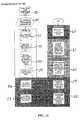
- FIG. 1is a block schematic diagram showing one embodiment of the present invention
- FIG. 2is a block schematic diagram showing an example of a manufacturing process system including the present invention
- FIG. 3is an example of typical screen images required in a prior art system for configuring or changing the processing or manufacturing system
- FIGS. 4 through 11show screen images for various embodiments of the invention for initially configuring a chemical processing system as an example of one use of the present invention
- FIG. 12shows a flowchart of a method for changing the configuration of the illustrative chemical system for an embodiment of the invention
- FIGS. 13 through 15show screen images illustrating the ease with which a user can implement the invention, add a tool, and select chemicals in configuring the illustrative chemical processing system
- FIGS. 16 through 20show screen images illustrating the ease with which a user can implement the invention to delete a tool.
- the present inventionprovides a Configurable Control System (CCS) for permitting users of a manufacturing process system to both configure and reconfigure their system without changing the system software.
- CCSConfigurable Control System
- Operation of the various embodiments of the present inventionarc illustrated in association with a chemical processing system typically used by solid-state device or semiconductor manufacturers, for permitting such users to quickly add, modify, delete components, and change control signals in the associated processing system in accordance with desired changes in the associated chemical delivery network, all without requiring changes in the software.
- the various embodiments of the inventionpermit such changes to be made in the control system without requiring downtime in operating the chemical processing system.
- the Configurable Control System (CCS) of the present inventionincludes a chemical monitoring server 1 (CMS server), and a programmable logic controller 8 (PLC).
- CMS server 1is typically a personal computer, which is loaded with a database and graphical user interface software program, and a Supervisory Control And Data Acquisition (SCADA) application 11 software program.
- SCADASupervisory Control And Data Acquisition
- a userenters configuration information into a forms based graphical user interface (GUI) displayed as screen images on a computer monitor (not shown), whereby the data is entered into the configuration tool 2 .
- the configuration tool 2automatically generates configuration databases in a database file 4 containing data tables.
- the CCSalso includes a programmable logic controller (PLC) 8 that is programmed via a PLC application 9 .
- PLCprogrammable logic controller
- the configuration databases 4include a database for each of the SCADA application 11 , and PLC application 9 .
- the CMS server 1deploys changes and auto-generates graphics and alarms based on the processing system as defined through the configuration tool 2 .
- the PLC application 9assigns 10 and logic based on the process system defined through the configuration tool 2 via the established configuration data file 4 .
- a userAfter entering information into the configuration tool 2 , for use of screen images, a user then opens the SCADA software program, followed by opening a deployment tool 3 from the SCADA application 11 software main page. Through the use of screen images providing the user interface relative to the deployment tool 3 , a user can then proceed to update a SCADA configuration database 5 , and a PLC data array or database 10 . As shown further in FIG. 1, a download application with customized script 7 is utilized for downloading the database from the deployment tool 3 to the PLC data array 10 .
- the deployment tool 3updates the SCADA configuration database 5 with any changes made by the user via the configuration tool 2 .
- the SCADA application 11automatically responds by updating the SCADA display software 6 based upon the updated SCADA configuration database 5 .
- the deployment tool 3also downloads the PLC configuration data from database 4 to the PLC 8 , as previously described.
- the PLC 8is provided by an Allen-Bradley Control Logix Processor.
- a standard driversuch as a Rockwell Automation RSLinx is used for converting the configuration information in the PLC database 10 into an array format that can be read by the PLC 8 .
- the SCADA application 11download application 7 , and the application for configuration tool 2 and its database 4 do not have to be loaded onto the same PC.
- the personal computer providing the CMS server 1also represents a programmable Human Machine Interface (HMI), or Man Machine Interface (MMI).
- HMIHuman Machine Interface
- MMIMan Machine Interface
- the configuration databases 4 and GUI programare used for creating the databases for both the SCADA application 11 , and PLC application 9 .
- the construction of the PLC data array 10enables the RSLinx to efficiently download data from the deployment tool 3 to the PLC 8 .
- graphical user interfacespermit a user to define the physical and logical configuration of a manufacturing process system, for example that consists of a plurality of interconnected devices, tools, controllers, and so forth.
- a chemical processing systemtypically includes chemical distribution modules, blending modules, collection modules, valve boxes, programmable logic controllers, field IO panels, process tools, piping to carry and deliver various chemicals from supply to use points, interface panels, computer displays, tanks for holding various chemical products, and so forth.
- the configuration tool 2can be programmed in a variety of software development environments and languages including Web-based languages for providing the desired functionality provided by the present invention.
- the configuration tool 2is a Microsoft Access based-software application, provided by Microsoft Corporation.
- the configuration database 4 created by the configuration tool 2in the preferred embodiment is a Microsoft Access based software for describing the configuration of the associated manufacturing process system, in this example, a chemical system.
- the configuration database file 4contains variables that are shown below for the illustrated system that are read by SCADA application 11 , and programmable logic controller (PLC) application 9 .
- the configuration database file 4can also be provided by other software, such as extensible markup language (XML) for communicating over computer networks.
- XMLextensible markup language
- the deployment tool 3is a SCADA software application for downloading data from the configuration file 4 as previously described.
- the deployment tool 3is based upon Cimplicity software provided by General Electric Corporation.
- the SCADA application 11in the preferred embodiment is also GE Cimplicity-based software.
- the CMS server 1is programmed to monitor the status of the associated system, and provides the primary human/machine interface for users or operators of the associated processing system.
- the SCADA application 11can be developed for any manufacturing process system applicable for use with the present invention.
- the PLC application 9is a software application that receives data from the configuration file 4 for defining the objects and logic of the associated system, the chemical system in this example.
- Allen-Bradley software(provided by Allen-Bradley Corporation) is used for programming the associated Allen-Bradley programmable logic controller(s) 8 .
- the chemical processing systemincludes the CCS configuration tool 2 , CMS server 1 , and a single or redundant PLC 8 (shown redundantly with PLCs 8 A and 8 B), and other elements of the present invention as previously described.
- SCADA application program 11is used for programming the CMS server 1 .
- PLC application program 9is utilized for the PLC 8 .
- the illustrative components of the chemical processing systemalso include chemical distribution modules 12 , IO controllers 14 , a tool 18 , and valve box 16 .
- the network designsubstantially eliminates downtime by permitting the addition of dispenser and blender modules, for example, without interrupting operation of the existing system.
- a redundant PLC controller 8also known as a data concentrator, controls the distribution system.
- the controllers 14are jointly operative for managing the signals and logic required to safely deliver chemical products to the processing tool 18 , in this example.
- the SCADA application 11provides monitoring only, and is not associated with controlling the delivery of chemical products.
- the tedious coding required in the prior artis substantially eliminated.
- the CCS system of the present inventionmust be initialized prior to use.
- a useroperates a GUI, for example, for bringing up a Main Select Screen 32 as shown in FIG. 4.
- a userwill first address the pull-down screen for the “Object,” and in this example select “Room” from the Object Menu. Following this selection, the user then uses the pull-down menu for the “Action” entry, and in this example selects “Add” followed by selecting or pushing “Next.”
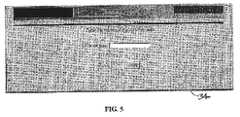
- the useris then shown a Room Add Screen Image 34 , as shown in FIG. 5 .
- the userthen types in the desired Room name, and presses finish.
- the useris next automatically presented the Main Select Screen 32 of FIG. 4 .
- the useruses the pull-down menu from the “Object” and selects a desired chemical system.
- the useraddresses the pull-down menu for “Action” and selects add, followed by selecting “Next.”
- the present CCSresponds by presenting the user with screen image 36 (see FIG. 6) for “Chemical System-Add.”
- the usertypes in the desired chemical name, and chemical room, followed by pressing “Finish” (note that wherever press or pressing is indicated, this is typically accomplished by using an associated computer mouse or touch screen).
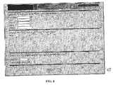
- the CCS of the present inventionautomatically returns the user to the screen image 32 for the Main Select Screen (see FIG. 4 ).
- the useraddresses the Object pull-down menu and selects FIOP (Field IO Panel), and from the Action pull-down selects Add followed by pressing Next.
- the CCSresponds by presenting the user with a screen image 38 (see FIG. 7) for Field IO Panel—Add.
- the userthen types in a FIOP name, addresses a pull-down menu for selecting a LAN (Local Area Network), and uses a pull-down menu for selecting a “Node.” After making these selections, the user then presses Finish.
- the useris automatically returned back to the main select screen 32 of FIG. 4 .
- the useraddresses the pull-down menu for Object, and selects a desired CDM (Chemical Distribution Module), addresses the pull-down menu for Action, and selects Add, followed by pushing Next.
- CDMComputer Distribution Module
- the CCSprovides screen image 40 , CDM-Add, whereby the user addresses the associated pull-down menus for selecting a chemical, desired type of CDM 12 (Chemical Distribution Module), and IP address, followed by typing in the name for the selected CDM 12 , and presses Finish.
- the CCSdisplays pull-down menus for permitting the user to choose a desired type of Signal, an applicable FIOP, an appropriate Slot, and Point.
- the usermust also use the pull-down menu to select or choose the supply and toggle information for the newly added CDM 12 .
- the user presses Finishthe CCS responds by displaying an Assign IO screen display permitting the user to choose a spare IO and press Finish.
- the CCSresponds by automatically returning the display to the Main Select Screen 32 (see FIG. 4 ).
- the useraddresses the pull-down for Object to select a valve box, followed by an address and a pull-down menu for Action and selecting Add, followed by pressing Next.
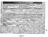
- the CCSresponds by displaying screen image 42 for Valve Box-Add (see FIG. 9 ).
- the userthen enters data either by typing in the blank data fields or utilizing the associated pull-down menus where applicable, for providing all of the information, and then presses Next.
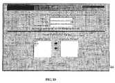
- the CCSresponds by displaying screen image 44 for Tool-Add (see FIG. 10 ).
- the userthen must type in the tool name in the appropriate data field, select the Tool Type from the associated pull-down menu in the data field, and optionally type in a Tool Location.
- the usermust also press the appropriate arrow keys to move the chemicals to the “Chems” for the associated Toolbox, followed by pressing Next.
- the useris next presented with a screen image for an IO Choice Screen (not shown), addresses the screen for choosing a spare IO, followed by the user pressing Finish.
- the CCSresponds by displaying the Main Select Screen 32 of FIG. 4, whereby the user uses the appropriate pull-down menus for selecting a valve box from Object, selecting Add from Action, followed by pushing Next.
- the useris next presented with a screen image 46 to permit the user to select a valve box to feed a tool, the selection being made by filling in the blank fields utilizing associated pull-down menus.
- the CCSresponds to the user pressing Next, by providing a new image screen (not shown) for permitting user to select a FIOP and module for a tool ready Signal.
- FIG. 12shows steps 50 through 62 for permitting a user to easily make a desired change in the illustrative chemical system. Steps 50 through 62 demand very little of the user, as will be shown.
- a useraddresses the main menu 32 of FIG. 4 for in this example pulling up the screen image 70 (see FIG. 13) for “Tool Add 1 : Form,” after the user types in the appropriate tool name, uses the pull-down menu to insert the Tool Type, and may optionally include the tool location.
- the userpushes on the appropriate ones of the arrows for selecting chemicals for the indicated tool. Following this, the user presses Next.
- the CCSresponds by presenting the screen image 72 (see FIG. 14) for “Tool Add 2 : Form.” The user then addresses the various pull-down menus of the data field shown for assigning IO where required, followed by pressing Finish.
- the CCSresponds by bringing up screen image 74 for “Deployment Tool.CIM, as shown in FIG. 15 .
- the usersimply employs a computer mouse for addressing the desired toggle buttons to deploy the changes previously made.
- the present human/machine interfacehas been partially illustrated above in association with FIGS. 4 through 15.
- the illustrated use of a main select screen with associated pull down menus, and associated other screen images with appropriate pull down menus and data fields for entry of dataare utilized to permit a user to easily configure and control the associated manufacturing process system.
- the illustrated screen imagescan be developed in the present invention for facilitating many different functions.
- These functionscan include adding or deleting a tool, adding or deleting a chemical to and from a tool, respectively, renaming a tool, adding or deleting a valve box, adding or deleting a FIOP (Field IO Panel), adding or deleting a tool type, adding or deleting a valve box type, adding or deleting an auxiliary signal, adding or deleting an FMS (Factory Monitoring System), adding or deleting a CDM (Chemical Distribution Module) and so forth.
- FMSFactory Monitoring System
- CDMCode Division Multiple Distribution Module
- the configuration tool 2 as illustrated for use in a chemical processing systempermits a user to add, edit, and delete system objects. These objects may include chemical rooms, dispenser or blender systems, valve boxes, points of use and auxiliary signals. Also, it permits the user to configure signal locations using an IO Anywhere system, for placing system IO signals in any point in the control system to provide flexibility, and limit construction and hardware costs. Also, it permits the user to configure signals required for each system component, such as defining a valve box as having a specific number of leak sensors. Also, it provides the user the capability to configure system operational logic, such as the signals required for activating tools, and supply valves, for example. Also, it permits the user to configure safety logic based on the particular requirements of the process system, such as the isolation or shutdown protocol in the event of a valve box leak.
- FIGS. 16 through 20illustrate the process of making a change to the Configurable Control System for deleting a tool, in this example.
- FIG. 16shows the SCADA Distribution Status screen located on the PC.
- the CDM in FIG. 16indicates that four tools (T 1 , T 2 , T 3 and T 4 ) are initially connected to the CDM.
- the userdecides to modify the manufacturing equipment by eliminating a Tool from the manufacturing process, the user must begin at the Configuration Tool's Main Select Screen shown in FIG. 17 .
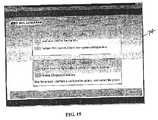
- the userselects Tool and Delete, and then selects “Next” to continue as shown in FIG. 18 .
- the next screen that appearsis the Tool-Delete screen shown in FIG. 18 .
- the userselects the Tool to be deleted.
- the userselects Tool 4 (T 4 ) for deletion from the Configurable Control System.
- the userthen presses Finish to implement the updates to the Configuration Databases.
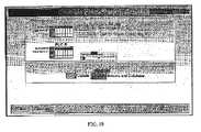
- the useraccesses the Deployment Tool from the SCADA Application.
- the Deployment Tool Screen(FIG. 19 )
- the userdownloads new data to the PLCs 8 A, 8 B, and updates the SCADA display and database of CMS server 1 .
- PLC 8 Ais updated, the user switches control to PLC 8 A, then updates PLC 8 B.
- the useralso updates the SCADA display and database by pressing the corresponding button as shown in FIG. 19 .
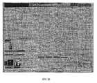
- FIG. 20shows the updated SCADA Distribution SCADA Screen. As expected, T 4 is deleted and the connection is now a spare to the CDM.
- the CCSis composed of a plurality of components, that combined create a user configurable Man Machine Interface and process control of the illustrated Chemical Distribution System 13 .
- Ethernet Communicationsis provided between PLC 8 and PC included in CMS server 1 , in this example.
- the basic concept of the systemis to create a configuration of the control of the chemical distribution system and store the configuration in Configuration Databases 4 .
- Information stored in the databases 4is placed there in a very structured and unique format.
- the database 4is segregated into the PLC database 10 and the SCADA database 5 .
- the PLC database 10contains tables laid out in a manner to match the memory arrays laid out in the PLC 8 .
- these database tablesare populated with Input/Output point location and or/that the logic for this particular logic table is enabled and an index number for how many times the logic should be performed.
- Other informationsuch as timer presets are also stored in tables that match the memory arrays in the PLC 8 .
- the PLC application software 9is designed around a maximum build of the configurable control system (the largest number of distributed input/output points) and the maximum build of objects to be controlled (points of use, valve box leak points). By assigning a unique number to each possible i/o point in the PLC 8 control system, the PLC database 10 becomes a match for the logic arrays in the PLC application software 9 .
- the download tool 7uses RSLinx and DDE commands, moves information from each array in the PLC Database 10 array into the PLC application program 9 , one after the other, and populates the PLC application program logic array with the information stored in the database 10 .
- the Download Tool 7loads the logic array to the offline PLC 8 A, for example, and when the logic is to become active, the control of the distributed I/O in the system is switched from the active PLC 8 A to the backup PLC 8 B, and the new control logic takes over, as previously mentioned.
- the once active PLC 8 Ais now backup and information is loaded to this PLC 8 A via the download tool 7 .
- CDA'sare 2-dimensional double integer arrays “DINT'S” that contain the reference location of the real world input, output, and internal variables stored in a Main Bit Array.
- the CDA'suse the reference location to look up the state of the input or output or internal bit of the Main Bit Array and then use the state, either low “0” or high “1” to perform logic.
- Configuration Download arraysare 2-dimensional but with varying lengths depending upon the logic that must be performed to determine the desired result.
- the design of a CDAis 2-dimension DINT Array which has a primary dimension index and a secondary dimension index.
- the primary indexis used in the Data Concentrator Logic as the index in a For/Next Loop instruction.
- the secondary dimension indexcontains the reference location of the input or output or internal bit from the Main Bit array.
- the primary dimensionwill be referred to as “index” and the secondary dimension will be known as the coefficient.
- Temp0is the local variable name used in the Data Concentrator PLC 8 logic that references coefficent0 in the Configuration Download Array. Temp#'s range from 0 on up to 150 for some CDA's. Temp Row in the CDA example has the Temp# for each column or coefficient used in the logic. The coefficient 0 . . . 150 contains the location of the real world input or output.
- Not Selectedis the reference location in the MA.Bit array that the Configuration Tool stores in the coefficient where the coefficient in the logic is not selected or required or used. If the coefficient reference location is 0, then the state at location 0 in the MA.Bit array is always 0. If the coefficient location is 1, then the state at location 1 in the MA.Bit array is always 1.
- a Coefficient value of 7900is the reference location of a “trash output” that will never be examined. Since the logic is different for each type of CDA, the not selected row shows the coefficient value that should be used to “Not select” the option. The placement of 0 or 1 or 7900 into the CDA is determined by the Configuration Tool software.
- the SCADA Application Software 11also uses predefined database tables that are populated with configuration data of the SCADA application. Since both the SCADA application software 11 and the Configuration Tool Application software and the Configuration Database 4 reside on a Personal Computer 9 (not shown), the SCADA application 11 directly access the database 4 to create objects and animation for viewing process operation. The only need for the Download Tool is to update the SCADA tag database.
- the SCADA application 11is centered upon a linked series of viewable screens, pre-populated with the maximum number of objects.
- the objects on the SCADA screensremain in an off state unless the Configuration Tool software animates them.
- the enabling of the object and the creation of the object tagis derived from the Configuration Tool database 4 .
- the SCADA application software 11gathers its animation data from the Configuration Database 4 and activates the objects on the screen of the computer monitor (not shown).
- the SCADA tagsare a set of addresses for I/O points that reside in the PLC 8 .
- the SCADA softwareuses RSLinx or other communication OPC drivers to communicate to the PLC and determine the status of the SCADA tag. Animation then occurs based upon the state of the tag.
- the SCADA applicationusing the Configuration database creates an tag containing the i/o point address, assigns it to animate the SCADA object for a valve box leak point, communicates via RSLinx on the state of the tag (either on or off) and animates it accordingly. This is done for all the objects associated with the screen.
- the Configurable Control System of the present inventionpermits a user to easily configure, and make changes to a manufacturing process system, without requiring a programmer to change the software.
- the CCSpermits a user to readily add to, delete from, rename, view, or create Objects in the associated manufacturing process system.
- the effect of the present inventionis to provide a user with a “plug and play” environment for the user's manufacturing process.
Landscapes
- Engineering & Computer Science (AREA)
- Physics & Mathematics (AREA)
- General Physics & Mathematics (AREA)
- Automation & Control Theory (AREA)
- Human Computer Interaction (AREA)
- Manufacturing & Machinery (AREA)
- Stored Programmes (AREA)
- Programmable Controllers (AREA)
Abstract
Description
| Temp | 0 | 1 | 2 | ||
| Not Selected | 1 | 0 | 7900 | ||
| Index | coefficient0 | coefficient1 | coefficient2 | ||
| 1 | |||||
| 2 | |||||
| 3 | |||||
| Max number | |||||
Claims (20)
Priority Applications (9)
| Application Number | Priority Date | Filing Date | Title |
|---|---|---|---|
| US10/460,794US6799080B1 (en) | 2003-06-12 | 2003-06-12 | Configurable PLC and SCADA-based control system |
| CNB2003101142406ACN100552576C (en) | 2003-06-12 | 2003-11-05 | Programmable logic controllers and control systems based on supervisory control and data acquisition |
| EP04776056AEP1631868A1 (en) | 2003-06-12 | 2004-05-20 | Configurable plc and scada-based control system |
| KR1020117024959AKR101105498B1 (en) | 2003-06-12 | 2004-05-20 | Configurable plc and scada-based control system |
| JP2006533233AJP4908219B2 (en) | 2003-06-12 | 2004-05-20 | Configurable PLC and SCADA based control system and method |
| PCT/US2004/015785WO2005008349A1 (en) | 2003-06-12 | 2004-05-20 | Configurable plc and scada-based control system |
| KR1020057023881AKR20060012327A (en) | 2003-06-12 | 2004-05-20 | Configurable PLC and SCDA Based Control System |
| TW093115162ATWI342990B (en) | 2003-06-12 | 2004-05-27 | Configurable plc and scada-based control system |
| IL172505AIL172505A (en) | 2003-06-12 | 2005-12-12 | Configurable plc and scada-based control system |
Applications Claiming Priority (1)
| Application Number | Priority Date | Filing Date | Title |
|---|---|---|---|
| US10/460,794US6799080B1 (en) | 2003-06-12 | 2003-06-12 | Configurable PLC and SCADA-based control system |
Publications (1)
| Publication Number | Publication Date |
|---|---|
| US6799080B1true US6799080B1 (en) | 2004-09-28 |
Family
ID=32990960
Family Applications (1)
| Application Number | Title | Priority Date | Filing Date |
|---|---|---|---|
| US10/460,794Expired - LifetimeUS6799080B1 (en) | 2003-06-12 | 2003-06-12 | Configurable PLC and SCADA-based control system |
Country Status (8)
| Country | Link |
|---|---|
| US (1) | US6799080B1 (en) |
| EP (1) | EP1631868A1 (en) |
| JP (1) | JP4908219B2 (en) |
| KR (2) | KR20060012327A (en) |
| CN (1) | CN100552576C (en) |
| IL (1) | IL172505A (en) |
| TW (1) | TWI342990B (en) |
| WO (1) | WO2005008349A1 (en) |
Cited By (47)
| Publication number | Priority date | Publication date | Assignee | Title |
|---|---|---|---|---|
| US20040260404A1 (en)* | 2003-06-23 | 2004-12-23 | Russell Thomas C. | Method and apparatus for self-configuring supervisory control and data acquisition (SCADA) system for distributed control |
| US20050005093A1 (en)* | 2003-07-01 | 2005-01-06 | Andrew Bartels | Methods, systems and devices for securing supervisory control and data acquisition (SCADA) communications |
| US20050097144A1 (en)* | 2003-11-04 | 2005-05-05 | Taiwan Semiconductor Manufacturing Co. | Performance tuning at CM loader program while replicating EQP list for IBM SiView |
| US20060168573A1 (en)* | 2005-01-14 | 2006-07-27 | Clark William A | Method and apparatus for building an electronic product |
| US20060212855A1 (en)* | 2005-03-16 | 2006-09-21 | Bournas Redha M | Methods, systems and computer program products for implementing production processes |
| US20070019641A1 (en)* | 2005-07-22 | 2007-01-25 | Rockwell Automation Technologies, Inc. | Execution of industrial automation applications on communication infrastructure devices |
| US20070162957A1 (en)* | 2003-07-01 | 2007-07-12 | Andrew Bartels | Methods, systems and devices for securing supervisory control and data acquisition (SCADA) communications |
| US20080103737A1 (en)* | 2006-10-31 | 2008-05-01 | Yoon Jong-Su | Simulation system for facts connected online to scada system |
| US20080109889A1 (en)* | 2003-07-01 | 2008-05-08 | Andrew Bartels | Methods, systems and devices for securing supervisory control and data acquisition (SCADA) communications |
| US20080127065A1 (en)* | 2006-08-24 | 2008-05-29 | Bryant William K | Devices, systems, and methods for configuring a programmable logic controller |
| US7526794B2 (en) | 2005-09-30 | 2009-04-28 | Rockwell Automation Technologies, Inc. | Data perspectives in controller system and production management systems |
| US20090287321A1 (en)* | 2003-02-18 | 2009-11-19 | Fisher-Rosemount Systems, Inc. | Configuration system using security objects in a process plant |
| US20100039952A1 (en)* | 2008-08-13 | 2010-02-18 | Christian Lenz | System for monitoring, control and data acquisition of technical processes |
| US20100114392A1 (en)* | 2008-11-06 | 2010-05-06 | Mark Lancaster | Real-Time Power Line Rating |
| US20100146087A1 (en)* | 2009-11-30 | 2010-06-10 | General Electric Wind Energy & Energy Services | Dynamic installation and uninstallation system of renewable energy farm hardware |
| US20100241252A1 (en)* | 2009-03-17 | 2010-09-23 | Foxnum Technology Co., Ltd. | Parameter setting system and method for programmable logic controller |
| WO2010098835A3 (en)* | 2009-02-24 | 2010-10-21 | Means Stephen R | Well test system |
| US20100312407A1 (en)* | 2006-10-18 | 2010-12-09 | Siemens Aktiengesellschaft | Method and system for controlling an electrical installation |
| US20120116543A1 (en)* | 2009-09-28 | 2012-05-10 | Toshiba Mitsubishi-Electric Industrial Systems Corporation | Plant control system |
| US20120143381A1 (en)* | 2010-11-15 | 2012-06-07 | Justin Lawyer | Apparatus and methods for controlling a habitat environment |
| US20130304248A1 (en)* | 2012-05-11 | 2013-11-14 | Artis Gmbh | Method and Apparatus for Automated Configuration of a Monitoring Function of a Machine Tool |
| US20130339497A1 (en)* | 2012-06-13 | 2013-12-19 | Schneider Electric Industries, SAS | Configuring devices in a network |
| CN103580928A (en)* | 2013-11-19 | 2014-02-12 | 北京恒泰实达科技股份有限公司 | System and method for visually controlling and operating devices |
| US20140316540A1 (en)* | 2013-03-08 | 2014-10-23 | Bosko Loncar | Method for producing plc and hmi tag database and system |
| US20150051726A1 (en)* | 2013-08-14 | 2015-02-19 | Artis Gmbh | Method and Apparatus for an Automated Configuration of a Monitoring Function of an Industrial Robot |
| EP2921920A1 (en) | 2014-01-30 | 2015-09-23 | Jean-Pierre Petit | Method for implementing an automation system |
| US9395714B2 (en) | 2012-10-25 | 2016-07-19 | Mitsubishi Electric Corporation | System construction support tool and system |
| JP2017027211A (en)* | 2015-07-17 | 2017-02-02 | 東芝三菱電機産業システム株式会社 | Plant control system |
| EP3185126A1 (en)* | 2015-12-21 | 2017-06-28 | Invensys Systems, Inc. | Monitoring application states for depolyment during runtime operations |
| US20170249745A1 (en)* | 2014-05-21 | 2017-08-31 | Millennium Three Technologies, Inc. | Fiducial marker patterns, their automatic detection in images, and applications thereof |
| US20180088541A1 (en)* | 2015-03-27 | 2018-03-29 | Bühler AG | Adaptive cross plant control and steering system, and corresponding method thereof |
| US20180231950A1 (en)* | 2017-02-13 | 2018-08-16 | Omron Corporation | Monitoring method, monitoring module, and mobile terminal for monitoring programmable logic controller |
| CN108845548A (en)* | 2018-07-04 | 2018-11-20 | 深圳库博能源科技有限公司 | A kind of DCS and distribution method realizing the distribution of IO hardwire based on software configuration |
| WO2018236714A1 (en) | 2017-06-23 | 2018-12-27 | Honeywell International Inc. | EFFICIENT METHOD AND SYSTEM FOR AUTOMATICALLY GENERATING DATA POINTS IN A SCADA SYSTEM |
| US10205307B2 (en) | 2010-03-23 | 2019-02-12 | Southwire Company, Llc | Power line maintenance monitoring |
| US10216166B2 (en) | 2012-01-06 | 2019-02-26 | General Electric Company | Apparatus and method for third party creation of control logic |
| US10231304B2 (en) | 2013-02-20 | 2019-03-12 | Current USA, Inc. | Habitat control system |
| US10235853B2 (en) | 2016-06-20 | 2019-03-19 | General Electric Company | Interface method and apparatus for alarms |
| US10444724B2 (en) | 2016-06-20 | 2019-10-15 | General Electric Company | Interface method and apparatus |
| US10455667B2 (en) | 2013-02-20 | 2019-10-22 | Current-Usa, Inc. | Lighting control systems |
| US10569967B2 (en) | 2016-12-13 | 2020-02-25 | Mark Rolfes | Integrated control systems and methods |
| US20200064992A1 (en)* | 2017-04-13 | 2020-02-27 | Mitsubishi Electric Corporation | Display screen generation apparatus, factory automation system, and display screen generation method |
| WO2020041820A1 (en)* | 2018-08-28 | 2020-03-05 | Peng Choo | Improved control and development web platform |
| CN113093686A (en)* | 2021-04-14 | 2021-07-09 | 宁波和利时智能科技有限公司 | SCADA-based automatic configuration modeling method and related device |
| CN114610290A (en)* | 2022-05-09 | 2022-06-10 | 北京东方融创信息技术有限公司 | Digital intelligent industrial configuration system |
| US20230161313A1 (en)* | 2020-05-12 | 2023-05-25 | Datumpin Ltd | Control system performance tracking apparatus and method |
| US11843266B2 (en) | 2021-02-02 | 2023-12-12 | Honeywell International, Inc. | Dynamic non-linear optimization of a battery energy storage system |
Families Citing this family (21)
| Publication number | Priority date | Publication date | Assignee | Title |
|---|---|---|---|---|
| EP1913506A4 (en)* | 2005-07-11 | 2008-08-13 | Brooks Automation Inc | Intelligent condition monitoring and fault diagnostic system for predictive maintenance |
| US7558703B2 (en)* | 2006-11-01 | 2009-07-07 | Abb Research Ltd. | Electrical substation monitoring and diagnostics |
| US8175732B2 (en) | 2006-12-22 | 2012-05-08 | Harris Stratex Networks Operating Corporation | Manufacturing system and method |
| US8712567B2 (en) | 2006-12-22 | 2014-04-29 | Aviat U.S., Inc. | Manufactured product configuration |
| US8041444B2 (en) | 2006-12-22 | 2011-10-18 | Harris Stratex Networks Operating Corporation | Intelligent production station and production method |
| US7894460B2 (en)* | 2007-07-26 | 2011-02-22 | Air Liquide Large Industries U.S. Lp | Programmable logic controller protocol converter |
| JP4852070B2 (en)* | 2008-06-16 | 2012-01-11 | 三菱電機株式会社 | Plant monitoring and control system |
| CN102096399B (en)* | 2010-12-16 | 2013-10-09 | 上海雄华数码科技有限公司 | Embedded energy data acquisition unit |
| EP2490086B1 (en)* | 2011-02-16 | 2013-10-02 | Siemens Aktiengesellschaft | Method for operating an automation system and computer program operating by the method |
| TWI420389B (en)* | 2011-04-29 | 2013-12-21 | Delta Electronics Inc | Human machine interface device and interface integration method thereof |
| CN104871098B (en)* | 2012-12-20 | 2017-06-16 | 三菱电机株式会社 | Control system, program dispensing device, certificate server, program protection method, program sending method |
| DE102013208629A1 (en)* | 2013-05-10 | 2014-11-13 | Dr. Johannes Heidenhain Gmbh | Position measuring device |
| WO2016042602A1 (en)* | 2014-09-16 | 2016-03-24 | 三菱電機株式会社 | Programmable logic controller |
| KR101869233B1 (en)* | 2016-03-08 | 2018-06-20 | 주식회사 로제타텍 | Operating method of process management system for distributed programmable logic controllers adopting internet-of-things configuration |
| KR101873655B1 (en) | 2016-11-30 | 2018-07-02 | 엘에스산전 주식회사 | Method for displaying a monitoring screen |
| EP3669239B1 (en)* | 2017-09-19 | 2021-08-25 | Siemens Aktiengesellschaft | Apparatus and method for autonomously adding and removing of functionality in programmable logic controllers (plcs) |
| JP6996257B2 (en)* | 2017-11-27 | 2022-01-17 | オムロン株式会社 | Controls, control methods, and programs |
| JP6452922B1 (en)* | 2018-04-06 | 2019-01-16 | 三菱電機株式会社 | System construction support device, system construction support method, and system construction support program |
| EP3805878B1 (en)* | 2019-10-11 | 2022-06-15 | Siemens Aktiengesellschaft | Method for visualizing display data on a data display system and a data display system for visualizing display data |
| JP7131706B2 (en)* | 2019-11-26 | 2022-09-06 | 東芝三菱電機産業システム株式会社 | SCADA web HMI system |
| CN114647233B (en)* | 2022-05-18 | 2022-09-30 | 浙江国利网安科技有限公司 | PLC operation configuration monitoring method and device, storage medium and electronic equipment |
Citations (6)
| Publication number | Priority date | Publication date | Assignee | Title |
|---|---|---|---|---|
| US5396416A (en)* | 1992-08-19 | 1995-03-07 | Continental Controls, Inc. | Multivariable process control method and apparatus |
| US5504693A (en)* | 1993-07-13 | 1996-04-02 | Omni Flow Company, Inc. | Flow control system |
| US6411987B1 (en)* | 1998-08-21 | 2002-06-25 | National Instruments Corporation | Industrial automation system and method having efficient network communication |
| US6505247B1 (en)* | 1998-08-21 | 2003-01-07 | National Instruments Corporation | Industrial automation system and method for efficiently transferring time-sensitive and quality-sensitive data |
| US6643555B1 (en)* | 2000-10-10 | 2003-11-04 | Schneider Automation Inc. | Method and apparatus for generating an application for an automation control system |
| US20030220717A1 (en)* | 2002-05-22 | 2003-11-27 | Underwood Fred R. | Water treatment control system |
Family Cites Families (21)
| Publication number | Priority date | Publication date | Assignee | Title |
|---|---|---|---|---|
| US5225974A (en)* | 1990-10-30 | 1993-07-06 | Allen-Bradley Company, Inc. | Programmable controller processor with an intelligent functional module interface |
| JPH04273524A (en)* | 1991-02-28 | 1992-09-29 | Toshiba Corp | Automatic program generation device |
| JP2966966B2 (en)* | 1991-05-31 | 1999-10-25 | 株式会社東芝 | Redundant device for programmable controller |
| JP3136837B2 (en)* | 1993-06-03 | 2001-02-19 | 日産自動車株式会社 | Monitoring equipment for production equipment |
| JPH07152549A (en)* | 1993-11-29 | 1995-06-16 | Fuji Electric Co Ltd | How to develop plant software |
| JPH07191716A (en)* | 1993-12-27 | 1995-07-28 | Mitsubishi Electric Corp | Control device |
| JPH096430A (en)* | 1995-06-16 | 1997-01-10 | Toshiba Corp | Screen selection device |
| WO1997012301A1 (en)* | 1995-09-25 | 1997-04-03 | Siemens Aktiengesellschaft | Drafting method for industrial and building systems and computer-controlled planning system for use in said method |
| JPH1063312A (en)* | 1996-08-23 | 1998-03-06 | Toshiba Corp | Plant control program management device |
| JPH10340108A (en)* | 1997-06-06 | 1998-12-22 | Mitsubishi Electric Corp | Peripheral device for programmable logic controller |
| JPH1195819A (en)* | 1997-09-25 | 1999-04-09 | Fuji Electric Co Ltd | Programming device for programmable controller, connection method, and recording medium |
| JP3581538B2 (en)* | 1997-09-30 | 2004-10-27 | 日立エンジニアリング株式会社 | Program specification automatic generation support system |
| WO2000065361A1 (en)* | 1999-03-25 | 2000-11-02 | Fluor Corporation | Simulator cart |
| JP2001075791A (en)* | 1999-09-02 | 2001-03-23 | Digital Electronics Corp | Editor device and recording medium recording editor program |
| JP2001202298A (en)* | 2000-01-19 | 2001-07-27 | Toshiba Corp | Monitoring management device, site monitoring device, and computer-readable recording medium recording program |
| US6556956B1 (en)* | 2000-06-30 | 2003-04-29 | General Electric Company | Data acquisition unit for remote monitoring system and method for remote monitoring |
| EP1176482B1 (en)* | 2000-07-27 | 2004-12-22 | Abb Research Ltd. | Method and computer program for generating a regulation or control system |
| JP2002182739A (en)* | 2000-12-11 | 2002-06-26 | Toshiba Corp | Monitoring and control equipment |
| JP2002182889A (en)* | 2000-12-15 | 2002-06-28 | Digital Electronics Corp | Display device for control |
| WO2002101596A2 (en)* | 2001-06-13 | 2002-12-19 | Robert Bosch Gmbh | Method and system for assisting in the planning of manufacturing facilities |
| US7367028B2 (en)* | 2001-08-14 | 2008-04-29 | National Instruments Corporation | Graphically deploying programs on devices in a system |
- 2003
- 2003-06-12USUS10/460,794patent/US6799080B1/ennot_activeExpired - Lifetime
- 2003-11-05CNCNB2003101142406Apatent/CN100552576C/ennot_activeExpired - Lifetime
- 2004
- 2004-05-20EPEP04776056Apatent/EP1631868A1/ennot_activeWithdrawn
- 2004-05-20KRKR1020057023881Apatent/KR20060012327A/ennot_activeCeased
- 2004-05-20KRKR1020117024959Apatent/KR101105498B1/ennot_activeExpired - Lifetime
- 2004-05-20JPJP2006533233Apatent/JP4908219B2/ennot_activeExpired - Lifetime
- 2004-05-20WOPCT/US2004/015785patent/WO2005008349A1/enactiveApplication Filing
- 2004-05-27TWTW093115162Apatent/TWI342990B/ennot_activeIP Right Cessation
- 2005
- 2005-12-12ILIL172505Apatent/IL172505A/enactiveIP Right Grant
Patent Citations (6)
| Publication number | Priority date | Publication date | Assignee | Title |
|---|---|---|---|---|
| US5396416A (en)* | 1992-08-19 | 1995-03-07 | Continental Controls, Inc. | Multivariable process control method and apparatus |
| US5504693A (en)* | 1993-07-13 | 1996-04-02 | Omni Flow Company, Inc. | Flow control system |
| US6411987B1 (en)* | 1998-08-21 | 2002-06-25 | National Instruments Corporation | Industrial automation system and method having efficient network communication |
| US6505247B1 (en)* | 1998-08-21 | 2003-01-07 | National Instruments Corporation | Industrial automation system and method for efficiently transferring time-sensitive and quality-sensitive data |
| US6643555B1 (en)* | 2000-10-10 | 2003-11-04 | Schneider Automation Inc. | Method and apparatus for generating an application for an automation control system |
| US20030220717A1 (en)* | 2002-05-22 | 2003-11-27 | Underwood Fred R. | Water treatment control system |
Cited By (81)
| Publication number | Priority date | Publication date | Assignee | Title |
|---|---|---|---|---|
| US20090287321A1 (en)* | 2003-02-18 | 2009-11-19 | Fisher-Rosemount Systems, Inc. | Configuration system using security objects in a process plant |
| US7971052B2 (en)* | 2003-02-18 | 2011-06-28 | Fisher-Rosemount Systems, Inc. | Configuration system using security objects in a process plant |
| US20040260404A1 (en)* | 2003-06-23 | 2004-12-23 | Russell Thomas C. | Method and apparatus for self-configuring supervisory control and data acquisition (SCADA) system for distributed control |
| US20050005093A1 (en)* | 2003-07-01 | 2005-01-06 | Andrew Bartels | Methods, systems and devices for securing supervisory control and data acquisition (SCADA) communications |
| US20070162957A1 (en)* | 2003-07-01 | 2007-07-12 | Andrew Bartels | Methods, systems and devices for securing supervisory control and data acquisition (SCADA) communications |
| US20080109889A1 (en)* | 2003-07-01 | 2008-05-08 | Andrew Bartels | Methods, systems and devices for securing supervisory control and data acquisition (SCADA) communications |
| US20100058052A1 (en)* | 2003-07-01 | 2010-03-04 | Andrew Bartels | Methods, systems and devices for securing supervisory control and data acquisition (scada) communications |
| US20050097144A1 (en)* | 2003-11-04 | 2005-05-05 | Taiwan Semiconductor Manufacturing Co. | Performance tuning at CM loader program while replicating EQP list for IBM SiView |
| US20060168573A1 (en)* | 2005-01-14 | 2006-07-27 | Clark William A | Method and apparatus for building an electronic product |
| US20060212855A1 (en)* | 2005-03-16 | 2006-09-21 | Bournas Redha M | Methods, systems and computer program products for implementing production processes |
| US20070019641A1 (en)* | 2005-07-22 | 2007-01-25 | Rockwell Automation Technologies, Inc. | Execution of industrial automation applications on communication infrastructure devices |
| WO2007041026A3 (en)* | 2005-09-30 | 2009-06-18 | Rockwell Automation Tech Inc | Data perspectives in controller system and production management systems |
| US7526794B2 (en) | 2005-09-30 | 2009-04-28 | Rockwell Automation Technologies, Inc. | Data perspectives in controller system and production management systems |
| US20080127065A1 (en)* | 2006-08-24 | 2008-05-29 | Bryant William K | Devices, systems, and methods for configuring a programmable logic controller |
| US8898633B2 (en)* | 2006-08-24 | 2014-11-25 | Siemens Industry, Inc. | Devices, systems, and methods for configuring a programmable logic controller |
| US8219255B2 (en)* | 2006-10-18 | 2012-07-10 | Siemens Aktiengesellschaft | Method and system for controlling an electrical installation |
| US20100312407A1 (en)* | 2006-10-18 | 2010-12-09 | Siemens Aktiengesellschaft | Method and system for controlling an electrical installation |
| US20080103737A1 (en)* | 2006-10-31 | 2008-05-01 | Yoon Jong-Su | Simulation system for facts connected online to scada system |
| US8249836B2 (en)* | 2006-10-31 | 2012-08-21 | Korea Electric Power Corporation | Simulation system for FACTS connected online to SCADA system |
| US20100039952A1 (en)* | 2008-08-13 | 2010-02-18 | Christian Lenz | System for monitoring, control and data acquisition of technical processes |
| US8744790B2 (en) | 2008-11-06 | 2014-06-03 | Southwire Company | Real-time power line rating |
| US8386198B2 (en) | 2008-11-06 | 2013-02-26 | Southwire Company | Real-time power line rating |
| US20100114392A1 (en)* | 2008-11-06 | 2010-05-06 | Mark Lancaster | Real-Time Power Line Rating |
| WO2010098835A3 (en)* | 2009-02-24 | 2010-10-21 | Means Stephen R | Well test system |
| US8116888B2 (en)* | 2009-03-17 | 2012-02-14 | Foxnum Technology Co., Ltd. | Parameter setting system and method for programmable logic controller |
| US20100241252A1 (en)* | 2009-03-17 | 2010-09-23 | Foxnum Technology Co., Ltd. | Parameter setting system and method for programmable logic controller |
| US9020614B2 (en)* | 2009-09-28 | 2015-04-28 | Toshiba Mitsubishi-Electric Industrial Systems Corporation | Plant control system |
| CN102576223A (en)* | 2009-09-28 | 2012-07-11 | 东芝三菱电机产业系统株式会社 | Plant control system |
| US20120116543A1 (en)* | 2009-09-28 | 2012-05-10 | Toshiba Mitsubishi-Electric Industrial Systems Corporation | Plant control system |
| TWI407277B (en)* | 2009-09-28 | 2013-09-01 | Toshiba Mitsubishi Elec Inc | Factory control system |
| CN102576223B (en)* | 2009-09-28 | 2015-03-18 | 东芝三菱电机产业系统株式会社 | Equipment Control System |
| US7908348B2 (en) | 2009-11-30 | 2011-03-15 | General Electric Company | Dynamic installation and uninstallation system of renewable energy farm hardware |
| US20100146087A1 (en)* | 2009-11-30 | 2010-06-10 | General Electric Wind Energy & Energy Services | Dynamic installation and uninstallation system of renewable energy farm hardware |
| US10205307B2 (en) | 2010-03-23 | 2019-02-12 | Southwire Company, Llc | Power line maintenance monitoring |
| US20120143381A1 (en)* | 2010-11-15 | 2012-06-07 | Justin Lawyer | Apparatus and methods for controlling a habitat environment |
| US9166811B2 (en)* | 2010-11-15 | 2015-10-20 | Ecotech Marine, Llc | Apparatus and methods for controlling a habitat environment |
| US10412938B2 (en) | 2010-11-15 | 2019-09-17 | Ecotech Marine, Llc | Apparatus and methods for controlling a habitat environment |
| US11470825B2 (en) | 2010-11-15 | 2022-10-18 | Ecotech, Llc | Apparatus and methods for controlling a habitat environment |
| US10613506B2 (en) | 2012-01-06 | 2020-04-07 | General Electric Company | Apparatus and method for creating and presenting control logic |
| US10671044B2 (en) | 2012-01-06 | 2020-06-02 | GE Intelligent Platforms Inc. | Apparatus and method for synchronization of control logic of a controller via a network |
| US10996648B2 (en) | 2012-01-06 | 2021-05-04 | General Electric Company | Apparatus and method for third party creation of control logic |
| US10216166B2 (en) | 2012-01-06 | 2019-02-26 | General Electric Company | Apparatus and method for third party creation of control logic |
| US9733637B2 (en)* | 2012-05-11 | 2017-08-15 | Artis Gmbh | Method and apparatus for automated configuration of a monitoring function of a machine tool |
| US20130304248A1 (en)* | 2012-05-11 | 2013-11-14 | Artis Gmbh | Method and Apparatus for Automated Configuration of a Monitoring Function of a Machine Tool |
| US20130339497A1 (en)* | 2012-06-13 | 2013-12-19 | Schneider Electric Industries, SAS | Configuring devices in a network |
| US9395714B2 (en) | 2012-10-25 | 2016-07-19 | Mitsubishi Electric Corporation | System construction support tool and system |
| US10716178B2 (en) | 2013-02-20 | 2020-07-14 | Current USA, Inc. | Habitat control system |
| US10455667B2 (en) | 2013-02-20 | 2019-10-22 | Current-Usa, Inc. | Lighting control systems |
| US10231304B2 (en) | 2013-02-20 | 2019-03-12 | Current USA, Inc. | Habitat control system |
| US20140316540A1 (en)* | 2013-03-08 | 2014-10-23 | Bosko Loncar | Method for producing plc and hmi tag database and system |
| US9727033B2 (en)* | 2013-03-08 | 2017-08-08 | 2362738 Ontario Inc. | Method for producing PLC and HMI tag database and system |
| US20150051726A1 (en)* | 2013-08-14 | 2015-02-19 | Artis Gmbh | Method and Apparatus for an Automated Configuration of a Monitoring Function of an Industrial Robot |
| US9823648B2 (en)* | 2013-08-14 | 2017-11-21 | Artis Gmbh | Method and apparatus for an automated configuration of a monitoring function of an industrial robot |
| CN103580928A (en)* | 2013-11-19 | 2014-02-12 | 北京恒泰实达科技股份有限公司 | System and method for visually controlling and operating devices |
| CN103580928B (en)* | 2013-11-19 | 2017-06-16 | 北京恒泰实达科技股份有限公司 | A kind of system and method to equipment control visualized operation |
| EP2921920A1 (en) | 2014-01-30 | 2015-09-23 | Jean-Pierre Petit | Method for implementing an automation system |
| US10504231B2 (en)* | 2014-05-21 | 2019-12-10 | Millennium Three Technologies, Inc. | Fiducial marker patterns, their automatic detection in images, and applications thereof |
| US20170249745A1 (en)* | 2014-05-21 | 2017-08-31 | Millennium Three Technologies, Inc. | Fiducial marker patterns, their automatic detection in images, and applications thereof |
| US20180088541A1 (en)* | 2015-03-27 | 2018-03-29 | Bühler AG | Adaptive cross plant control and steering system, and corresponding method thereof |
| US10649414B2 (en)* | 2015-03-27 | 2020-05-12 | Bühler AG | Adaptive cross plant control and steering system, and corresponding method thereof |
| JP2017027211A (en)* | 2015-07-17 | 2017-02-02 | 東芝三菱電機産業システム株式会社 | Plant control system |
| EP3185126A1 (en)* | 2015-12-21 | 2017-06-28 | Invensys Systems, Inc. | Monitoring application states for depolyment during runtime operations |
| CN113835720A (en)* | 2015-12-21 | 2021-12-24 | 阿韦瓦软件有限责任公司 | Monitoring application state for deployment during runtime actions |
| US9703546B1 (en) | 2015-12-21 | 2017-07-11 | Schneider Electric Software, Llc | Monitoring application states for deployment during runtime operations |
| US10235853B2 (en) | 2016-06-20 | 2019-03-19 | General Electric Company | Interface method and apparatus for alarms |
| US10444724B2 (en) | 2016-06-20 | 2019-10-15 | General Electric Company | Interface method and apparatus |
| US10569967B2 (en) | 2016-12-13 | 2020-02-25 | Mark Rolfes | Integrated control systems and methods |
| US20180231950A1 (en)* | 2017-02-13 | 2018-08-16 | Omron Corporation | Monitoring method, monitoring module, and mobile terminal for monitoring programmable logic controller |
| US20200064992A1 (en)* | 2017-04-13 | 2020-02-27 | Mitsubishi Electric Corporation | Display screen generation apparatus, factory automation system, and display screen generation method |
| US10990262B2 (en)* | 2017-04-13 | 2021-04-27 | Mitsubishi Electric Corporation | Display screen generation apparatus, factory automation system, and display screen generation method |
| WO2018236714A1 (en) | 2017-06-23 | 2018-12-27 | Honeywell International Inc. | EFFICIENT METHOD AND SYSTEM FOR AUTOMATICALLY GENERATING DATA POINTS IN A SCADA SYSTEM |
| CN110914775A (en)* | 2017-06-23 | 2020-03-24 | 霍尼韦尔国际公司 | Efficient method and system for automatically generating data points in a SCADA system |
| CN108845548B (en)* | 2018-07-04 | 2021-01-05 | 深圳库博能源科技有限公司 | DCS and distribution method for realizing IO hard-wired distribution based on software configuration |
| CN108845548A (en)* | 2018-07-04 | 2018-11-20 | 深圳库博能源科技有限公司 | A kind of DCS and distribution method realizing the distribution of IO hardwire based on software configuration |
| WO2020041820A1 (en)* | 2018-08-28 | 2020-03-05 | Peng Choo | Improved control and development web platform |
| GB2593597A (en)* | 2018-08-28 | 2021-09-29 | Choo Peng | Improved control and development web platform |
| US12411470B2 (en)* | 2020-05-12 | 2025-09-09 | Datumpin Ltd | Control system performance tracking apparatus and method |
| US20230161313A1 (en)* | 2020-05-12 | 2023-05-25 | Datumpin Ltd | Control system performance tracking apparatus and method |
| US11843266B2 (en) | 2021-02-02 | 2023-12-12 | Honeywell International, Inc. | Dynamic non-linear optimization of a battery energy storage system |
| CN113093686A (en)* | 2021-04-14 | 2021-07-09 | 宁波和利时智能科技有限公司 | SCADA-based automatic configuration modeling method and related device |
| CN114610290A (en)* | 2022-05-09 | 2022-06-10 | 北京东方融创信息技术有限公司 | Digital intelligent industrial configuration system |
Also Published As
| Publication number | Publication date |
|---|---|
| EP1631868A1 (en) | 2006-03-08 |
| IL172505A0 (en) | 2006-04-10 |
| CN1577192A (en) | 2005-02-09 |
| KR20060012327A (en) | 2006-02-07 |
| TW200504559A (en) | 2005-02-01 |
| KR20110121728A (en) | 2011-11-08 |
| CN100552576C (en) | 2009-10-21 |
| TWI342990B (en) | 2011-06-01 |
| JP4908219B2 (en) | 2012-04-04 |
| WO2005008349A1 (en) | 2005-01-27 |
| JP2007504570A (en) | 2007-03-01 |
| KR101105498B1 (en) | 2012-01-13 |
| IL172505A (en) | 2011-04-28 |
Similar Documents
| Publication | Publication Date | Title |
|---|---|---|
| US6799080B1 (en) | Configurable PLC and SCADA-based control system | |
| JP6549748B2 (en) | Process control configuration method, process control configuration system, and software system | |
| CN109597376B (en) | System and method for supporting multi-language display view capabilities in a process control plant | |
| US6098116A (en) | Process control system including a method and apparatus for automatically sensing the connection of devices to a network | |
| US8185871B2 (en) | System for configuring a process control environment | |
| US5801942A (en) | Process control system user interface including selection of multiple control languages | |
| US5909368A (en) | Process control system using a process control strategy distributed among multiple control elements | |
| US5862052A (en) | Process control system using a control strategy implemented in a layered hierarchy of control modules | |
| US6032208A (en) | Process control system for versatile control of multiple process devices of various device types | |
| US5828851A (en) | Process control system using standard protocol control of standard devices and nonstandard devices | |
| US7020532B2 (en) | Methods and apparatus for control using control devices that provide a virtual machine environment and that communicate via an IP network | |
| US7747718B2 (en) | Control system apparatus, method for setting control system and setting program | |
| US7500597B2 (en) | Configurable interface configuration method and system using a remote interface | |
| EP2093638B1 (en) | Methods and apparatus to create process plant operator interfaces | |
| US20070260982A1 (en) | Runtime human-machine interface for process control having enhanced graphical views of detailed control information | |
| US20070239291A1 (en) | Runtime human-machine interface for process control having enhanced view hierarchy navigation controls | |
| CN101460991A (en) | Strategy editor human-machine interface | |
| JP2006302297A (en) | Control system setting apparatus, control system setting method and setting program | |
| US10558184B2 (en) | Weakly-typed dataflow infrastructure with standalone, configurable connections | |
| WO2007106085A1 (en) | Configurable human-machine interface configuration method and system using a remote interface |
Legal Events
| Date | Code | Title | Description |
|---|---|---|---|
| AS | Assignment | Owner name:BOC GROUP, INC., THE, NEW JERSEY Free format text:ASSIGNMENT OF ASSIGNORS INTEREST;ASSIGNORS:HYLDEN, MARK W.;ALEXANDER, BRAD ALAN;WICHMAN, CHRISTOPHER ALLEN;AND OTHERS;REEL/FRAME:014859/0514;SIGNING DATES FROM 20031007 TO 20031208 | |
| STCF | Information on status: patent grant | Free format text:PATENTED CASE | |
| AS | Assignment | Owner name:BOC EDWARDS, INC., MASSACHUSETTS Free format text:ASSIGNMENT OF ASSIGNORS INTEREST;ASSIGNOR:THE BOC GROUP, INC.;REEL/FRAME:019767/0251 Effective date:20070330 Owner name:BOC EDWARDS, INC.,MASSACHUSETTS Free format text:ASSIGNMENT OF ASSIGNORS INTEREST;ASSIGNOR:THE BOC GROUP, INC.;REEL/FRAME:019767/0251 Effective date:20070330 | |
| AS | Assignment | Owner name:EDWARDS VACUUM, INC., MASSACHUSETTS Free format text:CHANGE OF NAME;ASSIGNOR:BOC EDWARDS, INC.;REEL/FRAME:020654/0963 Effective date:20070920 Owner name:EDWARDS VACUUM, INC.,MASSACHUSETTS Free format text:CHANGE OF NAME;ASSIGNOR:BOC EDWARDS, INC.;REEL/FRAME:020654/0963 Effective date:20070920 | |
| FPAY | Fee payment | Year of fee payment:4 | |
| REMI | Maintenance fee reminder mailed | ||
| AS | Assignment | Owner name:AIR LIQUIDE ELECTRONICS U.S. LP, TEXAS Free format text:ASSIGNMENT OF ASSIGNORS INTEREST;ASSIGNOR:EDWARDS VACUUM, INC.;REEL/FRAME:021640/0560 Effective date:20080711 Owner name:AIR LIQUIDE ELECTRONICS U.S. LP,TEXAS Free format text:ASSIGNMENT OF ASSIGNORS INTEREST;ASSIGNOR:EDWARDS VACUUM, INC.;REEL/FRAME:021640/0560 Effective date:20080711 | |
| FEPP | Fee payment procedure | Free format text:PAYOR NUMBER ASSIGNED (ORIGINAL EVENT CODE: ASPN); ENTITY STATUS OF PATENT OWNER: LARGE ENTITY | |
| FPAY | Fee payment | Year of fee payment:8 | |
| FPAY | Fee payment | Year of fee payment:12 |