US6798579B2 - Real imaging system with reduced ghost imaging - Google Patents
Real imaging system with reduced ghost imagingDownload PDFInfo
- Publication number
- US6798579B2 US6798579B2US10/350,762US35076203AUS6798579B2US 6798579 B2US6798579 B2US 6798579B2US 35076203 AUS35076203 AUS 35076203AUS 6798579 B2US6798579 B2US 6798579B2
- Authority
- US
- United States
- Prior art keywords
- real image
- display system
- image display
- window
- real
- Prior art date
- Legal status (The legal status is an assumption and is not a legal conclusion. Google has not performed a legal analysis and makes no representation as to the accuracy of the status listed.)
- Expired - Fee Related
Links
Images


Classifications
- H—ELECTRICITY
- H04—ELECTRIC COMMUNICATION TECHNIQUE
- H04N—PICTORIAL COMMUNICATION, e.g. TELEVISION
- H04N9/00—Details of colour television systems
- H04N9/12—Picture reproducers
- G—PHYSICS
- G02—OPTICS
- G02B—OPTICAL ELEMENTS, SYSTEMS OR APPARATUS
- G02B17/00—Systems with reflecting surfaces, with or without refracting elements
- G02B17/02—Catoptric systems, e.g. image erecting and reversing system
- G02B17/06—Catoptric systems, e.g. image erecting and reversing system using mirrors only, i.e. having only one curved mirror
- G02B17/0605—Catoptric systems, e.g. image erecting and reversing system using mirrors only, i.e. having only one curved mirror using two curved mirrors
- G02B17/0621—Catoptric systems, e.g. image erecting and reversing system using mirrors only, i.e. having only one curved mirror using two curved mirrors off-axis or unobscured systems in which not all of the mirrors share a common axis of rotational symmetry, e.g. at least one of the mirrors is warped, tilted or decentered with respect to the other elements
- G—PHYSICS
- G02—OPTICS
- G02B—OPTICAL ELEMENTS, SYSTEMS OR APPARATUS
- G02B17/00—Systems with reflecting surfaces, with or without refracting elements
- G02B17/02—Catoptric systems, e.g. image erecting and reversing system
- G02B17/06—Catoptric systems, e.g. image erecting and reversing system using mirrors only, i.e. having only one curved mirror
- G02B17/0694—Catoptric systems, e.g. image erecting and reversing system using mirrors only, i.e. having only one curved mirror with variable magnification or multiple imaging planes, including multispectral systems
- G—PHYSICS
- G02—OPTICS
- G02B—OPTICAL ELEMENTS, SYSTEMS OR APPARATUS
- G02B27/00—Optical systems or apparatus not provided for by any of the groups G02B1/00 - G02B26/00, G02B30/00
- G02B27/28—Optical systems or apparatus not provided for by any of the groups G02B1/00 - G02B26/00, G02B30/00 for polarising
- G02B27/286—Optical systems or apparatus not provided for by any of the groups G02B1/00 - G02B26/00, G02B30/00 for polarising for controlling or changing the state of polarisation, e.g. transforming one polarisation state into another
- G—PHYSICS
- G02—OPTICS
- G02B—OPTICAL ELEMENTS, SYSTEMS OR APPARATUS
- G02B27/00—Optical systems or apparatus not provided for by any of the groups G02B1/00 - G02B26/00, G02B30/00
- G02B27/0018—Optical systems or apparatus not provided for by any of the groups G02B1/00 - G02B26/00, G02B30/00 with means for preventing ghost images
- H—ELECTRICITY
- H04—ELECTRIC COMMUNICATION TECHNIQUE
- H04M—TELEPHONIC COMMUNICATION
- H04M1/00—Substation equipment, e.g. for use by subscribers
- H04M1/72—Mobile telephones; Cordless telephones, i.e. devices for establishing wireless links to base stations without route selection
- H04M1/724—User interfaces specially adapted for cordless or mobile telephones
- H04M1/72403—User interfaces specially adapted for cordless or mobile telephones with means for local support of applications that increase the functionality
- H04M1/72442—User interfaces specially adapted for cordless or mobile telephones with means for local support of applications that increase the functionality for playing music files
Definitions
- the inventionpertains to the field of real image display systems. More particularly, the invention pertains to a real image display system incorporating two curved mirrors, at least one of which has an aspheric surface of revolution, or a tilted spherical mirror whose optical path does not reflect off of a beamsplitter surface.
- modem imaging display systemsIt is desirable in modem imaging display systems to provide images having good contrast that appear sharp and undistorted to the viewer.
- One of the major problems in presenting a clear imageis that real and infinity imaging systems generally employ curved mirrors and exhibit problems with secondary ghosting, that is, forming an additional image of the projected light source image at the point of observation. This occurs when outside light enters an imaging system and is projected as an additional ghost image near the focal point at which the primary image is projected and viewed.
- the preferred solution to this problemis the use of a circular polarizer.
- the problem with thisis that conventional real image projection devices incorporate a beamsplitter tilted at 45 degrees to divert the converging imaging beam to form a real image outside of the device in viewer space.
- the circular polarizerwill not block the ghosts when positioned at the window aperture of the system, because circularly polarized light will be distorted to elliptically polarized light when transmitting through a tilted beamsplitter, and will not transform back to circular when passing back through the beamsplitter after reflecting off of the curved reflector.
- the elliptically polarized lighttherefore will not revert to linear after passing through the quarter wave plate on the second pass, and therefore will not be blocked.
- the compromisehas been to position the quarter wave element of the circular polarizer between the curved mirror and the beamsplitter to avoid elliptical distortion, so the light is circularly polarized after passing through the beamsplitter.
- the difficulty with this approachis that the size of the quarter wave plate must be nearly equal in size to the curved mirror, and large quarter wave plates are not readily accessible or affordable.
- the size of the material requiredbecomes smaller as its position nears the real image projection focal point, because the beampath is converging to form the real image. This elliptical distortion is the reason that prior art systems specify that the quarter wave element of the circular polarizer must be located between the beamsplitter and the curved mirror.
- a real image display systemincludes a primary image source for projecting a primary image from the start of a primary light path to an end of the primary light path at which the primary image is viewable, two reflectors positioned in the primary light path between the primary image source and the projected real image, a circular polarizer for circularly polarizing a light beam positioned in the primary light path between the mirror and real image, whereby outside light entering the system is substantially blocked before exiting the system, thereby substantially eliminating ghost image formation caused by outside light sources.
- the circular polarizing plateis extremely effective, particularly in systems that do not include a beamsplitter positioned at a 45 degree angle to the optical axis, as in prior art systems, such as those described in U.S. Pat. Nos. 5,585,946 and 5,305,124.
- the systems disclosed in these patentsplace the circular polarizer elements between the mirror and beamsplitter, because of the effect of elliptical polarization caused by circularly polarized light passing through a beamsplitter at an angle other than normal to the surface.
- the circular polarizer placed at the window aperture of a conventional real image projection device containing a 45 degree positioned beamsplitterwill not effectively block the ghost imaging.
- FIG. 1shows a real imaging system that includes at least one aspheric curved reflector and a circular polarizer or neutral density window for ghost reduction.
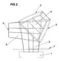
- FIG. 2shows a real imaging system that includes at least one aspheric curved reflector and a circular polarizer positioned in front of the image source to reduce ghosting.
- FIG. 3shows the view area of ghost imaging in a real imaging system that includes at least one aspheric curved reflector.
- FIG. 4shows a sample spectrograph of a typical neutral density window used in a real image system to reduce ghost imaging.
- FIG. 5shows a circular polarizer or neutral density window as used in an off-axis tilted optic real image system.
- FIG. 6shows how a circular polarizer reduces ghost imaging.
- an on-axis dual aspheric imaging systemfor example, as described in copending application Ser. No. 09/933,321, filed Aug. 2, 2001, entitled “IMAGE ENHANCEMENT IN A REAL IMAGE PROJECTION SYSTEM, USING ON-AXIS REFLECTORS, AT LEAST ONE OF WHICH IS ASPHERIC IN SHAPE”, the complete disclosure of which is hereby incorporated herein by reference, incorporates an image input source ( 1 ), two curved reflectors ( 3 , 4 , one of which has an aspheric revolution of curvature), a circular polarizing plate ( 7 ) and a real image projection ( 8 ).
- Light ( 2 ) from the image source or monitor ( 1 )strikes the upper curved reflector ( 3 ), and reflects in a collimated beam ( 5 ) striking the lower curved reflector ( 4 ), and then reflects in a converging beam ( 6 ), passing through the circular polarizer ( 7 ) and forming a real image ( 8 ) in free space in front of the display.
- the circular polarizer ( 7 )is made up of a quarter wave plate attached to a linear polarizing film.
- the linear polarizing filmis on the surface facing the real image and the opposite side from the curved reflectors.
- FIG. 2shows the same system as that of FIG. 1, with the circular polarizer ( 7 ) placed in front of the monitor face ( 1 ). This prevents a ghost image from being formed and reflected off the screen surface of the monitor ( 1 ).
- LCD monitorstypically require a contrast enhancement film to enhance the black levels. By substituting a circular polarizer ( 7 ) in front of the LCD monitor ( 1 ), the contrast levels are significantly improved and ghost imaging is significantly reduced.
- Ghost imaging of the real image optical system described in FIG. 1is described.
- An external light source ( 9 )enters the system through the view aperture window ( 7 ) and strikes the lower curved reflector ( 5 ). It is then reflected in a diverging beam, passing through the window ( 7 ) to form a ghost image ( 10 ) within the viewing area (C) shown.
- the ghost imagesare not visible within the normal viewing area (A), but in an environment where people are sitting or viewing from a lower angle, a real ghost image is formed and is visible.
- FIG. 4shows a typical spectrograph of the image color spectrum of light passing through a neutral density filter window.
- the neutral density windowreduces the ghost imaging, while enhancing the contrast of a real image.
- the neutral density windowoptionally is used in a tilted imaging system, for example, as described in copending application Ser. No. 10/126,167, filed Apr. 19, 2002, entitled “METHOD OF GHOST REDUCTION AND TRANSMISSION ENHANCEMENT FOR A REAL IMAGE PROJECTION SYSTEM”, the complete disclosure of which is hereby incorporated herein by reference.
- a neutral density filterabsorbs an equal percentage of light for all colors across the visible spectrum, thus maintaining the color integrity of the real image.
- FIG. 5shows a tilted real imaging system, such as that described in copending application Ser. No. 10/126,167, filed Apr. 19, 2002, entitled “METHOD OF GHOST REDUCTION AND TRANSMISSION ENHANCEMENT FOR A REAL IMAGE PROJECTION SYSTEM”.
- Light from the image source ( 1 )strikes a reflective flat mirror ( 13 ) and is reflected to a curved reflector ( 12 ) whose optical axis is tilted approximately 15 degrees off-axis to the viewing axis.
- the lightreflects off of the curved reflector ( 12 ) in a diverging beam, passing through the circular polarizer ( 7 ), forming a real image ( 8 ) in viewer space.
- the circular polarizer in the exampleis right circular, consisting of a linear polarizing film, and a quarter wave plate.
- the linear polarizing filmis facing the real image ( 8 ).
- Light from outside the system ( 9 )enters the system passing through the circular polarizer ( 7 ), first passing through the linear polarizer becoming vertically polarized, then passing through the quarter wave plate becoming right circular (e.g.), the right circular polarized light strikes the curved reflector ( 12 ), reversing the polarization to left circular.
- the reflected converging beam of lightthen strikes the circular polarizing window ( 7 ), passing first through the quarter wave where the left circular polarized light rotates to horizontally polarized light.
- the vertical linear polarizing film of the circular polarizer ( 7 )blocks the horizontally polarized light, and therefore no ghost image is visible in the system.
- An alternative embodimentuses a neutral density filter window, as described in FIG. 4, which significantly increases image contrast and significantly reduces ghost imaging.
- FIG. 6shows the polarization characteristics of a circular polarizer.
- unpolarized light ( 9 ) from outside the systempasses through the linear polarizing element ( 15 ) of the circular polarizing window, and becomes vertically polarized ( 16 ).
- the vertically polarized light ( 16 )then passes through the quarter wave plate element ( 14 ) of the circular polarizer, becoming right circularly polarized ( 17 ).
- the direction of circularityreverses when reflecting off of a mirror surface, so the right circularly polarized light ( 17 ) reflects off of the curved reflector ( 12 ), changing to left polarized light ( 18 ).
- the left circularly polarized light ( 18 )passes through the quarter wave element ( 14 ), it becomes horizontally polarized ( 19 ).
- the horizontally polarized light ( 19 )is blocked completely by the vertical linear polarizing element ( 15 ). Because there is no beamsplitter in the system, the circular polarization is not corrupted into elliptical polarization, so unlike traditional imaging systems of the prior art, the circular polarizing filter may be positioned at the system view aperture, rather than between a beamsplitter and curved mirror ( 12 ).
Landscapes
- Physics & Mathematics (AREA)
- General Physics & Mathematics (AREA)
- Optics & Photonics (AREA)
- Spectroscopy & Molecular Physics (AREA)
- Engineering & Computer Science (AREA)
- Multimedia (AREA)
- Signal Processing (AREA)
- Polarising Elements (AREA)
- Projection Apparatus (AREA)
Abstract
Description
This is a continuation-in-part patent application of application Ser. No. 09/933,331, filed Aug. 20, 2001. now U.S. Pat. No. 6,612,701, entitled “IMAGE ENHANCEMENT IN A REAL IMAGE PROJECTION SYSTEM, USING ON-AXIS REFLECTORS, AT LEAST ONE OF WHICH IS ASPHERIC IN SHAPE”, and application Ser. No. 09/557,859, filed Apr. 26, 2000, now abandoned entitled “REAL OR VIRTUAL IMAGING SYSTEM WITH REDUCED GHOST IMAGING”, which claims an invention which was disclosed in Provisional Application Number 60/131,320, filed April 27, 1999, entitled “NO GHOST FILTER”. The benefit under 35 USC §119(e) of the United States provisional application is hereby claimed, and the three aforementioned applications are hereby incorporated herein by reference in their entirety.
1. Field of the Invention
The invention pertains to the field of real image display systems. More particularly, the invention pertains to a real image display system incorporating two curved mirrors, at least one of which has an aspheric surface of revolution, or a tilted spherical mirror whose optical path does not reflect off of a beamsplitter surface.
2. Description of Related Art
It is desirable in modem imaging display systems to provide images having good contrast that appear sharp and undistorted to the viewer. One of the major problems in presenting a clear image is that real and infinity imaging systems generally employ curved mirrors and exhibit problems with secondary ghosting, that is, forming an additional image of the projected light source image at the point of observation. This occurs when outside light enters an imaging system and is projected as an additional ghost image near the focal point at which the primary image is projected and viewed.
The preferred solution to this problem is the use of a circular polarizer. The problem with this, however, is that conventional real image projection devices incorporate a beamsplitter tilted at 45 degrees to divert the converging imaging beam to form a real image outside of the device in viewer space. The circular polarizer will not block the ghosts when positioned at the window aperture of the system, because circularly polarized light will be distorted to elliptically polarized light when transmitting through a tilted beamsplitter, and will not transform back to circular when passing back through the beamsplitter after reflecting off of the curved reflector. The elliptically polarized light, therefore will not revert to linear after passing through the quarter wave plate on the second pass, and therefore will not be blocked. The compromise has been to position the quarter wave element of the circular polarizer between the curved mirror and the beamsplitter to avoid elliptical distortion, so the light is circularly polarized after passing through the beamsplitter. The difficulty with this approach is that the size of the quarter wave plate must be nearly equal in size to the curved mirror, and large quarter wave plates are not readily accessible or affordable. The size of the material required becomes smaller as its position nears the real image projection focal point, because the beampath is converging to form the real image. This elliptical distortion is the reason that prior art systems specify that the quarter wave element of the circular polarizer must be located between the beamsplitter and the curved mirror.
Briefly stated, a real image display system includes a primary image source for projecting a primary image from the start of a primary light path to an end of the primary light path at which the primary image is viewable, two reflectors positioned in the primary light path between the primary image source and the projected real image, a circular polarizer for circularly polarizing a light beam positioned in the primary light path between the mirror and real image, whereby outside light entering the system is substantially blocked before exiting the system, thereby substantially eliminating ghost image formation caused by outside light sources.
The circular polarizing plate is extremely effective, particularly in systems that do not include a beamsplitter positioned at a 45 degree angle to the optical axis, as in prior art systems, such as those described in U.S. Pat. Nos. 5,585,946 and 5,305,124. The systems disclosed in these patents place the circular polarizer elements between the mirror and beamsplitter, because of the effect of elliptical polarization caused by circularly polarized light passing through a beamsplitter at an angle other than normal to the surface. The circular polarizer placed at the window aperture of a conventional real image projection device containing a 45 degree positioned beamsplitter will not effectively block the ghost imaging.
FIG. 1 shows a real imaging system that includes at least one aspheric curved reflector and a circular polarizer or neutral density window for ghost reduction.
FIG. 2 shows a real imaging system that includes at least one aspheric curved reflector and a circular polarizer positioned in front of the image source to reduce ghosting.
FIG. 3 shows the view area of ghost imaging in a real imaging system that includes at least one aspheric curved reflector.
FIG. 4 shows a sample spectrograph of a typical neutral density window used in a real image system to reduce ghost imaging.
FIG. 5 shows a circular polarizer or neutral density window as used in an off-axis tilted optic real image system.
FIG. 6 shows how a circular polarizer reduces ghost imaging.
Referring to FIG. 1, an on-axis dual aspheric imaging system, for example, as described in copending application Ser. No. 09/933,321, filed Aug. 2, 2001, entitled “IMAGE ENHANCEMENT IN A REAL IMAGE PROJECTION SYSTEM, USING ON-AXIS REFLECTORS, AT LEAST ONE OF WHICH IS ASPHERIC IN SHAPE”, the complete disclosure of which is hereby incorporated herein by reference, incorporates an image input source (1), two curved reflectors (3,4, one of which has an aspheric revolution of curvature), a circular polarizing plate (7) and a real image projection (8). Light (2) from the image source or monitor (1) strikes the upper curved reflector (3), and reflects in a collimated beam (5) striking the lower curved reflector (4), and then reflects in a converging beam (6), passing through the circular polarizer (7) and forming a real image (8) in free space in front of the display. The circular polarizer (7) is made up of a quarter wave plate attached to a linear polarizing film. The linear polarizing film is on the surface facing the real image and the opposite side from the curved reflectors.
FIG. 2 shows the same system as that of FIG. 1, with the circular polarizer (7) placed in front of the monitor face (1). This prevents a ghost image from being formed and reflected off the screen surface of the monitor (1). LCD monitors typically require a contrast enhancement film to enhance the black levels. By substituting a circular polarizer (7) in front of the LCD monitor (1), the contrast levels are significantly improved and ghost imaging is significantly reduced.
Referring to FIG. 3, ghost imaging of the real image optical system described in FIG. 1 is described. An external light source (9) enters the system through the view aperture window (7) and strikes the lower curved reflector (5). It is then reflected in a diverging beam, passing through the window (7) to form a ghost image (10) within the viewing area (C) shown. In a dual aspheric real image system, the ghost images are not visible within the normal viewing area (A), but in an environment where people are sitting or viewing from a lower angle, a real ghost image is formed and is visible.
FIG. 4 shows a typical spectrograph of the image color spectrum of light passing through a neutral density filter window. The neutral density window reduces the ghost imaging, while enhancing the contrast of a real image. The neutral density window optionally is used in a tilted imaging system, for example, as described in copending application Ser. No. 10/126,167, filed Apr. 19, 2002, entitled “METHOD OF GHOST REDUCTION AND TRANSMISSION ENHANCEMENT FOR A REAL IMAGE PROJECTION SYSTEM”, the complete disclosure of which is hereby incorporated herein by reference. A neutral density filter absorbs an equal percentage of light for all colors across the visible spectrum, thus maintaining the color integrity of the real image.
FIG. 5 shows a tilted real imaging system, such as that described in copending application Ser. No. 10/126,167, filed Apr. 19, 2002, entitled “METHOD OF GHOST REDUCTION AND TRANSMISSION ENHANCEMENT FOR A REAL IMAGE PROJECTION SYSTEM”. Light from the image source (1) strikes a reflective flat mirror (13) and is reflected to a curved reflector (12) whose optical axis is tilted approximately 15 degrees off-axis to the viewing axis. The light reflects off of the curved reflector (12) in a diverging beam, passing through the circular polarizer (7), forming a real image (8) in viewer space. The circular polarizer in the example is right circular, consisting of a linear polarizing film, and a quarter wave plate. The linear polarizing film is facing the real image (8). Light from outside the system (9) enters the system passing through the circular polarizer (7), first passing through the linear polarizer becoming vertically polarized, then passing through the quarter wave plate becoming right circular (e.g.), the right circular polarized light strikes the curved reflector (12), reversing the polarization to left circular. The reflected converging beam of light then strikes the circular polarizing window (7), passing first through the quarter wave where the left circular polarized light rotates to horizontally polarized light. The vertical linear polarizing film of the circular polarizer (7) blocks the horizontally polarized light, and therefore no ghost image is visible in the system.
An alternative embodiment uses a neutral density filter window, as described in FIG. 4, which significantly increases image contrast and significantly reduces ghost imaging.
FIG. 6 shows the polarization characteristics of a circular polarizer. In the example, unpolarized light (9) from outside the system passes through the linear polarizing element (15) of the circular polarizing window, and becomes vertically polarized (16). The vertically polarized light (16) then passes through the quarter wave plate element (14) of the circular polarizer, becoming right circularly polarized (17). The direction of circularity reverses when reflecting off of a mirror surface, so the right circularly polarized light (17) reflects off of the curved reflector (12), changing to left polarized light (18). As the left circularly polarized light (18) passes through the quarter wave element (14), it becomes horizontally polarized (19). The horizontally polarized light (19) is blocked completely by the vertical linear polarizing element (15). Because there is no beamsplitter in the system, the circular polarization is not corrupted into elliptical polarization, so unlike traditional imaging systems of the prior art, the circular polarizing filter may be positioned at the system view aperture, rather than between a beamsplitter and curved mirror (12).
Accordingly, it is to be understood that the embodiments of the invention herein described are merely illustrative of the application of the principles of the invention. Reference herein to details of the illustrated embodiments is not intended to limit the scope of the claims, which themselves recite those features regarded as essential to the invention.
Claims (20)
1. A real image display system comprising:
a) a real imaging system for projecting a real image, said imaging system incorporating curved reflectors, at least one of which comprises an aspheric surface of revolution; and
b) a circular polarizing window or a neutral density filter window; and
c) wherein said real image display system projects a real image that appears to a viewer thereof as an image floating in space.
2. The real image display system ofclaim 1 , wherein said neutral density filter window is between 15% and 40% absorption.
3. The real image display system ofclaim 2 , wherein said neutral density filter has an anti-reflective coating on one or both surfaces thereof.
4. The real image display system ofclaim 1 , wherein said circular polarizing window comprises a linear polarizing film and quarter wave plate, said linear polarizing film facing said real image, and said quarter wave plate facing at least one of said curved reflectors.
5. The real image display system ofclaim 4 , wherein said circular polarizing window is secured to a clear substrate or between two clear substrates.
6. The real image display system ofclaim 4 , wherein said circular polarizing window includes an anti-reflective coating on one or both surfaces thereof.
7. The real image display system ofclaim 4 , wherein said real imaging system does not utilize a tilted beamsplitter between said curved reflector and said real image, such that said real image is not reflected from a beamsplitter surface.
8. A real image projection system, comprising:
a) a visual staging station defining a space for viewing images from a vantage point along a viewing axis;
b) at least two curved optics of the conical family of curves, at least one of said optics comprising an aspherical surface of revolution, wherein said curved optics are arranged such that an object positioned substantially at or near a focal point of one of said curved optics forms a real image positioned substantially at or near a focal point of another of said curved optics, and said real image is projected along said viewing axis and appears as a floating image when viewed from said visual staging station; and
c) a circular polarizing window or a neutral density filter window.
9. The real image display system ofclaim 8 , wherein said neutral density filter window is between 15% and 40% absorption.
10. The real image display system ofclaim 9 , wherein said neutral density filter has an anti-reflective coating on one or both surfaces thereof.
11. The real image display system ofclaim 8 , wherein said circular polarizing window comprises a linear polarizing film and quarter wave plate, said linear polarizing film facing said real image, and said quarter wave plate facing at least one of said curved reflectors.
12. The real image display system ofclaim 11 , wherein said circular polarizing window is secured to a clear substrate or between two clear substrates.
13. The real image display system ofclaim 9 , wherein said circular polarizing window includes an anti-reflective coating on one or both surfaces thereof.
14. The real image display system ofclaim 9 , wherein said real imaging system does not utilize a tilted beamsplitter between said curved reflector and said real image, such that said real image is not reflected from a beamsplitter surface.
15. A real image projection system, comprising:
a) a plurality of curved reflectors for projecting a real image, at least one of said reflector comprising an aspherical surface of revolution and being positioned in a tilted configuration, wherein an optical axis of said reflector is not coincident with a viewing axis, and a beampath between a target source and said curved reflector neither passes through nor reflects off of a beamsplitter; and
b) a circular polarizing window or a neutral density filter window; and
c) wherein said real image projection system projects a real image that appears to a viewer thereof as an image floating in space.
16. The real image display system ofclaim 15 , wherein said neutral density filter window is between 15% and 40% absorption.
17. The real image display system ofclaim 16 , wherein said neutral density filter has an anti-reflective coating on one or both surfaces thereof.
18. The real image display system ofclaim 15 , wherein said circular polarizing window comprises a linear polarizing film and quarter wave plate, said linear polarizing film facing said real image, and said quarter wave plate facing at least one of said curved reflectors.
19. The real image display system ofclaim 18 , wherein said circular polarizing window is secured to a clear substrate or between two clear substrates.
20. The real image display system ofclaim 19 , wherein said circular polarizing window includes an anti-reflective coating on one or both surfaces thereof.
Priority Applications (2)
| Application Number | Priority Date | Filing Date | Title |
|---|---|---|---|
| US10/350,762US6798579B2 (en) | 1999-04-27 | 2003-01-24 | Real imaging system with reduced ghost imaging |
| US10/388,062US6935747B2 (en) | 1999-04-27 | 2003-03-13 | Image enhancement and aberration corrections in a small real image projection system |
Applications Claiming Priority (4)
| Application Number | Priority Date | Filing Date | Title |
|---|---|---|---|
| US13132099P | 1999-04-27 | 1999-04-27 | |
| US55785900A | 2000-04-26 | 2000-04-26 | |
| US09/933,331US6612701B2 (en) | 2001-08-20 | 2001-08-20 | Image enhancement in a real image projection system, using on-axis reflectors, at least one of which is aspheric in shape |
| US10/350,762US6798579B2 (en) | 1999-04-27 | 2003-01-24 | Real imaging system with reduced ghost imaging |
Related Parent Applications (4)
| Application Number | Title | Priority Date | Filing Date |
|---|---|---|---|
| US55785900AContinuation-In-Part | 1999-04-27 | 2000-04-26 | |
| US09/933,331Continuation-In-PartUS6612701B2 (en) | 1999-04-27 | 2001-08-20 | Image enhancement in a real image projection system, using on-axis reflectors, at least one of which is aspheric in shape |
| US09/933,321Continuation-In-PartUS8032076B2 (en) | 2001-08-20 | 2001-08-20 | Cellular telephone and multimedia accessory audio system adaptor and methods therefor |
| US09/946,183Continuation-In-PartUS6598976B2 (en) | 1999-04-27 | 2001-09-05 | Method and apparatus for image enhancement and aberration corrections in a small real image projection system, using an off-axis reflector, neutral density window, and an aspheric corrected surface of revolution |
Related Child Applications (1)
| Application Number | Title | Priority Date | Filing Date |
|---|---|---|---|
| US10/388,062Continuation-In-PartUS6935747B2 (en) | 1999-04-27 | 2003-03-13 | Image enhancement and aberration corrections in a small real image projection system |
Publications (2)
| Publication Number | Publication Date |
|---|---|
| US20030147145A1 US20030147145A1 (en) | 2003-08-07 |
| US6798579B2true US6798579B2 (en) | 2004-09-28 |
Family
ID=29740661
Family Applications (1)
| Application Number | Title | Priority Date | Filing Date |
|---|---|---|---|
| US10/350,762Expired - Fee RelatedUS6798579B2 (en) | 1999-04-27 | 2003-01-24 | Real imaging system with reduced ghost imaging |
Country Status (1)
| Country | Link |
|---|---|
| US (1) | US6798579B2 (en) |
Cited By (40)
| Publication number | Priority date | Publication date | Assignee | Title |
|---|---|---|---|---|
| US20050094103A1 (en)* | 2001-08-20 | 2005-05-05 | Optical Products Development Corporation | Real image projection system for gaming, ATM, vending machines, merchandising displays and related applications |
| US20080151379A1 (en)* | 2005-02-10 | 2008-06-26 | Lumus Ltd. | Substrate-Guide Optical Device Utilizing Polarization Beam Splitters |
| US20180164598A1 (en)* | 2016-12-08 | 2018-06-14 | Futurus Technology Co., Ltd. | System for imaging in the air |
| US10073264B2 (en) | 2007-08-03 | 2018-09-11 | Lumus Ltd. | Substrate-guide optical device |
| US10261321B2 (en) | 2005-11-08 | 2019-04-16 | Lumus Ltd. | Polarizing optical system |
| US10302835B2 (en) | 2017-02-22 | 2019-05-28 | Lumus Ltd. | Light guide optical assembly |
| US10437031B2 (en) | 2016-11-08 | 2019-10-08 | Lumus Ltd. | Light-guide device with optical cutoff edge and corresponding production methods |
| US10481319B2 (en) | 2017-03-22 | 2019-11-19 | Lumus Ltd. | Overlapping facets |
| US10506220B2 (en) | 2018-01-02 | 2019-12-10 | Lumus Ltd. | Augmented reality displays with active alignment and corresponding methods |
| US10520731B2 (en) | 2014-11-11 | 2019-12-31 | Lumus Ltd. | Compact head-mounted display system protected by a hyperfine structure |
| US10520732B2 (en) | 2012-05-21 | 2019-12-31 | Lumus Ltd. | Head-mounted display eyeball tracker integrated system |
| US10551544B2 (en) | 2018-01-21 | 2020-02-04 | Lumus Ltd. | Light-guide optical element with multiple-axis internal aperture expansion |
| US10564417B2 (en) | 2016-10-09 | 2020-02-18 | Lumus Ltd. | Aperture multiplier using a rectangular waveguide |
| US10809528B2 (en) | 2014-04-23 | 2020-10-20 | Lumus Ltd. | Compact head-mounted display system |
| US10895679B2 (en) | 2017-04-06 | 2021-01-19 | Lumus Ltd. | Light-guide optical element and method of its manufacture |
| US11262587B2 (en) | 2018-05-22 | 2022-03-01 | Lumus Ltd. | Optical system and method for improvement of light field uniformity |
| US11448816B2 (en) | 2019-01-24 | 2022-09-20 | Lumus Ltd. | Optical systems including light-guide optical elements with two-dimensional expansion |
| US11500143B2 (en) | 2017-01-28 | 2022-11-15 | Lumus Ltd. | Augmented reality imaging system |
| US11523092B2 (en) | 2019-12-08 | 2022-12-06 | Lumus Ltd. | Optical systems with compact image projector |
| US11526003B2 (en) | 2018-05-23 | 2022-12-13 | Lumus Ltd. | Optical system including light-guide optical element with partially-reflective internal surfaces |
| US11543583B2 (en) | 2018-09-09 | 2023-01-03 | Lumus Ltd. | Optical systems including light-guide optical elements with two-dimensional expansion |
| US11561335B2 (en) | 2019-12-05 | 2023-01-24 | Lumus Ltd. | Light-guide optical element employing complementary coated partial reflectors, and light-guide optical element having reduced light scattering |
| US11630260B2 (en) | 2020-05-24 | 2023-04-18 | Lumus Ltd. | Production method and corresponding structures of compound light-guide optical elements |
| US11719947B1 (en) | 2019-06-30 | 2023-08-08 | Apple Inc. | Prism beam expander |
| US11789264B2 (en) | 2021-07-04 | 2023-10-17 | Lumus Ltd. | Display with stacked light-guide elements providing different parts of field of view |
| US11796729B2 (en) | 2021-02-25 | 2023-10-24 | Lumus Ltd. | Optical aperture multipliers having a rectangular waveguide |
| US11815677B1 (en) | 2019-05-15 | 2023-11-14 | Apple Inc. | Display using scanning-based sequential pupil expansion |
| US11822088B2 (en) | 2021-05-19 | 2023-11-21 | Lumus Ltd. | Active optical engine |
| US11860369B2 (en) | 2021-03-01 | 2024-01-02 | Lumus Ltd. | Optical system with compact coupling from a projector into a waveguide |
| US11886008B2 (en) | 2021-08-23 | 2024-01-30 | Lumus Ltd. | Methods of fabrication of compound light-guide optical elements having embedded coupling-in reflectors |
| US11885966B2 (en) | 2019-12-30 | 2024-01-30 | Lumus Ltd. | Optical systems including light-guide optical elements with two-dimensional expansion |
| US11914161B2 (en) | 2019-06-27 | 2024-02-27 | Lumus Ltd. | Apparatus and methods for eye tracking based on eye imaging via light-guide optical element |
| US11914187B2 (en) | 2019-07-04 | 2024-02-27 | Lumus Ltd. | Image waveguide with symmetric beam multiplication |
| US12124037B2 (en) | 2020-05-24 | 2024-10-22 | Lumus Ltd. | Compound light-guide optical elements |
| US12124050B2 (en) | 2019-02-28 | 2024-10-22 | Lumus Ltd. | Compact collimated image projector |
| US12135445B2 (en) | 2019-04-15 | 2024-11-05 | Lumus Ltd. | Method of fabricating a light-guide optical element |
| US12140790B2 (en) | 2019-07-18 | 2024-11-12 | Lumus Ltd. | Encapsulated light-guide optical element |
| US12222508B2 (en) | 2020-08-26 | 2025-02-11 | Lumus Ltd. | Generation of color images using white light as source |
| US12320983B1 (en) | 2022-08-18 | 2025-06-03 | Lumus Ltd. | Image projector with polarizing catadioptric collimator |
| US12372799B2 (en) | 2020-05-12 | 2025-07-29 | Lumus Ltd. | Rotatable lightpipe |
Families Citing this family (8)
| Publication number | Priority date | Publication date | Assignee | Title |
|---|---|---|---|---|
| US6935747B2 (en)* | 1999-04-27 | 2005-08-30 | Optical Products Development | Image enhancement and aberration corrections in a small real image projection system |
| US6964487B2 (en) | 2004-02-10 | 2005-11-15 | Starvision Optics, Inc. | Image display device |
| DE102009057033A1 (en)* | 2009-12-04 | 2011-06-09 | Bayerische Motoren Werke Aktiengesellschaft | Projection unit for a head-up display and method for operating a projection unit for a head-up display |
| US9444978B2 (en) | 2013-06-17 | 2016-09-13 | The University Of Maryland, Baltimore County | Turbulence-free camera system and related method of image enhancement |
| DE102015222842A1 (en)* | 2015-11-19 | 2017-05-24 | Robert Bosch Gmbh | Cover element for covering a projection opening of a head-up display, head-up display and method for passing light through a cover |
| DE102016202464A1 (en)* | 2016-02-18 | 2017-08-24 | Bayerische Motoren Werke Aktiengesellschaft | Projection device for a head-up display, head-up display and vehicle |
| CN107462932B (en)* | 2017-08-04 | 2020-03-17 | 西安交通大学 | Visual calculation ghost imaging system and imaging method based on optical calculation |
| IT201700122280A1 (en)* | 2017-10-27 | 2019-04-27 | 3D I V E S R L | Light field volumetric device for displaying fluctuating and stereoscopic 3D image streams 5 and relative method |
Citations (56)
| Publication number | Priority date | Publication date | Assignee | Title |
|---|---|---|---|---|
| US3647284A (en) | 1970-11-30 | 1972-03-07 | Virgil B Elings | Optical display device |
| USRE27356E (en) | 1970-08-17 | 1972-05-09 | Infinite optical image-forming apparatus | |
| US3682532A (en) | 1971-02-03 | 1972-08-08 | Singer Co | Optical system to reduce image to lens distance by polarization control |
| US4093347A (en) | 1976-05-10 | 1978-06-06 | Farrand Optical Co., Inc. | Optical simulation apparatus using controllable real-life element |
| US4112462A (en) | 1976-11-26 | 1978-09-05 | The Singer Company | Infinity image display having increased vertical field of view |
| US4653875A (en) | 1984-11-02 | 1987-03-31 | Hines Stephen P | Infinity display apparatus using cylindrical beam-splitters |
| US4721380A (en) | 1985-02-22 | 1988-01-26 | Constantin Systems, Inc. | Portable opaque projector |
| US4802750A (en) | 1987-08-03 | 1989-02-07 | Grand Mirage | Real image projection system with two curved reflectors of paraboloid of revolution shape having each vertex coincident with the focal point of the other |
| US4810092A (en) | 1986-02-21 | 1989-03-07 | Midac Corporation | Economical spectrometer unit having simplified structure |
| US4850152A (en) | 1986-12-22 | 1989-07-25 | Carl-Zeiss-Stiftung | Apparatus for lapping and polishing optical surfaces |
| US4989953A (en)* | 1989-01-24 | 1991-02-05 | Kirschner Kevin A | Video display terminal filter |
| US5237157A (en) | 1990-09-13 | 1993-08-17 | Intouch Group, Inc. | Kiosk apparatus and method for point of preview and for compilation of market data |
| US5257130A (en) | 1992-01-30 | 1993-10-26 | The Walt Disney Company | Apparatus and method for creating a real image illusion |
| US5268775A (en) | 1991-02-19 | 1993-12-07 | Hughes-Jvc Technology Corporation | Contrast enhancement and ghost elimination, for reflective light valve system |
| US5291897A (en) | 1990-09-06 | 1994-03-08 | Instrumentarium Corporation | Fastening member |
| US5305124A (en) | 1992-04-07 | 1994-04-19 | Hughes Aircraft Company | Virtual image display system |
| US5311357A (en) | 1992-01-28 | 1994-05-10 | Image Technology Associates | Device for the creation of three-dimensional images |
| US5369450A (en) | 1993-06-01 | 1994-11-29 | The Walt Disney Company | Electronic and computational correction of chromatic aberration associated with an optical system used to view a color video display |
| US5380999A (en) | 1993-12-29 | 1995-01-10 | International Business Machines, Corp. | Linear scanning using a single illumination and imaging optic stations with a first pair of parallel mirrors and a second pair of mirrors extending into paths of light beams |
| JPH0743634A (en) | 1993-05-14 | 1995-02-14 | Olympus Optical Co Ltd | Face or head mounted display device |
| US5486840A (en) | 1994-03-21 | 1996-01-23 | Delco Electronics Corporation | Head up display with incident light filter |
| JPH08152579A (en) | 1994-11-28 | 1996-06-11 | Olympus Optical Co Ltd | Visual display device |
| US5539578A (en) | 1993-03-02 | 1996-07-23 | Olympus Optical Co., Ltd. | Image display apparatus |
| US5576887A (en) | 1995-06-22 | 1996-11-19 | Honeywell Inc. | Head gear display system using off-axis image sources |
| US5585946A (en) | 1994-08-19 | 1996-12-17 | Vivitek Co., Ltd. | Virtual image display system with reduced ambient reflection and low radiation |
| US5596451A (en) | 1995-01-30 | 1997-01-21 | Displaytech, Inc. | Miniature image generator including optics arrangement |
| US5606458A (en) | 1994-08-24 | 1997-02-25 | Fergason; James L. | Head mounted display and viewing system using a remote retro-reflector and method of displaying and viewing an image |
| US5621572A (en) | 1994-08-24 | 1997-04-15 | Fergason; James L. | Optical system for a head mounted display using a retro-reflector and method of displaying an image |
| US5687025A (en) | 1995-05-25 | 1997-11-11 | Canon Kabushiki Kaisha | Image display apparatus and image pickup apparatus |
| US5777794A (en)* | 1995-09-26 | 1998-07-07 | Olympus Optical Co., Ltd. | Image display apparatus |
| US5777795A (en) | 1994-10-17 | 1998-07-07 | University Of North Carolina | Optical path extender for compact imaging display systems |
| US5782547A (en) | 1996-11-08 | 1998-07-21 | Videotronic Systems | Magnified background image spatial object display |
| US5831712A (en) | 1994-11-02 | 1998-11-03 | Olympus Optical Co., Ltd. | Optical apparatus having ocular optical system |
| US5886818A (en) | 1992-12-03 | 1999-03-23 | Dimensional Media Associates | Multi-image compositing |
| US5903396A (en) | 1997-10-17 | 1999-05-11 | I/O Display Systems, Llc | Intensified visual display |
| US5961192A (en) | 1998-02-06 | 1999-10-05 | The Little Tikes Company | Mobile computer work station |
| WO2000065844A1 (en) | 1999-04-27 | 2000-11-02 | Optical Products Development Corporation | Real or virtual imaging system with reduced ghost imaging |
| US6163408A (en) | 1998-10-13 | 2000-12-19 | Larussa; Joseph | Compact visual simulation system |
| US6262849B1 (en) | 1997-10-10 | 2001-07-17 | Sextant Avionique | Optical device for helmet visor comprising a Mangin mirror |
| US6262841B1 (en)* | 1997-11-24 | 2001-07-17 | Bruce D. Dike | Apparatus for projecting a real image in space |
| US6315416B1 (en) | 1998-10-16 | 2001-11-13 | Juan Dominguez-Montes | Optical system capable of creating the three-dimensional image of an object in space without inversion |
| US6318868B1 (en) | 1997-05-01 | 2001-11-20 | Larussa Joseph A. | Interactive virtual image store window |
| US20020027718A1 (en) | 2000-04-25 | 2002-03-07 | Silicon Valley Group, Inc. | Optical reduction system with elimination of reticle diffraction induced bias |
| US6364490B1 (en) | 1996-11-15 | 2002-04-02 | Vantage Lighting Incorporated | Virtual image projection device |
| US20020044287A1 (en)* | 2000-02-17 | 2002-04-18 | Nikon Corporation | Point diffraction interferometer, manufacturing method for reflecting mirror, and projection exposure apparatus |
| US6390626B2 (en) | 1996-10-17 | 2002-05-21 | Duke University | Image projection system engine assembly |
| US6421182B1 (en) | 1998-04-09 | 2002-07-16 | Central Research Laboratories, Limited | Apparatus for displaying an image suspended in space |
| US6445407B1 (en) | 1998-12-07 | 2002-09-03 | Donald Edward Wright | 3-dimensional visual system |
| US20020184104A1 (en) | 2001-05-31 | 2002-12-05 | James Littman | Integrated retail and wholesale system |
| US6497484B1 (en) | 1998-04-15 | 2002-12-24 | Holo-Gone, Llc | Optical imaging apparatus |
| US20030035086A1 (en) | 2001-08-20 | 2003-02-20 | Robinson Douglas L. | Real image projection device incorporating e-mail register |
| US6598976B2 (en) | 2001-09-05 | 2003-07-29 | Optical Products Development Corp. | Method and apparatus for image enhancement and aberration corrections in a small real image projection system, using an off-axis reflector, neutral density window, and an aspheric corrected surface of revolution |
| US6607275B1 (en) | 2002-03-20 | 2003-08-19 | The Neiman Marcus Group, Inc. | Merchandise display case and system |
| US6612701B2 (en) | 2001-08-20 | 2003-09-02 | Optical Products Development Corporation | Image enhancement in a real image projection system, using on-axis reflectors, at least one of which is aspheric in shape |
| US20030197839A1 (en) | 2002-04-19 | 2003-10-23 | Robinson Douglas L. | Method of ghost reduction and transmission enhancement for a real image projection system |
| US6650470B1 (en) | 2002-05-16 | 2003-11-18 | Optical Products Development Corp. | Semi-transparent graphic window for a real imaging system |
Family Cites Families (2)
| Publication number | Priority date | Publication date | Assignee | Title |
|---|---|---|---|---|
| US2003A (en)* | 1841-03-12 | Improvement in horizontal windivhlls | ||
| US6318686B1 (en)* | 2000-04-21 | 2001-11-20 | Keum-Hwan No | Bracket for electric pole |
- 2003
- 2003-01-24USUS10/350,762patent/US6798579B2/ennot_activeExpired - Fee Related
Patent Citations (59)
| Publication number | Priority date | Publication date | Assignee | Title |
|---|---|---|---|---|
| USRE27356E (en) | 1970-08-17 | 1972-05-09 | Infinite optical image-forming apparatus | |
| US3647284A (en) | 1970-11-30 | 1972-03-07 | Virgil B Elings | Optical display device |
| US3682532A (en) | 1971-02-03 | 1972-08-08 | Singer Co | Optical system to reduce image to lens distance by polarization control |
| US4093347A (en) | 1976-05-10 | 1978-06-06 | Farrand Optical Co., Inc. | Optical simulation apparatus using controllable real-life element |
| US4112462A (en) | 1976-11-26 | 1978-09-05 | The Singer Company | Infinity image display having increased vertical field of view |
| US4653875A (en) | 1984-11-02 | 1987-03-31 | Hines Stephen P | Infinity display apparatus using cylindrical beam-splitters |
| US4721380A (en) | 1985-02-22 | 1988-01-26 | Constantin Systems, Inc. | Portable opaque projector |
| US4810092A (en) | 1986-02-21 | 1989-03-07 | Midac Corporation | Economical spectrometer unit having simplified structure |
| US4850152A (en) | 1986-12-22 | 1989-07-25 | Carl-Zeiss-Stiftung | Apparatus for lapping and polishing optical surfaces |
| US4802750A (en) | 1987-08-03 | 1989-02-07 | Grand Mirage | Real image projection system with two curved reflectors of paraboloid of revolution shape having each vertex coincident with the focal point of the other |
| US4989953A (en)* | 1989-01-24 | 1991-02-05 | Kirschner Kevin A | Video display terminal filter |
| US5291897A (en) | 1990-09-06 | 1994-03-08 | Instrumentarium Corporation | Fastening member |
| US5237157A (en) | 1990-09-13 | 1993-08-17 | Intouch Group, Inc. | Kiosk apparatus and method for point of preview and for compilation of market data |
| US5268775A (en) | 1991-02-19 | 1993-12-07 | Hughes-Jvc Technology Corporation | Contrast enhancement and ghost elimination, for reflective light valve system |
| US5311357A (en) | 1992-01-28 | 1994-05-10 | Image Technology Associates | Device for the creation of three-dimensional images |
| US5257130A (en) | 1992-01-30 | 1993-10-26 | The Walt Disney Company | Apparatus and method for creating a real image illusion |
| US5305124A (en) | 1992-04-07 | 1994-04-19 | Hughes Aircraft Company | Virtual image display system |
| US5886818A (en) | 1992-12-03 | 1999-03-23 | Dimensional Media Associates | Multi-image compositing |
| USRE37667E1 (en) | 1993-03-02 | 2002-04-23 | Olympus Optical Co. | Head-mounted image display apparatus |
| US5539578A (en) | 1993-03-02 | 1996-07-23 | Olympus Optical Co., Ltd. | Image display apparatus |
| US5708529A (en) | 1993-03-02 | 1998-01-13 | Olympus Optical Co., Ltd. | Head-mounted image display apparatus |
| JPH0743634A (en) | 1993-05-14 | 1995-02-14 | Olympus Optical Co Ltd | Face or head mounted display device |
| US5369450A (en) | 1993-06-01 | 1994-11-29 | The Walt Disney Company | Electronic and computational correction of chromatic aberration associated with an optical system used to view a color video display |
| US5380999A (en) | 1993-12-29 | 1995-01-10 | International Business Machines, Corp. | Linear scanning using a single illumination and imaging optic stations with a first pair of parallel mirrors and a second pair of mirrors extending into paths of light beams |
| US5486840A (en) | 1994-03-21 | 1996-01-23 | Delco Electronics Corporation | Head up display with incident light filter |
| US5585946A (en) | 1994-08-19 | 1996-12-17 | Vivitek Co., Ltd. | Virtual image display system with reduced ambient reflection and low radiation |
| US5621572A (en) | 1994-08-24 | 1997-04-15 | Fergason; James L. | Optical system for a head mounted display using a retro-reflector and method of displaying an image |
| US5606458A (en) | 1994-08-24 | 1997-02-25 | Fergason; James L. | Head mounted display and viewing system using a remote retro-reflector and method of displaying and viewing an image |
| US5777795A (en) | 1994-10-17 | 1998-07-07 | University Of North Carolina | Optical path extender for compact imaging display systems |
| US5831712A (en) | 1994-11-02 | 1998-11-03 | Olympus Optical Co., Ltd. | Optical apparatus having ocular optical system |
| JPH08152579A (en) | 1994-11-28 | 1996-06-11 | Olympus Optical Co Ltd | Visual display device |
| US5596451A (en) | 1995-01-30 | 1997-01-21 | Displaytech, Inc. | Miniature image generator including optics arrangement |
| US5687025A (en) | 1995-05-25 | 1997-11-11 | Canon Kabushiki Kaisha | Image display apparatus and image pickup apparatus |
| US5576887A (en) | 1995-06-22 | 1996-11-19 | Honeywell Inc. | Head gear display system using off-axis image sources |
| US5777794A (en)* | 1995-09-26 | 1998-07-07 | Olympus Optical Co., Ltd. | Image display apparatus |
| US6390626B2 (en) | 1996-10-17 | 2002-05-21 | Duke University | Image projection system engine assembly |
| US5782547A (en) | 1996-11-08 | 1998-07-21 | Videotronic Systems | Magnified background image spatial object display |
| US6364490B1 (en) | 1996-11-15 | 2002-04-02 | Vantage Lighting Incorporated | Virtual image projection device |
| US6318868B1 (en) | 1997-05-01 | 2001-11-20 | Larussa Joseph A. | Interactive virtual image store window |
| US6262849B1 (en) | 1997-10-10 | 2001-07-17 | Sextant Avionique | Optical device for helmet visor comprising a Mangin mirror |
| US5903396A (en) | 1997-10-17 | 1999-05-11 | I/O Display Systems, Llc | Intensified visual display |
| US6262841B1 (en)* | 1997-11-24 | 2001-07-17 | Bruce D. Dike | Apparatus for projecting a real image in space |
| US5961192A (en) | 1998-02-06 | 1999-10-05 | The Little Tikes Company | Mobile computer work station |
| US6421182B1 (en) | 1998-04-09 | 2002-07-16 | Central Research Laboratories, Limited | Apparatus for displaying an image suspended in space |
| US6497484B1 (en) | 1998-04-15 | 2002-12-24 | Holo-Gone, Llc | Optical imaging apparatus |
| US6163408A (en) | 1998-10-13 | 2000-12-19 | Larussa; Joseph | Compact visual simulation system |
| US6315416B1 (en) | 1998-10-16 | 2001-11-13 | Juan Dominguez-Montes | Optical system capable of creating the three-dimensional image of an object in space without inversion |
| US6445407B1 (en) | 1998-12-07 | 2002-09-03 | Donald Edward Wright | 3-dimensional visual system |
| WO2000065844A1 (en) | 1999-04-27 | 2000-11-02 | Optical Products Development Corporation | Real or virtual imaging system with reduced ghost imaging |
| US20020044287A1 (en)* | 2000-02-17 | 2002-04-18 | Nikon Corporation | Point diffraction interferometer, manufacturing method for reflecting mirror, and projection exposure apparatus |
| US20020027718A1 (en) | 2000-04-25 | 2002-03-07 | Silicon Valley Group, Inc. | Optical reduction system with elimination of reticle diffraction induced bias |
| US6522483B2 (en) | 2000-04-25 | 2003-02-18 | Silicon Valley Group, Inc. | Optical reduction system with elimination of reticle diffraction induced bias |
| US20020184104A1 (en) | 2001-05-31 | 2002-12-05 | James Littman | Integrated retail and wholesale system |
| US20030035086A1 (en) | 2001-08-20 | 2003-02-20 | Robinson Douglas L. | Real image projection device incorporating e-mail register |
| US6612701B2 (en) | 2001-08-20 | 2003-09-02 | Optical Products Development Corporation | Image enhancement in a real image projection system, using on-axis reflectors, at least one of which is aspheric in shape |
| US6598976B2 (en) | 2001-09-05 | 2003-07-29 | Optical Products Development Corp. | Method and apparatus for image enhancement and aberration corrections in a small real image projection system, using an off-axis reflector, neutral density window, and an aspheric corrected surface of revolution |
| US6607275B1 (en) | 2002-03-20 | 2003-08-19 | The Neiman Marcus Group, Inc. | Merchandise display case and system |
| US20030197839A1 (en) | 2002-04-19 | 2003-10-23 | Robinson Douglas L. | Method of ghost reduction and transmission enhancement for a real image projection system |
| US6650470B1 (en) | 2002-05-16 | 2003-11-18 | Optical Products Development Corp. | Semi-transparent graphic window for a real imaging system |
Non-Patent Citations (4)
| Title |
|---|
| Jenkins, Francis A and White, Harvey E. "Fundamentals of Optics". McGraw-Hill Publishing Company Ltd. 1937. |
| U.S. patent application Ser. No. 10/126,167, Robinson et al., filed Apr. 19, 2002. |
| U.S. patent application Ser. No. 10/147,632, Turner et al., filed May 16, 2002. |
| U.S. patent application Ser. No. 10/388,062, Westort et al., filed Mar. 13, 2003. |
Cited By (68)
| Publication number | Priority date | Publication date | Assignee | Title |
|---|---|---|---|---|
| US20050094103A1 (en)* | 2001-08-20 | 2005-05-05 | Optical Products Development Corporation | Real image projection system for gaming, ATM, vending machines, merchandising displays and related applications |
| US9910283B2 (en) | 2005-02-10 | 2018-03-06 | Lumus Ltd | Substrate-guide optical device |
| US8432614B2 (en) | 2005-02-10 | 2013-04-30 | Lumus Ltd. | Substrate-guide optical device utilizing polarization beam splitters |
| US8873150B2 (en) | 2005-02-10 | 2014-10-28 | Lumus Ltd. | Method of making a substrate-guided optical device utilizing polarization beam splitters |
| US9248616B2 (en) | 2005-02-10 | 2016-02-02 | Lumus Ltd. | Substrate-guide optical device |
| US9551874B2 (en) | 2005-02-10 | 2017-01-24 | Lumus Ltd. | Substrate-guide optical device |
| US20080151379A1 (en)* | 2005-02-10 | 2008-06-26 | Lumus Ltd. | Substrate-Guide Optical Device Utilizing Polarization Beam Splitters |
| US9977244B2 (en) | 2005-02-10 | 2018-05-22 | Lumus Ltd. | Substrate-guide optical device |
| US11099389B2 (en) | 2005-02-10 | 2021-08-24 | Lumus Ltd. | Substrate-guide optical device |
| US10962784B2 (en) | 2005-02-10 | 2021-03-30 | Lumus Ltd. | Substrate-guide optical device |
| US10732415B2 (en) | 2005-02-10 | 2020-08-04 | Lumus Ltd. | Substrate-guide optical device |
| US10649214B2 (en) | 2005-02-10 | 2020-05-12 | Lumus Ltd. | Substrate-guide optical device |
| US10261321B2 (en) | 2005-11-08 | 2019-04-16 | Lumus Ltd. | Polarizing optical system |
| US10598937B2 (en) | 2005-11-08 | 2020-03-24 | Lumus Ltd. | Polarizing optical system |
| US10073264B2 (en) | 2007-08-03 | 2018-09-11 | Lumus Ltd. | Substrate-guide optical device |
| US10520732B2 (en) | 2012-05-21 | 2019-12-31 | Lumus Ltd. | Head-mounted display eyeball tracker integrated system |
| US10908426B2 (en) | 2014-04-23 | 2021-02-02 | Lumus Ltd. | Compact head-mounted display system |
| US10809528B2 (en) | 2014-04-23 | 2020-10-20 | Lumus Ltd. | Compact head-mounted display system |
| US10782532B2 (en) | 2014-11-11 | 2020-09-22 | Lumus Ltd. | Compact head-mounted display system protected by a hyperfine structure |
| US11543661B2 (en) | 2014-11-11 | 2023-01-03 | Lumus Ltd. | Compact head-mounted display system protected by a hyperfine structure |
| US10520731B2 (en) | 2014-11-11 | 2019-12-31 | Lumus Ltd. | Compact head-mounted display system protected by a hyperfine structure |
| US11567316B2 (en) | 2016-10-09 | 2023-01-31 | Lumus Ltd. | Aperture multiplier with depolarizer |
| US10564417B2 (en) | 2016-10-09 | 2020-02-18 | Lumus Ltd. | Aperture multiplier using a rectangular waveguide |
| US10437031B2 (en) | 2016-11-08 | 2019-10-08 | Lumus Ltd. | Light-guide device with optical cutoff edge and corresponding production methods |
| US11378791B2 (en) | 2016-11-08 | 2022-07-05 | Lumus Ltd. | Light-guide device with optical cutoff edge and corresponding production methods |
| US10656435B2 (en)* | 2016-12-08 | 2020-05-19 | Futurus Technology Co., Ltd. | System for imaging in the air |
| US20180164598A1 (en)* | 2016-12-08 | 2018-06-14 | Futurus Technology Co., Ltd. | System for imaging in the air |
| US10684492B2 (en)* | 2016-12-08 | 2020-06-16 | Futurus Technology Co., Ltd. | System for imaging in the air |
| US20180299686A1 (en)* | 2016-12-08 | 2018-10-18 | Futurus Technology Co., Ltd. | System for imaging in the air |
| KR102231367B1 (en) | 2016-12-08 | 2021-03-23 | 푸투루스 테크놀로지 씨오., 엘티디. | Systems used for airborne imaging |
| US11630250B2 (en) | 2016-12-08 | 2023-04-18 | Futuros Technology Co., Ltd. | System for use in imaging in air |
| KR20190092513A (en)* | 2016-12-08 | 2019-08-07 | 푸투루스 테크놀로지 씨오., 엘티디. | System used for imaging in air |
| US11500143B2 (en) | 2017-01-28 | 2022-11-15 | Lumus Ltd. | Augmented reality imaging system |
| US10473841B2 (en) | 2017-02-22 | 2019-11-12 | Lumus Ltd. | Light guide optical assembly |
| US11194084B2 (en) | 2017-02-22 | 2021-12-07 | Lumus Ltd. | Light guide optical assembly |
| US10684403B2 (en) | 2017-02-22 | 2020-06-16 | Lumus Ltd. | Light guide optical assembly |
| US10302835B2 (en) | 2017-02-22 | 2019-05-28 | Lumus Ltd. | Light guide optical assembly |
| US10481319B2 (en) | 2017-03-22 | 2019-11-19 | Lumus Ltd. | Overlapping facets |
| US11125927B2 (en) | 2017-03-22 | 2021-09-21 | Lumus Ltd. | Overlapping facets |
| US10895679B2 (en) | 2017-04-06 | 2021-01-19 | Lumus Ltd. | Light-guide optical element and method of its manufacture |
| US10506220B2 (en) | 2018-01-02 | 2019-12-10 | Lumus Ltd. | Augmented reality displays with active alignment and corresponding methods |
| US10869024B2 (en) | 2018-01-02 | 2020-12-15 | Lumus Ltd. | Augmented reality displays with active alignment and corresponding methods |
| US10551544B2 (en) | 2018-01-21 | 2020-02-04 | Lumus Ltd. | Light-guide optical element with multiple-axis internal aperture expansion |
| US11385393B2 (en) | 2018-01-21 | 2022-07-12 | Lumus Ltd. | Light-guide optical element with multiple-axis internal aperture expansion |
| US11262587B2 (en) | 2018-05-22 | 2022-03-01 | Lumus Ltd. | Optical system and method for improvement of light field uniformity |
| US11526003B2 (en) | 2018-05-23 | 2022-12-13 | Lumus Ltd. | Optical system including light-guide optical element with partially-reflective internal surfaces |
| US11543583B2 (en) | 2018-09-09 | 2023-01-03 | Lumus Ltd. | Optical systems including light-guide optical elements with two-dimensional expansion |
| US11448816B2 (en) | 2019-01-24 | 2022-09-20 | Lumus Ltd. | Optical systems including light-guide optical elements with two-dimensional expansion |
| US12124050B2 (en) | 2019-02-28 | 2024-10-22 | Lumus Ltd. | Compact collimated image projector |
| US12135445B2 (en) | 2019-04-15 | 2024-11-05 | Lumus Ltd. | Method of fabricating a light-guide optical element |
| US11815677B1 (en) | 2019-05-15 | 2023-11-14 | Apple Inc. | Display using scanning-based sequential pupil expansion |
| US11914161B2 (en) | 2019-06-27 | 2024-02-27 | Lumus Ltd. | Apparatus and methods for eye tracking based on eye imaging via light-guide optical element |
| US11719947B1 (en) | 2019-06-30 | 2023-08-08 | Apple Inc. | Prism beam expander |
| US11914187B2 (en) | 2019-07-04 | 2024-02-27 | Lumus Ltd. | Image waveguide with symmetric beam multiplication |
| US12140790B2 (en) | 2019-07-18 | 2024-11-12 | Lumus Ltd. | Encapsulated light-guide optical element |
| US11561335B2 (en) | 2019-12-05 | 2023-01-24 | Lumus Ltd. | Light-guide optical element employing complementary coated partial reflectors, and light-guide optical element having reduced light scattering |
| US11523092B2 (en) | 2019-12-08 | 2022-12-06 | Lumus Ltd. | Optical systems with compact image projector |
| US11885966B2 (en) | 2019-12-30 | 2024-01-30 | Lumus Ltd. | Optical systems including light-guide optical elements with two-dimensional expansion |
| US12372799B2 (en) | 2020-05-12 | 2025-07-29 | Lumus Ltd. | Rotatable lightpipe |
| US12124037B2 (en) | 2020-05-24 | 2024-10-22 | Lumus Ltd. | Compound light-guide optical elements |
| US11630260B2 (en) | 2020-05-24 | 2023-04-18 | Lumus Ltd. | Production method and corresponding structures of compound light-guide optical elements |
| US12222508B2 (en) | 2020-08-26 | 2025-02-11 | Lumus Ltd. | Generation of color images using white light as source |
| US11796729B2 (en) | 2021-02-25 | 2023-10-24 | Lumus Ltd. | Optical aperture multipliers having a rectangular waveguide |
| US11860369B2 (en) | 2021-03-01 | 2024-01-02 | Lumus Ltd. | Optical system with compact coupling from a projector into a waveguide |
| US11822088B2 (en) | 2021-05-19 | 2023-11-21 | Lumus Ltd. | Active optical engine |
| US11789264B2 (en) | 2021-07-04 | 2023-10-17 | Lumus Ltd. | Display with stacked light-guide elements providing different parts of field of view |
| US11886008B2 (en) | 2021-08-23 | 2024-01-30 | Lumus Ltd. | Methods of fabrication of compound light-guide optical elements having embedded coupling-in reflectors |
| US12320983B1 (en) | 2022-08-18 | 2025-06-03 | Lumus Ltd. | Image projector with polarizing catadioptric collimator |
Also Published As
| Publication number | Publication date |
|---|---|
| US20030147145A1 (en) | 2003-08-07 |
Similar Documents
| Publication | Publication Date | Title |
|---|---|---|
| US6798579B2 (en) | Real imaging system with reduced ghost imaging | |
| US7242524B2 (en) | Optical system for forming a real image in space | |
| US6400493B1 (en) | Folded optical system adapted for head-mounted displays | |
| US4163542A (en) | Optical image-forming apparatus with tilted bi-refringent elements | |
| US6561649B1 (en) | Compact rear projection system using birefringent optics | |
| EP0871054B1 (en) | Miniature displays | |
| US6899440B2 (en) | Polarized light source system with mirror and polarization converter | |
| US11579446B2 (en) | Augmented reality optical module | |
| US6406150B1 (en) | Compact rear projections system | |
| CN1074549C (en) | Optical system for rear projection picture display apparatus | |
| KR20210047790A (en) | Suppression of reflections in near-eye displays | |
| US6262841B1 (en) | Apparatus for projecting a real image in space | |
| EP1390805A1 (en) | Polarization arrangement | |
| TW468056B (en) | Real image view finder optical system | |
| CN107065181B (en) | Optical system of virtual reality equipment | |
| US6935747B2 (en) | Image enhancement and aberration corrections in a small real image projection system | |
| WO2000065844A1 (en) | Real or virtual imaging system with reduced ghost imaging | |
| JPH07274097A (en) | Visula sense display device | |
| JPH0743634A (en) | Face or head mounted display device | |
| JP4625945B2 (en) | Image display device | |
| KR20010086594A (en) | Real or virtual system with reduced ghost imaging | |
| KR200209088Y1 (en) | Real Or Virtual System With Preventing Refractive Imaging | |
| KR100364670B1 (en) | Replective Type Liquid Crystal Projective Apparatus | |
| JPH06197292A (en) | Head-mount type display device | |
| JPH0354518A (en) | Reflection image observation device |
Legal Events
| Date | Code | Title | Description |
|---|---|---|---|
| AS | Assignment | Owner name:OPTICAL PRODUCTS DEVELOPMENT, NEW YORK Free format text:ASSIGNMENT OF ASSIGNORS INTEREST;ASSIGNORS:ROBINSON, DOUGLAS L.;WESTORT, KENNETH S.;REEL/FRAME:015829/0554 Effective date:20050325 | |
| REMI | Maintenance fee reminder mailed | ||
| FPAY | Fee payment | Year of fee payment:4 | |
| SULP | Surcharge for late payment | ||
| REMI | Maintenance fee reminder mailed | ||
| LAPS | Lapse for failure to pay maintenance fees | ||
| STCH | Information on status: patent discontinuation | Free format text:PATENT EXPIRED DUE TO NONPAYMENT OF MAINTENANCE FEES UNDER 37 CFR 1.362 | |
| FP | Lapsed due to failure to pay maintenance fee | Effective date:20120928 |