US6797971B2 - Apparatus and method providing substantially two-dimensionally uniform irradiation - Google Patents
Apparatus and method providing substantially two-dimensionally uniform irradiationDownload PDFInfo
- Publication number
- US6797971B2 US6797971B2US10/196,954US19695402AUS6797971B2US 6797971 B2US6797971 B2US 6797971B2US 19695402 AUS19695402 AUS 19695402AUS 6797971 B2US6797971 B2US 6797971B2
- Authority
- US
- United States
- Prior art keywords
- troughs
- trough
- light reflective
- reflecting
- sources
- Prior art date
- Legal status (The legal status is an assumption and is not a legal conclusion. Google has not performed a legal analysis and makes no representation as to the accuracy of the status listed.)
- Expired - Lifetime
Links
- 238000000034methodMethods0.000titleclaimsdescription18
- 230000005855radiationEffects0.000claimsabstractdescription131
- 238000009826distributionMethods0.000claimsdescription45
- 230000001678irradiating effectEffects0.000claimsdescription7
- 238000010891electric arcMethods0.000claimsdescription4
- 230000003213activating effectEffects0.000claims4
- 238000005457optimizationMethods0.000description4
- 238000004519manufacturing processMethods0.000description3
- 230000008569processEffects0.000description3
- 230000000052comparative effectEffects0.000description2
- 230000004907fluxEffects0.000description2
- 229920002120photoresistant polymerPolymers0.000description2
- 230000004308accommodationEffects0.000description1
- 230000004075alterationEffects0.000description1
- 238000005094computer simulationMethods0.000description1
- 238000001723curingMethods0.000description1
- 230000004048modificationEffects0.000description1
- 238000012986modificationMethods0.000description1
- 230000003647oxidationEffects0.000description1
- 238000007254oxidation reactionMethods0.000description1
- 238000000746purificationMethods0.000description1
- 230000008707rearrangementEffects0.000description1
- 238000004659sterilization and disinfectionMethods0.000description1
- 238000006467substitution reactionMethods0.000description1
Images


Classifications
- B—PERFORMING OPERATIONS; TRANSPORTING
- B05—SPRAYING OR ATOMISING IN GENERAL; APPLYING FLUENT MATERIALS TO SURFACES, IN GENERAL
- B05D—PROCESSES FOR APPLYING FLUENT MATERIALS TO SURFACES, IN GENERAL
- B05D3/00—Pretreatment of surfaces to which liquids or other fluent materials are to be applied; After-treatment of applied coatings, e.g. intermediate treating of an applied coating preparatory to subsequent applications of liquids or other fluent materials
- B05D3/06—Pretreatment of surfaces to which liquids or other fluent materials are to be applied; After-treatment of applied coatings, e.g. intermediate treating of an applied coating preparatory to subsequent applications of liquids or other fluent materials by exposure to radiation
- B05D3/061—Pretreatment of surfaces to which liquids or other fluent materials are to be applied; After-treatment of applied coatings, e.g. intermediate treating of an applied coating preparatory to subsequent applications of liquids or other fluent materials by exposure to radiation using U.V.
- B05D3/065—After-treatment
- B05D3/067—Curing or cross-linking the coating
Definitions
- the present inventionpertains to an apparatus and method providing substantially two-dimensionally uniform irradiation of large areas with a high level of radiation. More particularly, the present invention pertains to an apparatus for and a method of uniformly projecting a high level of radiation onto a large planar target surface so as to uniformly treat the surface.
- Various manufacturing processesinclude treating a planar surface by irradiating the surface with, for example, ultraviolet light or other radiation.
- the radiation treatmentmay be related to curing, purification, disinfection, advanced oxidation or some other procedure.
- manufacturing of printed circuit boardsfrequently involves forming conductive paths by a photoresist process in which a board treated with a photoresist in a desired pattern is irradiated as a part of a process to remove material from specified areas on the board.
- a printed patternis cured by irradiating the pattern. Obtaining a high quality, uniform product requires irradiating a two-dimensionally uniform high level of radiation over the entire target area. Otherwise irregularities in the finished product may result.
- U.S. Pat. No. 4,010,374discloses an ultraviolet light processor including a primary light source which exposes a target surface on a work piece to ultraviolet light with the ultraviolet flux incident per unit area of the target surface greater at the central region of the surface than at edges of the surface, and a secondary light source which is positioned in a different plane than the primary light source and which exposes the target surface to ultraviolet light with the ultraviolet flux incident per unit area of the surface greater at the edge areas of the target surface than at the central region.
- U.S. Pat. No. 4,276,479discloses a tunnel type irradiation chamber with a plurality of cylindrical ultraviolet lenses through which an object to be treated is conveyed. Two sets of radiation sources, providing light of two different wavelengths, are within the chamber, providing light in two stages. Not only is this apparatus complex to control, but also it does not provide uniform radiation distribution on the object surface.
- U.S. Pat. No. 4,348,015shows a radiation projection system including complex lenses in order to provide uniform irradiance. Numerous other systems have been attempted. These generally are complex and expensive, both to construct and to operate. Even so, they generally have difficulty in achieving uniform irradiance, particularly two-dimensionally uniform irradiance.
- the present inventionis an apparatus for and a method of providing substantially two-dimensionally uniform irradiation of large areas with a high level of radiation.
- at least two substantially identical sources of radiationare provided for producing radiation to irradiate a target surface.
- Each sourcemay include an elongated discharge bulb.
- Each bulbis arranged within a corresponding elongated elliptical reflecting trough, with the bulb being spaced from the focal axis within the trough.
- the troughs, with the radiation sources in themare positioned side by side in a plane substantially parallel to a planar target surface.
- planar reflectorsextend from the troughs to the target surface, being pivotally attached to the troughs so as to accommodate various sizes of target surfaces.
- planar reflectorsextend from the interior longitudinal edges of the troughs, the inner reflectors being pivotally attached to the troughs to permit adjustment of the angular position of the inner reflectors so as to optimize the uniformity of the radiation distribution on the target surface.
- Each of the sources of radiationcan be a light source, preferably a source of ultraviolet light such as a microwave electrodeless discharge bulb, an arc discharge bulb, or a fluorescent discharge bulb, for example.
- the positions of the troughsare adjustable in the direction of the minor axes of the ellipses defining the troughs, likewise aiding in optimization of the uniformity of the radiation distribution on the target surface.
- FIG. 1is a rear perspective view of a first embodiment of an apparatus for providing substantially two-dimensionally uniform irradiation of a planar target surface in accordance with the present invention
- FIG. 2is a top plan view of the apparatus of FIG. 1;
- FIG. 3is a schematic sectional view of the apparatus of FIG. 1 and is taken along line 3 — 3 in FIG. 1;
- FIG. 4is a front elevation view of the apparatus of FIG. 1;
- FIG. 5is a rear perspective view of a second embodiment of an apparatus for providing substantially two-dimensionally uniform irradiation of a planar target surface in accordance with the present invention
- FIG. 6is a schematic sectional view of the apparatus of FIG. 5 and is taken along the line 6 — 6 in FIG. 5;
- FIG. 7is a front elevation view of the apparatus of FIG. 5;
- FIGS. 8 and 9are graphs illustrating the operation of the apparatus of FIG. 1;
- FIGS. 10 through 17are graphs illustrating the operation of the apparatus of FIG. 5 with the radiation sources at various positions;
- FIG. 18is a rear perspective view of an apparatus for irradiating a planar target surface, this apparatus having a single radiation source;
- FIG. 19is a schematic sectional view of the apparatus of FIG. 18 and is taken along line 19 — 19 in FIG. 18;
- FIG. 20is a front elevation view of the apparatus of FIG. 18.
- FIGS. 21 and 22are graphs illustrating the operation of the apparatus of FIG. 18 .
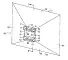
- FIGS. 1-4depict a first embodiment of an irradiation apparatus 30 in accordance with the present invention.
- Apparatus 30includes a first radiation source 32 and a substantially identical second radiation source 34 , each of which is depicted as an elongated discharge bulb.
- each radiation source 32 , 34might be a six-inch long, 2400-watt ultraviolet lamp, while in a higher power apparatus each source might be a 10 inch long, 6-kilowatt ultraviolet lamp.
- Radiation source 32is positioned within an elongated elliptical reflecting trough 36
- radiation source 34is positioned within a substantially identical trough 38 .
- Each trough 36 , 38preferably is substantially one half of an ellipse, although each trough could be less or more than one half an ellipse if desired.
- Radiation sources 32 and 34irradiate a relatively large planar target surface 40 .
- the longitudinal axes of radiation sources 32 and 34define a plane which is substantially parallel to planar target surface 40 .
- the ellipse of first trough 36has a first focal point within the trough.
- the locus of the first focal point along the length of trough 36thus defines a first focal axis 42 of the trough.
- the ellipse of first trough 36has a second focal point outside the trough, the locus of which defines a second focal axis 44 .
- the ellipse of second trough 38has a first focal point within the trough, the locus of which defines a first focal axis 46 of trough 38 . Further, the ellipse of second trough 38 has a second focal point outside the trough, the locus of which defines a second focal axis 48 .
- Each radiation source 32 , 34is spaced from the corresponding first focal axis 42 , 46 at positions that result in optimum two-dimensional uniformity of the radiation distribution on target surface 40 . By way of example, this might be a position toward target surface 40 by about ten percent of the focal length of the trough.
- each radiation source 32 , 34is mounted within its respective reflecting trough 36 , 38 by an adjustable mount 37 , 39 permitting adjustment of the position of each radiation source relative to the first focal axis of its respective elliptical reflecting trough, so as to optimize the uniformity of the radiation distribution on target surface 40 .
- FIG. 3depicts radiation sources 32 and 34 positioned between focal axes 42 and 46 and target 40 , the radiation sources could be on the side of the focal axes that is further from the target surface if such positions result in optimum uniformity of the radiation reaching the target surface.
- each radiation source 32 , 34is on the major axis of the ellipse of its respective trough 36 , 38 .
- Trough 36terminates in an outer or first longitudinal edge 50 and an inner or second longitudinal edge 52 .
- trough 38terminates in outer or first longitudinal edge 54 and inner or second longitudinal edge 56 .
- a top reflector 58extends from outer longitudinal edge 50 of first trough 36 to an end edge 51 which extends along the top edge of planar target surface 40 .
- a bottom reflector 60extends from outer longitudinal edge 54 of second trough 38 to an end edge 53 which extends along the bottom edge of planar target surface 40 .
- a first side reflector 62extends from the first transverse edges 61 , 63 of troughs 36 and 38 to an end edge 55 which extends along a first side edge of target surface 40 .
- a second side reflector 64extends from the second transverse edges 65 , 67 of troughs 36 and 38 to an end edge 57 which extends along the second side edge of target surface 40 .
- reflectors 58 - 64are pivotally connected to troughs 36 and 38 to permit accommodation of various sizes of target surfaces.
- the edges of the top and bottom reflectors 58 , 60 and the side reflectors 62 , 64may be joined by flexible, rolled, or telescoping reflective material, if desired, to accommodate such pivoting.
- the space between second longitudinal edges 52 and 56 of first trough 36 and second trough 38is closed by a further reflector 66 .
- a first inner reflector 68extends from inner or second longitudinal edge 52 of first trough 36
- a second inner reflector 70extends from the inner or second edge 56 of second trough 38
- Reflectors 68 and 70might extend to or beyond the respective second focal axes 44 and 48 , as desired, to obtain optimum uniformity of the radiation distribution on target surface 40
- First inner reflector 68might extend substantially parallel with bottom reflector 60
- second inner reflector 70might extend substantially parallel with top reflector 58 .
- preferably inner reflectors 68 and 70are pivotally connected to inner longitudinal edges 52 and 56 to permit angular adjustment of the reflectors relative to the troughs so as to further optimize the uniformity of the radiation distribution on planar target surface 40 .
- first trough 36may be mounted within a first housing 72 and second trough 38 mounted within a similar second housing 74 .
- Housings 72 and 74are adjustably mounted on supports 76 , permitting movement of the troughs and radiation sources.
- troughs 36 and 38together with elongated discharge bulbs 32 and 34 , are depicted as having their longitudinal axes extending horizontally, the axes could extend vertically or at an angle, if desired.
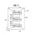
- FIGS. 5, 6 , and 7depict a second embodiment of an apparatus for providing substantially two-dimensionally uniform irradiation of a planar target surface in accordance with the present invention.
- FIGS. 5, 6 , and 7are respectively a rear perspective view, a schematic sectional view and a front elevational view of apparatus 80 .
- the top plan view of apparatus 80is substantially the same as FIG. 2 .
- Apparatus 80 of FIGS. 5-7differs from apparatus 30 of FIGS. 1-4 by having three radiation sources 82 , 84 , 86 mounted within respective elongated elliptical reflecting troughs 88 , 90 , 92 . Radiation from sources 82 , 84 , 86 is directed toward a planar target surface 94 .
- Apparatus 80includes top and bottom reflectors 96 and 98 , which extend from the first or outer longitudinal edges of troughs 88 and 92 to the top and bottom edges of target surface 94 , and first and second side reflectors 100 and 102 , which extend from the first and second transverse edges of troughs 88 , 90 , and 92 to the first and second side edges of target surface 94 .
- a first inner reflector 104is mounted on the second or inner longitudinal edge of trough 88 .
- a second inner reflector 106is mounted on the first longitudinal edge of trough 84
- a third inner reflector 108is mounted on the second longitudinal edge of trough 84 .
- a fourth inner reflector 110is mounted on the second or inner longitudinal edge of trough 92 .
- reflectors 96 - 102are pivotally mounted to troughs 88 - 92 so as to accommodate target surfaces of different sizes.
- reflectors 104 - 110are pivotally mounted to the troughs to allow angular adjustment of the inner reflectors relative to the troughs so as to permit further optimization of the uniformity of the radiation distribution on target surface 94 .
- Radiation source 84 and its trough 90are positioned substantially centrally of target surface 94 in the direction transverse to the longitudinal axis of the reflecting trough.
- Troughs 88 and 92 and their radiation sources 82 and 86are preferably movable in the direction of the minor axes of the troughs, for example by being mounted within housings 112 and 114 , respectively, with these housings adjustably mounted on supports 116 . This permits further optimization of the uniformity of the radiation of target surface 94 .
- the space between trough 88 and trough 90 and the space between trough 90 and trough 92are closed by further reflectors 118 , which might telescope to accommodate movement of troughs 88 and 92 as housings 112 and 114 move along supports 116 .
- the use of three radiation sources in respective troughsimproves the uniformity of the radiation distribution on target 94 .
- the uniformitycan be further optimized by adjustment of the distance of the radiation sources from the elliptical axes of the respective troughs, the positions of troughs 88 and 92 and radiation sources 82 and 86 , and the adjustment of the angular positions of inner reflectors 104 - 110 .
- the apparatus 30includes first and second elongated irradiation sources 32 and 34 , each of which is a ten inch, six-kilowatt tubular microwave powered ultraviolet discharge bulb.
- Each source 32 , 34is in an associated elongated elliptical reflecting trough 36 , 38 .
- Each troughis one-half of an ellipse having a major axis of approximately six inches and a minor axis of approximately four and one-fourth inches.
- Each radiation source 32 , 34is positioned on the major axis of the ellipse of its respective trough approximately 0.1 inch from its respective first focal axis 42 , 46 , which is a position found to provide optimum uniformity of radiation distribution on target surface 40 .
- Target surface 40is a 24 inch by 24 inch photosensitive film located approximately 24 inches from edges 50 - 56 of troughs 36 and 38 .
- Reflectors 68 and 70are pivoted to further optimize the uniformity of the radiation distribution.
- FIG. 8depicts the horizontal or X direction distribution of the radiation reaching target 40
- FIG. 9depicts the vertical or Y direction distribution. The X and Y directions are shown in FIG. 4 . As can be seen from FIGS. 8 and 9, the distribution of the radiation is substantially uniform.
- Each radiation source 82 , 84 , 86is a ten inch, six-kilowatt tubular microwave powered ultraviolet discharge bulb.
- Each bulb 82 , 84 , 86is in an associated elongated elliptical reflecting trough 88 , 90 , 92 , the ellipse of which had a major axis of approximately six inches and a minor axis of approximately four and one-fourth inches.
- Troughs 88 and 92together with their radiation sources 82 and 86 , are positioned at locations approximately two-thirds of the distance from the center of trough 90 toward top reflector 96 and bottom reflector 98 , respectively.
- Each radiation sourceis positioned on the major axis of its associated trough at a location found to provide optimum uniformity to the radiation distribution on target surface 94 .
- Reflectors 104 - 110are pivoted so as to further optimize the uniformity of the radiation distribution on target surface 94 .
- the target surfaceis a photosensitive film which extends 24 inches in the X direction and 48 inches in the Y direction and is positioned approximately 24 inches from troughs 88 - 92 .
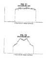
- the X and Y directionsare shown in FIG. 7 .
- FIG. 10depicts the horizontal or X direction distribution of the radiation reaching target surface 94
- FIG. 11depicts the vertical or Y direction distribution. As can be seen from FIGS. 10 and 11, the radiation distribution on target surface 94 is
- the simulated apparatus of Example 2is adjusted by moving troughs 88 and 92 approximately one-fourth inch outward (i.e. toward top and bottom reflecting surfaces 96 and 98 , respectively), as compared with the position of Example 2.
- Radiation sources 82 , 84 , and 86are positioned within the troughs, and inner reflectors on 104 - 110 are pivoted so as to provide optimum uniformity to the radiation distribution on target surface 94 .
- FIGS. 12 and 13depict respectively the X direction radiation distribution and the Y direction radiation distribution. As can be seen, the radiation distribution is substantially uniform.
- the simulated apparatus of Example 2is adjusted by moving troughs 88 and 92 approximately one-half inch toward top reflector 96 and bottom reflector 98 , respectively, as compared with the positions of Example 2. Again the radiation sources are positioned within the troughs, and the inner reflectors are pivoted to provide optimum uniformity to the radiation distribution on target surface 94 .
- FIGS. 14 and 15depict, respectively, the X direction distribution and the Y direction distribution. Again, it can be seen that the distribution is substantially uniform.
- Example 2The apparatus of Example 2 is adjusted by moving troughs 88 and 92 approximately one-half inch inward from the positions of Example 2 (i.e. one half inch further from top reflector 96 and bottom reflector 98 , respectively).
- the radiation sourcesare positioned within the troughs and the inner reflectors are pivoted to provide optimum uniformity to the radiation distribution on target surface 94 .
- FIGS. 16 and 17depict, respectively, the X direction radiation distribution and the Y direction radiation distribution on target surface 94 . Once more it can be seen that the distribution is substantially uniform.
- FIGS. 18-20are respectively a perspective view, a schematic sectional view, and a front elevational view of apparatus 130 .
- the top plan viewis substantially the same as FIG. 2 .
- Apparatus 130includes an elongated radiation source 132 positioned within an elongated elliptical reflecting trough 134 .
- a top reflector 136extends from one longitudinal edge of trough 134 to a top edge of a target surface 138 .
- Target surface 138is a 24 inch by 24 inch photosensitive film positioned 24 inches from trough 134 .
- a bottom reflector 140extends from the second longitudinal edge of trough 134 to a bottom edge of target surface 138 .
- First and second side reflectors 142 and 144extend from the sides of trough 134 to the sides of target surface 138 .
- Radiation source 132is a ten inch, six-kilowatt ultraviolet electrodeless discharge bulb.
- Trough 134is one-half of an ellipse having a major axis of approximately six inches and minor axis of approximately four and one-fourth inches.
- Radiation source 132is positioned on the major axis at the location found to provide optimum achievable uniformity of the radiation distribution on target surface 138
- FIG. 21depicts the horizontal or X direction distribution of the radiation reaching target surface 138
- FIG. 22depicts the vertical or Y direction distribution.
- the X and Y directionsare shown in FIG. 20 . While the X direction distribution is somewhat uniform, the Y direction distribution is clearly non-uniform.
- Both the apparatus of FIGS. 1-4 and the apparatus of FIGS. 5-7provide improved two-dimensional uniformity of radiation distribution on a planar target surface, compared with the apparatus of FIGS. 18-20.
- the present inventionis an apparatus and method providing uniform irradiation of large areas with a high level of radiation.
Landscapes
- Physics & Mathematics (AREA)
- Engineering & Computer Science (AREA)
- Plasma & Fusion (AREA)
- Apparatus For Disinfection Or Sterilisation (AREA)
- Physical Or Chemical Processes And Apparatus (AREA)
- Treatments Of Macromolecular Shaped Articles (AREA)
Abstract
Description
Claims (74)
Priority Applications (3)
| Application Number | Priority Date | Filing Date | Title |
|---|---|---|---|
| US10/196,954US6797971B2 (en) | 2002-07-18 | 2002-07-18 | Apparatus and method providing substantially two-dimensionally uniform irradiation |
| AU2003249376AAU2003249376A1 (en) | 2002-07-18 | 2003-06-27 | Apparatus and method providing substantially two-dimensionally uniform irradiation |
| PCT/US2003/020067WO2004010221A2 (en) | 2002-07-18 | 2003-06-27 | Apparatus and method providing substantially two-dimensionally uniform irradiation |
Applications Claiming Priority (1)
| Application Number | Priority Date | Filing Date | Title |
|---|---|---|---|
| US10/196,954US6797971B2 (en) | 2002-07-18 | 2002-07-18 | Apparatus and method providing substantially two-dimensionally uniform irradiation |
Publications (2)
| Publication Number | Publication Date |
|---|---|
| US20040011969A1 US20040011969A1 (en) | 2004-01-22 |
| US6797971B2true US6797971B2 (en) | 2004-09-28 |
Family
ID=30442867
Family Applications (1)
| Application Number | Title | Priority Date | Filing Date |
|---|---|---|---|
| US10/196,954Expired - LifetimeUS6797971B2 (en) | 2002-07-18 | 2002-07-18 | Apparatus and method providing substantially two-dimensionally uniform irradiation |
Country Status (3)
| Country | Link |
|---|---|
| US (1) | US6797971B2 (en) |
| AU (1) | AU2003249376A1 (en) |
| WO (1) | WO2004010221A2 (en) |
Cited By (4)
| Publication number | Priority date | Publication date | Assignee | Title |
|---|---|---|---|---|
| US20050123287A1 (en)* | 2003-12-04 | 2005-06-09 | Micropyretics Heaters International, Inc. | Flexible die heater |
| US20060292311A1 (en)* | 2005-06-28 | 2006-12-28 | Kilburn John I | UV cure equipment with combined light path |
| US20100154244A1 (en)* | 2008-12-19 | 2010-06-24 | Exfo Photonic Solutions Inc. | System, Method, and Adjustable Lamp Head Assembly, for Ultra-Fast UV Curing |
| US20110233425A1 (en)* | 2008-09-29 | 2011-09-29 | Nederlandse Organisatie voor toegepst-natuurwetens chappelijk onderzoek TNO | device and a method for curing patterns of a substance at a surface of a foil |
Families Citing this family (3)
| Publication number | Priority date | Publication date | Assignee | Title |
|---|---|---|---|---|
| WO2009046586A1 (en)* | 2007-10-13 | 2009-04-16 | He Shan Lide Electronic Enterprise Company Ltd. | A method of providing light distribution, a cup for providing light distribution, and a roadway lamp using the cup |
| US9599397B2 (en)* | 2010-08-30 | 2017-03-21 | Ncc Nano, Llc | Light curing apparatus having a modular lamp housing |
| DE102010044244A1 (en)* | 2010-09-02 | 2012-03-08 | Khs Gmbh | Method and device for treating containers |
Citations (28)
| Publication number | Priority date | Publication date | Assignee | Title |
|---|---|---|---|---|
| US4010374A (en) | 1975-06-02 | 1977-03-01 | Ppg Industries, Inc. | Ultraviolet light processor and method of exposing surfaces to ultraviolet light |
| US4048490A (en) | 1976-06-11 | 1977-09-13 | Union Carbide Corporation | Apparatus for delivering relatively cold UV to a substrate |
| US4276479A (en) | 1974-04-01 | 1981-06-30 | Japan Storage Battery Co., Ltd. | Apparatus for curing photo-curable composition |
| US4297583A (en) | 1979-02-08 | 1981-10-27 | American Can Company | Ultraviolet light apparatus |
| US4348105A (en) | 1981-04-30 | 1982-09-07 | Rca Corporation | Radiation shadow projection exposure system |
| US4503086A (en) | 1983-08-22 | 1985-03-05 | Adolph Coors Company | Device and method for uniformly curing uv photoreactive overvarnish layers |
| US4726949A (en) | 1986-08-26 | 1988-02-23 | Baxter Travenol Laboratories, Inc. | Irradiation of blood products |
| US4812957A (en) | 1985-07-23 | 1989-03-14 | Fusion Systems Corporation | Optical system for uniform illumination of a plane surface |
| US4948980A (en)* | 1988-07-20 | 1990-08-14 | Wedeco Gesellschaft Fur Entkeimungsanlagen M.B.H. | Apparatus for irradiating media with UV-light |
| US5130553A (en) | 1990-09-13 | 1992-07-14 | Ushio Denki Kabushiki Kaisha | Apparatus for forming aesthetic artificial nails |
| US5133932A (en) | 1988-03-29 | 1992-07-28 | Iatros Limited | Blood processing apparatus |
| US5176782A (en) | 1990-12-27 | 1993-01-05 | Orc Manufacturing Company, Ltd. | Apparatus for photochemically ashing a photoresist |
| US5211467A (en) | 1992-01-07 | 1993-05-18 | Rockwell International Corporation | Fluorescent lighting system |
| US5269867A (en) | 1990-10-26 | 1993-12-14 | Canon Kabushiki Kaisha | Method for producing optical device |
| US5440137A (en) | 1994-09-06 | 1995-08-08 | Fusion Systems Corporation | Screw mechanism for radiation-curing lamp having an adjustable irradiation area |
| US5494576A (en) | 1992-06-15 | 1996-02-27 | Pollution Management Industries | System and method for treating water |
| US5635133A (en) | 1995-08-30 | 1997-06-03 | Glazman; Mark | Method and apparatus for killing microorganisms in a fluid medium |
| US5699185A (en) | 1990-11-09 | 1997-12-16 | Litel Instruments | Use of fresnel zone plates for material processing |
| US5760408A (en) | 1995-12-08 | 1998-06-02 | Siemens Audiologische Technik Gmbh | Semiconductor exposure device |
| US5817276A (en) | 1997-02-20 | 1998-10-06 | Steril-Aire U.S.A., Inc. | Method of UV distribution in an air handling system |
| US5839078A (en) | 1995-07-26 | 1998-11-17 | British Nuclear Fuels Plc | Waste processing method and apparatus |
| US5898809A (en) | 1997-09-19 | 1999-04-27 | Taboada; John | Projecting a sheet of laser light such as a laser reference plane using a fiber optic bundle |
| US5922605A (en) | 1996-05-08 | 1999-07-13 | Ivoclar Ag | Polymerization apparatus and method for controlling polymerization apparatus |
| US5932886A (en) | 1996-03-27 | 1999-08-03 | Ushiodenki Kabushiki Kaisha | Ultraviolet irradiation device |
| US5973331A (en) | 1996-08-02 | 1999-10-26 | Nordson Corporation | Lamp assembly |
| US6124600A (en) | 1997-05-27 | 2000-09-26 | Ushiodenki Kabushiki Kaisha | Ultraviolet irradiation device of the optical path division type |
| US6190016B1 (en) | 1997-10-29 | 2001-02-20 | Ushiodenki Kabushiki Kaisha | Irradiation device for an alignment layer of a liquid crystal cell element |
| US6323601B1 (en)* | 2000-09-11 | 2001-11-27 | Nordson Corporation | Reflector for an ultraviolet lamp system |
- 2002
- 2002-07-18USUS10/196,954patent/US6797971B2/ennot_activeExpired - Lifetime
- 2003
- 2003-06-27AUAU2003249376Apatent/AU2003249376A1/ennot_activeAbandoned
- 2003-06-27WOPCT/US2003/020067patent/WO2004010221A2/ennot_activeApplication Discontinuation
Patent Citations (29)
| Publication number | Priority date | Publication date | Assignee | Title |
|---|---|---|---|---|
| US4276479A (en) | 1974-04-01 | 1981-06-30 | Japan Storage Battery Co., Ltd. | Apparatus for curing photo-curable composition |
| US4010374A (en) | 1975-06-02 | 1977-03-01 | Ppg Industries, Inc. | Ultraviolet light processor and method of exposing surfaces to ultraviolet light |
| US4048490A (en) | 1976-06-11 | 1977-09-13 | Union Carbide Corporation | Apparatus for delivering relatively cold UV to a substrate |
| US4297583A (en) | 1979-02-08 | 1981-10-27 | American Can Company | Ultraviolet light apparatus |
| US4348105A (en) | 1981-04-30 | 1982-09-07 | Rca Corporation | Radiation shadow projection exposure system |
| US4503086A (en) | 1983-08-22 | 1985-03-05 | Adolph Coors Company | Device and method for uniformly curing uv photoreactive overvarnish layers |
| US4812957A (en) | 1985-07-23 | 1989-03-14 | Fusion Systems Corporation | Optical system for uniform illumination of a plane surface |
| US4726949A (en) | 1986-08-26 | 1988-02-23 | Baxter Travenol Laboratories, Inc. | Irradiation of blood products |
| US5133932A (en) | 1988-03-29 | 1992-07-28 | Iatros Limited | Blood processing apparatus |
| US4948980A (en)* | 1988-07-20 | 1990-08-14 | Wedeco Gesellschaft Fur Entkeimungsanlagen M.B.H. | Apparatus for irradiating media with UV-light |
| US5130553A (en) | 1990-09-13 | 1992-07-14 | Ushio Denki Kabushiki Kaisha | Apparatus for forming aesthetic artificial nails |
| US5269867A (en) | 1990-10-26 | 1993-12-14 | Canon Kabushiki Kaisha | Method for producing optical device |
| US5699185A (en) | 1990-11-09 | 1997-12-16 | Litel Instruments | Use of fresnel zone plates for material processing |
| US5176782A (en) | 1990-12-27 | 1993-01-05 | Orc Manufacturing Company, Ltd. | Apparatus for photochemically ashing a photoresist |
| US5211467A (en) | 1992-01-07 | 1993-05-18 | Rockwell International Corporation | Fluorescent lighting system |
| US5494576A (en) | 1992-06-15 | 1996-02-27 | Pollution Management Industries | System and method for treating water |
| US5440137A (en) | 1994-09-06 | 1995-08-08 | Fusion Systems Corporation | Screw mechanism for radiation-curing lamp having an adjustable irradiation area |
| US5839078A (en) | 1995-07-26 | 1998-11-17 | British Nuclear Fuels Plc | Waste processing method and apparatus |
| US5635133A (en) | 1995-08-30 | 1997-06-03 | Glazman; Mark | Method and apparatus for killing microorganisms in a fluid medium |
| US5760408A (en) | 1995-12-08 | 1998-06-02 | Siemens Audiologische Technik Gmbh | Semiconductor exposure device |
| US6128030A (en) | 1995-12-08 | 2000-10-03 | Sony Corporation | Semiconductor exposure device |
| US5932886A (en) | 1996-03-27 | 1999-08-03 | Ushiodenki Kabushiki Kaisha | Ultraviolet irradiation device |
| US5922605A (en) | 1996-05-08 | 1999-07-13 | Ivoclar Ag | Polymerization apparatus and method for controlling polymerization apparatus |
| US5973331A (en) | 1996-08-02 | 1999-10-26 | Nordson Corporation | Lamp assembly |
| US5817276A (en) | 1997-02-20 | 1998-10-06 | Steril-Aire U.S.A., Inc. | Method of UV distribution in an air handling system |
| US6124600A (en) | 1997-05-27 | 2000-09-26 | Ushiodenki Kabushiki Kaisha | Ultraviolet irradiation device of the optical path division type |
| US5898809A (en) | 1997-09-19 | 1999-04-27 | Taboada; John | Projecting a sheet of laser light such as a laser reference plane using a fiber optic bundle |
| US6190016B1 (en) | 1997-10-29 | 2001-02-20 | Ushiodenki Kabushiki Kaisha | Irradiation device for an alignment layer of a liquid crystal cell element |
| US6323601B1 (en)* | 2000-09-11 | 2001-11-27 | Nordson Corporation | Reflector for an ultraviolet lamp system |
Cited By (8)
| Publication number | Priority date | Publication date | Assignee | Title |
|---|---|---|---|---|
| US20050123287A1 (en)* | 2003-12-04 | 2005-06-09 | Micropyretics Heaters International, Inc. | Flexible die heater |
| US8131138B2 (en)* | 2003-12-04 | 2012-03-06 | Micropyretics Heaters International, Inc. | Flexible die heater |
| US20060292311A1 (en)* | 2005-06-28 | 2006-12-28 | Kilburn John I | UV cure equipment with combined light path |
| US7638780B2 (en) | 2005-06-28 | 2009-12-29 | Eastman Kodak Company | UV cure equipment with combined light path |
| US20110233425A1 (en)* | 2008-09-29 | 2011-09-29 | Nederlandse Organisatie voor toegepst-natuurwetens chappelijk onderzoek TNO | device and a method for curing patterns of a substance at a surface of a foil |
| US8395135B2 (en)* | 2008-09-29 | 2013-03-12 | Nederlandse Organisatie Voor Toegepast-Natuurwetenschappelijk Onderzoek Tno | Device and a method for curing patterns of a substance at a surface of a foil |
| US20100154244A1 (en)* | 2008-12-19 | 2010-06-24 | Exfo Photonic Solutions Inc. | System, Method, and Adjustable Lamp Head Assembly, for Ultra-Fast UV Curing |
| US10267563B2 (en) | 2008-12-19 | 2019-04-23 | Excelitas Canada, Inc. | System, method, and adjustable lamp head assembly, for ultra-fast UV curing |
Also Published As
| Publication number | Publication date |
|---|---|
| AU2003249376A8 (en) | 2009-05-14 |
| AU2003249376A1 (en) | 2004-02-09 |
| WO2004010221A3 (en) | 2009-04-16 |
| WO2004010221A2 (en) | 2004-01-29 |
| US20040011969A1 (en) | 2004-01-22 |
Similar Documents
| Publication | Publication Date | Title |
|---|---|---|
| US6649921B1 (en) | Apparatus and method providing substantially two-dimensionally uniform irradiation | |
| US7847269B2 (en) | Apparatus for and method of treating a fluid | |
| US4019062A (en) | Unit for treatment of substrate with ultraviolet radiation | |
| US6797971B2 (en) | Apparatus and method providing substantially two-dimensionally uniform irradiation | |
| CN112351841A (en) | Reflector providing uniform light energy | |
| WO2004098699A2 (en) | Apparatus and method providing substantially uniform irradiation of surfaces of elongated objects with a high-level of irradiance | |
| CA2556749C (en) | Combined ablation and exposure system and method | |
| US6566660B1 (en) | UV dryer for curing multiple surfaces of a product | |
| CN1266546C (en) | Apparatus for exposing the surface of a printed circuit board | |
| KR101728532B1 (en) | Apparatus of exposure for scan type using LED light source | |
| JPH06198162A (en) | Ultraviolet irradiating device | |
| JPH05265220A (en) | Exposure device for inclined substrate | |
| JP2002170415A (en) | Light irradiation device | |
| US7055990B2 (en) | Apparatus and method for providing substantially uniform radiation of a three-dimensional object with at least one curved surface | |
| JPS62143426A (en) | Light irradiation device | |
| WO1998036889A1 (en) | Apparatus for the photo-initiated chemical cross-linking of material | |
| JPH09265802A (en) | Lighting equipment | |
| KR102439341B1 (en) | surface light-emitting device | |
| EP0493691A1 (en) | Ultraviolet light irradiation device in painting plants using photopolymerizable paints | |
| SU1341448A1 (en) | Radiation source for exposure of photopolymerizing plates | |
| JPH02168505A (en) | Irradiation device | |
| JP2014026038A (en) | Ultraviolet irradiation device | |
| CN114935827A (en) | Device for improving UV irradiation uniformity | |
| JPS5666879A (en) | Magnification variable copying machine | |
| RU98106726A (en) | METHOD FOR CUTTING AND COAGULATION OF BIOLOGICAL TISSUE OF ABDOMINAL CAVITY |
Legal Events
| Date | Code | Title | Description |
|---|---|---|---|
| AS | Assignment | Owner name:FUSION UV SYSTEMS, INC., MARYLAND Free format text:ASSIGNMENT OF ASSIGNORS INTEREST;ASSIGNORS:CEKIC, MIODRAG;GELLER, BORIS;REEL/FRAME:013115/0359 Effective date:20020711 | |
| STCF | Information on status: patent grant | Free format text:PATENTED CASE | |
| REMI | Maintenance fee reminder mailed | ||
| FPAY | Fee payment | Year of fee payment:4 | |
| SULP | Surcharge for late payment | ||
| FPAY | Fee payment | Year of fee payment:8 | |
| FEPP | Fee payment procedure | Free format text:PAYOR NUMBER ASSIGNED (ORIGINAL EVENT CODE: ASPN); ENTITY STATUS OF PATENT OWNER: LARGE ENTITY | |
| AS | Assignment | Owner name:HERAEUS NOBLELIGHT FUSION UV INC., MARYLAND Free format text:CHANGE OF NAME;ASSIGNOR:FUSION UV SYSTEMS, INC.;REEL/FRAME:030745/0476 Effective date:20130201 | |
| AS | Assignment | Owner name:HERAEUS NOBLELIGHT AMERICA LLC, MARYLAND Free format text:CHANGE OF NAME;ASSIGNOR:HERAEUS NOBLELIGHT FUSION UV INC.;REEL/FRAME:035021/0864 Effective date:20141212 | |
| FPAY | Fee payment | Year of fee payment:12 | |
| AS | Assignment | Owner name:HERAEUS NOBLELIGHT FUSION UV INC., MARYLAND Free format text:CORRECTIVE ASSIGNMENT TO CORRECT THE INCORRECT PATENT NO. 7606911 PREVIOUSLY RECORDED AT REEL: 030745 FRAME: 0476. ASSIGNOR(S) HEREBY CONFIRMS THE CHANGE OF NAME;ASSIGNOR:FUSION UV SYSTEMS, INC.;REEL/FRAME:038401/0806 Effective date:20130201 |