US6796715B2 - Fiber optic modules with pull-action de-latching mechanisms - Google Patents
Fiber optic modules with pull-action de-latching mechanismsDownload PDFInfo
- Publication number
- US6796715B2 US6796715B2US09/939,413US93941301AUS6796715B2US 6796715 B2US6796715 B2US 6796715B2US 93941301 AUS93941301 AUS 93941301AUS 6796715 B2US6796715 B2US 6796715B2
- Authority
- US
- United States
- Prior art keywords
- fiber optic
- optic module
- actuator
- pull
- pivot
- Prior art date
- Legal status (The legal status is an assumption and is not a legal conclusion. Google has not performed a legal analysis and makes no representation as to the accuracy of the status listed.)
- Expired - Lifetime, expires
Links
Images


Classifications
- G—PHYSICS
- G02—OPTICS
- G02B—OPTICAL ELEMENTS, SYSTEMS OR APPARATUS
- G02B6/00—Light guides; Structural details of arrangements comprising light guides and other optical elements, e.g. couplings
- G02B6/24—Coupling light guides
- G02B6/36—Mechanical coupling means
- G02B6/38—Mechanical coupling means having fibre to fibre mating means
- G02B6/3807—Dismountable connectors, i.e. comprising plugs
- G02B6/381—Dismountable connectors, i.e. comprising plugs of the ferrule type, e.g. fibre ends embedded in ferrules, connecting a pair of fibres
- G02B6/3825—Dismountable connectors, i.e. comprising plugs of the ferrule type, e.g. fibre ends embedded in ferrules, connecting a pair of fibres with an intermediate part, e.g. adapter, receptacle, linking two plugs
- G—PHYSICS
- G02—OPTICS
- G02B—OPTICAL ELEMENTS, SYSTEMS OR APPARATUS
- G02B6/00—Light guides; Structural details of arrangements comprising light guides and other optical elements, e.g. couplings
- G02B6/24—Coupling light guides
- G02B6/36—Mechanical coupling means
- G02B6/38—Mechanical coupling means having fibre to fibre mating means
- G02B6/3807—Dismountable connectors, i.e. comprising plugs
- G02B6/3897—Connectors fixed to housings, casing, frames or circuit boards
- G—PHYSICS
- G02—OPTICS
- G02B—OPTICAL ELEMENTS, SYSTEMS OR APPARATUS
- G02B6/00—Light guides; Structural details of arrangements comprising light guides and other optical elements, e.g. couplings
- G02B6/24—Coupling light guides
- G02B6/42—Coupling light guides with opto-electronic elements
- G02B6/4292—Coupling light guides with opto-electronic elements the light guide being disconnectable from the opto-electronic element, e.g. mutually self aligning arrangements
- G—PHYSICS
- G02—OPTICS
- G02B—OPTICAL ELEMENTS, SYSTEMS OR APPARATUS
- G02B6/00—Light guides; Structural details of arrangements comprising light guides and other optical elements, e.g. couplings
- G02B6/24—Coupling light guides
- G02B6/36—Mechanical coupling means
- G02B6/38—Mechanical coupling means having fibre to fibre mating means
- G02B6/3807—Dismountable connectors, i.e. comprising plugs
- G02B6/389—Dismountable connectors, i.e. comprising plugs characterised by the method of fastening connecting plugs and sockets, e.g. screw- or nut-lock, snap-in, bayonet type
- G02B6/3893—Push-pull type, e.g. snap-in, push-on
- G—PHYSICS
- G02—OPTICS
- G02B—OPTICAL ELEMENTS, SYSTEMS OR APPARATUS
- G02B6/00—Light guides; Structural details of arrangements comprising light guides and other optical elements, e.g. couplings
- G02B6/24—Coupling light guides
- G02B6/42—Coupling light guides with opto-electronic elements
- G02B6/4201—Packages, e.g. shape, construction, internal or external details
- G02B6/4246—Bidirectionally operating package structures
Definitions
- This inventionrelates generally to fiber optic modules. More particularly, the invention relates to release mechanisms for unplugging fiber optic modules.
- Fiber optic modulescan transduce electrical data signals in order to transmit optical signals over optical fibers. Fiber optic modules can also transduce optical signals received over optical fibers into electrical data signals.
- the size or form factor of fiber optic modulesis important. The smaller the form factor of a fiber optic module, the less space taken on a printed circuit board to which it couples. A smaller form factor allows a greater number of fiber optic modules to be coupled onto a printed circuit board to support additional communication channels. However, the smaller form factor makes it more difficult for a user to handle.
- a typical release method for a pluggable fiber optic moduleis to push in on the fiber optic module itself and then pull out on the fiber optic module to release it from a cage assembly or module receptacle. It has been determined that this method is not very reliable with users complaining of the difficulty in removing pluggable fiber optic modules in this manner.
- the pushing and then pulling of traditional methodsplaces extra strain on components of the fiber optic module itself, the cage assembly or module receptacle and any electrical connections which the fiber optic module makes with an electrical connector. Oftentimes more than one cycle of pushing and pulling on the fiber optic module is required to release it from the cage or receptacle.
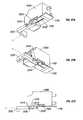
- FIG. 1is a simplified top-exploded view illustrating an optical element.
- FIG. 2is a partially assembled view of an optical element, receiver printed circuit board, and transmitter printed circuit board.
- FIG. 3is an exploded view of a printed circuit board cage subassembly and optical element.
- FIG. 4Ais an exploded view from the rear of an embodiment of a hot pluggable fiber optic module.
- FIG. 4Bis a magnified view of a side of a male electrical connector to provide hot pluggability.
- FIG. 4Cis a magnified view of another side of the male electrical connector to provide hot pluggability.
- FIG. 5is exploded view from the front of an embodiment of a fiber optic module.
- FIG. 6Ais a top view of an embodiment of an assembled fiber optic module.
- FIG. 6Bis a bottom view of an embodiment of an assembled fiber optic module.
- FIG. 6Cis a right side view of an embodiment of an assembled fiber optic module.
- FIG. 6Dis a left side view of an embodiment of an assembled fiber optic module.
- FIG. 6Eis a front view of an embodiment of an assembled fiber optic module.
- FIG. 6Fis a rear view of an embodiment of an assembled fiber optic module.
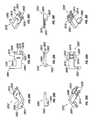
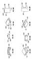
- FIGS. 7A-7Dare views of a disassembled fiber optic module of embodiments of the invention.
- FIGS. 7E-7Fare perspective views of a disassembled fiber optic module of another embodiment of the invention illustrating an alternate embodiment of a withdrawal tab.
- FIGS. 7G-7Hare perspective views of a disassembled fiber optic module of another embodiment of the invention illustrating another alternate embodiment of a withdrawal tab.
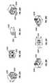
- FIGS. 8A-8Gare various views of an embodiment of a withdrawal tab for fiber optic modules.
- FIGS. 9A-9Iare various views of an embodiment of a kicker-actuator for fiber optic modules.
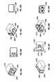
- FIGS. 10A-10Gare views of a subassembly of the fiber optic modules of Figures 7 A- 7 D illustrating the pull-actuator of FIGS. 8A-8G and the kicker-actuator of FIGS. 9A-9I assembled to the nose receptacle
- FIGS. 11A-11Eare views of an exemplary cage assembly or module receptacle for fiber optic modules.
- FIG. 12is a bottom view of a system of the push button releasable fiber optic module engaged with the exemplary cage assembly or module receptacle for FIGS. 11A-11E.
- FIGS. 13A-13Bare cross-section views of the system of FIG. 12 with the push button release in a latched or steady state.
- FIGS. 14A-14Bare cross-section views of the system of FIG. 12 with the push button release depressed and delatching the fiber optic module from the cage assembly or receptacle module.
- FIG. 15is a flow chart diagram of a method of releasing a fiber-optic module.
- FIG. 16is a flow chart diagram of a method of inserting a fiber-optic module.
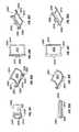
- FIG. 17Ais a perspective view of a fiber optic system with a belly-to-belly mounting configuration with the top fiber optic module removed.
- FIG. 17Bis a side view of the fiber optic system with a belly-to-belly mounting configuration of FIG. 17 A.
- FIG. 17Cis a side view of the fiber optic system with a belly-to-belly mounting configuration of FIG. 17A with the top fiber optic module inserted.
- FIG. 17Dis a cross-section view of the fiber optic system with a belly-to-belly mounting configuration of FIG. 17C with the top fiber optic module inserted.
- FIGS. 18A-18Dillustrate various views of a subassembly of a pair of fiber optic modules in a belly to belly mounting configuration.
- FIGS. 19A-19Fillustrate various views of an integrated push button actuator for another embodiment of the invention.
- FIGS. 20A-20Dillustrate various magnified views of the integrated push button actuator of FIGS. 19A-19F.
- FIGS. 21A-21Dillustrate various views of alternate push button embodiments for the actuators.
- FIGS. 22A-22Hillustrate various views of a subassembly of a nose receptacle and pull-actuator for another embodiment of the invention.
- FIG. 23illustrates a pull-actuator, pivot-arm actuator, and cage assembly latch for one embodiment of the invention.
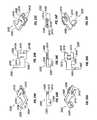
- FIGS. 24A-24Iillustrate various views of a pull-actuator for one embodiment of the invention.
- FIGS. 25A-25Iillustrate various views of a pivot-arm actuator for one embodiment of the invention.
- FIGS. 26A-26Cillustrate various cross-sectional views of an integrated nose assembly and latching mechanism of FIGS. 24A-24I and 25 A- 25 I in the engaged position for one embodiment of the invention.
- FIGS. 27A-27Cillustrate various cross-sectional views of an integrated nose assembly and latching mechanism of FIGS. 24A-24I and 25 A- 25 I in the disengaged position for one embodiment of the invention.
- FIGS. 28A-28Iillustrate various views of a pull-actuator for another embodiment of the invention.
- FIGS. 29A-29Iillustrate various views of a pivot-arm actuator including a spring for another embodiment of the invention.
- FIGS. 30A-30Cillustrate various cross-sectional views of an integrated nose assembly and latching mechanism of FIGS. 28A-I and 29 A-I in the engaged position for one embodiment of the invention.
- FIGS. 31A-31Cillustrate various cross-sectional views of an integrated nose assembly and latching mechanism of FIGS. 28A-I and 29 A-I in the disengaged position for one embodiment of the invention.
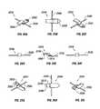
- FIGS. 32A-32Iillustrate various views of alternative embodiments of pull mechanisms for pull-actuators.
- FIGS. 33A-33Dillustrate various views of a belly-to-belly mounting configuration for another embodiment of the invention employing pull-actuators.
- FIGS. 34A-34Iillustrate various views of a subassembly of a nose receptacle including a bail latch delatching mechanism for another embodiment of the invention.
- FIGS. 35A-35Iillustrate various views of a bail latch including a pivoting pin for one embodiment of the invention.
- FIGS. 36A-36Iillustrate various views of an actuator for one embodiment of the invention.
- FIGS. 37A-37Eillustrate various cross-sectional views of an integrated nose assembly and latching mechanism of FIGS. 34A-34I in the engaged position for one embodiment of the invention.
- FIGS. 38A-38Eillustrate various cross-sectional views of an integrated nose assembly and latching mechanism of FIGS. 34A-34I in the disengaged position for one embodiment of the invention.
- FIGS. 39A-39Hillustrate various views of an alternate embodiments of the bail latch.
- FIGS. 40A-40Iillustrate various views of how the bail-latch delatching mechanism would function in a belly-to-belly mounting configuration for another embodiment of the invention.
- a “fiber-optic transceiver”is a fiber optic module having optical signal transmit and receive capability.
- the terms “disengage”, “release”, “unlatch”, and “de-latch”may be used interchangeably when referring to the de-coupling of a fiber optic module from a cage assembly.
- the inventionincludes methods, apparatuses and systems for fiber optic modules including pull-action releasable fiber optic modules in small form pluggable (SFP) GBIC, LC type packages.
- SFPsmall form pluggable
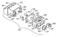
- the optical element 103included a nose 151 , a pair of fiber ferrule sleeves 131 , an electromagnetic interference (EMI) shield plate 153 , an optical block 120 , a receiver 111 and a transmitter 110 .
- the electromagnetic interference shield plate 153provides shielding to keep electromagnetic interference from leaking into or out of the optical block 120 and the module.
- the optical block 120aligns a light transmitter 110 and a light receiver 111 with two lenses in the optical block 120 .
- the light transmitters 110 or light receivers 111are optoelectronic devices for communicating with optical fibers using light of various wavelengths or photons.
- An optoelectronic deviceis a device which can convert or transduce light or photons into an electrical signal or an electrical signal into light or photons.
- the light transmitters 110are packaged emitters that can convert electrical signals into light or photons. Examples of emitters are semiconductor lasers (i.e. a VCSEL) or an LED which may be packaged in TO (transistor outline) cans.
- the light receivers 111are packaged photodetectors, that detect or receive light or photons and convert it into an electrical signal.
- An example of a photo detectoris a photo diode which may be packaged in a TO can.
- housings or optoelectronic devices for receiving and transmitting light or photonsmay be used for the light transmitters 110 or light receivers 111 .
- the electromagnetic interference plate 153has one or more projections 156 which engage one or more external notches 157 of the optical block 120 near its edges.
- the optical ports 159 of the electromagnetic interference plate 153align with a pair of optical ports 129 and 130 of the nose 151 .
- the electromagnetic interference plate 153is electrically coupled to an outer housing 400 (shown on FIG. 5) via the projections 156 and shunts electro-magnetic fields to the outer housing 400 .
- the fiber ferules 131can be inserted into the optical ports 129 and 130 upon assembly.
- the nose 151further has one or more posts 164 over which one or more holes 158 in the electromagnetic interference plate 153 can slide in order to align the nose 151 , the pair of fiber ferules 131 , the electromagnetic interference plate 153 and the optical block 120 together.
- the nose 151has a pair of LC receptacles 161 for mechanically coupling and aligning a pair of fiber optic cables (not shown) into the fiber optic module 100 .
- Each LC receptacle 161is a fiber optic receptacle for one serial fiber optic channel.
- the LC receptacles 161 in the nose 151are preferably located without spacing between each other. Neighboring channels are separated far enough apart that a fiber optic module 100 having multiple channels can comply with FDA and IEC Class-1 eye safety limits. This eases handling of the fiber optic module 100 by avoiding the use of eye protection.
- TO-can size packagesare usable which allows the output power level of each individual fiber optic channel to be separately monitored.
- Monitoring a fiber optic channelinvolves splitting the light beam so that a photodetector or photodiode receives a portion of the light beam. The electrical output of the photodiode is then measured to indicate the output power level of the fiber optic channel.
- the relaxed spacing of the individual fiber optic receptacles of the inventionfacilitate placing light beam splitters within the TO can of the light transmitter 110 .
- the light beam splittersplits the beam such that a portion of the light beam lands on a photodiode within the TO can.
- the photodiode's outputis measured to monitor the output power of the transmitter.
- each channelcan be individually optimized.
- fiber optic connectorssuch as, but not limited to, SC, MT-RJ, VF 45 , and MU connectors, may be used in lieu of the LC receptacles 161 .
- Receiver printed circuit board 250includes one or more receiver electrical components 227 (receiver integrated circuit (transimpedance amplifier and post amplifier), resistors, capacitors and other passive or active electrical components), a male electrical connector 235 , and a receiver ground plane 213 (not shown).
- the transmitter printed circuit board 200includes one or more transmitter electrical components 229 (transmitter integrated circuit (laser driver), resistors, capacitors and other passive or active electrical components) and a transmitter ground plane 215 (not shown).
- the receiver printed circuit board 250 and the transmitter printed circuit board 200may be assembled by wave soldering.
- At least one pin of the male electrical connector 235couples to an external female electrical connector.
- the external female electrical connectorsmay be SFP (Small Form Pluggable) SMT (Surface Mount Technology) connectors.
- One or more pins of the male electrical connector 235allow electrical signals, power, and ground to be coupled into or out of the fiber optic module 100 .
- FIG. 3an exploded view of the optical element 103 , the receiver printed circuit board 250 , the transmitter printed circuit board 200 , a bottom frame 301 , and a top frame 303 is illustrated.
- One or more transmitter pins 243 of the male electrical connector 235which couple to the transmitter electrical components 229 , the transmitter electrical components 229 , the light transmitter 110 , the interconnect leads 225 and a lens (not shown) of the optical block form one transmitting channel.
- the transmitter electrical components 229control the light transmitter 110 and buffer the data signal received from a system for transmission over an optical fiber.
- One or more receiver pins 245 of the male electrical connector 235which couple to the receiver electrical components 227 , the receiver electrical components 227 , the light receiver 111 and a lens (not shown) of the optical block form one receiving channel.
- the receiver electrical components 227control the light receiver 111 and buffer the data signal received from an optical fiber.
- Other combinations of componentscan form other combinations of communications channels.
- the optical element 103includes the light receiver 111 with a plurality of straddle mount signal leads 201 .
- the Straddle mount signal leads 201are arranged in two horizontal rows to straddle a printed circuit board.
- the two rows of straddle mount signal leads 201sandwich the receiver printed circuit board 250 so that the straddle mount signal leads 201 electrically couple the light receiver 111 to a plurality of receiver contacts 203 on both sides of the receiver printed circuit board 250 .
- soldermay be applied to the straddle mount signal leads 201 and the receiver contacts 203 .
- the receiver contacts 203are preferably a metal such as copper, silver, gold or other metal or alloy.
- the receiver contacts 203may be on one or both the top and bottom surfaces of the receiver printed circuit board 250 .
- Optical element 103has a light transmitter 110 with a plurality of formed (i.e. bent) signal leads 205 .
- Each formed signal lead 205is bent and turned up to couple to a header signal via 207 , in the printed circuit board.
- the printed circuit board 250has a cutout 209 that allows space for a horizontal portion of the formed signal lead 205 .
- the cutout 209may be at an angle cutting out a corner of receiver printed circuit board 250 . In the alternative, the cutout 209 may be a square, semicircle, quarter circle or other shape.
- the vertical portion of each formed signal lead 205is long enough to couple the light transmitter 110 to the transmitter printed circuit board 200 .
- formed signal leads 205couple to a plurality of vias 207 , through-holes, contacts or other coupling devices on the transmitter printed circuit board 200 .
- soldermay be applied to the formed signal lead 205 and the via 207 . Since the printed circuit board assemblies and optical elements are mechanically coupled after the printed circuit boards have been wave soldered, the optical elements are not subject to the heat generated by wave soldering. While a 90 degree angle has been described, it is understood that other arrangements of the formed signal leads 205 may be employed to couple the light transmitter 110 to the transmitter printed circuit board 200 .
- the receiver printed circuit board 250 and the transmitter printed circuit board 200When assembled into the fiber optic module, the receiver printed circuit board 250 and the transmitter printed circuit board 200 are vertically stacked and substantially parallel to each other.
- the top frame 303 and the bottom frame 301hold the receiver printed circuit board 250 and the transmitter printed circuit board 200 in fixed vertical and horizontal alignment.
- the fiber optic modulefurther includes one or more interconnect leads 225 which electrically couple the transmitter electrical components 229 on the transmitter printed circuit board 200 to transmitter pins 243 of the electrical connector by means of signal traces in the receiver printed circuit board 250 .
- the receiver printed circuit board 250includes a receiver ground plane 213 (shown in FIG. 2 ), and the transmitter printed circuit board 200 includes a transmitter ground plane 215 (shown in FIG. 2 ).
- Receiver ground plane 213shunts electromagnetic fields radiating into it to ground via a pin in the male electrical connector 235 .
- the transmitter ground plane 215shunts electro-magnetic fields radiating into ground through one or more of the interconnect leads 225 , a transmitter trace 247 on the receiver printed circuit board 250 , and a pin 243 in the male electrical connector 235 .
- the receiver printed circuit board 250includes a pair of slots 231 (referred to as receiver slots 231 ) one in the left side edge and another in the right side edge of the printed circuit board as shown and illustrated in FIG. 2 .
- the transmitter printed circuit board 200includes a pair of slots 233 (referred to as transmitter slots 233 ) one in the left side edge and another in the right side edge of the printed circuit board as shown and illustrated in FIG. 2 .
- the receiver slots 231 and the transmitter slots 233facilitate alignment between the receiver printed circuit board 250 and the transmitter printed circuit board 200 .
- the bottom frame 301includes a pair of sides 341 A and 341 B, a base 343 , a pair of rails 305 A and 305 B, a plurality of lower support tabs 335 and a plurality of upper support tabs 337 extending from a pair of corners of each of the sides 341 A and 341 B as illustrated in FIG. 3 .
- the base 343 of the bottom frame 301is L shaped such that the rail 305 B extends along the side and base of the bottom frame 301 while the rail 305 B extends out of a center line (near the middle of the bottom frame) with a surface of the base there-between.
- the L shapeleaves a cutout area from the base of the bottom frame which will be filled in by a bottom cover as described below.
- the rail 305 A extending from the center line or middle of the bottom frame 301includes a tip 355 A that extends outward and is inserted into an opening 155 in the optical block 120 .
- the top frame 303includes a top 347 , a pair of top frame sides 349 A and 349 B, a pair of alignment rails 307 , and a flange 321 as shown and illustrated in FIG. 3 .
- the receiver printed circuit board 250When assembled, the receiver printed circuit board 250 is inserted into a pair of slots 309 between the upper support tabs and the lower support tabs and rests on the lower support tabs 335 of the bottom frame 301 .
- a pair of receiver slots 231 in edges of the receiver printed circuit board 250are located near corners of the sides 341 A and 341 B of the receiver printed circuit board.
- the four lower support tabs 335 and the four upper support tabs 337restrict vertical movement in the receiver printed circuit board 250 when its engaged thereto.
- One or more of the elements of the bottom frame 301may be formed of a conductive material such as a metal or formed to include a conductive plating or surface.
- the conductive material of the bottom frame 301shunts electromagnetic fields to ground via an electrical coupling to chassis ground. In this manner the bottom frame 301 can provide electromagnetic interference shielding for the fiber optic module.
- the transmitter printed circuit board 200When assembled, the transmitter printed circuit board 200 rests on the four upper support tabs 337 of the bottom frame 301 such that the pair of transmitter slots 233 in the transmitter printed circuit board 200 are aligned directly above the pair of receiver slots 231 in the receiver printed circuit board 250 at a position adjacent to and above the upper support tabs 337 .
- the alignment of the slots 233 with the slots 231 in each of the respective printed circuit boardsassures that the transmitter interconnect vias 239 align with the receiver interconnect vias 241 such that the one or more interconnect leads 225 can be coupled there-between.
- the one or more interconnect leads 225couple the respective transmitter traces 247 in the transmitter printed circuit board 200 and the receiver printed circuit board 250 together.
- the interconnect leads 225are soldered to the receiver printed circuit board 250 at the receiver interconnect vias 241 on one end and to the transmitter printed circuit board 200 at the transmitter interconnect vias 239 at an opposite end. Though the interconnect leads 225 have been described as providing electrical coupling between the receiver printed circuit board 250 and the transmitter printed circuit board 200 , it is understood that other interconnect devices may be employed including ribbon cable, wires, male and female electrical connectors and the like.
- the pair of top frame sides 349 A and 349 B of the top frame 303engage with the bottom frame sides 341 A and 341 B of the bottom frame 301 respectively when they are assembled together. When assembled, external faces of the top frame sides 349 abut inside faces of bottom frame sides 341 .
- Each of the top frame sideshave a pair of locking tabs 313 which engage with a pair of lock tab apertures 315 in each of the bottom frame sides 341 to hold them together.
- the locking tabs 313 and the locking tab apertures 315prevent the bottom frame 301 and the top frame 303 from moving vertically relative to each other.
- the top frame 303has the pair of alignment rails 307 on edges of the top frame sides 349 A and 349 B.
- the alignment rails 307mate with the pair of transmitter slots 233 in the transmitter printed circuit board 200 and the pair of the receiver slots 231 in the receiver printed circuit board 250 to keep them in alignment so that the interconnect leads 225 are not sheared by movement in either and the electrical coupling is maintained.
- Top frame 303has a tab 363 , rib, post or other member on the underside of top 347 .
- top frame 303When top frame 303 is assembled to the bottom frame 301 and transmitter board 200 , the tab 363 prevents upward movement of transmitter printed circuit board 200 . Additionally, the pair of alignment rails 307 abut a pair of lower support tabs 335 and a pair of upper support tabs 337 to maintain alignment and avoid movement as stress is placed on the receiver printed circuit board 250 when the fiber optic module is pulled away from a connector.
- the top frame 303includes the flange 321 which extends from the top 347 of the top frame 303 as shown and illustrated in FIG. 3 .
- the flange 321includes an opening 317 which slides over a top post 319 of the optical block 120 of the optical element 103 .
- the top frame 303When the opening 317 of the flange 321 is mated with the top post 319 , the top frame 303 is tightly coupled to the optical element 103 to avoid separation when the fiber optic module is inserted or removed from a connector. With the opening 317 engaged to the top post 319 so that the top frame is tightly coupled, the alignment rails 307 of the top frame 303 in conjunction with the receiver slots 231 and the transmitter slots 233 , keep the receiver printed circuit board 250 and the transmitter printed circuit board 200 tightly coupled to the optical element 103 as well to avoid separation.
- the flange 321includes a flange lip 325 that abuts a recess wall 327 of the optical block 120 to prevent lateral movement of the top frame 303 relative to the optical elements 103 .
- the top frame 303includes a pair of top frame sides 349 A and 349 B and the top 347 . These and other elements of the top frame may be formed of a conductive material such as a metal or formed to include a conductive plating or surface. The conductive material of the top frame 303 shunts electro-magnetic fields to ground via an electrical coupling to chassis ground. In this manner, the top frame 303 provides electromagnetic interference shielding to the fiber optic module.
- the assembled subassembly including the receiver printed circuit board 250 , the transmitter printed circuit board 200 , the interconnect leads 225 , the bottom frame 301 and the top frame 303can hereinafter be referred to as a printed circuit board assembly 411 .
- the outer housing 400includes a top cover 401 , a bottom cover 402 and the L shaped bottom frame 301 .
- the top cover 401 , the bottom cover 402 and the bottom frame 301couple together and around the optical block 120 to encase the receiver and transmitter printed circuit boards but for one end where the extension in the receiver printed circuit board forms the male connector 235 .
- the top cover 401includes a top portion and a pair of sides that fit over the printed circuit board assembly 411 and the optical element 103 .
- the top cover 401includes a plurality of locating tab openings 405 in each of its sides to engage with locating tabs 407 in sides of the optical block 120 , in the nose of optical element 103 , and in the bottom frame 301 .
- the top cover 401includes a hood 409 which encloses an end of the transmitter printed circuit board 200 but leaves the connector 235 of the receiver printed circuit board 250 exposed to connect to a connector.
- the male electrical connector 235extends from the top cover 401 to mechanically and electrically couple to an external female electrical connector.
- the bottom cover 402is of sufficient size to fill into the cutaway area in the L shaped bottom frame 301 .
- the bottom cover 402couples to the bottom frame 301 on one side and the top cover 401 on an opposite side.
- the male electrical connector 235includes one or more ground or negative power pins 460 , one or more positive power pins 461 and one or more signal pins 462 on top and/or bottom surfaces of the receiver printed circuit board 250 .
- the pins 460 , 461 , and 462are staggered from each other with reference to an edge 465 of the receiver printed circuit board 250 to facilitate the hot pluggability.
- the ground pins 460 of the male electrical connector 235are closer to the edge 465 than any other pin in the male electrical connector 235 in order for ground to be established first when the fiber optic module is inserted and for ground to be removed last when its removed.
- the positive power pins 461are next closest to the edge 465 for power to be established secondly when the fiber optic module is inserted and for power to be removed next to last when its removed.
- the signal pins 462are farther from the edge that the power pins 461 and ground pins 462 so that they are established after power and ground has been when inserted and they are disconnect first when the fiber optic module is removed.
- the ground pinselectrically couple first to ground receptacles of the external female electrical connector in order to ground the fiber optic module 100 .
- the ground pinelectrically decouples from the ground last to maintain the grounding of the fiber optic module 100 until after power is removed from the fiber optic module 100 .
- the ground pins 460being closer to the edge 465 than the power pins 461 and the signal pins 462 , prevents damage and disruption to the fiber optic module and the system during the physical insertion and removal of the fiber optic module into and out of the system.
- the capability to physically remove and insert the fiber optic module during operation without damage or disruptionis referred to as hot pluggability.
- the outer housing 400may be formed of a conductive material such as a metal or include a conductive plating or surface. With the outer housing 400 formed out of a conductive material, the outer housing 400 can shunt electromagnetic fields radiating into the outer housing 400 to ground via an electrical coupling to chassis ground. In this manner the outer housing 400 also can provide electromagnetic interference shielding to the fiber optic module.
- the bottom cover 402 of the outer housing 400includes a pair of tabs 509 on one side and a pair of projections 505 on an opposite side.
- the projections 505 of the one sideengage a pair of holes 507 in a side of the rail 305 A of the bottom frame 301 .
- the projections 505 in the opposite side of the bottom cover 402engage the housing holes 511 in a side of the top cover 401 .
- the inside surface of the side of the top cover 401couples to the outer surface of the side of the bottom cover 402 when the tabs 509 are mated with the housing holes 511 .
- the bottom cover 402can be readily disassembled and reassembled with the top cover 401 and the bottom frame 301 of the fiber optic module 100 . By removing the bottom cover 402 , a portion of the receiver printed circuit board is exposed to allow access to adjust adjustable electrical components (not shown) on the receiver printed circuit board 250 .
- the adjustable electrical componentselectrically couple to the electrical components 227 on the receiver printed circuit board 250 .
- the adjustable electrical componentselectrically couple to the electrical components 229 by way of a conductive path through one or more transmitter traces 361 on the receiver printed circuit board 250 , the interconnect vias 225 , and the transmitter traces 247 on the transmitter printed circuit board 200 .
- the adjustable electrical componentsmay include DIP switches, potentiometers, variable capacitors and other devices used to tune or adjust the performance of the fiber optic module 100 .
- the bottom cover 402can also be formed of a conductive material such as a metal or include a conductive plating or surface which is coupled to chassis ground (via holes 507 , housing holes 511 and tabs 505 and projections 509 ) in order to provide electromagnetic interference shielding for the fiber optic module 100 .
- FIG. 6Aillustrates a top view of a fully assembled fiber optic module 100 .
- FIG. 6Billustrates a bottom view of a fully assembled fiber optic module 100 .
- FIG. 6Cillustrates a right side view of a fully assembled fiber optic module 100 .
- FIG. 6Dillustrates a left side view of a fully assembled fiber optic module 100 .
- FIG. 6Cillustrates a front view of a fully assembled fiber optic module.
- FIG. 6Dillustrates a rear view of a fully assembled fiber optic module 100 .
- the receiver printed circuit board 250is first slid into the slots 309 of the bottom frame 301 between the upper support tabs 337 and the lower support tabs 335 until the receiver slots 231 are adjacent to, and just inside an end of the bottom frame 301 .
- receiver electrical components 227are face down, the ground plane is face up and the male electrical connector 235 extends beyond the end of the bottom frame 301 so that its external thereto.
- the one or more interconnect leads 225are then press fit into the receiver interconnect vias 241 . Solder is applied to the interconnect leads 225 at the receiver interconnect vias 241 .
- the transmitter interconnect vias 239 of the transmitter printed circuit board 200are aligned with the one or more interconnect leads and press fit together so that the transmitter printed circuit board rests on top of the upper support tabs 337 .
- the ground planeis facing down toward the receiver printed circuit board while the transmitter electrical components 229 are on the face up side on the surface of the transmitter printed circuit board 200 and opposite the receiver printed circuit board 250 .
- solderis applied to the interconnect leads 225 at the transmitter interconnect vias 239 .
- the top frame 303is next in the assembly process.
- the alignment rails 307 of the top frame 303are aligned with the transmitter slots 233 and the receiver slots 231 .
- the alignment rails 107are inserted into the transmitter slots 233 so that external surfaces of the sides 349 A and 349 B slide into the internal surfaces of the sides 341 A and 341 B respectively.
- the top frame 303is coupled to the bottom frame such that the alignment rails 107 slide through the transmitter slots 233 and the receiver slots 231 until the locking tabs 313 engage with the lock tab apertures 315 to lock the top frame 303 in place relative to the bottom frame 301 .
- the optical elements 103are prepared in parallel with forming the printed circuit board assembly 411 .
- a die(not shown) is used to bend the signal leads of the light transmitter 110 through 90 degrees to form the formed signal leads 205 of the invention.
- the optical elementsare then assembled and aligned together as a subassembly 103 .
- the printed circuit board subassembly 411is then coupled together to the optical elements subassembly 103 .
- the printed circuit board subassembly 411is positioned with the optical elements so that the receiver contacts 203 of the receiver printed circuit board 250 align with the space between the horizontal rows of straddle mount signal leads 201 .
- the flange 321 of the top frame 303is flexed upward so that the opening 317 can mate with the post 319 .
- the printed circuit board subassembly 411 and optical element 103are brought together so that the receiver contacts 203 can electrically be couple to the straddle mount signal leads 201 and the tip 355 A slides into the opening 155 .
- the flange 321is then released so that the opening 317 slides over the top post 319 to secure the printed circuit board subassembly 411 to the optical element subassembly 103 .
- the outer housing 400is completed around the printed circuit board subassembly 411 .
- the top cover 311is aligned with the printed circuit board subassembly 411 so that the locating tab openings 405 can mate with the locating tabs 407 .
- the top cover 401is slid over the optical element subassembly 103 and the printed circuit board subassembly 411 so that the locating tabs 407 snap into the locating tab openings 405 .
- the bottom cover 402is then couple to the bottom frame 301 and the top cover 401 .
- the bottom coveris tilted so that the projections 505 engage the holes 507 in the side of the rail of the bottom frame 301 .
- the top cover 402is pressed upward so that the tabs 509 engage with the housing holes 511 so that the bottom cover 402 is secured in place to complete the assembly of the fiber optic module 100 .
- the fiber optic module 100electrically functions such that external electrical transmitter signals arriving at transmitter pins 243 in the male electrical connector 235 are coupled into the transmitter traces 247 routed on the receiver printed circuit board 250 .
- the transmitter traces 247couple the external electrical transmitter signal from the transmitter pins 243 to the receiver interconnect vias 241 .
- the receiver interconnect vias 241couple the transmitter signals to the one or more interconnect leads 225 .
- the one or more interconnect leads 225couple the electrical signals from the receiver interconnect vias 241 at one end into the transmitter interconnect vias 239 at an opposite end.
- the transmitter traces 247 on the transmitter printed circuit board 200couple the electrical signals from the transmitter interconnect vias 239 into the transmitter electrical components 229 and/or the transmitter 110 .
- the transmitter electrical components 229process the electrical signals into electrical transmission pulses for coupling to the light transmitter 110 .
- the light transmitter 110transduces the electrical transmission pulses into light pulses for transmission over the fiber optic cables.
- the fiber optic module 100electrically functions such that external light pulses arriving at the LC receptacles 161 are transduced into electrical pulses by the light receiver 111 for coupling into the receiver electrical components 227 .
- the receiver electrical components 227process the electrical pulses into electrical receiver signals which are coupled to the receiver traces 249 of the receiver printed circuit board 250 .
- the receiver traces 249couple the receiver signals to the receiver pins 245 in the male electrical connector 235 by which the electrical receiver signals are coupled to external devices.
- one electrical component on one of the printed circuit boardscontrols both the light transmitter 110 and the light receiver 111 .
- the fiber optic module 100may be housed in a rack or a cabinet designed to house an LC, GBIC package.
- the male electrical connector 235couples to a female electrical connector of the rack or cabinet.
- one or more ground pins in the male electrical connector 235electrically couples to one or more corresponding ground receptacles in the female electrical connector before any other pin electrically couples.
- One or more power pins in the male electrical connector 235electrically couple to one or more corresponding power receptacles in the female electrical connector before any signal pins electrically couple.
- one or more signal pinsmay then electrically couple to one or more corresponding signal receptacles.
- fiber optical cablesare connected to the LC receptacles 161 .
- the inventionallows hot pluggable replacement.
- the moduleis disconnected from any electrical connector into which it is coupled.
- the signal pinsdecouple first, the power pins second and the ground pins last. After which a new fiber optic module 100 can be inserted with the connecting sequence occurring as discussed above.
- the optical element subassembly 103 or the printed circuit board subassembly 411may be easily replaced.
- the flange 321is flexed up to demate the opening 317 and the top post 319 .
- the optical subassembly 103is then pulled away from the printed circuit board assembly 411 .
- the straddle mount signal leads 201decouple from the receiver contacts 203 .
- the formed signal leads 205also decouple from the header signal vias 207 .
- a replacement optical subassemblyis then coupled to the printed circuit board assembly 411 as discussed above. After which the fiber optic module 100 (the replacement optical element 103 coupled to the printed circuit board assembly 411 ) can be inserted with the connecting sequence occurring as discussed above.
- the fiber optic moduleis removed as discussed above, except that the fiber optic cables need not be removed from the LC receptacles 161 .
- the flange 321is flexed up to demate the opening 317 and the top post 319 .
- the optical element 103is then pulled away from the printed circuit board assembly.
- the straddle mount signal leads 201decouple from the receiver contacts 203 .
- the formed signal leads 205also decouple from the header signal vias 207 .
- a replacement printed circuit board assembly 411is then coupled to the optical element 103 as discussed above. After which the fiber optic module 100 (the optical element 103 coupled to the replacement printed circuit board assembly 411 ) can be inserted with the connecting sequence occurring as discussed above.
- the fiber optic module 100may include two or more combinations of vertically stacked receivers, or transmitters, or receivers and transmitters.
- One embodiment of the inventionincludes four vertically stacked transmitters.
- Another embodimentincludes four vertically stacked receivers.
- Yet another embodimentincludes a combination of four vertically stacked transmitters and receivers.
- the transmitter printed circuit board 200has the cutout 209 creating a distance 211 for the formed signal leads 205 of the light receiver 111 .
- the formed signal leads 205 of the light receiver 111couple to the header signal vias 207 on receiver printed circuit board 250 .
- the straddle mount signal leads 201 of the light transmitter 110couple to contacts on the transmitter printed circuit board 200 .
- the electrical components 227 and 229are on opposite surfaces of the printed circuit boards 250 and 200 so that the ground planes 213 and 215 provide electromagnetic shielding to the electrical components 227 and 229 .
- the transmitter printed circuit board 200includes the male electrical connector 235 .
- Receiver traces 249 of the transmitter printed circuit board 200couple receiver pins 245 of the male electrical connector 235 to the interconnect vias 225 .
- the interconnect vias 225couple the receiver traces 249 of the transmitter printed circuit board 200 to receiver traces 249 of receiver printed circuit board 250 for coupling to receiver electrical components 227 .
- the transmitter printed circuit board 200also includes a portion that protrudes from the outer housing 400 and that includes the male electrical connector 235 , thereby allowing the male electrical connector 235 to couple to an external female electrical connector.
- One aspect of the inventionprovides a push-button release mechanism and easy withdrawal mechanism for removable or pluggable fiber optic modules which are coupled into a module receptacle or cage assembly. Additionally, a piggy-back or belly-to-belly fiber optic module configuration is provided.
- the quick releaseis a mechanical device for de-latching or unplugging a fiber optic module from a module receptacle or cage assembly.
- the inventionis particularly applicable to de-latching or unplugging an SFP fiber optic module from an SFP cage assembly or module receptacle.
- the inventionprovides a set of mechanical devices designed to enhance the de-latching and withdrawing process of removable or pluggable fiber optic modules from cages or receptacles.
- the mechanical devicesinclude three main components consisting of (1) a kicker-actuator, (2) a withdrawal tab, and (3) a nose grip.
- the pluggable fiber optic moduleis de-latched or unlatched and unplugged from any sockets or connectors of the cage or module receptacle.
- Fiber optic module 700is a pluggable or removable type of fiber optic module in that it can slide in and out into a cage or receptacle having a electrical connector and coupled there to or decoupled therefrom.
- the pluggable fiber optic module 700is push button releasable and includes an electro-optical sub-assembly 701 and a mechanical sub-assembly 701 and a mechanical sub-assembly 702 .
- the mechanical sub-assembly 702couples to the optical block 120 of the electro optical sub-assembly 701 .
- the fiber optic module 700is an SFP module and the cage assembly or module receptacle into which it plugs is an SFP cage assembly or SFP module receptacle.
- the fiber optic module incorporating the inventioncan be any type of pluggable fiber optic module.
- the mechanical sub-assembly 702includes a nose receptacle 704 , a kicker-actuator 705 (also referred to as push button), an actuator 706 , a withdraw tab 708 with an optional pull grip 709 .
- the kicker-actuator 705serves as an extension arm to the actuator 706 .
- the actuator 706is an SFP actuator.
- the nose receptaclereceives one or more fiber optic connectors from which an optical fiber may be attached.
- the nose receptacle 704aligns ends of the fiber optic cables with optical openings therein.
- the nose receptacle 704is an SFP receptacle to receive a duplex SFP fiber optic connector.
- the bottom side of the nose receptacle 704includes a boss 1002 , an opening 745 having a pair of tangs 741 on opposite sides thereof and a rib or septum 747 .
- the catch or boss 1002interfaces to a latch of the cage or receptacle.
- the opening 745 in the nose receptacle 704is for slideably engaging with the actuator 706 for releasing the boss 1002 from a latch and freeing the fiber optic module from a cage or receptacle.
- the actuatorwhen assembled slides over the rib or septum 747 .
- the rib or septum 747can provide slideable support to the actuator 706 to allow it to push out on the latch while the tangs can provide slideable guidance in movement of the kicker-actuator 705 and the actuator 706 .
- FIGS. 7C and 7Dprovide additional top and bottom views of the disassembled fiber optic module 700 illustrated from a different angle.
- the actuator 706includes one or more ramps or wedges (a pair of which are illustrated) 1308 , slot or grooves 721 on each side having an opening at one end and a closure at an opposite end.
- the slot or grooves 721slideably engage the tangs 741 in the nose receptacle 704 .
- the kicker-actuator 705has a hook 902 to hook onto the actuator 706 by mechanical means.
- the actuator 706includes an opening 707 into which the hook 902 of the kicker actuator 705 may couple in order to couple them together.
- the nose receptacle 704includes a nose grip 714 at its sides, alignment pins 715 and optical openings 716 at a front side and one or more fiber plug openings 717 at a back side.
- the nose grip 714has a left side 714 L and a right side 714 R including vertical ribs near the front around the openings of the fiber optic receptacles.
- the nose gripserves as the additional gripping area during the withdrawal process of the fiber optic module.
- the nose grip 714includes one or more vertical ribs on the nose receptacle. The one or more vertical ribs increase pressure between gripping fingers and hence prevent slippage during handling.
- the nose grip 714is an integrated part of the nose receptacle 704 and can be formed of similar materials.
- FIGS. 7E-7Fillustrate an alternate fiber optic module 700 ′ having an alternate embodiment of a withdrawal tab 708 ′.
- the fiber optic moduleincludes the alternate mechanical subassembly 702 ′ with the alternate withdrawal tab 708 ′.
- the withdrawal tab 708 described with reference to FIGS. 7A-7Dwas coupled to the nose receptacle and extended across the top surface of the fiber optic module 700 .
- a userwould pull on the withdrawal tab 708 , extending across the top surface or plane of the fiber optic module, to withdraw the fiber optic module.
- the withdrawal tab 708 ′couples between the optical block and the nose receptacle and extends from the bottom surface of the fiber optic module 700 ′.
- the withdrawal tab 708 ′includes a pull area 709 ′ that may optionally include a pull grip, a pair of arms 724 joined around an opening 725 and an EMI shield or plate 756 .
- the opening 725provides for the kicker-actuator 705 and the actuator 706 to extend through it and slide back and forth in the nose receptacle 704 when assembled together.
- the EMI shield or plate 756includes optical openings and alignment openings similar to the EMI shield 806 discussed further below and includes one or more grounding tabs 788 .
- the withdrawal tab 708 ′may be non-conductive and not include the grounding tabs 788 .
- FIGS. 7G-7Hillustrate an alternate fiber optic module 700 ′′ having an alternate embodiment of a withdrawal tab 708 ′′.
- the fiber optic moduleincludes the alternate mechanical subassembly 702 ′′ with the alternate withdrawal tab 708 ′′.
- the withdrawal tab 708 described with reference to FIGS. 7A-7Dcoupled to the nose receptacle at the top of the fiber optic module 700 and a user pulled from the top.
- the withdrawal tab 708 ′′couples between the optical block and the nose receptacle and extends from one or both sides of the fiber optic module 700 ′′.
- a userpulls on the withdrawal tab 708 ′′ from one or both sides of the fiber optic module to pull it out from a cage or receptacle.
- the withdrawal tab 708 ′′includes one or two pull areas 709 ′′ that may optionally include a pull grip, a left pull arm 734 L, a right pull arm 734 R or both, and an EMI shield or plate 766 .
- the EMI shield or plate 766includes optical openings and alignment openings similar to the EMI shield 806 discussed further below and includes one or more grounding tabs 788 .
- the withdrawal tab 708 ′′may be non-conductive and not include the grounding tabs 788 .
- the withdrawal tab 708may include an arm 804 , an EMI shield 806 , and grounding tabs 808 .
- the EMI shield 806can be replaced by a similar shaped non-conductive plate without grounding tabs 808 .
- the withdrawal tab 708may also be referred to as a pull actuator.
- the withdrawal tab 708has a paddle area 802 coupled to the arm 804 which couples to the optional pull grip 709 .
- the withdrawal tab 708is a flexible protruding handle that serves as the pull-out tab for users during the withdrawal of the fiber optic module.
- the withdraw tab 708extends out from the fiber optic module to provide an easy reach and grip to a user.
- the withdrawal tab 708may further include the optional pull grip 709 to prevent slippage during handling.
- the optional pull grip 709may be formed of a rubber or plastic material.
- the arm 804can be flexed or folded up with minimal effort. Additionally, the arm 804 avoids the withdrawal tab from obstructing optical connectors during the insertion of the fiber optic module.
- the arm 804can be formed out of sheet metal, rubber sheet or plastic sheet materials.
- the optional pull grip 709can be injection molded by using a rubber or plastic resin.
- the withdrawal tab 708can itself provide an EMI shield 806 , a vertical component, that rests between a nose receptacle 704 and an optical block or port 120 (as shown in FIGS. 10 A- 10 E).
- the EMI shield 806has a shielding ability to cut off EMI emitting from the front of the nose receptacle of the fiber optic module.
- the EMI shield 806includes one to four grounding tabs 808 that provide additional guarding of EMI emission around the EMI shield.
- the grounding tabs 808also provide grounding links or contacts between the EMI Shield 806 and the cage assembly or module receptacle. In typical cases, the cage assembly or module receptacle is grounded.
- the EMI shield 806includes alignment pin openings 812 to allow alignment pins 715 of the nose receptacle 704 to poke through.
- the EMI shield 806further includes a first optical opening 814 for a first opto-electronic device and a second optical opening 816 for a second opto-electronic device.
- One of the optical openingsmay be larger than the other to allow for an entrance angle of light or photons for a receiving opto-electronic device.
- the kicker-actuator 705is illustrated in detail.
- the kicker-actuator 705is also referred to as a push button.
- the kicker-actuator 705includes a snap on hook 902 , an arm or push rod 904 , and an offset push tab or button 906 .
- the offset push tab or button 906can include an orientation indicator 908 .
- the offset push tab or button 906is offset of the center of the push rod 904 to provide clearance for belly-to-belly mounting configurations described further below.
- the hook 902is at one end of the arm while the off set push tab 906 is at the opposite end of the arm 904 .
- the push rod 904can include a depression so that it clears a corner of the nose receptacle during assembly.
- the subassembly of the actuator 706 and kicker-actuator 705are inserted into the nose receptacle 704 on an angle and snapped into place to slideably engage the nose receptacle 704 .
- the kicker-actuator 705can be formed out of epoxy, thermoplastic, rubber or metal.
- the off-set push tab 906is characterized by its L-shape cross-section.
- the snap-on-hook 902is a locking mechanism for securing the kicker-actuator 705 on the actuator 706 .
- the orientation indicator 908is arrow-shaped on the front face of the off-set-push tab 906 to indicate which fiber optic module it releases.
- an assembled mechanical sub-assembly 702is assembled together with the optical block 120 .
- the ground tabs( 808 L and 808 R) wrap around and onto the optical block 120 .
- the non-conductive plate of the withdrawal tabneeds no ground tabs.
- the kicker-actuator 705is coupled to the actuator 706 which is in turn coupled to the nose receptacle 704 .
- the snap on hook 902 of the kicker-actuator 705couples into the opening 707 of the actuator 706 . This is then snapped into the bottom side of the nose receptacle 704 .
- the kicker-actuator 705extends out from the front edge of the nose receptacle and thus is visible to end-users and as well as accessible so that it can be pushed inward.
- the kicker-actuator 705 and the actuator 706provide a de-latching mechanism for the fiber optic module 700 .
- a force exerted inward on the kicker-actuator 705is utilized to de-latch the fiber optic module 700 .
- the withdraw tab 708 and the nose grip ( 714 L and 714 R)provide a withdrawal mechanism for the fiber optic module 700 .
- FIGS. 11A-11Eviews of an exemplary cage assembly or module receptacle 1100 for fiber optic modules is illustrated.
- the latch 1102is illustrated in a bottom view of the module receptacle 1100 .
- the latch 1102includes a catch 1105 that mates with the hook or boss 1002 .
- the latch 1102is flexed downward in order to release the fiber optic module.
- the actuator 706flexes the latch 1102 downward when a force is exerted on the kicker-actuator or push button 705 .
- a ramp of the kicker-actuator 705meets a lip 1108 of the latch 1102 which is bent on an angle and then flexes the latch 1102 outward so that the catch 1105 is released from the hook or boss 1002 . This release mechanism and method is described further below.
- FIG. 12illustrates a bottom view showing the latch 1102 and the boss 1002 of the nose receptacle 704 .
- the boss 1002engages into the catch or opening 1105 of the latch 1102 .
- FIGS. 13A and 13Bcross sections of the fiber optic module 700 inserted into the cage or receptacle 1100 are illustrated.
- the boss 1002extends through the opening 1105 to be engaged with the latch 1102 .
- the kicker-actuator 705is in an un-pushed or steady state.
- the spring tension in the latch 1102tends to move the kicker-actuator 705 into this state.
- the actuator 706includes one or more ramps 1308 that engage the lip 1108 of the latch 1102 of the cage or receptacle 1100 .
- the ramps 1308slideably engage the lip 1108 and pushes out on the latch 1102 therefrom.
- a pair of ramps 1308are used so that they can slide over it and continue pressing out on the latch.
- FIGS. 14A and 14Bcross section similar to that of FIGS. 13A and 13B are illustrated but for the kicker-actuator 705 being depressed to disengage the latch 1102 from the boss 1002 .
- the opening 1105 of the latch 1102is not engaged with the boss 1002 of the nose receptacle.
- the kicker-actuator 705is pushed in or depressed.
- the kicker-actuator 705directs the actuator 706 to the de-latching position, allowing the fiber optic module 700 to be disengaged from the cage or receptacle 1100 .
- the kicker-actuator 705pushes in on the actuator 706 causing the one or more ramps 1308 to push out on the lip 1108 and release the latch 1102 from around the boss 1002 .
- the fiber optic module 700can be pulled out from the cage or receptacle 1100 .
- the fiber optic module 700can be pulled out by using the withdrawal tab 708 and/or the nose grip ( 714 L and 714 R).
- a flow chart diagramis illustrated of a method of releasing a fiber-optic module that includes an embodiment of the invention.
- the methodbegins at step 1500 (i.e. start) using a fiber-optic module, such as fiber optic module 700 for example, that includes an embodiment of the invention which is inserted into a module cage or receptacle, such as the cage or receptacle 1100 for example.
- the methodthen jumps to step 1502 .
- a userpushes in on the release push-button or kicker-actuator 705 disengaging the latch 1102 of the cage or receptacle 1100 from the boss 1002 of the fiber optic module 700 for example.
- step 1504the user then pulls out on the fiber-optic module using a pull mechanism such as the withdrawal tab 708 or the nose grip ( 714 L and 714 R) of the nose receptacle to begin pulling out the fiber optic module.
- step 1506a check is made whether the boss 1002 of the fiber optic module has cleared the key or latch 1102 . If past, the method jumps to step 1507 where a user continues to pull out on the fiber optic module until completely removed and the method ends at step 1508 . If not past the latch 1102 , the method jumps back to step 1502 where a user continues to push in on the release push button or kicker-actuator 705 and continues to pull out on the fiber optic module at step 1504 .
- FIG. 16a flow chart diagram is illustrated of a method of engaging a fiber-optic module that includes an embodiment of the invention into a cage or receptacle.
- the methodbegins at step 1600 (i.e. start) using a fiber-optic module that includes the invention.
- the methodthen jumps to step 1602 .
- the fiber-optic moduleis inserted and pushed into an opening in a module cage or receptacle.
- a checkis then made to determine whether the fiber optic module is fully inserted into the cage or receptacle.
- An indicatoris the push button or kicker-actuator 705 .
- the push-button or kicker-actuator 705is fully out, it is an indication that the fiber optic module is fully inserted. If the fiber optic module is not fully inserted, the fiber optic module needs to be pushed in further into the module cage or receptacle at step 1602 so that the latch 1102 engages the boss 1002 . If the fiber optic module is fully inserted, the method jumps to step 1606 where the method ends.
- Fiber optic modulesIt is desirable to include/increase the density of fiber optic modules in a system. Another way of doing so is to place fiber optic modules in a belly-to-belly mounting configuration on opposite sides of a host printed circuit board.
- System 1700includes a face plate or bezel 1702 , and a host printed circuit board 1704 .
- the bezel or face plate 1702includes one or more openings 1706 A- 1706 B therein in order to allow fiber optic cables to interface to the fiber optic modules, or in case of pluggable fiber optic modules such as fiber optic modules 700 A and 700 B, the openings 1706 A- 1706 B in the bezel or face plate 1702 also allow the insertion and removal of the fiber optic modules themselves.
- the kicker-actuator 705facilitates easy removal of the fiber optic module 700 A and 700 B when in a belly-to-belly configuration.
- the kicker-actuator 705 A of the fiber optic module 700 A and the kicker-actuator 705 B of the fiber optic module 700 Bmeet together when both fiber optic modules are inserted into the respective receptacles or cage assembles 1100 A and 1100 B.
- the cage receptacles 1100 A and 1100 Bsandwich the host printed circuit boards 1704 . While only two fiber optic modules are illustrated in FIG. 17A in a belly-to-belly configuration, it is understood that additional fiber optic modules can be arrayed out as belly-to-belly configured fiber optic modules side by side in the system 1700 so that a plurality of fiber optic modules 700 maybe inserted therein.
- the respective kicker-actuator 705 A and 705 Bmate together to form one button that can be utilized to de-latch out both fiber optic modules 700 A ad 700 B at one time.
- FIGS. 18A-18Ddetails of how the mechanical elements 702 of each of the fiber optic modules 700 A and 700 B come together in a belly-to-belly mounting configuration are illustrated.
- the kicker-actuator 705 A and the kicker-actuator 705 Bare interleaved with a small gap there-between to allow either one or both to be pushed individually or simultaneously to remove one or both fiber optic modules 700 A and 700 B.
- the orientation indicatori.e. an arrow sign 908
- the kicker-actuator 705 Ahas its orientation indicator 908 A pointing upward towards fiber optic module 700 A.
- the kicker actuator 705 Bhas its orientation indicator 908 B pointing downward towards fiber optic module 700 B.
- orientation indicator 908indicates which of the two push buttons to release the respective fiber optic module 700 A or 700 B.
- Each of the respective kicker 705 A and 705 Bcouple to the respective actuator 706 A and 706 B of the fiber optic module 700 A, 700 B respectively.
- the gap between actuators 706 A and 706 Bis rather small (approximately 0.5 mm or less). Without the kicker-actuators 705 A and 705 B, it is difficult to access the respective actuators 706 A and 706 B.
- the design of the off-set push tab 906enables the kicker-actuator 705 to be functional at such a close gap in mounting the fiber optic modules.
- the integrated push button actuator 1900includes features of the actuator 706 and the kicker-actuator 705 integrated into a single unit.
- the integrated push button actuator 1900includes an actuating end 1906 having one or more ramps 1909 at the end and slots or grooves 1921 at each side to slideably interface with the tangs 741 of the nose receptacle 704 , an arm or push rod 1904 , and a offset push tab 1906 that may have an orientation indicator 1908 .
- the integrated push button actuator 1900has no hook that needs to couple together the kicker actuator 705 into an opening in the actuator 706 .
- the integrated push button actuator 1900provides for lower assembly costs by reducing assembly steps.
- the integrated push button actuator 1900need only be snapped into the tangs 741 of the nose receptacle of the fiber optic module for assembly thereto.
- FIGS. 21A-21Dillustrate alternate push button embodiments for the kicker actuator 705 and the integrated push button actuator 1900 without an offset for the belly-to-belly mounting configuration.
- FIG. 21A-21Billustrates a round or oval push button 906 ′ in line with the arm or push rod.
- FIGS. 21C-21Dillustrate a rectangular or square shaped push button 906 ′′ in line with the arm or push rod.
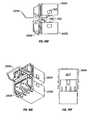
- FIGS. 22A-22Han alternative embodiment of a nose receptacle 2200 , including a pull-actuator 2200 for fiber optic modules is illustrated.
- the pull-actuator or de-latch puller 2202can be used to de-couple and remove the fiber optic module (only the nose receptacle 2200 portion is shown) by pulling the pull-actuator 2202 backwards or away from the nose receptacle 2200 .
- the nose receptacle 2200may be incorporated as part of a fiber optic module or pluggable fiber optic module as previously illustrated in other embodiments described above (i.e., 100 , 700 , etc.).
- FIG. 22Hillustrates how a fiber optic module (nose receptacle 2200 portion shown) may include the pull-actuator 2202 and a pivot-arm actuator 2204 to couple and decouple the fiber optic module to a cage assembly or module receptacle such as 1100 (only cage assembly latch portion 1102 is shown).
- the pivot-arm actuator 2204latches with the cage assembly latch 1102 to secure the fiber optic module to the cage assembly.
- FIG. 23further illustrates the pull-actuator 2202 , pivot-arm actuator 2204 and cage assembly latch 1102 .
- the pivot-arm actuator 2204includes a latch key, keeper, pin, hook, or boss 2502 (these terms are herein used interchangeably) which engages with a catch or opening 1105 in the cage assembly latch 1102 to secure the fiber optic module to the cage assembly 1100 .
- the pull-actuator 2202When the pull-actuator 2202 is pulled away from the cage assembly 1100 , the pull-actuator causes the pivot-arm actuator 2204 to pivot about its pivoting pin 2506 to cause the keeper, hook or boss 2502 to disengage from the cage latch 1102 thereby releasing the nose receptacle 2200 .
- FIGS. 24A-24Iillustrate one embodiment of the pull-actuator 2202 .
- the pull-actuator 2202may include a pull-tab 2402 , an orientation indicator 2404 , and a shaft or pull-arm 2406 coupled to the pull-tab 2402 at one end.
- the pull-tab 2402may also be a pull-button, a pull-hook, a pull-ring, a pull square, or any other equivalent mechanism with which to activate the pull-actuator 2202 .
- a first surface 2408 and a second surface 2410are coupled to the other end of the pull-arm 2406 .
- the first surface 2408includes an opening or catch 2416 to allow the pivot-arm actuator to engage the pull-actuator.
- the second surface 2410may be two tabs (FIG. 24B, 2410 A and 2410 B) which define a channel 2418 through which the pivot-arm actuator 2204 moves to engage the pull-actuator 2202 .
- the pull-actuator 2202may also include an optional orientation indicator 2404 which serves to indicate the nose receptacle which the corresponding pull-actuator releases.
- an orientation indicator 2404which serves to indicate the nose receptacle which the corresponding pull-actuator releases.
- One implementation in which the orientation indicator 2404 is usefulis where the fiber optic modules are configured in a belly-to-belly configuration.
- the first surface 2408 and the second surface 2410may define grooves 2412 which serve to slideably couple the pull-actuator 2202 to the nose receptacle 2200 .
- the nose receptacle 2200may include corresponding rails on which the grooves 2412 of the pull-actuator slide.
- the groovesmay be part of the nose receptacle 2200 with the rails being part of the pull-actuator 2202 .
- the pull-actuator 2202also comprises a catch or opening 2416 on which a keeper, hook, or boss 2504 of the pivot-arm actuator 2204 engages.
- FIGS. 25A-25Iillustrate one embodiment of a pivot-arm actuator 2204 .
- the pivot-arm actuator 2204comprises a pivoting pin 2506 , a first latch key, keeper, pin, hook, boss, or engaging triangle 2502 (these terms are herein used interchangeably) at a first end, and a second latch key, keeper, pin, hook, or boss 2504 at a second end opposite the first end.
- the first keeper or hook 2502serves to secure or couple the nose receptacle 2200 or fiber optic module to the cage assembly latch 1102 .
- the second keeper or hook 2504serves to couple the pivot-arm actuator 2204 to the pull-actuator 2202 .
- first keeper and/or second keeper on the pivot-arm actuator 2204may be a catch or opening, with a corresponding keeper on the pull-actuator 2202 and/or cage assembly 1100 instead.
- the first keeper 2502couples to an opening 1105 in the cage assembly latch 1102 .
- the second keeper 2504couples to the catch or opening 2416 in the pull-actuator 2202 .
- the second keeper 2504includes a ramped sliding surface 2508 which causes the pivot-arm actuator 2204 to rotate or pivot when the pull-actuator 2202 is pulled.
- the edge on the pull-actuator 2202 on which the ramped sliding surface 2508 pivotsmay be rounded in one embodiment.
- the pivot-arm actuator 2204is pivotally coupled to the body of the nose receptacle 2200 by means of a pivoting pin 2506 .
- the pivoting pin 2506fits through a corresponding opening in the fiber optic module or nose receptacle body 2200 .
- FIGS. 26A-26Cillustrate various cross-sectional views of a fiber optic module (nose assembly 2200 and latching mechanism 2202 and 2204 are shown) engaged or coupled to a cage assembly 1100 (cage latch portion 1102 is shown). These figures show a latching mechanism employing the pull-actuator 2202 and pivot-arm actuator 2204 as illustrated in FIGS. 24A-24I and FIGS. 25A-25I respectively.
- the engaging triangle 2502fits through a corresponding opening or catch 1105 (shown in FIG. 23) to engage, couple, or secure the fiber optic module (only the nose receptacle 2200 portion is shown) to the cage assembly 1100 (only cage latch 1102 portion is shown).
- the second keeper 2504 on the pivot-arm actuator 2204fits through the opening or catch 2416 in the pull-actuator 2202 .
- surface 2414 on the pull-actuator 2202is adjacent to surface 2510 (FIG. 25E) on the pivot-arm actuator 2204 .
- FIGS. 27A-27Cthe operation of the pull-actuator 2202 and pivot-arm actuator 2204 when disengaging and withdrawing the fiber optic module (nose receptacle 2200 ) from its cage assembly 1100 (cage latch 1102 ) is illustrated.
- the pull-tab 2402 on the pull-actuator 2202is pulled away from the fiber optic module as illustrated. This causes a rounded edge 2702 on the latching surface 2414 of the pull-actuator 2202 to move against the ramped sliding surface 2508 of the pivot-arm actuator 2204 .
- the force exerted on the ramped sliding surface 2508 by the pull-actuator 2202causes the pivot-arm actuator 2204 to rotate or pivot about its pivoting pin 2506 thereby disengaging the engaging triangle or latch 2502 from the cage latch opening 1105 .
- the fiber optic modulemay then be withdrawn or removed from the cage assembly by continuing to pull on the pull-actuator 2202 or by pulling on the nose grips 714 or the nose receptacle 2202 of the fiber optic module.
- the pull-actuator 2202 ′includes legs 2808 with end-stops 2820 .
- the end-stops 2820prevent the pull-actuator 2202 ′ from moving beyond a certain point as it is pulled to release the fiber optic module from the cage assembly 1100 .
- the pull-actuator 2202 ′may include a first surface 2810 with edges 2830 that slide through grooves in the nose receptacle 2200 ′.
- FIGS. 29A-29Iillustrate yet another alternative embodiment of the pivot-arm actuator 2204 ′.
- the pivot-arm actuator 2204 ′further includes a spring 2912 .
- the spring 2912may be formed from the same material as the pivot-arm actuator 2204 ′ or it may be a separate component coupled to the pivot-arm actuator 2204 ′.
- the spring 2912may be any kind of spring including a coil spring, leaf spring, carriage spring, compression spring, conical spring, helical spring, volute spring, spiral spring, scragged spring, and other well known types of springs.
- the pivot-arm actuator 2204 ′is pivotally coupled to the body of the nose receptacle 2200 ′ by means of a pivoting pin 2906 .
- FIGS. 30A-30Cillustrate various cross-sectional views of a fiber optic module (nose assembly 2200 ′ and latching mechanism 2202 ′ and 2204 ′ shown) engaged or coupled to a cage assembly 1100 (cage latch portion 1102 is shown). These figures show a latching mechanism employing the pull-actuator 2202 ′ illustrated in FIGS. 28A-28I and pivot-arm actuator 2204 ′ illustrated in FIGS. 29A-29I.
- the spring 2912may provide some force to maintain the pivot-arm actuator 2204 ′ in an engaged position.
- FIGS. 31A-31Cillustrate how the pull-actuator 2202 ′ and pivot-arm actuator 2204 ′ operate when disengaging and withdrawing the fiber optic module (nose receptacle 2200 ′) from its cage assembly 1100 (cage latch 1102 portion shown).
- Pulling the pull-actuator 2202 ′causes the pivot-arm actuator 2204 ′ to pivot or rotate as a result of the force exerted by the rounded edge 3104 of the pull-actuator 2202 ′ on the ramped sliding surface 2908 of the pivot-arm actuator 2204 ′. As described above, this causes the engaging triangle 2902 to disengage from the cage assembly latch 1102 thereby disengaging the fiber optic module from the cage assembly.
- the spring 2912decompresses causing the pivot-arm actuator 2204 ′ to return to its initial position.
- the movement of the pivot-arm actuator 2204 ′ to its initial positioncauses pull-actuator 2202 ′ to be retracted into the fiber optic module to its initial position. This is because the ramped sliding surface 2908 exerts a retracting force on the rounded edge 3104 as it rotates or pivots back into its initial position within the catch or opening 2816 .
- the end-stops 2820serve to stop the pull-actuator 2202 ′ from being pulled too far out as the pull-actuator is pulled.
- the nose receptacle assembly 2200 ′includes a stopping edge 3102 to stop the end-stops 2820 from moving beyond a certain point.
- the end-stops 2820or their equivalents, also permit the fiber optic module to be withdrawn from the cage assembly by continuing to pull on the pull-actuator 2202 ′.
- pull mechanisms for pull-actuatorsi.e., 2202 or 2202 ′
- pull-arm 3206 portionequivalent to 1904 in FIG. 20, 2406 in FIG. 24, or 2806 in FIG. 28
- pull-actuatori.e. 2202 or 2202 ′
- FIG. 32Ashows a pull-actuator 2202 A′ with a pivoting pull-ring 3202 A pivotally coupled to the pull-arm 3206 .
- the direction in which the pull-ring 3202 A pivotsis indicated by the arrows.
- the pull-ring 3202 Ais horizontal with the pull-actuator 2202 A′.
- a userpulls on the pivot-ring 3202 A to retract the pull-actuator 22201 A′.
- FIG. 32Bshows a pull-actuator 2202 B′ with another pivoting pull-ring 3202 B pivotally coupled to the pull-arm 3206 .
- the pull-ring 3202 Bis vertical with the pull-actuator 2202 B′.
- the arrowsindicate the direction in which the pull-ring 3202 B pivots. A user pulls on the pivoting pull-ring 3202 B to retract the pull-actuator 2202 B′.
- FIG. 32Cshows a pull-actuator 2202 C′ with a fixed pull-ring 3202 C coupled to the end of the pull-arm 3206 .
- the pull-ring 3202 Cis horizontal with the pull-actuator 2202 C′. A user pulls on the pull-ring 3202 C to retract the pull-actuator 2202 C′.
- FIG. 32Dshows a pull-actuator 2202 D′ with another fixed pull-ring 3202 D coupled to the end of the pull-arm 3206 .
- the pull-ring 3202 Dis vertical with the pull-actuator 2202 D′. A user pulls on the pull-ring 3202 D to retract the pull-actuator 2202 D′.
- FIG. 32Eshows a pull-actuator 2202 E′ with another fixed pull-ring 3202 E coupled to the end of the pull-arm 3206 .
- the pull-ring 3202 Eis at an angle to the pull-actuator 2202 E′. A user pulls on the pull-ring 3202 E to retract the pull-actuator 2202 D′.
- FIG. 32Fshows a pull-actuator 2202 F′ with pull-square 3202 F coupled to the end of the pull-arm 3206 .
- the pull-square 3202 Fis horizontal with the pull-actuator 2202 F′. A user pulls on the pull-square 3202 F to retract the pull-actuator 2202 F′.
- FIG. 32Gshows a pull-actuator 2202 G′ with a pull-hook 3202 G at the end of the pull-arm 3206 . A user pulls on the pull-hook 3202 G to retract the pull-actuator 2202 G′.
- FIG. 32Hshows a pull-actuator 2202 H′ with a pull-button 3202 H coupled to the end of the pull-arm 3206 . A user pulls on the pull-button 3202 H to retract the pull-actuator 2202 H′.
- FIG. 32Ishows a pull-actuator 2202 I′ with a pull-knob 3202 I coupled to the end of the pull-arm 3206 . A user pulls on the pull-knob 3202 I to retract the pull-actuator 2202 I′.
- FIGS. 32A-321provide some embodiments of pull-mechanisms for the pull-actuator (i.e. 2202 or 2202 ′) and that other pull-mechanisms known to those skilled in the art may also be employed.
- FIGS. 33A-33Dvarious views of a belly-to-belly mounting configuration for another embodiment of the invention is illustrated.
- the fiber optic module illustrated in FIGS. 32A-32Demploy pull-actuators 2202 and 2202 ′, or their equivalents, illustrated in FIGS. 24 and 28.
- the pull-actuators 2202 A and 2202 Bare designed such that they do no interfere with each other when the fiber optic modules and their respective nose receptacles 2200 A and 2200 B are stacked as shown.
- This belly-to-belly configuration for fiber optic modulesis described with reference to FIGS. 17A-17D above; that description applies to fiber optic modules employing the pull-actuators (i.e., 2202 and 2202 ′) described herein.
- FIGS. 34A-34Ivarious views of a subassembly of a nose receptacle 3402 including a bail latch delatching mechanism for fiber optic modules is illustrated.
- the nose receptacle 3402is portion of a mechanical subassembly of a fiber optic module but only the nose receptacle 3402 portion of the fiber optic module is shown in FIGS. 34A-34I.
- the nose receptacle 3402also referred to as a nose, is an alternate embodiment to the nose receptacle or nose 151 in the fiber optic module 100 and the nose receptacle or nose 704 in the fiber optic modules 700 , 700 ′, and 700 ′.
- the nose receptacle 3402includes a bail latch 3404 , a pivoting pin 3406 , and an actuator 3408 .
- the bail latch 3404includes a push tab, actuating tab, kick, or push mechanism 3410 for pushing on the actuator 3408 and disengaging the fiber optic module from a cage. With a fiber optic module engaged into a cage or module receptacle, the bail latch 3404 can be used to disengage and withdrawal the fiber optic module from the cage or receptacle, such as cage or receptacle 1100 illustrated in FIG. 11 .
- bail latch 3404serves as the mechanical device to contact the actuator 3408 and push it to it's forward position disengaging the locking tab or latch 1102 on the cage or receptacle 1100 from holding onto the locking triangle or boss 1002 of the nose or nose receptacle 3402 .
- the bail latch 3404is first moved from an engaged position to a disengaged position.
- the engaged positionis a vertical position while the disengaged position is in a horizontal position.
- other embodiments of the bail latch and the actuatormay provide differing engaged and disengaged positions with respect to the nose receptacle 3402 and the fiber optic module of which it is a part thereof.
- the fiber optic moduleis withdrawn by pulling out or backward on the bail latch 3404 of the nose receptacle 3402 .
- the bail latch 3404provides sufficient grip and accesses the actuator 3408 for the de-latching for the withdrawing process of the fiber optic module from a cage or receptacle.
- the nose receptacle 3402is a part of an SFP fiber optic module for engaging an SFP cage.
- FIGS. 35A-35Ivarious views of a first embodiment of the bail latch 3404 including the pivoting pin 3406 for one embodiment of the invention are illustrated.
- the bail latch 3404includes a pair of pivot points or side tabs 3502 ; the push tab, kick, or push mechanism 3410 ; and a pulling arm or pull-handle 3504 coupled to a center member 3505 as shown and illustrated in FIGS. 35A-35I.
- these components of bail latch 3404can hug along the front face and side face of the nose receptacle 3402 and form a G-like shape when viewed from the side.
- the pivot points or side tabs 3502can each include a hole or opening 3506 to accept the pivot pin 3406 .
- the center axis of the two holes or openings 3506 in the side tabs 3502is the axis of pivoting of the bail latch 3404 and hence the pivoting pin 3406 is located there at.
- the bail latch 3404is rotatably coupled to the nose receptacle 3402 by the pivoting pin 3406 .
- the pulling arm or pull-handle 3504includes an opening 3412 which allows a finger to be inserted to pull out the fiber optic module when in an disengaged position.
- the opening 3412also allows fiber optic plugs and optical fibers to be inserted into the nose receptacle 3402 when its in an engaged position.
- the pulling arm or pull handle 3504may include a grip 3414 to ease grabbing the bail latch 3404 from an engaged position into a disengaged position.
- the bail latch 3404can be formed out of metal, plastic (including a thermoplastic), thermosett, epoxy, or other solid materials.
- the pivoting pin 3406which can also be referred to as a rod, is a long thin rod or cylinder of metal, thermoplastic, thermosett, epoxy or other solid material having an axis about which the bail latch can be rotated.
- the pivoting pin 3406holds the bail latch rotatably coupled together to the nose receptacle 3402 .
- the pivoting pinserves as a pivoting device for bail latch 3404 .
- the pivoting pin 3406holds the bail latch coupled to the nose receptacle 3402 as shown in FIG. 3 .
- the nose receptacle 3402includes a pair of openings or holes in each side or alternatively a long opening or hole through its body if solid at that point to accept the pivoting pin 3406 . Referring momentarily to FIGS. 38D and 38E, an opening 3801 in the left side of the nose receptacle 3402 is illustrated with the pivoting pin 3406 inserted therein.
- the actuator 3408is somewhat similar to the structure and functionality of the actuator 706 previously described with reference to FIGS. 7A-14B and the fiber optic modules described therein.
- the actuator 3408is a conventional actuator in conformance with the MSA Standard for SFP fiber optic modules.
- the actuator 3408may be tailored to appropriately couple with the bail latch 3404 .
- the actuator 3408functions to disengage the fiber optic module from the cage 1100 when pushed by the push tab 2410 of the bail latch 3404 .
- the actuator 3408includes a butting surface 3601 ; a pair of sliding guide slots or grooves 721 on each side; and one or more ramps, wedges or lifters (a pair of which are illustrated) 1308 .
- the butting surface 3601is part of the back side of the actuator 3408 while the ramps, wedges, or lifters 1308 are part of the front side of the actuator 3408 .
- the slot or grooves 721 on each side of the actuator 3408have an opening at one end and a closure at an opposite end.
- the slot or grooves 721slideably engage tangs 741 in the nose receptacle 3402 . While illustrated in FIGS.
- the tangs 741 of the nose receptacle 3402are better illustrated in the exploded view of the nose receptacle 704 of FIG. 7 B.
- the butting surface 3601 of the actuator 3408makes contact with the push tab 3410 of the bail latch 3404 when the fiber optic module is being disengaged.
- the one or more ramps, wedges, or lifters 1308make contact with the latch 1102 of the cage 1100 to disengage the fiber optic module as is described below and in FIGS. 12, 13 A- 13 B, and 14 A- 14 B.
- the actuator 3408may be formed out of metal, thermoplastic, thermosett, epoxy or other solid material.
- FIGS. 37A-37E and FIGS. 38A-38Evarious cross-sectional views of an integrated nose assembly and latching mechanism of FIGS. 34A-34I in the engaged position and the disengaged position respectively for one embodiment of the invention are illustrated.
- the bail latch 3404in an upright, closed, or engaged position. That is, the fiber optic module can be securely engaged with the cage with the bail latch 3404 in this position. The fiber optic module can be pushed into the cage 1100 with the bail latch 3404 in its upright, closed, or engaged position. With the bail latch 3404 in its upright, closed, or engaged position, the actuator 3408 and its ramps, wedges, or lifters 1308 can be in a backward, locking or engaging position well away from the boss or locking triangle 1002 in the nose receptacle 3402 . This allows the boss or locking triangle 1002 in the nose receptacle 3402 to mate or engage into the opening or catch 1105 in the latch 1102 .
- the bail latch 3404can be pulled on as shown by the force arrow 3701 to cause it to first rotate around the axis of the pivoting pin 3406 as illustrated by the arrow 3702 . As the bail latch 3404 rotates from its an upright, closed, or engaged position, a user can insert the same finger into the opening 3412 of the pull handle 3414 in order to continue pulling outward on the fiber optic module.
- the bail latch 3404is in a horizontal, open, or disengaged position.
- the bent portion of handle 3414allows a user to keep the finger in the opening 3412 and continue pulling outward on the fiber optic module even when its in the horizontal, open, or disengaged position.
- the bail latchcan first rotate around the axis along the bottom portion of the nose receptacle 3402 .
- the push tab 3410 of the bail latch 3404extends gradually forward. The extension of push tab 3410 comes in contact with the butting surface 3601 of the actuator 3408 to slide it forward towards the latch 1102 of the cage 1100 .
- the cagemay include a boss or locking triangle which is pushed out of a hole or opening in the nose receptacle to disengage the fiber optic module from the cage.
- a continuous pulling actionas illustrated by the pull force 3802 on the bail latch 3404 , can withdraw the fiber optic module fully out of the cage. In this manner a single continuous pulling action on the bail latch 3404 can disengage and withdraw the fiber optic module out of the cage.
- bail latch 3404With the bail latch 3404 in its horizontal, open, or disengaged position, it can be easily be returned to its upright, closed, or engaged position within or without the cage 1100 by using an opposite force.
- the bail latch 3404could be spring loaded by including a spring to return it to its upright, closed, or engaged position on its own.
- the action of the actuator 3408is similar to that of the actuator 706 and the one or more ramps, wedges, or lifters 1308 as described with respect to FIGS. 12, 13 A- 13 B, and 14 A- 14 B.
- FIGS. 39A-39Hillustrate various views of alternate embodiments of the bail latch 3404 as well as other delatching mechanisms that can function similar to the bail latch 3404 with a push tab 3410 .
- FIG. 39Aillustrates a bail latch 3404 A′in which the pivot pin 3406 is replaced with two smaller pins 3406 A′ that do not extend across the width of the bail latch 3404 A′.
- the bail latch 3404 A′includes the actuating tab 3410 .
- FIG. 39Billustrates a latch 3404 B′ with a partial pull arm 3504 B′ coupled to a lever 3901 instead of a complete bail latch pull arm.
- the bail latch 3404 B′may include a pair of pivot pins 3406 B′ instead of the pivot pin 3406 .
- FIG. 39Cillustrates a latch 3404 C′ with a partial pull arm (as in FIG. 39B) with a long pivot pin 3406 C′ coupled to the latch 3404 C′ at only one side.
- FIG. 39Dillustrates a bail latch 3404 D′ with an enclosed pull arm 3504 D′ with no angles.
- the latch 3404 D′further includes another embodiment of the actuating tab 3410 D′ where the tab has an oval or circular tip to slide on the butting surface 3601 and release the fiber optic module.
- the actuating tab 3410 D′is narrower than the first actuating tab 3410 .
- FIG. 39Eillustrates a bail latch 3404 E′ with a semi-circular pull arm 3504 E′.
- FIG. 39Fillustrates a latch 3404 F, with just a lever arm 3504 F′ to release the fiber optic module from the cage assembly.
- FIG. 39Gillustrates a latch 3404 G′ with pivoting conical retainers 3406 G′ instead of pivot pins to couple the latch 3404 G′ to the fiber optic module.
- FIG. 39Hillustrates a bail latch 3404 H′ with holes 3902 rather than pins.
- the fiber optic module or nose receptacleprovides pins or protrusions which fit through the holes 3902 to pivotally couple the latch 3404 H′ to the fiber optic module.
- FIGS. 40A-40Ivarious views of how the bail-latch delatching mechanism would function in a belly-to-belly mounting configuration for another embodiment of the invention.
- a first fiber optic module and a second fiber optic modulecan be engaged into cages in a belly to belly configuration in which case a first nose receptacle 3402 A would be adjacent and parallel to a second nose receptacle 3402 B as illustrated in FIGS. 40A-40I.
- the bail latch de-latching mechanismcan be designed to functional at extreme close gap condition when using a belly to belly mounting configuration as illustrated if FIGS. 40A-40I.
- the distance between top and bottom cages or receptaclescan be less than 1.0 millimeter and allow the bail latches 3404 A and 3404 B of the first and second nose receptacles 3402 A and 3402 B respectively to properly function into an open or closed position.
- FIGS. 40A-40Iillustrate only the first bail latch 3404 A being in an open or engaged position
- either the first or second bail latches 3404 A or 3404 Bcan be opened or in a disengaged position.
- both the top or bottom bail latches 3404 A and 3404 Bcan be opened or disengaged for some reason if desired.
- This belly-to-belly configuration for fiber optic modulesis described further with reference to FIGS. 17A-17D above; that description applies to fiber optic modules employing the bail latch delatching mechanism of the nose receptacle 3402 described herein.
- the inventionhas a number of advantages over the prior art that will be recognized by those of ordinary skill in the art after thoroughly reading this disclosure.
Landscapes
- Physics & Mathematics (AREA)
- General Physics & Mathematics (AREA)
- Optics & Photonics (AREA)
- Optical Couplings Of Light Guides (AREA)
Abstract
Description
Claims (42)
Priority Applications (3)
| Application Number | Priority Date | Filing Date | Title |
|---|---|---|---|
| US09/939,413US6796715B2 (en) | 2001-04-14 | 2001-08-23 | Fiber optic modules with pull-action de-latching mechanisms |
| US10/405,578US6883971B2 (en) | 2001-04-14 | 2003-04-01 | Pull-action de-latching mechanisms for fiber optic modules |
| US10/797,869US6974265B2 (en) | 2001-04-14 | 2004-03-09 | Fiber optic modules with de-latching mechanisms having a pull-action |
Applications Claiming Priority (3)
| Application Number | Priority Date | Filing Date | Title |
|---|---|---|---|
| US28384301P | 2001-04-14 | 2001-04-14 | |
| US09/896,695US6863448B2 (en) | 2001-04-14 | 2001-06-28 | Method and apparatus for push button release fiber optic modules |
| US09/939,413US6796715B2 (en) | 2001-04-14 | 2001-08-23 | Fiber optic modules with pull-action de-latching mechanisms |
Related Parent Applications (1)
| Application Number | Title | Priority Date | Filing Date |
|---|---|---|---|
| US09/896,695Continuation-In-PartUS6863448B2 (en) | 2001-04-14 | 2001-06-28 | Method and apparatus for push button release fiber optic modules |
Related Child Applications (2)
| Application Number | Title | Priority Date | Filing Date |
|---|---|---|---|
| US10/405,578DivisionUS6883971B2 (en) | 2001-04-14 | 2003-04-01 | Pull-action de-latching mechanisms for fiber optic modules |
| US10/797,869ContinuationUS6974265B2 (en) | 2001-04-14 | 2004-03-09 | Fiber optic modules with de-latching mechanisms having a pull-action |
Publications (2)
| Publication Number | Publication Date |
|---|---|
| US20020150344A1 US20020150344A1 (en) | 2002-10-17 |
| US6796715B2true US6796715B2 (en) | 2004-09-28 |
Family
ID=46278044
Family Applications (3)
| Application Number | Title | Priority Date | Filing Date |
|---|---|---|---|
| US09/939,413Expired - LifetimeUS6796715B2 (en) | 2001-04-14 | 2001-08-23 | Fiber optic modules with pull-action de-latching mechanisms |
| US10/405,578Expired - LifetimeUS6883971B2 (en) | 2001-04-14 | 2003-04-01 | Pull-action de-latching mechanisms for fiber optic modules |
| US10/797,869Expired - LifetimeUS6974265B2 (en) | 2001-04-14 | 2004-03-09 | Fiber optic modules with de-latching mechanisms having a pull-action |
Family Applications After (2)
| Application Number | Title | Priority Date | Filing Date |
|---|---|---|---|
| US10/405,578Expired - LifetimeUS6883971B2 (en) | 2001-04-14 | 2003-04-01 | Pull-action de-latching mechanisms for fiber optic modules |
| US10/797,869Expired - LifetimeUS6974265B2 (en) | 2001-04-14 | 2004-03-09 | Fiber optic modules with de-latching mechanisms having a pull-action |
Country Status (1)
| Country | Link |
|---|---|
| US (3) | US6796715B2 (en) |
Cited By (27)
| Publication number | Priority date | Publication date | Assignee | Title |
|---|---|---|---|---|
| US20030108300A1 (en)* | 2001-12-06 | 2003-06-12 | Walker Harold Y. | Method and system for releasing a pluggable module |
| US20040218288A1 (en)* | 2003-05-02 | 2004-11-04 | International Business Machines Corporation | Optical communication assembly |
| US6966703B1 (en)* | 2003-02-03 | 2005-11-22 | Bookham Technology Plc | Self eject latch mechanism for an optical transceiver module |
| US6974265B2 (en)* | 2001-04-14 | 2005-12-13 | Jds Uniphase Corporation | Fiber optic modules with de-latching mechanisms having a pull-action |
| US20070036489A1 (en)* | 2005-08-15 | 2007-02-15 | Barbara Grzegorzewska | Industrial interconnect system incorporating transceiver module cage |
| US7300215B2 (en) | 2004-06-04 | 2007-11-27 | Industrial Technology Research Institute | Light transceiver module |
| US7327564B2 (en) | 2004-07-02 | 2008-02-05 | Seagate Technology Llc | Engagement system for a module in an electronics cabinet |
| US20080247762A1 (en)* | 2007-04-03 | 2008-10-09 | Satoshi Yoshikawa | Pluggable optical transceiver |
| US20090176401A1 (en)* | 2008-01-07 | 2009-07-09 | Applied Optoelectronics, Inc. | Pluggable form factor release mechanism |
| US20110217009A1 (en)* | 2010-03-04 | 2011-09-08 | Fujitsu Network Communications, Inc. | System for Mounting Optical Modules in an Optical Network |
| US20140037259A1 (en)* | 2012-08-01 | 2014-02-06 | Leviton Manufacturing Co., Inc. | Low profile copper and fiber optic cassettes |
| WO2014186338A1 (en)* | 2013-05-14 | 2014-11-20 | Applied Optoelectronics, Inc. | Compact multi-channel optical transceiver module |
| US20140341578A1 (en)* | 2013-05-14 | 2014-11-20 | Applied Optoelectronics, Inc. | Aligning and directly optically coupling photodetectors to optical demultiplexer outputs in a multichannel receiver optical subassembly |
| US9225428B1 (en) | 2014-08-21 | 2015-12-29 | Applied Optoelectronics, Inc. | Method and system for alignment of photodetector array to optical demultiplexer outputs |
| WO2016137486A1 (en)* | 2015-02-27 | 2016-09-01 | Hewlett Packard Enterprise Development Lp | Features to conjoin one-lane cable assemblies |
| US9690064B2 (en) | 2015-11-10 | 2017-06-27 | Leviton Manufacturing Co., Ltd. | Multi-gang cassette system |
| US9847434B2 (en) | 2015-03-23 | 2017-12-19 | Applied Optoelectronics, Inc. | Multichannel receiver optical subassembly with improved sensitivity |
| US10185109B2 (en)* | 2016-12-29 | 2019-01-22 | Mellanox Technologies, Ltd. | Modular system for datacenter switch systems and routers |
| US10295773B2 (en) | 2017-03-29 | 2019-05-21 | Leviton Manufacturing Co., Inc. | Segregated fiber in a splice cassette |
| US11811163B2 (en) | 2021-02-26 | 2023-11-07 | Leviton Manufacturing Co., Inc. | Mutoa and quad floating connector |
| US12158623B2 (en) | 2016-12-05 | 2024-12-03 | Senko Advanced Components, Inc. | Optical fiber connector |
| US12222559B2 (en) | 2016-01-15 | 2025-02-11 | Senko Advanced Components, Inc. | Narrow width adapters and connectors with pull tab release |
| US12228774B2 (en) | 2017-07-14 | 2025-02-18 | Senko Advanced Components, Inc. | Ultra-small form factor optical connector and adapter |
| US12235493B2 (en) | 2017-07-14 | 2025-02-25 | Senko Advanced Components, Inc. | Small form factor fiber optic connector with multi-purpose boot |
| US12248191B2 (en) | 2017-07-14 | 2025-03-11 | Senko Advanced Components, Inc. | Fiber optical connectors |
| US12259585B2 (en) | 2015-03-03 | 2025-03-25 | Senko Advanced Components, Inc. | Optical fiber connector with changeable polarity |
| US12399329B2 (en) | 2016-06-28 | 2025-08-26 | Senko Advanced Components, Inc. | Adapter system for multi-fiber mechanical transfer type ferrule |
Families Citing this family (68)
| Publication number | Priority date | Publication date | Assignee | Title |
|---|---|---|---|---|
| US6533470B2 (en)* | 2001-03-16 | 2003-03-18 | Infineon Technologies North America Corp. | Single-piece cage for pluggable fiber optic transceiver |
| US6916196B2 (en)* | 2003-03-22 | 2005-07-12 | Tyco Electronics Corporation | Push button de-latch mechanism for pluggable electronic module |
| JP4321111B2 (en)* | 2003-05-16 | 2009-08-26 | 日本電気株式会社 | OPTICAL MODULE, METHOD FOR RELEASE LOCK STATUS OF OPTICAL MODULE AND CAGE |
| US7201520B2 (en)* | 2003-05-30 | 2007-04-10 | Sumitomo Electric Industries, Ltd. | Optical module having a simple mechanism for releasing from a cage |
| JP4117476B2 (en)* | 2003-05-30 | 2008-07-16 | 日本電気株式会社 | Optical module, optical module / cage assembly, optical module / cage locking method and unlocking method |
| US8923704B2 (en)* | 2003-08-29 | 2014-12-30 | Finisar Corporation | Computer system with modular optical devices |
| US6962445B2 (en) | 2003-09-08 | 2005-11-08 | Adc Telecommunications, Inc. | Ruggedized fiber optic connection |
| KR20050051232A (en)* | 2003-11-27 | 2005-06-01 | 주식회사 오이솔루션 | Latch type optical module |
| JP4458239B2 (en)* | 2003-12-26 | 2010-04-28 | 日本電気株式会社 | Unlocking mechanism, optical module, and unlocking method |
| US7212410B2 (en)* | 2004-01-16 | 2007-05-01 | Finisar Corporation | Actuator for small form-factor pluggable transceiver |
| US6997622B2 (en)* | 2004-01-16 | 2006-02-14 | Infineon Technologies Ag | Mode indicator for transceiver module |
| US7625135B2 (en)* | 2004-01-16 | 2009-12-01 | Finisar Corporation | Dual configuration transceiver housing |
| JP4133869B2 (en)* | 2004-03-01 | 2008-08-13 | 富士通株式会社 | Data link module structure |
| US7108523B2 (en)* | 2004-04-07 | 2006-09-19 | Finisar Corporation | Pluggable transceiver with cover resilient member |
| JP2005316475A (en)* | 2004-04-29 | 2005-11-10 | Sumitomo Electric Ind Ltd | Optical transceiver |
| US7447440B2 (en)* | 2004-05-17 | 2008-11-04 | Cisco Technology, Inc. | Multiple channel optical transceiver modules |
| US20060002666A1 (en)* | 2004-06-30 | 2006-01-05 | Ice Donald A | Shaped lead assembly for optoelectronic devices |
| US7093985B2 (en)* | 2004-07-12 | 2006-08-22 | Protokraft, Llc | Wall mount fiber optic connector and associated method for forming the same |
| US20060110164A1 (en)* | 2004-11-19 | 2006-05-25 | Kirk Cook | Multiple PCBA transceiver |
| US7563035B2 (en)* | 2005-04-29 | 2009-07-21 | Finisar Corporation | Connector for box optical subassembly |
| US7488120B2 (en)* | 2005-12-29 | 2009-02-10 | Intel Corporation | Fiber optic module and optical subassembly with reduced electromagnetic interference |
| US7234880B1 (en) | 2006-01-09 | 2007-06-26 | Acterna L.L.C. | Internal pluggable optical module |
| US9250399B2 (en)* | 2006-08-31 | 2016-02-02 | Optogig, Inc. | High density active modular optoelectronic device for use with push-release mechanism and method for using same |
| DE102006046777B4 (en)* | 2006-09-29 | 2010-04-29 | Continental Automotive Gmbh | Plug-in system for coupling at least one optical fiber |
| US7513698B2 (en)* | 2006-11-09 | 2009-04-07 | Zarlink Semiconductor Ab | Releasable optical connector |
| US7572065B2 (en) | 2007-01-24 | 2009-08-11 | Adc Telecommunications, Inc. | Hardened fiber optic connector |
| US7591595B2 (en) | 2007-01-24 | 2009-09-22 | Adc Telelcommunications, Inc. | Hardened fiber optic adapter |
| US7835410B2 (en)* | 2007-02-07 | 2010-11-16 | Finisar Corporation | Opto-isolator including a vertical cavity surface emitting laser |
| US7374347B1 (en)* | 2007-05-07 | 2008-05-20 | Sumitomo Electric Industries, Ltd. | Optical pluggable transceiver with securable latching mechanism |
| US7625240B2 (en)* | 2007-10-26 | 2009-12-01 | Cisco Technology, Inc. | Receptacle connector |
| US7762726B2 (en) | 2007-12-11 | 2010-07-27 | Adc Telecommunications, Inc. | Hardened fiber optic connection system |
| JP2009210669A (en)* | 2008-03-03 | 2009-09-17 | Furukawa Electric Co Ltd:The | Connector unit |
| CN201207501Y (en)* | 2008-04-30 | 2009-03-11 | 富士康(昆山)电脑接插件有限公司 | Connector module |
| US7465103B1 (en)* | 2008-06-25 | 2008-12-16 | Comosss Electronic Co., Ltd. | Plastic fiber cable coupling structure |
| US20100080517A1 (en)* | 2008-09-29 | 2010-04-01 | Cline Timothy S | Fiber optic connector assembly employing fiber movement support and method of assembly |
| CH700063A2 (en)* | 2008-12-05 | 2010-06-15 | Huber+Suhner Ag | Test adapter for computer chips. |
| TW201044719A (en)* | 2009-06-01 | 2010-12-16 | Hon Hai Prec Ind Co Ltd | Connector |
| US8050057B2 (en)* | 2009-06-03 | 2011-11-01 | System General Corporation | Mounting structure for an electronic element |
| CN102346279B (en)* | 2010-07-30 | 2015-03-11 | 株式会社藤仓 | Optical connector and connector connection system |
| US8251721B2 (en)* | 2010-08-23 | 2012-08-28 | Canare Electric Co., Ltd | Active connector |
| US20120141073A1 (en)* | 2010-12-01 | 2012-06-07 | Reflex Photonics Inc. | Optical sub-assembly with strain relief feature |
| US8297856B2 (en)* | 2010-12-13 | 2012-10-30 | Sae Magnetics (H.K.) Ltd. | Electro-optical module and multi-functional latch member therefor |
| US8388366B2 (en)* | 2011-05-26 | 2013-03-05 | All Best Electronics Co., Ltd. | Pull-out structure for connector |
| WO2013052070A1 (en)* | 2011-10-05 | 2013-04-11 | Senko Advanced Components, Inc. | Latching connector with remote release |
| US8588572B2 (en)* | 2011-11-28 | 2013-11-19 | Avago Technologies General Ip (Singapore) Pte. Ltd. | Electromagnetic interference (EMI) waveguide device for use in a parallel optical communications module, and a method |
| EP2618561A3 (en)* | 2012-01-20 | 2014-01-22 | Embrionix Design Inc. | Small form-factor pluggable unit having a plurality of insertable cages |
| CA2803501A1 (en)* | 2012-01-20 | 2013-07-20 | Embrionix Design Inc. | Small form-factor pluggable unit having a plurality of insertable cages |
| AU2013267607B2 (en) | 2012-05-30 | 2014-12-18 | Schweitzer Engineering Laboratories, Inc. | Thermal management of a communication transceiver in an electrical communication device |
| CN203037897U (en)* | 2012-12-13 | 2013-07-03 | 武汉电信器件有限公司 | Socket SFP photoelectric module |
| WO2014206976A1 (en) | 2013-06-27 | 2014-12-31 | Tyco Electronics Raychem Bvba | Fiber optic cable anchoring device for use with fiber optic connectors and methods of using the same |
| CN104749716A (en)* | 2013-12-31 | 2015-07-01 | 台达电子工业股份有限公司 | Optical fiber connector |
| US9411111B2 (en)* | 2014-12-09 | 2016-08-09 | Sae Magnetics (H.K.) Ltd. | Pluggable optical connector, lock and release mechanism therefor |
| US9810422B2 (en)* | 2016-02-04 | 2017-11-07 | Dell Products L.P. | Floating apparatus for fixing membrane cable for fan module lighting |
| US10659168B2 (en) | 2016-08-23 | 2020-05-19 | Schweitzer Engineering Laboratories, Inc. | Low-power fiber optic transceiver |
| US9851517B1 (en)* | 2017-02-22 | 2017-12-26 | Sae Magnetics (H.K.) Ltd. | Micro optical engine assembly |
| US10514515B2 (en)* | 2017-03-30 | 2019-12-24 | Applied Optoelectronics, Inc. | Techniques for shielding within an optical transceiver housing to mitigate electromagnetic interference between optical subassemblies disposed within the same |
| CN109991704A (en)* | 2018-01-02 | 2019-07-09 | 台达电子工业股份有限公司 | Optical transceiver module |
| US11194101B2 (en)* | 2018-09-11 | 2021-12-07 | Senko Advanced Components, Inc. | LC one piece front loaded ferrule with unitary retainer and ferrule holder |
| US11181696B2 (en)* | 2019-02-22 | 2021-11-23 | Senko Advanced Components, Inc. | Adapter assembly having a return spring with a push-pull tab |
| WO2020180806A1 (en) | 2019-03-02 | 2020-09-10 | Senko Advanced Components, Inc | Fiber management enclosure for a fiber optic connector assembly and method of use |
| CN113296198A (en)* | 2020-02-21 | 2021-08-24 | 佑胜光电股份有限公司 | Optical transmission assembly, optical transceiver module and optical fiber cable module |
| US11086081B2 (en) | 2019-03-21 | 2021-08-10 | Schweitzer Engineering Laboratories, Inc. | Conductive cooling for small form-factor pluggable (SFP) fiber optic transceivers |
| CN110082870B (en)* | 2019-05-31 | 2024-06-25 | 浙江舜宇光学有限公司 | TO-CAN pipe cap |
| US11411650B2 (en)* | 2020-01-24 | 2022-08-09 | Applied Optoelectronics, Inc. | Component bridge for increasing mounting surface area on feedthrough device and an optical subassembly implementing same |
| TWI755686B (en)* | 2020-02-20 | 2022-02-21 | 立佳興業股份有限公司 | Optical receptacle and module and optical connector module using the same |
| CN216792511U (en)* | 2021-05-08 | 2022-06-21 | 苏州旭创科技有限公司 | Optical module |
| US12334977B2 (en) | 2022-12-19 | 2025-06-17 | Schweitzer Engineering Laboratories, Inc. | Fiber optic signal monitoring |
| US20240272390A1 (en)* | 2023-02-14 | 2024-08-15 | Ii-Vi Delaware, Inc. | Dual duplex belly-to-belly little connector (bblc) based optical connectors |
Citations (270)
| Publication number | Priority date | Publication date | Assignee | Title |
|---|---|---|---|---|
| US1835251A (en) | 1926-09-23 | 1931-12-08 | Wetstein Mentor | Separable plug |
| US1899360A (en) | 1931-06-02 | 1933-02-28 | Kenneth B Roudebush | Electric plug |
| US2384267A (en) | 1942-04-25 | 1945-09-04 | Johan M Andersen | Electrical connector |
| US2714195A (en) | 1951-09-19 | 1955-07-26 | John W Beatty | Quick connect-disconnect electrical connectors |
| US2760174A (en) | 1954-08-13 | 1956-08-21 | Burtt | Locking mechanism for electrical connectors |
| US2767008A (en) | 1952-04-05 | 1956-10-16 | Joseph H Oswald | Cam fastener for panel closures |
| US2872139A (en) | 1953-10-21 | 1959-02-03 | Jr William A Bedford | Fastening device |
| US2881404A (en) | 1952-06-28 | 1959-04-07 | Lawrence J Kamm | Multiple electrical connector with yieldable contacts |
| US2899669A (en) | 1959-08-11 | Electrical connector | ||
| US3017232A (en) | 1960-12-27 | 1962-01-16 | Applied Dev Corp | Printed circuit board file |
| US3035243A (en) | 1961-04-03 | 1962-05-15 | Gen Electric | Lever mechanism for multiple electrical connectors |
| US3311863A (en) | 1964-05-25 | 1967-03-28 | Scanbe Mfg Corp | Printed circuit board hardware |
| US3398390A (en) | 1966-07-18 | 1968-08-20 | Gen Electric | Spring lock electrical connector |
| US3408614A (en) | 1966-01-03 | 1968-10-29 | Hirose Electric Co Ltd | Electric connecting device |
| US3451034A (en) | 1966-12-19 | 1969-06-17 | Scanbe Mfg Corp | Printed circuit board ejection and locking mechanism |
| US3476258A (en) | 1967-05-18 | 1969-11-04 | Friden Inc | Board insertion and extraction system |
| US3495206A (en) | 1967-04-29 | 1970-02-10 | Bolkow Gmbh | Disengageable electric connector |
| US3518612A (en) | 1966-08-06 | 1970-06-30 | Ibm | Connector assembly |
| US3566190A (en) | 1968-12-23 | 1971-02-23 | Raven Ind Inc | Industrial control system with means for releasably securing a plurality of electronic modules |
| US3566336A (en) | 1968-08-30 | 1971-02-23 | Itt | Connector assembly |
| US3576515A (en) | 1968-08-27 | 1971-04-27 | Amp Inc | Printed circuit edge connector |
| US3594698A (en) | 1969-06-30 | 1971-07-20 | Itt | Low insertion force connector assembly |
| US3668605A (en) | 1970-08-10 | 1972-06-06 | North Electric Co | Multi-point program plug and receptacle connector arrangement having positive alignment prior to positive mating |
| US3736471A (en) | 1970-11-18 | 1973-05-29 | I Honeywell Bull Soc | Assemblage element for functional unit with card connector means |
| US3767974A (en) | 1972-01-03 | 1973-10-23 | Cogar Corp | Insertion and extraction lever for printed circuit cards |
| US3784954A (en) | 1971-05-06 | 1974-01-08 | Inventio Ag | Apparatus for plug connection of printed circuit boards |
| US3798507A (en) | 1972-11-02 | 1974-03-19 | Augat Inc | Rack assembly for electrical terminal panels |
| US3803409A (en) | 1972-07-14 | 1974-04-09 | Us Army | Coaxial diode mount for use with fiber optic light guide |
| US3806225A (en) | 1972-11-28 | 1974-04-23 | G Codrino | Terminal fastener for light-guide cables |
| US3809908A (en) | 1973-06-29 | 1974-05-07 | Itt | Electro-optical transmission line |
| US3915538A (en) | 1974-10-17 | 1975-10-28 | Molex Inc | Zero insertion force connector assembly |
| US3950059A (en) | 1975-06-27 | 1976-04-13 | International Telephone & Telegraph Corporation | Zero force electrical connector |
| US3952232A (en) | 1974-06-03 | 1976-04-20 | Richco Plastic Company | Circuit board ejector |
| US3951514A (en) | 1974-12-23 | 1976-04-20 | International Telephone And Telegraph Corporation | Connector member |
| US4045109A (en) | 1976-03-08 | 1977-08-30 | International Telephone And Telegraph Corporation | Electronic packaging assembly |
| US4064551A (en) | 1976-11-29 | 1977-12-20 | Northern Telecom Limited | Apparatus for insertion and withdrawal of printed circuit boards into and from mounting frames |
| US4070081A (en) | 1975-10-13 | 1978-01-24 | Yamaichi Electric Mfg., Co., Ltd. | Coupling mechanism for male and female connectors |
| US4083619A (en) | 1977-06-20 | 1978-04-11 | Automation Industries, Inc. | Electrical connector |
| US4083616A (en) | 1977-02-07 | 1978-04-11 | Stromberg-Carlson Corporation | Printed wiring board levered inject-eject cam |
| US4084882A (en) | 1976-08-30 | 1978-04-18 | International Telephone And Telegraph Corporation | Connector member |
| US4140367A (en) | 1976-10-08 | 1979-02-20 | Bunker Ramo Corporation | Multiple channel connector for fiber optic cables |
| US4149072A (en) | 1977-08-05 | 1979-04-10 | Minnesota Mining And Manufacturing Company | System for flat ribbon optical fiber data communications link |
| US4152038A (en) | 1977-03-23 | 1979-05-01 | Bunker Ramo Corporation | Electrical connector |
| US4167303A (en) | 1977-07-28 | 1979-09-11 | Amp Incorporated | Light transmitting fiber cable connector |
| US4197572A (en) | 1977-06-01 | 1980-04-08 | Itw Fastex Italia, S.P.A. | Device for engagement and disengagement of printed circuit cards |
| US4217030A (en) | 1978-07-18 | 1980-08-12 | Bell Telephone Laboratories, Incorporated | Fiberoptic-electronic connector assembly |
| US4226491A (en) | 1978-04-28 | 1980-10-07 | Fujitsu Limited | Electronic device having a printed circuit board unit therein |
| US4233646A (en) | 1979-06-29 | 1980-11-11 | Northern Telecom Limited | Latching lever for printed circuit boards |
| US4243283A (en) | 1979-09-17 | 1981-01-06 | Rca Corporation | Circuit board guide and ground connector |
| US4260210A (en) | 1979-06-29 | 1981-04-07 | International Business Machines Corporation | Pluggable module actuation and retention device |
| US4268114A (en) | 1978-09-01 | 1981-05-19 | Thomson-Csf | Optical connector for printed circuit card |
| US4273413A (en) | 1979-02-26 | 1981-06-16 | Amp Incorporated | Photoelectric element/optical cable connector |
| US4295181A (en) | 1979-01-15 | 1981-10-13 | Texas Instruments Incorporated | Module for an integrated circuit system |
| US4301494A (en) | 1979-09-28 | 1981-11-17 | Wescom, Inc. | Printed circuit board faceplate assembly |
| US4313150A (en) | 1979-09-24 | 1982-01-26 | Northern Telecom Limited | Latching lever for printed circuit boards |
| US4377318A (en) | 1978-02-06 | 1983-03-22 | Everett/Charles, Inc. | Low insertion force electrical interface assembly and actuable interface assembly therefor |
| US4384368A (en) | 1980-05-22 | 1983-05-17 | Siemens Aktiengesellschaft | Insulated insert with high electric strength |
| US4387956A (en) | 1981-06-09 | 1983-06-14 | Rockwell International Corporation | Fiber optic interlock |
| US4398073A (en) | 1977-04-29 | 1983-08-09 | Itt Industries, Inc. | Fastening device for a switch |
| US4406514A (en) | 1980-03-26 | 1983-09-27 | Harris Corporation | Single fiber connector for pluggable card or module optical interconnections |
| US4410222A (en) | 1980-07-05 | 1983-10-18 | Molex Incorporated | Electrical connector for a ribbon cable |
| US4427879A (en) | 1975-04-18 | 1984-01-24 | Allied Corporation | Optoelectronic connector assembly |
| US4432604A (en) | 1982-04-28 | 1984-02-21 | Bell Telephone Laboratories, Incorporated | Self-adjusting fiberoptic connector assembly |
| US4439006A (en) | 1981-05-18 | 1984-03-27 | Motorola, Inc. | Low cost electro-optical connector |
| US4445740A (en) | 1982-04-26 | 1984-05-01 | Rockwell International Corporation | Circuit board assembly |
| US4448467A (en) | 1982-09-02 | 1984-05-15 | Amp Incorporated | Connector assembly having compact keying and latching system |
| US4449784A (en) | 1981-06-22 | 1984-05-22 | Trw Inc. | Hybrid optical/electrical connector |
| US4460230A (en) | 1979-02-23 | 1984-07-17 | Trw Inc. | Connector hood constructions |
| US4470660A (en) | 1981-08-28 | 1984-09-11 | Harris Corporation | Blind mating rack and panel fiber optic connector |
| US4477133A (en) | 1982-08-23 | 1984-10-16 | Amp Incorporated | Miniature cam driven connector for a circuit board edge |
| US4477146A (en) | 1981-03-16 | 1984-10-16 | Amp Incorporated | Optical waveguide connector |
| US4491981A (en) | 1980-05-22 | 1985-01-01 | Siemens Aktiengesellschaft | Galvanically separating coupling location for energy and/or signal transmission |
| US4522463A (en) | 1982-01-16 | 1985-06-11 | Schiederwerk Gunter Schmidt Kg Fabrik Fur Apparate Der Fernmelde- Und Elektrotechnik | Device for releasably connecting optical waveguide fibers |
| US4526427A (en) | 1982-04-20 | 1985-07-02 | Rudi Boll | Apparatus for fastening instruments in a front panel or switchboard |
| US4527285A (en) | 1982-03-29 | 1985-07-02 | International Business Machines Corporation | Pluggable terminal architecture |
| US4541036A (en) | 1984-07-06 | 1985-09-10 | General Motors Corporation | Latch for terminal block |
| US4548467A (en) | 1982-02-05 | 1985-10-22 | Siemens Aktiengesellschaft | Releasable optical fiber connector having flexible webs and undersized grooves |
| US4553813A (en) | 1983-05-16 | 1985-11-19 | International Business Machines Corporation | Fiber optic connector system for integrated circuit modules |
| US4553814A (en) | 1983-09-14 | 1985-11-19 | International Business Machines Corporation | Detachable fiber optic connector assembly |
| US4611887A (en) | 1983-02-24 | 1986-09-16 | Amp Incorporated | Fiber optic connector assembly and wall outlet thereof |
| US4619493A (en) | 1984-10-16 | 1986-10-28 | Hirose Electric Co., Ltd. | Connecting and engaging fixture for electric connector |
| US4678264A (en) | 1983-03-30 | 1987-07-07 | Amp Incorporated | Electrical and fiber optic connector assembly |
| US4684210A (en) | 1983-05-31 | 1987-08-04 | Alps Electric Co., Ltd. | Light transmission device |
| US4699455A (en) | 1985-02-19 | 1987-10-13 | Allen-Bradley Company | Fiber optic connector |
| US4699438A (en) | 1985-11-28 | 1987-10-13 | Hirose Electric Co., Ltd. | Locking mechanism for electrical connector |
| US4734049A (en) | 1986-04-09 | 1988-03-29 | Uniden Corporation Of America | Mechanical latch mechanism for combination portable transceiver and charging unit |
| US4737008A (en) | 1984-10-01 | 1988-04-12 | Mitsumi Electric Co., Ltd. | Optical transmitting and/or receiving module |
| US4756593A (en) | 1985-12-11 | 1988-07-12 | Hitachi, Ltd. | Connector comprising a plug having a built-in optoelectronic conversion means and a socket |
| US4762388A (en) | 1984-03-19 | 1988-08-09 | E. I. Du Pont De Nemours And Company | Optical connector receptacle and plug |
| US4767179A (en) | 1982-12-20 | 1988-08-30 | Molex Incorporated | Fiber optic connector assembly |
| US4779950A (en) | 1984-04-03 | 1988-10-25 | Thomas & Betts Corporation | Connection apparatus for optical fibers |
| US4787706A (en) | 1987-02-03 | 1988-11-29 | American Telephone And Telegraph Company, At&T Bell Laboratories | Duplex optical fiber connector |
| US4789218A (en) | 1987-03-30 | 1988-12-06 | Methode Electronics, Inc. | Spring-biased fiber optic contact |
| US4798430A (en) | 1987-06-08 | 1989-01-17 | Siemens Ag | Lightwave guide connector with release levers |
| US4798440A (en) | 1983-01-24 | 1989-01-17 | Amp Incorporated | Fiber optic connector assembly |
| US4821145A (en) | 1987-11-17 | 1989-04-11 | International Business Machines Corporation | Pluggable assembly for printed circuit cards |
| US4838810A (en) | 1987-04-30 | 1989-06-13 | Hirose Electric Co, Ltd. | Coupling engagement mechanism for electric connector |
| US4840451A (en) | 1987-12-08 | 1989-06-20 | Molex Incorporated | Shielded fiber optic connector assembly |
| US4861134A (en) | 1988-06-29 | 1989-08-29 | American Telephone And Telegraph Company, At&T Bell Laboratories | Opto-electronic and optical fiber interface arrangement |
| US4872736A (en) | 1988-04-19 | 1989-10-10 | American Telephone And Telegraph Company, At&T Bell Laboratories | Connector assembly having a latching mechanism |
| US4900263A (en) | 1989-02-06 | 1990-02-13 | Molex Incorporated | Positive connector latch |
| US4906197A (en) | 1989-04-21 | 1990-03-06 | Hughes Aircraft Company | Spring engagement mechanism for mating electrical and fiber optic connectors independently |
| US4944568A (en) | 1989-09-05 | 1990-07-31 | Molex Incorporated | Fiber optic connector assembly |
| US4960317A (en) | 1988-08-23 | 1990-10-02 | Amp Incorporated | Wall outlet for a fiber optic connector assembly |
| US4969924A (en) | 1989-05-18 | 1990-11-13 | General Motors Corporation | Electro-optical connector plug |
| US4986625A (en) | 1985-12-26 | 1991-01-22 | Amp Incorporated | Optical fiber connector with retainer |
| US4991062A (en) | 1989-05-16 | 1991-02-05 | At&T Bell Laboratories | EMI reducing circuit card apparatus |
| US4995821A (en) | 1990-04-17 | 1991-02-26 | Amp Incorporated | Module retention/ejection system |
| US4997386A (en) | 1989-03-01 | 1991-03-05 | Japan Aviation Electronics Industry Ltd. | Connectors |
| US5005939A (en) | 1990-03-26 | 1991-04-09 | International Business Machines Corporation | Optoelectronic assembly |
| US5011425A (en) | 1989-06-06 | 1991-04-30 | E. I. Du Pont De Nemours And Company | Connector assembly with latching means |
| US5013247A (en) | 1989-10-16 | 1991-05-07 | International Business Machines Corporation | Fiber optic connector assembly adapted for providing circuit card charging |
| US5016968A (en) | 1989-09-27 | 1991-05-21 | At&T Bell Laboratories | Duplex optical fiber connector and cables terminated therewith |
| US5021003A (en) | 1989-07-18 | 1991-06-04 | Yazaki Corporation | Apparatus for confirming fitting of electric connector |
| US5039194A (en) | 1990-01-09 | 1991-08-13 | International Business Machines Corporation | Optical fiber link card |
| US5042891A (en) | 1990-06-21 | 1991-08-27 | Amp Incorporated | Active device mount assembly with interface mount for push-pull coupling type optical fiber connectors |
| US5044982A (en) | 1989-11-10 | 1991-09-03 | Amp Incorporated | Sealed bulkhead connector for vehicles |
| US5062806A (en) | 1989-12-19 | 1991-11-05 | Japan Aviation Electronics Industry, Limited | Electric connector |
| US5067785A (en) | 1989-09-25 | 1991-11-26 | Siemens Aktiengesellschaft | Electronic modules |
| US5071219A (en) | 1990-11-09 | 1991-12-10 | General Motors Corporation | Fiber optic connection system and method |
| US5073046A (en) | 1991-03-11 | 1991-12-17 | Amp Incorporated | Connector with floating alignment feature |
| US5073045A (en) | 1991-03-25 | 1991-12-17 | Amp Incorporated | Connector with improved clip connector half |
| US5076656A (en) | 1984-06-08 | 1991-12-31 | Briggs Robert C | High precision optical fiber connectors |
| US5082344A (en) | 1990-03-09 | 1992-01-21 | Mulholland Denis G | Adapter assembly with improved receptacle for a push-pull coupling type of optical fiber connector |
| US5083931A (en) | 1991-05-15 | 1992-01-28 | International Business Machines Corporation | Device grounding spring |
| US5084802A (en) | 1989-05-16 | 1992-01-28 | At&T Bell Laboratories | Method for manufacture of EMI reducing circuit card apparatus |
| US5091991A (en) | 1991-02-25 | 1992-02-25 | Amp Incorporated | Optical fiber connector with alignment feature |
| US5099307A (en) | 1990-03-13 | 1992-03-24 | Sumitomo Electric Industries, Ltd. | Process for producing optical module |
| US5101463A (en) | 1991-05-03 | 1992-03-31 | Minnesota Mining And Manufacturing Company | Push-pull optical fiber connector |
| US5104243A (en) | 1990-04-23 | 1992-04-14 | E. I. Du Pont De Nemours And Company | Device for electro-optical signal conversion |
| US5109453A (en) | 1991-02-25 | 1992-04-28 | Amp Incorporated | Optical fiber connector with latching beam mechanism |
| US5113467A (en) | 1990-11-13 | 1992-05-12 | International Business Machines Corporation | Laser transmitter interlock |
| US5116239A (en) | 1990-06-14 | 1992-05-26 | Amp Incorporated | Multiconductor flat cable connector, apparatus and method |
| US5117476A (en) | 1990-01-19 | 1992-05-26 | Amp Incorporated | Optical transceiver package with insertable subassembly |
| US5118904A (en) | 1991-02-04 | 1992-06-02 | At&T Bell Laboratories | Strip with contact regions for use with EMI reducing circuit card apparatus |
| US5125849A (en) | 1990-07-09 | 1992-06-30 | Amp Incorporated | Connector guide means |
| US5134679A (en) | 1991-05-20 | 1992-07-28 | At&T Bell Laboratories | Connector for coupling an optical fiber on a backplane to a component on a circuit board |
| US5138678A (en) | 1991-09-20 | 1992-08-11 | Briggs Robert C | Connector with a variable direction strain relief |
| US5140663A (en) | 1991-04-17 | 1992-08-18 | Amp Incorporated | Latching beam mechanism having plug stops for optical connector |
| US5142597A (en) | 1990-07-27 | 1992-08-25 | Amp Incorporated | Interconnect assembly for wall outlet |
| US5155786A (en) | 1991-04-29 | 1992-10-13 | International Business Machines Corporation | Apparatus and a method for an optical fiber interface |
| US5159652A (en) | 1990-06-21 | 1992-10-27 | Radiall | Quick-action connector for optical fibers |
| US5163109A (en) | 1988-10-27 | 1992-11-10 | Kabushiki Kaisha Komatsu Seisakusho | Optical connector assembly |
| US5163847A (en) | 1991-08-05 | 1992-11-17 | Molex Incorporated | Card edge connector assembly |
| US5183404A (en) | 1992-04-08 | 1993-02-02 | Megahertz Corporation | Systems for connection of physical/electrical media connectors to computer communications cards |
| US5195911A (en) | 1992-01-22 | 1993-03-23 | Molex Incorporated | Shielded electrical connector with improved shield |
| US5195897A (en) | 1992-05-08 | 1993-03-23 | Beta Phase, Inc. | Connector and opening accessory |
| US5199093A (en) | 1990-05-22 | 1993-03-30 | Bicc Plc. | Multi-part optical fibre connectors |
| US5204929A (en) | 1991-09-04 | 1993-04-20 | Reliance Comm/Tec Corporation | Fiber patch panel |
| US5212681A (en) | 1990-07-02 | 1993-05-18 | Storage Technology Corporation | Cartridge positioning and interlock apparatus |
| US5212761A (en) | 1992-04-27 | 1993-05-18 | At&T Bell Laboratories | Fiber optic module |
| US5218519A (en) | 1987-09-08 | 1993-06-08 | Digital Equipment Corporation | Card cage system |
| US5234353A (en) | 1992-03-03 | 1993-08-10 | Amp Incorporated | Hybrid input/output connector having low mating force and high cycle life and contacts therefor |
| US5238426A (en) | 1992-06-11 | 1993-08-24 | At&T Bell Laboratories | Universal patch panel for communications use in buildings |
| US5243678A (en) | 1992-06-29 | 1993-09-07 | Amp Incorporated | Alignment cover for a fiber optic receptacle |
| US5247427A (en) | 1992-08-26 | 1993-09-21 | Data General Corporation | Disk array subsystem having elongated T-shaped guides for use in a data processing system |
| US5253320A (en) | 1991-11-29 | 1993-10-12 | Fujitsu Limited | Optical fiber cable lead-in structure |
| US5256080A (en) | 1992-06-12 | 1993-10-26 | The Whitaker Corporation | Bail actuated ZIF socket |
| US5259052A (en) | 1984-06-08 | 1993-11-02 | Amp Incorporated | High precision optical fiber connectors |
| US5262923A (en) | 1991-06-21 | 1993-11-16 | Tandon Corporation | Railing with grounding tabs for grounding and mounting computer components in a computer |
| US5274729A (en) | 1992-07-30 | 1993-12-28 | At&T Bell Laboratories | Universal optical fiber buildout system |
| US5286207A (en) | 1992-12-21 | 1994-02-15 | Foxconn International, Inc. | Memory card connector |
| US5289345A (en) | 1989-05-19 | 1994-02-22 | Bt&D Technologies Ltd. | Opto-electronic device housing having self-healing elastomeric board mount with support pylons |
| US5295212A (en) | 1992-10-29 | 1994-03-15 | Eldec Corporation | System for transmitting signals between optical transceivers |
| US5315679A (en) | 1992-04-27 | 1994-05-24 | International Business Machines Corporation | Optical fibers duplex connector assembly |
| US5317663A (en) | 1993-05-20 | 1994-05-31 | Adc Telecommunications, Inc. | One-piece SC adapter |
| US5325455A (en) | 1992-10-21 | 1994-06-28 | Minnesota Mining And Manufacturing Company | Fiber optic edge card connector |
| US5325454A (en) | 1992-11-13 | 1994-06-28 | International Business Machines, Corporation | Fiber optic connector housing |
| US5329604A (en) | 1993-02-11 | 1994-07-12 | International Business Machines Corporation | Optical fiber coupling device and optoelectronic system utilizing same |
| US5329428A (en) | 1993-06-21 | 1994-07-12 | International Business Machines Corporation | High-density packaging for multiple removable electronics subassemblies |
| US5333221A (en) | 1992-06-30 | 1994-07-26 | The Whitaker Corporation | Universal adapter for optical connectors |
| US5337396A (en) | 1993-01-22 | 1994-08-09 | Optical Communication Products, Inc. | Conductive plastic optical-electronic interface module |
| US5363465A (en) | 1993-02-19 | 1994-11-08 | Adc Telecommunications, Inc. | Fiber optic connector module |
| USD353796S (en) | 1993-05-17 | 1994-12-27 | 3 Com Corporation | Fiber optic interchangeable transceiver module |
| USD354271S (en) | 1993-05-17 | 1995-01-10 | 3 Com Corporation | Fiber optic interchangeable transceiver module |
| US5383793A (en) | 1993-12-17 | 1995-01-24 | Ncr Corporation | Adustable height and position printed circuit board retainer |
| US5386346A (en) | 1991-08-29 | 1995-01-31 | Hubbell Incorporated | Circuit card assembly with shielding assembly for reducing EMI emissions |
| US5390268A (en) | 1992-12-16 | 1995-02-14 | Framatome Connectrors International | Connector assembly |
| US5398295A (en) | 1993-09-08 | 1995-03-14 | Chang; Peter C. | Duplex clip for optical fiber connector assembly |
| US5412497A (en) | 1992-02-24 | 1995-05-02 | Fujitsu Limited | Optical communication device with optical modules and optical fiber supporting plates |
| US5411402A (en) | 1993-12-17 | 1995-05-02 | Itt Corporation | Connector assembly for IC card |
| US5425646A (en) | 1992-07-31 | 1995-06-20 | Methode Electronics, Inc. | Printed circuit connector assembly |
| US5442726A (en) | 1994-02-22 | 1995-08-15 | Hubbell Incorporated | Optical fiber storage system |
| US5463532A (en) | 1994-04-15 | 1995-10-31 | Hubbell Incorporated | Electrical circuit card with EMI shielding strip adapted to make contact with non-outwardly facing surface of card-receiving housing |
| US5469526A (en) | 1994-01-07 | 1995-11-21 | Porta Systems Corp. | Optical fiber support for printed circuit boards |
| US5470238A (en) | 1994-02-09 | 1995-11-28 | Intercon Systems, Inc. | Shielded ribbon cable electrical connector assembly and method |
| US5481634A (en) | 1994-06-24 | 1996-01-02 | At&T Corp. | Connector for optical fiber |
| US5487678A (en) | 1993-11-08 | 1996-01-30 | Yazaki Corporation | Connector housing having a lock mechanism |
| US5491613A (en) | 1994-01-31 | 1996-02-13 | Hubbell Incorporated | Electrical circuit card with reduced EMI emission |
| US5515468A (en) | 1993-02-23 | 1996-05-07 | The Whitaker Corporation | Light bending devices |
| US5528408A (en) | 1994-10-12 | 1996-06-18 | Methode Electronics, Inc. | Small footprint optoelectronic transceiver with laser |
| GB2297007A (en) | 1995-01-13 | 1996-07-17 | Methode Electronics Inc | Optical transceiver module |
| US5546281A (en) | 1995-01-13 | 1996-08-13 | Methode Electronics, Inc. | Removable optoelectronic transceiver module with potting box |
| US5548677A (en) | 1993-03-31 | 1996-08-20 | Sumitomo Electric Industries, Ltd. | Housing structure for coupling and releasing optical modules |
| US5555555A (en) | 1993-01-19 | 1996-09-10 | Aisin Seiki Kabushiki Kaisha | Apparatus which detects lines approximating an image by repeatedly narrowing an area of the image to be analyzed and increasing the resolution in the analyzed area |
| US5561727A (en) | 1994-02-15 | 1996-10-01 | Sumitomo Electric Industries, Ltd. | Card-shaped optical data link device |
| US5583745A (en) | 1994-09-08 | 1996-12-10 | Mitsumi Electric Co., Ltd. | Data recording and reproducing device comprising a memory unit used for a memory card |
| US5596663A (en) | 1994-04-25 | 1997-01-21 | Matsushita Electric Industrial Co., Ltd. | Fiber optic module |
| US5600470A (en) | 1993-06-21 | 1997-02-04 | Hewlett-Packard Co | Mixed fiber adapter cable |
| US5604831A (en) | 1992-11-16 | 1997-02-18 | International Business Machines Corporation | Optical module with fluxless laser reflow soldered joints |
| US5654873A (en) | 1996-01-29 | 1997-08-05 | Silicon Graphics, Inc. | Single connector attachment drive sled assembly having light pipe coupled to a rail |
| US5659459A (en) | 1992-05-20 | 1997-08-19 | Seiko Epson Corporation | Cartridge for electronic devices including grounding pads and conductive shielding to decrease the wavelength of emitted electromagnetic radiation |
| USD389802S (en) | 1996-04-08 | 1998-01-27 | Panduit Corp | Fiber optic transceiver module |
| US5717533A (en) | 1995-01-13 | 1998-02-10 | Methode Electronics Inc. | Removable optoelectronic module |
| US5734558A (en) | 1995-01-13 | 1998-03-31 | Poplawski; Daniel S. | Removable optoelectronic module |
| US5738538A (en) | 1993-10-25 | 1998-04-14 | Siemens Aktiengesellschaft | Electrical unit |
| US5757998A (en) | 1996-10-02 | 1998-05-26 | International Business Machines Corporation | Multigigabit adaptable transceiver module |
| US5766027A (en) | 1995-12-21 | 1998-06-16 | The Whitaker Corporation | Cable assembly with equalizer board |
| US5767999A (en) | 1996-05-02 | 1998-06-16 | Vixel Corporation | Hot-pluggable/interchangeable circuit module and universal guide system having a standard form factor |
| US5797771A (en) | 1996-08-16 | 1998-08-25 | U.S. Robotics Mobile Communication Corp. | Cable connector |
| US5820398A (en) | 1996-03-11 | 1998-10-13 | Framatome Connectors International | Connector having additional locking |
| US5829996A (en) | 1995-05-12 | 1998-11-03 | Hirose Electric Co., Ltd. | PC card and PC card connector |
| US5864468A (en) | 1995-01-13 | 1999-01-26 | Methode Electronics, Inc. | Removable optoelectronic module with grounding means |
| US5865646A (en) | 1997-03-07 | 1999-02-02 | Berg Technology, Inc. | Connector shield with integral latching and ground structure |
| US5879173A (en) | 1995-01-13 | 1999-03-09 | Methode Electronics, Inc. | Removable transceiver module and receptacle |
| US5896480A (en) | 1996-10-22 | 1999-04-20 | Stewart Connector Systems, Inc. | Optical interconnection system |
| US5901263A (en)* | 1997-09-12 | 1999-05-04 | International Business Machines Corporation | Hot pluggable module integrated lock/extraction tool |
| US5931290A (en) | 1998-05-07 | 1999-08-03 | Eaton Corporation | Close prop and latch assembly for stored energy operating mechanism of electrical switching apparatus |
| US5966487A (en) | 1997-05-27 | 1999-10-12 | Methode Electronics, Inc. | External pluggable high frequency data communication module |
| US5980324A (en) | 1998-12-18 | 1999-11-09 | International Business Machines Corporation | Guide rail system with integrated wedge connector for removable transceiver |
| US6047172A (en) | 1998-03-10 | 2000-04-04 | 3Com Corporation | Transceiver assembly with an electromagnetic shield |
| US6052278A (en) | 1998-11-13 | 2000-04-18 | Hewlett-Packard Company | Data storage module and enclosure system |
| US6062893A (en) | 1998-06-04 | 2000-05-16 | Molex Incorporated | Adapter frame for an electrical connector |
| US6074228A (en) | 1998-12-18 | 2000-06-13 | International Business Machines Corporation | Guide rail and CAM system with integrated connector for removable transceiver |
| US6085006A (en) | 1997-09-12 | 2000-07-04 | International Business Machines Corporation | Optical fiber link module with internal electromagnetic shield |
| US6101087A (en) | 1997-06-19 | 2000-08-08 | Xplore Technologies, Inc. | Portable pen-based computer and auxiliary unit for use with a vehicular docking station |
| US6142828A (en) | 1998-11-24 | 2000-11-07 | The Whitaker Corporation | Shielded connector having adjustable cable exit |
| US6178096B1 (en) | 1998-11-25 | 2001-01-23 | The Whitaker Corporation | Shielding cover having parts held together by latch members |
| US6179627B1 (en) | 1998-04-22 | 2001-01-30 | Stratos Lightwave, Inc. | High speed interface converter module |
| US6186670B1 (en) | 1998-06-02 | 2001-02-13 | Pirelli Cable Corporation | Optical fiber connector module |
| US6190054B1 (en) | 1995-09-29 | 2001-02-20 | Fujikura Ltd. | Optical fiber connection device and optical fiber connection method |
| US6203333B1 (en) | 1998-04-22 | 2001-03-20 | Stratos Lightwave, Inc. | High speed interface converter module |
| US6206582B1 (en) | 1999-01-22 | 2001-03-27 | Stratos Lightwave, Inc. | EMI reduction for optical subassembly |
| US6220878B1 (en) | 1995-10-04 | 2001-04-24 | Methode Electronics, Inc. | Optoelectronic module with grounding means |
| US6220873B1 (en) | 1999-08-10 | 2001-04-24 | Stratos Lightwave, Inc. | Modified contact traces for interface converter |
| US6226188B1 (en) | 1998-08-10 | 2001-05-01 | James F. Warren | Modular integrated pneumatic connection device |
| US6229708B1 (en) | 1999-03-25 | 2001-05-08 | International Business Machines Corporation | Multi-axis microprocess or docking mechanism |
| US6231145B1 (en) | 1999-11-09 | 2001-05-15 | Shen-Yi Liu | Mobile rack assembly for hard disk driver |
| US6241534B1 (en) | 2000-01-25 | 2001-06-05 | Molex Incorporated | GBIC connector with circuit board mating faces |
| USD446501S1 (en) | 2000-02-07 | 2001-08-14 | Panduit Corp. | Fiber optic transceiver |
| US6276943B1 (en) | 1999-02-22 | 2001-08-21 | Amphenol Corporation | Modular plug connector and improved receptacle therefore |
| US6304436B1 (en) | 1999-12-03 | 2001-10-16 | International Business Machines Corporation | Connector system with outwardly opening door for a removable transceiver module |
| US6317329B1 (en) | 1998-11-13 | 2001-11-13 | Hewlett-Packard Company | Data storage module alignment system and method |
| US6335869B1 (en)* | 2000-01-20 | 2002-01-01 | International Business Machines Corporation | Removable small form factor fiber optic transceiver module and electromagnetic radiation shield |
| US6341899B1 (en) | 1999-12-08 | 2002-01-29 | Yazaki Corporation | Hybrid connector |
| US6350063B1 (en) | 1999-12-13 | 2002-02-26 | Stratos Lightwave, Inc. | Pluggable optical transceiver module having a high speed serial data connector (HSSDC) |
| US6358082B1 (en) | 2001-02-12 | 2002-03-19 | Berg Technology, Inc. | Latch and release mechanism for an electrical connector |
| US6364540B2 (en)* | 1998-07-21 | 2002-04-02 | Hitachi, Ltd. | Optical transmission module for achieving an optimum optical connection and useful for high density mounting |
| US6364709B1 (en)* | 2001-04-20 | 2002-04-02 | Hon Hai Precision Ind. Co., Ltd. | Small form-factor pluggable transceiver cage |
| US6369924B1 (en) | 1998-04-20 | 2002-04-09 | Stratos Lightwave, Inc. | Optical transceiver with enhanced shielding and related methods |
| US6371787B1 (en) | 2001-03-07 | 2002-04-16 | International Business Machines Corporation | Pull-to-release type latch mechanism for removable small form factor electronic modules |
| US6406317B1 (en) | 2001-05-11 | 2002-06-18 | Hon Hai Precision Ind. Co., Ltd. | Zero insertion force electrical connector |
| US6416361B1 (en) | 2001-11-16 | 2002-07-09 | Hon Hai Precision Ind. Co., Ltd. | Small form-factor pluggable transceiver cage |
| US20020093796A1 (en) | 2000-11-30 | 2002-07-18 | Raul Medina | Pluggable transceiver module with extended release and removal lever |
| US6422763B1 (en) | 2000-05-04 | 2002-07-23 | Delphi Technologies, Inc. | Fiber optic cable for connection to a mating connector |
| US6430053B1 (en) | 2001-12-13 | 2002-08-06 | Stratos Lightwave | Pluggable transceiver module having rotatable release and removal lever with living hinge |
| US6434015B1 (en) | 2001-12-03 | 2002-08-13 | Hon Hai Precision Ind. Co., Ltd. | Small form-factor pluggable module having release device |
| US6431901B1 (en) | 2001-09-10 | 2002-08-13 | Hon Hai Precision Ind. Co., Ltd. | I/O connector having an internal horizontal PCB |
| US6431902B1 (en) | 2001-09-10 | 2002-08-13 | Hon Hai Precision Ind. Co., Ltd. | Electrical connector having an improved latch mechanism |
| US6439918B1 (en) | 2001-10-04 | 2002-08-27 | Finisar Corporation | Electronic module having an integrated latching mechanism |
| US20020167793A1 (en) | 2001-05-10 | 2002-11-14 | International Business Machines Corporation | Module having a latch |
| US6485322B1 (en) | 1999-10-01 | 2002-11-26 | Jds Uniphase Corporation | Removable latch and bezel EMI grounding feature for fiber-optic transceivers |
| US6494623B1 (en) | 2001-08-09 | 2002-12-17 | Infineon Technologies Ag | Release mechanism for pluggable fiber optic transceiver |
| US20030007738A1 (en)* | 1999-10-14 | 2003-01-09 | Cairns James L. | Wet mateable connector |
| US6517382B2 (en) | 1999-12-01 | 2003-02-11 | Tyco Electronics Corporation | Pluggable module and receptacle |
| US6519160B1 (en)* | 2000-09-07 | 2003-02-11 | Jds Uniphase Corporation | Pull type latch mechanism for removable small form factor electronic modules |
| US6524134B2 (en) | 1999-12-01 | 2003-02-25 | Tyco Electronics Corporation | Pluggable module and receptacle |
| US6530785B1 (en) | 2001-12-18 | 2003-03-11 | Hon Hai Precision Ind. Co., Ltd. | Packing means for small form-factor module |
| US6533603B1 (en) | 2001-10-04 | 2003-03-18 | Finisar Corporation | Electronic module having an integrated latching mechanism |
| US6556445B2 (en) | 2000-11-30 | 2003-04-29 | Raul Medina | Transceiver module with extended release lever |
Family Cites Families (40)
| Publication number | Priority date | Publication date | Assignee | Title |
|---|---|---|---|---|
| US3406614A (en)* | 1965-06-09 | 1968-10-22 | Reynolds Metals Co | Tubular member and method for making the same and container made therefrom |
| US3396390A (en)* | 1967-01-27 | 1968-08-06 | Sperry Rand Corp | Proximity warning system |
| US3736481A (en)* | 1968-03-19 | 1973-05-29 | E Alexanderson | Adjustable speed motor control system |
| US3815538A (en) | 1973-05-04 | 1974-06-11 | D Jurgich | Cam cleat releasing mechanism |
| US4071219A (en)* | 1976-12-30 | 1978-01-31 | Raymond Lee Organization | Fishing rod support device |
| US4284268A (en) | 1979-08-17 | 1981-08-18 | American Hospital Supply Corporation | Patient support table with adjustable stirrups |
| JPH06102455B2 (en) | 1986-06-18 | 1994-12-14 | 株式会社フジヤマ技研 | Continuous installation device for heat shrink labels |
| DE3729267A1 (en) | 1987-01-29 | 1988-08-11 | Adolff J F Ag | METHOD FOR PRODUCING A SPORTS PLACE PLASTIC GRASS TRACK |
| US5198295A (en) | 1987-02-17 | 1993-03-30 | Rogers Corporation | Ceramic filled fluoropolymeric composite material |
| US5062891A (en) | 1987-08-13 | 1991-11-05 | Ceramics Process Systems Corporation | Metallic inks for co-sintering process |
| US4992821A (en)* | 1988-08-16 | 1991-02-12 | Canon Kabushiki Kaisha | Camera |
| JP3071204B2 (en) | 1989-02-10 | 2000-07-31 | 株式会社リコー | Liquid crystal display device |
| DE4011402A1 (en) | 1990-04-09 | 1991-10-10 | Siemens Ag | ELECTROMAGNETIC RELAY AND METHOD FOR THE PRODUCTION THEREOF |
| US5412487A (en) | 1991-11-27 | 1995-05-02 | Hitachi, Ltd. | Video camera and apparatus for extracting an object |
| FR2690029B1 (en) | 1992-04-08 | 1995-03-31 | France Telecom | Method for transmitting digital paging data, and corresponding paging receiver. |
| JP3278756B2 (en) | 1992-09-10 | 2002-04-30 | 日本テキサス・インスツルメンツ株式会社 | Image processing method and apparatus |
| US5333222A (en) | 1993-05-14 | 1994-07-26 | Molex Incorporated | Adapter for interconnecting optical fiber connectors or the like |
| US5600480A (en)* | 1993-09-17 | 1997-02-04 | Hughes Aircraft Company | Ultra-low acoustic resonance electro-optic modulator |
| DE4336786C1 (en) | 1993-10-25 | 1994-12-08 | Siemens Ag | Electrical assembly |
| JP3549231B2 (en) | 1994-02-15 | 2004-08-04 | 住友電気工業株式会社 | Card type optical data link |
| JPH07225328A (en) | 1994-02-15 | 1995-08-22 | Sumitomo Electric Ind Ltd | Card type optical data link |
| US6530765B1 (en) | 1994-03-10 | 2003-03-11 | Meadox Medicals, Inc. | Apparatus for manufacturing expanded polytetrafluoroethylene products |
| US5465526A (en) | 1994-09-23 | 1995-11-14 | Langley; Bobby J. | High-strength landscape ring |
| GB2307532B (en)* | 1995-11-21 | 1999-11-03 | Christopher John Hooker | Drive assembly |
| JP3194698B2 (en)* | 1996-04-26 | 2001-07-30 | 矢崎総業株式会社 | Waterproof connector |
| JP3713823B2 (en) | 1996-07-12 | 2005-11-09 | マツダ株式会社 | Side airbag device for vehicle |
| JP3540912B2 (en) | 1997-03-28 | 2004-07-07 | 京セラ株式会社 | Guide member for fishing line |
| CN1105980C (en) | 1998-02-03 | 2003-04-16 | 西乡刚 | Glasses try-on simulation method |
| JP3297640B2 (en) | 1998-02-20 | 2002-07-02 | ヒロセ電機株式会社 | Electrical connector for card |
| JP3310928B2 (en) | 1998-06-03 | 2002-08-05 | 永山電子工業株式会社 | Nuts and their intermediate products |
| US5996480A (en) | 1998-08-14 | 1999-12-07 | Hearthware Home Products, Inc. | Apparatus for roasting coffee beans |
| WO2000013054A1 (en) | 1998-09-02 | 2000-03-09 | The Whitaker Corporation | Transceiver housing and ejection mechanism therefore |
| JP2000331782A (en)* | 1999-05-19 | 2000-11-30 | Pioneer Electronic Corp | Organic EL element and repair method thereof |
| US6400533B1 (en)* | 1999-06-30 | 2002-06-04 | Seagate Technology Llc | Disc drive actuator latch system for high rotational shock |
| US6523440B2 (en) | 1999-07-12 | 2003-02-25 | Ridge Teel Company | Compression stop and coupling wrench |
| US6220882B1 (en) | 1999-11-15 | 2001-04-24 | Molex Incorporated | IC card connector with release means |
| US6422769B1 (en) | 2000-11-03 | 2002-07-23 | Eastman Kodak Company | System and method for processing photographic material which includes wash water recovery |
| US6533470B2 (en) | 2001-03-16 | 2003-03-18 | Infineon Technologies North America Corp. | Single-piece cage for pluggable fiber optic transceiver |
| US6692159B2 (en) | 2001-04-14 | 2004-02-17 | E20 Communications, Inc. | De-latching mechanisms for fiber optic modules |
| US6796715B2 (en)* | 2001-04-14 | 2004-09-28 | E20 Communications, Inc. | Fiber optic modules with pull-action de-latching mechanisms |
- 2001
- 2001-08-23USUS09/939,413patent/US6796715B2/ennot_activeExpired - Lifetime
- 2003
- 2003-04-01USUS10/405,578patent/US6883971B2/ennot_activeExpired - Lifetime
- 2004
- 2004-03-09USUS10/797,869patent/US6974265B2/ennot_activeExpired - Lifetime
Patent Citations (279)
| Publication number | Priority date | Publication date | Assignee | Title |
|---|---|---|---|---|
| US2899669A (en) | 1959-08-11 | Electrical connector | ||
| US1835251A (en) | 1926-09-23 | 1931-12-08 | Wetstein Mentor | Separable plug |
| US1899360A (en) | 1931-06-02 | 1933-02-28 | Kenneth B Roudebush | Electric plug |
| US2384267A (en) | 1942-04-25 | 1945-09-04 | Johan M Andersen | Electrical connector |
| US2714195A (en) | 1951-09-19 | 1955-07-26 | John W Beatty | Quick connect-disconnect electrical connectors |
| US2767008A (en) | 1952-04-05 | 1956-10-16 | Joseph H Oswald | Cam fastener for panel closures |
| US2881404A (en) | 1952-06-28 | 1959-04-07 | Lawrence J Kamm | Multiple electrical connector with yieldable contacts |
| US2872139A (en) | 1953-10-21 | 1959-02-03 | Jr William A Bedford | Fastening device |
| US2760174A (en) | 1954-08-13 | 1956-08-21 | Burtt | Locking mechanism for electrical connectors |
| US3017232A (en) | 1960-12-27 | 1962-01-16 | Applied Dev Corp | Printed circuit board file |
| US3035243A (en) | 1961-04-03 | 1962-05-15 | Gen Electric | Lever mechanism for multiple electrical connectors |
| US3311863A (en) | 1964-05-25 | 1967-03-28 | Scanbe Mfg Corp | Printed circuit board hardware |
| US3408614A (en) | 1966-01-03 | 1968-10-29 | Hirose Electric Co Ltd | Electric connecting device |
| US3398390A (en) | 1966-07-18 | 1968-08-20 | Gen Electric | Spring lock electrical connector |
| US3518612A (en) | 1966-08-06 | 1970-06-30 | Ibm | Connector assembly |
| US3451034A (en) | 1966-12-19 | 1969-06-17 | Scanbe Mfg Corp | Printed circuit board ejection and locking mechanism |
| US3495206A (en) | 1967-04-29 | 1970-02-10 | Bolkow Gmbh | Disengageable electric connector |
| US3476258A (en) | 1967-05-18 | 1969-11-04 | Friden Inc | Board insertion and extraction system |
| US3576515A (en) | 1968-08-27 | 1971-04-27 | Amp Inc | Printed circuit edge connector |
| US3566336A (en) | 1968-08-30 | 1971-02-23 | Itt | Connector assembly |
| US3566190A (en) | 1968-12-23 | 1971-02-23 | Raven Ind Inc | Industrial control system with means for releasably securing a plurality of electronic modules |
| US3594698A (en) | 1969-06-30 | 1971-07-20 | Itt | Low insertion force connector assembly |
| US3668605A (en) | 1970-08-10 | 1972-06-06 | North Electric Co | Multi-point program plug and receptacle connector arrangement having positive alignment prior to positive mating |
| US3736471A (en) | 1970-11-18 | 1973-05-29 | I Honeywell Bull Soc | Assemblage element for functional unit with card connector means |
| US3784954A (en) | 1971-05-06 | 1974-01-08 | Inventio Ag | Apparatus for plug connection of printed circuit boards |
| US3767974A (en) | 1972-01-03 | 1973-10-23 | Cogar Corp | Insertion and extraction lever for printed circuit cards |
| US3803409A (en) | 1972-07-14 | 1974-04-09 | Us Army | Coaxial diode mount for use with fiber optic light guide |
| US3798507A (en) | 1972-11-02 | 1974-03-19 | Augat Inc | Rack assembly for electrical terminal panels |
| US3806225A (en) | 1972-11-28 | 1974-04-23 | G Codrino | Terminal fastener for light-guide cables |
| US3809908A (en) | 1973-06-29 | 1974-05-07 | Itt | Electro-optical transmission line |
| US3952232A (en) | 1974-06-03 | 1976-04-20 | Richco Plastic Company | Circuit board ejector |
| US3915538A (en) | 1974-10-17 | 1975-10-28 | Molex Inc | Zero insertion force connector assembly |
| US3951514A (en) | 1974-12-23 | 1976-04-20 | International Telephone And Telegraph Corporation | Connector member |
| US4427879A (en) | 1975-04-18 | 1984-01-24 | Allied Corporation | Optoelectronic connector assembly |
| US3950059A (en) | 1975-06-27 | 1976-04-13 | International Telephone & Telegraph Corporation | Zero force electrical connector |
| US4070081A (en) | 1975-10-13 | 1978-01-24 | Yamaichi Electric Mfg., Co., Ltd. | Coupling mechanism for male and female connectors |
| US4045109A (en) | 1976-03-08 | 1977-08-30 | International Telephone And Telegraph Corporation | Electronic packaging assembly |
| US4084882A (en) | 1976-08-30 | 1978-04-18 | International Telephone And Telegraph Corporation | Connector member |
| US4140367A (en) | 1976-10-08 | 1979-02-20 | Bunker Ramo Corporation | Multiple channel connector for fiber optic cables |
| US4064551A (en) | 1976-11-29 | 1977-12-20 | Northern Telecom Limited | Apparatus for insertion and withdrawal of printed circuit boards into and from mounting frames |
| US4083616A (en) | 1977-02-07 | 1978-04-11 | Stromberg-Carlson Corporation | Printed wiring board levered inject-eject cam |
| US4152038A (en) | 1977-03-23 | 1979-05-01 | Bunker Ramo Corporation | Electrical connector |
| US4398073A (en) | 1977-04-29 | 1983-08-09 | Itt Industries, Inc. | Fastening device for a switch |
| US4197572A (en) | 1977-06-01 | 1980-04-08 | Itw Fastex Italia, S.P.A. | Device for engagement and disengagement of printed circuit cards |
| US4083619A (en) | 1977-06-20 | 1978-04-11 | Automation Industries, Inc. | Electrical connector |
| US4167303A (en) | 1977-07-28 | 1979-09-11 | Amp Incorporated | Light transmitting fiber cable connector |
| US4149072A (en) | 1977-08-05 | 1979-04-10 | Minnesota Mining And Manufacturing Company | System for flat ribbon optical fiber data communications link |
| US4377318A (en) | 1978-02-06 | 1983-03-22 | Everett/Charles, Inc. | Low insertion force electrical interface assembly and actuable interface assembly therefor |
| US4226491A (en) | 1978-04-28 | 1980-10-07 | Fujitsu Limited | Electronic device having a printed circuit board unit therein |
| US4217030A (en) | 1978-07-18 | 1980-08-12 | Bell Telephone Laboratories, Incorporated | Fiberoptic-electronic connector assembly |
| US4268114A (en) | 1978-09-01 | 1981-05-19 | Thomson-Csf | Optical connector for printed circuit card |
| US4295181A (en) | 1979-01-15 | 1981-10-13 | Texas Instruments Incorporated | Module for an integrated circuit system |
| US4460230A (en) | 1979-02-23 | 1984-07-17 | Trw Inc. | Connector hood constructions |
| US4273413A (en) | 1979-02-26 | 1981-06-16 | Amp Incorporated | Photoelectric element/optical cable connector |
| US4260210A (en) | 1979-06-29 | 1981-04-07 | International Business Machines Corporation | Pluggable module actuation and retention device |
| US4233646A (en) | 1979-06-29 | 1980-11-11 | Northern Telecom Limited | Latching lever for printed circuit boards |
| US4243283A (en) | 1979-09-17 | 1981-01-06 | Rca Corporation | Circuit board guide and ground connector |
| US4313150A (en) | 1979-09-24 | 1982-01-26 | Northern Telecom Limited | Latching lever for printed circuit boards |
| US4301494A (en) | 1979-09-28 | 1981-11-17 | Wescom, Inc. | Printed circuit board faceplate assembly |
| US4406514A (en) | 1980-03-26 | 1983-09-27 | Harris Corporation | Single fiber connector for pluggable card or module optical interconnections |
| US4384368A (en) | 1980-05-22 | 1983-05-17 | Siemens Aktiengesellschaft | Insulated insert with high electric strength |
| US4491981A (en) | 1980-05-22 | 1985-01-01 | Siemens Aktiengesellschaft | Galvanically separating coupling location for energy and/or signal transmission |
| US4410222A (en) | 1980-07-05 | 1983-10-18 | Molex Incorporated | Electrical connector for a ribbon cable |
| US4477146A (en) | 1981-03-16 | 1984-10-16 | Amp Incorporated | Optical waveguide connector |
| US4439006A (en) | 1981-05-18 | 1984-03-27 | Motorola, Inc. | Low cost electro-optical connector |
| US4387956A (en) | 1981-06-09 | 1983-06-14 | Rockwell International Corporation | Fiber optic interlock |
| US4449784A (en) | 1981-06-22 | 1984-05-22 | Trw Inc. | Hybrid optical/electrical connector |
| US4470660A (en) | 1981-08-28 | 1984-09-11 | Harris Corporation | Blind mating rack and panel fiber optic connector |
| US4522463A (en) | 1982-01-16 | 1985-06-11 | Schiederwerk Gunter Schmidt Kg Fabrik Fur Apparate Der Fernmelde- Und Elektrotechnik | Device for releasably connecting optical waveguide fibers |
| US4548467A (en) | 1982-02-05 | 1985-10-22 | Siemens Aktiengesellschaft | Releasable optical fiber connector having flexible webs and undersized grooves |
| US4527285A (en) | 1982-03-29 | 1985-07-02 | International Business Machines Corporation | Pluggable terminal architecture |
| US4526427A (en) | 1982-04-20 | 1985-07-02 | Rudi Boll | Apparatus for fastening instruments in a front panel or switchboard |
| US4445740A (en) | 1982-04-26 | 1984-05-01 | Rockwell International Corporation | Circuit board assembly |
| US4432604A (en) | 1982-04-28 | 1984-02-21 | Bell Telephone Laboratories, Incorporated | Self-adjusting fiberoptic connector assembly |
| US4477133A (en) | 1982-08-23 | 1984-10-16 | Amp Incorporated | Miniature cam driven connector for a circuit board edge |
| US4448467A (en) | 1982-09-02 | 1984-05-15 | Amp Incorporated | Connector assembly having compact keying and latching system |
| US4767179A (en) | 1982-12-20 | 1988-08-30 | Molex Incorporated | Fiber optic connector assembly |
| US4798440A (en) | 1983-01-24 | 1989-01-17 | Amp Incorporated | Fiber optic connector assembly |
| US4611887A (en) | 1983-02-24 | 1986-09-16 | Amp Incorporated | Fiber optic connector assembly and wall outlet thereof |
| US4678264A (en) | 1983-03-30 | 1987-07-07 | Amp Incorporated | Electrical and fiber optic connector assembly |
| US4553813A (en) | 1983-05-16 | 1985-11-19 | International Business Machines Corporation | Fiber optic connector system for integrated circuit modules |
| US4684210A (en) | 1983-05-31 | 1987-08-04 | Alps Electric Co., Ltd. | Light transmission device |
| US4553814A (en) | 1983-09-14 | 1985-11-19 | International Business Machines Corporation | Detachable fiber optic connector assembly |
| US4762388A (en) | 1984-03-19 | 1988-08-09 | E. I. Du Pont De Nemours And Company | Optical connector receptacle and plug |
| US4779950A (en) | 1984-04-03 | 1988-10-25 | Thomas & Betts Corporation | Connection apparatus for optical fibers |
| US5259052A (en) | 1984-06-08 | 1993-11-02 | Amp Incorporated | High precision optical fiber connectors |
| US5076656A (en) | 1984-06-08 | 1991-12-31 | Briggs Robert C | High precision optical fiber connectors |
| US4541036A (en) | 1984-07-06 | 1985-09-10 | General Motors Corporation | Latch for terminal block |
| US4737008A (en) | 1984-10-01 | 1988-04-12 | Mitsumi Electric Co., Ltd. | Optical transmitting and/or receiving module |
| US4619493A (en) | 1984-10-16 | 1986-10-28 | Hirose Electric Co., Ltd. | Connecting and engaging fixture for electric connector |
| US4699455A (en) | 1985-02-19 | 1987-10-13 | Allen-Bradley Company | Fiber optic connector |
| US4699438A (en) | 1985-11-28 | 1987-10-13 | Hirose Electric Co., Ltd. | Locking mechanism for electrical connector |
| US4756593A (en) | 1985-12-11 | 1988-07-12 | Hitachi, Ltd. | Connector comprising a plug having a built-in optoelectronic conversion means and a socket |
| US4986625A (en) | 1985-12-26 | 1991-01-22 | Amp Incorporated | Optical fiber connector with retainer |
| US4734049A (en) | 1986-04-09 | 1988-03-29 | Uniden Corporation Of America | Mechanical latch mechanism for combination portable transceiver and charging unit |
| US4787706A (en) | 1987-02-03 | 1988-11-29 | American Telephone And Telegraph Company, At&T Bell Laboratories | Duplex optical fiber connector |
| US4789218A (en) | 1987-03-30 | 1988-12-06 | Methode Electronics, Inc. | Spring-biased fiber optic contact |
| US4838810A (en) | 1987-04-30 | 1989-06-13 | Hirose Electric Co, Ltd. | Coupling engagement mechanism for electric connector |
| US4798430A (en) | 1987-06-08 | 1989-01-17 | Siemens Ag | Lightwave guide connector with release levers |
| US5218519A (en) | 1987-09-08 | 1993-06-08 | Digital Equipment Corporation | Card cage system |
| US4821145A (en) | 1987-11-17 | 1989-04-11 | International Business Machines Corporation | Pluggable assembly for printed circuit cards |
| US4840451A (en) | 1987-12-08 | 1989-06-20 | Molex Incorporated | Shielded fiber optic connector assembly |
| US4872736A (en) | 1988-04-19 | 1989-10-10 | American Telephone And Telegraph Company, At&T Bell Laboratories | Connector assembly having a latching mechanism |
| US4861134A (en) | 1988-06-29 | 1989-08-29 | American Telephone And Telegraph Company, At&T Bell Laboratories | Opto-electronic and optical fiber interface arrangement |
| US4960317A (en) | 1988-08-23 | 1990-10-02 | Amp Incorporated | Wall outlet for a fiber optic connector assembly |
| US5163109A (en) | 1988-10-27 | 1992-11-10 | Kabushiki Kaisha Komatsu Seisakusho | Optical connector assembly |
| US5283680A (en) | 1988-10-27 | 1994-02-01 | Kabushiki Kaisha Komatsu Seisakusho | Optical connector assembly |
| US4900263A (en) | 1989-02-06 | 1990-02-13 | Molex Incorporated | Positive connector latch |
| US4997386A (en) | 1989-03-01 | 1991-03-05 | Japan Aviation Electronics Industry Ltd. | Connectors |
| US4906197A (en) | 1989-04-21 | 1990-03-06 | Hughes Aircraft Company | Spring engagement mechanism for mating electrical and fiber optic connectors independently |
| US4991062A (en) | 1989-05-16 | 1991-02-05 | At&T Bell Laboratories | EMI reducing circuit card apparatus |
| US5084802A (en) | 1989-05-16 | 1992-01-28 | At&T Bell Laboratories | Method for manufacture of EMI reducing circuit card apparatus |
| US4969924A (en) | 1989-05-18 | 1990-11-13 | General Motors Corporation | Electro-optical connector plug |
| US5289345A (en) | 1989-05-19 | 1994-02-22 | Bt&D Technologies Ltd. | Opto-electronic device housing having self-healing elastomeric board mount with support pylons |
| US5011425A (en) | 1989-06-06 | 1991-04-30 | E. I. Du Pont De Nemours And Company | Connector assembly with latching means |
| US5021003A (en) | 1989-07-18 | 1991-06-04 | Yazaki Corporation | Apparatus for confirming fitting of electric connector |
| US4944568A (en) | 1989-09-05 | 1990-07-31 | Molex Incorporated | Fiber optic connector assembly |
| US5067785A (en) | 1989-09-25 | 1991-11-26 | Siemens Aktiengesellschaft | Electronic modules |
| US5016968A (en) | 1989-09-27 | 1991-05-21 | At&T Bell Laboratories | Duplex optical fiber connector and cables terminated therewith |
| US5013247A (en) | 1989-10-16 | 1991-05-07 | International Business Machines Corporation | Fiber optic connector assembly adapted for providing circuit card charging |
| US5044982A (en) | 1989-11-10 | 1991-09-03 | Amp Incorporated | Sealed bulkhead connector for vehicles |
| US5062806A (en) | 1989-12-19 | 1991-11-05 | Japan Aviation Electronics Industry, Limited | Electric connector |
| US5039194A (en) | 1990-01-09 | 1991-08-13 | International Business Machines Corporation | Optical fiber link card |
| US5117476A (en) | 1990-01-19 | 1992-05-26 | Amp Incorporated | Optical transceiver package with insertable subassembly |
| US5082344A (en) | 1990-03-09 | 1992-01-21 | Mulholland Denis G | Adapter assembly with improved receptacle for a push-pull coupling type of optical fiber connector |
| US5361318A (en) | 1990-03-13 | 1994-11-01 | Sumitomo Electric Industries, Ltd. | Optical module having dimensional accuracy |
| US5099307A (en) | 1990-03-13 | 1992-03-24 | Sumitomo Electric Industries, Ltd. | Process for producing optical module |
| US5005939A (en) | 1990-03-26 | 1991-04-09 | International Business Machines Corporation | Optoelectronic assembly |
| US4995821A (en) | 1990-04-17 | 1991-02-26 | Amp Incorporated | Module retention/ejection system |
| US5104243A (en) | 1990-04-23 | 1992-04-14 | E. I. Du Pont De Nemours And Company | Device for electro-optical signal conversion |
| US5199093A (en) | 1990-05-22 | 1993-03-30 | Bicc Plc. | Multi-part optical fibre connectors |
| US5116239A (en) | 1990-06-14 | 1992-05-26 | Amp Incorporated | Multiconductor flat cable connector, apparatus and method |
| US5159652A (en) | 1990-06-21 | 1992-10-27 | Radiall | Quick-action connector for optical fibers |
| US5042891A (en) | 1990-06-21 | 1991-08-27 | Amp Incorporated | Active device mount assembly with interface mount for push-pull coupling type optical fiber connectors |
| US5212681A (en) | 1990-07-02 | 1993-05-18 | Storage Technology Corporation | Cartridge positioning and interlock apparatus |
| US5125849A (en) | 1990-07-09 | 1992-06-30 | Amp Incorporated | Connector guide means |
| US5142597A (en) | 1990-07-27 | 1992-08-25 | Amp Incorporated | Interconnect assembly for wall outlet |
| US5071219A (en) | 1990-11-09 | 1991-12-10 | General Motors Corporation | Fiber optic connection system and method |
| US5113467A (en) | 1990-11-13 | 1992-05-12 | International Business Machines Corporation | Laser transmitter interlock |
| US5118904A (en) | 1991-02-04 | 1992-06-02 | At&T Bell Laboratories | Strip with contact regions for use with EMI reducing circuit card apparatus |
| US5109453A (en) | 1991-02-25 | 1992-04-28 | Amp Incorporated | Optical fiber connector with latching beam mechanism |
| US5091991A (en) | 1991-02-25 | 1992-02-25 | Amp Incorporated | Optical fiber connector with alignment feature |
| US5073046A (en) | 1991-03-11 | 1991-12-17 | Amp Incorporated | Connector with floating alignment feature |
| US5073045A (en) | 1991-03-25 | 1991-12-17 | Amp Incorporated | Connector with improved clip connector half |
| US5140663A (en) | 1991-04-17 | 1992-08-18 | Amp Incorporated | Latching beam mechanism having plug stops for optical connector |
| US5155786A (en) | 1991-04-29 | 1992-10-13 | International Business Machines Corporation | Apparatus and a method for an optical fiber interface |
| US5101463A (en) | 1991-05-03 | 1992-03-31 | Minnesota Mining And Manufacturing Company | Push-pull optical fiber connector |
| US5083931A (en) | 1991-05-15 | 1992-01-28 | International Business Machines Corporation | Device grounding spring |
| US5134679A (en) | 1991-05-20 | 1992-07-28 | At&T Bell Laboratories | Connector for coupling an optical fiber on a backplane to a component on a circuit board |
| US5262923A (en) | 1991-06-21 | 1993-11-16 | Tandon Corporation | Railing with grounding tabs for grounding and mounting computer components in a computer |
| US5163847A (en) | 1991-08-05 | 1992-11-17 | Molex Incorporated | Card edge connector assembly |
| US5386346A (en) | 1991-08-29 | 1995-01-31 | Hubbell Incorporated | Circuit card assembly with shielding assembly for reducing EMI emissions |
| US5204929A (en) | 1991-09-04 | 1993-04-20 | Reliance Comm/Tec Corporation | Fiber patch panel |
| US5138678A (en) | 1991-09-20 | 1992-08-11 | Briggs Robert C | Connector with a variable direction strain relief |
| US5253320A (en) | 1991-11-29 | 1993-10-12 | Fujitsu Limited | Optical fiber cable lead-in structure |
| US5195911A (en) | 1992-01-22 | 1993-03-23 | Molex Incorporated | Shielded electrical connector with improved shield |
| US5412497A (en) | 1992-02-24 | 1995-05-02 | Fujitsu Limited | Optical communication device with optical modules and optical fiber supporting plates |
| US5234353A (en) | 1992-03-03 | 1993-08-10 | Amp Incorporated | Hybrid input/output connector having low mating force and high cycle life and contacts therefor |
| US5183404A (en) | 1992-04-08 | 1993-02-02 | Megahertz Corporation | Systems for connection of physical/electrical media connectors to computer communications cards |
| US5315679A (en) | 1992-04-27 | 1994-05-24 | International Business Machines Corporation | Optical fibers duplex connector assembly |
| US5212761A (en) | 1992-04-27 | 1993-05-18 | At&T Bell Laboratories | Fiber optic module |
| US5195897A (en) | 1992-05-08 | 1993-03-23 | Beta Phase, Inc. | Connector and opening accessory |
| US5659459A (en) | 1992-05-20 | 1997-08-19 | Seiko Epson Corporation | Cartridge for electronic devices including grounding pads and conductive shielding to decrease the wavelength of emitted electromagnetic radiation |
| US5238426A (en) | 1992-06-11 | 1993-08-24 | At&T Bell Laboratories | Universal patch panel for communications use in buildings |
| US5256080A (en) | 1992-06-12 | 1993-10-26 | The Whitaker Corporation | Bail actuated ZIF socket |
| US5243678A (en) | 1992-06-29 | 1993-09-07 | Amp Incorporated | Alignment cover for a fiber optic receptacle |
| US5333221A (en) | 1992-06-30 | 1994-07-26 | The Whitaker Corporation | Universal adapter for optical connectors |
| US5274729A (en) | 1992-07-30 | 1993-12-28 | At&T Bell Laboratories | Universal optical fiber buildout system |
| US5425646A (en) | 1992-07-31 | 1995-06-20 | Methode Electronics, Inc. | Printed circuit connector assembly |
| US5247427A (en) | 1992-08-26 | 1993-09-21 | Data General Corporation | Disk array subsystem having elongated T-shaped guides for use in a data processing system |
| US5325455A (en) | 1992-10-21 | 1994-06-28 | Minnesota Mining And Manufacturing Company | Fiber optic edge card connector |
| US5295212A (en) | 1992-10-29 | 1994-03-15 | Eldec Corporation | System for transmitting signals between optical transceivers |
| US5325454A (en) | 1992-11-13 | 1994-06-28 | International Business Machines, Corporation | Fiber optic connector housing |
| US5452388A (en) | 1992-11-13 | 1995-09-19 | International Business Machines Corporation | Fiber optic connector housing, fiber optic receptacle, accessories employing fiber optic connector housings and corresponding optical assemblies |
| US5604831A (en) | 1992-11-16 | 1997-02-18 | International Business Machines Corporation | Optical module with fluxless laser reflow soldered joints |
| US5390268A (en) | 1992-12-16 | 1995-02-14 | Framatome Connectrors International | Connector assembly |
| US5286207A (en) | 1992-12-21 | 1994-02-15 | Foxconn International, Inc. | Memory card connector |
| US5555555A (en) | 1993-01-19 | 1996-09-10 | Aisin Seiki Kabushiki Kaisha | Apparatus which detects lines approximating an image by repeatedly narrowing an area of the image to be analyzed and increasing the resolution in the analyzed area |
| US5337396A (en) | 1993-01-22 | 1994-08-09 | Optical Communication Products, Inc. | Conductive plastic optical-electronic interface module |
| US5329604A (en) | 1993-02-11 | 1994-07-12 | International Business Machines Corporation | Optical fiber coupling device and optoelectronic system utilizing same |
| US5363465A (en) | 1993-02-19 | 1994-11-08 | Adc Telecommunications, Inc. | Fiber optic connector module |
| US5515468A (en) | 1993-02-23 | 1996-05-07 | The Whitaker Corporation | Light bending devices |
| US5548677A (en) | 1993-03-31 | 1996-08-20 | Sumitomo Electric Industries, Ltd. | Housing structure for coupling and releasing optical modules |
| USD354271S (en) | 1993-05-17 | 1995-01-10 | 3 Com Corporation | Fiber optic interchangeable transceiver module |
| USD353796S (en) | 1993-05-17 | 1994-12-27 | 3 Com Corporation | Fiber optic interchangeable transceiver module |
| US5317663A (en) | 1993-05-20 | 1994-05-31 | Adc Telecommunications, Inc. | One-piece SC adapter |
| US5600470A (en) | 1993-06-21 | 1997-02-04 | Hewlett-Packard Co | Mixed fiber adapter cable |
| US5329428A (en) | 1993-06-21 | 1994-07-12 | International Business Machines Corporation | High-density packaging for multiple removable electronics subassemblies |
| US5398295A (en) | 1993-09-08 | 1995-03-14 | Chang; Peter C. | Duplex clip for optical fiber connector assembly |
| US5738538A (en) | 1993-10-25 | 1998-04-14 | Siemens Aktiengesellschaft | Electrical unit |
| US5487678A (en) | 1993-11-08 | 1996-01-30 | Yazaki Corporation | Connector housing having a lock mechanism |
| US5411402A (en) | 1993-12-17 | 1995-05-02 | Itt Corporation | Connector assembly for IC card |
| US5383793A (en) | 1993-12-17 | 1995-01-24 | Ncr Corporation | Adustable height and position printed circuit board retainer |
| US5469526A (en) | 1994-01-07 | 1995-11-21 | Porta Systems Corp. | Optical fiber support for printed circuit boards |
| US5491613A (en) | 1994-01-31 | 1996-02-13 | Hubbell Incorporated | Electrical circuit card with reduced EMI emission |
| US5470238A (en) | 1994-02-09 | 1995-11-28 | Intercon Systems, Inc. | Shielded ribbon cable electrical connector assembly and method |
| US5561727A (en) | 1994-02-15 | 1996-10-01 | Sumitomo Electric Industries, Ltd. | Card-shaped optical data link device |
| US5442726A (en) | 1994-02-22 | 1995-08-15 | Hubbell Incorporated | Optical fiber storage system |
| US5463532A (en) | 1994-04-15 | 1995-10-31 | Hubbell Incorporated | Electrical circuit card with EMI shielding strip adapted to make contact with non-outwardly facing surface of card-receiving housing |
| US5596663A (en) | 1994-04-25 | 1997-01-21 | Matsushita Electric Industrial Co., Ltd. | Fiber optic module |
| US5481634A (en) | 1994-06-24 | 1996-01-02 | At&T Corp. | Connector for optical fiber |
| US5583745A (en) | 1994-09-08 | 1996-12-10 | Mitsumi Electric Co., Ltd. | Data recording and reproducing device comprising a memory unit used for a memory card |
| US5528408A (en) | 1994-10-12 | 1996-06-18 | Methode Electronics, Inc. | Small footprint optoelectronic transceiver with laser |
| US5546281A (en) | 1995-01-13 | 1996-08-13 | Methode Electronics, Inc. | Removable optoelectronic transceiver module with potting box |
| USRE36820E (en) | 1995-01-13 | 2000-08-15 | Methode Electronics, Inc. | Removable optoelectronic module |
| US5879173A (en) | 1995-01-13 | 1999-03-09 | Methode Electronics, Inc. | Removable transceiver module and receptacle |
| US5717533A (en) | 1995-01-13 | 1998-02-10 | Methode Electronics Inc. | Removable optoelectronic module |
| US5734558A (en) | 1995-01-13 | 1998-03-31 | Poplawski; Daniel S. | Removable optoelectronic module |
| US6267606B1 (en) | 1995-01-13 | 2001-07-31 | Stratos Lightwave, Inc. | Removable transceiver module and receptacle |
| US5864468A (en) | 1995-01-13 | 1999-01-26 | Methode Electronics, Inc. | Removable optoelectronic module with grounding means |
| GB2297007A (en) | 1995-01-13 | 1996-07-17 | Methode Electronics Inc | Optical transceiver module |
| US6201704B1 (en) | 1995-01-13 | 2001-03-13 | Stratos Lightwave, Inc. | Transceive module with EMI shielding |
| US5829996A (en) | 1995-05-12 | 1998-11-03 | Hirose Electric Co., Ltd. | PC card and PC card connector |
| US6190054B1 (en) | 1995-09-29 | 2001-02-20 | Fujikura Ltd. | Optical fiber connection device and optical fiber connection method |
| US6220878B1 (en) | 1995-10-04 | 2001-04-24 | Methode Electronics, Inc. | Optoelectronic module with grounding means |
| US5766027A (en) | 1995-12-21 | 1998-06-16 | The Whitaker Corporation | Cable assembly with equalizer board |
| US5654873A (en) | 1996-01-29 | 1997-08-05 | Silicon Graphics, Inc. | Single connector attachment drive sled assembly having light pipe coupled to a rail |
| US5820398A (en) | 1996-03-11 | 1998-10-13 | Framatome Connectors International | Connector having additional locking |
| USD389802S (en) | 1996-04-08 | 1998-01-27 | Panduit Corp | Fiber optic transceiver module |
| US5767999A (en) | 1996-05-02 | 1998-06-16 | Vixel Corporation | Hot-pluggable/interchangeable circuit module and universal guide system having a standard form factor |
| US5797771A (en) | 1996-08-16 | 1998-08-25 | U.S. Robotics Mobile Communication Corp. | Cable connector |
| US5757998A (en) | 1996-10-02 | 1998-05-26 | International Business Machines Corporation | Multigigabit adaptable transceiver module |
| US5896480A (en) | 1996-10-22 | 1999-04-20 | Stewart Connector Systems, Inc. | Optical interconnection system |
| US5865646A (en) | 1997-03-07 | 1999-02-02 | Berg Technology, Inc. | Connector shield with integral latching and ground structure |
| US5966487A (en) | 1997-05-27 | 1999-10-12 | Methode Electronics, Inc. | External pluggable high frequency data communication module |
| US6101087A (en) | 1997-06-19 | 2000-08-08 | Xplore Technologies, Inc. | Portable pen-based computer and auxiliary unit for use with a vehicular docking station |
| US5901263A (en)* | 1997-09-12 | 1999-05-04 | International Business Machines Corporation | Hot pluggable module integrated lock/extraction tool |
| US6085006A (en) | 1997-09-12 | 2000-07-04 | International Business Machines Corporation | Optical fiber link module with internal electromagnetic shield |
| US6200041B1 (en) | 1997-09-12 | 2001-03-13 | International Business Machines Corporation | Data transfer system incorporating optical fiber link module with internal electromagnetic shield |
| US6047172A (en) | 1998-03-10 | 2000-04-04 | 3Com Corporation | Transceiver assembly with an electromagnetic shield |
| US6369924B1 (en) | 1998-04-20 | 2002-04-09 | Stratos Lightwave, Inc. | Optical transceiver with enhanced shielding and related methods |
| US6203333B1 (en) | 1998-04-22 | 2001-03-20 | Stratos Lightwave, Inc. | High speed interface converter module |
| US6179627B1 (en) | 1998-04-22 | 2001-01-30 | Stratos Lightwave, Inc. | High speed interface converter module |
| US5931290A (en) | 1998-05-07 | 1999-08-03 | Eaton Corporation | Close prop and latch assembly for stored energy operating mechanism of electrical switching apparatus |
| US6186670B1 (en) | 1998-06-02 | 2001-02-13 | Pirelli Cable Corporation | Optical fiber connector module |
| US6062893A (en) | 1998-06-04 | 2000-05-16 | Molex Incorporated | Adapter frame for an electrical connector |
| US6364540B2 (en)* | 1998-07-21 | 2002-04-02 | Hitachi, Ltd. | Optical transmission module for achieving an optimum optical connection and useful for high density mounting |
| US6226188B1 (en) | 1998-08-10 | 2001-05-01 | James F. Warren | Modular integrated pneumatic connection device |
| US6317329B1 (en) | 1998-11-13 | 2001-11-13 | Hewlett-Packard Company | Data storage module alignment system and method |
| US6052278A (en) | 1998-11-13 | 2000-04-18 | Hewlett-Packard Company | Data storage module and enclosure system |
| US6142828A (en) | 1998-11-24 | 2000-11-07 | The Whitaker Corporation | Shielded connector having adjustable cable exit |
| US6178096B1 (en) | 1998-11-25 | 2001-01-23 | The Whitaker Corporation | Shielding cover having parts held together by latch members |
| US6074228A (en) | 1998-12-18 | 2000-06-13 | International Business Machines Corporation | Guide rail and CAM system with integrated connector for removable transceiver |
| US6149465A (en) | 1998-12-18 | 2000-11-21 | International Business Machines Corporation | Guide rail system with integrated wedge connector for removable transceiver |
| US6142802A (en) | 1998-12-18 | 2000-11-07 | International Business Machines Corporation | Guide rail and cam system with integrated connector for removable transceiver |
| US5980324A (en) | 1998-12-18 | 1999-11-09 | International Business Machines Corporation | Guide rail system with integrated wedge connector for removable transceiver |
| US6206582B1 (en) | 1999-01-22 | 2001-03-27 | Stratos Lightwave, Inc. | EMI reduction for optical subassembly |
| US6276943B1 (en) | 1999-02-22 | 2001-08-21 | Amphenol Corporation | Modular plug connector and improved receptacle therefore |
| US6229708B1 (en) | 1999-03-25 | 2001-05-08 | International Business Machines Corporation | Multi-axis microprocess or docking mechanism |
| US6220873B1 (en) | 1999-08-10 | 2001-04-24 | Stratos Lightwave, Inc. | Modified contact traces for interface converter |
| US6485322B1 (en) | 1999-10-01 | 2002-11-26 | Jds Uniphase Corporation | Removable latch and bezel EMI grounding feature for fiber-optic transceivers |
| US20030007738A1 (en)* | 1999-10-14 | 2003-01-09 | Cairns James L. | Wet mateable connector |
| US6231145B1 (en) | 1999-11-09 | 2001-05-15 | Shen-Yi Liu | Mobile rack assembly for hard disk driver |
| US6517382B2 (en) | 1999-12-01 | 2003-02-11 | Tyco Electronics Corporation | Pluggable module and receptacle |
| US6524134B2 (en) | 1999-12-01 | 2003-02-25 | Tyco Electronics Corporation | Pluggable module and receptacle |
| US6304436B1 (en) | 1999-12-03 | 2001-10-16 | International Business Machines Corporation | Connector system with outwardly opening door for a removable transceiver module |
| US6341899B1 (en) | 1999-12-08 | 2002-01-29 | Yazaki Corporation | Hybrid connector |
| US6350063B1 (en) | 1999-12-13 | 2002-02-26 | Stratos Lightwave, Inc. | Pluggable optical transceiver module having a high speed serial data connector (HSSDC) |
| US6335869B1 (en)* | 2000-01-20 | 2002-01-01 | International Business Machines Corporation | Removable small form factor fiber optic transceiver module and electromagnetic radiation shield |
| US6241534B1 (en) | 2000-01-25 | 2001-06-05 | Molex Incorporated | GBIC connector with circuit board mating faces |
| USD446501S1 (en) | 2000-02-07 | 2001-08-14 | Panduit Corp. | Fiber optic transceiver |
| US6422763B1 (en) | 2000-05-04 | 2002-07-23 | Delphi Technologies, Inc. | Fiber optic cable for connection to a mating connector |
| US6519160B1 (en)* | 2000-09-07 | 2003-02-11 | Jds Uniphase Corporation | Pull type latch mechanism for removable small form factor electronic modules |
| US6556445B2 (en) | 2000-11-30 | 2003-04-29 | Raul Medina | Transceiver module with extended release lever |
| US20020093796A1 (en) | 2000-11-30 | 2002-07-18 | Raul Medina | Pluggable transceiver module with extended release and removal lever |
| US6358082B1 (en) | 2001-02-12 | 2002-03-19 | Berg Technology, Inc. | Latch and release mechanism for an electrical connector |
| US6371787B1 (en) | 2001-03-07 | 2002-04-16 | International Business Machines Corporation | Pull-to-release type latch mechanism for removable small form factor electronic modules |
| US6364709B1 (en)* | 2001-04-20 | 2002-04-02 | Hon Hai Precision Ind. Co., Ltd. | Small form-factor pluggable transceiver cage |
| US20020167793A1 (en) | 2001-05-10 | 2002-11-14 | International Business Machines Corporation | Module having a latch |
| US6406317B1 (en) | 2001-05-11 | 2002-06-18 | Hon Hai Precision Ind. Co., Ltd. | Zero insertion force electrical connector |
| US6494623B1 (en) | 2001-08-09 | 2002-12-17 | Infineon Technologies Ag | Release mechanism for pluggable fiber optic transceiver |
| US6431901B1 (en) | 2001-09-10 | 2002-08-13 | Hon Hai Precision Ind. Co., Ltd. | I/O connector having an internal horizontal PCB |
| US6431902B1 (en) | 2001-09-10 | 2002-08-13 | Hon Hai Precision Ind. Co., Ltd. | Electrical connector having an improved latch mechanism |
| US6439918B1 (en) | 2001-10-04 | 2002-08-27 | Finisar Corporation | Electronic module having an integrated latching mechanism |
| US6533603B1 (en) | 2001-10-04 | 2003-03-18 | Finisar Corporation | Electronic module having an integrated latching mechanism |
| US6416361B1 (en) | 2001-11-16 | 2002-07-09 | Hon Hai Precision Ind. Co., Ltd. | Small form-factor pluggable transceiver cage |
| US6434015B1 (en) | 2001-12-03 | 2002-08-13 | Hon Hai Precision Ind. Co., Ltd. | Small form-factor pluggable module having release device |
| US6430053B1 (en) | 2001-12-13 | 2002-08-06 | Stratos Lightwave | Pluggable transceiver module having rotatable release and removal lever with living hinge |
| US6530785B1 (en) | 2001-12-18 | 2003-03-11 | Hon Hai Precision Ind. Co., Ltd. | Packing means for small form-factor module |
Non-Patent Citations (3)
| Title |
|---|
| Nagesh R. Basavanhally et al, "Optoelectronic Packaging," Chapter 2, Communication System Interconnection Structure, pp. 11-23, 38-43, John Wiley & Sons, Inc., New York. |
| Shinichi Sasaki, A Compact Optical Active Connector: An Optical Interconnect Module with an Electrical Connector Interface, IEEE Transactions on Advanced Packaging, pp. 541-550, vol. 22, No. 4, Nov. 1999. |
| US 6,554,622, 4/2003, Engel et al. (withdrawn) |
Cited By (45)
| Publication number | Priority date | Publication date | Assignee | Title |
|---|---|---|---|---|
| US6974265B2 (en)* | 2001-04-14 | 2005-12-13 | Jds Uniphase Corporation | Fiber optic modules with de-latching mechanisms having a pull-action |
| US7477825B2 (en)* | 2001-12-06 | 2009-01-13 | Finisar Corporation | Method and system for releasing a pluggable module |
| US7255484B2 (en)* | 2001-12-06 | 2007-08-14 | Finisar Corporation | Method and system for releasing a pluggable module |
| US20030108300A1 (en)* | 2001-12-06 | 2003-06-12 | Walker Harold Y. | Method and system for releasing a pluggable module |
| US20080031577A1 (en)* | 2001-12-06 | 2008-02-07 | Finisar Corporation | Method and system for releasing a pluggable module |
| US6966703B1 (en)* | 2003-02-03 | 2005-11-22 | Bookham Technology Plc | Self eject latch mechanism for an optical transceiver module |
| US20040218288A1 (en)* | 2003-05-02 | 2004-11-04 | International Business Machines Corporation | Optical communication assembly |
| US6922294B2 (en)* | 2003-05-02 | 2005-07-26 | International Business Machines Corporation | Optical communication assembly |
| US7680389B2 (en) | 2004-06-04 | 2010-03-16 | Industrial Technology Research Institute | Light transceiver module |
| US7300215B2 (en) | 2004-06-04 | 2007-11-27 | Industrial Technology Research Institute | Light transceiver module |
| US7327564B2 (en) | 2004-07-02 | 2008-02-05 | Seagate Technology Llc | Engagement system for a module in an electronics cabinet |
| US20090202207A1 (en)* | 2005-08-15 | 2009-08-13 | Molex Incorporated | Industrial interconnect system incorporating transceiver module cage |
| US20070036489A1 (en)* | 2005-08-15 | 2007-02-15 | Barbara Grzegorzewska | Industrial interconnect system incorporating transceiver module cage |
| US9048573B2 (en) | 2005-08-15 | 2015-06-02 | Molex Incorporated | Industrial interconnect system incorporating transceiver module cage |
| US20080247762A1 (en)* | 2007-04-03 | 2008-10-09 | Satoshi Yoshikawa | Pluggable optical transceiver |
| US7699536B2 (en)* | 2007-04-03 | 2010-04-20 | Sumitomo Electric Industries Ltd. | Pluggable optical transceiver |
| US20090176401A1 (en)* | 2008-01-07 | 2009-07-09 | Applied Optoelectronics, Inc. | Pluggable form factor release mechanism |
| US7766686B2 (en) | 2008-01-07 | 2010-08-03 | Applied Optoelectronics, Inc. | Pluggable form factor release mechanism |
| US20110217009A1 (en)* | 2010-03-04 | 2011-09-08 | Fujitsu Network Communications, Inc. | System for Mounting Optical Modules in an Optical Network |
| US8958680B2 (en) | 2012-08-01 | 2015-02-17 | Leviton Manufacturing Co., Ltd. | Low profile copper and fiber optic cassettes |
| US20140037259A1 (en)* | 2012-08-01 | 2014-02-06 | Leviton Manufacturing Co., Inc. | Low profile copper and fiber optic cassettes |
| US9236691B2 (en) | 2012-08-01 | 2016-01-12 | Leviton Manufacturing Co., Inc. | Low profile copper and fiber optic cassettes |
| US8781284B2 (en)* | 2012-08-01 | 2014-07-15 | Leviton Manufacturing Co., Inc. | Low profile copper and fiber optic cassettes |
| US9077126B2 (en) | 2012-08-01 | 2015-07-07 | Leviton Manufacturing Co., Inc. | Low profile copper and fiber optic cassettes |
| WO2014186338A1 (en)* | 2013-05-14 | 2014-11-20 | Applied Optoelectronics, Inc. | Compact multi-channel optical transceiver module |
| US9509433B2 (en)* | 2013-05-14 | 2016-11-29 | Applied Optoelectronics, Inc. | Aligning and directly optically coupling photodetectors to optical demultiplexer outputs in a multichannel receiver optical subassembly |
| US20140341578A1 (en)* | 2013-05-14 | 2014-11-20 | Applied Optoelectronics, Inc. | Aligning and directly optically coupling photodetectors to optical demultiplexer outputs in a multichannel receiver optical subassembly |
| US9039303B2 (en) | 2013-05-14 | 2015-05-26 | Applied Optoelectronics, Inc. | Compact multi-channel optical transceiver module |
| US9225428B1 (en) | 2014-08-21 | 2015-12-29 | Applied Optoelectronics, Inc. | Method and system for alignment of photodetector array to optical demultiplexer outputs |
| US10686277B2 (en) | 2015-02-27 | 2020-06-16 | Hewlett Packard Enterprise Development Lp | Features to conjoin one-lane cable assemblies |
| WO2016137486A1 (en)* | 2015-02-27 | 2016-09-01 | Hewlett Packard Enterprise Development Lp | Features to conjoin one-lane cable assemblies |
| US12259585B2 (en) | 2015-03-03 | 2025-03-25 | Senko Advanced Components, Inc. | Optical fiber connector with changeable polarity |
| US12313889B2 (en) | 2015-03-03 | 2025-05-27 | Senko Advanced Components, Inc. | Optical fiber connector with changeable polarity |
| US9847434B2 (en) | 2015-03-23 | 2017-12-19 | Applied Optoelectronics, Inc. | Multichannel receiver optical subassembly with improved sensitivity |
| US9690064B2 (en) | 2015-11-10 | 2017-06-27 | Leviton Manufacturing Co., Ltd. | Multi-gang cassette system |
| US12222559B2 (en) | 2016-01-15 | 2025-02-11 | Senko Advanced Components, Inc. | Narrow width adapters and connectors with pull tab release |
| US12399329B2 (en) | 2016-06-28 | 2025-08-26 | Senko Advanced Components, Inc. | Adapter system for multi-fiber mechanical transfer type ferrule |
| US12158623B2 (en) | 2016-12-05 | 2024-12-03 | Senko Advanced Components, Inc. | Optical fiber connector |
| US10185109B2 (en)* | 2016-12-29 | 2019-01-22 | Mellanox Technologies, Ltd. | Modular system for datacenter switch systems and routers |
| US10295773B2 (en) | 2017-03-29 | 2019-05-21 | Leviton Manufacturing Co., Inc. | Segregated fiber in a splice cassette |
| US12235493B2 (en) | 2017-07-14 | 2025-02-25 | Senko Advanced Components, Inc. | Small form factor fiber optic connector with multi-purpose boot |
| US12248191B2 (en) | 2017-07-14 | 2025-03-11 | Senko Advanced Components, Inc. | Fiber optical connectors |
| US12228774B2 (en) | 2017-07-14 | 2025-02-18 | Senko Advanced Components, Inc. | Ultra-small form factor optical connector and adapter |
| US12237615B2 (en) | 2021-02-26 | 2025-02-25 | Leviton Manufacturing Co., Inc. | MUTOA and quad floating connector |
| US11811163B2 (en) | 2021-02-26 | 2023-11-07 | Leviton Manufacturing Co., Inc. | Mutoa and quad floating connector |
Also Published As
| Publication number | Publication date |
|---|---|
| US20040047564A1 (en) | 2004-03-11 |
| US6883971B2 (en) | 2005-04-26 |
| US20050117854A1 (en) | 2005-06-02 |
| US6974265B2 (en) | 2005-12-13 |
| US20020150344A1 (en) | 2002-10-17 |
Similar Documents
| Publication | Publication Date | Title |
|---|---|---|
| US6796715B2 (en) | Fiber optic modules with pull-action de-latching mechanisms | |
| US6846114B2 (en) | Fiber optic modules with de-latching mechanism | |
| US6863448B2 (en) | Method and apparatus for push button release fiber optic modules | |
| US7118281B2 (en) | Retention and release mechanisms for fiber optic modules | |
| US6994478B1 (en) | Modules having rotatable release and removal lever | |
| US6840680B1 (en) | Retention and release mechanisms for fiber optic modules | |
| USRE41147E1 (en) | Method and apparatus for pluggable fiber optic modules | |
| US9551841B2 (en) | Optical data center connector systems, fiber optic plug assemblies, and fiber optic receptacle assemblies | |
| US7090523B2 (en) | Release mechanism for transceiver module assembly | |
| US6942395B1 (en) | Method and apparatus of pull-lever release for fiber optic modules | |
| US8858095B2 (en) | Optical-electrical connector having a resilient member for urging ferrule against lens member | |
| US20040033027A1 (en) | Cam-follower release mechanism for fiber optic modules with side delatching mechanisms | |
| JP2012009851A (en) | Consumer input/output (cio) optical transceiver module and method for use in active optical cable | |
| US9739961B2 (en) | Pluggable optical communications module and system with aligned ESA axis |
Legal Events
| Date | Code | Title | Description |
|---|---|---|---|
| AS | Assignment | Owner name:E20 COMMUNICATIONS, INC., CALIFORNIA Free format text:CORRECTION OF REEL 012458 FRAME 0525;ASSIGNORS:CHIU, LIEW C.;PANG, RON C.;SIM, YONG P.;AND OTHERS;REEL/FRAME:012982/0778;SIGNING DATES FROM 20011109 TO 20011112 | |
| AS | Assignment | Owner name:JDS UNIPHASE CORPORATION, CALIFORNIA Free format text:ASSIGNMENT OF ASSIGNORS INTEREST;ASSIGNOR:E2O COMMUNICATIONS, INC.;REEL/FRAME:014801/0397 Effective date:20040621 | |
| STCF | Information on status: patent grant | Free format text:PATENTED CASE | |
| CC | Certificate of correction | ||
| FPAY | Fee payment | Year of fee payment:4 | |
| REMI | Maintenance fee reminder mailed | ||
| FPAY | Fee payment | Year of fee payment:8 | |
| AS | Assignment | Owner name:LUMENTUM OPERATIONS LLC, CALIFORNIA Free format text:ASSIGNMENT OF ASSIGNORS INTEREST;ASSIGNOR:JDS UNIPHASE CORPORATION;REEL/FRAME:036420/0340 Effective date:20150731 | |
| FEPP | Fee payment procedure | Free format text:PAYOR NUMBER ASSIGNED (ORIGINAL EVENT CODE: ASPN); ENTITY STATUS OF PATENT OWNER: LARGE ENTITY | |
| AS | Assignment | Owner name:LUMENTUM OPERATIONS LLC, CALIFORNIA Free format text:CORRECTIVE ASSIGNMENT TO CORRECT THE PATENTS LISTED ON PAGE A-A33 PREVIOUSLY RECORDED ON REEL 036420 FRAME 0340. ASSIGNOR(S) HEREBY CONFIRMS THE PATENT NUMBERS 7,868,247 AND 6,476,312 WERE LISTED IN ERROR AND SHOULD BE REMOVED;ASSIGNOR:JDS UNIPHASE CORPORATION;REEL/FRAME:037562/0513 Effective date:20150731 Owner name:LUMENTUM OPERATIONS LLC, CALIFORNIA Free format text:CORRECTIVE ASSIGNMENT TO CORRECT INCORRECT PATENTS 7,868,247 AND 6,476,312 ON PAGE A-A33 PREVIOUSLY RECORDED ON REEL 036420 FRAME 0340. ASSIGNOR(S) HEREBY CONFIRMS THE ASSIGNMENT;ASSIGNOR:JDS UNIPHASE CORPORATION;REEL/FRAME:037562/0513 Effective date:20150731 | |
| AS | Assignment | Owner name:LUMENTUM OPERATIONS LLC, CALIFORNIA Free format text:CORRECTIVE ASSIGNMENT TO CORRECT THE PATENTS LISTED ON PAGE A-A33 PATENT NUMBERS 7,868,247 AND 6,476,312 WERE LISTED IN ERROR AND SHOULD BE REMOVED. PREVIOUSLY RECORDED ON REEL 036420 FRAME 0340. ASSIGNOR(S) HEREBY CONFIRMS THE ASSIGNMENT;ASSIGNOR:JDS UNIPHASE CORPORATION;REEL/FRAME:037627/0641 Effective date:20150731 Owner name:LUMENTUM OPERATIONS LLC, CALIFORNIA Free format text:CORRECTIVE ASSIGNMENT TO CORRECT PATENTS 7,868,247 AND 6,476,312 LISTED ON PAGE A-A33 PREVIOUSLY RECORDED ON REEL 036420 FRAME 0340. ASSIGNOR(S) HEREBY CONFIRMS THE ASSIGNMENT;ASSIGNOR:JDS UNIPHASE CORPORATION;REEL/FRAME:037627/0641 Effective date:20150731 | |
| FPAY | Fee payment | Year of fee payment:12 | |
| FEPP | Fee payment procedure | Free format text:PAYER NUMBER DE-ASSIGNED (ORIGINAL EVENT CODE: RMPN); ENTITY STATUS OF PATENT OWNER: LARGE ENTITY Free format text:PAYOR NUMBER ASSIGNED (ORIGINAL EVENT CODE: ASPN); ENTITY STATUS OF PATENT OWNER: LARGE ENTITY | |
| AS | Assignment | Owner name:DEUTSCHE BANK AG NEW YORK BRANCH, AS COLLATERAL AGENT, NEW YORK Free format text:PATENT SECURITY AGREEMENT;ASSIGNORS:LUMENTUM OPERATIONS LLC;OCLARO FIBER OPTICS, INC.;OCLARO, INC.;REEL/FRAME:047788/0511 Effective date:20181210 Owner name:DEUTSCHE BANK AG NEW YORK BRANCH, AS COLLATERAL AG Free format text:PATENT SECURITY AGREEMENT;ASSIGNORS:LUMENTUM OPERATIONS LLC;OCLARO FIBER OPTICS, INC.;OCLARO, INC.;REEL/FRAME:047788/0511 Effective date:20181210 | |
| AS | Assignment | Owner name:OCLARO, INC., CALIFORNIA Free format text:RELEASE BY SECURED PARTY;ASSIGNOR:DEUTSCHE AG NEW YORK BRANCH;REEL/FRAME:051287/0556 Effective date:20191212 Owner name:OCLARO FIBER OPTICS, INC., CALIFORNIA Free format text:RELEASE BY SECURED PARTY;ASSIGNOR:DEUTSCHE AG NEW YORK BRANCH;REEL/FRAME:051287/0556 Effective date:20191212 Owner name:LUMENTUM OPERATIONS LLC, CALIFORNIA Free format text:RELEASE BY SECURED PARTY;ASSIGNOR:DEUTSCHE AG NEW YORK BRANCH;REEL/FRAME:051287/0556 Effective date:20191212 |