US6796555B1 - Centralized video controller for controlling distribution of video signals - Google Patents
Centralized video controller for controlling distribution of video signalsDownload PDFInfo
- Publication number
- US6796555B1 US6796555B1US09/356,978US35697899AUS6796555B1US 6796555 B1US6796555 B1US 6796555B1US 35697899 AUS35697899 AUS 35697899AUS 6796555 B1US6796555 B1US 6796555B1
- Authority
- US
- United States
- Prior art keywords
- video
- channel
- supplied
- channels
- television sets
- Prior art date
- Legal status (The legal status is an assumption and is not a legal conclusion. Google has not performed a legal analysis and makes no representation as to the accuracy of the status listed.)
- Expired - Lifetime
Links
Images


Classifications
- H—ELECTRICITY
- H04—ELECTRIC COMMUNICATION TECHNIQUE
- H04N—PICTORIAL COMMUNICATION, e.g. TELEVISION
- H04N21/00—Selective content distribution, e.g. interactive television or video on demand [VOD]
- H04N21/40—Client devices specifically adapted for the reception of or interaction with content, e.g. set-top-box [STB]; Operations thereof
- H04N21/41—Structure of client; Structure of client peripherals
- H04N21/422—Input-only peripherals, i.e. input devices connected to specially adapted client devices, e.g. global positioning system [GPS]
- H04N21/42204—User interfaces specially adapted for controlling a client device through a remote control device; Remote control devices therefor
- H—ELECTRICITY
- H04—ELECTRIC COMMUNICATION TECHNIQUE
- H04N—PICTORIAL COMMUNICATION, e.g. TELEVISION
- H04N21/00—Selective content distribution, e.g. interactive television or video on demand [VOD]
- H04N21/40—Client devices specifically adapted for the reception of or interaction with content, e.g. set-top-box [STB]; Operations thereof
- H04N21/43—Processing of content or additional data, e.g. demultiplexing additional data from a digital video stream; Elementary client operations, e.g. monitoring of home network or synchronising decoder's clock; Client middleware
- H04N21/438—Interfacing the downstream path of the transmission network originating from a server, e.g. retrieving encoded video stream packets from an IP network
- H04N21/4383—Accessing a communication channel
- H—ELECTRICITY
- H04—ELECTRIC COMMUNICATION TECHNIQUE
- H04N—PICTORIAL COMMUNICATION, e.g. TELEVISION
- H04N21/00—Selective content distribution, e.g. interactive television or video on demand [VOD]
- H04N21/40—Client devices specifically adapted for the reception of or interaction with content, e.g. set-top-box [STB]; Operations thereof
- H04N21/43—Processing of content or additional data, e.g. demultiplexing additional data from a digital video stream; Elementary client operations, e.g. monitoring of home network or synchronising decoder's clock; Client middleware
- H04N21/443—OS processes, e.g. booting an STB, implementing a Java virtual machine in an STB or power management in an STB
- H04N21/4436—Power management, e.g. shutting down unused components of the receiver
- H—ELECTRICITY
- H04—ELECTRIC COMMUNICATION TECHNIQUE
- H04N—PICTORIAL COMMUNICATION, e.g. TELEVISION
- H04N21/00—Selective content distribution, e.g. interactive television or video on demand [VOD]
- H04N21/60—Network structure or processes for video distribution between server and client or between remote clients; Control signalling between clients, server and network components; Transmission of management data between server and client, e.g. sending from server to client commands for recording incoming content stream; Communication details between server and client
- H04N21/65—Transmission of management data between client and server
- H04N21/654—Transmission by server directed to the client
- H04N21/6543—Transmission by server directed to the client for forcing some client operations, e.g. recording
- H—ELECTRICITY
- H04—ELECTRIC COMMUNICATION TECHNIQUE
- H04N—PICTORIAL COMMUNICATION, e.g. TELEVISION
- H04N7/00—Television systems
- H04N7/16—Analogue secrecy systems; Analogue subscription systems
- H04N7/173—Analogue secrecy systems; Analogue subscription systems with two-way working, e.g. subscriber sending a programme selection signal
- H04N7/17309—Transmission or handling of upstream communications
Definitions
- This inventionrelates to the distribution of video signals and, more particularly, to controlling the distribution of the video signals.
- Video signals to one or more outlets at a locationis now typically realized by the use of coaxial cable (COAX).
- COAXcoaxial cable
- video terminals connected to the one or more outletsare for the most part analog television sets (TVs).
- digital broadband access systemse.g., cable modem, fiber-to-the-home, or the like, which would deliver MPEG2 (Motion Picture Experts Group 2) standard digital video signals. These digital signals must be converted to analog video signals consistent with available TVs, and with COAX signals expected by cable ready TVs.
- MPEG2Motion Picture Experts Group 2
- a known approachis the use of an individual set-top-box for each TV, which includes a MPEG2 decoder, a digital-to-analog (D/A) converter, a NTSC (National Television Systems Committee) encoder and a frequency up-converter to deliver the video at the frequency of a selected channel.
- D/Adigital-to-analog
- NTSCNational Television Systems Committee
- a frequency up-converterto deliver the video at the frequency of a selected channel.
- the use of an individual set-top-box per TVassumes the availability of all desired video channels at an input of each of the set-top-boxes.
- the need to deliver all channels to each set-top-boxis an inefficient use of the broadband access system.
- the use of such individual set-top-boxesis inefficient, cumbersome and costly. The inefficiency results because typically only a few of the TVs and associated set-top-boxes are active at any given time.
- the centralized controllerincludes one or more MPEG2 decoders, the number of which depends on a desired number of active TVs to be used in viewing different video programs on different channels, and one or more wireless, e.g., radio frequency (RF) or infra red, communications links to television controllers, i.e., remote control units, associated on a one-to-one basis with the desired number of TVs.
- MPEG2 decodersthe number of which depends on a desired number of active TVs to be used in viewing different video programs on different channels
- wirelesse.g., radio frequency (RF) or infra red
- channel selection for each of the one or more TVsis typically communicated up-stream from the centralized controller to a video server and a video services controller, therein.
- the video serveronly transmits the selected channels to the local centralized video controller.
- the video channelis already being supplied from the video server to an optical line terminal and, specifically, to an optical line card to which the requesting centralized controller is connected to, there is no need to communicate the channel request to the video server.
- the optical line terminalsimply supplies the requested channel via an optical line card to the additional requesting centralized controller and, in turn, to the requesting TV.
- each of the one or more active TVsis assigned one of a plurality of program units included in the centralized controller, and is switched to a video channel that is supplied an analog video signal by the program unit.
- each program unitincludes a broadband asynchronous transfer mode (ATM) virtual channel (VC) filter, a MPEG2 decoder, a NTSC encoder and a frequency up-converter.
- ATMasynchronous transfer mode
- the MPEG2 decoderdecodes a video signal supplied via the VC and supplies the analog version of the decoded video signal as its output.
- the analog video signalis NTSC encoded and up-converted to a fixed video channel.
- the video channel designationcorresponds to the assigned MPEG2 decoder and is specified by the centralized video controller.
- the video channel numberis transmitted to the TV remote control unit via a first wireless link and, then, supplied to the TV tuner via an infra red (IR) wireless link. Additionally, the remote control unit communicates channel selections via the first wireless link to the centralized video controller that, in this example, passes the channel selections to a video services controller in a video server using an up-stream communications link.
- the up-stream communications linkis a broadband ATM VC.
- the video servertransmits the selected channel to the centralized video controller using a down-stream communications link.
- the down-stream linkis a constant bit rate (CBR) ATM VC.
- the digital video signalis supplied to the centralized video controller as a continuous stream of ATM cells, while the up-stream communications is transmitted as bursts.
- a specific VCis statically assigned to each conventional broadcast video channel and other VCs are dynamically assigned for other video services, for example, video-on-demand, or the like. If the program units are all in use supplying video channels to active TVs, additional TVs can tune to any of the supplied video channels but they do not have any “program” selection capability.
- the up-converter included in each program unitis frequency agile.
- a video channel selected via the remote control unitis communicated to the centralized video control unit via the first wireless link and is transmitted up-stream to the video server and the video services controller, therein.
- the selected video program channelis also supplied to the TV tuner via the IR wireless link.
- the MPEG2 decoded video signalis transmitted on the selected program channel. This is realized by dynamically controlling the channel that the video signal is up-converted to by the agile up-converter. Indeed, as the channel selections are made, the associated remote control unit transmits the channel designation to both the TV tuner and the centralized video controller using the IR wireless link and the first wireless link, respectively.
- the up-converterhas a fixed frequency, i.e., video channel, which is assigned to an associated MPEG2 decoder.
- FIG. 1shows, in simplified block diagram form, a video distribution system employing an embodiment of the invention
- FIG. 2shows, in simplified block diagram form, details of a video server employed in the embodiment of FIG. 1;
- FIG. 3shows, in simplified block diagram form, details of a centralized video controller employing an embodiment of the invention that may be employed in the system of FIG. 1;
- FIG. 4shows, in simplified block diagram form, details of a remote control unit, including an embodiment of the invention, that may be employed with the video controller of FIG. 3;
- FIG. 5is a flow chart illustrating steps in the operational process of the centralized video controller of FIG. 3 in the system of FIG. 1;
- FIG. 6shows, in simplified block diagram form, details of another centralized video controller employing an embodiment of the invention that may be employed in the system of FIG. 1;
- FIG. 7shows, in simplified block diagram form, details of a remote control unit, including an embodiment of the invention, that may be employed with the video controller of FIG. 6;
- FIG. 8is a flow chart illustrating steps in the operational process of the centralized video controller of FIG. 6 in the system of FIG. 1 ;
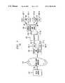
- FIG. 1shows, in simplified block diagram form, a video distribution system employing an embodiment of the invention.
- network 100including video server 101 which supplies down-stream video signals to broadband network 102 , in response to an up-stream communication including a selection message.
- Broadband network 102supplies the communications signals to and from optical line terminal 103 .
- optical line circuit (OLC) 104interfaces to an optical fiber line,
- the optical fiber lineis, for example, a power splitting passive optical network (PSPON) fiber including optical fibers 110 and 111 on which optical signals are transmitted using coarse wavelength division multiplexing.
- PSPONpower splitting passive optical network
- the PSPON fibers 110may be split via passive splitter 105 into a prescribed number of optical fibers 111 , for example, 32 fibers 111 , thereby interfacing via associated ONUs 106 with 32 locations.
- OLT 103serves one or more OLCs 104 , namely, 104 - 1 through 104 -Z, coupled to a corresponding number of fiber lines, namely, 110 - 1 through 110 -Z, respectively, and that an OLC 104 serves one or more ONUs 106 via optical fibers 111 - 1 through 111 -W.
- the down-stream transmission of video signalsis in asynchronous transfer mode (ATM) cells via time division multiplex (TDM), while up-stream transmission of communication is via time division multiple access (TDMA), and both down-stream and up-stream communications is at 155.52 Mb/sec.
- ATMasynchronous transfer mode
- TDMtime division multiplex
- TDMAtime division multiple access
- Efficient TDMA communications in the up-stream directionrequires all optical network units (ONUs) 106 to have equal loop delay in relationship to their associated OLC 104 .
- Thisis realized by employing a ranging procedure that is executed when each ONU 106 associated with a particular OLC 104 is installed, moved, returned to service, or the like.
- Thisis realized by employed a ranging procedure that is executed when each ONU 106 is installed.
- the ranging proceduredefines an artificial delay that when added to the transmission loop delay of an ONU 106 yields the required common loop delay.
- Such ranging arrangementsare known in the art. However, a preferred ranging arrangement is described in copending U.S. patent application Ser. No. 09/356,980 filed concurrently herewith and assigned to the assignee of this application.
- OLT 103is a special ATM switch including a traditional ATM fabric and input/output (I/O) ports.
- I/Oinput/output
- two types of I/O boardsare required, namely, standard SONET (synchronous optical network) boards, e.g., OC-12 units, and OLC units 104 .
- Video signals received from OLT 103 as ATM cells from one or more SONET boardsare distributed to the OLC units 104 . Because of this, up-stream channel select messages being sent to video services controller 202 in video server 101 are intercepted within the OLT 103 , which accumulates the number of viewers of each video program that is OLT 103 wide.
- SONETsynchronous optical network
- each of OLC units 104includes, in this example, a CPU and memory (not shown) that may be a microprocessor with memory.
- Optical network unit (ONU) 106terminates the PSPON fiber 110 via an associated PSPON optical fiber 111 , and provides appropriate interfaces, in this example, to one or more television sets (TVs) 107 - 1 through 107 -N.
- TVs 107 - 1 through 107 -Nhas an associated one of remote control (RC) units 108 - 1 through 108 -N, respectively.
- RCremote control
- Network 100supplies, for example, via one or more video services controller 202 in video server 101 in response to specific program requests, conventional broadcast TV programs, programs similar to those supplied via cable TV providers, satellite TV providers, video on demand and the like. Procedures for requesting and transmitting video programs are described in greater detail below.
- a residential video subsystemincludes an ONU 106 and one or more TVs 107 and associated RC units 108 .
- ONU 106 and TVs 107are interconnected via coaxial (COAX) cable.
- COAXcoaxial
- FIG. 2is a simplified block diagram of video server 101 employed in the system of FIG. 1 .
- video storage server 201receives video signals via inputs 204 - 1 through 204 -Y and supplied on a one-to-one basis to MPEG2 video encoders 203 - 1 through 203 -Y, respectively, where they are digitally encoded and compressed in now well known fashion. Thereafter, the digitally encoded MPEG2 video signals are supplied to video storage server 201 .
- video storage server 201stores the digitally encoded MPEG2 video signals, to be transmitted to subscribers.
- Video signalsmay be prestored in video storage server 201 to support, for example, video-on-demand, or directed advertisement insertion.
- the transmission of the digitally encoded MPEG2 video signalsis in response to control signals from a subscriber and supplied, in this example, via TDMA in ATM cells over transmission link 109 to video server 101 and, therein, via 207 to video services controller 202 .
- video services controller 202supplies/and or receives control signals to and/or from video storage server 201 .
- video storage server 201supplies appropriate video signals including advertisements during commercial intervals or in accordance with the service being provided to one or more subscribers.
- the video signalsare included in ATM cells and formatted as an ATM signal for transmission. Thereafter, the ATM formatted signal is supplied as an output from video server 201 via 206 to bi-directional transmission link 109 .
- FIG. 2shows a block diagram of the video server 101 consisting of a bank of MPEG2 video encoders 203 , a video storage server 201 , and a video services controller 202 .
- all encoded broadcast video signalsare delivered through the video storage server 201 . Therefore, each digital video signal stream is written to the video storage server 201 in real time, as well as, read from that server 201 in near real time.
- a read memory pointer in video services controller 202just simply follows the write pointer, also in controller 202 , by some non-zero amount. It is worth noting that the delay between the writing and the reading of a video signal stream is not important. In fact, one possible advanced video service that immediately follows is a “delayed broadcast on demand”.
- the video service controller 202manages the writing and reading of all video signal streams, providing independent address information for each digital video signal stream that is written and/or read, as well as ATM virtual circuit (VC) information.
- control operationse.g., “pause”, are also provided.
- dataare written in blocks that are divisible by 48 .
- ATM cellsare formatted as part of the server's I/O operations and an ATM formatted signal is supplied as an output via 206 .
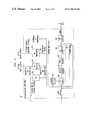
- FIG. 3shows, in simplified block diagram form, details of a centralized video controller, namely, one implementation of ONU 106 , employing an embodiment of the invention that may be employed in the system 100 of FIG. 1 .
- ONU 106includes at least one radio frequency (RF) receiver 301 , CPU 302 , one or more program units 303 - 1 through 303 -M and RF combiner 309 . It is noted that there must be at least “M” RF receivers 301 corresponding to the number “M” of program units 303 .
- the number of program units 303i.e., M, defines the number of video programs that can be viewed simultaneously by multiple TVs 107 within a location, e.g., a home.
- RF receiver 301receives RF signals including control messages from a remote control unit associated with a TV 107 (FIG. 1 ). This may be realized by employing a RF transmitter in the TV remote control unit, described below in conjunction with FIG. 4, and a RF receiver, both of a type used in a wireless, i.e., cordless, telephone, now well known in the art. Note that there may be a plurality of TVs and a corresponding plurality of remote control units. ONU 106 would include as many RF receivers as there are remote control units. RF control messages include, for example, the associated remote control unit identity (ID) and a selected channel number.
- IDthe associated remote control unit identity
- Other control messagesinclude, in addition to the remote control ID, for example, an indication that an associated TV has been either powered ON or powered OFF.
- the information received in the RF control messageis supplied to CPU 302 .
- CPU 302is, for example, a microprocessor including memory.
- CPU 302receives a RF transmission from a previously inactive remote control unit 108 , it assigns one of program units 303 to the TV 107 associated with the remote control unit 108 , it writes the VC corresponding to the received channel number into register 304 and determines that VC through use of a look-up table. It maintains a count of how many active TVs 107 are tuned to the selected program and it stores the selected channel for this TV 107 in a lookup table.
- CPU 302transmits a message up-stream to video server 101 and video services controller 202 , therein, requesting the transmission of the selected video program.
- the selected programis transmitted down-stream in ATM cells on the virtual circuit (VC) identified by the selected program channel number and received at the selected program unit 303 , in this example, program unit 303 - 1 .
- the selected channel number's VC and channel numberare supplied to virtual circuit (VC) filter 305 and to agile up-converter 308 , respectfully, to tune them to the selected program channel.
- the selected video programis received at ONU 106 and supplied to VC filter 305 as a sequence of ATM cells.
- VC filter 305filters the received signal to obtain the selected program channel signal as a MPEG2 digital video signal, i.e., a compressed digital video signal, that is supplied to MPEG2 decoder 306 .
- MPEG2 digital decoder 306yields an analog version of the selected video channel, which is supplied to NTSC encoder 307 where it is encoded.
- the NTSC encoded signalis then supplied to up-converter 308 , where the video signal is frequency converted to the selected standard video channel frequency, i.e., 6 MHz channel.
- up-converter 308is a so-called agile up-converter that adjusts its frequency to the frequency of the supplied program channel number.
- the resulting channel signalis supplied to RF combiner 309 where it is combined with channel signals from others of program units 303 , if any, and transmitting via COAX to one or more TVs 107 , i.e., all the TVs, at the location, e.g., a home.
- FIG. 4shows, in simplified block diagram form, details of a remote control unit 108 (FIG. 1 ), including an embodiment of the invention, that may be employed with the video controller of FIG. 3 .
- Shownis button pad 401 for keying a desired channel number that is supplied to RF transmitter 402 and infra red (IR) transmitter 403 .
- RF transmitter 402transmits to ONU 106 a RF signal, for example, a packet containing a message including the remote unit ID and the selected channel number.
- IR transmitter 403transmits an infra red signal in well known fashion to an associated TV 107 - 1 .
- a userturns ON the TV 107 - 1 by pressing an “ON” button on button pad 401 of remote control 108 - 1 .
- a wireless IR signal transmissionis made via IR transmitter 403 to the TV 107 - 1 , which turns its power ON in usual fashion.
- a wireless RF transmissionis made via RF transmitter 402 of a control packet containing the identification (ID) of the remote control unit 108 - 1 and a power ON command.
- ONU 106(FIG. 3) via CPU 302 retains knowledge of the channel that each TV 107 at the location was tuned to when the particular TV was last turned OFF, which is the channel that the TV should be initially tuned to when it is turned ON.
- ONU 106utilizes this retained information to perform two operations. First, if the previously viewed channel is not being viewed currently by another TV 107 , ONU 106 employs the information to insure that a MPEG2 decoder 306 , if one is available, and associated circuitry is assigned to the retained channel, i.e., to the corresponding ATM VC. Second, ONU 106 sends a control packet up-stream to video server 101 (FIG. 1) and, therein, to video services controller 202 , requesting that a program on the desired previously viewed channel be transmitted to the ONU 106 . Assuming that a MPEG2 decoder 306 is available, the associated TV now displays the program on the channel that the TV was last tuned to prior to being turned OFF.
- ONU 106appropriately formulates and passes up-stream messages via CPU 302 to the video server 101 and, therein, to a remote video services controller 202 requesting that the transmitted digital video program for that PSPON 110 and 111 be appropriately changed. Also, if not already assigned, a MPEG2 decoder 306 and associated circuitry are assigned.
- CPU 302retains information regarding the number of TVs 107 that are viewing each requested video program. When a requested video program is no longer being viewed by any of TVs 107 , CPU 302 transmits an up-stream message to video server 101 and, therein, to video services controller 202 indicating that the video program is no longer being viewed.
- the system operationmight be different. For example, if video-on-demand (VOD) is selected, the user is assigned an otherwise unused channel for point-to-point delivery of the interactive video preview/select program.
- VODvideo-on-demand
- the MPEG2 decoder 306for this example, is dedicated to that TV 107 , remote control 108 pair. Other TVs can also view that video, but its interactive control is disabled, as long as, the TV 107 associated with the initiating remote control 108 is still viewing the program.
- the initiating remote control 108is employed to select a different program, control of the VOD is relinquished and the next remote control 108 that attempts an interactive control function, e.g., pause, is assumed to be the initiating remote control 108 .
- other interactive TV applicationscan be accessed. For some interactive applications, such as games, multiple controlling remote controls 108 are appropriate. In such a situation, however, the application would typically distinguish between the active remote controls 108 .
- CPU 302(FIG. 3) receives a RF transmission from a previously inactive remote control unit 108 , it responds as follows:
- the COAX frequency allocationis identical to that used for conventional analog CATV configurations
- TV featuressuch as the LED display that shows the selected channel number, are still correct
- FIG. 5is a flow chart illustrating steps in the operational process of the centralized video controller of FIG. 3, namely, ONU 106 including agile up-converter 308 , in the system of FIG. 1 .
- parameters for each of program units (PUNs) 303 in ONU 106include number of viewers, PUN status and the program channel (CH).
- ONU 106waits to receive a RF message from a remote control unit 108 .
- step 501tests to determine if a message is being received. If the test result in step 501 is NO, step 501 just repeats until the test result is YES and a message has been received that yields a YES result.
- step 502causes the program channel (CH) to be set to the last selected channel CH (N), where “N” corresponds to the remote control unit 108 .
- PUNprogram unit
- CHprogram channel
- FIG. 6shows, in simplified block diagram form, details of another centralized video controller employing an embodiment of the invention that may be employed in the system of FIG. 1 .
- ONU 106includes at least one radio frequency (RF) receiver 301 and at least one associated RF transmitter 603 , CPU 302 , one or more program units 601 - 1 through 601 -M and RF combiner 309 .
- RFradio frequency
- the number of program units 601i.e., M, defines the number of video programs that can be simultaneously viewed by multiple TVs within a location, e.g., a home.
- RF receiver 301receives RF signals including control messages from a remote control unit associated with a TV 107 (FIG. 1 ).
- Thismay be realized by employing a RF transmitter 402 in the TV 107 remote control unit 108 , described below in conjunction with FIG. 7, and a RF receiver 301 , both of the type used in a wireless telephone, which are well known in the art.
- each RF receiver 301has an associated RF transmitter 603 for transmitting a “wireless” RF signal to an associated remote control unit 108 including the fixed channel number that up-converter 602 is tuned to, as described below.
- theremay be a plurality of TVs 107 and a corresponding plurality of remote control units 108 .
- ONU 106would include as many RF receivers and associated RF transmitters, as there are remote control units 108 .
- the received RF control messageincludes, for example, the associated remote control unit identity (ID) and a selected channel number.
- Other control messagesinclude, in addition to the remote control ID, an indication of an associated TV being either powered ON or Powered OFF.
- the information received in the RF control messageis supplied to CPU 302 .
- CPU 302is, for example, a microprocessor including memory.
- CPU 302retains a look-up table containing information indicating the last selected program channel number for each of TVs 107 , including those of TVs 107 that are currently inactive.
- CPU 302When CPU 302 receives a RF transmission from a previously inactive remote control unit 108 , it assigns one of program units 601 to the TV associated with the remote control unit, it writes the last selected program channel number into register 304 , it writes the RF video program channel number being used by the assigned program unit 601 to RF transmitter 603 which, in turn, transmits the RF signal to the RF receiver in an associated remote control unit 108 , it maintains a count of how many active TVs are tuned to the selected channel number and it stores the selected channel number for this TV 107 in a lookup table.
- CPU 302transmits a message up-stream to video server 101 and a video services controller 202 , therein, requesting the transmission of the selected channel.
- the selected channelis transmitted down-stream in ATM cells on the virtual circuit (VC) identified by the selected program channel number and received at the selected program unit 601 , in this example, program unit 601 - 1 .
- the selected channel number's VCis supplied to virtual circuit (VC) filter 305 to tune it to the selected program channel.
- the selected video program channelis received at ONU 106 and supplied to VC filter 305 as a sequence of ATM cells.
- VC filter 305obtains the selected program channel signal as a MPEG2 digital video signal that is supplied to MPEG2 decoder 306 .
- MPEG2 digital decoder 306yields an analog version of the selected video channel that is supplied to NTSC encoder 307 where it is encoded.
- the NTSC encoded signalis then supplied to up-converter 602 where the video signal is frequency converted to a predetermined standard video channel frequency, i.e., 6 MHz channel.
- the resulting channel signalis supplied to RF combiner 309 where it is combined with channel signals from others of program units 601 , if any, and transmitted via COAX to one or more TVs 107 at the location, e.g., a home.
- FIG. 7shows, in simplified block diagram form, details of a remote control unit 108 (FIG. 1 ), including an embodiment of the invention, that may be employed with the video controller 106 of FIG. 6 .
- Shownis button pad 401 for keying a desired channel number that is supplied to RF transmitter 402 .
- RF transmitter 402transmits a RF packet signal including the remote units ID and the selected channel number to ONU 106 .
- RF receiver 701receives the RF signal including the RF video program channel number of up-converter 602 of the assigned program unit 601 from RF transmitter 603 (FIG. 5) and supplies the channel number to IR transmitter 702 .
- IR transmitter 702transmits an infra red signal in well known fashion to an associated TV 107 .
- ONU 106 of FIG. 6has a fixed channel, i.e., RF frequency, assigned to each MPEG2 decoder 306 , actually its up-converter 602 . Therefore, the video signal from each MPEG2 decoder 306 of FIG. 6 is always transmitted on the same channel.
- a TV 107would be assigned a MPEG2 decoder 306 when it is turned ON. The VC is changed as channels are changed, but the TV 107 stays tuned to the channel number of the MPEG2 decoder 306 it was assigned.
- the userturns on the TV 107 by pressing the “power ON” button of the associated remote control 108 .
- Thisdirectly results in only one communications event.
- a “wireless” RF control packet containing the identification of the remote control, and the “power ON” commandis sent to the ONU 106 .
- the ONU 106retains knowledge of the channel each TV 107 was tuned to when it was last turned OFF and, therefore, the channel that should be initially delivered to that TV 107 to closely mimic conventional analog video delivery techniques.
- the ONU 106uses that information to perform three operations. First, it insures that a MPEG2 decoder 306 , if one is available, and associated circuitry is assigned to that video channel (i.e. that ATM VC).
- ONU 106sends a control packet up-stream to video server 101 and, therein, to video services controller 202 , requesting that the selected program channel, i.e., VC, be transmitted on that access PSPON fiber 110 and fiber 111 associated with the ONU 106 .
- the ONU 106transmits a return “wireless” control message back to the associated remote control 108 containing the channel number used by the assigned MPEG2 decoder 306 .
- the remote control 108sends an IR transmission to the associated TV 107 , turning its power ON, and tuning it to the designated channel. Assuming that a MPEG2 decoder 306 was available, that TV 107 now displays the program of the channel that TV was displaying when last turned OFF.
- the “wireless” RF control messagesare transmitted to the ONU 106 indicating those channel changes.
- the ONU 106appropriately changes the MPEG2 decoder's VC, and passes up-stream messages requesting that the transmitted digital video channels for that PSPON 110 and the associated fiber 11 be appropriately changed.
- a MPEG2 decoder 306If a MPEG2 decoder 306 is not available, which is only possible if there are more TVs 107 than decoders 306 , the TV 107 will display noise unless the selected channel is one already being decoded for another TV 107 . In that situation, a “wireless” RF control message is sent to the remote control 108 , and passed to the associated TV 107 using the IR link, appropriately changing TV channels. Only the remote control 108 that selected the program can change it. However, if that TV 107 is turned OFF, the next remote control 108 to attempt to change the channel will be given control of that MPEG2 decoder 306 .
- CPU 302(FIG. 6) receives a RF transmission from a previously inactive remote control unit 108 , it responds as follows:
- the up-converter 608need not be frequency agile.
- FIG. 8is a flow chart illustrating steps in the operational process of the centralized video controller of FIG. 6 in the system of FIG. 1 .
- ONU 106including fixed frequency up-converter 608 , in the system of FIG. 1 .
- parameters for each of program units (PUNs) 601 in ONU 106include PUN status and the program channel (CH).
- ONU 106waits to receive a RF message from a remote control unit 108 .
- step 801tests to determine if a message is being received. If the test result in step 801 is NO, step 801 just repeats until the test result is YES, and a message has been received that yields a YES result.
- step 815which tests to determine if the message is power OFF, if the test result is YES, control is returned to step 801 . If the test result in step 815 is NO, control is transferred to step 813 .
- a locatione.g., a house
Landscapes
- Engineering & Computer Science (AREA)
- Multimedia (AREA)
- Signal Processing (AREA)
- Human Computer Interaction (AREA)
- General Engineering & Computer Science (AREA)
- Software Systems (AREA)
- Details Of Television Systems (AREA)
- Two-Way Televisions, Distribution Of Moving Picture Or The Like (AREA)
- Data Exchanges In Wide-Area Networks (AREA)
Abstract
Description
Claims (36)
Priority Applications (4)
| Application Number | Priority Date | Filing Date | Title |
|---|---|---|---|
| US09/356,978US6796555B1 (en) | 1999-07-19 | 1999-07-19 | Centralized video controller for controlling distribution of video signals |
| EP00305858.3AEP1071288B1 (en) | 1999-07-19 | 2000-07-11 | Video controller |
| CA002313844ACA2313844C (en) | 1999-07-19 | 2000-07-11 | Video controller |
| JP2000217061AJP4812158B2 (en) | 1999-07-19 | 2000-07-18 | Video control device |
Applications Claiming Priority (1)
| Application Number | Priority Date | Filing Date | Title |
|---|---|---|---|
| US09/356,978US6796555B1 (en) | 1999-07-19 | 1999-07-19 | Centralized video controller for controlling distribution of video signals |
Publications (1)
| Publication Number | Publication Date |
|---|---|
| US6796555B1true US6796555B1 (en) | 2004-09-28 |
Family
ID=23403781
Family Applications (1)
| Application Number | Title | Priority Date | Filing Date |
|---|---|---|---|
| US09/356,978Expired - LifetimeUS6796555B1 (en) | 1999-07-19 | 1999-07-19 | Centralized video controller for controlling distribution of video signals |
Country Status (4)
| Country | Link |
|---|---|
| US (1) | US6796555B1 (en) |
| EP (1) | EP1071288B1 (en) |
| JP (1) | JP4812158B2 (en) |
| CA (1) | CA2313844C (en) |
Cited By (96)
| Publication number | Priority date | Publication date | Assignee | Title |
|---|---|---|---|---|
| US20010032333A1 (en)* | 2000-02-18 | 2001-10-18 | Gregory Flickinger | Scheduling and presenting IPG ads in conjunction with programming ads in a television environment |
| US20020056107A1 (en)* | 2000-08-31 | 2002-05-09 | Schlack John A. | System and method for delivering statistically scheduled advertisements |
| US20020083442A1 (en)* | 2000-08-31 | 2002-06-27 | Eldering Charles A. | Queue-based head-end advertisement scheduling method and apparatus |
| US20020083439A1 (en)* | 2000-08-31 | 2002-06-27 | Eldering Charles A. | System for rescheduling and inserting advertisements |
| US20020083445A1 (en)* | 2000-08-31 | 2002-06-27 | Flickinger Gregory C. | Delivering targeted advertisements to the set-top-box |
| US20020083474A1 (en)* | 2000-12-27 | 2002-06-27 | Earl Hennenhoefer | Intelligent device system and method for distribution of digital signals on a wideband signal distribution system |
| US20020083443A1 (en)* | 2000-08-31 | 2002-06-27 | Eldering Charles A. | Advertisement distribution system for distributing targeted advertisements in television systems |
| US20020087980A1 (en)* | 2000-12-28 | 2002-07-04 | Eldering Charles A. | Grouping advertisement subavails |
| US20020087975A1 (en)* | 2000-08-31 | 2002-07-04 | Schlack John A. | System and method for delivering targeted advertisements using multiple presentation streams |
| US20020108050A1 (en)* | 2000-08-28 | 2002-08-08 | Contentguard Holdings, Inc. | System and method for digital rights management using a standard rendering engine |
| US20020144263A1 (en)* | 2000-08-31 | 2002-10-03 | Eldering Charles A. | Grouping of advertisements on an advertising channel in a targeted advertisement system |
| US20030144869A1 (en)* | 2001-11-20 | 2003-07-31 | Contentguard Holdings, Inc. | Extensible rights expression processing system |
| US20030182142A1 (en)* | 2001-11-20 | 2003-09-25 | Contentguard Holdings, Inc. | Systems and methods for creating, manipulating and processing rights and contract expressions using tokenized templates |
| US20040024670A1 (en)* | 2002-04-29 | 2004-02-05 | Contentguard Holdings, Inc. | Rights management system using legality expression language |
| US20040039704A1 (en)* | 2001-01-17 | 2004-02-26 | Contentguard Holdings, Inc. | System and method for supplying and managing usage rights of users and suppliers of items |
| US20040133920A1 (en)* | 2002-12-18 | 2004-07-08 | Yongtae Kim | Digital broadcast system in passive optical network |
| US20040160971A1 (en)* | 2002-11-27 | 2004-08-19 | Edward Krause | Apparatus and method for dynamic channel mapping and optimized scheduling of data packets |
| US20040162784A1 (en)* | 2001-05-31 | 2004-08-19 | Bijan Tadayon | Method and apparatus for dynamically assigning usage rights to digital works |
| US20040172652A1 (en)* | 2001-02-09 | 2004-09-02 | Fisk Julian Basil | Distribution and networking of television, video and other signals, installation of such distribution systems, and control of television sets |
| US20040187160A1 (en)* | 2003-03-17 | 2004-09-23 | Qwest Communications International Inc. | Methods and systems for providing video on demand |
| US20040203709A1 (en)* | 2002-11-08 | 2004-10-14 | Louis Luneau | Flexible software radio transceiver |
| US20040203374A1 (en)* | 2002-10-28 | 2004-10-14 | Nokia Corporation | Graphical indication of a proximately located device |
| US20040205821A1 (en)* | 2001-08-13 | 2004-10-14 | Eugene Yamada | Tv rf switching system |
| US20040228345A1 (en)* | 2003-05-16 | 2004-11-18 | Kyu-Hyung Cho | Apparatus and method for switching broadcast channel using VCC information |
| US20040230529A1 (en)* | 2001-11-20 | 2004-11-18 | Contentguard Holdings, Inc. | System and method for granting access to an item or permission to use an item based on configurable conditions |
| US20040236717A1 (en)* | 2002-03-14 | 2004-11-25 | Demartini Thomas M. | Rights expression profile system and method |
| US20040244051A1 (en)* | 2003-06-02 | 2004-12-02 | Sang-Ho Kim | Method and optical transport network for providingbroadcasting services |
| US20040267552A1 (en)* | 2003-06-26 | 2004-12-30 | Contentguard Holdings, Inc. | System and method for controlling rights expressions by stakeholders of an item |
| US20050097593A1 (en)* | 2003-11-05 | 2005-05-05 | Michael Raley | System, method and device for selected content distribution |
| US20050152697A1 (en)* | 2004-01-12 | 2005-07-14 | Ki-Cheol Lee | Ethernet PON using time division multiplexing to converge broadcasting/video with data |
| US20050229203A1 (en)* | 2004-04-13 | 2005-10-13 | Jutzi Curtis E | System and method for dynamic channel management of a television based on media center set-top box tuner availability |
| US20060013260A1 (en)* | 2004-06-28 | 2006-01-19 | Advanced Fibre Communications, Inc. | Optical line termination system, method and apparatus for bus management, and method and apparatus for signal concentration |
| US20060107046A1 (en)* | 2004-11-18 | 2006-05-18 | Contentguard Holdings, Inc. | Method, system, and device for license-centric content consumption |
| US20060107326A1 (en)* | 2004-11-12 | 2006-05-18 | Demartini Thomas | Method, system, and device for verifying authorized issuance of a rights expression |
| US20060106726A1 (en)* | 2004-11-18 | 2006-05-18 | Contentguard Holdings, Inc. | Method, system, and device for license-centric content consumption |
| US20060112015A1 (en)* | 2004-11-24 | 2006-05-25 | Contentguard Holdings, Inc. | Method, system, and device for handling creation of derivative works and for adapting rights to derivative works |
| US20060129493A1 (en)* | 1994-11-23 | 2006-06-15 | Contentguard Holdings, Inc. | Usage rights grammar and digital works having usage rights created with the grammar |
| US20060238648A1 (en)* | 2005-04-20 | 2006-10-26 | Eric Wogsberg | Audiovisual signal routing and distribution system |
| US20060239294A1 (en)* | 2005-04-20 | 2006-10-26 | Jupiter Systems | Capture node for use in an audiovisual signal routing and distribution system |
| US20060242669A1 (en)* | 2005-04-20 | 2006-10-26 | Jupiter Systems | Display node for use in an audiovisual signal routing and distribution system |
| US20060248573A1 (en)* | 2005-04-28 | 2006-11-02 | Content Guard Holdings, Inc. | System and method for developing and using trusted policy based on a social model |
| US20070078777A1 (en)* | 2005-09-29 | 2007-04-05 | Contentguard Holdings, Inc. | System and method for digital rights management using advanced copy with issue rights, and managed copy tokens |
| US20070094145A1 (en)* | 2005-10-24 | 2007-04-26 | Contentguard Holdings, Inc. | Method and system to support dynamic rights and resources sharing |
| US20070143806A1 (en)* | 2005-12-17 | 2007-06-21 | Pan Shaoher X | Wireless system for television and data communications |
| US7382982B2 (en)* | 2003-09-26 | 2008-06-03 | Samsung Electronics Co., Ltd. | Ethernet passive optical network for integrating broadcast and communication based on time division multiplexing scheme |
| US7412605B2 (en) | 2000-08-28 | 2008-08-12 | Contentguard Holdings, Inc. | Method and apparatus for variable encryption of data |
| US20080320599A1 (en)* | 2002-03-14 | 2008-12-25 | Contentguart Holdings, Inc. | Rights expression profile system and method using templates |
| US7500258B1 (en) | 1999-05-10 | 2009-03-03 | Prime Research Alliance E., Inc. | Advertisement subgroups for digital streams |
| US20090067433A1 (en)* | 2007-09-12 | 2009-03-12 | The Directv Group, Inc. | Method and system for controlling a back-up network adapter in a local collection facility from a remote facility |
| US20090068959A1 (en)* | 2007-09-11 | 2009-03-12 | The Directv Group, Inc. | Method and system for operating a receiving circuit for multiple types of input channel signals |
| US20090070838A1 (en)* | 2007-09-11 | 2009-03-12 | The Directv Group, Inc. | Method and system for communicating between a local collection facility and a remote facility |
| US20090070822A1 (en)* | 2007-09-11 | 2009-03-12 | The Directv Group, Inc. | Method and System for Monitoring and Simultaneously Displaying a Plurality of Signal Channels in a Communication System |
| US20090113490A1 (en)* | 2007-10-30 | 2009-04-30 | Wasden Mitchell B | Method and system for monitoring and controlling a local collection facility from a remote facility through an ip network |
| US20090110052A1 (en)* | 2007-10-30 | 2009-04-30 | Wasden Mitchell B | Method and system for monitoring and controlling a back-up receiver in local collection facility from a remote facility using an ip network |
| US7587731B1 (en)* | 1999-07-30 | 2009-09-08 | Sony Corporation | Program guide information providing device, program device information providing system, information receiving device, remote operating system, and method thereof |
| US7609848B2 (en) | 2000-12-29 | 2009-10-27 | Contentguard Holdings, Inc. | Multi-stage watermarking process and system |
| US20090278996A1 (en)* | 2006-12-22 | 2009-11-12 | Koninklijke Kpn N.V. The Hague, The Netherlands | Method and system for selecting a broadcast-signal in a multi-user environment |
| US7633966B2 (en) | 2000-04-19 | 2009-12-15 | Mosaid Technologies Incorporated | Network combining wired and non-wired segments |
| US20100050272A1 (en)* | 2001-05-31 | 2010-02-25 | Contentguard Holdings, Inc. | Method and apparatus for hierarchical assignment of rights to documents and documents having such rights |
| US7698723B2 (en) | 2000-12-28 | 2010-04-13 | At&T Intellectual Property I, L.P. | System and method for multimedia on demand services |
| US20100115561A1 (en)* | 2008-11-04 | 2010-05-06 | The Directv Group, Inc. | Method and system for operating a receiving circuit for multiple types of input channel signals |
| US7725401B2 (en) | 2001-05-31 | 2010-05-25 | Contentguard Holdings, Inc. | Method and apparatus for establishing usage rights for digital content to be created in the future |
| US7765403B2 (en) | 1997-02-28 | 2010-07-27 | Contentguard Holdings, Inc. | System for controlling the distribution and use of rendered digital works through watermarking |
| US7774280B2 (en) | 2001-06-07 | 2010-08-10 | Contentguard Holdings, Inc. | System and method for managing transfer of rights using shared state variables |
| US7774279B2 (en) | 2001-05-31 | 2010-08-10 | Contentguard Holdings, Inc. | Rights offering and granting |
| US7809644B2 (en) | 1994-11-23 | 2010-10-05 | Contentguard Holdings, Inc. | Digital work structure |
| US7810114B2 (en) | 2000-08-31 | 2010-10-05 | Prime Research Alliance E., Inc. | Advertisement filtering and storage for targeted advertisement systems |
| US7853531B2 (en) | 2001-06-07 | 2010-12-14 | Contentguard Holdings, Inc. | Method and apparatus for supporting multiple trust zones in a digital rights management system |
| US20110038630A1 (en)* | 2002-09-03 | 2011-02-17 | Hitachi, Ltd. | Packet communicating apparatus |
| US20110131608A1 (en)* | 1999-05-18 | 2011-06-02 | Sony Corporation | Receiving apparatus and receiving method, broadcasting apparatus and broadcasting method, information processing apparatus and information procesing method, bidirectional communication system and bidirectional communication method, and providing medium |
| US8001053B2 (en) | 2001-05-31 | 2011-08-16 | Contentguard Holdings, Inc. | System and method for rights offering and granting using shared state variables |
| US8069116B2 (en) | 2001-01-17 | 2011-11-29 | Contentguard Holdings, Inc. | System and method for supplying and managing usage rights associated with an item repository |
| US8099364B2 (en) | 2001-05-31 | 2012-01-17 | Contentguard Holdings, Inc. | Digital rights management of content when content is a future live event |
| US8151295B1 (en) | 2000-08-31 | 2012-04-03 | Prime Research Alliance E., Inc. | Queue based advertisement scheduling and sales |
| US8180675B2 (en) | 2000-08-31 | 2012-05-15 | Prime Research Alliance E., Inc. | System and method for automatically managing avail inventory data and avail pricing |
| US20120141140A1 (en)* | 2010-12-07 | 2012-06-07 | Alcatel-Lucent Usa Inc. | Distribution of optical power in an optical transport system |
| US8244579B2 (en) | 2001-01-17 | 2012-08-14 | Contentguard Holdings, Inc. | Method and apparatus for distributing enforceable property rights |
| US8271350B2 (en) | 2000-11-03 | 2012-09-18 | Contentguard Holdings, Inc. | Method and system for automatically publishing content |
| US8275709B2 (en) | 2001-05-31 | 2012-09-25 | Contentguard Holdings, Inc. | Digital rights management of content when content is a future live event |
| US8275716B2 (en) | 2001-05-31 | 2012-09-25 | Contentguard Holdings, Inc. | Method and system for subscription digital rights management |
| US8442916B2 (en) | 2001-05-31 | 2013-05-14 | Contentguard Holdings, Inc. | Digital rights management of content when content is a future live event |
| US8601519B1 (en) | 2000-12-28 | 2013-12-03 | At&T Intellectual Property I, L.P. | Digital residential entertainment system |
| US8606949B2 (en) | 2005-04-20 | 2013-12-10 | Jupiter Systems | Interconnection mechanism for multiple data streams |
| US8677423B2 (en) | 2000-12-28 | 2014-03-18 | At&T Intellectual Property I, L. P. | Digital residential entertainment system |
| US20140233909A1 (en)* | 2002-04-04 | 2014-08-21 | Broadcom Corporation | System and method supporting infrared remote control over a network |
| US20140281988A1 (en)* | 2013-03-12 | 2014-09-18 | Tivo Inc. | Gesture-Based Wireless Media Streaming System |
| US8988986B2 (en) | 2007-09-12 | 2015-03-24 | The Directv Group, Inc. | Method and system for controlling a back-up multiplexer in a local collection facility from a remote facility |
| US9049037B2 (en) | 2007-10-31 | 2015-06-02 | The Directv Group, Inc. | Method and system for monitoring and encoding signals in a local facility and communicating the signals between a local collection facility and a remote facility using an IP network |
| US9313457B2 (en) | 2007-09-11 | 2016-04-12 | The Directv Group, Inc. | Method and system for monitoring a receiving circuit module and controlling switching to a back-up receiving circuit module at a local collection facility from a remote facility |
| US9351045B1 (en) | 2002-06-21 | 2016-05-24 | Music Choice | Systems and methods for providing a broadcast entertainment service and an on-demand entertainment service |
| JP2017143371A (en)* | 2016-02-09 | 2017-08-17 | 日本電信電話株式会社 | Passive optical network system and video distribution method |
| US9831971B1 (en) | 2011-04-05 | 2017-11-28 | The Directv Group, Inc. | Method and system for operating a communication system encoded into multiple independently communicated encoding formats |
| US10219027B1 (en) | 2014-10-24 | 2019-02-26 | Music Choice | System for providing music content to a user |
| US10303357B2 (en) | 2010-11-19 | 2019-05-28 | TIVO SOLUTIONS lNC. | Flick to send or display content |
| US10390093B1 (en) | 2012-04-26 | 2019-08-20 | Music Choice | Automatic on-demand navigation based on meta-data broadcast with media content |
| US10986165B2 (en) | 2004-01-13 | 2021-04-20 | May Patents Ltd. | Information device |
Families Citing this family (4)
| Publication number | Priority date | Publication date | Assignee | Title |
|---|---|---|---|---|
| US20040213532A1 (en)* | 2002-07-10 | 2004-10-28 | Wyatt Frank Burkhead | Hybrid fiber-coaxial networks and broadband communications systems employing same |
| JP4040479B2 (en) | 2003-01-21 | 2008-01-30 | 三菱電機株式会社 | Information distribution apparatus and information distribution method |
| US7873977B2 (en) | 2004-05-07 | 2011-01-18 | Thomson Licensing | Method for controlling a multi-tuner signal receiving apparatus |
| CN104410844A (en)* | 2014-10-30 | 2015-03-11 | 成都康特电子高新科技有限责任公司 | Multifunctional HFC system based on radio and TV network |
Citations (16)
| Publication number | Priority date | Publication date | Assignee | Title |
|---|---|---|---|---|
| US4566034A (en) | 1983-05-02 | 1986-01-21 | Rca Corporation | Remote control transmitter arrangement for one or more television devices |
| US5574440A (en) | 1993-12-28 | 1996-11-12 | Kurtz; Fred R. | RF switching with remote controllers dedicated to other devices |
| US5708961A (en)* | 1995-05-01 | 1998-01-13 | Bell Atlantic Network Services, Inc. | Wireless on-premises video distribution using digital multiplexing |
| US5721829A (en)* | 1995-05-05 | 1998-02-24 | Microsoft Corporation | System for automatic pause/resume of content delivered on a channel in response to switching to and from that channel and resuming so that a portion of the content is repeated |
| US5734652A (en)* | 1995-09-27 | 1998-03-31 | Microsoft Corporation | ATM extended autoregistration and VPI/VCI assignment in a hybrid fiber-coax cable network |
| GB2322528A (en) | 1997-02-20 | 1998-08-26 | Motorola Inc | Broadband interactive media |
| US5872589A (en) | 1994-03-18 | 1999-02-16 | Interactive Return Service, Inc. | Interactive TV system for mass media distribution |
| US5969714A (en)* | 1994-09-15 | 1999-10-19 | Northern Telecom Limited | Interactive video system with frame reference number |
| US6111882A (en)* | 1996-08-22 | 2000-08-29 | Fujitsu Limited | On-demand system |
| US6188687B1 (en)* | 1994-11-30 | 2001-02-13 | Verizon Laboratories Inc. | Broadband switch that manages traffic and method therefor |
| US6211901B1 (en)* | 1995-06-30 | 2001-04-03 | Fujitsu Limited | Video data distributing device by video on demand |
| US6243388B1 (en)* | 1994-11-30 | 2001-06-05 | Verizon Laboratories Inc. | Broadband video switch that performs program merging and method therefor |
| US6362908B1 (en)* | 1998-12-02 | 2002-03-26 | Marconi Communications, Inc. | Multi-service adaptable optical network unit |
| US6385167B1 (en)* | 1998-08-13 | 2002-05-07 | Fujitsu Limited | ATM switch and method for controlling bandwidth and connection quality ATM connection |
| US6411773B1 (en)* | 1995-03-31 | 2002-06-25 | Sony Europa B.V. | Storage medium unit for storing information data, preferably video data and/or audio data |
| US6594826B1 (en)* | 1995-05-26 | 2003-07-15 | Irdeto Access, Inc. | Video pedestal network |
Family Cites Families (2)
| Publication number | Priority date | Publication date | Assignee | Title |
|---|---|---|---|---|
| JP2933133B2 (en)* | 1997-01-28 | 1999-08-09 | 日本電気株式会社 | Digital video signal multiplexing and separation systems |
| CA2313846C (en)* | 1999-07-19 | 2005-01-11 | Lucent Technologies Inc. | Television advertisement delivery system and method |
- 1999
- 1999-07-19USUS09/356,978patent/US6796555B1/ennot_activeExpired - Lifetime
- 2000
- 2000-07-11CACA002313844Apatent/CA2313844C/ennot_activeExpired - Fee Related
- 2000-07-11EPEP00305858.3Apatent/EP1071288B1/ennot_activeExpired - Lifetime
- 2000-07-18JPJP2000217061Apatent/JP4812158B2/ennot_activeExpired - Fee Related
Patent Citations (16)
| Publication number | Priority date | Publication date | Assignee | Title |
|---|---|---|---|---|
| US4566034A (en) | 1983-05-02 | 1986-01-21 | Rca Corporation | Remote control transmitter arrangement for one or more television devices |
| US5574440A (en) | 1993-12-28 | 1996-11-12 | Kurtz; Fred R. | RF switching with remote controllers dedicated to other devices |
| US5872589A (en) | 1994-03-18 | 1999-02-16 | Interactive Return Service, Inc. | Interactive TV system for mass media distribution |
| US5969714A (en)* | 1994-09-15 | 1999-10-19 | Northern Telecom Limited | Interactive video system with frame reference number |
| US6188687B1 (en)* | 1994-11-30 | 2001-02-13 | Verizon Laboratories Inc. | Broadband switch that manages traffic and method therefor |
| US6243388B1 (en)* | 1994-11-30 | 2001-06-05 | Verizon Laboratories Inc. | Broadband video switch that performs program merging and method therefor |
| US6411773B1 (en)* | 1995-03-31 | 2002-06-25 | Sony Europa B.V. | Storage medium unit for storing information data, preferably video data and/or audio data |
| US5708961A (en)* | 1995-05-01 | 1998-01-13 | Bell Atlantic Network Services, Inc. | Wireless on-premises video distribution using digital multiplexing |
| US5721829A (en)* | 1995-05-05 | 1998-02-24 | Microsoft Corporation | System for automatic pause/resume of content delivered on a channel in response to switching to and from that channel and resuming so that a portion of the content is repeated |
| US6594826B1 (en)* | 1995-05-26 | 2003-07-15 | Irdeto Access, Inc. | Video pedestal network |
| US6211901B1 (en)* | 1995-06-30 | 2001-04-03 | Fujitsu Limited | Video data distributing device by video on demand |
| US5734652A (en)* | 1995-09-27 | 1998-03-31 | Microsoft Corporation | ATM extended autoregistration and VPI/VCI assignment in a hybrid fiber-coax cable network |
| US6111882A (en)* | 1996-08-22 | 2000-08-29 | Fujitsu Limited | On-demand system |
| GB2322528A (en) | 1997-02-20 | 1998-08-26 | Motorola Inc | Broadband interactive media |
| US6385167B1 (en)* | 1998-08-13 | 2002-05-07 | Fujitsu Limited | ATM switch and method for controlling bandwidth and connection quality ATM connection |
| US6362908B1 (en)* | 1998-12-02 | 2002-03-26 | Marconi Communications, Inc. | Multi-service adaptable optical network unit |
Non-Patent Citations (1)
| Title |
|---|
| European Patent Office Search Report, Dated Jan. 31, 2002, 3 pages. |
Cited By (217)
| Publication number | Priority date | Publication date | Assignee | Title |
|---|---|---|---|---|
| US9953328B2 (en) | 1994-11-23 | 2018-04-24 | Contentguard Holdings, Inc. | Method and system for conducting transactions between repositories |
| US7788182B2 (en) | 1994-11-23 | 2010-08-31 | Contentguard Holdings, Inc. | Method for loaning digital works |
| US7970709B2 (en) | 1994-11-23 | 2011-06-28 | Contentguard Holdings, Inc. | Method and apparatus for client customization by executing software parts on plural servers |
| US8170955B2 (en) | 1994-11-23 | 2012-05-01 | Contentguard Holdings, Inc. | System and method for enforcing usage rights associated with digital content |
| US7664708B2 (en) | 1994-11-23 | 2010-02-16 | Contentguard Holdings, Inc. | System for controlling the distribution and use of digital works using digital tickets |
| US20060129493A1 (en)* | 1994-11-23 | 2006-06-15 | Contentguard Holdings, Inc. | Usage rights grammar and digital works having usage rights created with the grammar |
| US7809644B2 (en) | 1994-11-23 | 2010-10-05 | Contentguard Holdings, Inc. | Digital work structure |
| US20060167801A1 (en)* | 1994-11-23 | 2006-07-27 | Contentguard Holdings, Inc. | Method and apparatus for client customization by executing software parts on plural servers |
| US20060129492A1 (en)* | 1994-11-23 | 2006-06-15 | Contentguard Holdings, Inc. | Usage rights grammar and digital works having usage rights created with the grammar |
| US7523072B2 (en) | 1994-11-23 | 2009-04-21 | Contentguard Holdings, Inc. | System for controlling the distribution and use of digital works |
| US8205089B2 (en) | 1997-02-28 | 2012-06-19 | Contentguard Holdings, Inc. | System for controlling the distribution and use of rendered digital works through watermarking |
| US7765403B2 (en) | 1997-02-28 | 2010-07-27 | Contentguard Holdings, Inc. | System for controlling the distribution and use of rendered digital works through watermarking |
| US7500258B1 (en) | 1999-05-10 | 2009-03-03 | Prime Research Alliance E., Inc. | Advertisement subgroups for digital streams |
| US8108886B1 (en)* | 1999-05-18 | 2012-01-31 | Sony Corporation | Receiving apparatus and receiving method, broadcasting apparatus and broadcasting method, information processing apparatus and information processing method, bidirectional communication system and bidirectional communication method, and providing medium |
| US8918800B2 (en)* | 1999-05-18 | 2014-12-23 | Sony Corporation | Receiving apparatus and receiving method, broadcasting apparatus and broadcasting method, information processing apparatus and information processing method, bidirectional communication system and bidirectional communication method, and providing medium |
| US20110131608A1 (en)* | 1999-05-18 | 2011-06-02 | Sony Corporation | Receiving apparatus and receiving method, broadcasting apparatus and broadcasting method, information processing apparatus and information procesing method, bidirectional communication system and bidirectional communication method, and providing medium |
| US7587731B1 (en)* | 1999-07-30 | 2009-09-08 | Sony Corporation | Program guide information providing device, program device information providing system, information receiving device, remote operating system, and method thereof |
| US10587932B1 (en) | 2000-02-18 | 2020-03-10 | Prime Research Alliance E, Llc | Scheduling and presenting IPG ads in conjunction with programming ads in a television environment |
| US10034062B1 (en) | 2000-02-18 | 2018-07-24 | Prime Research Alliance E, Inc. | Scheduling and presenting IPG ads in conjunction with programming ads in a television environment |
| US20010032333A1 (en)* | 2000-02-18 | 2001-10-18 | Gregory Flickinger | Scheduling and presenting IPG ads in conjunction with programming ads in a television environment |
| US8671426B2 (en) | 2000-02-18 | 2014-03-11 | Prime Research Alliance E, Inc. | Scheduling and presenting IPG ads in conjunction with programming ads in a television environment |
| US8042131B2 (en) | 2000-02-18 | 2011-10-18 | Prime Research Alliance E, Inc. | Scheduling and presenting IPG ads in conjunction with programming ads in a television environment of application |
| US7653923B2 (en) | 2000-02-18 | 2010-01-26 | Prime Research Alliance E, Inc. | Scheduling and presenting IPG ads in conjunction with programming ads in a television environment |
| US8982903B2 (en) | 2000-04-19 | 2015-03-17 | Conversant Intellectual Property Management Inc. | Network combining wired and non-wired segments |
| US8982904B2 (en) | 2000-04-19 | 2015-03-17 | Conversant Intellectual Property Management Inc. | Network combining wired and non-wired segments |
| US7633966B2 (en) | 2000-04-19 | 2009-12-15 | Mosaid Technologies Incorporated | Network combining wired and non-wired segments |
| US8873586B2 (en) | 2000-04-19 | 2014-10-28 | Conversant Intellectual Property Management Incorporated | Network combining wired and non-wired segments |
| US8873575B2 (en) | 2000-04-19 | 2014-10-28 | Conversant Intellectual Property Management Incorporated | Network combining wired and non-wired segments |
| US8867506B2 (en) | 2000-04-19 | 2014-10-21 | Conversant Intellectual Property Management Incorporated | Network combining wired and non-wired segments |
| US8848725B2 (en) | 2000-04-19 | 2014-09-30 | Conversant Intellectual Property Management Incorporated | Network combining wired and non-wired segments |
| US8289991B2 (en) | 2000-04-19 | 2012-10-16 | Mosaid Technologies Incorporated | Network combining wired and non-wired segments |
| US7933297B2 (en) | 2000-04-19 | 2011-04-26 | Mosaid Technologies Incorporated | Network combining wired and non-wired segments |
| US7715441B2 (en) | 2000-04-19 | 2010-05-11 | Mosaid Technologies Incorporated | Network combining wired and non-wired segments |
| US7636373B2 (en) | 2000-04-19 | 2009-12-22 | Mosaid Technologies Incorporated | Network combining wired and non-wired segments |
| US7876767B2 (en) | 2000-04-19 | 2011-01-25 | Mosaid Technologies Incorporated | Network combining wired and non-wired segments |
| US7412605B2 (en) | 2000-08-28 | 2008-08-12 | Contentguard Holdings, Inc. | Method and apparatus for variable encryption of data |
| US8489900B2 (en) | 2000-08-28 | 2013-07-16 | Contentguard Holdings, Inc. | Method and apparatus for providing a specific user interface in a system for managing content |
| US8832852B2 (en) | 2000-08-28 | 2014-09-09 | Contentguard Holdings, Inc. | Method and apparatus for dynamic protection of static and dynamic content |
| US8225414B2 (en) | 2000-08-28 | 2012-07-17 | Contentguard Holdings, Inc. | Method and apparatus for identifying installed software and regulating access to content |
| US7913095B2 (en) | 2000-08-28 | 2011-03-22 | Contentguard Holdings, Inc. | Method and apparatus for providing a specific user interface in a system for managing content |
| US20020108050A1 (en)* | 2000-08-28 | 2002-08-08 | Contentguard Holdings, Inc. | System and method for digital rights management using a standard rendering engine |
| US7743259B2 (en) | 2000-08-28 | 2010-06-22 | Contentguard Holdings, Inc. | System and method for digital rights management using a standard rendering engine |
| US7603319B2 (en) | 2000-08-28 | 2009-10-13 | Contentguard Holdings, Inc. | Method and apparatus for preserving customer identity in on-line transactions |
| US9232252B2 (en) | 2000-08-31 | 2016-01-05 | Prime Research Alliance E., Inc. | Queue-based head-end advertisement scheduling method and apparatus |
| US20020144263A1 (en)* | 2000-08-31 | 2002-10-03 | Eldering Charles A. | Grouping of advertisements on an advertising channel in a targeted advertisement system |
| US20020056107A1 (en)* | 2000-08-31 | 2002-05-09 | Schlack John A. | System and method for delivering statistically scheduled advertisements |
| US20020083442A1 (en)* | 2000-08-31 | 2002-06-27 | Eldering Charles A. | Queue-based head-end advertisement scheduling method and apparatus |
| US7152237B2 (en) | 2000-08-31 | 2006-12-19 | Prime Research Alliance E., Inc. | Delivering targeted advertisements to the set-top-box |
| US7185353B2 (en) | 2000-08-31 | 2007-02-27 | Prime Research Alliance E., Inc. | System and method for delivering statistically scheduled advertisements |
| US8180675B2 (en) | 2000-08-31 | 2012-05-15 | Prime Research Alliance E., Inc. | System and method for automatically managing avail inventory data and avail pricing |
| US8443385B1 (en) | 2000-08-31 | 2013-05-14 | Prime Research Alliance E, Inc. | System and method for delivering statistically scheduled advertisements |
| US8151295B1 (en) | 2000-08-31 | 2012-04-03 | Prime Research Alliance E., Inc. | Queue based advertisement scheduling and sales |
| US7228555B2 (en) | 2000-08-31 | 2007-06-05 | Prime Research Alliance E., Inc. | System and method for delivering targeted advertisements using multiple presentation streams |
| US7039932B2 (en) | 2000-08-31 | 2006-05-02 | Prime Research Alliance E., Inc. | Queue-based head-end advertisement scheduling method and apparatus |
| US7328448B2 (en) | 2000-08-31 | 2008-02-05 | Prime Research Alliance E, Inc. | Advertisement distribution system for distributing targeted advertisements in television systems |
| US8789091B2 (en) | 2000-08-31 | 2014-07-22 | Prime Research Alliance E., Inc. | Queue based advertisement scheduling and sales |
| US20050278743A1 (en)* | 2000-08-31 | 2005-12-15 | Prime Research Alliance E., Inc. | Delivering targeted advertisements to the set-top-box |
| US20020083439A1 (en)* | 2000-08-31 | 2002-06-27 | Eldering Charles A. | System for rescheduling and inserting advertisements |
| US8813126B1 (en) | 2000-08-31 | 2014-08-19 | Prime Research Alliance E., Inc. | Method and system for targeted advertisement filtering and storage |
| US20020083445A1 (en)* | 2000-08-31 | 2002-06-27 | Flickinger Gregory C. | Delivering targeted advertisements to the set-top-box |
| US7584490B1 (en) | 2000-08-31 | 2009-09-01 | Prime Research Alliance E, Inc. | System and method for delivering statistically scheduled advertisements |
| US20020083443A1 (en)* | 2000-08-31 | 2002-06-27 | Eldering Charles A. | Advertisement distribution system for distributing targeted advertisements in television systems |
| US20020087975A1 (en)* | 2000-08-31 | 2002-07-04 | Schlack John A. | System and method for delivering targeted advertisements using multiple presentation streams |
| US9432733B2 (en) | 2000-08-31 | 2016-08-30 | Prime Research Alliance E, Inc. | Queue based advertisement scheduling and sales |
| US9544631B2 (en) | 2000-08-31 | 2017-01-10 | Prime Research Alliance E, Inc. | Queue-based head-end advertisement scheduling method and apparatus |
| US9888297B1 (en) | 2000-08-31 | 2018-02-06 | Prime Research Alliance E., Inc. | Queue based advertisement scheduling and sales |
| US10104414B1 (en) | 2000-08-31 | 2018-10-16 | Prime Research Alliance E, Inc. | Method and system for targeted advertisement filtering and storage |
| US7810114B2 (en) | 2000-08-31 | 2010-10-05 | Prime Research Alliance E., Inc. | Advertisement filtering and storage for targeted advertisement systems |
| US8225347B1 (en) | 2000-08-31 | 2012-07-17 | Prime Research Alliance E., Inc. | Advertisement filtering and storage for targeted advertisement systems |
| US10206012B2 (en) | 2000-08-31 | 2019-02-12 | Prime Research Alliance E, Inc. | Queue-based head-end advertisement scheduling method and apparatus |
| US10231031B1 (en) | 2000-08-31 | 2019-03-12 | Prime Research Alliance E., Inc. | Queue based advertisement scheduling and sales |
| US8271350B2 (en) | 2000-11-03 | 2012-09-18 | Contentguard Holdings, Inc. | Method and system for automatically publishing content |
| US10136180B2 (en) | 2000-12-27 | 2018-11-20 | Chanbond Llc | Intelligent device system and method for distribution of digital signals on a wideband signal distribution system |
| US9363554B2 (en) | 2000-12-27 | 2016-06-07 | Chanbond Llc | Intelligent device system and method for distribution of digital signals on a wideband signal distribution system |
| US20080134273A1 (en)* | 2000-12-27 | 2008-06-05 | Z-Band, Inc. | Intelligent device system and method for distribution of digital signals on a wideband signal distribution system |
| US7941822B2 (en) | 2000-12-27 | 2011-05-10 | Cbv, Inc. | Intelligent device system and method for distribution of digital signals on a wideband signal distribution system |
| US20020083474A1 (en)* | 2000-12-27 | 2002-06-27 | Earl Hennenhoefer | Intelligent device system and method for distribution of digital signals on a wideband signal distribution system |
| US8984565B2 (en) | 2000-12-27 | 2015-03-17 | Cbv, Inc. | Intelligent device system and method for distribution of digital signals on a wideband signal distribution system |
| US7346918B2 (en)* | 2000-12-27 | 2008-03-18 | Z-Band, Inc. | Intelligent device system and method for distribution of digital signals on a wideband signal distribution system |
| US8341679B2 (en) | 2000-12-27 | 2012-12-25 | Cbv, Inc. | Intelligent device system and method for distribution of digital signals on a wideband signal distribution system |
| US20100009623A1 (en)* | 2000-12-27 | 2010-01-14 | Z-Band, Inc. | Intelligent device system and method for distribution of digital signals on a wideband signal distribution system |
| US7331057B2 (en) | 2000-12-28 | 2008-02-12 | Prime Research Alliance E, Inc. | Grouping advertisement subavails |
| US7698723B2 (en) | 2000-12-28 | 2010-04-13 | At&T Intellectual Property I, L.P. | System and method for multimedia on demand services |
| US10116983B1 (en) | 2000-12-28 | 2018-10-30 | Prime Research Alliance E., Inc. | System and method for managing advertising in program streams |
| US9124949B2 (en) | 2000-12-28 | 2015-09-01 | Prime Research Alliance E, Inc. | Grouping advertisement subavails |
| US20080127252A1 (en)* | 2000-12-28 | 2008-05-29 | Prime Research Alliance E., Inc. | Grouping Advertisement Subavails |
| US8677401B2 (en) | 2000-12-28 | 2014-03-18 | Prime Research Alliance E, Inc. | Grouping advertisement subavails |
| US8677423B2 (en) | 2000-12-28 | 2014-03-18 | At&T Intellectual Property I, L. P. | Digital residential entertainment system |
| US9462315B2 (en) | 2000-12-28 | 2016-10-04 | Prime Research Alliance E, Inc. | Grouping advertisement subavails |
| US8087045B2 (en) | 2000-12-28 | 2011-12-27 | Prime Research Alliance E, Inc. | Grouping advertisement subavails |
| US9918117B1 (en) | 2000-12-28 | 2018-03-13 | Prime Research Alliance E., Inc. | System and method for managing advertising in program streams |
| US20020087980A1 (en)* | 2000-12-28 | 2002-07-04 | Eldering Charles A. | Grouping advertisement subavails |
| US8601519B1 (en) | 2000-12-28 | 2013-12-03 | At&T Intellectual Property I, L.P. | Digital residential entertainment system |
| US7907749B2 (en) | 2000-12-29 | 2011-03-15 | Contentguard Holdings, Inc. | Multi-stage watermarking process and system |
| US7609848B2 (en) | 2000-12-29 | 2009-10-27 | Contentguard Holdings, Inc. | Multi-stage watermarking process and system |
| US8244579B2 (en) | 2001-01-17 | 2012-08-14 | Contentguard Holdings, Inc. | Method and apparatus for distributing enforceable property rights |
| US8069116B2 (en) | 2001-01-17 | 2011-11-29 | Contentguard Holdings, Inc. | System and method for supplying and managing usage rights associated with an item repository |
| US20040039704A1 (en)* | 2001-01-17 | 2004-02-26 | Contentguard Holdings, Inc. | System and method for supplying and managing usage rights of users and suppliers of items |
| US20110239258A1 (en)* | 2001-02-09 | 2011-09-29 | Quadriga Technology Limited | Distribution and networking of television, video and other signals, installation of such distribution systems, and control of television sets |
| US20040172652A1 (en)* | 2001-02-09 | 2004-09-02 | Fisk Julian Basil | Distribution and networking of television, video and other signals, installation of such distribution systems, and control of television sets |
| US8275716B2 (en) | 2001-05-31 | 2012-09-25 | Contentguard Holdings, Inc. | Method and system for subscription digital rights management |
| US8869293B2 (en) | 2001-05-31 | 2014-10-21 | Contentguard Holdings, Inc. | Method and apparatus for hierarchical assignment of rights to documents and documents having such rights |
| US8862517B2 (en) | 2001-05-31 | 2014-10-14 | Contentguard Holdings, Inc. | Digital rights management of content when content is a future live event |
| US7725401B2 (en) | 2001-05-31 | 2010-05-25 | Contentguard Holdings, Inc. | Method and apparatus for establishing usage rights for digital content to be created in the future |
| US7774279B2 (en) | 2001-05-31 | 2010-08-10 | Contentguard Holdings, Inc. | Rights offering and granting |
| US8099364B2 (en) | 2001-05-31 | 2012-01-17 | Contentguard Holdings, Inc. | Digital rights management of content when content is a future live event |
| US8468098B2 (en) | 2001-05-31 | 2013-06-18 | Contentguard Holdings, Inc. | Method and system for subscription digital rights management |
| US8275709B2 (en) | 2001-05-31 | 2012-09-25 | Contentguard Holdings, Inc. | Digital rights management of content when content is a future live event |
| US8442916B2 (en) | 2001-05-31 | 2013-05-14 | Contentguard Holdings, Inc. | Digital rights management of content when content is a future live event |
| US20040162784A1 (en)* | 2001-05-31 | 2004-08-19 | Bijan Tadayon | Method and apparatus for dynamically assigning usage rights to digital works |
| US20100050272A1 (en)* | 2001-05-31 | 2010-02-25 | Contentguard Holdings, Inc. | Method and apparatus for hierarchical assignment of rights to documents and documents having such rights |
| US8412644B2 (en) | 2001-05-31 | 2013-04-02 | Contentguard Holdings, Inc. | Method and apparatus for establishing usage rights for digital content to be created in the future |
| US8892473B2 (en) | 2001-05-31 | 2014-11-18 | Contentguard Holdings, Inc. | Method and system for subscription digital rights management |
| US8001053B2 (en) | 2001-05-31 | 2011-08-16 | Contentguard Holdings, Inc. | System and method for rights offering and granting using shared state variables |
| US7774280B2 (en) | 2001-06-07 | 2010-08-10 | Contentguard Holdings, Inc. | System and method for managing transfer of rights using shared state variables |
| US7853531B2 (en) | 2001-06-07 | 2010-12-14 | Contentguard Holdings, Inc. | Method and apparatus for supporting multiple trust zones in a digital rights management system |
| US8078542B2 (en) | 2001-06-07 | 2011-12-13 | Contentguard Holdings, Inc. | System and method for managing transfer of rights using shared state variables |
| US20040205821A1 (en)* | 2001-08-13 | 2004-10-14 | Eugene Yamada | Tv rf switching system |
| US20030144869A1 (en)* | 2001-11-20 | 2003-07-31 | Contentguard Holdings, Inc. | Extensible rights expression processing system |
| US7558759B2 (en) | 2001-11-20 | 2009-07-07 | Contentguard Holdings, Inc. | Systems and methods for creating, manipulating and processing rights and contract expressions using tokenized templates |
| US20110209223A1 (en)* | 2001-11-20 | 2011-08-25 | Contentguard Holdings, Inc. | Extensible rights expression processing system |
| US20090241199A1 (en)* | 2001-11-20 | 2009-09-24 | Contentguart Holdings, Inc. | Systems and methods for creating, manipulating and processing rights and contract expressions using tokenized templates |
| US20030182142A1 (en)* | 2001-11-20 | 2003-09-25 | Contentguard Holdings, Inc. | Systems and methods for creating, manipulating and processing rights and contract expressions using tokenized templates |
| US9898715B2 (en) | 2001-11-20 | 2018-02-20 | Contentguart Holdings, Inc. | Systems and methods for creating, manipulating and processing rights and contract expressions using tokenized templates |
| US7974923B2 (en) | 2001-11-20 | 2011-07-05 | Contentguard Holdings, Inc. | Extensible rights expression processing system |
| US20040230529A1 (en)* | 2001-11-20 | 2004-11-18 | Contentguard Holdings, Inc. | System and method for granting access to an item or permission to use an item based on configurable conditions |
| US7840488B2 (en) | 2001-11-20 | 2010-11-23 | Contentguard Holdings, Inc. | System and method for granting access to an item or permission to use an item based on configurable conditions |
| US20040236717A1 (en)* | 2002-03-14 | 2004-11-25 | Demartini Thomas M. | Rights expression profile system and method |
| US8108313B2 (en) | 2002-03-14 | 2012-01-31 | Contentguard Holdings, Inc. | Rights expression profile system and method using templates |
| US20080320599A1 (en)* | 2002-03-14 | 2008-12-25 | Contentguart Holdings, Inc. | Rights expression profile system and method using templates |
| US9626668B2 (en) | 2002-03-14 | 2017-04-18 | Contentgaurd Holdings, Inc. | Rights expression profile system and method using templates |
| US7805371B2 (en) | 2002-03-14 | 2010-09-28 | Contentguard Holdings, Inc. | Rights expression profile system and method |
| US10390092B1 (en) | 2002-03-18 | 2019-08-20 | Music Choice | Systems and methods for providing an on-demand entertainment service |
| US9414121B1 (en) | 2002-03-18 | 2016-08-09 | Music Choice | Systems and methods for providing an on-demand entertainment service |
| US9338496B2 (en)* | 2002-04-04 | 2016-05-10 | Broadcom Corporation | System and method supporting infrared remote control over a network |
| US20140233909A1 (en)* | 2002-04-04 | 2014-08-21 | Broadcom Corporation | System and method supporting infrared remote control over a network |
| US20040024670A1 (en)* | 2002-04-29 | 2004-02-05 | Contentguard Holdings, Inc. | Rights management system using legality expression language |
| US8543511B2 (en) | 2002-04-29 | 2013-09-24 | Contentguard Holdings, Inc. | System and method for specifying and processing legality expressions |
| US20040049462A1 (en)* | 2002-04-29 | 2004-03-11 | Contentguard Holdings, Inc. | System and method for specifying and processing legality expressions |
| US9351045B1 (en) | 2002-06-21 | 2016-05-24 | Music Choice | Systems and methods for providing a broadcast entertainment service and an on-demand entertainment service |
| US8218544B2 (en)* | 2002-09-03 | 2012-07-10 | Hitachi, Ltd. | Packet communicating apparatus |
| US20110038630A1 (en)* | 2002-09-03 | 2011-02-17 | Hitachi, Ltd. | Packet communicating apparatus |
| US20040203374A1 (en)* | 2002-10-28 | 2004-10-14 | Nokia Corporation | Graphical indication of a proximately located device |
| US7336925B2 (en)* | 2002-10-28 | 2008-02-26 | Nokia Corporation | Graphical indication of a proximately located device |
| US20040203709A1 (en)* | 2002-11-08 | 2004-10-14 | Louis Luneau | Flexible software radio transceiver |
| US7203488B2 (en)* | 2002-11-08 | 2007-04-10 | Louis Luneau | Flexible software radio transceiver |
| US20040160971A1 (en)* | 2002-11-27 | 2004-08-19 | Edward Krause | Apparatus and method for dynamic channel mapping and optimized scheduling of data packets |
| US20040133920A1 (en)* | 2002-12-18 | 2004-07-08 | Yongtae Kim | Digital broadcast system in passive optical network |
| US7610608B2 (en)* | 2002-12-18 | 2009-10-27 | Electronics And Telecommunications Research Institute | Digital broadcast system in passive optical network |
| US8832758B2 (en)* | 2003-03-17 | 2014-09-09 | Qwest Communications International Inc. | Methods and systems for providing video on demand |
| US20040187160A1 (en)* | 2003-03-17 | 2004-09-23 | Qwest Communications International Inc. | Methods and systems for providing video on demand |
| US20040228345A1 (en)* | 2003-05-16 | 2004-11-18 | Kyu-Hyung Cho | Apparatus and method for switching broadcast channel using VCC information |
| US7382784B2 (en)* | 2003-05-16 | 2008-06-03 | Samsung Electronics Co., Ltd. | Apparatus and method for switching broadcast channel using VCC information |
| US20040244051A1 (en)* | 2003-06-02 | 2004-12-02 | Sang-Ho Kim | Method and optical transport network for providingbroadcasting services |
| US20040267552A1 (en)* | 2003-06-26 | 2004-12-30 | Contentguard Holdings, Inc. | System and method for controlling rights expressions by stakeholders of an item |
| US20100138351A1 (en)* | 2003-06-26 | 2010-06-03 | Contentguard Holdings, Inc. | System and method for controlling rights expressions by stakeholders of an item |
| US7685642B2 (en) | 2003-06-26 | 2010-03-23 | Contentguard Holdings, Inc. | System and method for controlling rights expressions by stakeholders of an item |
| US7382982B2 (en)* | 2003-09-26 | 2008-06-03 | Samsung Electronics Co., Ltd. | Ethernet passive optical network for integrating broadcast and communication based on time division multiplexing scheme |
| US20050097593A1 (en)* | 2003-11-05 | 2005-05-05 | Michael Raley | System, method and device for selected content distribution |
| US7428385B2 (en)* | 2004-01-12 | 2008-09-23 | Samsung Electronics Co., Ltd. | Ethernet PON using time division multiplexing to converge broadcasting/video with data |
| US20050152697A1 (en)* | 2004-01-12 | 2005-07-14 | Ki-Cheol Lee | Ethernet PON using time division multiplexing to converge broadcasting/video with data |
| US10986165B2 (en) | 2004-01-13 | 2021-04-20 | May Patents Ltd. | Information device |
| US20050229203A1 (en)* | 2004-04-13 | 2005-10-13 | Jutzi Curtis E | System and method for dynamic channel management of a television based on media center set-top box tuner availability |
| US8646024B2 (en) | 2004-04-13 | 2014-02-04 | Intel Corporation | System and method for dynamic channel management of a television based on media center set-top box tuner availability |
| US8051458B2 (en)* | 2004-04-13 | 2011-11-01 | Intel Corporation | System and method for dynamic channel management of a television based on media center set-top box tuner availability |
| US20060013260A1 (en)* | 2004-06-28 | 2006-01-19 | Advanced Fibre Communications, Inc. | Optical line termination system, method and apparatus for bus management, and method and apparatus for signal concentration |
| WO2006007112A3 (en)* | 2004-06-28 | 2006-08-31 | Tellabs Petaluma Inc | Optical line termination system for bus management and signal concentration |
| US20060107326A1 (en)* | 2004-11-12 | 2006-05-18 | Demartini Thomas | Method, system, and device for verifying authorized issuance of a rights expression |
| US8660961B2 (en) | 2004-11-18 | 2014-02-25 | Contentguard Holdings, Inc. | Method, system, and device for license-centric content consumption |
| US20060107046A1 (en)* | 2004-11-18 | 2006-05-18 | Contentguard Holdings, Inc. | Method, system, and device for license-centric content consumption |
| US20060106726A1 (en)* | 2004-11-18 | 2006-05-18 | Contentguard Holdings, Inc. | Method, system, and device for license-centric content consumption |
| US8768850B2 (en) | 2004-11-18 | 2014-07-01 | Contentguard Holdings, Inc. | Method, system, and device for license-centric content consumption |
| US20060112015A1 (en)* | 2004-11-24 | 2006-05-25 | Contentguard Holdings, Inc. | Method, system, and device for handling creation of derivative works and for adapting rights to derivative works |
| US20060242669A1 (en)* | 2005-04-20 | 2006-10-26 | Jupiter Systems | Display node for use in an audiovisual signal routing and distribution system |
| US9549011B2 (en) | 2005-04-20 | 2017-01-17 | Infocus Corporation | Interconnection mechanism for multiple data streams |
| US10469553B2 (en) | 2005-04-20 | 2019-11-05 | Jupiter Systems, Llc | Interconnection mechanism for multiple data streams |
| US20060239294A1 (en)* | 2005-04-20 | 2006-10-26 | Jupiter Systems | Capture node for use in an audiovisual signal routing and distribution system |
| US20060238648A1 (en)* | 2005-04-20 | 2006-10-26 | Eric Wogsberg | Audiovisual signal routing and distribution system |
| US8547997B2 (en) | 2005-04-20 | 2013-10-01 | Jupiter Systems | Capture node for use in an audiovisual signal routing and distribution system |
| US8553716B2 (en) | 2005-04-20 | 2013-10-08 | Jupiter Systems | Audiovisual signal routing and distribution system |
| US8606949B2 (en) | 2005-04-20 | 2013-12-10 | Jupiter Systems | Interconnection mechanism for multiple data streams |
| US20060248573A1 (en)* | 2005-04-28 | 2006-11-02 | Content Guard Holdings, Inc. | System and method for developing and using trusted policy based on a social model |
| US20070078777A1 (en)* | 2005-09-29 | 2007-04-05 | Contentguard Holdings, Inc. | System and method for digital rights management using advanced copy with issue rights, and managed copy tokens |
| US20070094145A1 (en)* | 2005-10-24 | 2007-04-26 | Contentguard Holdings, Inc. | Method and system to support dynamic rights and resources sharing |
| US7720767B2 (en) | 2005-10-24 | 2010-05-18 | Contentguard Holdings, Inc. | Method and system to support dynamic rights and resources sharing |
| US20070143806A1 (en)* | 2005-12-17 | 2007-06-21 | Pan Shaoher X | Wireless system for television and data communications |
| US20090278996A1 (en)* | 2006-12-22 | 2009-11-12 | Koninklijke Kpn N.V. The Hague, The Netherlands | Method and system for selecting a broadcast-signal in a multi-user environment |
| US8973058B2 (en) | 2007-09-11 | 2015-03-03 | The Directv Group, Inc. | Method and system for monitoring and simultaneously displaying a plurality of signal channels in a communication system |
| US20090070838A1 (en)* | 2007-09-11 | 2009-03-12 | The Directv Group, Inc. | Method and system for communicating between a local collection facility and a remote facility |
| US20090070822A1 (en)* | 2007-09-11 | 2009-03-12 | The Directv Group, Inc. | Method and System for Monitoring and Simultaneously Displaying a Plurality of Signal Channels in a Communication System |
| US9313457B2 (en) | 2007-09-11 | 2016-04-12 | The Directv Group, Inc. | Method and system for monitoring a receiving circuit module and controlling switching to a back-up receiving circuit module at a local collection facility from a remote facility |
| US20090068959A1 (en)* | 2007-09-11 | 2009-03-12 | The Directv Group, Inc. | Method and system for operating a receiving circuit for multiple types of input channel signals |
| US9756290B2 (en) | 2007-09-11 | 2017-09-05 | The Directv Group, Inc. | Method and system for communicating between a local collection facility and a remote facility |
| US9300412B2 (en) | 2007-09-11 | 2016-03-29 | The Directv Group, Inc. | Method and system for operating a receiving circuit for multiple types of input channel signals |
| US8988986B2 (en) | 2007-09-12 | 2015-03-24 | The Directv Group, Inc. | Method and system for controlling a back-up multiplexer in a local collection facility from a remote facility |
| US20090067433A1 (en)* | 2007-09-12 | 2009-03-12 | The Directv Group, Inc. | Method and system for controlling a back-up network adapter in a local collection facility from a remote facility |
| US8724635B2 (en)* | 2007-09-12 | 2014-05-13 | The Directv Group, Inc. | Method and system for controlling a back-up network adapter in a local collection facility from a remote facility |
| US20090113490A1 (en)* | 2007-10-30 | 2009-04-30 | Wasden Mitchell B | Method and system for monitoring and controlling a local collection facility from a remote facility through an ip network |
| US20090110052A1 (en)* | 2007-10-30 | 2009-04-30 | Wasden Mitchell B | Method and system for monitoring and controlling a back-up receiver in local collection facility from a remote facility using an ip network |
| US9037074B2 (en) | 2007-10-30 | 2015-05-19 | The Directv Group, Inc. | Method and system for monitoring and controlling a local collection facility from a remote facility through an IP network |
| US9049354B2 (en) | 2007-10-30 | 2015-06-02 | The Directv Group, Inc. | Method and system for monitoring and controlling a back-up receiver in local collection facility from a remote facility using an IP network |
| US9049037B2 (en) | 2007-10-31 | 2015-06-02 | The Directv Group, Inc. | Method and system for monitoring and encoding signals in a local facility and communicating the signals between a local collection facility and a remote facility using an IP network |
| US20100115561A1 (en)* | 2008-11-04 | 2010-05-06 | The Directv Group, Inc. | Method and system for operating a receiving circuit for multiple types of input channel signals |
| US9762973B2 (en) | 2008-11-04 | 2017-09-12 | The Directv Group, Inc. | Method and system for operating a receiving circuit module to encode a channel signal into multiple encoding formats |
| US10303357B2 (en) | 2010-11-19 | 2019-05-28 | TIVO SOLUTIONS lNC. | Flick to send or display content |
| US11397525B2 (en) | 2010-11-19 | 2022-07-26 | Tivo Solutions Inc. | Flick to send or display content |
| US11662902B2 (en) | 2010-11-19 | 2023-05-30 | Tivo Solutions, Inc. | Flick to send or display content |
| US12056348B2 (en) | 2010-11-19 | 2024-08-06 | Tivo Solutions Inc. | Flick to send or display content |
| US8913899B2 (en)* | 2010-12-07 | 2014-12-16 | Alcatel Lucent | Distribution of optical power in an optical transport system |
| US20120141140A1 (en)* | 2010-12-07 | 2012-06-07 | Alcatel-Lucent Usa Inc. | Distribution of optical power in an optical transport system |
| US9831971B1 (en) | 2011-04-05 | 2017-11-28 | The Directv Group, Inc. | Method and system for operating a communication system encoded into multiple independently communicated encoding formats |
| US10390093B1 (en) | 2012-04-26 | 2019-08-20 | Music Choice | Automatic on-demand navigation based on meta-data broadcast with media content |
| US20140281988A1 (en)* | 2013-03-12 | 2014-09-18 | Tivo Inc. | Gesture-Based Wireless Media Streaming System |
| US10219027B1 (en) | 2014-10-24 | 2019-02-26 | Music Choice | System for providing music content to a user |
| US10785526B1 (en) | 2014-10-24 | 2020-09-22 | Music Choice | System for providing music content to a user |
| US11336948B1 (en) | 2014-10-24 | 2022-05-17 | Music Choice | System for providing music content to a user |
| JP2017143371A (en)* | 2016-02-09 | 2017-08-17 | 日本電信電話株式会社 | Passive optical network system and video distribution method |
Also Published As
| Publication number | Publication date |
|---|---|
| JP4812158B2 (en) | 2011-11-09 |
| EP1071288A2 (en) | 2001-01-24 |
| CA2313844A1 (en) | 2001-01-19 |
| JP2001069488A (en) | 2001-03-16 |
| EP1071288A3 (en) | 2002-03-20 |
| EP1071288B1 (en) | 2013-10-30 |
| CA2313844C (en) | 2005-01-04 |
Similar Documents
| Publication | Publication Date | Title |
|---|---|---|
| US6796555B1 (en) | Centralized video controller for controlling distribution of video signals | |
| CA2313846C (en) | Television advertisement delivery system and method | |
| CA2116801C (en) | Integrated television services system | |
| US5613190A (en) | Customer premise wireless distribution of audio-video, control signals and voice | |
| US5734589A (en) | Digital entertainment terminal with channel mapping | |
| US5613191A (en) | Customer premise wireless distribution of audio-video, control signals and voice using CDMA | |
| US5534912A (en) | Extended range video on demand distribution system | |
| JP2844019B2 (en) | Data modulator for selectively distributing data | |
| US5029333A (en) | Communications system | |
| JP4277094B2 (en) | Bidirectional multiple access communication system and central station and user station for use in the system | |
| US5630204A (en) | Customer premise wireless distribution of broad band signals and two-way communication of control signals over power lines | |
| AU760444B2 (en) | Home network system for two-way multimedia service | |
| KR20010031833A (en) | System and method for maintaining timing synchronization in a digital video network | |
| KR19990022019A (en) | Video pedestal network | |
| JP2007184945A (en) | System for interactively distributing information services | |
| WO2001097507A2 (en) | System and method for automatically determining service groups in a subscriber network | |
| US5673264A (en) | Image information distribution system | |
| CN1135819A (en) | fiber optic communication system | |
| WO1993011617A1 (en) | Compressed digital data interactive television system | |
| CN100375528C (en) | Video/audio/data distribution architecture | |
| KR0168935B1 (en) | Optic cable tv system for video-on-demand service | |
| WO1997001244A1 (en) | Method and apparatus for providing access to a large number of communications channels via a relatively narrow bandwidth conduit | |
| KR0174403B1 (en) | Base station apparatus of a catv for video on demand service | |
| KR100215742B1 (en) | Digital catv network system using atm |
Legal Events
| Date | Code | Title | Description |
|---|---|---|---|
| AS | Assignment | Owner name:LUCENT TECHNOLOGIES INC., NEW JERSEY Free format text:ASSIGNMENT OF ASSIGNORS INTEREST;ASSIGNOR:BLAHUT, DONALD E.;REEL/FRAME:010233/0342 Effective date:19990903 | |
| FEPP | Fee payment procedure | Free format text:PAYOR NUMBER ASSIGNED (ORIGINAL EVENT CODE: ASPN); ENTITY STATUS OF PATENT OWNER: LARGE ENTITY | |
| STCF | Information on status: patent grant | Free format text:PATENTED CASE | |
| FEPP | Fee payment procedure | Free format text:PAYOR NUMBER ASSIGNED (ORIGINAL EVENT CODE: ASPN); ENTITY STATUS OF PATENT OWNER: LARGE ENTITY Free format text:PAYER NUMBER DE-ASSIGNED (ORIGINAL EVENT CODE: RMPN); ENTITY STATUS OF PATENT OWNER: LARGE ENTITY | |
| FPAY | Fee payment | Year of fee payment:4 | |
| FPAY | Fee payment | Year of fee payment:8 | |
| AS | Assignment | Owner name:CREDIT SUISSE AG, NEW YORK Free format text:SECURITY INTEREST;ASSIGNOR:ALCATEL-LUCENT USA INC.;REEL/FRAME:030510/0627 Effective date:20130130 | |
| AS | Assignment | Owner name:ALCATEL-LUCENT USA INC., NEW JERSEY Free format text:RELEASE BY SECURED PARTY;ASSIGNOR:CREDIT SUISSE AG;REEL/FRAME:033949/0531 Effective date:20140819 | |
| FPAY | Fee payment | Year of fee payment:12 | |
| AS | Assignment | Owner name:PROVENANCE ASSET GROUP LLC, CONNECTICUT Free format text:ASSIGNMENT OF ASSIGNORS INTEREST;ASSIGNORS:NOKIA TECHNOLOGIES OY;NOKIA SOLUTIONS AND NETWORKS BV;ALCATEL LUCENT SAS;REEL/FRAME:043877/0001 Effective date:20170912 Owner name:NOKIA USA INC., CALIFORNIA Free format text:SECURITY INTEREST;ASSIGNORS:PROVENANCE ASSET GROUP HOLDINGS, LLC;PROVENANCE ASSET GROUP LLC;REEL/FRAME:043879/0001 Effective date:20170913 Owner name:CORTLAND CAPITAL MARKET SERVICES, LLC, ILLINOIS Free format text:SECURITY INTEREST;ASSIGNORS:PROVENANCE ASSET GROUP HOLDINGS, LLC;PROVENANCE ASSET GROUP, LLC;REEL/FRAME:043967/0001 Effective date:20170913 | |
| AS | Assignment | Owner name:ALCATEL-LUCENT USA INC., NEW JERSEY Free format text:CHANGE OF NAME;ASSIGNOR:LUCENT TECHNOLOGIES INC.;REEL/FRAME:049887/0613 Effective date:20081101 | |
| AS | Assignment | Owner name:NOKIA US HOLDINGS INC., NEW JERSEY Free format text:ASSIGNMENT AND ASSUMPTION AGREEMENT;ASSIGNOR:NOKIA USA INC.;REEL/FRAME:048370/0682 Effective date:20181220 | |
| AS | Assignment | Owner name:PROVENANCE ASSET GROUP LLC, CONNECTICUT Free format text:RELEASE BY SECURED PARTY;ASSIGNOR:CORTLAND CAPITAL MARKETS SERVICES LLC;REEL/FRAME:058983/0104 Effective date:20211101 Owner name:PROVENANCE ASSET GROUP HOLDINGS LLC, CONNECTICUT Free format text:RELEASE BY SECURED PARTY;ASSIGNOR:CORTLAND CAPITAL MARKETS SERVICES LLC;REEL/FRAME:058983/0104 Effective date:20211101 Owner name:PROVENANCE ASSET GROUP LLC, CONNECTICUT Free format text:RELEASE BY SECURED PARTY;ASSIGNOR:NOKIA US HOLDINGS INC.;REEL/FRAME:058363/0723 Effective date:20211129 Owner name:PROVENANCE ASSET GROUP HOLDINGS LLC, CONNECTICUT Free format text:RELEASE BY SECURED PARTY;ASSIGNOR:NOKIA US HOLDINGS INC.;REEL/FRAME:058363/0723 Effective date:20211129 | |
| AS | Assignment | Owner name:RPX CORPORATION, CALIFORNIA Free format text:ASSIGNMENT OF ASSIGNORS INTEREST;ASSIGNOR:PROVENANCE ASSET GROUP LLC;REEL/FRAME:059352/0001 Effective date:20211129 |