US6796186B2 - Blood pressure measuring device with directly couplable measurement mechanism - Google Patents
Blood pressure measuring device with directly couplable measurement mechanismDownload PDFInfo
- Publication number
- US6796186B2 US6796186B2US10/608,202US60820203AUS6796186B2US 6796186 B2US6796186 B2US 6796186B2US 60820203 AUS60820203 AUS 60820203AUS 6796186 B2US6796186 B2US 6796186B2
- Authority
- US
- United States
- Prior art keywords
- housing
- measuring device
- pressure measuring
- sleeve
- recited
- Prior art date
- Legal status (The legal status is an assumption and is not a legal conclusion. Google has not performed a legal analysis and makes no representation as to the accuracy of the status listed.)
- Expired - Lifetime
Links
Images


Classifications
- G—PHYSICS
- G01—MEASURING; TESTING
- G01L—MEASURING FORCE, STRESS, TORQUE, WORK, MECHANICAL POWER, MECHANICAL EFFICIENCY, OR FLUID PRESSURE
- G01L7/00—Measuring the steady or quasi-steady pressure of a fluid or a fluent solid material by mechanical or fluid pressure-sensitive elements
- G01L7/02—Measuring the steady or quasi-steady pressure of a fluid or a fluent solid material by mechanical or fluid pressure-sensitive elements in the form of elastically-deformable gauges
- G01L7/08—Measuring the steady or quasi-steady pressure of a fluid or a fluent solid material by mechanical or fluid pressure-sensitive elements in the form of elastically-deformable gauges of the flexible-diaphragm type
- G01L7/084—Measuring the steady or quasi-steady pressure of a fluid or a fluent solid material by mechanical or fluid pressure-sensitive elements in the form of elastically-deformable gauges of the flexible-diaphragm type with mechanical transmitting or indicating means
- A—HUMAN NECESSITIES
- A61—MEDICAL OR VETERINARY SCIENCE; HYGIENE
- A61B—DIAGNOSIS; SURGERY; IDENTIFICATION
- A61B5/00—Measuring for diagnostic purposes; Identification of persons
- A61B5/02—Detecting, measuring or recording for evaluating the cardiovascular system, e.g. pulse, heart rate, blood pressure or blood flow
- A61B5/021—Measuring pressure in heart or blood vessels
- A61B5/02141—Details of apparatus construction, e.g. pump units or housings therefor, cuff pressurising systems, arrangements of fluid conduits or circuits
- A—HUMAN NECESSITIES
- A61—MEDICAL OR VETERINARY SCIENCE; HYGIENE
- A61B—DIAGNOSIS; SURGERY; IDENTIFICATION
- A61B5/00—Measuring for diagnostic purposes; Identification of persons
- A61B5/02—Detecting, measuring or recording for evaluating the cardiovascular system, e.g. pulse, heart rate, blood pressure or blood flow
- A61B5/021—Measuring pressure in heart or blood vessels
- A61B5/022—Measuring pressure in heart or blood vessels by applying pressure to close blood vessels, e.g. against the skin; Ophthalmodynamometers
- G—PHYSICS
- G01—MEASURING; TESTING
- G01L—MEASURING FORCE, STRESS, TORQUE, WORK, MECHANICAL POWER, MECHANICAL EFFICIENCY, OR FLUID PRESSURE
- G01L19/00—Details of, or accessories for, apparatus for measuring steady or quasi-steady pressure of a fluent medium insofar as such details or accessories are not special to particular types of pressure gauges
- G01L19/0007—Fluidic connecting means
- G01L19/0023—Fluidic connecting means for flowthrough systems having a flexible pressure transmitting element
- G—PHYSICS
- G01—MEASURING; TESTING
- G01L—MEASURING FORCE, STRESS, TORQUE, WORK, MECHANICAL POWER, MECHANICAL EFFICIENCY, OR FLUID PRESSURE
- G01L19/00—Details of, or accessories for, apparatus for measuring steady or quasi-steady pressure of a fluent medium insofar as such details or accessories are not special to particular types of pressure gauges
- G01L19/08—Means for indicating or recording, e.g. for remote indication
- G—PHYSICS
- G01—MEASURING; TESTING
- G01L—MEASURING FORCE, STRESS, TORQUE, WORK, MECHANICAL POWER, MECHANICAL EFFICIENCY, OR FLUID PRESSURE
- G01L19/00—Details of, or accessories for, apparatus for measuring steady or quasi-steady pressure of a fluent medium insofar as such details or accessories are not special to particular types of pressure gauges
- G01L19/14—Housings
- G—PHYSICS
- G01—MEASURING; TESTING
- G01L—MEASURING FORCE, STRESS, TORQUE, WORK, MECHANICAL POWER, MECHANICAL EFFICIENCY, OR FLUID PRESSURE
- G01L7/00—Measuring the steady or quasi-steady pressure of a fluid or a fluent solid material by mechanical or fluid pressure-sensitive elements
- G01L7/02—Measuring the steady or quasi-steady pressure of a fluid or a fluent solid material by mechanical or fluid pressure-sensitive elements in the form of elastically-deformable gauges
- G01L7/08—Measuring the steady or quasi-steady pressure of a fluid or a fluent solid material by mechanical or fluid pressure-sensitive elements in the form of elastically-deformable gauges of the flexible-diaphragm type
- G01L7/082—Measuring the steady or quasi-steady pressure of a fluid or a fluent solid material by mechanical or fluid pressure-sensitive elements in the form of elastically-deformable gauges of the flexible-diaphragm type construction or mounting of diaphragms
Definitions
- the inventionrelates to the field of measuring instruments, and more particularly to a shock-resistant gage housing for a pressure measuring device such as a sphygmomanometer.
- Pressure measuring devicessuch as sphygmomanometers, which are used to measure the arterial blood pressure of a patent, typically include a pneumatic bulb which inflates a pressure chamber of an attached sleeve that is fitted over a limb (i.e., an arm or a leg) of the patient.
- a diaphragm or bellows assemblyresponsive to changes in fluid pressure of the pneumatic bulb and the sleeve pressure chamber, is positioned in a gage housing which is fluidly connected to the pressure chamber of the sleeve through flexible tubes or hoses.
- a pointer of a dial indicatoris interconnected to the bellows assembly through a movement mechanism which is retained within the gage housing, whereby inflation of the bellows causes corresponding circumferential movement of the pointer enabling a blood pressure measurement procedure to be carried out by a caregiver.
- the above referred to movement mechanismsare quite intricate and complex, and are akin in terms of their manufacture and precision to Swiss watches.
- a pair of diaphragm springsare attached adjacent opposing ends of a spindle.
- a bottom end of the spindleis placed in contact with the bellows assembly and a twisted bronze band perpendicularly disposed at the top end of the spindle is connected in parallel by a horizontally disposed spring bent part.
- the bent spring partis also caused to deflect, thereby causing the band to twist.
- the pointer, attached to the bronze bandtherefore is caused to rotate in relation to an adjacent dial face.
- Devicessuch as the foregoing, include numerous moving and relatively complex components, some or each of having numerous bearing surfaces. Therefore, such known devices must be manufactured with relatively strict tolerance margins and significant associated costs in terms of both precision and failure rate in order to minimize errors.
- any adjustments required after assembly of the above mechanismssuch as to null the pointer or adjust the sensitivity of the device, require substantial tear down or at least same undesired disassembly.
- the mechanismincludes a vertically disposed axial cartridge having a spirally wrapped ribbon spring with one end mounted to an axially movable elongate shaft and the remaining end of the spring being attached to a fixed tubular sleeve.
- a bottom portion of the elongate shaftis positioned relative to an expandable diaphragm or bellows, wherein subsequent axial translation of the shaft, caused by movement of the diaphragm, elongates the spirally wound ribbon spring and produces repeatable circumferential movement of a pointer supported at the top end of the shaft.
- the above movement mechanismis far more lightweight than those previously known due to its simplified construction.
- a pressure measuring devicecomprising:
- At least one pressure responsive elementdisposed within said housing
- a movement mechanismhaving an input end in proximity to a moveable surface of said at least one pressure responsive element
- shock absorbing meansfor preventing the transmission of certain shock and impact loads to said device, said shock absorbing means including means for creating a noncontinuous path in order to prevent impinging said shock and input loads from reaching the components contained within the housing.
- a pressure measuring deviceincluding a housing, said housing retaining a pressure responsive element which is connected to an indicating member that moves relative to a dial face, said device further including a peripheral bumper mounted to said housing, said bumper including an extending portion creating a discontinuous path for a shock or impact load applied to said bumper relative to a movement mechanism retained within said housing.
- An advantage of the present inventionis that a housing as described herein, such as for use with a blood pressure measuring device, can be dropped or otherwise subjected to shock or impact loads in situations which could be actually encountered during use with minimal damage to the mechanism contained in the housing.
- shock resistant features described hereindo not add significant weight to the housing nor detract from the overall reliability or operation of the pressure measuring device.
- shock resistant featurescan easily be manufactured or incorporated into an existing pressure measuring device without significant impacts involving either cost or time.
- gage housingswhich can by virtue of an aspect of the present invention be configured for direct connection to a blood pressure sleeve can also include shock resistant features as described herein.
- FIG. 1is a side elevational view, shown in section, of a pressure measuring device according to the present invention
- FIG. 2is an enlarged sectional view of the pressure measuring device of FIG. 1, depicting alternate means for attaching a rotatable dial face in relation to the device;
- FIG. 3is a side elevational view, shown partly in section, of a pressure measuring device having a housing according to a second preferred embodiment
- FIG. 4is a side elevational view, shown partly in section, of a pressure measuring device having a housing according to a third preferred embodiment
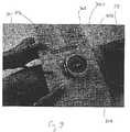
- FIG. 5is a partial sectional view of a pressure measuring device made in accordance with a fourth preferred embodiment as used with an inflatable blood pressure sleeve;
- FIG. 6is a side elevational view, partly in section, of a pressure measuring device made in accordance with a fifth preferred embodiment of the present invention.
- FIG. 7is an unassembled view of the pressure measuring device of FIG. 6;
- FIG. 8is a partially exploded view of the housing of the pressure measuring device of FIGS. 6 and 7;
- FIG. 9is a side elevational view, in section, of a gage housing made in accordance with a sixth embodiment of the present invention.
- FIG. 9Ais an enlarged view of the attachment of the peripheral bumper to the gage housing of FIG. 9;
- FIG. 10is a top perspective view of the gage housing of FIG. 9;
- FIG. 11is a side perspective view of a gage housing made in accordance with a seventh embodiment of the present invention.
- FIG. 12is a side elevational view, in section, of the gage housing of FIG. 11;
- FIGS. 12A and 12Bare enlarged partial sectioned views of a protective peripheral bumper as attached to the gage housing of FIG. 12;
- FIG. 13is a top perspective view of the gage housing of FIG. 12;
- FIG. 14is a bottom perspective view of the gage housing of FIG. 12 having a shock resistant feature made in accordance with another embodiment of the present invention.
- FIG. 15is a partially exploded view of a conventional blood pressure measuring apparatus
- FIGS. 16 and 17are side elevation views, partly in section, of conventional gage housings which have been configured for direct attachment to an inflatable blood pressure sleeve;
- FIG. 18is a top view of a blood pressure measuring apparatus in accordance with a preferred embodiment of the invention.
- FIG. 19is a perspective view of the inflatable sleeve of the apparatus of FIG. 18 as used with a patient.
- gagerefers to any movement mechanism disposed within a gage housing which does not include a gear or gear-like element.
- the primary embodiments referred to throughout the majority of the following discussionrefer to a gearless analog blood pressure measurement apparatus.
- Hoselessrefers to a direct connection between a gage housing and an inflatable sleeve of a pressure measuring apparatus without any intermediate hose or hoses there between.
- the device 10includes a substantially cylindrical gage housing 12 having an interior cavity 14 defined by a circumferential inner wall 16 , an open top end 18 , and a bottom end 20 .
- a viewing window or bubble 22made from glass, plastic, or other suitable transparent material is attached in a known manner to the open top end 18 of the gage housing 12 .
- the bottom end 20 of the gage housing 12has a diameter which inwardly tapers down to a narrow downwardly extending portion 24 having a bottom opening 26 serving as an inlet port for admitting a fluid.
- the diameter of the narrow extending portion 24is about one third of the diameter of the major portion of the housing 12 , though it will be apparent from the following discussion that this parameter can be suitably varied depending upon the application.
- the interior cavity 14 of the housing 12is sized for retaining a number of component parts, including a horizontally disposed support plate 28 .
- the support plate 28is a generally planar member having opposing top and bottom facing sides 30 , 32 , and a central through opening 34 .
- a press-fitted or otherwise suitably attached or integral sleeve 36 attached to the top facing side 30 of the support plate 28extends into the central through opening 34 of the support plate 28 and is used for retaining a movement mechanism 40 , described in greater detail below.
- the circumferential inner wall 16 of the housing 12further includes a reflexed portion 19 which is sized for supporting an outer edge 21 of the horizontal support plate 28 immediately there beneath and at a predetermined height within the housing 12 .
- the central through opening 34is shown as being substantially aligned with the bottom opening 26 of the housing 12 , but this particular alignment is not critical to the workings of the present invention and therefore can be varied.
- a diaphragm subassembly 42includes a flexible diaphragm 44 which is non-fixedly attached to the bottom facing side 32 of the horizontal support plate 28 .
- the diaphragm 44is substantially horizontally planar and includes a plurality of wave-like surfaces 49 .
- An outer edge 47 of the diaphragm 44is clamped by an O-ring 46 disposed on a circumferential ledge 45 extending upwardly from the bottom end 20 of the housing 12 .
- the O-ring 46not only supports the diaphragm 44 in place, but also provides a fluid tight sea for the bottom of the interior cavity 14 .
- the centermost portion of the horizontally planar diaphragm 44includes a downwardly extending section, herein after referred to as the pan 48 , which is soldered or otherwise fixed or even integral with the remainder of the diaphragm 44 .
- the pan 48is a hollow cylindrical section which extends into the downwardly extending portion 24 of the housing 12 when assembled and includes a cavity 50 having a width dimension that is substantially equal to that of the press-fitted sleeve 36 .
- a lower end 53 of the pan 48includes a interior contact surface 52 which is hardened.
- the movement mechanism 40includes an axially displace able shaft member 54 which is wholly enclosed within a tubular member 56 with the exception of protruding top and bottom ends 57 , 55 , respectively.
- a thin flexible ribbon-like spring member 70is fixedly attached at one end 61 adjacent a bottom end of the tubular member 56 and at an opposite remaining end 59 to the axially displace able shaft member 54 around which the ribbon spring member 70 is helically or spirally wound.
- the outer tubular member 56includes a set of external threads 73 extending over an upper portion of the length thereof which engage corresponding internal threads 75 provided in the press-fitted sleeve 36 .
- the ribbon spring member 70is preferably fabricated from beryllium copper, spring steel, or other similar material.
- the hollow tubular member 56includes an integral top cap portion 58 having a diameter which is larger than that of the remainder of the member, the cap portion having a shoulder which bears against a biasing spring 68 disposed within an annular recess 69 of the press-fitted sleeve 36 .
- the top cap portion 58 and the biasing spring 68are used to adjust the overall sensitivity of the movement mechanism 40 .
- the majority of the movement mechanism 40extends beneath the horizontal support plate 28 and into the cavity 50 defined in the pan 48 which is already positioned in the downwardly extending portion 24 of the housing 12 .
- the extending bottom end 55 of the shaft member 54is proximate to the hardened contact surface 52 .
- a dial face 63 having measuring indicia(not shown) is attached to the top facing side 30 of the horizontal support plate 28 through a center opening which is sized to fit over the press-fitted sleeve 36 .
- An O-ring 65 disposed in a slot 67 of the tubular sleeve 36engages an inner edge of the dial face 63 with an indicating member 62 being mounted to the protruding top end 57 of the shaft member 54 .
- a preferred lightweight indicating member useful in his designis described in U.S. Ser. No. 09/471,847, the entire contents of which are herein incorporated by reference.
- the ribbon spring member 70is caused to extend against the fixed end 61 of the tubular member 56 , causing the shaft member 54 to rotate about its linear axis.
- the rotation of the axially displace able shaft member 54therefore causes a corresponding circumferential movement of the indicating member 62 attached to the top end 57 of the shaft member 54 relative to the measuring indicia (not shown) on the dial face 63 .
- Zero adjustment of the above pressure measuring device 10is a relatively simple procedure, as compared with previously known devices.
- the viewing window 22is removed from the open top end 18 of the gage housing 12 .
- the engagement of the O-ring 65 against the inner edge of the dial face 63allows the dial face to be freely rotated in relation to the position of the indicating member 62 .
- Sensitivity adjustmentscan also be made at the top of the device 10 by rotating the top cap portion 58 against the biasing spring 68 within the annular recess 69 of the press-fitted sleeve 36 , so as to adjust the sensitivity of the ribbon spring member 70 for a given rotation.
- a similar mechanismis described in previously incorporated U.S. Pat. No. 6,168,566.
- either the dial face 63 A and/or the horizontal support plate 28 Acan be tapered suitably adjacent their center openings relative to a slot 80 provided in the tubular sleeve 36 A in order to allow the dial face to be rotated without requiring removal.
- the movement mechanism 40can include a zero adjustment feature as described in U.S. Pat. No. 5,966,829 and U.S. Pat. No. 6,168,566.
- FIG. 2merely illustrates a portion of the overall assembly in order to distinctly facilitate the above discussion.
- the deviceincludes a gage housing 12 having an interior cavity 14 sized for retaining a diaphragm assembly 42 which includes a diaphragm 44 having a series of wave-like surfaces 49 as well as a downwardly extending portion or pan 48 .
- the devicefurther includes a substantially horizontally disposed planar support plate 28 , the housing 12 further having a downwardly extending narrowed portion 24 .
- a movement mechanism 40is disposed through a central opening 34 defined in the horizontal support plate 28 such that the bottom end 55 of an axially displace able shaft 54 of the mechanism is disposed in proximity to a hardened contact surface 52 of the pan 48 of the diaphragm assembly 42 .
- the diaphragm 44in the meantime is attached, but sealed, to the bottom facing side 32 of the horizontal support plate 28 .
- Fluidsuch as air
- entering the gage housing 12 through a bottom opening 26causes deflection of the pan 48 of the diaphragm 44 against the axially displace able shaft 54 , thereby causing rotation of the shaft by means of an attached ribbon spring member 70 , according to the manner previously described.
- the deviceincludes a docking hub 82 provided on the exterior of narrow downwardly extending portion 24 of the housing 12 , the hub including a circumferential slot 114 which is sized for retaining an O-ring 118 or other similar sealing element.
- the docking hub 82can utilize pipe or other form of known threads (not shown).
- the docking hub 82provides adequate modification to allow the device to be attached to other existing pressure device housings having pressure sources, for example, those manufactured by Welch Allyn, Inc. of Skaneateles Falls, N.Y., among others.
- the position of the bottom opening 26 of the housing 12is not essential; that is, incoming fluid can enter the housing 12 from either a horizontally or otherwise disposed port, so long as the opening is beneath the seal which is provided by the O-ring 118 .
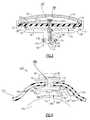
- a third embodiment of a housing 12 B made in accordance with the present inventionincludes a diaphragm 44 B, which unlike the preceding embodiments, is a substantially vertical member having an overall width dimension that is considerably narrower than those previously described. As a result, a horizontal support plate is not required as in the preceding which is fitted to the circumferential inner wall 16 of the housing 12 B.
- an outer edge 47 B of the diaphragm 44 Bis sealed using an O-ring 46 B or other sealing member which effectively clamps the outer edge to a shoulder of the a press-fitted sleeve 36 B.
- the movement mechanism 40is disposed essentially through a center opening in a press-fitted sleeve 36 B and threaded into engagement therewith. The majority of the movement mechanism 40 is disposed within the cavity defined by the essentially vertical diaphragm 44 B, the particular diaphragm of this embodiment having vertically disposed wave-like surfaces 49 B. Adjustments to control the sensitivity of the movement mechanism 40 using biasing spring 68 B are performed in the manner previously described.
- the housing of the instant embodimentdefines a very shallow profile for the upper portion of the gage housing 12 B.
- the bottom end 20 B of the gage housing 12 Bcan be used as a docking hub to secure the gage housing into other gage housings (not shown) either as a retrofitted or as a new assembly as previously described.
- this docking hubcan also permit direct hose-free connection between a gage housing and an inflatable blood pressure sleeve.
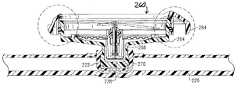
- a gage or instrument housing 140 formed in accordance with a fourth embodiment of the present inventionis herein described in combination with a blood pressure sleeve or cuff 142 .
- the instrument housing 140is used with a specific blood pressure cuff which is described in greater detail in U.S. Pat. No. 6,036,718, the contents of which are hereby incorporated in its entirety.
- the inflatable cuff 142is manufactured using a pair of sleeve portions 144 , 146 which are sealed together using a series of continuous RF (radio frequency) welds to form an integral bladder less structure having an inflatable inner volume 148 .
- the cuff 142is then wrapped as conventionally known about the arm 170 (partially shown) or other limb of a patient.
- the gage housing 140includes an upper housing portion 152 , a lower housing portion 154 , and a connecting intermediate portion 156 .
- the upper and lower housing portions 152 , 154are substantially cylindrical in cross section and have approximately the same dimensions while the intermediate portion 156 has a substantially smaller diameter that is considerably narrower than either adjoining section, thereby defining a configuration resembling a yo-yo.
- the intermediate portion 156has a diameter which is approximately one third the diameter of the remaining portions 152 , 154 , but it will be readily apparent that this parameter can be varied depending on the relative size of the movement mechanism used therein.
- Each of the above portions 152 , 154 , 156are interconnected and hollow, combining to form an interior cavity 158 .
- a horizontal support plate 165(shown in phantom) is positioned within the lower portion 154 of the housing 140 while a dial face 167 (also shown in phantom) is disposed in the upper portion 152 .
- a movement mechanism 171(also shown in phantom) which is similar structurally to those previously described, interconnects the dial face 167 and the support plate 165 and is located primarily in the intermediate portion 156 .
- a slot 162is cut into one of the sleeve portions 144 , 146 .
- the slot 162provides a button-like retainment for the lower portion 154 of the housing 140 as well as the intermediate portion 156 , with the upper portion 152 protruding from the exterior of the cuff 142 .
- a port 176is connected via a hose 178 to the inflatable inner volume 148 of the cuff 142 which is inflated by a pneumatic bulb (not shown) in a well known manner.
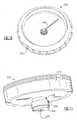
- the deviceoperates similarly to that previously described, except that a detachable stethoscope adapter 166 can also be attached to the bottom of the lower housing portion 154 , thereby forming an integral unit.
- the bottom of the lower portion 154includes an extending attachment portion 174 sized to engage a female connector 180 or other suitable means provided on the adapter 166 . All preceding known cuffs require separation between the cuff and the stethoscope. With the overall shallow profile of the above housing 140 , use of an adapter 166 permits an interconnection which is highly advantageous.
- the stethoscope adapter 166is a conical member which forms the bell of the stethoscope having connecting ear pieces (not shown) attached to a port 184 .
- the adapter 166is freely rotatable relative to the housing 140 , allowing examination by a patient or care giver to be performed equally well.
- the overall workings of stethoscopesare commonly known and do not form part of the inventive concepts described hereon.
- FIGS. 6-8there is shown a blood pressure measuring device made in accordance with a fifth embodiment of the present invention.
- This deviceincludes an RF welded blood pressure sleeve 142 similar to that described in the previously incorporated '718 patent including a pair of sleeve portions 144 , 146 which are sealed together to form an integral structure and define an inflatable inner volume 148 .
- the sleeve 142is sized to be wrapped around the arm or other limb of a patient (not shown) in a manner which is commonly known, and therefore requiring no further explanation.
- a socket 190is disposed and fixed within a slot which is provided on the exterior of one of the sleeve portions 144 , the socket being sized to receive a mating portion of an instrument or gage housing 194 .
- the instrument housing 194according to this embodiment is similar to those previously described including a narrowed bottom portion, but in which the bottom portion also includes a ball-shaped engagement or mating end 196 .
- the ball-shaped engagement end 196is fitted within the socket 190 of the sleeve in order to provide a direct fluid and sealed connection therewith, the gage housing 194 being free to pivot about the plane of the sleeve 142 as shown by reference numeral 198 .
- the engagement end 196includes an opening 200 which permits fluid communication with the interior of the sleeve 142 wherein fluid (air) can enter the interior of the gage housing 194 to cause corresponding movement of a diaphragm and a contained movement mechanism (not shown), in the manner previously described herein.
- the viewing window 22 of the housing 194includes an anti-reflective coating to reduce or substantially reduce glare, with the user (physician or care giver) or patient having the ability to either rotate the housing or to pivot same in order to effectively utilize the instrument and read the dial face.
- the gage housing 194can effectively be used in either a right or left armed patient measurement. A sleeve which further provides this ability with an attached gage housing is described in greater detail below.
- the devicefurther includes a rubberized ring-shaped guard or bumper 202 which is press-fitted into engagement about the outer periphery of the gage housing 194 , the bumper having a ridge 206 which extends a predetermined distance above the viewing window 22 .
- the bumper 202performs at least two functions; first, and though the present device is ultra lightweight, the bumper additionally absorbs shock or impact loads when the housing 194 is dropped. Second, the bumper 202 also prevents damage to the viewing window 22 .
- the mating or engagement end of the narrowed bottom portion of the instrument or gage housingneed not include a ball-shape for accommodation within the sleeve socket 190 . Examples are discussed below with reference to FIGS. 9-14.
- gage housingswhich include a pressure responsive member can be configured or retrofitted for direct engagement with a blood pressure sleeve without requiring hoses (hoseless) between the housing and the sleeve.
- An exampleis partially shown in FIG. 15, a gage housing 296 retaining a conventional movement mechanism 292 .
- the movement mechanism 292includes a threaded end 297 which extends through a bottom opening 299 of the housing 296 and is received into the mating threaded end of a port 300 of a tubular member 305 , the input end of which includes a pneumatic bulb 307 .
- the output end 309 of the tubular member 305receives a hose (not shown) which extends to a coupling of a blood pressure sleeve (not shown).
- gage housings 294 , 306which can be interconnected to a blood pressure sleeve 324 in a manner similar that previously described.
- Each of these conventional housings 294 , 306similar to those of FIG. 15, are less compact than those which have been expressly detailed, mainly because of the intricacy and sizing of the movement mechanism that is contained therein.
- Each of the gage housings 294 , 306do commonly contain a threaded engagement end or inlet port 298 , 310 , which permits fluid communication between the housing interior and the pneumatic bulb 307 , FIG. 15 .
- the bulb 307is attached using a hose (not shown) to the inlet port.
- any gage housing having an engagement or inlet end and including literally any form of movement mechanismcan be reconfigured according to the present invention for hoseless interconnection with an inflatable sleeve.
- the end of the threaded inlet port 298 , 310can be covered with an adapter or cap 302 which is sized for sealing engagement within a socket 320 provided in an inflatable blood pressure sleeve 324 .
- the cap 302 and the socket 320each include respective openings 304 , 308 , which as shown in FIGS. 16 and 17 upon attachment to the inflatable sleeve 324 , permits direct fluid communication between the interior 328 of the sleeve 324 and the interior of the housing 294 , 306 , the housing being preferably snap-fitted to the sleeve.
- the gage housing 210is used in connection with a blood pressure measuring device and includes an upper housing portion 212 which retains a movement mechanism 214 and a narrowed lower portion 218 having a mating or engagement end 220 which is sized to engage a generally cylindrical socket 222 formed in a sleeve portion of a bladderless blood pressure cuff or sleeve 226 .
- the mating end 220 of the narrowed lower portion 218is also generally cylindrical in cross section, the end similarly including an end opening 224 , shown in FIG. 11, which permits fluid communication with the interior of the blood pressure cuff 226 via a corresponding opening 228 also formed in the socket 222 , thereby forming a fluid inlet port.
- the upper housing portion 212 of the gage housing 210 and the contained movement mechanism 214are similar to those previously described. That is, the movement mechanism 214 includes a helically wound thin ribbon spring 240 which is attached at one end to an axially displaceable shaft member and at a second end to a tubular sleeve member in the manner described above.
- Changes in pressure of the cuff 226cause fluid to enter the narrowed lower housing portion 218 through the end opening 224 , affecting a contained diaphragm 246 and causing the axially displaceable shaft member to be translated upwardly, resulting in rotation of the shaft member against the biasing of the ribbon spring 240 and circumferential movement of an indicating member 248 , attached to a protruding top end of the shaft member, relative to a dial face.
- the mating end 220 of the narrowed lower housing portion 218further includes a circumferential channel or notch 250 , which is most clearly shown in FIG. 11 .
- the circumferential channel 250provides a discontinuous path for shock and impact loads and, therefore, effectively cushions the contents of the gage housing 210 including the movement mechanism 214 , from shock or impact loads such as when the housing 210 lands on the narrowed lower portion 218 .
- a rubberized peripheral guard or bumper member 232sized to fit over the exterior periphery of the upper housing portion 212 is press fitted into engagement therewith.
- the guard member 232is similar to that previously described above in that the entire periphery of the upper housing portion 212 is covered, the guard member including a stepped portion 234 , shown in FIG. 9A, which extends over the top of the upper housing portion, including the viewing window, and defines an air gap 236 along the outer circumferential edge thereof.
- the air gap 236provides a discontinuous path for any impact loads which can occur if the gage housing 210 lands awkwardly.
- FIGS. 12-14there is shown a gage housing 260 according to a seventh embodiment of the present invention.
- the gage housing 260also includes an upper housing portion 264 and a narrowed lower housing portion 268 having an engagement end 270 which mates with a socket 222 which is formed in blood pressure sleeve 226 .
- the upper housing portion 264according to this embodiment is defined by a substantially elliptical cylindrical cross section as opposed to the preceding embodiments in which the upper housing portions are substantially circular cylinders. It should be noted that other shapes or geometries could be contemplated.
- a circumferential channel 272 provided in the bottom surface 276 of the engagement end 270provides a similar function to the axial circumferential channel 250 , FIG. 11, with regard to shock or impact loads applied to the housing if dropped or otherwise acted upon.
- the engagement end 270similarly engages the socket 222 of the sleeve 226 , the gage housing 260 retaining a movement mechanism (not shown) as previously described.
- the engagement end 270includes an end opening 271 which permits hoseless fluid communication with the sleeve 226 , also as previously described, through a socket opening 228 which extends to the sleeve interior.
- a rubberized guard member 280is press fitted over the exterior periphery of the upper housing portion 264 , the guard member according to this embodiment including a radially extending portion 284 which when attached extends from the outer edge of the elliptically shaped upper housing portion 264 and similarly provides a cushioning air gap 286 which creates a discontinuity, in fact a buffer, which insulates the housing 260 from impact loads when the housing is dropped. Similar air gaps 288 are provided above the viewing window as defined in an axially extending portion 290 to provide additional protection against shock or impact loads.
- an O-ring 289is provided within the annular air gap 288 .
- Additional shock resistance between adjoining portions of the housing 264 and the interior wall surface of the guard memberinclude an annular rubberized shim 285 .
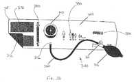
- a sleeve 344 for a blood pressure measuring apparatus 340is herein described.
- the sleeve 344itself is constructed from a pair of sleeve portions 368 , 372 made from a polyamide or other similar fluid impermeable material which are RF welded or bonded together and define an interior chamber.
- the interior chamber of the sleeve 344is inflated by means of a pneumatic bulb 356 which is tethered by tubing 360 to a barb or port 352 provided on a sleeve portion 368 , the barb having an opening which is in communication with the interior chamber of the sleeve.
- a check valve 364provided adjacent to the pneumatic bulb 356 permits depression thereof when the valve is opened.
- the sleeve 344includes hook and loop fastener portions (only one of which 376 being shown) on the outward facing sides of each of the sleeve portions 368 , 372 at opposite ends of the sleeve, thereby permitting the sleeve to be formed into a cylindrical shape and secured when wrapped about the limb of a patient 375 , as shown in FIG. 19 .
- Each hook and loop fastener portion 376is also preferably RF welded to a sleeve portion 368 , 372 .
- the facing side of the sleeve portion 372contacts the patient with the facing side of the sleeve portion 368 being exposed.
- each facing sidehas a different color to assist in attaching same to the patient.
- the sleeve 344is two-toned with the facing side of the sleeve portion 372 having a black colored finish and the facing side of the exposed sleeve portion 368 having a lighter colored finish.
- a socket or port(not shown) similar to those described above and shown for example in FIGS. 9 and 12 is also provided in the sleeve portion 368 , the socket being sized for receiving a gage housing 348 which is releasably snap-fitted in the manner previously described and defined.
- the gage housing 348when attached, can be rotated about its vertical axis, permitting easy visual access to either the care giver and/or the patient.
- the gage housing 348is identical to that previously shown and described in FIG. 9, the housing containing a bellows assembly as well as a gearless movement mechanism which operates in the manner described above to permit circumferential movement of an indicating member relative to a dial face when pressure changes within the interior chamber of the sleeve 344 cause movement to a movable surface of the bellows assembly.
- the gage housing 348also preferably includes the shock/impact resistant features previously described.
- An artery index marker 380is provided adjacent the hook and loop fastener portion 376 on the facing side of the sleeve portion 368 .
- This marker 380is used to align the sleeve with the brachial artery of the patient, the marker further including left and right limb indicators which are provided on respective lateral sides of the sleeve 344 .
- the markeris used to properly and circumferentially align the arm and the artery with the limb indicator pointing directly at the artery.
- the rotatability of the gage housing 348 within the sleeve 344permits the sleeve having the attached gage housing to be used when attached regardless of orientation.
- sets of indicia 384 , 388are also provided on the facing side of the sleeve portion 368 designating the size of sleeve being used; that is, whether the sleeve is an adult, child or neonatal cuff. An adult sleeve is shown in the present embodiment.
- the gage housing 348can be releasably attached in the manner described herein to any of the above noted sleeves, regardless of size.
Landscapes
- Health & Medical Sciences (AREA)
- Life Sciences & Earth Sciences (AREA)
- Physics & Mathematics (AREA)
- Cardiology (AREA)
- General Physics & Mathematics (AREA)
- Vascular Medicine (AREA)
- Biomedical Technology (AREA)
- Molecular Biology (AREA)
- Pathology (AREA)
- Engineering & Computer Science (AREA)
- Physiology (AREA)
- Heart & Thoracic Surgery (AREA)
- Medical Informatics (AREA)
- Biophysics (AREA)
- Surgery (AREA)
- Animal Behavior & Ethology (AREA)
- General Health & Medical Sciences (AREA)
- Public Health (AREA)
- Veterinary Medicine (AREA)
- Ophthalmology & Optometry (AREA)
- Measuring Pulse, Heart Rate, Blood Pressure Or Blood Flow (AREA)
- Measuring Fluid Pressure (AREA)
Abstract
Description
Claims (13)
Priority Applications (1)
| Application Number | Priority Date | Filing Date | Title |
|---|---|---|---|
| US10/608,202US6796186B2 (en) | 2000-09-25 | 2003-06-27 | Blood pressure measuring device with directly couplable measurement mechanism |
Applications Claiming Priority (3)
| Application Number | Priority Date | Filing Date | Title |
|---|---|---|---|
| US09/669,474US6422086B1 (en) | 2000-09-25 | 2000-09-25 | Low profile pressure measuring device |
| US09/929,501US6615666B1 (en) | 2000-09-25 | 2001-08-14 | Pressure measuring device |
| US10/608,202US6796186B2 (en) | 2000-09-25 | 2003-06-27 | Blood pressure measuring device with directly couplable measurement mechanism |
Related Parent Applications (1)
| Application Number | Title | Priority Date | Filing Date |
|---|---|---|---|
| US09/929,501DivisionUS6615666B1 (en) | 2000-09-25 | 2001-08-14 | Pressure measuring device |
Publications (2)
| Publication Number | Publication Date |
|---|---|
| US20040083816A1 US20040083816A1 (en) | 2004-05-06 |
| US6796186B2true US6796186B2 (en) | 2004-09-28 |
Family
ID=24686440
Family Applications (5)
| Application Number | Title | Priority Date | Filing Date |
|---|---|---|---|
| US09/669,474Expired - LifetimeUS6422086B1 (en) | 2000-09-25 | 2000-09-25 | Low profile pressure measuring device |
| US09/929,856Expired - LifetimeUS6578428B1 (en) | 2000-09-25 | 2001-08-14 | Blood pressure measuring apparatus |
| US09/929,501Expired - LifetimeUS6615666B1 (en) | 2000-09-25 | 2001-08-14 | Pressure measuring device |
| US09/929,847Expired - LifetimeUS6481291B1 (en) | 2000-09-25 | 2001-08-14 | Pressure measuring device |
| US10/608,202Expired - LifetimeUS6796186B2 (en) | 2000-09-25 | 2003-06-27 | Blood pressure measuring device with directly couplable measurement mechanism |
Family Applications Before (4)
| Application Number | Title | Priority Date | Filing Date |
|---|---|---|---|
| US09/669,474Expired - LifetimeUS6422086B1 (en) | 2000-09-25 | 2000-09-25 | Low profile pressure measuring device |
| US09/929,856Expired - LifetimeUS6578428B1 (en) | 2000-09-25 | 2001-08-14 | Blood pressure measuring apparatus |
| US09/929,501Expired - LifetimeUS6615666B1 (en) | 2000-09-25 | 2001-08-14 | Pressure measuring device |
| US09/929,847Expired - LifetimeUS6481291B1 (en) | 2000-09-25 | 2001-08-14 | Pressure measuring device |
Country Status (3)
| Country | Link |
|---|---|
| US (5) | US6422086B1 (en) |
| EP (1) | EP1992281B1 (en) |
| DE (1) | DE60143460D1 (en) |
Cited By (33)
| Publication number | Priority date | Publication date | Assignee | Title |
|---|---|---|---|---|
| US20060207334A1 (en)* | 2005-03-16 | 2006-09-21 | Welch Allyn, Inc. | Shock resistant blood pressure measuring apparatus |
| US20060293600A1 (en)* | 2000-09-25 | 2006-12-28 | Welch Allyn, Inc. | Blood pressure measuring apparatus |
| US20080194976A1 (en)* | 2007-02-12 | 2008-08-14 | Welch Allyn, Inc. | Diaphragm assembly for blood pressure measuring apparatus |
| USD643536S1 (en) | 2009-05-19 | 2011-08-16 | Welch Allyn, Inc. | Blood-pressure cuff |
| EP2462865A2 (en) | 2005-09-19 | 2012-06-13 | Welch Allyn, Inc. | Blood pressure measuring apparatus |
| US8652057B2 (en) | 2009-05-19 | 2014-02-18 | Welch Allyn, Inc. | Recyclable or biodegradable blood pressure cuff |
| US8827317B2 (en) | 2010-05-07 | 2014-09-09 | Welch Allyn, Inc. | Medical device adaptor |
| US9220422B2 (en) | 2012-11-19 | 2015-12-29 | Welch Allyn, Inc. | Blood pressure sleeve |
| USD757259S1 (en) | 2012-04-05 | 2016-05-24 | Medline Industries, Inc. | Female portion of a connector |
| USD788312S1 (en) | 2012-02-09 | 2017-05-30 | Masimo Corporation | Wireless patient monitoring device |
| US9788735B2 (en) | 2002-03-25 | 2017-10-17 | Masimo Corporation | Body worn mobile medical patient monitor |
| US9847002B2 (en) | 2009-12-21 | 2017-12-19 | Masimo Corporation | Modular patient monitor |
| US9913617B2 (en) | 2011-10-13 | 2018-03-13 | Masimo Corporation | Medical monitoring hub |
| US9943269B2 (en) | 2011-10-13 | 2018-04-17 | Masimo Corporation | System for displaying medical monitoring data |
| KR101918415B1 (en) | 2017-10-25 | 2018-11-13 | 주식회사 현대케피코 | Oil complex ssensor with shock wave reduction filter |
| US10226187B2 (en) | 2015-08-31 | 2019-03-12 | Masimo Corporation | Patient-worn wireless physiological sensor |
| US10359139B2 (en) | 2012-04-05 | 2019-07-23 | Medline Industries, Inc. | Connector |
| US10413199B2 (en) | 2017-11-02 | 2019-09-17 | Welch Allyn, Inc. | Connectors for medical equipment |
| US10617302B2 (en) | 2016-07-07 | 2020-04-14 | Masimo Corporation | Wearable pulse oximeter and respiration monitor |
| US10825568B2 (en) | 2013-10-11 | 2020-11-03 | Masimo Corporation | Alarm notification system |
| US10833983B2 (en) | 2012-09-20 | 2020-11-10 | Masimo Corporation | Intelligent medical escalation process |
| US10912524B2 (en) | 2006-09-22 | 2021-02-09 | Masimo Corporation | Modular patient monitor |
| US11076777B2 (en) | 2016-10-13 | 2021-08-03 | Masimo Corporation | Systems and methods for monitoring orientation to reduce pressure ulcer formation |
| US11109818B2 (en) | 2018-04-19 | 2021-09-07 | Masimo Corporation | Mobile patient alarm display |
| USD974193S1 (en) | 2020-07-27 | 2023-01-03 | Masimo Corporation | Wearable temperature measurement device |
| USD980091S1 (en) | 2020-07-27 | 2023-03-07 | Masimo Corporation | Wearable temperature measurement device |
| USD1000975S1 (en) | 2021-09-22 | 2023-10-10 | Masimo Corporation | Wearable temperature measurement device |
| US11963736B2 (en) | 2009-07-20 | 2024-04-23 | Masimo Corporation | Wireless patient monitoring system |
| US11974833B2 (en) | 2020-03-20 | 2024-05-07 | Masimo Corporation | Wearable device for noninvasive body temperature measurement |
| USD1048908S1 (en) | 2022-10-04 | 2024-10-29 | Masimo Corporation | Wearable sensor |
| US12257022B2 (en) | 2018-10-12 | 2025-03-25 | Masimo Corporation | System for transmission of sensor data using dual communication protocol |
| USD1072837S1 (en) | 2020-10-27 | 2025-04-29 | Masimo Corporation | Display screen or portion thereof with graphical user interface |
| US12440128B2 (en) | 2022-12-23 | 2025-10-14 | Masimo Corporation | Wrist and finger worn pulse oximetry system |
Families Citing this family (21)
| Publication number | Priority date | Publication date | Assignee | Title |
|---|---|---|---|---|
| US7722542B2 (en) | 2000-09-25 | 2010-05-25 | Welch Allyn, Inc. | Blood pressure measuring apparatus |
| US6422086B1 (en)* | 2000-09-25 | 2002-07-23 | Welch Allyn, Inc. | Low profile pressure measuring device |
| US20020133794A1 (en)* | 2001-02-24 | 2002-09-19 | Ruban Kanapathippillai | Method and apparatus for integrated circuit debugging |
| US6746406B2 (en)* | 2001-12-19 | 2004-06-08 | Welch Allyn, Inc. | Blood pressure measuring apparatus |
| DE10303906A1 (en)* | 2003-01-31 | 2004-08-12 | Erka Kallmeyer Medizintechnik Gmbh & Co.Kg | Blood Pressure Monitor |
| US20050101843A1 (en)* | 2003-11-06 | 2005-05-12 | Welch Allyn, Inc. | Wireless disposable physiological sensor |
| US8190236B2 (en)* | 2005-01-24 | 2012-05-29 | Prince Martin R | Tourniquet for magnetic resonance angiography, and method of using same |
| US7670296B2 (en) | 2006-12-11 | 2010-03-02 | Welch Allyn, Inc. | Multi-purpose connector for blood pressure measurement equipment |
| JP2010538711A (en)* | 2007-09-13 | 2010-12-16 | ルドルフ リースター ゲゼルシャフト ミット ベシュレンクテル ハフツング | Pressure measuring device, especially blood pressure measuring device |
| US20090318818A1 (en)* | 2008-06-20 | 2009-12-24 | Welch Allyn, Inc. | Blood pressure monitoring system |
| DE102008049152A1 (en)* | 2008-09-26 | 2010-04-01 | Watts Instrumentation Gmbh | Rotatable instrument housing |
| CN102341684B (en)* | 2009-03-06 | 2014-11-26 | 德怀尔仪器公司 | Pressure gage with magnetically coupled diaphragm |
| US20100298724A1 (en)* | 2009-05-19 | 2010-11-25 | Welch Allyn, Inc. | Recyclable or biodegradable blood pressure cuff |
| EP2895835A1 (en)* | 2012-09-17 | 2015-07-22 | AVOX Systems Inc. | Pressure gauge for possible use in an aircraft |
| US9021883B2 (en)* | 2013-04-03 | 2015-05-05 | Ru-Wen Wang | Pressure gauge |
| US9955978B2 (en) | 2013-10-25 | 2018-05-01 | Medtronic Vascular, Inc. | Tissue compression device with multi-chamber bladder |
| US10758130B2 (en) | 2014-03-31 | 2020-09-01 | Welch Allyn, Inc. | Single site vitals |
| CN104540076B (en)* | 2014-11-20 | 2018-09-07 | 歌尔股份有限公司 | Loud speaker module |
| US10092194B2 (en)* | 2016-01-06 | 2018-10-09 | Care 2 Innovations, Inc. | Illuminated blood pressure cuff |
| CN114762593B (en)* | 2021-01-15 | 2025-07-01 | 欧姆龙健康医疗事业株式会社 | Blood pressure measuring device |
| CN113865774B (en)* | 2021-09-18 | 2024-07-19 | 苏州森斯缔夫传感科技有限公司 | Pressure sensor and manufacturing method thereof |
Citations (26)
| Publication number | Priority date | Publication date | Assignee | Title |
|---|---|---|---|---|
| US1106341A (en) | 1913-10-02 | 1914-08-04 | Bristol Company | Measuring instrument. |
| US1328876A (en) | 1918-12-24 | 1920-01-27 | Hill Alfred Nilsson | Measuring instrument |
| US1377032A (en) | 1918-12-23 | 1921-05-03 | Henry Hughes And Son Ltd | Aneroid barometer |
| DE591564C (en) | 1931-04-08 | 1934-01-23 | Elektro Technik G M B H | Device for producing fire-extinguishing foam |
| US2087494A (en) | 1933-12-19 | 1937-07-20 | Mason Neilan Regulator Company | Pressure differential indicator |
| US2341137A (en) | 1943-02-06 | 1944-02-08 | Milton H Damron | Compact sphygmomanometer |
| US2564669A (en) | 1945-11-13 | 1951-08-21 | James M Brady | Pressure measuring device |
| US2636394A (en) | 1948-03-19 | 1953-04-28 | Frederick C Melchior | Instrument actuating mechanism |
| US3797315A (en) | 1972-07-06 | 1974-03-19 | W Halpern | Remote indicating adjustable angle instrument |
| US3805618A (en) | 1972-08-11 | 1974-04-23 | Springfield Instr Co Inc | Pressure-responsive instrument |
| US3874242A (en) | 1972-08-11 | 1975-04-01 | Springfield Instr Company Inc | Pressure-responsive instrument |
| US4036061A (en) | 1975-06-17 | 1977-07-19 | Blasius Speidel | Blood pressure indicator gauge |
| US4040298A (en) | 1976-04-08 | 1977-08-09 | Lee Char Shin | Gearless pressure or temperature gauge |
| US4255970A (en) | 1978-12-13 | 1981-03-17 | Pottelberg Gaston C Van | Barometer mechanism |
| US4543824A (en) | 1983-04-26 | 1985-10-01 | Dostmann Gmbh & Co. Kg | Barometer |
| FR2592297A1 (en) | 1985-12-27 | 1987-07-03 | Spengler Ets E | Improvements to sphygmomanometers |
| US4685336A (en) | 1984-02-01 | 1987-08-11 | Lee Wang Industry Ltd. | Pressure gauge |
| US5181422A (en) | 1991-07-30 | 1993-01-26 | Dresser Industries, Inc. | Diaphragm type fluid pressure gauge |
| EP0705563A1 (en) | 1994-10-07 | 1996-04-10 | Omron Corporation | A blood pressure monitor |
| US5753821A (en) | 1997-01-02 | 1998-05-19 | Chin Ray Industrial Co., Ltd. | Single diaphragm pressure gauge with uniform thickness gauge frame |
| US5966829A (en) | 1997-11-18 | 1999-10-19 | Welch Allyn, Inc. | Mechanism for measuring device |
| WO2000022983A1 (en) | 1998-10-16 | 2000-04-27 | Medwave, Inc. | Non-invasive blood pressure sensor with motion artifact reduction |
| WO2000040941A1 (en) | 1999-01-07 | 2000-07-13 | Welch Allyn, Inc. | Pressure change measuring device |
| US6168566B1 (en) | 1998-10-14 | 2001-01-02 | Welch Allyn, Inc. | Pressure sensing device |
| US6213953B1 (en)* | 1999-12-27 | 2001-04-10 | American Medical Screening Ltd. | Blood pressure cuff |
| US6615666B1 (en)* | 2000-09-25 | 2003-09-09 | Welch Allyn, Inc. | Pressure measuring device |
Family Cites Families (16)
| Publication number | Priority date | Publication date | Assignee | Title |
|---|---|---|---|---|
| DE7120141U (en)* | 1971-02-01 | 1972-11-02 | Siemens Ag | BLOOD PRESSURE CUFF |
| SU895405A1 (en)* | 1979-07-05 | 1982-01-07 | Vnii Ispytatel Med Tech | Method and device for determining arterial pressure |
| US5025792A (en)* | 1985-09-26 | 1991-06-25 | The Hon Group | Continuous cutaneous blood pressure measuring apparatus and method |
| US4727885A (en)* | 1986-12-24 | 1988-03-01 | Spacelabs, Inc. | Self applied blood pressure cuff |
| US4802370A (en)* | 1986-12-29 | 1989-02-07 | Halliburton Company | Transducer and sensor apparatus and method |
| JP2669858B2 (en)* | 1988-07-26 | 1997-10-29 | 松下電工株式会社 | Wrist sphygmomanometer |
| DE3829456A1 (en)* | 1988-08-31 | 1990-03-01 | Nicolay Gmbh | METHOD AND DEVICE FOR NON-INVASIVELY EXAMINING THE BLOOD CIRCUIT OF A LIVING ORGANISM |
| US4920971A (en)* | 1988-12-09 | 1990-05-01 | Blessinger Martin W | Pneumatic vein inflation device |
| AU669172B2 (en)* | 1992-07-21 | 1996-05-30 | Critikon, Inc. | Interchangeable pneumatic connector for blood pressure monitors |
| US5320169A (en)* | 1992-12-14 | 1994-06-14 | Panex Corporation | Gauge carrier |
| US5396894A (en)* | 1993-09-07 | 1995-03-14 | Eide; Mark E. M. | Disposable pressure cuff for a blood pressure monitor |
| ATE169402T1 (en)* | 1993-10-13 | 1998-08-15 | Kk Holding Ag | THERMO-COMPENSATED PRESSURE TRANSDUCER MEMBRANE STRUCTURE |
| US5400787A (en)* | 1993-11-24 | 1995-03-28 | Magna-Lab, Inc. | Inflatable magnetic resonance imaging sensing coil assembly positioning and retaining device and method for using the same |
| US5424598A (en)* | 1994-01-18 | 1995-06-13 | Corbett; James P. | Crystal force and pressure transducers |
| US5505207A (en)* | 1994-01-28 | 1996-04-09 | Critikon, Inc. | Character distinguishing sized blood pressure cuff system |
| US6036718A (en) | 1998-07-02 | 2000-03-14 | Welch Allyn, Inc. | Bladderless blood pressure cuff |
- 2000
- 2000-09-25USUS09/669,474patent/US6422086B1/ennot_activeExpired - Lifetime
- 2001
- 2001-08-14USUS09/929,856patent/US6578428B1/ennot_activeExpired - Lifetime
- 2001-08-14USUS09/929,501patent/US6615666B1/ennot_activeExpired - Lifetime
- 2001-08-14USUS09/929,847patent/US6481291B1/ennot_activeExpired - Lifetime
- 2001-09-12DEDE60143460Tpatent/DE60143460D1/ennot_activeExpired - Lifetime
- 2001-09-12EPEP08015424Apatent/EP1992281B1/ennot_activeExpired - Lifetime
- 2003
- 2003-06-27USUS10/608,202patent/US6796186B2/ennot_activeExpired - Lifetime
Patent Citations (28)
| Publication number | Priority date | Publication date | Assignee | Title |
|---|---|---|---|---|
| US1106341A (en) | 1913-10-02 | 1914-08-04 | Bristol Company | Measuring instrument. |
| US1377032A (en) | 1918-12-23 | 1921-05-03 | Henry Hughes And Son Ltd | Aneroid barometer |
| US1328876A (en) | 1918-12-24 | 1920-01-27 | Hill Alfred Nilsson | Measuring instrument |
| DE591564C (en) | 1931-04-08 | 1934-01-23 | Elektro Technik G M B H | Device for producing fire-extinguishing foam |
| US2087494A (en) | 1933-12-19 | 1937-07-20 | Mason Neilan Regulator Company | Pressure differential indicator |
| US2341137A (en) | 1943-02-06 | 1944-02-08 | Milton H Damron | Compact sphygmomanometer |
| US2564669A (en) | 1945-11-13 | 1951-08-21 | James M Brady | Pressure measuring device |
| US2636394A (en) | 1948-03-19 | 1953-04-28 | Frederick C Melchior | Instrument actuating mechanism |
| US3797315A (en) | 1972-07-06 | 1974-03-19 | W Halpern | Remote indicating adjustable angle instrument |
| US3805618A (en) | 1972-08-11 | 1974-04-23 | Springfield Instr Co Inc | Pressure-responsive instrument |
| US3874242A (en) | 1972-08-11 | 1975-04-01 | Springfield Instr Company Inc | Pressure-responsive instrument |
| US4036061A (en) | 1975-06-17 | 1977-07-19 | Blasius Speidel | Blood pressure indicator gauge |
| US4040298A (en) | 1976-04-08 | 1977-08-09 | Lee Char Shin | Gearless pressure or temperature gauge |
| US4255970A (en) | 1978-12-13 | 1981-03-17 | Pottelberg Gaston C Van | Barometer mechanism |
| US4543824A (en) | 1983-04-26 | 1985-10-01 | Dostmann Gmbh & Co. Kg | Barometer |
| US4685336A (en) | 1984-02-01 | 1987-08-11 | Lee Wang Industry Ltd. | Pressure gauge |
| FR2592297A1 (en) | 1985-12-27 | 1987-07-03 | Spengler Ets E | Improvements to sphygmomanometers |
| US5181422A (en) | 1991-07-30 | 1993-01-26 | Dresser Industries, Inc. | Diaphragm type fluid pressure gauge |
| EP0705563A1 (en) | 1994-10-07 | 1996-04-10 | Omron Corporation | A blood pressure monitor |
| US5753821A (en) | 1997-01-02 | 1998-05-19 | Chin Ray Industrial Co., Ltd. | Single diaphragm pressure gauge with uniform thickness gauge frame |
| US5966829A (en) | 1997-11-18 | 1999-10-19 | Welch Allyn, Inc. | Mechanism for measuring device |
| US6234972B1 (en)* | 1997-11-18 | 2001-05-22 | Welch Allyn, Inc. | Mechanism for measuring device |
| US6168566B1 (en) | 1998-10-14 | 2001-01-02 | Welch Allyn, Inc. | Pressure sensing device |
| WO2000022983A1 (en) | 1998-10-16 | 2000-04-27 | Medwave, Inc. | Non-invasive blood pressure sensor with motion artifact reduction |
| US6120458A (en) | 1999-01-07 | 2000-09-19 | Welch Allyn, Inc. | Low profile pressure measure device |
| WO2000040941A1 (en) | 1999-01-07 | 2000-07-13 | Welch Allyn, Inc. | Pressure change measuring device |
| US6213953B1 (en)* | 1999-12-27 | 2001-04-10 | American Medical Screening Ltd. | Blood pressure cuff |
| US6615666B1 (en)* | 2000-09-25 | 2003-09-09 | Welch Allyn, Inc. | Pressure measuring device |
Cited By (85)
| Publication number | Priority date | Publication date | Assignee | Title |
|---|---|---|---|---|
| US8535233B2 (en) | 2000-09-25 | 2013-09-17 | Welch Allyn, Inc. | Blood pressure measuring apparatus |
| US20060293600A1 (en)* | 2000-09-25 | 2006-12-28 | Welch Allyn, Inc. | Blood pressure measuring apparatus |
| US9072435B2 (en) | 2000-09-25 | 2015-07-07 | Welch Allyn, Inc. | Blood pressure measuring apparatus |
| US10335033B2 (en) | 2002-03-25 | 2019-07-02 | Masimo Corporation | Physiological measurement device |
| US9795300B2 (en) | 2002-03-25 | 2017-10-24 | Masimo Corporation | Wearable portable patient monitor |
| US10213108B2 (en) | 2002-03-25 | 2019-02-26 | Masimo Corporation | Arm mountable portable patient monitor |
| US9788735B2 (en) | 2002-03-25 | 2017-10-17 | Masimo Corporation | Body worn mobile medical patient monitor |
| US10219706B2 (en) | 2002-03-25 | 2019-03-05 | Masimo Corporation | Physiological measurement device |
| US11484205B2 (en) | 2002-03-25 | 2022-11-01 | Masimo Corporation | Physiological measurement device |
| US9872623B2 (en) | 2002-03-25 | 2018-01-23 | Masimo Corporation | Arm mountable portable patient monitor |
| US10869602B2 (en) | 2002-03-25 | 2020-12-22 | Masimo Corporation | Physiological measurement communications adapter |
| US20060207334A1 (en)* | 2005-03-16 | 2006-09-21 | Welch Allyn, Inc. | Shock resistant blood pressure measuring apparatus |
| US7234356B2 (en) | 2005-03-16 | 2007-06-26 | Welch Allyn, Inc. | Shock resistant blood pressure measuring apparatus |
| EP2462865A2 (en) | 2005-09-19 | 2012-06-13 | Welch Allyn, Inc. | Blood pressure measuring apparatus |
| US10912524B2 (en) | 2006-09-22 | 2021-02-09 | Masimo Corporation | Modular patient monitor |
| US20080194976A1 (en)* | 2007-02-12 | 2008-08-14 | Welch Allyn, Inc. | Diaphragm assembly for blood pressure measuring apparatus |
| US10231630B2 (en) | 2009-05-19 | 2019-03-19 | Welch Allyn, Inc. | Recyclable or biodegradable blood pressure cuff |
| US12268483B2 (en) | 2009-05-19 | 2025-04-08 | Welch Allyn, Inc. | Recyclable or biodegradable blood pressure cuff |
| US11350834B2 (en) | 2009-05-19 | 2022-06-07 | Welch Allyn, Inc. | Recyclable or biodegradable blood pressure cuff |
| US8652057B2 (en) | 2009-05-19 | 2014-02-18 | Welch Allyn, Inc. | Recyclable or biodegradable blood pressure cuff |
| USD643536S1 (en) | 2009-05-19 | 2011-08-16 | Welch Allyn, Inc. | Blood-pressure cuff |
| US11963736B2 (en) | 2009-07-20 | 2024-04-23 | Masimo Corporation | Wireless patient monitoring system |
| US11900775B2 (en) | 2009-12-21 | 2024-02-13 | Masimo Corporation | Modular patient monitor |
| US10943450B2 (en) | 2009-12-21 | 2021-03-09 | Masimo Corporation | Modular patient monitor |
| US10354504B2 (en) | 2009-12-21 | 2019-07-16 | Masimo Corporation | Modular patient monitor |
| US9847002B2 (en) | 2009-12-21 | 2017-12-19 | Masimo Corporation | Modular patient monitor |
| US8827317B2 (en) | 2010-05-07 | 2014-09-09 | Welch Allyn, Inc. | Medical device adaptor |
| US11786183B2 (en) | 2011-10-13 | 2023-10-17 | Masimo Corporation | Medical monitoring hub |
| US9993207B2 (en) | 2011-10-13 | 2018-06-12 | Masimo Corporation | Medical monitoring hub |
| US12329548B2 (en) | 2011-10-13 | 2025-06-17 | Masimo Corporation | Medical monitoring hub |
| US12402843B2 (en) | 2011-10-13 | 2025-09-02 | Masimo Corporation | System for displaying medical monitoring data |
| US11241199B2 (en) | 2011-10-13 | 2022-02-08 | Masimo Corporation | System for displaying medical monitoring data |
| US11179114B2 (en) | 2011-10-13 | 2021-11-23 | Masimo Corporation | Medical monitoring hub |
| US10512436B2 (en) | 2011-10-13 | 2019-12-24 | Masimo Corporation | System for displaying medical monitoring data |
| US9913617B2 (en) | 2011-10-13 | 2018-03-13 | Masimo Corporation | Medical monitoring hub |
| US10925550B2 (en) | 2011-10-13 | 2021-02-23 | Masimo Corporation | Medical monitoring hub |
| US9943269B2 (en) | 2011-10-13 | 2018-04-17 | Masimo Corporation | System for displaying medical monitoring data |
| US10188296B2 (en) | 2012-02-09 | 2019-01-29 | Masimo Corporation | Wireless patient monitoring device |
| US11083397B2 (en) | 2012-02-09 | 2021-08-10 | Masimo Corporation | Wireless patient monitoring device |
| US11918353B2 (en) | 2012-02-09 | 2024-03-05 | Masimo Corporation | Wireless patient monitoring device |
| US10149616B2 (en) | 2012-02-09 | 2018-12-11 | Masimo Corporation | Wireless patient monitoring device |
| US12109022B2 (en) | 2012-02-09 | 2024-10-08 | Masimo Corporation | Wireless patient monitoring device |
| USD788312S1 (en) | 2012-02-09 | 2017-05-30 | Masimo Corporation | Wireless patient monitoring device |
| USD757259S1 (en) | 2012-04-05 | 2016-05-24 | Medline Industries, Inc. | Female portion of a connector |
| US10359139B2 (en) | 2012-04-05 | 2019-07-23 | Medline Industries, Inc. | Connector |
| US11887728B2 (en) | 2012-09-20 | 2024-01-30 | Masimo Corporation | Intelligent medical escalation process |
| US10833983B2 (en) | 2012-09-20 | 2020-11-10 | Masimo Corporation | Intelligent medical escalation process |
| US9220422B2 (en) | 2012-11-19 | 2015-12-29 | Welch Allyn, Inc. | Blood pressure sleeve |
| US12230396B2 (en) | 2013-10-11 | 2025-02-18 | Masimo Corporation | Alarm notification system |
| US11699526B2 (en) | 2013-10-11 | 2023-07-11 | Masimo Corporation | Alarm notification system |
| US12009098B2 (en) | 2013-10-11 | 2024-06-11 | Masimo Corporation | Alarm notification system |
| US10832818B2 (en) | 2013-10-11 | 2020-11-10 | Masimo Corporation | Alarm notification system |
| US11488711B2 (en) | 2013-10-11 | 2022-11-01 | Masimo Corporation | Alarm notification system |
| US10825568B2 (en) | 2013-10-11 | 2020-11-03 | Masimo Corporation | Alarm notification system |
| US10226187B2 (en) | 2015-08-31 | 2019-03-12 | Masimo Corporation | Patient-worn wireless physiological sensor |
| US10383527B2 (en) | 2015-08-31 | 2019-08-20 | Masimo Corporation | Wireless patient monitoring systems and methods |
| US10736518B2 (en) | 2015-08-31 | 2020-08-11 | Masimo Corporation | Systems and methods to monitor repositioning of a patient |
| US10448844B2 (en) | 2015-08-31 | 2019-10-22 | Masimo Corporation | Systems and methods for patient fall detection |
| US11576582B2 (en) | 2015-08-31 | 2023-02-14 | Masimo Corporation | Patient-worn wireless physiological sensor |
| US11089963B2 (en) | 2015-08-31 | 2021-08-17 | Masimo Corporation | Systems and methods for patient fall detection |
| US12133717B2 (en) | 2015-08-31 | 2024-11-05 | Masimo Corporation | Systems and methods for patient fall detection |
| US12150739B2 (en) | 2015-08-31 | 2024-11-26 | Masimo Corporation | Systems and methods for patient fall detection |
| US11202571B2 (en) | 2016-07-07 | 2021-12-21 | Masimo Corporation | Wearable pulse oximeter and respiration monitor |
| US10617302B2 (en) | 2016-07-07 | 2020-04-14 | Masimo Corporation | Wearable pulse oximeter and respiration monitor |
| US12070293B2 (en) | 2016-07-07 | 2024-08-27 | Masimo Corporation | Wearable pulse oximeter and respiration monitor |
| US11076777B2 (en) | 2016-10-13 | 2021-08-03 | Masimo Corporation | Systems and methods for monitoring orientation to reduce pressure ulcer formation |
| KR101918415B1 (en) | 2017-10-25 | 2018-11-13 | 주식회사 현대케피코 | Oil complex ssensor with shock wave reduction filter |
| US10820812B2 (en) | 2017-11-02 | 2020-11-03 | Welch Allyn, Inc. | Connectors for medical equipment |
| US11857295B2 (en) | 2017-11-02 | 2024-01-02 | Welch Allyn, Inc. | Connectors for medical equipment |
| US10413199B2 (en) | 2017-11-02 | 2019-09-17 | Welch Allyn, Inc. | Connectors for medical equipment |
| US11844634B2 (en) | 2018-04-19 | 2023-12-19 | Masimo Corporation | Mobile patient alarm display |
| US11109818B2 (en) | 2018-04-19 | 2021-09-07 | Masimo Corporation | Mobile patient alarm display |
| US12193849B2 (en) | 2018-04-19 | 2025-01-14 | Masimo Corporation | Mobile patient alarm display |
| US12257022B2 (en) | 2018-10-12 | 2025-03-25 | Masimo Corporation | System for transmission of sensor data using dual communication protocol |
| US11974833B2 (en) | 2020-03-20 | 2024-05-07 | Masimo Corporation | Wearable device for noninvasive body temperature measurement |
| US12364403B2 (en) | 2020-03-20 | 2025-07-22 | Masimo Corporation | Wearable device for noninvasive body temperature measurement |
| USD1022729S1 (en) | 2020-07-27 | 2024-04-16 | Masimo Corporation | Wearable temperature measurement device |
| USD980091S1 (en) | 2020-07-27 | 2023-03-07 | Masimo Corporation | Wearable temperature measurement device |
| USD974193S1 (en) | 2020-07-27 | 2023-01-03 | Masimo Corporation | Wearable temperature measurement device |
| USD1072837S1 (en) | 2020-10-27 | 2025-04-29 | Masimo Corporation | Display screen or portion thereof with graphical user interface |
| US12440171B2 (en) | 2021-01-05 | 2025-10-14 | Masimo Corporation | Modular patient monitor |
| USD1000975S1 (en) | 2021-09-22 | 2023-10-10 | Masimo Corporation | Wearable temperature measurement device |
| USD1050910S1 (en) | 2021-09-22 | 2024-11-12 | Masimo Corporation | Portion of a wearable temperature measurement device |
| USD1048908S1 (en) | 2022-10-04 | 2024-10-29 | Masimo Corporation | Wearable sensor |
| US12440128B2 (en) | 2022-12-23 | 2025-10-14 | Masimo Corporation | Wrist and finger worn pulse oximetry system |
Also Published As
| Publication number | Publication date |
|---|---|
| US6422086B1 (en) | 2002-07-23 |
| EP1992281B1 (en) | 2010-11-10 |
| DE60143460D1 (en) | 2010-12-23 |
| US6615666B1 (en) | 2003-09-09 |
| EP1992281A2 (en) | 2008-11-19 |
| US6481291B1 (en) | 2002-11-19 |
| US20040083816A1 (en) | 2004-05-06 |
| EP1992281A3 (en) | 2009-01-07 |
| US6578428B1 (en) | 2003-06-17 |
Similar Documents
| Publication | Publication Date | Title |
|---|---|---|
| US6796186B2 (en) | Blood pressure measuring device with directly couplable measurement mechanism | |
| US7722542B2 (en) | Blood pressure measuring apparatus | |
| US6120458A (en) | Low profile pressure measure device | |
| US7780603B2 (en) | Blood pressure measuring apparatus | |
| US10213118B2 (en) | Blood pressure measuring apparatus | |
| US6746406B2 (en) | Blood pressure measuring apparatus | |
| WO2002026128A2 (en) | Blood pressure measuring apparatus | |
| AU2006222923A1 (en) | Shock resistant blood pressure measuring apparatus | |
| US20080194976A1 (en) | Diaphragm assembly for blood pressure measuring apparatus | |
| MXPA00008298A (en) | Pressure change measuring device |
Legal Events
| Date | Code | Title | Description |
|---|---|---|---|
| STCF | Information on status: patent grant | Free format text:PATENTED CASE | |
| CC | Certificate of correction | ||
| FPAY | Fee payment | Year of fee payment:4 | |
| REMI | Maintenance fee reminder mailed | ||
| FPAY | Fee payment | Year of fee payment:8 | |
| AS | Assignment | Owner name:JPMORGAN CHASE BANK, N.A., AS COLLATERAL AGENT, ILLINOIS Free format text:SECURITY INTEREST;ASSIGNORS:ALLEN MEDICAL SYSTEMS, INC.;HILL-ROM SERVICES, INC.;ASPEN SURGICAL PRODUCTS, INC.;AND OTHERS;REEL/FRAME:036582/0123 Effective date:20150908 Owner name:JPMORGAN CHASE BANK, N.A., AS COLLATERAL AGENT, IL Free format text:SECURITY INTEREST;ASSIGNORS:ALLEN MEDICAL SYSTEMS, INC.;HILL-ROM SERVICES, INC.;ASPEN SURGICAL PRODUCTS, INC.;AND OTHERS;REEL/FRAME:036582/0123 Effective date:20150908 | |
| FPAY | Fee payment | Year of fee payment:12 | |
| AS | Assignment | Owner name:JPMORGAN CHASE BANK, N.A., AS COLLATERAL AGENT, ILLINOIS Free format text:SECURITY AGREEMENT;ASSIGNORS:HILL-ROM SERVICES, INC.;ASPEN SURGICAL PRODUCTS, INC.;ALLEN MEDICAL SYSTEMS, INC.;AND OTHERS;REEL/FRAME:040145/0445 Effective date:20160921 Owner name:JPMORGAN CHASE BANK, N.A., AS COLLATERAL AGENT, IL Free format text:SECURITY AGREEMENT;ASSIGNORS:HILL-ROM SERVICES, INC.;ASPEN SURGICAL PRODUCTS, INC.;ALLEN MEDICAL SYSTEMS, INC.;AND OTHERS;REEL/FRAME:040145/0445 Effective date:20160921 | |
| AS | Assignment | Owner name:ANODYNE MEDICAL DEVICE, INC., FLORIDA Free format text:RELEASE BY SECURED PARTY;ASSIGNOR:JPMORGAN CHASE BANK, N.A.;REEL/FRAME:050254/0513 Effective date:20190830 Owner name:HILL-ROM COMPANY, INC., ILLINOIS Free format text:RELEASE BY SECURED PARTY;ASSIGNOR:JPMORGAN CHASE BANK, N.A.;REEL/FRAME:050254/0513 Effective date:20190830 Owner name:WELCH ALLYN, INC., NEW YORK Free format text:RELEASE BY SECURED PARTY;ASSIGNOR:JPMORGAN CHASE BANK, N.A.;REEL/FRAME:050254/0513 Effective date:20190830 Owner name:HILL-ROM SERVICES, INC., ILLINOIS Free format text:RELEASE BY SECURED PARTY;ASSIGNOR:JPMORGAN CHASE BANK, N.A.;REEL/FRAME:050254/0513 Effective date:20190830 Owner name:MORTARA INSTRUMENT SERVICES, INC., WISCONSIN Free format text:RELEASE BY SECURED PARTY;ASSIGNOR:JPMORGAN CHASE BANK, N.A.;REEL/FRAME:050254/0513 Effective date:20190830 Owner name:VOALTE, INC., FLORIDA Free format text:RELEASE BY SECURED PARTY;ASSIGNOR:JPMORGAN CHASE BANK, N.A.;REEL/FRAME:050254/0513 Effective date:20190830 Owner name:ALLEN MEDICAL SYSTEMS, INC., ILLINOIS Free format text:RELEASE BY SECURED PARTY;ASSIGNOR:JPMORGAN CHASE BANK, N.A.;REEL/FRAME:050254/0513 Effective date:20190830 Owner name:MORTARA INSTRUMENT, INC., WISCONSIN Free format text:RELEASE BY SECURED PARTY;ASSIGNOR:JPMORGAN CHASE BANK, N.A.;REEL/FRAME:050254/0513 Effective date:20190830 Owner name:HILL-ROM, INC., ILLINOIS Free format text:RELEASE BY SECURED PARTY;ASSIGNOR:JPMORGAN CHASE BANK, N.A.;REEL/FRAME:050254/0513 Effective date:20190830 | |
| AS | Assignment | Owner name:JPMORGAN CHASE BANK, N.A., ILLINOIS Free format text:SECURITY AGREEMENT;ASSIGNORS:HILL-ROM HOLDINGS, INC.;HILL-ROM, INC.;HILL-ROM SERVICES, INC.;AND OTHERS;REEL/FRAME:050260/0644 Effective date:20190830 |