US6795429B1 - System and method for associating notes with a portable information device on a network telephony call - Google Patents
System and method for associating notes with a portable information device on a network telephony callDownload PDFInfo
- Publication number
- US6795429B1 US6795429B1US09/406,151US40615199AUS6795429B1US 6795429 B1US6795429 B1US 6795429B1US 40615199 AUS40615199 AUS 40615199AUS 6795429 B1US6795429 B1US 6795429B1
- Authority
- US
- United States
- Prior art keywords
- data
- pid
- data network
- telephone
- call
- Prior art date
- Legal status (The legal status is an assumption and is not a legal conclusion. Google has not performed a legal analysis and makes no representation as to the accuracy of the status listed.)
- Expired - Lifetime
Links
Images


Classifications
- H—ELECTRICITY
- H04—ELECTRIC COMMUNICATION TECHNIQUE
- H04W—WIRELESS COMMUNICATION NETWORKS
- H04W92/00—Interfaces specially adapted for wireless communication networks
- H04W92/04—Interfaces between hierarchically different network devices
- H04W92/08—Interfaces between hierarchically different network devices between user and terminal device
- H—ELECTRICITY
- H04—ELECTRIC COMMUNICATION TECHNIQUE
- H04M—TELEPHONIC COMMUNICATION
- H04M1/00—Substation equipment, e.g. for use by subscribers
- H04M1/72—Mobile telephones; Cordless telephones, i.e. devices for establishing wireless links to base stations without route selection
- H04M1/724—User interfaces specially adapted for cordless or mobile telephones
- H04M1/72403—User interfaces specially adapted for cordless or mobile telephones with means for local support of applications that increase the functionality
- H04M1/72409—User interfaces specially adapted for cordless or mobile telephones with means for local support of applications that increase the functionality by interfacing with external accessories
- H04M1/72412—User interfaces specially adapted for cordless or mobile telephones with means for local support of applications that increase the functionality by interfacing with external accessories using two-way short-range wireless interfaces
- H—ELECTRICITY
- H04—ELECTRIC COMMUNICATION TECHNIQUE
- H04M—TELEPHONIC COMMUNICATION
- H04M1/00—Substation equipment, e.g. for use by subscribers
- H04M1/253—Telephone sets using digital voice transmission
- H04M1/2535—Telephone sets using digital voice transmission adapted for voice communication over an Internet Protocol [IP] network
- H—ELECTRICITY
- H04—ELECTRIC COMMUNICATION TECHNIQUE
- H04M—TELEPHONIC COMMUNICATION
- H04M1/00—Substation equipment, e.g. for use by subscribers
- H04M1/72—Mobile telephones; Cordless telephones, i.e. devices for establishing wireless links to base stations without route selection
- H04M1/724—User interfaces specially adapted for cordless or mobile telephones
- H04M1/72403—User interfaces specially adapted for cordless or mobile telephones with means for local support of applications that increase the functionality
- H04M1/72409—User interfaces specially adapted for cordless or mobile telephones with means for local support of applications that increase the functionality by interfacing with external accessories
- H—ELECTRICITY
- H04—ELECTRIC COMMUNICATION TECHNIQUE
- H04M—TELEPHONIC COMMUNICATION
- H04M2250/00—Details of telephonic subscriber devices
- H04M2250/68—Details of telephonic subscriber devices with means for recording information, e.g. telephone number during a conversation
- H—ELECTRICITY
- H04—ELECTRIC COMMUNICATION TECHNIQUE
- H04M—TELEPHONIC COMMUNICATION
- H04M7/00—Arrangements for interconnection between switching centres
- H04M7/006—Networks other than PSTN/ISDN providing telephone service, e.g. Voice over Internet Protocol (VoIP), including next generation networks with a packet-switched transport layer
- H—ELECTRICITY
- H04—ELECTRIC COMMUNICATION TECHNIQUE
- H04W—WIRELESS COMMUNICATION NETWORKS
- H04W80/00—Wireless network protocols or protocol adaptations to wireless operation
- H04W80/08—Upper layer protocols
- H04W80/10—Upper layer protocols adapted for application session management, e.g. SIP [Session Initiation Protocol]
- H—ELECTRICITY
- H04—ELECTRIC COMMUNICATION TECHNIQUE
- H04W—WIRELESS COMMUNICATION NETWORKS
- H04W92/00—Interfaces specially adapted for wireless communication networks
- H04W92/16—Interfaces between hierarchically similar devices
- H04W92/18—Interfaces between hierarchically similar devices between terminal devices
Definitions
- the present inventionrelates to a method and system for providing communication services over a network.
- the present inventionrelates to a system and method for associating notes with a portable information device on a network telephony call.
- PSTNPublic Switched Telephone Network
- CLASSCustom Local Area Signaling Service
- PBXPrivate Branch Exchange
- the CLASS featurespermit customer subscribers of the features to tailor their telephone service according to individual needs.
- Some of the more popular CLASS featuresare:
- Call blockingThe customer may specify one or more numbers from which he or she does not want to receive calls. A blocked caller will hear a rejection message, while the callee will not receive any indication of the call.
- Call returnReturns a call to the most recent caller. If the most recent caller is busy, the returned call may be queued until it can be completed.
- Call traceAllows a customer to trigger a trace of the number of the most recent caller.
- Caller IDThe caller's number is automatically displayed during the silence period after the first ring. This feature requires the customer's line to be equipped with a device to read and display the out-of-band signal containing the number.
- Caller ID blockingAllows a caller to block the display of their number in a callee's caller ID device.
- Priority ringingAllows a customer to specify a list of numbers for which, when the customer is called by one of the numbers, the customer will hear a distinctive ring.
- a customermay cause incoming calls to be automatically forwarded to another number for a period of time.
- a customer subscriber to a CLASS featuremay typically activate and/or deactivate a CLASS feature using “*” directives (e.g., *69 to automatically return a call to to the most recent caller).
- CLASS featuresmay also be implemented with the use of out-of-band data.
- CLASS feature datais typically transmitted between local Class-5 switches using the Signaling System #7 (SS7).
- SS7Signaling System #7
- LECsLocal Exchange Carriers
- Other similar organizationsmaintain CLASS offices that typically contain a database entry for each customer.
- the databaseallows specification of the CLASS features a customer has subscribed to, as well as information, such as lists of phone numbers, associated with those features. In some cases, customers may edit these lists on-line via a touch-tone interface.
- a list of all phone numbers that have originated or terminated a call with each customeris often included in the CLASS office database. For each customer, usually only the most recent number on this list is stored by the local Class-5 switch.
- a Private Branch Exchangeis a stored program switch similar to a Class-5 switch. It is usually used within a medium-to-large-sized business for employee telephony service. Since a PBX is typically operated by a single private organization, there exists a wide variety of PBX services and features. Custom configurations are common, such as integration with intercom and voice mail systems. PBX's typically support their own versions of the CLASS features, as well as other features in addition to those of CLASS. Most PBX features are designed to facilitate business and group communications.
- An established callmay be transferred from one number to another number on the same PBX.
- a PBX numbercan be programmed to automatically transfer a call to another number when the first number does not answer or is busy.
- Camp-on queuingSimilar to PSTN call return, a call to a busy number can be queued until the callee can accept it. The caller can hang up their phone and the PBX will ring them when the callee answers.
- Conference callingTwo or more parties can be connected to one another by dialing into a conference bridge number.
- Call parkingAn established call at one number can be put on hold and then reestablished from another number. This is useful when call transfer is not warranted.
- a privileged individualcan break into an established call. After a warning tone to the two participants, the call becomes a three-way call.
- the CLASS and PBX featureshave enhanced the offerings of service providers that use the PSTN, the features are nevertheless limited in their flexibility and scope.
- the effect to the useris that the features become clumsy and difficult to use. For example, in order to use the Call Forwarding function, the user must perform the steps at the user's own phone prior to moving to the location of the telephone to which calls will be forwarded. A more desirable approach, from the standpoint of usefulness to the user, would be to perform the steps at the telephone to which calls will be forwarded.
- PSTNPublic Switched Telephone Network
- Some PSTN telephoneshave a display device and a display function to display specific information communicated from intelligent agents in the PSTN network using the PSTN signaling architecture. For example, some PSTN telephones have a display function to enable the Caller ID feature. Even such PSTN telephones are limited however by the closed PSTN signaling architecture, which prohibits access by the PSTN telephones to the network signaling protocols.
- the display functionsare effectively limited to displaying text, again, as a “dumb” terminal.
- the Internetpresents a possible solution for distributing intelligence to telephony terminal devices.
- Internet telephonydigitized voice is treated as data and transmitted across a digital data network between a telephone calls' participants.
- IP telephony callsare terminated on the network.
- PSTN telephonesare connected by a subscriber line to the gateway/terminal at the local exchange, or at the nearest central office.
- This form of Internet telephonyprovides substantial cost savings for users. Because the PSTN portion used in Internet telephony calls is limited to the local lines on each end of the call, long distance calls may be made for essentially the cost of a local call. Notwithstanding the costs savings provided by this form of Internet telephony, it is no more flexible than the PSTN with respect to providing enhancements and features to the basic telephone service.
- telephonesare connected to access networks that access the Internet using a router.
- the telephones in this form of Internet telephonymay be substantially more intelligent than typical PSTN telephones.
- such a telephonemay include substantially the computer resources of a typical personal computer.
- Data network telephones and the data network (e.g. Internet) system in which they operatelack a substantial infrastructure and service providers for providing telephone service.
- the present inventionaddresses the above needs by providing a system in a data network telephony system, such as for example, the Internet, that enables a user to associate notes taken during a call with the call, using a Portable Information Device (PID).
- PIDPortable Information Device
- the associated noteswould address problems related to organizing and categorizing notes.
- the systemaddresses problems related to the use of clumsy notetaking setups, such as taking notes on paper and filing the papers according to a filing system.
- Other disadvantages with prior note recording and organization systemsare also addressed by embodiments of the present invention.
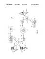
- FIG. 1is block diagram of a network telephony system according to one embodiment of the present invention
- FIG. 2is a block diagram showing a system for associating notes on a telephony system according to an exemplary embodiment of the present invention
- FIG. 3is a block diagram of a data network telephone according to an exemplary embodiment of the present invention.
- FIG. 4is a block diagram of a portable information device (PID) according to an exemplary embodiment of the present invention
- FIG. 5is a stack layer diagram showing the layers of an IrDA stack
- FIG. 6is a block and stack layer diagram illustrating an embodiment of the protocol stacks in an exemplary embodiment of a PID linked to a data network telephone;
- FIG. 7is block and stack layer diagram illustrating an embodiment of the present invention in which a SIP call may be established
- FIG. 8is a message flow diagram illustrating exemplary message flow patterns that may occur in a note-taking session on a call initiated by a PID;
- FIG. 9is a block diagram illustrating an exemplary three-party call in which notes are associated with the call on PIDs.
- FIG. 10is a pictorial diagram showing a PID screen display of a call notes database application according to an exemplary embodiment of the present invention.
- FIG. 1is a block diagram showing an exemplary embodiment of a system 100 for providing shared workspace services according to the present invention.
- the systemincludes a data network 106 .
- a first voice communication device 108 a linked to a first access network 112 via connection 130may communicate over the data network 106 by connecting via the first access network 112 .
- a second voice communication device 108 bis linked to a second access network 114 through connection 136 and may communicate over the data network 106 by connecting via the second access network 114
- the data network 106 in the system 100typically includes one or more Local Area Networks (LANs) connected to one another or to a Wide-Area Network (WAN), such as an Internet Protocol (IP) network, to provide wide-scale data connectivity.
- LANsLocal Area Networks
- WANWide-Area Network
- IPInternet Protocol
- the data network 106may use Voice-Over-Packet (VOP) schemes in which voice signals are carried in data packets.
- VOPVoice-Over-Packet
- PSTNPublic Switched Telephone Network
- the data network 106may include one or more LANs such as Ethernet LANs and support data transport protocols for performing Voice-over-Intemet-Protocol (VoIP) techniques on the Internet.
- VoIPVoice-over-Intemet-Protocol
- an Internet Telephony gatewaymay be included within the system 100 to allow for voice connections to users connected by subscriber lines at a PSTN Central Office.
- the voice communication devices 108 a-btypically include a voice input, a voice output, and a voice processing system.
- the voice processing systemconverts voice sound to digital data signals that are communicated on a voice connection over the data network.
- the voice processing systemalso converts digital data signals received from the voice connection to voice sound.
- the voice communication devices 108 a-btypically include a central processing unit and memory to store and process computer programs. Additionally, each voice communication device 108 a-b typically includes a unique network address, such as an IP address, in memory to uniquely identify it to the data network 106 and to permit data packets to be routed to the device.
- a first PID 110 a linked to the first voice communication device 108 a via link 109 amay communicate over the data network 106 by connecting via the first access network 112 .
- a second PID 110 b linked to the second voice communication device 108 b via link 109 bmay communicate over the data network 106 by connecting via the second access network 114 .
- the PIDs 110 a-beach may store user attributes in a user information database.
- the user attributesmay contain such information as a user identifier (such as a SIP URL or other telephony locator), schedule information, and other information that is associated with a user of the PID 110 a or 110 b .
- the PIDS 110 a-beach include a user interface allowing a user to easily enter and retrieve data.
- the user interfaceincludes a pressure-sensitive display that allows a user to enter input with a stylus or other device.
- a PID with such an interfaceis a PDA (Personal Digital Assistant), such as one of the PaIMTM series of PDAs offered by 3Com® Corporation.
- the PIDs 110 a-bmay also include other functionality, such as wireless phone or two-way radio functionality.
- Links 109 a-bare point-to-point links, and may entirely or partially wireless, or they may be hard-wired connections.
- Each of the links 109 a-bis preferably a wireless link, such as an infrared link specified by the Infrared Data Association (IrDA) (see irda.org for further information) or a radio frequency (RF) link such as the Bluetooth system (see www.bluetooth.com for further information).
- the point-to-point linkcan also be a hardwired connection, such as an RS-232 serial port.
- the voice communication device 108 aincludes a handset with a receiver and transmitter similar or identical to handsets of traditional circuit-switched telephones.
- a console on which the handset sitsmay include the voice processing system, a display 116 , and a keypad 118 .
- a portion of the voice communication device 108 autilizes an NBX 100TM communication system phone offered by 3Com® Corporation.
- the voice communication device 108 amay include any device having voice communications capabilities.
- a personal computer having a microphone input and speaker outputmay also be used to implement the voice communication device 108 a .
- Other configurationsare also intended to be within the scope of the present invention.
- the details relating to operation of the voice communication devices 108 a and 108 bdepend on the nature of the data network 106 and the nature of the access networks 112 and 114 connecting the voice communication devices 108 a and 108 b to each other and/or to other network entities.
- the access networks 112 and 114typically include any high bandwidth network adapted for data communications, i.e. a network having greater than 64,000 bits-per-second (bps) bandwidth.
- the access networks 112 and 114may link to the voice communication devices 108 a-b using an Ethernet LAN, a token ring LAN, a coaxial cable link (e.g.
- CATVadapted for digital communication
- DSLdigital subscriber line
- ISDNintegrated services digital network
- the access networks 112 and 114may also include the PSTN and link the voice communications devices 108 a-b by an analog modem. Further details regarding specific implementations are described below, with reference to FIGS. 2 through 10.
- PID-Enabled Data Network Telephony System 100 in FIG. 1may be used to enable a user to take notes with a PID while participating in a voice conversation with a second user on a call that was initiated by the PID.
- a user of the first PID, 110 ais able to select a communications partner, such a by selecting the communications partner in an address book stored in the first PID 110 a .
- the first PID 110 acan then be caused to transmit information about the communication partner to the first voice communication device 108 a across the first link 109 a , enabling the first voice communication device 108 a to attempt to complete a network telephony call to the communication partner, which may, for example, be located at the second voice communication device 108 b .
- the called communication partnercan receive call information, such as the parties involved, the time of day, etc., by causing the call information to be transmitted from the second voice communication device to the communication partner's PID, which may, for example be the second PID 110 b .
- the called communication partnercan point the second PID 110 b to the second voice communication device 108 b and cause the second PID 110 b to transmit a request for the call information via the second link 109 b .
- the second voice communication device 108 bwill then transmit the call information to the second PID 110 b via the second link 109 b , so that the call information can be stored in the second PID 110 b .
- the caller and the called communication partnermay proceed with a voice conversation while they each take notes on their respective PIDs 110 a and 110 b .
- the notes taken during the voice conversationare associated with the call information.
- the caller and the called communication partnermay later access the notes taken on the PIDs by searching by the name of the caller or called party, the date or time, or the subject matter contained in the notes, for example.
- the notes associated with the callmay also be synchronized with a PC or other device, to allow the user to access the notes on the PC or other device.
- a personal information manager application on a user's PCmay contain contact information, schedule information, email services, task lists, and other organizing functionality.
- the notes associated with the callmay be manually or automatically indexed for inclusion within the personal information manager, allowing the user to easily access the notes later. Automatic indexing might be performed by the note-taking application on the PID or on the personal information manager application in the PC, for example. Indexing categories could include the contact information of the parties to the call, date and time information based on the date and time information for the call, or the date and time information of an event referenced in the call notes, for example.
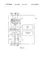
- FIG. 2is a block diagram showing one example of a system, such as the system 100 of FIG. 1 for providing shared workspace services according to the present invention.
- the system 200 in FIG. 2includes a local area network 212 , connected to a data network 206 by a first router 228 .
- a cable network 214is connected to the data network 206 by a second router 238 .
- FIG. 2illustrates the access networks as the local area network 212 and the cable network 214 , any other type of network may be used.
- the local area network 212 and/or the cable network 214may be replaced by ISDN, DSL, or any other high-speed data link.
- the local area network 212provides data connectivity to its network elements, such as a first data network telephone 208 a , a second data network telephone 208 b , and a first network telephony connection server 150 .
- the local area network 212 in FIG. 2is an Ethernet LAN operating according to the IEEE 802.3 specification, which is incorporated by reference herein; however, any other type of local area network may be used.
- the local area network 212uses the router 228 to provide the first data network telephone 208 a , the second data network telephone 208 b , and the first network telephony connection server 150 with access to the data network 206 .
- the router 228may perform routing functions using protocol stacks that include the Internet Protocol and other protocols for communicating on the Internet.
- the first network telephony connection server 150provides telephony registration, location and session initiation services for voice connections in which its members are a party.
- a usermay register for telephony service with an administrator of the first network telephony connection server 150 and receive a user identifier and a telephone identifier.
- the user identifier and telephone identifiermay be sequences of unique alphanumeric elements that callers use to direct voice connections to the user.
- the first network telephony connection server 150may register users by storing user records in a first registration database 152 in response to registration requests made by the user. Alternatively, registration information may be stored and maintained by a separate location server that may be accessed by the first network telephony connection server 150 .
- the call setup process and the user and telephone identifierspreferably conform to requirements defined in a call management protocol.
- the call management protocolis used to permit a caller anywhere on the data network to connect to the user identified by the user identifier in a data network telephone call.
- a data network telephone callincludes a call setup process and a voice exchange process.
- the call setup processincludes steps and message exchanges that a caller and callee perform to establish the telephone call.
- the actual exchange of voice signalsis performed using a data communications channel.
- the data communications channelincorporates other data transport and data formatting protocols, and preferably includes well-known data communications channels typically established over the Internet.
- the call management protocol used in FIG. 2is the Session Initiation Protocol (SIP), which is described in M. Handley et al., “SIP: Session Initiation Protocol,” IETF RFC 2543, March 1999, incorporated by reference herein. However, any other such protocol may be used. Other protocols include H.323, the Media Gateway Control Protocol (MGCP), MEGACO, etc.
- SIPSession Initiation Protocol
- MCPMedia Gateway Control Protocol
- MEGACOMedia Gateway Control Protocol
- the first network telephony connection server 150may be used to provide telephony service for mobile users.
- a usermay be registered to use the first network telephone 208 a (which is identified by its telephone identifier, such as a hardware device or a network device), but the user may move to a location near the second network telephone 208 b .
- the usermay re-register as the user of the second telephone 208 b . Calls that identify the user by the user's user identifier may reach the user at the second network telephone 208 b.
- the system 200 in FIG. 2also shows a cable network 214 connected to the data network 206 by a router 238 .
- the cable network 214provides data network access to its network elements, which in FIG. 2 include a third data network telephone 218 a and a second network telephony connection server 162 .
- the users of the data network telephone 218 a connected to the cable network 214may communicate over the data network 206 with the users of the data network telephones 208 a-b connected to the local area network 212 .
- the cable network 214includes any digital cable television system that provides data connectivity.
- datais communicated by radio frequency in a high-frequency coaxial cable.
- the cable network 214may include a head-end, or a central termination system that permits management of the cable connections to the users.
- the second network telephony connection server 162is preferably a SIP-based server that performs call initiation, maintenance, and tear down for data network telephones, such as the data network telephone 218 a connected to the cable network 214 .
- the second network telephony connection server 162may be similar or identical to the first network telephony connection server 150 connected to the local area network 212 .
- the system 200 shown in FIG. 2permits the data network telephones 208 a-b connected to the local area network 212 to communicate with the data network telephone 218 a connected to the cable network 214 .
- the system shown in FIG. 2uses SIP in order to establish, maintain, and tear down telephone calls between users.
- the UAresides at the SIP end stations, (e.g. the data network telephones), and contains two parts: a user agent client (UAC), which is responsible for issuing SIP requests, and a user agent server (UAS), which responds to such requests.
- UACuser agent client
- UASuser agent server
- the various network server typesmay be combined into a single server, such as the network telephony connection server 150 and 162 . Not all server types are required to implement the embodiments of the present invention.
- the communication services to be providedwill determine which servers are present in the communication system. Preferred embodiments of the present invention may be carried out using proxy servers.
- SIP operationinvolves a SIP UAC issuing a request, a SIP proxy server acting as end-user location discovery agent, and a SIP UAS accepting the call.
- a successful SIP invitationconsists of two requests: INVITE followed by ACK.
- the INVITE messagecontains a user identifier to identify the callee, a caller user identifier to identify the caller, and a session description that informs the called party what type of media the caller can accept and where it wishes the media data to be sent.
- User identifiers in SIP requestsare known as SIP addresses.
- SIP addressesare referred to as SIP Uniform Resource Locators (SIP-URLs), which are of the form sip:user@host.domain. Other addressing conventions may also be used.
- Redirect serversprocess an INVITE message by sending back the SIP-URL where the callee is reachable.
- Proxy serversperform application layer routing of the SIP requests and responses.
- a proxy servercan either be stateful or stateless.
- a stateful proxyholds information about the call during the entire time the call is up, while a stateless proxy processes a message without saving information contained in the message.
- proxiescan be either forking or non-forking.
- a forking proxycan, for example, ring several data network telephones at once until somebody takes the call.
- Registrar serversare used to record the SIP address (the SIP URL) and the associated IP address.
- a registrar serverThe most common use of a registrar server is for the UAC to notify the registrar where a particular SIP URL can be reached for a specified amount of time.
- the proxy or redirect serverforwards the request correctly.
- the central registrar/proxy serversuch as the first network telephony server 150
- the central registrar/proxy serveris the primary destination of all SIP messages trying to establish a connection with users on the local area network 212 .
- the first network telephony server 150is also the only destination advertised to the SIP clients outside the LAN 212 on behalf of all the SIP clients residing on the LAN 212 .
- the network telephony server 150relays all SIP INVITE messages to the appropriate final destination (or another SIP proxy), based on a database lookup using the first SIP database 152 . It also allows all mobile clients to register with their current locations.
- the second network telephony server 162is the primary destination of all SIP messages trying to establish a connection with the data network telephone 218 a connected to the cable network 214 .
- the second network telephony server 162is also the only destination advertised to the SIP clients outside the cable network 214 on behalf of all the SIP clients (e.g. data network telephones) residing on the cable network 214 .
- the second network telephony server 162relays all SIP INVITE messages to the appropriate final destination (or another SIP proxy), based on a database lookup using the second SIP database 164 .
- the data network telephones 208 a-b and 218 a in the system 200preferably have pre-programmed device identifiers (e.g. phone numbers), represented as SIP-URL's that are of the form sip: user@domain. Examples are sip: 8475551212@3Com.com or sip: johndoe@3Com.com.
- SIP-URL'sthat are of the form sip: user@domain. Examples are sip: 8475551212@3Com.com or sip: johndoe@3Com.com.
- each of the data network telephones 208 a-b and 218 asends a SIP REGISTER message to a default registrar, such as one of the network telephony servers 150 and 162 .
- a default registrarsuch as one of the network telephony servers 150 and 162 .
- the serverwill forward the call to the appropriate destination.
- a data network telephoneIf a data network telephone is moved to a new location, all calls to the associated SIP URL will still be properly routed to that device.
- the system in FIG. 2provides device mobility in the sense that calls will “follow” the data network telephone according to its SIP URL. This is especially useful if the data network telephones 208 a-b or 218 a are running the DHCP (Dynamic Host Configuration Protocol) so that when the location is changed, the IP address is also automatically changed.
- DHCPDynamic Host Configuration Protocol
- An advantage of the system in FIG. 2is that once a call is established between data network telephones, the data network 206 provides data connectivity for one or more data communications channels.
- the data network telephones 208 a , 208 b , and 218 acan communicate voice signals to one another as voice-over-data packets on voice-over-data channels.
- the data network telephones 208 a , 208 b , and 218 acan also communicate user data, such as graphical data as graphical data packets on graphical data channels.
- the graphical datamay be communicated to and from first and second PIDs 210 a and 220 a across links 209 a and 219 a to the data network telephones 208 a and 218 a , where the graphical data is assembled into packets for transmission and disassembled from the packets upon receipt, as part of the process for communicating the graphical data packets across the data network 206 and any access networks, such as the Ethernet LAN 212 and the cable network 214 .
- Other data channels besides voice-over-data channels and graphical data channelsmay also be provided and used for data transport.
- the data network telephones 208 a-bare preferably telephones that each include an Ethernet communications interface for connection to an Ethernet port.
- the Ethernet phones in FIG. 2support the Internet Protocol (IP), using an IP address that is either statically configured or obtained by access to a Dynamic Host Configuration Protocol (DHCP) server, which is not shown in FIG. 2 .
- IPInternet Protocol
- DHCPDynamic Host Configuration Protocol
- FIG. 3is a block diagram showing the data network telephone 208 a connected to the local area network 212 in FIG. 2 .
- the data network telephone 208 a in FIG. 3is connected to the network 212 by a network interface 270 .
- the network interface 270may, for example, be a network interface card, and may be in the form of an integrated circuit.
- a bus 248may be used to connect the network interface 270 with a processor 240 and a memory 242 .
- Also connected to the processorare user interface circuitry 260 and three alternative link interfaces to a PID, such as the PID 210 a.
- a first link interface 248includes an RS-232 serial connection and associated coupling hardware and mechanisms.
- the first alternative link interface 248may, for example, be a docking cradle for a PDA (Personal Digital Assistant), in which information can be transferred between the PDA and the data network telephone 208 a .
- the second alternative link interfacecomprises a first connection 254 , such as an RS-232 connection, along with infrared circuitry 250 for converting signals into infrared output and for accepting infrared input.
- An infrared interface 252may also be included within the second alternative link interface.
- the third alternative link interfacecomprises a first connection 256 , such as an RS-232 connection, along with radio-frequency circuitry 258 for converting signals into radio frequency output and for accepting radio frequency input.
- a radio frequency interface 259may also be included as part of the third alternative link interface.
- the three alternative link interfaces described aboveare merely examples, and additional means for implementing the link interface between the data network telephone 208 a and the PID 210 a may also be used. Although three link interfaces are shown in FIG. 3, there may be only one such interface in the data network telephone 208 a . More than one link interface may be included to improve flexibility and to provide redundancy in case of failure of one of the link interfaces.
- the user interface circuitry 260includes hardware and software components that access the functions of the handset, display, and keypad to provide user input and output resources for functions in the processor 240 .
- the user interface circuitryincludes a display interface 262 , a keypad interface 264 , an audio output interface 265 , and an audio input interface 267 .
- the audio input interface 267may receive voice signals from a microphone or other audio input device and convert the signals to digital voice information.
- the conversionpreferably conforms to the G.711 ITU Standard. Further processing of the digital signal may be performed in the audio input interface 267 , such as providing compression (e.g. using G.723.1 standard) or providing noise reduction, although such processing may also be performed in the processor 240 .
- the audio input interface 267may communicate an analog voice signal to the processor 240 for conversion to digital information within the processor 240 .
- the audio output interface 265receives digital information representing voice from the processor 240 and converts the information to audible sound, such as through a magnetic speaker.
- the audio output interface 265receives information in the form of G.711, although other processing such as decompression may be performed in the audio output interface 265 .
- the processor 240may convert digital information to analog voice signals and communicate the analog voice signals to the audio output interface 265 .
- the keypad interface 264 and the display interface 262include well-known device interfaces and respective signal processing techniques.
- the user interface circuitry 260may support other hardware and software interfaces.
- a videophone implementationmight also include a camera and monitor.
- the data network telephones of the present inventionare not limited to telephones or videophones—additional user interface types, for example, such as the ones needed for computer garnes, are also contemplated as being within the scope of the present invention.
- some of the features described here, such as the display interface 262are optional and serve to enhance the functionality of the first data network telephone 208 a.
- the processor 240may consist of one or more smaller processing units, including, for example, a programmable digital signal processing engine. In the preferred embodiment, the processor is implemented as a single ASIC (Application Specific Integrated Circuit) to improve speed and to economize space.
- the processor 240also may include an operating system, and application and communications software to implement the functions of the data network telephone 208 a .
- the operating systemmay be any suitable commercially available embedded or disk-based operating system, or any proprietary operating system.
- the processor 240includes a media engine 241 and a signaling stack 243 to perform the primary communications and application functions of the data network telephone 208 a .
- the purpose of the signaling stack in the exemplary data network telephone 208 ais to set up, manage, and tear down a call.
- a usermay use the keypad to enter a user-identifier to call.
- a PIDsuch as PID 210 a may transmit the user identifier of the party across the first link 209 a .
- the signaling stack 243receives the user entry and formats a request message to send to the user identified by the user identifier to initiate a telephone call.
- the location of the user identified by the user identifieris discovered, communication parameters, such as the supported voice CODEC types are exchanged, and a voice-over-data channel is established.
- communication parameterssuch as the supported voice CODEC types are exchanged, and a voice-over-data channel is established.
- other partiesmay be invited to the call if needed.
- the tear down phasethe call is terminated.
- the signaling protocol used in the data network telephone 208 a in FIG. 3is the SIP protocol.
- the signaling stackimplements a User Agent Client 244 and a User Agent Server 242 , in accordance with the SIP protocol.
- Alternative signaling protocolssuch as the ITU-T H.323 protocol, MGCP, MEGACO, and others, may also be used to implement the present invention.
- the media engine 241manages the communication over one or more data communications channels using network transport protocols and the network interface 270 .
- the media engine 241sends and receives data packets having a data payload for carrying data and an indication of the type of data is being transported.
- the media engine 241 in the data network telephones 208 amay sample the voice signals from the audio input 267 (or receive voice samples from the audio input 267 ), encode the samples, and build data packets on the sending side.
- the media engineOn the receiver side, in addition to performing the reverse operations, the media engine also typically manages a receiver buffer to compensate for network jitter. Similar procedures may be performed for other types of data, such as graphical data.
- the media engine 241may also include hardware and software components for performing registration functions 247 , voice-over-data functions 249 , display data functions 251 , and keypad output functions 253 .
- the media engine 241processes data that is received from the network 212 , and data to be sent over the network 241 .
- the media engine 241may determine from the type of data in the packet (such as by examining a packet header) whether packets contain sampled voice signals or other data types. Packets containing sampled voice signals are processed by the voice-over-data function 249 .
- the voice-over-data function 249preferably conforms to a protocol for formatting voice signals as digital data streams. While any'suitable protocol may be used, the media (i.e. the voice signal) is preferably transported via the Real Time Protocol (RTP), which itself is carried inside of UDP (User Datagram Protocol). RTP is described in H.
- RTPReal Time Protocol
- Packets containing data for use in registering the data network telephone 208 a with a network telephony serviceare processed by the registration function 247 .
- a usermay establish with the network telephony connection server 150 that calls addressed to the user's user identifier may be connected to the data network telephone 208 a .
- Registrationmay occur when the data network telephone 208 a sends a request to register to a service provider host, such as the network telephony connection server 150 .
- the service provider hostmay respond by setting the user's user identifier to correspond to the telephone identifier of the data network telephone 208 a , and by acknowledging the request with a status message to the data network telephone 208 a .
- a request to register the data network telephone 208 a to a default useris automatically sent during power-up of the data network telephone 208 a.
- the first data network telephone 208 amay be provisioned to provide selected network telephony services by establishing a data connection with a service provider, requesting the selected services, and receiving data that ensures that the services have been successfully provisioned.
- Such servicesmay include, for example, caller identification, call forwarding, voice mail and any other services offered by the network telephony service provider to enhance the capabilities of the first data network telephone 208 a .
- provisioning functionsis that services may be ordered for temporary use in a manner convenient to the user.
- Packets containing data for display on a display device of the data network telephone 208 aare processed by the display data function 251 .
- the display data function 251may be used for displaying, for example, the names and user identifiers of other parties to the call, the status of the telephone call, billing information, and other information.
- the media engine 241For data to be sent over the data network 212 , the media engine 241 formats the data as data packets in accordance with a selected protocol.
- the selected protocolis preferably a protocol that is supported by data network telephones that will receive the data being transported.
- the voice-over-data function 249formats voice samples according to the protocol used by the receiving data network telephone. In one preferred embodiment, the voice over data function 249 formats voice samples as RTP packets.
- the registration function 247 and the keypad output function 253may control the transport of data that does not represent voice signals.
- the data network telephones 208 b and 218 aare preferably similar or identical to the data network telephone 208 a .
- many of the features described in FIG. 3are optional and their inclusion depends on the services to be offered.
- PIDsPortable Information Devices
- FIG. 4is a block diagram showing the exemplary PID 210 a that can communicate via the link 209 a with the data network telephone 208 a connected to the LAN 212 .
- the PID 210 amay be linked to the data network telephone 208 a through a link interface 545 .
- a bus 580may be used to connect the point-to-point interface 545 with a processor 540 , a memory 542 , data storage 543 , and user interface circuitry 544 .
- the link interface 545 shown in FIG. 4illustrates three alternative link interfaces for establishing a link to a data network telephone, such as the data network telephone 208 a.
- a first link interface 546includes an RS-232 serial connection and associated coupling hardware mechanisms.
- the first alternative link interface 546may, for example, be for coupling with a PDA docking cradle, in which information can be transferred between the PDA and the data network telephone 208 a .
- the second alternative link interfacecomprises a first connection 548 , such as an RS-232 serial connection, along with infrared circuitry 250 for converting signals into infrared output and for accepting infrared input.
- An infrared interface 552may also be included within the second alternative link interface.
- the third alternative link interfacecomprises a first connection 554 , such as an RS-232 connection, along with radio-frequency circuitry 556 for converting signals into radio frequency output and for accepting radio frequency input.
- a radio frequency interface 558may also be included as part of the third alternative interface.
- the radio interface 554 / 556 / 558may be implemented according to the Bluetooth specifications, described at www.bluetooth.com.
- the three alternative link interfaces described aboveare merely exemplary, and additional means for implementing the interface between the PID 210 a and the data network telephone 208 a may also be utilized. Although three link interfaces are shown in FIG. 4, there may be only one such interface in the PID 210 a . More than one link interface may be included to improve flexibility and to provide redundancy in case of failure of one of the link interfaces.
- the user interface circuitry 544includes hardware and software components that provide user input and output resources for functions in the processor 540 .
- the user interface circuitryincludes a display output 562 , a display input 565 , and an additional input/output interface 567 .
- the display output 562preferably receives digital information representing graphical data from the processor 540 and converts the information to a graphical display, such as text and/or images, for display on a display screen, for example.
- the display input 565may receive data-inputs, such as graphical data inputs, from a user of the PID 210 a .
- the graphical data inputsare preferably entered by the user with a stylus on a pressure-sensitive display screen, and may include text, drawings, or other objects that are capable of being graphically presented.
- the additional input/output interface 567allows the user to enter other types of data besides graphical data into the PID 210 a .
- audio data, additional graphical data, or additional input, such as video camera input for examplemay be entered through the additional input/output interface 567 .
- Touch-sensitive screen buttonsare an exemplary method for a user to enter control data into the PID 210 a.
- the processor 540may include an operating system, as well as application and communication software, to implement the functions of the PID 210 a .
- the operating systemmay be any suitable commercially available operating system, or any proprietary operating system.
- the operating system and softwaremay be stored on data storage 543 , in the memory 542 , or the may be embedded in the processor 540 .
- the processor 540is shown connected to the data storage 543 through a bus 580 , other configurations may also be used.
- the memory 542may be configured other than as shown in FIG. 4, and may be embedded within the processor 540 .
- the PID 210 amay be able to send and receive data from the data network telephone 208 a across a point-to-point link, such as the point-to-point link 209 a shown in FIG. 1 .
- a usermay enter graphical data at the display input 565 .
- the graphical datamay be processed in the user interface circuitry 544 or it may go directly to the processor 540 or the memory 542 .
- the processor 540may also perform processing functions, such as compression.
- a graphical data.applicationmay be used to implement the display input, the display output, and the processing functions.
- a drawing applicationmay be used to accept graphical data input, the display input 565 from a user drawing with a stylus on the display screen of a PDA.
- a drawing applicationcould then display the drawing through the display output 562 to enable the user to see a visual representation of the drawing.
- the graphical data from the drawing applicationcan be transmitted through one of the point-to-point interfaces 545 , allowing the data to be received by the first data network telephone 208 a through the link 209 a .
- An application in the first data network telephone 208 areceives the graphical data, which may then be prepared for transmission across the data network 206 , such as by the media engine 241 shown in FIG. 3 .
- the graphical datais converted to graphical data packets and is communicated on a graphical data channel across the LAN 212 through the router 228 across the data network 206 through the second router 238 across the cable network 214 to the third data network telephone 218 a .
- the third data network telephone 218 amay then convert the graphical data packets received on the graphical data channel back into graphical data.
- the graphical datacan then be transmitted across the third point-to-point link 219 a to the third PID 220 a , where it may be displayed on a display screen on the PID 220 a to be viewed by the user of the third PID 220 a .
- the third PID 220 amay contain a similar drawing program as that which was referenced to the PID 210 a , allowing the user of the PID 220 a to modify the drawing and transmit the modifications back across the point-to-point link to the third data network telephone 218 a across the cable network 214 through the second router 238 across the data network 206 through the first router 228 across the LAN 212 to the first data network telephone 208 a across the point-to-point link and back to the first PID 210 a .
- This exampledemonstrates an alternative embodiment of the present invention, in which data received from a remote PID across a data network can be associated with a call at a near-end PID, in addition to the associated data that has been entered by the user of the near-end PID.
- the point-to-point link 209 amay be a serial bit stream between an application in the first PID 210 a and an application in the first data network telephone 208 a .
- the link 209 acould be an infrared link that is implemented with minimal stack interpretation.
- the link 209 a between PID 210 a and the first data network telephone 208 acan alternatively be implemented as an infrared link using all or parts of a specialized protocol, such as the Infrared Data Association (IrDA) protocol stack, where data is interpreted through the stack between application-layer processes at each end of the link.
- IrDAInfrared Data Association
- FIG. 5is a protocol diagram illustrating the layers of the IrDA protocol stack.
- An IrDA stackis implemented at each of the connection endpoints of an IrDA link.
- the required layers of an IrDA protocol stackare the physical layer 602 , the IrLAP layer 604 , the IRLMP layer 606 and the IAS layer 608 .
- the physical layer 602specifies optical characteristics of the link, encoding of data, and framing for various speeds.
- the IrLAP (Link Access Protocol) layer 604establishes the basic reliable connection between the two ends of the link.
- the IrLMP (Link Management Protocol) layer 606multiplexes services and applications on the IrLAP connection.
- the IAS (Information Access Service) layer 608provides a directory or “yellow pages” of services on an IrDA device.
- the IrDA protocolalso specifies a number of optional protocol layers, these protocol layers being TinyTP 610 , IrOBEX 612 , IrCOMM 614 and IrLAN 616 .
- TinyTPTransport Protocol
- IrOBEXInfrared Object Exchange protocol
- IrCOMM 614is a serial and parallel port emulation that enables existing applications that use serial and parallel communications to use IrDA without change.
- IrLANInfrared Local Area Network 616 enables walk-up infrared LAN access for laptops and other devices.
- the use of the optional layersdepends upon the particular application in the IrDA device.
- the IrDA protocol stackis defined by such standards documents as “IrDA Serial Infrared Physical Layer Link Specification”, “IrDA ‘IrCOMM’: Serial and Parallel Port Emulation over IR (Wire Replacement)”, “IrDA Serial Infrared Link Access Protocol (IrLAP)”, “IrDA Infrared Link Management Protocol (IrLMP)”, and “IrDA ‘Tiny TP’: A Flow-Control Mechanism for use with IrLMP”, and related specifications published by the IrDA and available at http://www.irda.org/standards/specifications.asp and is incorporated by reference herein.
- the data network telephones 208 a and 218 amerely provide a data tunnel for the data channel attendant to the infrared links, while the IrDA protocol stack is implemented at the endpoint PID devices 210 a and 220 a .
- IrDA stacksmay be implemented in the data network telephones as well.
- the IrDA protocol stackcan be implemented at each PID 210 a and 220 a , and the IrOBEX layer 612 can be used to transfer text and graphics object files, such as drawings or electronic business cards, end-to-end between PID devices connected via data network telephones and networks.
- the IrDA protocol stackcan be implemented at each PID 210 a and 220 a
- the IrOBEX layer 612can be used to transfer text and graphics object files, such as drawings or electronic business cards, end-to-end between PID devices connected via data network telephones and networks.
- Embodiments of the present inventionare not required to provide IrDA protocol support, however, certain advantages may be realized by implementing IrDA or other similar protocols.
- FIG. 6is a functional block diagram and protocol stack diagram illustrating an embodiment of the protocol stacks in the first PID 210 a and the first data network telephone 208 a that support link 209 a .
- the link interface circuitry 545 in the PID 210 aprovides the physical layer 656 , such as that specified by the Infrared Data Association (IrDA), that connects via link 209 a to the link interface circuitry 260 implementing a physical layer 664 in the first data network telephone 208 a .
- the data link layer 654 in the first PID 210 aprovides data link control for link 209 a in transferring data to and from a PID application client 652 .
- the first data network telephone 208 aincludes a data link layer 662 and a base application server 600 that is configured to synchronize connection and other functions with the PID application 652 in the first PID 210 a.
- the synchronization application client 652 in the PID 210 amay send the user's SIP URL across the link 209 a to the first data network telephone 208 a , where it is received by the synchronization application server 600 .
- the synchronization application server 600sends the SIP URL received from the PID 210 a across connection 230 and the Ethernet LAN 212 through connection 243 to the network telephony connection server 150 .
- the network telephony-connection server 150may store the SIP URL and the IP address of the associated data network telephone 208 a in the SIP database 152 so that the SIP URL is listed as being resident at the IP address of the data network telephone 208 a .
- the registration informationmight instead be stored with such a location server.
- SQLStructured Query Language
- the PID 210 ais registered with the network telephony connection server 150 , calls to the SIP URL for PID 210 a (or the user of the PID 210 a ) will be directed to the data network telephone 208 a.
- FIG. 7is a functional block and protocol stack diagram illustrating an embodiment of the present invention where a SIP connection is established from the first data network phone 208 a to the third data network phone 218 a through network connection 230 , first access network 212 , data network 206 , second access network 214 and network connection 236 .
- the routers 228 and 238 , and associated connections 232 a-b and 234 a-bare not shown to simplify the block diagram representation.
- the diagram of FIG. 7shows how user data, such as graphical or audio data, can be passed from one PID to another PID in one aspect of the present invention.
- the PID application 652 in PID 210 ais configured to send user data input through the user interface 650 through link 209 a to base application 660 in the first data network phone 208 a .
- base application 660is configured to define data channels for transport to the third data network telephone 218 a.
- SIPSession Description Protocol
- RFC 2327a Session Description Protocol
- SIP INVITE request for a connectionoptions for the requested connection that describe the number and type of media streams.
- a request for a connection that includes an audio stream and a bidirectional video stream using H.261might look like this:
- the called deviceincludes functionality to receive the connection as described in Table 1, then the called device will respond to the INVITE request with a “200 OK” response that includes the same option values. If the called device or party is unable or unwilling to receive such a connection, then it will respond with alternative option values for the connection. See RFC 2543 for further details regarding the negotiation of connection parameters in SIP.
- a first data channel for voice data and a second data channel for user datahave been negotiated by the base applications 660 in the first data network telephone 208 a and the base application 674 in the third data network telephone 218 a .
- the base applications 660 and 674transfer voice data between the AUDIO applications, such as applications including G.711 encoders, in each data network telephone 208 a and 218 a via the first data channel.
- the base application 660 in the first data network telephone 208 ais also configured to send the user data received via link 209 a from the first PID 210 a to the base application 674 in phone 218 a via the second data channel.
- the base application in the third data network telephone 218 ais configured to forward the user data received via the second data channel to the third PID 220 a via link 219 a .
- the PID application 688 in the third PID 220 athen outputs the user data to the user.interface 686 for output to the user of the third PID 220 a.
- the user data in FIG. 7can take a variety of forms.
- the user datacan be graphical data such as a text file containing information about the user of the first PID 210 a (e.g. an electronic business card).
- the user datacould also be graphical data in the form of drawing data generated by graphical applications in the first PID 210 a , where a user drawing on a touchscreen of the user interface 650 in PID 210 a generates corresponding graphical data that is transmitted via the user data channel to the third PID 220 a for display on the user interface 686 of the third PID 220 a .
- the media description for the user data in the user data channelcan be defined during connection setup to establish a connection appropriate to the type of data being transferred.
- RTP data packets for two or more types of dataare exchanged between the first data network telephone 208 a and the second data network telephone 218 a according to one of three possible methods.
- one RTP data channel (or RTP stream) on UDPcarries data packets in which both data types are present in a single split packets.
- Each such split packetcontains (1) a source port number and a destination port number in the UDP portion, and (2) a special payload sequentially including each of the data-types in the RTP portion.
- the special payload typecan be defined in the SDP described with reference to FIG. 6 . Other information is also contained in each packet as well.
- a separate RTP over UDP data channelis created for each of the different data types, and the RTP header indicates which type of data is contained in each packet. For example, voice data coded as G.711 might be assigned a payload type code of 0, while graphical data is assigned a payload type code of 190.
- a single RTP/UDP data channel(RTPJUDP stream) is created that contains data packets of two or more different types.
- the data typesare identified in a payload type field in the RTP header of each packet, enabling an underlying application to identify which data packets are voice data packets and which data packets are graphical data packets, for example.
- FIG. 8shows an example of the message flow patterns that may occur in a PID-initiated call in which PID notes are associated with the call.
- SIPis illustrated as the call management protocol; however, other call management protocols may also be used.
- UserAfirst selects UserB's name from an-address book application stored in UserA's PID 210 a .
- Address book applications for PIDsare known by those having skill in the art.
- An example of such an address book applicationis a contacts list stored in a PDA (Personal Digital Assistant).
- the selected entrypreferably includes contact information for UserB, including UserB's SIP URL, which is generically referred to in FIG. 8 as UserB_id.
- the PID 210 atransmits a request message 402 across the link 209 a to the first data network telephone 208 a to cause the first data network telephone 208 a to attempt to place a call to UserB.
- the PIDmay create an electronic record of the call attempt if it is desired to document call attempts by UserA.
- UserAmay instead initiate the call from the data network telephone 208 a , in which case UserA begins the telephone call by dialing User B's user identifier using the keypad 118 on the data network telephone 208 a.
- the SIP Invite message 470 from UserA at the data network telephone 208 ais the request to initiate a call to UserB.
- the data network telephone 208 asends the request to initiate the call to the data network telephony connection server 162 providing service to UserB.
- the request to initiate the call to UserBincludes UserB's user identifier (such as UserB's SIP URL) as the callee identifier, UserA's user identifier (such as UserA's SIP URL) as the caller identifier, and the protocols supported by UserA's data network telephone 208 (UserA's User Agent Client SDP).
- the telephony connection server 162sends the SIP Invite message 472 to the data network telephone 218 a identified in the SIP database 164 (or determined from a location server) as being associated with User B.
- the third data network telephone 218 aresponds with a response message 480 to the telephony connection server 162 .
- the telephony connection server 162receives the response message and sends the response message to UserA's data network telephone 208 a as shown at 478 .
- User A's data network telephone 208 areceives the response message and may prepare an acknowledgement message if called for by the protocol (e.g. the SIP protocol). If required, UserA's data network telephone 208 a sends a SIP Acknowledgement message 482 / 484 to UserB's data network telephone 218 a to complete the initiation of the telephone call.
- the protocole.g. the SIP protocol
- the PID 210 asends a request 406 for information about the current call to UserB.
- the calling PID 210 amay create a record when the call attempt is first initiated (i.e., when the PID 210 a first requests the first data network telephone 208 a to attempt the call to the data network associated with UserB).
- the PID 210 amay make a request 406 for information about the current call upon receiving the response message 478 from the data network telephone 218 a associated with UserB.
- the request for 406 for call informationcould be made at any other time during the call, such as at a time when UserA determines that he or she would like to take notes on the PID 210 a that are associated with the call in the form of a call record on the PID 210 a .
- the first data network telephone 208 atransmits the requested call information 408 to the PID.
- the call information 408may include details such as the data and time when the call was first attempted, the data and time when the call attempt was accepted, the data and time when the call attempt was completed by the transmission of the ACK message 482 / 484 , the name and/or other contact information of the called party, the call parameters, or any other information relating to the call between the UserA and the UserB.
- the UserBcan use his or her PID 220 a to make a similar request 410 for call information to the data network telephone 218 a .
- the data network telephone 218 atransmits the requested call information 412 to the PID 220 a.
- the requests for call information 406 and 410are preferably made by sending a request signal from the PIDs 210 a and 220 a to the data network telephones 208 a and 218 a .
- UserAcan point the first PID 210 a toward the first data network telephone 208 a to cause an infrared synchronization operation to occur across the link 209 a .
- Other alternative linking schemesas discussed with reference to FIGS. 3 and 4, may also be used.
- the PID application 652 and the base application 660 in the data network telephone 208 a(as shown in FIG. 7) may be used to control, record, and exchange information about the current call.
- the PID application 652also may maintain a database containing a record of calls which it associates with any notes taken by the UserA during the calls (or any information transferred, such as from UserB to UserA which UserA wishes to store in the PID 210 a and associate with the call record).
- the PID application 652may also implement the call association functionality using alternative approaches. In any case, it may be desirable for the PID application 652 to provide search capabilities to enable the UserA to search for notes by searching for the time or date of the call, the name of the communication partner or partners, or the subject matter of the call, for example.
- the PID 220 acan create the call record in a similar manner as was described for the PID 210 a.
- UserA's data network telephone 208 apreferably establishes a voice-over-data channel 488 with UserB's data network telephone 208 b to permit voice communication between UserA and UserB.
- the voice-over-data channel 488is preferably a data communications channel in which voice signals that have been converted to digital information are being carried as voice-over-data packets in accordance with a selected protocol, such as RTP over UDP/IP, as shown in FIG. 8 .
- the voice-over-data packetsinclude UserB's voice data in a first quantity of the voice-over-data packets, and contain UserA's voice data in a second quantity of the voice-over-data packets.
- UserB's voice-over-data packets and UserA's voice-over-data packetseach include an IP protocol component, a UDP component, an RTP component and a G. 72 x component in the exemplary embodiment shown in FIG. 8 .
- a second data channel 486is also shown in FIG. 8, which may be used to transmit graphical data, for example, for display on a data network telephone display screen 116 , or on a PID display screen 105 .
- the graphical datais transmitted from a data network telephone, such as the first data network telephone 208 a , to a PID, such as the first PID 210 a .
- the Users of PIDs 210 a and 220 aare able to utilize a shared workspace on their PIDs 210 a and 220 a while they participate in a conversation over the voice-over-data channel 488 .
- the second data channelis shown as an RTP/UDP/IP channel.
- Other transport protocol implementations, such as TCP/IPmay also be utilized.
- UserA and/or UserBmay desire to take notes based on the content of the conversation between UserA and UserB.
- UserAmay take notes on the first PID 210 a by using input means such as display input 565 or other input 567 as shown in FIG. 4 .
- input meanssuch as display input 565 or other input 567 as shown in FIG. 4 .
- UserAcould use a stylus to jot down notes of the content of the conversation between UserA and UserB.
- the PID 210 acontains voice-recording functionality
- UserAmay desire to record segments of the conversation between UserA and UserB for later reference by accessing the call record for the current call.
- other datamay be associated with the current call, such as video data or graphical data received across the data network on a data channel such as the second data channel 486 .
- a data channelsuch as the second data channel 486 .
- the PID 210 ait may be necessary for the PID 210 a to request the data network telephone 208 a to transmit the requested information to the PID 210 a over the link 209 a .
- UserBtakes notes 416 using the PID 220 a in a similar manner as described above for UserA taking notes 414 using PID 210 a.
- the callis terminated when one of the parties signals the end of the call.
- UserAsignals the end of the call by causing UserA's data network telephone 208 a to send a BYE message 490 / 492 to UserB's data network telephone 218 .
- UserBthen sends a “ 200 OK” response message 494 / 496 to UserA.
- the PID 210 amakes a request 418 for information about the call.
- the data network telephone 208 aprovides the requested information 420 to the PID 210 a .
- the PID 220 acan make a request 422 for information about the call to the data network telephone 218 a .
- the data network telephone 218 acan then transmit the requested call information 424 back to the PHD 220 a so that the call record may be completed.
- the PID 210 acan be used to initiate the BYE message 490 , in which case the PID 210 a is likely to have a record of the date and time when the call was terminated.
- UserAcan enter the date and time of the call termination into the PID 210 a manually.
- UserBcan perform a similar operation on PID 220 a upon termination of the call. (A similar manual operation could also be performed at the beginning of the call instead of synchronizing the PIDs with the data network telephones.)
- FIG. 8illustrates a typical two-party call.
- more than two partiesmay participate in the call.
- a three-party conference call between the UserA associated with the first PID 210 a and the first data network telephone 208 a , UserB associated with the third PID 220 a and the third data network telephone 218 a , and a UserC associated with the second PID 210 b and the second data network telephone 208 bmay be set up.
- FIG. 9shows a simplified representation of such a set-up.
- the access networks 212 and 214 , the data network 206 , the routers 228 and 238 , and the telephony connection servers 150 and 164have all been reduced to a single telephony network 900 to improve clarity.
- the set-up shown in FIG. 9illustrates the operation of an exemplary embodiment of a system for associating notes with a network telephony call between three parties.
- FIG. 9it is assumed that the calls in progress, and voice-over-data channels are in place between the first voice communication device 208 a and the second voice communication device 208 b , between the second voice communication device 208 b and the third voice communication device 218 a , and between the first communication device 208 a and the third voice communication device 218 a .
- FIG. 9uses the example of UserA inviting UserB and UserC to a barbecue at UserA's house.
- the PIDs 210 a , 210 b , and 220 ainclude respective PID touch-sensitive displays 902 , 904 , and 906 , in which a stylus or other input device can be used to enter graphical input information into the PIDs 210 a , 210 b and 220 a .
- Other input mechanismssuch as a keypad, may also be used.
- Each of the displays 902 , 904 , and 906show a call record containing a call information portion such as the call information portion 908 on display 902 in PID 210 a associated with UserA.
- the displays 902 , 904 , and 906also contain a notes portion in the call record, such as the notes portion 914 on display 902 in the PID 210 a associated with UserA.
- PIDs 210 b and 220 acontain similar notes portions 916 and 918 .
- UserAhas recorded notes in the note portion 914 listing the barbecue and the date of the barbecue as well as the people invited (UserB and UserC).
- UserAhas preferably entered this information using a stylus on the touch-sensitive display 902 of the PID 210 a .
- UserBhas taken notes on the notes portion 916 of the display 910 on PID 210 b , referencing the date and location of the barbecue and what UserB is supposed to bring to the barbecue.
- UserBmay also have used a stylus to enter the information in the notes portion 916 .
- An exemplary alternativewould be to use a keypad to enter the information in the notes portion 916 .
- Other alternativesare also possible and intended to be within the scope of the present invention.
- UserChas taken notes in the note portion 918 of the display 906 of the PID 220 a that list the date and location of the barbecue and show a map of how to get to UserA's house. UserC has also listed that he is to bring soda to the barbecue.
- the information in notes portion 918may be entered by UserC in a number of ways, as described above. Alternatively, some or all of the notes in the note portions 914 , 916 , and 918 may have been transmitted across a telephony network 900 from one party to another party in the call.
- the map in display 918may have been drawn by UserA, using a drawing application and a stylus on the PID 210 a . The map could then be transmitted across the link 209 a to the first data network telephone 208 a where the graphical data could be assembled into graphical data packets for transport in a graphical data channel between the first data network telephone 208 a and the third data network telephone 218 a , where the packets could be disassembled.
- the third PID 220 acould then request the graphical data containing the map information from the third data network telephone 218 a .
- the third data network telephone 218 acould then transmit the map information across the link 219 a to the third PID 220 a , where it could be integrated with the notes taken by UserC in the note portion 918 .
- links 209 a , 209 b , and 218 aare shown in FIG. 9, the links need not be utilized during much of the note-taking session unless user data is being transmitted across the network 900 , call information is being requested or received, or a call is being setup (or torn down).
- FIG. 10is a PID diagram showing an exemplary call notes database application 926 according to one embodiment of the present invention.
- the PID 210 amay display output from the call notes database application 926 on the display screen 902 .
- Included within the exemplary call notes database application 926are a call record list 928 and a search engine 932 .
- the call record list 928is shown as having headers relating to the call number, the date, the time, other parties to the call, and keywords relating to the call.
- Three callsare listed in the call record list 928 , including the call illustrated in FIG. 9, which is call number two in the call record list 928 . Call number two can be selected by UserA of the first PID 210 a to display the notes 914 that were taken during the call.
- the search engine 932allows UserA to search the call notes database by entering a call number, the date (or time) of a call, other parties to the call, or keywords, for example.
- the keywords field within the call notes databasemay require handwriting recognition processing if UserA enters the call notes via handwriting by using a stylus, for example. Alternatively, UserA may be able to specify identifying keywords as part of the note-taking process.
- the call notes database 926is merely one example of an application that may be used with the notes associated with the network telephony call according to aspects of the present invention. Other types of applications are also intended to be within the scope of the present invention.
- protocols of various typesare referenced throughout. While preferred and alternative embodiments may implement selected protocols, any suitable replacement protocol not mentioned, or any function not part of a protocol used to replace a corresponding function from a protocol may be implemented without departing from the scope of the invention.
Landscapes
- Engineering & Computer Science (AREA)
- Computer Networks & Wireless Communication (AREA)
- Signal Processing (AREA)
- Human Computer Interaction (AREA)
- Telephonic Communication Services (AREA)
Abstract
Description
Claims (29)
Priority Applications (1)
| Application Number | Priority Date | Filing Date | Title |
|---|---|---|---|
| US09/406,151US6795429B1 (en) | 1999-09-27 | 1999-09-27 | System and method for associating notes with a portable information device on a network telephony call |
Applications Claiming Priority (1)
| Application Number | Priority Date | Filing Date | Title |
|---|---|---|---|
| US09/406,151US6795429B1 (en) | 1999-09-27 | 1999-09-27 | System and method for associating notes with a portable information device on a network telephony call |
Publications (1)
| Publication Number | Publication Date |
|---|---|
| US6795429B1true US6795429B1 (en) | 2004-09-21 |
Family
ID=32990270
Family Applications (1)
| Application Number | Title | Priority Date | Filing Date |
|---|---|---|---|
| US09/406,151Expired - LifetimeUS6795429B1 (en) | 1999-09-27 | 1999-09-27 | System and method for associating notes with a portable information device on a network telephony call |
Country Status (1)
| Country | Link |
|---|---|
| US (1) | US6795429B1 (en) |
Cited By (46)
| Publication number | Priority date | Publication date | Assignee | Title |
|---|---|---|---|---|
| US20010026545A1 (en)* | 2000-03-28 | 2001-10-04 | Fujitsu Limited | Method and apparatus for registering IP terminal device in line-switching exchanger |
| US20010034718A1 (en)* | 2000-01-31 | 2001-10-25 | Shvat Shaked | Applications of automatic internet identification method |
| US20020181442A1 (en)* | 2001-05-29 | 2002-12-05 | Purshotam Rajani | Multimode personal communication system and method |
| US20030165128A1 (en)* | 2000-07-13 | 2003-09-04 | Rajendra Sisodia | Interactive communications system coupled to portable computing devices using short range communications |
| US20030172087A1 (en)* | 2000-06-27 | 2003-09-11 | Godwin Adrian Michael | Building management |
| US20030228888A1 (en)* | 2002-06-06 | 2003-12-11 | Adamson Peter S. | Managing user interface data on wireless devices |
| US20030233471A1 (en)* | 2002-06-17 | 2003-12-18 | Julian Mitchell | Establishing a call in a packet-based communications network |
| US20040064575A1 (en)* | 2002-09-27 | 2004-04-01 | Yasser Rasheed | Apparatus and method for data transfer |
| US20040131048A1 (en)* | 2003-01-06 | 2004-07-08 | Cook Debra Lee | Call setup request confirmation |
| US20040190529A1 (en)* | 2001-10-11 | 2004-09-30 | Fujitsu Limited | Apparatus for use with service providing system with integrated components in ad hoc network |
| US20040208185A1 (en)* | 2003-04-16 | 2004-10-21 | Lee Goodman | System and method for internet protocol telephony advertisement protocol |
| US20050041603A1 (en)* | 2003-08-18 | 2005-02-24 | Cisco Technology, Inc. | Supporting enhanced media communications |
| US6870830B1 (en)* | 2000-11-30 | 2005-03-22 | 3Com Corporation | System and method for performing messaging services using a data communications channel in a data network telephone system |
| US20050063360A1 (en)* | 2003-09-23 | 2005-03-24 | Sbc Knowledge Ventures, L.P. | System and method for facilitating packetized calls between managed networks |
| US20050130630A1 (en)* | 2002-02-01 | 2005-06-16 | Microsoft Corporation | System and method for creating a note related to a phone call |
| US20060030341A1 (en)* | 2004-08-06 | 2006-02-09 | Avaya Technology Corp. | Mobile desk phone |
| US20060077966A1 (en)* | 2004-10-07 | 2006-04-13 | Matsushita Electric Industrial, Co., Ltd. | IP telephone apparatus |
| US20060088143A1 (en)* | 2004-10-27 | 2006-04-27 | Tapaninen Veikko J | Communications device, computer program product, and method of providing notes |
| US20060153102A1 (en)* | 2005-01-11 | 2006-07-13 | Nokia Corporation | Multi-party sessions in a communication system |
| US20060208858A1 (en)* | 1999-12-29 | 2006-09-21 | Greg Griffith | Method of coupling wireless portable communications device to electronicmail server by public wireless communications network when out of communication with private wireless communications |
| US7113992B1 (en)* | 1999-11-08 | 2006-09-26 | Polycom, Inc. | Decomposition architecture for an MCU |
| US20070133524A1 (en)* | 2005-12-09 | 2007-06-14 | Yahoo! Inc. | Selectable replay of buffered conversation in a VOIP session |
| US20070133523A1 (en)* | 2005-12-09 | 2007-06-14 | Yahoo! Inc. | Replay caching for selectively paused concurrent VOIP conversations |
| US20070223930A1 (en)* | 2000-08-15 | 2007-09-27 | Lockheed Martin Corporation | Method and apparatus for infrared data communication |
| US20080012825A1 (en)* | 2001-10-17 | 2008-01-17 | Palm, Inc. | User interface technique for managing an active call |
| US20080043727A1 (en)* | 2006-06-30 | 2008-02-21 | Vonage Network Inc. | Method and apparatus for visual message indication in a VoIP system |
| US7412518B1 (en)* | 2000-05-09 | 2008-08-12 | Sun Microsystems, Inc. | Method and apparatus for proximity discovery of services |
| US20080205622A1 (en)* | 2004-01-08 | 2008-08-28 | Shoretel, Inc | Distributed Session-Based Data |
| US20090022286A1 (en)* | 2003-01-20 | 2009-01-22 | Avaya Inc. | Messaging advise in presence-aware networks |
| US20090220093A1 (en)* | 2005-12-05 | 2009-09-03 | Microsoft Corporation | Distribution Of Keys For Encryption/Decryption |
| US20100110938A1 (en)* | 2002-06-14 | 2010-05-06 | Polycom, Inc. | Multipoint Multimedia/Audio Conference Using IP Trunking |
| US7764777B2 (en) | 2000-05-04 | 2010-07-27 | Telemaze Llc | Branch calling and caller ID based call routing telephone features |
| US7865180B2 (en) | 2003-06-23 | 2011-01-04 | Palm, Inc. | Automated telephone conferencing method and system |
| EP2309710A1 (en) | 2009-10-12 | 2011-04-13 | Research In Motion Limited | Call note management on communication device |
| US8108516B2 (en) | 2002-02-14 | 2012-01-31 | Avaya Inc. | Presence tracking and name space interconnection techniques |
| US8150003B1 (en) | 2007-01-23 | 2012-04-03 | Avaya Inc. | Caller initiated undivert from voicemail |
| US8301581B2 (en) | 2009-09-24 | 2012-10-30 | Avaya Inc. | Group compositing algorithms for presence |
| US8677286B2 (en) | 2003-05-01 | 2014-03-18 | Hewlett-Packard Development Company, L.P. | Dynamic sizing user interface method and system for data display |
| US9166814B1 (en)* | 1996-12-16 | 2015-10-20 | Ip Holdings, Inc. | Server controlled network overlay for wireless devices |
| US9398152B2 (en) | 2004-02-25 | 2016-07-19 | Avaya Inc. | Using business rules for determining presence |
| US10225387B2 (en)* | 2016-09-29 | 2019-03-05 | Beijing Xiaomi Mobile Software Co., Ltd. | Call processing method and device |
| SE1751443A1 (en)* | 2017-11-23 | 2019-05-24 | Telia Co Ab | A method and a device for facilitating communication between end users |
| US10496190B2 (en) | 2017-01-25 | 2019-12-03 | Microsoft Technology Licensing, Llc | Redrawing a user interface based on pen proximity |
| US11563834B2 (en) | 2000-06-29 | 2023-01-24 | Ching-Yi Lin | Phone appliance with display screen and methods for using the same |
| US11815954B2 (en) | 2018-07-10 | 2023-11-14 | Samsung Electronics Co., Ltd. | Method and electronic device for performing operation on basis of bending |
| WO2024031419A1 (en)* | 2022-08-10 | 2024-02-15 | Qualcomm Incorporated | Data channel communications associated with an internet protocol multimedia subsystem |
Citations (72)
| Publication number | Priority date | Publication date | Assignee | Title |
|---|---|---|---|---|
| US4313035A (en) | 1980-01-18 | 1982-01-26 | Bell Telephone Laboratories, Incorporated | Method of providing person locator service |
| US4953198A (en) | 1989-07-05 | 1990-08-28 | At&T Company | Public cordless telephone |
| US5448623A (en) | 1991-10-10 | 1995-09-05 | Space Systems/Loral, Inc. | Satellite telecommunications system using network coordinating gateways operative with a terrestrial communication system |
| US5497339A (en) | 1993-11-15 | 1996-03-05 | Ete, Inc. | Portable apparatus for providing multiple integrated communication media |
| EP0704788A2 (en) | 1994-09-22 | 1996-04-03 | AT&T Corp. | Communication apparatus |
| US5557658A (en) | 1991-06-20 | 1996-09-17 | Quantum Systems, Inc. | Communications marketing system |
| US5563937A (en) | 1994-03-18 | 1996-10-08 | At&T | Method and system for multi-channel data automatic call distribution |
| US5606594A (en) | 1994-01-27 | 1997-02-25 | Dell Usa, L.P. | Communication accessory and method of telecommunicating for a PDA |
| US5646945A (en) | 1994-03-15 | 1997-07-08 | Alcatel N.V. | Telecommunications system and telecommunications terminal equipment |
| WO1997031492A1 (en) | 1996-02-21 | 1997-08-28 | International Business Machines Corporation | Distributed architecture for services in a telephony system |
| WO1997033421A1 (en) | 1996-03-06 | 1997-09-12 | Bell Communications Research, Inc. | Personal communications internetworking |
| WO1998000988A2 (en) | 1996-07-01 | 1998-01-08 | Ericsson Inc. | Method and apparatus for communicating information on mobile station position within a cellular telephone network |
| WO1998004065A1 (en) | 1996-07-24 | 1998-01-29 | Bell Communications Research, Inc. | System and method for providing customer contact services through a customer contact services node/internet gateway |
| US5727057A (en) | 1994-12-27 | 1998-03-10 | Ag Communication Systems Corporation | Storage, transmission, communication and access to geographical positioning data linked with standard telephony numbering and encoded for use in telecommunications and related services |
| WO1998010538A1 (en) | 1996-09-09 | 1998-03-12 | Leblanc Frederick W | Location of a mobile station using a plurality of commercial wireless infrastructures |
| US5732216A (en) | 1996-10-02 | 1998-03-24 | Internet Angles, Inc. | Audio message exchange system |
| US5732074A (en) | 1996-01-16 | 1998-03-24 | Cellport Labs, Inc. | Mobile portable wireless communication system |
| WO1998016051A1 (en) | 1996-10-07 | 1998-04-16 | Mitel Corporation | Network control of telephony services using downloadable applications |
| US5742905A (en) | 1994-09-19 | 1998-04-21 | Bell Communications Research, Inc. | Personal communications internetworking |
| WO1998030008A1 (en) | 1996-12-31 | 1998-07-09 | Mci Communications Corporation | Internet phone system and directory search engine using same |
| EP0858202A2 (en) | 1997-02-10 | 1998-08-12 | Nokia Mobile Phones Ltd. | A graphic user interface for use with a telephone directory |
| WO1998037665A1 (en) | 1997-02-02 | 1998-08-27 | Fonefriend Systems, Inc. | Internet switch box, system and method for internet telephony |
| EP0869688A2 (en) | 1997-04-04 | 1998-10-07 | Nokia Mobile Phones Ltd. | A method and means for transmitting a service page in a communication system |
| US5838665A (en) | 1996-03-11 | 1998-11-17 | Integrated Technology, Inc. | Data network telephone adaptor device |
| EP0881848A2 (en) | 1997-05-29 | 1998-12-02 | Casio Computer Co., Ltd. | Communication system |
| US5850433A (en) | 1996-05-01 | 1998-12-15 | Sprint Communication Co. L.P. | System and method for providing an on-line directory service |
| US5875405A (en) | 1994-12-27 | 1999-02-23 | Nec Corporation | Method and system for registering abbreviated dialing numbers |
| WO1999012365A1 (en) | 1997-08-29 | 1999-03-11 | Telia Ab (Publ) | Communication system including means for transmitting internet addresses via sms |
| US5894473A (en) | 1996-02-29 | 1999-04-13 | Ericsson Inc. | Multiple access communications system and method using code and time division |
| US5894595A (en) | 1994-08-01 | 1999-04-13 | At&T Corp | Personal mobile communication system |
| WO1999019988A2 (en) | 1997-10-09 | 1999-04-22 | Infogear Technology Corporation | Method and system for network access over a low bandwidth link |
| EP0918423A2 (en) | 1997-10-15 | 1999-05-26 | Nokia Mobile Phones Ltd. | Mobile phone for Internet applications |
| US5915008A (en) | 1995-10-04 | 1999-06-22 | Bell Atlantic Network Services, Inc. | System and method for changing advanced intelligent network services from customer premises equipment |
| US5918172A (en) | 1996-09-27 | 1999-06-29 | Highwaymaster Communications, Inc. | Multiple number assignment module communication |
| WO1999035802A2 (en) | 1998-01-07 | 1999-07-15 | Microsoft Corp | System for delivering data content over a low bit rate transmission channel |
| US5930700A (en) | 1995-11-29 | 1999-07-27 | Bell Communications Research, Inc. | System and method for automatically screening and directing incoming calls |
| US5933778A (en) | 1996-06-04 | 1999-08-03 | At&T Wireless Services Inc. | Method and apparatus for providing telecommunication services based on a subscriber profile updated by a personal information manager |
| US5938757A (en) | 1989-06-02 | 1999-08-17 | Ludo Arden Bertsch | Programmable distributed appliance control system |
| WO1999045687A1 (en) | 1995-01-26 | 1999-09-10 | Yablon Jay R | Enhanced system for transferring, storing and using signalling information in a switched telephone network |
| US5960340A (en) | 1996-02-28 | 1999-09-28 | At&T Corporation | Automatic cellular telephone registration for universal telephone number service |
| DE19813179A1 (en) | 1998-03-25 | 1999-09-30 | Siemens Ag | Internet-telephone with telephone acting as client for Internet applications |
| US5970059A (en)* | 1995-01-10 | 1999-10-19 | Nokia Telecommunications Oy | Packet radio system and methods for a protocol-independent routing of a data packet in packet radio networks |
| US5991394A (en) | 1995-04-21 | 1999-11-23 | Rockwell International Corporation | Method and system for establishing voice communications using a computer network |
| US6006272A (en) | 1998-02-23 | 1999-12-21 | Lucent Technologies Inc. | Method for network address translation |
| US6020916A (en) | 1997-12-31 | 2000-02-01 | At&T Corp | Videophone multimedia interactive on-hold information menus |
| US6031904A (en) | 1996-10-23 | 2000-02-29 | Nortel Networks Corporation | Service order mechanism for telephone subscriber |
| US6044403A (en) | 1997-12-31 | 2000-03-28 | At&T Corp | Network server platform for internet, JAVA server and video application server |
| US6052369A (en)* | 1994-01-21 | 2000-04-18 | Nokia Telecommunications Oy | Network element in a mobile communication system and a method for packet data transmission in a mobile communication system |
| US6075992A (en) | 1997-10-22 | 2000-06-13 | Ericsson Inc. | Apparatus and method for automatically handling initiation of a call by a portable intelligent communications device |
| US6084584A (en) | 1996-10-01 | 2000-07-04 | Diamond Multimedia Systems, Inc. | Computer system supporting portable interactive graphics display tablet and communications systems |
| US6161134A (en) | 1998-10-30 | 2000-12-12 | 3Com Corporation | Method, apparatus and communications system for companion information and network appliances |
| US6163598A (en) | 1997-12-24 | 2000-12-19 | Nortel Networks Limited | Interactive graphic payphone |
| US6167040A (en)* | 1997-10-10 | 2000-12-26 | Nokia Telecommunications Oy | Speech transmission between terminals in different networks |
| US6175860B1 (en) | 1997-11-26 | 2001-01-16 | International Business Machines Corporation | Method and apparatus for an automatic multi-rate wireless/wired computer network |
| WO2001005078A2 (en) | 1999-07-12 | 2001-01-18 | Walter Jay Weingarten | Transparent systems for communication over computer networks |
| US6216158B1 (en) | 1999-01-25 | 2001-04-10 | 3Com Corporation | System and method using a palm sized computer to control network devices |
| US6240097B1 (en) | 1997-06-12 | 2001-05-29 | Coherence Technology Corporation | Method and apparatus for data channelization and hardware-based network operation and control |
| US6266539B1 (en) | 1998-06-12 | 2001-07-24 | Cisco Technology, Inc. | Telephone docking station for personal digital assistant |
| US6301609B1 (en) | 1999-07-07 | 2001-10-09 | Lucent Technologies Inc. | Assignable associate priorities for user-definable instant messaging buddy groups |
| US20010032189A1 (en) | 1999-12-27 | 2001-10-18 | Powell Michael D. | Method and apparatus for a cryptographically assisted commercial network system designed to facilitate idea submission, purchase and licensing and innovation transfer |
| US6308201B1 (en) | 1999-04-08 | 2001-10-23 | Palm, Inc. | System and method for sharing data among a plurality of personal digital assistants |
| US20010034695A1 (en) | 2000-03-02 | 2001-10-25 | Wilkinson William T. | Intellectual property financial markets method and system |
| US20020002523A1 (en) | 1999-03-17 | 2002-01-03 | Nir Kossovsky | Online patent and license exchange |
| US20020004775A1 (en) | 1999-03-17 | 2002-01-10 | Nir Kossovsky | Online patent and license exchange |
| US20020046187A1 (en) | 2000-03-31 | 2002-04-18 | Frank Vargas | Automated system for initiating and managing mergers and acquisitions |
| US6411965B2 (en) | 1989-08-23 | 2002-06-25 | Edisync Systems Llc | Remote multi-user editing system and method transmitting edit display information |
| US6414962B1 (en)* | 1998-03-02 | 2002-07-02 | Telefonaktiebolaget Lm Ericsson | Method and apparatus for caching location information of transmitting mobile stations |
| US20020095368A1 (en) | 2000-02-29 | 2002-07-18 | Bao Tran | Systems and methods for trading intellectual property |
| US20020095311A1 (en) | 2000-07-05 | 2002-07-18 | J.J. Donahue & Company | Method and apparatus for negotiating a contract over a computer network |
| US20020129056A1 (en) | 2000-12-11 | 2002-09-12 | Conant Michael V. | Method and apparatus for electronic negotiation of document content |
| US20020138764A1 (en) | 2001-02-01 | 2002-09-26 | Jacobs Bruce A. | System and method for an automatic license facility |
| US20020165726A1 (en) | 2001-05-07 | 2002-11-07 | Grundfest Joseph A. | System and method for facilitating creation and management of contractual relationships and corresponding contracts |
- 1999
- 1999-09-27USUS09/406,151patent/US6795429B1/ennot_activeExpired - Lifetime
Patent Citations (72)
| Publication number | Priority date | Publication date | Assignee | Title |
|---|---|---|---|---|
| US4313035A (en) | 1980-01-18 | 1982-01-26 | Bell Telephone Laboratories, Incorporated | Method of providing person locator service |
| US5938757A (en) | 1989-06-02 | 1999-08-17 | Ludo Arden Bertsch | Programmable distributed appliance control system |
| US4953198A (en) | 1989-07-05 | 1990-08-28 | At&T Company | Public cordless telephone |
| US6411965B2 (en) | 1989-08-23 | 2002-06-25 | Edisync Systems Llc | Remote multi-user editing system and method transmitting edit display information |
| US5557658A (en) | 1991-06-20 | 1996-09-17 | Quantum Systems, Inc. | Communications marketing system |
| US5448623A (en) | 1991-10-10 | 1995-09-05 | Space Systems/Loral, Inc. | Satellite telecommunications system using network coordinating gateways operative with a terrestrial communication system |
| US5497339A (en) | 1993-11-15 | 1996-03-05 | Ete, Inc. | Portable apparatus for providing multiple integrated communication media |
| US6052369A (en)* | 1994-01-21 | 2000-04-18 | Nokia Telecommunications Oy | Network element in a mobile communication system and a method for packet data transmission in a mobile communication system |
| US5606594A (en) | 1994-01-27 | 1997-02-25 | Dell Usa, L.P. | Communication accessory and method of telecommunicating for a PDA |
| US5646945A (en) | 1994-03-15 | 1997-07-08 | Alcatel N.V. | Telecommunications system and telecommunications terminal equipment |
| US5563937A (en) | 1994-03-18 | 1996-10-08 | At&T | Method and system for multi-channel data automatic call distribution |
| US5894595A (en) | 1994-08-01 | 1999-04-13 | At&T Corp | Personal mobile communication system |
| US5742905A (en) | 1994-09-19 | 1998-04-21 | Bell Communications Research, Inc. | Personal communications internetworking |
| EP0704788A2 (en) | 1994-09-22 | 1996-04-03 | AT&T Corp. | Communication apparatus |
| US5875405A (en) | 1994-12-27 | 1999-02-23 | Nec Corporation | Method and system for registering abbreviated dialing numbers |
| US5727057A (en) | 1994-12-27 | 1998-03-10 | Ag Communication Systems Corporation | Storage, transmission, communication and access to geographical positioning data linked with standard telephony numbering and encoded for use in telecommunications and related services |
| US5970059A (en)* | 1995-01-10 | 1999-10-19 | Nokia Telecommunications Oy | Packet radio system and methods for a protocol-independent routing of a data packet in packet radio networks |
| WO1999045687A1 (en) | 1995-01-26 | 1999-09-10 | Yablon Jay R | Enhanced system for transferring, storing and using signalling information in a switched telephone network |
| US5991394A (en) | 1995-04-21 | 1999-11-23 | Rockwell International Corporation | Method and system for establishing voice communications using a computer network |
| US5915008A (en) | 1995-10-04 | 1999-06-22 | Bell Atlantic Network Services, Inc. | System and method for changing advanced intelligent network services from customer premises equipment |
| US5930700A (en) | 1995-11-29 | 1999-07-27 | Bell Communications Research, Inc. | System and method for automatically screening and directing incoming calls |
| US5732074A (en) | 1996-01-16 | 1998-03-24 | Cellport Labs, Inc. | Mobile portable wireless communication system |
| WO1997031492A1 (en) | 1996-02-21 | 1997-08-28 | International Business Machines Corporation | Distributed architecture for services in a telephony system |
| US5960340A (en) | 1996-02-28 | 1999-09-28 | At&T Corporation | Automatic cellular telephone registration for universal telephone number service |
| US5894473A (en) | 1996-02-29 | 1999-04-13 | Ericsson Inc. | Multiple access communications system and method using code and time division |
| WO1997033421A1 (en) | 1996-03-06 | 1997-09-12 | Bell Communications Research, Inc. | Personal communications internetworking |
| US5838665A (en) | 1996-03-11 | 1998-11-17 | Integrated Technology, Inc. | Data network telephone adaptor device |
| US5850433A (en) | 1996-05-01 | 1998-12-15 | Sprint Communication Co. L.P. | System and method for providing an on-line directory service |
| US5933778A (en) | 1996-06-04 | 1999-08-03 | At&T Wireless Services Inc. | Method and apparatus for providing telecommunication services based on a subscriber profile updated by a personal information manager |
| WO1998000988A2 (en) | 1996-07-01 | 1998-01-08 | Ericsson Inc. | Method and apparatus for communicating information on mobile station position within a cellular telephone network |
| WO1998004065A1 (en) | 1996-07-24 | 1998-01-29 | Bell Communications Research, Inc. | System and method for providing customer contact services through a customer contact services node/internet gateway |
| WO1998010538A1 (en) | 1996-09-09 | 1998-03-12 | Leblanc Frederick W | Location of a mobile station using a plurality of commercial wireless infrastructures |
| US5918172A (en) | 1996-09-27 | 1999-06-29 | Highwaymaster Communications, Inc. | Multiple number assignment module communication |
| US6084584A (en) | 1996-10-01 | 2000-07-04 | Diamond Multimedia Systems, Inc. | Computer system supporting portable interactive graphics display tablet and communications systems |
| US5732216A (en) | 1996-10-02 | 1998-03-24 | Internet Angles, Inc. | Audio message exchange system |
| WO1998016051A1 (en) | 1996-10-07 | 1998-04-16 | Mitel Corporation | Network control of telephony services using downloadable applications |
| US6031904A (en) | 1996-10-23 | 2000-02-29 | Nortel Networks Corporation | Service order mechanism for telephone subscriber |
| WO1998030008A1 (en) | 1996-12-31 | 1998-07-09 | Mci Communications Corporation | Internet phone system and directory search engine using same |
| WO1998037665A1 (en) | 1997-02-02 | 1998-08-27 | Fonefriend Systems, Inc. | Internet switch box, system and method for internet telephony |
| EP0858202A2 (en) | 1997-02-10 | 1998-08-12 | Nokia Mobile Phones Ltd. | A graphic user interface for use with a telephone directory |
| EP0869688A2 (en) | 1997-04-04 | 1998-10-07 | Nokia Mobile Phones Ltd. | A method and means for transmitting a service page in a communication system |
| EP0881848A2 (en) | 1997-05-29 | 1998-12-02 | Casio Computer Co., Ltd. | Communication system |
| US6240097B1 (en) | 1997-06-12 | 2001-05-29 | Coherence Technology Corporation | Method and apparatus for data channelization and hardware-based network operation and control |
| WO1999012365A1 (en) | 1997-08-29 | 1999-03-11 | Telia Ab (Publ) | Communication system including means for transmitting internet addresses via sms |
| WO1999019988A2 (en) | 1997-10-09 | 1999-04-22 | Infogear Technology Corporation | Method and system for network access over a low bandwidth link |
| US6167040A (en)* | 1997-10-10 | 2000-12-26 | Nokia Telecommunications Oy | Speech transmission between terminals in different networks |
| EP0918423A2 (en) | 1997-10-15 | 1999-05-26 | Nokia Mobile Phones Ltd. | Mobile phone for Internet applications |
| US6075992A (en) | 1997-10-22 | 2000-06-13 | Ericsson Inc. | Apparatus and method for automatically handling initiation of a call by a portable intelligent communications device |
| US6175860B1 (en) | 1997-11-26 | 2001-01-16 | International Business Machines Corporation | Method and apparatus for an automatic multi-rate wireless/wired computer network |
| US6163598A (en) | 1997-12-24 | 2000-12-19 | Nortel Networks Limited | Interactive graphic payphone |
| US6044403A (en) | 1997-12-31 | 2000-03-28 | At&T Corp | Network server platform for internet, JAVA server and video application server |
| US6020916A (en) | 1997-12-31 | 2000-02-01 | At&T Corp | Videophone multimedia interactive on-hold information menus |
| WO1999035802A2 (en) | 1998-01-07 | 1999-07-15 | Microsoft Corp | System for delivering data content over a low bit rate transmission channel |
| US6006272A (en) | 1998-02-23 | 1999-12-21 | Lucent Technologies Inc. | Method for network address translation |
| US6414962B1 (en)* | 1998-03-02 | 2002-07-02 | Telefonaktiebolaget Lm Ericsson | Method and apparatus for caching location information of transmitting mobile stations |
| DE19813179A1 (en) | 1998-03-25 | 1999-09-30 | Siemens Ag | Internet-telephone with telephone acting as client for Internet applications |
| US6266539B1 (en) | 1998-06-12 | 2001-07-24 | Cisco Technology, Inc. | Telephone docking station for personal digital assistant |
| US6161134A (en) | 1998-10-30 | 2000-12-12 | 3Com Corporation | Method, apparatus and communications system for companion information and network appliances |
| US6216158B1 (en) | 1999-01-25 | 2001-04-10 | 3Com Corporation | System and method using a palm sized computer to control network devices |
| US20020004775A1 (en) | 1999-03-17 | 2002-01-10 | Nir Kossovsky | Online patent and license exchange |
| US20020002523A1 (en) | 1999-03-17 | 2002-01-03 | Nir Kossovsky | Online patent and license exchange |
| US6308201B1 (en) | 1999-04-08 | 2001-10-23 | Palm, Inc. | System and method for sharing data among a plurality of personal digital assistants |
| US6301609B1 (en) | 1999-07-07 | 2001-10-09 | Lucent Technologies Inc. | Assignable associate priorities for user-definable instant messaging buddy groups |
| WO2001005078A2 (en) | 1999-07-12 | 2001-01-18 | Walter Jay Weingarten | Transparent systems for communication over computer networks |
| US20010032189A1 (en) | 1999-12-27 | 2001-10-18 | Powell Michael D. | Method and apparatus for a cryptographically assisted commercial network system designed to facilitate idea submission, purchase and licensing and innovation transfer |
| US20020095368A1 (en) | 2000-02-29 | 2002-07-18 | Bao Tran | Systems and methods for trading intellectual property |
| US20010034695A1 (en) | 2000-03-02 | 2001-10-25 | Wilkinson William T. | Intellectual property financial markets method and system |
| US20020046187A1 (en) | 2000-03-31 | 2002-04-18 | Frank Vargas | Automated system for initiating and managing mergers and acquisitions |
| US20020095311A1 (en) | 2000-07-05 | 2002-07-18 | J.J. Donahue & Company | Method and apparatus for negotiating a contract over a computer network |
| US20020129056A1 (en) | 2000-12-11 | 2002-09-12 | Conant Michael V. | Method and apparatus for electronic negotiation of document content |
| US20020138764A1 (en) | 2001-02-01 | 2002-09-26 | Jacobs Bruce A. | System and method for an automatic license facility |
| US20020165726A1 (en) | 2001-05-07 | 2002-11-07 | Grundfest Joseph A. | System and method for facilitating creation and management of contractual relationships and corresponding contracts |
Non-Patent Citations (22)
| Title |
|---|
| "Understanding Packet Voice Protocols"; The International Engineering Consortium; http://www.iec.org. |
| 3COM SIP Solutions 1.0 benefits brochure. (4 total pages). |
| Anquetil, L.P. et al., Media Gateway Control Protocol and Voice Over IP Gateways. MGCP and VoIP Gateways Will Offer Seamless Interworking of New VoIP Networks with Today's Telephone Networks, Electrical Communication, (Apr. 1, 1999), pps. 151-157. |
| Dalgic, Ismail et al., True Number Portability and Advanced Call Screening in a SIP-Based IP Telephony System, IEEE Communications Magazine, vol. 37, No. 7, (Jul. 1999), pps. 96-101. |
| Dalgic, Ismail; Borella, Michael; Dean, Rick; Grabiec, Jacek; Mahler, Jerry; Schuster, Guido; and Sidhu, Ikhlaq, True Number Portability and Advanced Call Screening in a SIP-Based IP Telephony System, IEEE Communications Magazine, vol. 37, No. 7, Jul. 1999, pp. 96-101. (8 total pages). |
| Gessler, Stefan et al., PDAs as Mobile WWW Browsers, Computer Networks and ISDN Systems, vol. 28, No. 1, (Dec. 1995), pps. 53-59. |
| Handley/Schulzrinne/Schooler/Rosenberg, SIP: Session Initiation Protocol, Internet Engineering Task Force, draft-ietf-sip-rfc2543bis-02.ps. Sep. 4, 2000. (131 pages). |
| Handley/Schulzrinne/Schooler/Rosenberg, SIP: Session Initiation Protocol, Network Working Group, Request for Comments (RFC) 2543, Mar. 1999. (153 pages). |
| Hansson, Allan et al., Phone Doubler-A Step Towards Integrated Internet and Telephone Communities, Ericsson Review, No. 4, 1997, pps. 142-152. |
| International Search Report for PCT Application Serial No. PCT/US00/26094, Dated Jan. 31, 2001. |
| International Search Report for PCT Application Serial No. PCT/US00/26594, Dated Feb. 6, 2001. |
| International Search Report for PCT Application Serial No. PCT/US00/26618, Dated Feb. 19, 2001. |
| International Search Report for PCT Application Serial No. PCT/US00/26649, Dated Feb, 6, 2001. |
| International Search Report for PCT Application Serial No. PCT/US00/26650, Dated Feb. 19, 2001. |
| International Search Report for PCT Application Serial No. PCT/US00/41020, Dated Feb. 21, 2001. |
| Myers, Brad A.; Stiel, Herb; and Gargiulo, Robert, Collaboration Using Multiple PDAs Connected to a PC, Proceedings of the ACM 1998 conference on Computer supported cooperative work, Nov. 14-18, 1998, Seattle, WA. (total 11 pages). |
| Pepper, David J. et al., The Call Manager System: A Platform for Intelligent Telecommunications Services, Speech Communication, vol. 23, (1997), pps. 129-139. |
| Sidhu, Ikhlaq and Bezaitis, Andrew, Eat or be eaten, www.americasnetwork.com/issues/99issues/991101/991191_eat.htm, printed May 10, 2000. (6 total pages). |
| Terry, Douglas B. et al. Managing Stored Voice In the Etherphone System, Xerox Palo Alto Research Center vol. 1, (Feb. 1998), pps. 3-27, XP 000032477. |
| Watanabe, H. et al., Development of the BTRON-BrainPad, Proceedings 13<th >Tron Project International Symposium, Online!, (Dec. 4-7, 1996), pps. 95-103. |
| Watanabe, H. et al., Development of the BTRON-BrainPad, Proceedings 13th Tron Project International Symposium, Online!, (Dec. 4-7, 1996), pps. 95-103. |
| Zellweger, Polle T. et al. An Overview of the Etherphone System and Its Applications, Xerox Palo Alto Research Center (Mar. 1988), pps. 160-168, XP 000617541. |
Cited By (87)
| Publication number | Priority date | Publication date | Assignee | Title |
|---|---|---|---|---|
| US9166814B1 (en)* | 1996-12-16 | 2015-10-20 | Ip Holdings, Inc. | Server controlled network overlay for wireless devices |
| US7113992B1 (en)* | 1999-11-08 | 2006-09-26 | Polycom, Inc. | Decomposition architecture for an MCU |
| US20060208858A1 (en)* | 1999-12-29 | 2006-09-21 | Greg Griffith | Method of coupling wireless portable communications device to electronicmail server by public wireless communications network when out of communication with private wireless communications |
| US20010034718A1 (en)* | 2000-01-31 | 2001-10-25 | Shvat Shaked | Applications of automatic internet identification method |
| US7756748B2 (en)* | 2000-01-31 | 2010-07-13 | Trivnet Ltd. | Application of automatic internet identification methods |
| US20010026545A1 (en)* | 2000-03-28 | 2001-10-04 | Fujitsu Limited | Method and apparatus for registering IP terminal device in line-switching exchanger |
| US8457113B2 (en) | 2000-05-04 | 2013-06-04 | Telemaze Llc | Branch calling and caller ID based call routing telephone features |
| US8155298B2 (en) | 2000-05-04 | 2012-04-10 | Telemaze Llc | Tandem access controller within the public switched telephone network |
| US8175240B2 (en) | 2000-05-04 | 2012-05-08 | Telemaze Llc | Tandem access controller within the public switched telephone network |
| US7764777B2 (en) | 2000-05-04 | 2010-07-27 | Telemaze Llc | Branch calling and caller ID based call routing telephone features |
| US9083719B2 (en) | 2000-05-04 | 2015-07-14 | Focal Ip, Llc | Controller for the intelligent interconnection of two communication networks, and method of use for same |
| US8718252B2 (en) | 2000-05-04 | 2014-05-06 | Focal Ip, Llc | Tandem access controller within the public switched telephone network |
| US8848894B2 (en) | 2000-05-04 | 2014-09-30 | Focal Ip, Llc | Tandem access controller within the public switched telephone network |
| US7412518B1 (en)* | 2000-05-09 | 2008-08-12 | Sun Microsystems, Inc. | Method and apparatus for proximity discovery of services |
| US20030172087A1 (en)* | 2000-06-27 | 2003-09-11 | Godwin Adrian Michael | Building management |
| US7822709B2 (en)* | 2000-06-27 | 2010-10-26 | Conssero Plc | Building management |
| US11652914B2 (en) | 2000-06-29 | 2023-05-16 | Ching-Yi Lin | Phone appliance with display screen and methods of using the same |
| US11563834B2 (en) | 2000-06-29 | 2023-01-24 | Ching-Yi Lin | Phone appliance with display screen and methods for using the same |
| US20030165128A1 (en)* | 2000-07-13 | 2003-09-04 | Rajendra Sisodia | Interactive communications system coupled to portable computing devices using short range communications |
| US20070223930A1 (en)* | 2000-08-15 | 2007-09-27 | Lockheed Martin Corporation | Method and apparatus for infrared data communication |
| US7480462B2 (en)* | 2000-08-15 | 2009-01-20 | Lockheed Martin Corporation | Method and apparatus for infrared data communication |
| US6870830B1 (en)* | 2000-11-30 | 2005-03-22 | 3Com Corporation | System and method for performing messaging services using a data communications channel in a data network telephone system |
| US20020181442A1 (en)* | 2001-05-29 | 2002-12-05 | Purshotam Rajani | Multimode personal communication system and method |
| US20040190529A1 (en)* | 2001-10-11 | 2004-09-30 | Fujitsu Limited | Apparatus for use with service providing system with integrated components in ad hoc network |
| US7916123B2 (en)* | 2001-10-17 | 2011-03-29 | Hewlett-Packard Development Company, L.P. | User interface technique for managing an active call |
| US7812817B2 (en)* | 2001-10-17 | 2010-10-12 | Palm, Inc. | System and method for managing wireless communications utilizing a mobile device |
| US20080012825A1 (en)* | 2001-10-17 | 2008-01-17 | Palm, Inc. | User interface technique for managing an active call |
| US20100273466A1 (en)* | 2001-10-17 | 2010-10-28 | Palm, Inc. | User interface technique for managing an active call |
| US20050136907A1 (en)* | 2002-02-01 | 2005-06-23 | Microsoft Corporation | System and method for creating a note related to a phone call |
| US7215945B2 (en)* | 2002-02-01 | 2007-05-08 | Microsoft Corporation | System and method for creating a note related to a phone call |
| US7035622B2 (en)* | 2002-02-01 | 2006-04-25 | Microsoft Corporation | System and method for creating a note related to a phone call |
| US7035623B2 (en)* | 2002-02-01 | 2006-04-25 | Microsoft Corporation | System and method for creating a note related to a phone call |
| US20050130630A1 (en)* | 2002-02-01 | 2005-06-16 | Microsoft Corporation | System and method for creating a note related to a phone call |
| US8108516B2 (en) | 2002-02-14 | 2012-01-31 | Avaya Inc. | Presence tracking and name space interconnection techniques |
| US7272412B2 (en)* | 2002-06-06 | 2007-09-18 | Intel Corporation | Managing user interface data on wireless devices |
| US20030228888A1 (en)* | 2002-06-06 | 2003-12-11 | Adamson Peter S. | Managing user interface data on wireless devices |
| US8000319B2 (en) | 2002-06-14 | 2011-08-16 | Polycom, Inc. | Multipoint multimedia/audio conference using IP trunking |
| US20100110938A1 (en)* | 2002-06-14 | 2010-05-06 | Polycom, Inc. | Multipoint Multimedia/Audio Conference Using IP Trunking |
| US20030233471A1 (en)* | 2002-06-17 | 2003-12-18 | Julian Mitchell | Establishing a call in a packet-based communications network |
| US7340531B2 (en)* | 2002-09-27 | 2008-03-04 | Intel Corporation | Apparatus and method for data transfer |
| US20040064575A1 (en)* | 2002-09-27 | 2004-04-01 | Yasser Rasheed | Apparatus and method for data transfer |
| US7450563B2 (en)* | 2003-01-06 | 2008-11-11 | At&T Intellectual Property, Ii, L.P. | Call setup request confirmation |
| US20040131048A1 (en)* | 2003-01-06 | 2004-07-08 | Cook Debra Lee | Call setup request confirmation |
| US8218735B2 (en) | 2003-01-20 | 2012-07-10 | Avaya Inc. | Messaging advise in presence-aware networks |
| US8064574B2 (en) | 2003-01-20 | 2011-11-22 | Avaya Inc. | Messaging advise in presence-aware networks |
| US20090034700A1 (en)* | 2003-01-20 | 2009-02-05 | Avaya Inc. | Messaging advise in presence-aware networks |
| US20090022286A1 (en)* | 2003-01-20 | 2009-01-22 | Avaya Inc. | Messaging advise in presence-aware networks |
| US8107597B2 (en) | 2003-01-20 | 2012-01-31 | Avaya Inc. | Messaging advise in presence-aware networks |
| US8098799B2 (en) | 2003-01-20 | 2012-01-17 | Avaya Inc. | Messaging advise in presence-aware networks |
| US8014497B2 (en) | 2003-01-20 | 2011-09-06 | Avaya Inc. | Messaging advise in presence-aware networks |
| US8050388B2 (en) | 2003-01-20 | 2011-11-01 | Avaya Inc. | Messaging advise in presence-aware networks |
| US20040208185A1 (en)* | 2003-04-16 | 2004-10-21 | Lee Goodman | System and method for internet protocol telephony advertisement protocol |
| US7099306B2 (en)* | 2003-04-16 | 2006-08-29 | Level 3 Communications, Llc | System and method for internet protocol telephony advertisement protocol |
| US8677286B2 (en) | 2003-05-01 | 2014-03-18 | Hewlett-Packard Development Company, L.P. | Dynamic sizing user interface method and system for data display |
| US7865180B2 (en) | 2003-06-23 | 2011-01-04 | Palm, Inc. | Automated telephone conferencing method and system |
| US20150022624A1 (en)* | 2003-08-18 | 2015-01-22 | Cisco Technology, Inc. | Supporting Enhanced Media Communications Using a Packet-Based Communication Link |
| US20050041603A1 (en)* | 2003-08-18 | 2005-02-24 | Cisco Technology, Inc. | Supporting enhanced media communications |
| US9185051B2 (en)* | 2003-08-18 | 2015-11-10 | Cisco Technology, Inc. | Supporting enhanced media communications using a packet-based communication link |
| US8873561B2 (en)* | 2003-08-18 | 2014-10-28 | Cisco Technology, Inc. | Supporting enhanced media communications using a packet-based communication link |
| US20050063360A1 (en)* | 2003-09-23 | 2005-03-24 | Sbc Knowledge Ventures, L.P. | System and method for facilitating packetized calls between managed networks |
| US20080205622A1 (en)* | 2004-01-08 | 2008-08-28 | Shoretel, Inc | Distributed Session-Based Data |
| US8107612B2 (en)* | 2004-01-08 | 2012-01-31 | Shoretel, Inc. | Distributed session-based data |
| US9398152B2 (en) | 2004-02-25 | 2016-07-19 | Avaya Inc. | Using business rules for determining presence |
| US20060030341A1 (en)* | 2004-08-06 | 2006-02-09 | Avaya Technology Corp. | Mobile desk phone |
| US20060077966A1 (en)* | 2004-10-07 | 2006-04-13 | Matsushita Electric Industrial, Co., Ltd. | IP telephone apparatus |
| US20060088143A1 (en)* | 2004-10-27 | 2006-04-27 | Tapaninen Veikko J | Communications device, computer program product, and method of providing notes |
| WO2006045903A1 (en)* | 2004-10-27 | 2006-05-04 | Nokia Corporation | Communications device, and method of providing notes |
| US20060153102A1 (en)* | 2005-01-11 | 2006-07-13 | Nokia Corporation | Multi-party sessions in a communication system |
| US20090220093A1 (en)* | 2005-12-05 | 2009-09-03 | Microsoft Corporation | Distribution Of Keys For Encryption/Decryption |
| US8787580B2 (en)* | 2005-12-05 | 2014-07-22 | Microsoft Corporation | Distribution of keys for encryption/decryption |
| US20140321651A1 (en)* | 2005-12-05 | 2014-10-30 | Microsoft Corporation | Distribution of keys for encryption/decryption |
| US7869579B2 (en)* | 2005-12-09 | 2011-01-11 | Yahoo! Inc. | Selectable replay of buffered conversation in a VOIP session |
| US20070133523A1 (en)* | 2005-12-09 | 2007-06-14 | Yahoo! Inc. | Replay caching for selectively paused concurrent VOIP conversations |
| US20070133524A1 (en)* | 2005-12-09 | 2007-06-14 | Yahoo! Inc. | Selectable replay of buffered conversation in a VOIP session |
| US20080043727A1 (en)* | 2006-06-30 | 2008-02-21 | Vonage Network Inc. | Method and apparatus for visual message indication in a VoIP system |
| US8150003B1 (en) | 2007-01-23 | 2012-04-03 | Avaya Inc. | Caller initiated undivert from voicemail |
| US8301581B2 (en) | 2009-09-24 | 2012-10-30 | Avaya Inc. | Group compositing algorithms for presence |
| EP2309710A1 (en) | 2009-10-12 | 2011-04-13 | Research In Motion Limited | Call note management on communication device |
| US8412174B2 (en) | 2009-10-12 | 2013-04-02 | Research In Motion Limited | Call note management on communication device |
| US20110086627A1 (en)* | 2009-10-12 | 2011-04-14 | Research In Motion Limited | Call note management on communication device |
| US8787897B2 (en) | 2009-10-12 | 2014-07-22 | Blackberry Limited | Call note management on communication device |
| US10225387B2 (en)* | 2016-09-29 | 2019-03-05 | Beijing Xiaomi Mobile Software Co., Ltd. | Call processing method and device |
| US10496190B2 (en) | 2017-01-25 | 2019-12-03 | Microsoft Technology Licensing, Llc | Redrawing a user interface based on pen proximity |
| SE1751443A1 (en)* | 2017-11-23 | 2019-05-24 | Telia Co Ab | A method and a device for facilitating communication between end users |
| US10623552B2 (en) | 2017-11-23 | 2020-04-14 | Telia Company Ab | Method and a device for facilitating communication between end users |
| US11815954B2 (en) | 2018-07-10 | 2023-11-14 | Samsung Electronics Co., Ltd. | Method and electronic device for performing operation on basis of bending |
| WO2024031419A1 (en)* | 2022-08-10 | 2024-02-15 | Qualcomm Incorporated | Data channel communications associated with an internet protocol multimedia subsystem |
Similar Documents
| Publication | Publication Date | Title |
|---|---|---|
| US6795429B1 (en) | System and method for associating notes with a portable information device on a network telephony call | |
| US6577622B1 (en) | System and method for using a portable information device to establish a conference call on a telephony network | |
| US6741586B1 (en) | System and method for sharing computer screens over a telephony network | |
| US6446127B1 (en) | System and method for providing user mobility services on a telephony network | |
| US6681252B1 (en) | System and method for interconnecting portable information devices through a network based telecommunication system | |
| US6870830B1 (en) | System and method for performing messaging services using a data communications channel in a data network telephone system | |
| US6857072B1 (en) | System and method for enabling encryption/authentication of a telephony network | |
| US6584490B1 (en) | System and method for providing call-handling services on a data network telephone system | |
| US6937699B1 (en) | System and method for advertising using data network telephone connections | |
| US6744759B1 (en) | System and method for providing user-configured telephone service in a data network telephony system | |
| US6914897B1 (en) | System and method for accessing radio programs using a data network telephone in a network based telecommunication system | |
| US6650901B1 (en) | System and method for providing user-configured telephone service in a data network telephony system | |
| US6856616B1 (en) | System and method for providing service provider configurations for telephones using a central server in a data network telephony system | |
| US6731630B1 (en) | Flexible dial plan for a data network telephony system | |
| KR101130398B1 (en) | System and methods for facilitating third-party call and device control | |
| US20070019627A1 (en) | Virtual PBX Based on SIP and Feature Servers | |
| CN101107830A (en) | Method for multi-channel multi-equipment call forwarding | |
| KR100602638B1 (en) | Voice service system and its connection method | |
| EP1652359A2 (en) | Method and system for suppressing early media in a communications network | |
| JP2003517764A (en) | SIP-based feature control system and method | |
| Anerousis et al. | TOPS: An architecture for telephony over packet networks | |
| US7016675B1 (en) | System and method for controlling telephone service using a wireless personal information device | |
| US20040062382A1 (en) | Multimedia augmented call coverage | |
| KR20040073793A (en) | System and method for Controlling network address translation and session | |
| WO2001041416A2 (en) | Personalizing a data network appliance on a data network telephony system |
Legal Events
| Date | Code | Title | Description |
|---|---|---|---|
| AS | Assignment | Owner name:3COM CORPORATION, CALIFORNIA Free format text:ASSIGNMENT OF ASSIGNORS INTEREST;ASSIGNORS:SCHUSTER, GUIDO M.;BELKIND, RONNEN;SIDHU, IKHLAQ S.;AND OTHERS;REEL/FRAME:010466/0131;SIGNING DATES FROM 19991203 TO 19991210 | |
| STCF | Information on status: patent grant | Free format text:PATENTED CASE | |
| FPAY | Fee payment | Year of fee payment:4 | |
| AS | Assignment | Owner name:HEWLETT-PACKARD COMPANY, CALIFORNIA Free format text:MERGER;ASSIGNOR:3COM CORPORATION;REEL/FRAME:024630/0820 Effective date:20100428 | |
| AS | Assignment | Owner name:HEWLETT-PACKARD COMPANY, CALIFORNIA Free format text:CORRECTIVE ASSIGNMENT TO CORRECT THE SEE ATTACHED;ASSIGNOR:3COM CORPORATION;REEL/FRAME:025039/0844 Effective date:20100428 | |
| FPAY | Fee payment | Year of fee payment:8 | |
| AS | Assignment | Owner name:HEWLETT-PACKARD DEVELOPMENT COMPANY, L.P., TEXAS Free format text:ASSIGNMENT OF ASSIGNORS INTEREST;ASSIGNOR:HEWLETT-PACKARD COMPANY;REEL/FRAME:027329/0044 Effective date:20030131 | |
| AS | Assignment | Owner name:HEWLETT-PACKARD DEVELOPMENT COMPANY, L.P., TEXAS Free format text:CORRECTIVE ASSIGNMENT PREVIUOSLY RECORDED ON REEL 027329 FRAME 0001 AND 0044;ASSIGNOR:HEWLETT-PACKARD COMPANY;REEL/FRAME:028911/0846 Effective date:20111010 | |
| FEPP | Fee payment procedure | Free format text:PAYOR NUMBER ASSIGNED (ORIGINAL EVENT CODE: ASPN); ENTITY STATUS OF PATENT OWNER: LARGE ENTITY Free format text:PAYER NUMBER DE-ASSIGNED (ORIGINAL EVENT CODE: RMPN); ENTITY STATUS OF PATENT OWNER: LARGE ENTITY | |
| AS | Assignment | Owner name:QUALCOMM INCORPORATED, CALIFORNIA Free format text:ASSIGNMENT OF ASSIGNORS INTEREST;ASSIGNORS:HEWLETT-PACKARD DEVELOPMENT COMPANY, L.P.;HEWLETT-PACKARD COMPANY;REEL/FRAME:030473/0035 Effective date:20130426 | |
| AS | Assignment | Owner name:3COM CORPORATION, CALIFORNIA Free format text:CORRECTIVE ASSIGNMENT TO CORRECT THE RECORDED EXECUTION DATE FOR INVENTOR: JACEK A. GRABIEC TO 12/03/1999 PREVIOUSLY RECORDED ON REEL 010466 FRAME 0131. ASSIGNOR(S) HEREBY CONFIRMS THE EXECUTION DATE ORIGINALLY RECORDED AS "12/10/1999" FOR INVENTOR: JACEK A. GRABIEC IS INCORRECT;ASSIGNORS:SCHUSTER, GUIDO M.;BELKIND, RONNEN;SIDHU, IKHLAQ S.;AND OTHERS;SIGNING DATES FROM 19991203 TO 19991210;REEL/FRAME:032494/0025 Owner name:HEWLETT-PACKARD DEVELOPMENT COMPANY, L.P., TEXAS Free format text:CORRECTIVE ASSIGNMENT TO CORRECT THE RECORDED EXECUTION DATE PREVIOUSLY RECORDED ON REEL 028911 FRAME 0846. ASSIGNOR(S) HEREBY CONFIRMS THE "RECORDED EXECUTION DATE: OCTOBER 10, 2011" IS INCORRECT;ASSIGNOR:HEWLETT-PACKARD COMPANY;REEL/FRAME:032493/0317 Effective date:20111108 | |
| FPAY | Fee payment | Year of fee payment:12 |