US6795068B1 - Prop input device and method for mapping an object from a two-dimensional camera image to a three-dimensional space for controlling action in a game program - Google Patents
Prop input device and method for mapping an object from a two-dimensional camera image to a three-dimensional space for controlling action in a game programDownload PDFInfo
- Publication number
- US6795068B1 US6795068B1US09/621,578US62157800AUS6795068B1US 6795068 B1US6795068 B1US 6795068B1US 62157800 AUS62157800 AUS 62157800AUS 6795068 B1US6795068 B1US 6795068B1
- Authority
- US
- United States
- Prior art keywords
- dimensional
- pixel group
- determining
- cylinder
- physical object
- Prior art date
- Legal status (The legal status is an assumption and is not a legal conclusion. Google has not performed a legal analysis and makes no representation as to the accuracy of the status listed.)
- Expired - Lifetime, expires
Links
Images


Classifications
- G—PHYSICS
- G06—COMPUTING OR CALCULATING; COUNTING
- G06F—ELECTRIC DIGITAL DATA PROCESSING
- G06F3/00—Input arrangements for transferring data to be processed into a form capable of being handled by the computer; Output arrangements for transferring data from processing unit to output unit, e.g. interface arrangements
- G06F3/01—Input arrangements or combined input and output arrangements for interaction between user and computer
- G06F3/03—Arrangements for converting the position or the displacement of a member into a coded form
- G06F3/033—Pointing devices displaced or positioned by the user, e.g. mice, trackballs, pens or joysticks; Accessories therefor
- G06F3/0354—Pointing devices displaced or positioned by the user, e.g. mice, trackballs, pens or joysticks; Accessories therefor with detection of 2D relative movements between the device, or an operating part thereof, and a plane or surface, e.g. 2D mice, trackballs, pens or pucks
- G06F3/03545—Pens or stylus
- G—PHYSICS
- G06—COMPUTING OR CALCULATING; COUNTING
- G06F—ELECTRIC DIGITAL DATA PROCESSING
- G06F3/00—Input arrangements for transferring data to be processed into a form capable of being handled by the computer; Output arrangements for transferring data from processing unit to output unit, e.g. interface arrangements
- G06F3/01—Input arrangements or combined input and output arrangements for interaction between user and computer
- G06F3/03—Arrangements for converting the position or the displacement of a member into a coded form
- G06F3/0304—Detection arrangements using opto-electronic means
- G—PHYSICS
- G06—COMPUTING OR CALCULATING; COUNTING
- G06F—ELECTRIC DIGITAL DATA PROCESSING
- G06F3/00—Input arrangements for transferring data to be processed into a form capable of being handled by the computer; Output arrangements for transferring data from processing unit to output unit, e.g. interface arrangements
- G06F3/01—Input arrangements or combined input and output arrangements for interaction between user and computer
- G06F3/03—Arrangements for converting the position or the displacement of a member into a coded form
- G06F3/033—Pointing devices displaced or positioned by the user, e.g. mice, trackballs, pens or joysticks; Accessories therefor
- G06F3/0346—Pointing devices displaced or positioned by the user, e.g. mice, trackballs, pens or joysticks; Accessories therefor with detection of the device orientation or free movement in a 3D space, e.g. 3D mice, 6-DOF [six degrees of freedom] pointers using gyroscopes, accelerometers or tilt-sensors
- G—PHYSICS
- G06—COMPUTING OR CALCULATING; COUNTING
- G06T—IMAGE DATA PROCESSING OR GENERATION, IN GENERAL
- G06T7/00—Image analysis
- G06T7/60—Analysis of geometric attributes
- G06T7/62—Analysis of geometric attributes of area, perimeter, diameter or volume
- G—PHYSICS
- G06—COMPUTING OR CALCULATING; COUNTING
- G06T—IMAGE DATA PROCESSING OR GENERATION, IN GENERAL
- G06T7/00—Image analysis
- G06T7/60—Analysis of geometric attributes
- G06T7/66—Analysis of geometric attributes of image moments or centre of gravity
- G—PHYSICS
- G06—COMPUTING OR CALCULATING; COUNTING
- G06T—IMAGE DATA PROCESSING OR GENERATION, IN GENERAL
- G06T7/00—Image analysis
- G06T7/70—Determining position or orientation of objects or cameras
- G06T7/73—Determining position or orientation of objects or cameras using feature-based methods
- A—HUMAN NECESSITIES
- A63—SPORTS; GAMES; AMUSEMENTS
- A63F—CARD, BOARD, OR ROULETTE GAMES; INDOOR GAMES USING SMALL MOVING PLAYING BODIES; VIDEO GAMES; GAMES NOT OTHERWISE PROVIDED FOR
- A63F2300/00—Features of games using an electronically generated display having two or more dimensions, e.g. on a television screen, showing representations related to the game
- A63F2300/10—Features of games using an electronically generated display having two or more dimensions, e.g. on a television screen, showing representations related to the game characterized by input arrangements for converting player-generated signals into game device control signals
- A63F2300/1012—Features of games using an electronically generated display having two or more dimensions, e.g. on a television screen, showing representations related to the game characterized by input arrangements for converting player-generated signals into game device control signals involving biosensors worn by the player, e.g. for measuring heart beat, limb activity
- A—HUMAN NECESSITIES
- A63—SPORTS; GAMES; AMUSEMENTS
- A63F—CARD, BOARD, OR ROULETTE GAMES; INDOOR GAMES USING SMALL MOVING PLAYING BODIES; VIDEO GAMES; GAMES NOT OTHERWISE PROVIDED FOR
- A63F2300/00—Features of games using an electronically generated display having two or more dimensions, e.g. on a television screen, showing representations related to the game
- A63F2300/10—Features of games using an electronically generated display having two or more dimensions, e.g. on a television screen, showing representations related to the game characterized by input arrangements for converting player-generated signals into game device control signals
- A63F2300/1087—Features of games using an electronically generated display having two or more dimensions, e.g. on a television screen, showing representations related to the game characterized by input arrangements for converting player-generated signals into game device control signals comprising photodetecting means, e.g. a camera
- A63F2300/1093—Features of games using an electronically generated display having two or more dimensions, e.g. on a television screen, showing representations related to the game characterized by input arrangements for converting player-generated signals into game device control signals comprising photodetecting means, e.g. a camera using visible light
Definitions
- the present inventionrelates to computer vision systems, and more particularly to a system in which an object is picked-up via an individual video camera, the camera image is analyzed to isolate the part of the image pertaining to the object, and the position and orientation of the object is mapped into a three-dimensional space.
- a three-dimensional description of the objectis stored in memory and used for controlling action in a game program, such as rendering of a corresponding virtual object in a scene of a video display.
- Pixel positions of the ball resolved in a given digital imagecan be related to a specific three-dimensional position of the ball in play and, using triangulation from respective video images, a series of image frames are analyzed by a least-squares method, to fit the positions of the ball to trajectory equations describing unimpeded segments of motion of the ball.
- Segenis concerned with determining the three-dimensional position of an object in motion from a plurality of two-dimensional video images captured at a point in time. Once the three-dimensional position of the “real” object is known, it is then possible to use this information to control a game program in any number of different ways which are generally known to game programmers.
- the system of Segenrelies on a plurality of video cameras for developing positional information about the object based on triangulation.
- the detected object of Segenis a simple sphere which does not require information about the orientation (e.g. inclination) of the object in space.
- the system of Segenis not capable of reconstructing position and orientation of an object, whether moving or at rest, from a two-dimensional video image using a single video camera.
- the calculated three-dimensional informationis used for fixing the position and orientation of the “virtual object” in a memory space of the game console, and then rendering of the image is performed by known projection processing to convert the three-dimensional information into a realistic perspective display.
- Another object of the inventionis to provide alternative interfaces for games, wherein rather than using a conventional joystick, the user can stand in front of a video camera connected to the game console device, and by physically moving or manipulating an object within view of a single camera, cause a corresponding action to occur in the game.
- Yet another object of the inventionis to provide methods for mapping two-dimensional information of a discriminated pixel group belonging to the manipulated object to a three-dimensional space, to provide a three-dimensional description of the position and orientation of the object in three dimensions from a single video camera image.
- Yet a further object of the inventionis to provide a three-dimensional description of an object which includes a rotational component of the manipulated object.
- a still further object of the inventionis to provide techniques for the selection of object colors which maximizes one's ability to discriminate, on the basis of color transitions, the pixel groups from a video image which belong unambiguously to the manipulated object and which provide the needed information for deriving a description of three-dimensional position and orientation of the object.
- FIG. 1is a block diagram showing an example of a configuration of a main part of a video game console which is adapted to receive an input from a digital video camera.
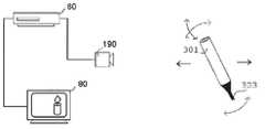
- FIG. 2is an illustration showing movement of a hand held prop, as an auxiliary input device, in front of a digital camera for causing corresponding action on a video display of a game program.
- FIG. 3is a block diagram showing the functional blocks required for tracking and discrimination of the prop as it is manipulated by the user.
- FIG. 4Aillustrates a prop device according to one aspect of the present invention
- FIG. 4Billustrates a process for mapping two-dimensional pixel data of a cylinder corresponding to the prop device shown in FIG. 4A to a three-dimensional space;
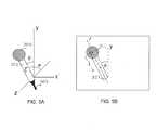
- FIG. 5Aillustrates a prop device according to another aspect of the present invention
- FIG. 5Billustrates a process for mapping two-dimensional pixel data of a combined sphere and cylinder corresponding to the prop device shown in FIG. 5A to a three-dimensional space.
- FIG. 6Aillustrates a prop device according to still another aspect of the present invention.
- FIG. 6Billustrates a process for mapping two-dimensional pixel data of stripes provided on a cylinder corresponding to the prop device shown in FIG. 6A to a three-dimensional space on the basis of color transitions at the stripes.
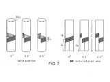
- FIG. 7illustrates a prop device having a helical stripe thereon, and provides a description of principles of another aspect of the present invention whereby a rotational component of the prop can be determined.
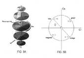
- FIGS. 8A and 8Bare graphs for describing a two-dimensional chrominance color space, for illustrating principles by which color transitions associated with colored stripes provided on a manipulated object are selected to maximize their detectability.
- FIG. 1is a block diagram of a configuration of a main part of a video game console 60 adapted for use with a manipulated object (prop) serving as an alternative input device.
- the game console 60constitutes a component of an overall entertainment system 110 according to the present invention which, as shown in FIG. 1 is equipped by a multiprocessor unit MPU 112 for control of the overall system 110 , a main memory 114 which is used for various program operations and for storage of data, a vector calculation unit 116 for performing floating point vector calculations necessary for geometry processing, an image processor 120 for generating data based on controls from the MPU 112 , and for outputting video signals to a monitor 80 (for example a CRT), a graphics interface (GIF) 112 for carrying out mediation and the like over a transmission bus between the MPU 112 or vector calculation unit 116 and the image processor 120 , an input/output port 124 for facilitating reception and transmission of data to and from peripheral devices, an internal OSD functional ROM (OSDROM) 126 constituted by, for example, a flash memory, for performing control of a kernel or the like, and a real time clock 128 having calendar and timer functions.
- OSDROMOSD functional ROM
- the main memory 114 , vector calculation unit 116 , GIF 112 , OSDROM 126 , real time clock 128 and input/output port 124are connected to the MPU 112 over a data BUS 130 .
- an image processing unit 138which is a processor for expanding compressed moving images and texture images, thereby developing the image data.
- the image processing unit 138can serve functions for decoding and development of bit streams according to the MPEG2 standard format, macroblock decoding, performing inverse discrete cosine transformations, color space conversion, vector quantization and the like.
- a sound systemis constituted by a sound processing unit SPU 171 for generating musical or other sound effects on the basis of instructions from the MPU 112 , a sound buffer 173 into which waveform data may be recorded by the SPU 171 , and a speaker 175 for outputting the musical or other sound effects generated by the SPU 171 .
- the speaker 175may be incorporated as part of the display device 80 or may be provided as a separate audio line-out connection attached to an external speaker 175 .
- a communications interface 140is also provided, connected to the BUS 130 , which is an interface having functions of input/output of digital data, and for input of digital contents according to the present invention.
- user input datamay be transmitted to, and status data received from, a server terminal on a network.
- An input device 132also known as a controller
- An optical disk device 136for reproduction of the contents of an optical disk 70 , for example a CD-ROM or the like on which various programs and data (i.e. data concerning objects, texture data and the like), are connected to the input/output port 124 .
- the present inventionincludes a digital video camera 190 which is connected to the input/output port 124 .
- the input/output port 124may be embodied by one or more input interfaces, including serial and USB interfaces, wherein the digital video camera 190 may advantageously make use of the USB input or any other conventional interface appropriate for use with the camera 190 .
- the above-mentioned image processor 120includes a rendering engine 170 , a main interface 172 , an image memory 174 and a display control device 176 (e.g. a programmable CRT controller, or the like).
- the rendering engine 170executes operations for rendering of predetermined image data in the image memory, through the memory interface 172 , and in correspondence with rendering commands which are supplied from the MPU 112 .
- a first BUS 178is connected between the memory interface 172 and the rendering engine 170
- a second BUSis connected between the memory interface 172 and the image memory 174 .
- First BUS 178 and second BUS 180respectively, have a bit width of, for example 128 bits, and the rendering engine 170 is capable of executing high speed rendering processing with respect to the image memory.
- the rendering engine 170has the capability of rendering, in real time, image data of 320 ⁇ 240 pixels or 640 ⁇ 480 pixels, conforming to, for example, NTSC or PAL standards, and more specifically, at a rate greater than ten to several tens of times per interval of from ⁇ fraction (1/60) ⁇ to ⁇ fraction (1/30) ⁇ of a second.
- the image memory 174employs a unified memory structure in which, for example, a texture rendering region and a display rendering region, can be set in a uniform area.
- the display controller 176is structured so as to write the texture data which has been retrieved from the optical disk 70 through the optical disk device 136 , or texture data which has been created on the main memory 114 , to the texture rendering region of the image memory 174 , via the memory interface 172 , and then to read out, via the memory interface 172 , image data which has been rendered in the display rendering region of the image memory 174 , outputting the same to the monitor 80 whereby it is displayed on a screen thereof.
- FIG. 2an overall system configuration by which a user holding a prop object manipulates the object in front of a digital video camera, for causing an action to occur in a video game.
- the propmay comprise a stick-like object which is made up of a handle 303 which is typically black in color, and a brightly colored cylinder (i.e. having a saturated color) 301 .
- a userstands in front of the video camera 190 , which may comprise a USB webcam or a digital camcorder connected to an input/output port 124 of a game console 60 such as the “Playstation 2”® manufactured by Sony Computer Entertainment Inc.
- the features of the object relating to the cylinderare picked up by the camera 190 , and processing (to be described later) is performed in order to isolate and discriminate a pixel group corresponding only the cylinder.
- the three-dimensional description of the object in the memory 114and a corresponding rendering of the object in the rendering area of image memory 174 , are continuously updated so that the position and orientation of the virtual object, or torch, on the monitor 80 changes as well.
- the essential information which must be providedis a three-dimensional description of the object, which in the case of FIG. 2 is a cylinder.
- the image which is picked up by the cameraprovides only two-dimensional pixel information about the object.
- FIG. 3is a block diagram showing the functional blocks used to track and discriminate a pixel group corresponding to the prop as it is being manipulated by the user. It shall be understood that the functions depicted by the blocks are implemented by software which is executed by the MPU 112 in the game console 60 . Moreover, not all of the functions indicted by the blocks in FIG. 3 are used for each embodiment. In particular, color transition localization is used only in the embodiment described in relation to FIGS. 6A and 6B, which shall be discussed below.
- a color segmentation processing step S 201is performed, whereby the color of each pixel is determined and the image is divided into various two-dimensional segments of different colors.
- a color transition localization step S 203is performed, whereby regions where segments of different colors adjoin are more specifically determined, thereby defining the locations of the image in which distinct color transitions occur.
- a step for geometry processing S 205is performed which, depending on the embodiment, comprises either an edge detection process or performing calculations for area statistics, to thereby define in algebraic or geometric terms the lines, curves and/or polygons corresponding to the edges of the object of interest.
- the pixel areawill comprise a generally rectangular shape corresponding to an orthogonal frontal view of the cylinder. From the algebraic or geometric description of the rectangle, it is possible to define the center, width, length and two-dimensional orientation of the pixel group corresponding only to the object.
- step S 207The three-dimensional position and orientation of the object are calculated in step S 207 , according to algorithms which are to be described in association with the subsequent descriptions of preferred embodiments of the present invention.
- the data of three-dimensional position and orientationalso undergoes a processing step S 209 for Kalman filtering to improve performance.
- Such processingis performed to estimate where the object is going to be at a point in time, and to reject spurious measurements that could not be possible, and therefore are considered to lie outside the true data set.
- Another reason for Kalman filteringis that the camera 190 produces images at 30 Hz, whereas the typical display runs at 60 Hz, so Kalman filtering fills the gaps in the data used for controlling action in the game program. Smoothing of discrete data via Kalman filtering is well known in the field of computer vision and hence will not be elaborated on further.
- FIG. 4Aa prop which is used according to the first embodiment shall be described, and in FIG. 4B a description is given which explains how three-dimensional information of the position and orientation of the prop of FIG. 4A is derived from a two-dimensional video image thereof.
- the propis a cylindrical body 301 having a single solid color attached to a handle 303 which is preferably black in color.
- a position of a given point ptypically the center of the object, in the X-Y plane and a depth quantity Z (i.e. the position of the point p on the Z axis) must be determined, together with angular information of the object in at least two different planes, for example, an inclination ⁇ of the object in the X-Y plane, and an inclination ⁇ of the object in the Y-Z plane.
- the actual physical length and diameter of the cylinder 301may be used for scaling, but are not essential for programming action in a game program since the virtual object shown on the display need not be of the same length and diameter, or even of the same shape, as the prop.
- FIG. 4Bshows a two-dimensional pixel image 305 of the object produced by the video camera 190 .
- a frontal orthogonal view of the cylindrical object 301is picked up in the video image which appears as a generally rectangular pixel group 307 , however, wherein the width of the pixel group can vary along the length l thereof as a result of the object being inclined in the phi ⁇ direction or as a result of the distance overall of the prop from the camera. It will be understood that the inclination in the phi ⁇ direction is not directly visible in the video image 305 .
- Area statisticsinclude the area, centroid, moment about the X-axis, moment about the Y-axis, principal moments, and the angle of principal moments, which typically are used for calculating moments of inertia of objects about a certain axis.
- the laminais of a shape having a geometric center, such as the rectangle in the case of FIG. 4B or a circle in the case of FIG. 5B (to be discussed later), the center of mass of such a lamina corresponds to the geometric center. More generally, if one knows the area statistics of the pixel region and, for example, that the two-dimensional shape is a rectangle, one can directly calculate its width, height and orientation. Similar calculations are possible with circular shapes to determine the center point and radius, for example. Representative calculations for cases of rectangles and circles can be found in standard college-level calculus or physics texts.
- the X-Y position of the center point pcan be derived directly from the image.
- the theta ⁇ quantityis taken directly from the image simply by knowing any line l, determined in accordance with the geometry processing step S 205 described above, which runs along the longitudinal axis of the pixel group 307 corresponding to the cylinder 301 .
- a longitudinal line l passing through the center point pis used for this purpose.
- Determination of the phi ⁇ quantityrequires some additional knowledge about the pixel width w in at least two different locations w 1 and w 2 wherein the ratio of the width quantities w 1 :w 2 provides a value which can be used for determining ⁇ . More specifically, if the cylinder 301 is inclined so that the top end thereof is closer to the camera 190 than the lower end of the cylinder, then, since the lower end of the cylinder is at a greater distance from the camera 190 , the pixel width quantity w 2 of the image will have a greater value than the pixel width quantity w 1 , and vice versa.
- the ratio w 1 :w 2is proportional to the inclination ⁇ of the cylinder 301 in the Y-Z plane, and therefore the phi quantity ⁇ can be determined from this ratio.
- a plurality of equidistant measurements of pixel widths between ends of the pixel group 307are taken, and averaging is performed to determine the ratio w 1 :w 2 .
- Determination of the depth quantity Zcan be done in different ways. However, it is important to recognize that the size and number of pixels making up the two-dimensional pixel group 307 are affected both by the inclination of the object in the ⁇ direction as well as by the actual distance of the physical object from the video camera 190 . More specifically, as the object inclines in the ⁇ direction, the apparent length of the object as seen by the video camera tends to shorten, so that the length l of the pixel group shortens as well. However, at the same time, as the object moves farther away from the camera along the Z-axis, the apparent size of the object overall, including its length l, also becomes smaller. Therefore, it is insufficient simply to look at the length l alone as an indicator of how far away from the camera the object is. Stated otherwise, the depth quantity Z must be determined as a function of both l and ⁇ .
- a phi-weighted value of lwhich we may call l ⁇
- the pixel length of l ⁇ in the imagewhich changes as the object is moved closer or farther from the camera while assuming that ⁇ stays constant, then can be used to determine the depth quantity Z since l ⁇ will be proportional to Z.
- Another method for determining depth Zis to count the total number of pixels in the pixel group 307 corresponding to the object. As the object gets closer to or farther from the camera, the number of pixels making up the pixel group 307 increases or decreases respectively, in proportion to the depth quantity Z. However, again, the number of pixels in the pixel group 307 is also affected by the inclination in the phi ⁇ direction, so the number of pixels N must first be weighted by phi ⁇ to result in a weighted quantity N ⁇ which is used for determining the depth quantity Z based on a proportional relationship between N ⁇ and Z.
- Yet another advantageous method for determining the depth quantity Zis to use the average width w avg of the rectangle, which is calculated as the sum of a given number of width measurements of the rectangle divided by the number of width measurements taken. It should be clear that the average width of the pixel group is affected only by Z and not by the phi-inclination of the cylinder. It is also possible to determine phi ⁇ from the ratio of the total length of the pixel group to the average width (i.e. l:w avg ), and moreover, wherein the sign of the phi-inclination can be determined based on whether w 1 is greater or less than w 2 .
- FIG. 5Aa prop which is used according to another embodiment shall be described, and in FIG. 5B a description is given which explains how three-dimensional information of the position and orientation of the prop of FIG. 5A is derived from a two-dimensional video image thereof.
- the prop according to the second embodimentcomprises a cylindrical stick-shaped object, however in this case, a spherical object 309 of a different color is rigidly affixed to one end of the cylinder 301 .
- a distal end of the cylindermay be provided which protrudes just slightly and is visible from an upper end of the sphere 309 .
- the sphere 309provides a simplified means for determining the depth quantity Z and the inclination of the object in the phi ⁇ direction, which does not require measurement of relative widths of the cylinder 301 , and which does not require any weighting of the length quantity by phi ⁇ in order to determine the depth quantity Z.
- a pixel group 311 corresponding to the sphere 309 in the imageappears as a two-dimensional circle.
- a radius R and center point p s of the circleare determined according to area statistics calculations which have already been discussed above.
- the total number of pixels making up the pixel group 311 of the circlecan be counted for giving a pixel area of the circle. It will be appreciated that the circular pixel area will increase as the spherical object 309 comes closer to the camera 190 and vice versa, and therefore, since the total number of pixels in the pixel group 311 making up the circle is proportional to the depth quantity Z, the value for Z can be determined thereby.
- the shape and size of the circular pixel groupare not influenced as a result of the phi ⁇ angle of inclination. More specifically, even if the object overall is tilted in the phi direction, the sphere 309 and the pixel group 311 will retain their general shape and, unlike the length of the cylinder 301 , will not become foreshortened as a result of such tilting. Therefore, an advantage is obtained in that the total number of pixels of the pixel group making up the circle in the image can always be related proportionately to the depth quantity Z and, for determining Z, phi-weighting as in the previous embodiment is not required.
- Determination of inclination of the object in the theta ⁇ directionis done directly from the image, just as in the previous embodiment, by determining the angle theta ⁇ between a center longitudinal line of the pixel group 307 corresponding to the cylinder 301 and the Y-axis.
- Determining the angle of inclination in the phi ⁇ directionis handled somewhat differently than the previous embodiment. More specifically, such a quantity can be determined by knowledge of the depth quantity Z, determined as described above, and by the length l between the center point of the circle 311 and the center point of the pixel group 307 which corresponds to the cylinder 301 . For any known and fixed depth quantity Z, the length l (as viewed from the perspective of the camera) becomes shorter as the object is tilted in the phi ⁇ direction. Therefore, if the Z quantity is known, it is possible to determine, simply from the length l, the degree of inclination in the phi ⁇ direction, and it is not necessary to calculate a relative width quantity or ratio of widths, as in the embodiment shown by FIGS. 4A and 4B.
- FIG. 6Aillustrates a prop device according to still another aspect of the present invention.
- the propitself comprises a generally cylindrical body 301 .
- three stripes S 1 , S 2 and S 3 having a different color than the cylinder itselfare provided on the cylindrical body.
- the stripes S 1 , S 2 and S 3are each equal in width and are spaced equidistant from each other, at either end of the cylinder 301 and in the center thereof.
- a pixel group making up the cylinderis extracted from the image to provide a two-dimensional line along which to look for color transitions.
- positionsare determined at which color transitions along any line l in the longitudinal direction of the cylinder 301 occur.
- the chrominance values Cr and Cb which are output as part of the YCrCb signals from the video camera 190are detected.
- the angle ⁇is taken directly as the angle between the longitudinal line of the cylinder and the Y axis, basically in the same manner as the preceding embodiments.
- the ratio of the lengths l 1 :l 2is used. For example, in the case (as shown) in which the cylinder is inclined in the ⁇ direction toward the camera 190 , with the upper end of the cylinder being closer to the camera than the lower end, the length l 1 will appear longer to the camera 190 (since it is closer) than the length l 2 . It will also be appreciated that, although the apparent lengths l 1 and l 2 will also be affected by the overall distance Z of the object from the camera 190 , the ratio of these lengths l 1 :l 2 will not change and therefore this ratio provides a constant indication of the inclination of the cylinder 301 in the phi ⁇ direction.
- ⁇is determined from the ratio of l 1 and l 2 , and once phi ⁇ is known, the total depth quantity Z can be determined from the sum of l 1 and l 2 .
- Each of the tracking methods described abovecan be used to obtain five of the six degrees of freedom of the objects.
- the only one missingis the rotation of the cylinder about its axis.
- Information about the rotation of the cylinderwould seem difficult to obtain because cylinders are symmetric in rotation about this axis.
- the approach taken by the present invention to obtain this rotational componentis to add a helical stripe S H that goes around the cylinder 301 exactly once. As the cylinder 301 is rotated, the height of the stripe S H will correspond to the rotation angle.
- the cylinder 301(or the cylinder-part of the prop in the case of FIGS. 5A and 5B) includes the single helical strip S H thereon which goes around the object only once.
- Information pertaining to the helical stripeis extracted, either from the entire pixel group 313 which makes up the helical stripe or by using the color transitions corresponding to the helical stripe S H , in order to determine, using the geometry processing discussed above, a helix H which best fits to the stripe S H .
- a center line l of the pixel group corresponding to the cylinderis determined as described previously. Also the overall length l of the pixel group is determined.
- the camera 190only sees one side (or orthogonal projection) of the cylinder 301 at a time. Accordingly, the helix H determined from the extracted region of the camera image determines the degree of revolution of the cylinder 301 . More specifically, as shown, assuming no rotation (i.e. a rotational component of 0 degrees), a center line extending from one end to a point on the helix will have a first height h 1 , whereas if the object is rotated by 45 degrees, the height of the center line l between the lower end to the point where it intersects the helix H will have a shorter height h 2 . The condition shown by the far right-hand side of FIG.
- additional information with respect to the object and orientation of the cylinder 301 in three-dimensional spacecan be provided. Such information can be used to control the rotation of a virtual object, for example, when displayed in a game program.
- FIG. 8Ashows a diagram of a color space defined by luminance and radial coordinates of hue and saturation.
- Luminanceis the brightness or intensity of the color
- hueis the shift in the dominant wavelength of a spectral distribution
- saturationis the concentration of a spectral distribution at one wavelength.
- FIG. 8Bshows a two-dimensional chrominance color space corresponding to the Cr and Cb chrominance output signals of the video camera.
- colorcan be defined using radial coordinates corresponding respectively to hue and saturation.
- YCrCbrepresents each color by a single luma component (Y) and two components of chrominance Cr and Cb.
- Ymay be loosely related to brightness or luminance whereas Cr and Cb make up a quantities loosely related to hue.
- Cr and Cb chrominance signals for each pixelare defined by Cartesian coordinates which also can be used to determine a location within the color wheel corresponding to a certain hue and saturation.
- the color of the stripes S 1 , S 2 and S 3 and the color of the cylinder 301are chosen in such a way as to maximize stripe detectability for the video camera.
- Color-based trackingis notorious for its difficulties due to changes in lighting, which cause the apparent color to vary.
- the color of blueas perceived by the camera, to vary to such a degree that accurate detection of the object is made difficult.
- by looking for color transitions instead of absolute colorsa more robust tracking solution can be attained. For example, in the embodiment of FIGS.
- highly saturated colors of blue and orangeare located at substantially diametrically opposed sides of the color wheel and are separated by a large distance D in the color space.
- the actual distance Dcan be calculated as the hypotenuse of a triangle having sides defined by ⁇ Cr (i.e. the difference in the Cr chrominance signal values for the two colors of blue and orange) and ⁇ Cb (i.e. the difference in the Cb chrominance signal values for the same two colors), and hence the actual distance D is the square root of ( ⁇ Cr) 2 +( ⁇ Cb) 2 , as already discussed above in equation (4).
- the methodprovides a general criteria whereby colors may be selected using their chrominance signals Cr and Cb in such a manner to maximize their separation in the color space.
- a generally applicable method for the selection of colors, as well as for calculating distance between any two colorsis performed in such a way that the distance between two colors is calculated as a distance projected onto a certain diameter-spoke of the color wheel.
- a given diameter-spoke on the color wheelis selected having a certain angle of orientation ⁇ .
- the angle of orientation of the selected diameter on the color wheelit is possible to select the color transitions one wants to detect. For example, if green is (1, 1) and magenta is ( ⁇ 1, ⁇ 1), the diameter of the spoke should be set at an orientation ⁇ of 45 degrees. Then the color separation distance is calculated simply by projecting the colors onto the 45 degree line.
- the distance calculation shown by equation (5)can therefore also be used for setting the threshold D t based on a predetermined orientation defined by the angle ⁇ . For example, if the color transitions for the object were in fact green and magenta, the general distance calculation above can be used for threshold setting, while fixing the angle ⁇ of this equation at 45 degrees.
- a “virtual object”that forms a moving image in a game display corresponding to how the “real” object is moved or positioned
- the three-dimensional informationcan be used to control game programs in any number of different ways foreseeable to persons skilled in the art.
- a “theremin” like musical effectcan be achieved wherein changes in the position and orientation of the manipulated object could be used to influence volume, tone, pitch, rhythm and so forth of sounds produced by the sound processor.
- Such a musical or rhythmic sound effectcan by provided in combination with visual effects displayed on the screen of the game console, for enhancing the experience perceived by the game player.
Landscapes
- Engineering & Computer Science (AREA)
- Theoretical Computer Science (AREA)
- Physics & Mathematics (AREA)
- General Engineering & Computer Science (AREA)
- General Physics & Mathematics (AREA)
- Computer Vision & Pattern Recognition (AREA)
- Human Computer Interaction (AREA)
- Geometry (AREA)
- Image Analysis (AREA)
- Image Processing (AREA)
- Image Generation (AREA)
- Length Measuring Devices By Optical Means (AREA)
- Processing Or Creating Images (AREA)
- Position Input By Displaying (AREA)
Abstract
Description


Claims (6)
Priority Applications (7)
| Application Number | Priority Date | Filing Date | Title |
|---|---|---|---|
| US09/621,578US6795068B1 (en) | 2000-07-21 | 2000-07-21 | Prop input device and method for mapping an object from a two-dimensional camera image to a three-dimensional space for controlling action in a game program |
| JP2001220048AJP3901960B2 (en) | 2000-07-21 | 2001-07-19 | A method for mapping objects from 2D camera images to 3D space to control actions in game programs |
| EP01306264AEP1176559A3 (en) | 2000-07-21 | 2001-07-20 | Prop input device and method for mapping an object from a two-dimensional camera image to a three-dimensional space for controlling action in a game program |
| US10/928,778US20050026689A1 (en) | 2000-07-21 | 2004-08-26 | System and method for object tracking |
| US10/927,918US7113193B2 (en) | 2000-07-21 | 2004-08-26 | Method for color transition detection |
| JP2005351271AJP4381371B2 (en) | 2000-07-21 | 2005-12-05 | Image processing method and recording medium |
| US11/448,454US20060238549A1 (en) | 2000-07-21 | 2006-06-06 | System and method for object tracking |
Applications Claiming Priority (1)
| Application Number | Priority Date | Filing Date | Title |
|---|---|---|---|
| US09/621,578US6795068B1 (en) | 2000-07-21 | 2000-07-21 | Prop input device and method for mapping an object from a two-dimensional camera image to a three-dimensional space for controlling action in a game program |
Related Child Applications (2)
| Application Number | Title | Priority Date | Filing Date |
|---|---|---|---|
| US10/927,918DivisionUS7113193B2 (en) | 2000-07-21 | 2004-08-26 | Method for color transition detection |
| US10/928,778ContinuationUS20050026689A1 (en) | 2000-07-21 | 2004-08-26 | System and method for object tracking |
Publications (1)
| Publication Number | Publication Date |
|---|---|
| US6795068B1true US6795068B1 (en) | 2004-09-21 |
Family
ID=24490736
Family Applications (4)
| Application Number | Title | Priority Date | Filing Date |
|---|---|---|---|
| US09/621,578Expired - LifetimeUS6795068B1 (en) | 2000-07-21 | 2000-07-21 | Prop input device and method for mapping an object from a two-dimensional camera image to a three-dimensional space for controlling action in a game program |
| US10/928,778AbandonedUS20050026689A1 (en) | 2000-07-21 | 2004-08-26 | System and method for object tracking |
| US10/927,918Expired - LifetimeUS7113193B2 (en) | 2000-07-21 | 2004-08-26 | Method for color transition detection |
| US11/448,454AbandonedUS20060238549A1 (en) | 2000-07-21 | 2006-06-06 | System and method for object tracking |
Family Applications After (3)
| Application Number | Title | Priority Date | Filing Date |
|---|---|---|---|
| US10/928,778AbandonedUS20050026689A1 (en) | 2000-07-21 | 2004-08-26 | System and method for object tracking |
| US10/927,918Expired - LifetimeUS7113193B2 (en) | 2000-07-21 | 2004-08-26 | Method for color transition detection |
| US11/448,454AbandonedUS20060238549A1 (en) | 2000-07-21 | 2006-06-06 | System and method for object tracking |
Country Status (3)
| Country | Link |
|---|---|
| US (4) | US6795068B1 (en) |
| EP (1) | EP1176559A3 (en) |
| JP (2) | JP3901960B2 (en) |
Cited By (117)
| Publication number | Priority date | Publication date | Assignee | Title |
|---|---|---|---|---|
| US20040017473A1 (en)* | 2002-07-27 | 2004-01-29 | Sony Computer Entertainment Inc. | Man-machine interface using a deformable device |
| US20040130579A1 (en)* | 2002-12-19 | 2004-07-08 | Shinya Ishii | Apparatus, method, and program for processing information |
| US20050024379A1 (en)* | 2000-07-21 | 2005-02-03 | Marks Richard L. | Method for color transition detection |
| US20050085296A1 (en)* | 2003-10-17 | 2005-04-21 | Gelb Daniel G. | Method and system for real-time rendering within a gaming environment |
| US20060046851A1 (en)* | 2004-08-24 | 2006-03-02 | Hewlett-Packard Development Company, L.P. | Remote gaming and projection |
| US20070013657A1 (en)* | 2005-07-13 | 2007-01-18 | Banning Erik J | Easily deployable interactive direct-pointing system and calibration method therefor |
| US20070216711A1 (en)* | 2006-03-14 | 2007-09-20 | Microsoft Corporation Microsoft Patent Group | Abstracting transform representations in a graphics API |
| US20080062192A1 (en)* | 2006-09-13 | 2008-03-13 | Adobe Systems Incorporated | Color selection interface |
| US20080310756A1 (en)* | 2004-01-16 | 2008-12-18 | Microsoft Corporation | System, computer program and method for 3d object measurement, modeling and mapping from single imagery |
| US20090009469A1 (en)* | 2007-07-06 | 2009-01-08 | Microsoft Corporation | Multi-Axis Motion-Based Remote Control |
| US20090062002A1 (en)* | 2007-08-30 | 2009-03-05 | Bay Tek Games, Inc. | Apparatus And Method of Detecting And Tracking Objects In Amusement Games |
| US7623115B2 (en) | 2002-07-27 | 2009-11-24 | Sony Computer Entertainment Inc. | Method and apparatus for light input device |
| US7627139B2 (en) | 2002-07-27 | 2009-12-01 | Sony Computer Entertainment Inc. | Computer image and audio processing of intensity and input devices for interfacing with a computer program |
| US7646372B2 (en) | 2003-09-15 | 2010-01-12 | Sony Computer Entertainment Inc. | Methods and systems for enabling direction detection when interfacing with a computer program |
| WO2010014069A1 (en)* | 2008-07-31 | 2010-02-04 | Sti Medical Systems, Llc | Single spot focus control |
| US20100033479A1 (en)* | 2007-03-07 | 2010-02-11 | Yuzo Hirayama | Apparatus, method, and computer program product for displaying stereoscopic images |
| US7663689B2 (en) | 2004-01-16 | 2010-02-16 | Sony Computer Entertainment Inc. | Method and apparatus for optimizing capture device settings through depth information |
| US7760248B2 (en) | 2002-07-27 | 2010-07-20 | Sony Computer Entertainment Inc. | Selective sound source listening in conjunction with computer interactive processing |
| US20100194863A1 (en)* | 2009-02-02 | 2010-08-05 | Ydreams - Informatica, S.A. | Systems and methods for simulating three-dimensional virtual interactions from two-dimensional camera images |
| US7874917B2 (en) | 2003-09-15 | 2011-01-25 | Sony Computer Entertainment Inc. | Methods and systems for enabling depth and direction detection when interfacing with a computer program |
| US7883415B2 (en) | 2003-09-15 | 2011-02-08 | Sony Computer Entertainment Inc. | Method and apparatus for adjusting a view of a scene being displayed according to tracked head motion |
| US20110169778A1 (en)* | 2010-01-08 | 2011-07-14 | Crayola Llc | Interactive projection system |
| US8013838B2 (en) | 2006-06-30 | 2011-09-06 | Microsoft Corporation | Generating position information using a video camera |
| US8035629B2 (en) | 2002-07-18 | 2011-10-11 | Sony Computer Entertainment Inc. | Hand-held computer interactive device |
| US8049729B2 (en) | 2004-05-28 | 2011-11-01 | Erik Jan Banning | Easily deployable interactive direct-pointing system and presentation control system and calibration method therefor |
| US8072470B2 (en) | 2003-05-29 | 2011-12-06 | Sony Computer Entertainment Inc. | System and method for providing a real-time three-dimensional interactive environment |
| US8133115B2 (en) | 2003-10-22 | 2012-03-13 | Sony Computer Entertainment America Llc | System and method for recording and displaying a graphical path in a video game |
| US8142288B2 (en) | 2009-05-08 | 2012-03-27 | Sony Computer Entertainment America Llc | Base station movement detection and compensation |
| US20120075181A1 (en)* | 2009-03-22 | 2012-03-29 | Cherif Atia Algreatly | 3D computer cursor |
| US8154561B1 (en) | 2007-03-22 | 2012-04-10 | Adobe Systems Incorporated | Dynamic display of a harmony rule list |
| US8204272B2 (en) | 2006-05-04 | 2012-06-19 | Sony Computer Entertainment Inc. | Lighting control of a user environment via a display device |
| US8243089B2 (en) | 2006-05-04 | 2012-08-14 | Sony Computer Entertainment Inc. | Implementing lighting control of a user environment |
| US8284310B2 (en) | 2005-06-22 | 2012-10-09 | Sony Computer Entertainment America Llc | Delay matching in audio/video systems |
| US8287373B2 (en) | 2008-12-05 | 2012-10-16 | Sony Computer Entertainment Inc. | Control device for communicating visual information |
| US8289325B2 (en) | 2004-10-06 | 2012-10-16 | Sony Computer Entertainment America Llc | Multi-pass shading |
| US8310656B2 (en) | 2006-09-28 | 2012-11-13 | Sony Computer Entertainment America Llc | Mapping movements of a hand-held controller to the two-dimensional image plane of a display screen |
| US8313380B2 (en) | 2002-07-27 | 2012-11-20 | Sony Computer Entertainment America Llc | Scheme for translating movements of a hand-held controller into inputs for a system |
| US8323106B2 (en) | 2008-05-30 | 2012-12-04 | Sony Computer Entertainment America Llc | Determination of controller three-dimensional location using image analysis and ultrasonic communication |
| US20120323364A1 (en)* | 2010-01-14 | 2012-12-20 | Rainer Birkenbach | Controlling a surgical navigation system |
| US8342963B2 (en) | 2009-04-10 | 2013-01-01 | Sony Computer Entertainment America Inc. | Methods and systems for enabling control of artificial intelligence game characters |
| US8368753B2 (en) | 2008-03-17 | 2013-02-05 | Sony Computer Entertainment America Llc | Controller with an integrated depth camera |
| US8393964B2 (en) | 2009-05-08 | 2013-03-12 | Sony Computer Entertainment America Llc | Base station for position location |
| US20130069937A1 (en)* | 2011-09-21 | 2013-03-21 | Lg Electronics Inc. | Electronic device and contents generation method thereof |
| US8456534B2 (en) | 2004-10-25 | 2013-06-04 | I-Interactive Llc | Multi-directional remote control system and method |
| US8527657B2 (en) | 2009-03-20 | 2013-09-03 | Sony Computer Entertainment America Llc | Methods and systems for dynamically adjusting update rates in multi-player network gaming |
| US8542907B2 (en) | 2007-12-17 | 2013-09-24 | Sony Computer Entertainment America Llc | Dynamic three-dimensional object mapping for user-defined control device |
| US8547401B2 (en) | 2004-08-19 | 2013-10-01 | Sony Computer Entertainment Inc. | Portable augmented reality device and method |
| US8570378B2 (en) | 2002-07-27 | 2013-10-29 | Sony Computer Entertainment Inc. | Method and apparatus for tracking three-dimensional movements of an object using a depth sensing camera |
| US20130342554A1 (en)* | 2011-03-07 | 2013-12-26 | Creative Technology Ltd | Method, system and electronic device for association based identification |
| US8657683B2 (en) | 2011-05-31 | 2014-02-25 | Microsoft Corporation | Action selection gesturing |
| US8686939B2 (en) | 2002-07-27 | 2014-04-01 | Sony Computer Entertainment Inc. | System, method, and apparatus for three-dimensional input control |
| US8740702B2 (en) | 2011-05-31 | 2014-06-03 | Microsoft Corporation | Action trigger gesturing |
| US8760522B2 (en) | 2005-10-21 | 2014-06-24 | I-Interactive Llc | Multi-directional remote control system and method |
| US20140191951A1 (en)* | 2013-01-10 | 2014-07-10 | Cywee Group Limited | Image-Based Object Tracking System and Image-Based Object Tracking Method |
| US8781151B2 (en) | 2006-09-28 | 2014-07-15 | Sony Computer Entertainment Inc. | Object detection using video input combined with tilt angle information |
| US8797260B2 (en) | 2002-07-27 | 2014-08-05 | Sony Computer Entertainment Inc. | Inertially trackable hand-held controller |
| US8840470B2 (en) | 2008-02-27 | 2014-09-23 | Sony Computer Entertainment America Llc | Methods for capturing depth data of a scene and applying computer actions |
| US8845431B2 (en) | 2011-05-31 | 2014-09-30 | Microsoft Corporation | Shape trace gesturing |
| US8907889B2 (en) | 2005-01-12 | 2014-12-09 | Thinkoptics, Inc. | Handheld vision based absolute pointing system |
| US8913003B2 (en) | 2006-07-17 | 2014-12-16 | Thinkoptics, Inc. | Free-space multi-dimensional absolute pointer using a projection marker system |
| US8961313B2 (en) | 2009-05-29 | 2015-02-24 | Sony Computer Entertainment America Llc | Multi-positional three-dimensional controller |
| TWI478098B (en)* | 2011-08-18 | 2015-03-21 | Univ Nat Taiwan | System and method of correcting a depth map for 3d image |
| US9070192B1 (en)* | 2007-05-15 | 2015-06-30 | Vision Interface Technologies, LLC | Implementing rich color transition curve tracking for applications |
| US9176598B2 (en) | 2007-05-08 | 2015-11-03 | Thinkoptics, Inc. | Free-space multi-dimensional absolute pointer with improved performance |
| US9177387B2 (en) | 2003-02-11 | 2015-11-03 | Sony Computer Entertainment Inc. | Method and apparatus for real time motion capture |
| US20150375327A1 (en)* | 2014-06-27 | 2015-12-31 | Illinois Tool Works Inc. | System and method for remote welding training |
| US9342817B2 (en) | 2011-07-07 | 2016-05-17 | Sony Interactive Entertainment LLC | Auto-creating groups for sharing photos |
| US20160189376A1 (en)* | 2014-12-24 | 2016-06-30 | General Electric Company | Method and system for obtaining low dose tomosynthesis and material decomposition images |
| US9393487B2 (en) | 2002-07-27 | 2016-07-19 | Sony Interactive Entertainment Inc. | Method for mapping movements of a hand-held controller to game commands |
| US9405431B2 (en) | 2004-10-25 | 2016-08-02 | I-Interactive Llc | Generating position information employing an imager |
| US9474968B2 (en) | 2002-07-27 | 2016-10-25 | Sony Interactive Entertainment America Llc | Method and system for applying gearing effects to visual tracking |
| US9536322B1 (en) | 2007-05-15 | 2017-01-03 | Peter Harmon Smith | Implementation of multi-camera tracking applications using rich color transition curve target sequences |
| US20170013236A1 (en)* | 2013-12-13 | 2017-01-12 | Blake Caldwell | System and method for interactive animations for enhanced and personalized video communications |
| US9573056B2 (en) | 2005-10-26 | 2017-02-21 | Sony Interactive Entertainment Inc. | Expandable control device via hardware attachment |
| CN106548127A (en)* | 2015-09-18 | 2017-03-29 | 松下电器(美国)知识产权公司 | Image-recognizing method |
| US9666100B2 (en) | 2013-03-15 | 2017-05-30 | Illinois Tool Works Inc. | Calibration devices for a welding training system |
| US9672757B2 (en) | 2013-03-15 | 2017-06-06 | Illinois Tool Works Inc. | Multi-mode software and method for a welding training system |
| US9682319B2 (en) | 2002-07-31 | 2017-06-20 | Sony Interactive Entertainment Inc. | Combiner method for altering game gearing |
| US9713852B2 (en) | 2013-03-15 | 2017-07-25 | Illinois Tool Works Inc. | Welding training systems and devices |
| US9724788B2 (en) | 2014-01-07 | 2017-08-08 | Illinois Tool Works Inc. | Electrical assemblies for a welding system |
| US9724787B2 (en) | 2014-08-07 | 2017-08-08 | Illinois Tool Works Inc. | System and method of monitoring a welding environment |
| US9728103B2 (en) | 2013-03-15 | 2017-08-08 | Illinois Tool Works Inc. | Data storage and analysis for a welding training system |
| US9751149B2 (en) | 2014-01-07 | 2017-09-05 | Illinois Tool Works Inc. | Welding stand for a welding system |
| US9754357B2 (en) | 2012-03-23 | 2017-09-05 | Panasonic Intellectual Property Corporation Of America | Image processing device, stereoscoopic device, integrated circuit, and program for determining depth of object in real space generating histogram from image obtained by filming real space and performing smoothing of histogram |
| US9757819B2 (en) | 2014-01-07 | 2017-09-12 | Illinois Tool Works Inc. | Calibration tool and method for a welding system |
| US9857876B2 (en)* | 2013-07-22 | 2018-01-02 | Leap Motion, Inc. | Non-linear motion capture using Frenet-Serret frames |
| US9862049B2 (en) | 2014-06-27 | 2018-01-09 | Illinois Tool Works Inc. | System and method of welding system operator identification |
| US9875665B2 (en) | 2014-08-18 | 2018-01-23 | Illinois Tool Works Inc. | Weld training system and method |
| CN107930125A (en)* | 2017-11-27 | 2018-04-20 | 五华怪兽星球科技有限公司 | A kind of interactive gaming system for having alarm function |
| US10056010B2 (en) | 2013-12-03 | 2018-08-21 | Illinois Tool Works Inc. | Systems and methods for a weld training system |
| US10096268B2 (en) | 2011-08-10 | 2018-10-09 | Illinois Tool Works Inc. | System and device for welding training |
| US10105782B2 (en) | 2014-01-07 | 2018-10-23 | Illinois Tool Works Inc. | Feedback from a welding torch of a welding system |
| US10170019B2 (en) | 2014-01-07 | 2019-01-01 | Illinois Tool Works Inc. | Feedback from a welding torch of a welding system |
| US10204406B2 (en) | 2014-11-05 | 2019-02-12 | Illinois Tool Works Inc. | System and method of controlling welding system camera exposure and marker illumination |
| US10210773B2 (en) | 2014-11-05 | 2019-02-19 | Illinois Tool Works Inc. | System and method for welding torch display |
| US10279254B2 (en) | 2005-10-26 | 2019-05-07 | Sony Interactive Entertainment Inc. | Controller having visually trackable object for interfacing with a gaming system |
| US10307853B2 (en) | 2014-06-27 | 2019-06-04 | Illinois Tool Works Inc. | System and method for managing welding data |
| US10373517B2 (en) | 2015-08-12 | 2019-08-06 | Illinois Tool Works Inc. | Simulation stick welding electrode holder systems and methods |
| US10373304B2 (en) | 2014-11-05 | 2019-08-06 | Illinois Tool Works Inc. | System and method of arranging welding device markers |
| US10402959B2 (en) | 2014-11-05 | 2019-09-03 | Illinois Tool Works Inc. | System and method of active torch marker control |
| US10417935B2 (en) | 2012-11-09 | 2019-09-17 | Illinois Tool Works Inc. | System and device for welding training |
| US10417934B2 (en) | 2014-11-05 | 2019-09-17 | Illinois Tool Works Inc. | System and method of reviewing weld data |
| US10427239B2 (en) | 2015-04-02 | 2019-10-01 | Illinois Tool Works Inc. | Systems and methods for tracking weld training arc parameters |
| US10438505B2 (en) | 2015-08-12 | 2019-10-08 | Illinois Tool Works | Welding training system interface |
| US10482788B2 (en) | 2013-03-15 | 2019-11-19 | Illinois Tool Works Inc. | Welding torch for a welding training system |
| US10490098B2 (en) | 2014-11-05 | 2019-11-26 | Illinois Tool Works Inc. | System and method of recording multi-run data |
| US10593230B2 (en) | 2015-08-12 | 2020-03-17 | Illinois Tool Works Inc. | Stick welding electrode holder systems and methods |
| US10657839B2 (en) | 2015-08-12 | 2020-05-19 | Illinois Tool Works Inc. | Stick welding electrode holders with real-time feedback features |
| US10665128B2 (en) | 2014-06-27 | 2020-05-26 | Illinois Tool Works Inc. | System and method of monitoring welding information |
| US10748442B2 (en) | 2008-05-28 | 2020-08-18 | Illinois Tool Works Inc. | Welding training system |
| US10786736B2 (en) | 2010-05-11 | 2020-09-29 | Sony Interactive Entertainment LLC | Placement of user information in a game space |
| USRE48417E1 (en) | 2006-09-28 | 2021-02-02 | Sony Interactive Entertainment Inc. | Object direction using video input combined with tilt angle information |
| US10913126B2 (en) | 2014-01-07 | 2021-02-09 | Illinois Tool Works Inc. | Welding software for detection and control of devices and for analysis of data |
| US10949983B2 (en) | 2015-12-18 | 2021-03-16 | Ricoh Company, Ltd. | Image processing apparatus, image processing system, image processing method, and computer-readable recording medium |
| US11014183B2 (en) | 2014-08-07 | 2021-05-25 | Illinois Tool Works Inc. | System and method of marking a welding workpiece |
| US11288978B2 (en) | 2019-07-22 | 2022-03-29 | Illinois Tool Works Inc. | Gas tungsten arc welding training systems |
| US11776423B2 (en) | 2019-07-22 | 2023-10-03 | Illinois Tool Works Inc. | Connection boxes for gas tungsten arc welding training systems |
Families Citing this family (110)
| Publication number | Priority date | Publication date | Assignee | Title |
|---|---|---|---|---|
| US9155496B2 (en) | 1997-03-04 | 2015-10-13 | Dexcom, Inc. | Low oxygen in vivo analyte sensor |
| US7899511B2 (en)* | 2004-07-13 | 2011-03-01 | Dexcom, Inc. | Low oxygen in vivo analyte sensor |
| AUPQ363299A0 (en)* | 1999-10-25 | 1999-11-18 | Silverbrook Research Pty Ltd | Paper based information inter face |
| ATE472771T1 (en)* | 2001-05-24 | 2010-07-15 | Tecey Software Dev Kg Llc | OPTICAL BUS ARRANGEMENT FOR A COMPUTER SYSTEM |
| US8010174B2 (en) | 2003-08-22 | 2011-08-30 | Dexcom, Inc. | Systems and methods for replacing signal artifacts in a glucose sensor data stream |
| US8260393B2 (en)* | 2003-07-25 | 2012-09-04 | Dexcom, Inc. | Systems and methods for replacing signal data artifacts in a glucose sensor data stream |
| US8364229B2 (en)* | 2003-07-25 | 2013-01-29 | Dexcom, Inc. | Analyte sensors having a signal-to-noise ratio substantially unaffected by non-constant noise |
| US7613491B2 (en) | 2002-05-22 | 2009-11-03 | Dexcom, Inc. | Silicone based membranes for use in implantable glucose sensors |
| US7782297B2 (en) | 2002-07-27 | 2010-08-24 | Sony Computer Entertainment America Inc. | Method and apparatus for use in determining an activity level of a user in relation to a system |
| US7283983B2 (en)* | 2003-01-09 | 2007-10-16 | Evolution Robotics, Inc. | Computer and vision-based augmented interaction in the use of printed media |
| CA2532837A1 (en)* | 2003-07-18 | 2005-04-21 | Baxter International, Inc. | Method for preparing small spherical particles by controlled phase separation |
| WO2007120442A2 (en) | 2003-07-25 | 2007-10-25 | Dexcom, Inc. | Dual electrode system for a continuous analyte sensor |
| US8160669B2 (en)* | 2003-08-01 | 2012-04-17 | Dexcom, Inc. | Transcutaneous analyte sensor |
| US9135402B2 (en) | 2007-12-17 | 2015-09-15 | Dexcom, Inc. | Systems and methods for processing sensor data |
| US7519408B2 (en) | 2003-11-19 | 2009-04-14 | Dexcom, Inc. | Integrated receiver for continuous analyte sensor |
| US8845536B2 (en)* | 2003-08-01 | 2014-09-30 | Dexcom, Inc. | Transcutaneous analyte sensor |
| US20080119703A1 (en) | 2006-10-04 | 2008-05-22 | Mark Brister | Analyte sensor |
| US8886273B2 (en) | 2003-08-01 | 2014-11-11 | Dexcom, Inc. | Analyte sensor |
| US7591801B2 (en) | 2004-02-26 | 2009-09-22 | Dexcom, Inc. | Integrated delivery device for continuous glucose sensor |
| US8060173B2 (en) | 2003-08-01 | 2011-11-15 | Dexcom, Inc. | System and methods for processing analyte sensor data |
| US20190357827A1 (en) | 2003-08-01 | 2019-11-28 | Dexcom, Inc. | Analyte sensor |
| US20070208245A1 (en)* | 2003-08-01 | 2007-09-06 | Brauker James H | Transcutaneous analyte sensor |
| US20100168657A1 (en) | 2003-08-01 | 2010-07-01 | Dexcom, Inc. | System and methods for processing analyte sensor data |
| US20140121989A1 (en) | 2003-08-22 | 2014-05-01 | Dexcom, Inc. | Systems and methods for processing analyte sensor data |
| US7920906B2 (en) | 2005-03-10 | 2011-04-05 | Dexcom, Inc. | System and methods for processing analyte sensor data for sensor calibration |
| US9247900B2 (en) | 2004-07-13 | 2016-02-02 | Dexcom, Inc. | Analyte sensor |
| US8287453B2 (en) | 2003-12-05 | 2012-10-16 | Dexcom, Inc. | Analyte sensor |
| ATE480761T1 (en) | 2003-12-05 | 2010-09-15 | Dexcom Inc | CALIBRATION METHODS FOR A CONTINUOUSLY WORKING ANALYTICAL SENSOR |
| US8364231B2 (en) | 2006-10-04 | 2013-01-29 | Dexcom, Inc. | Analyte sensor |
| US11633133B2 (en) | 2003-12-05 | 2023-04-25 | Dexcom, Inc. | Dual electrode system for a continuous analyte sensor |
| US8423114B2 (en) | 2006-10-04 | 2013-04-16 | Dexcom, Inc. | Dual electrode system for a continuous analyte sensor |
| WO2009048462A1 (en) | 2007-10-09 | 2009-04-16 | Dexcom, Inc. | Integrated insulin delivery system with continuous glucose sensor |
| US8808228B2 (en) | 2004-02-26 | 2014-08-19 | Dexcom, Inc. | Integrated medicament delivery device for use with continuous analyte sensor |
| US20050245799A1 (en)* | 2004-05-03 | 2005-11-03 | Dexcom, Inc. | Implantable analyte sensor |
| US8277713B2 (en)* | 2004-05-03 | 2012-10-02 | Dexcom, Inc. | Implantable analyte sensor |
| US8886272B2 (en) | 2004-07-13 | 2014-11-11 | Dexcom, Inc. | Analyte sensor |
| US7654956B2 (en) | 2004-07-13 | 2010-02-02 | Dexcom, Inc. | Transcutaneous analyte sensor |
| US20070045902A1 (en) | 2004-07-13 | 2007-03-01 | Brauker James H | Analyte sensor |
| US20060262188A1 (en)* | 2005-05-20 | 2006-11-23 | Oded Elyada | System and method for detecting changes in an environment |
| US7822270B2 (en)* | 2005-08-31 | 2010-10-26 | Microsoft Corporation | Multimedia color management system |
| US7426029B2 (en) | 2005-08-31 | 2008-09-16 | Microsoft Corporation | Color measurement using compact device |
| US7573620B2 (en)* | 2005-09-01 | 2009-08-11 | Microsoft Corporation | Gamuts and gamut mapping |
| US8274714B2 (en)* | 2005-11-30 | 2012-09-25 | Microsoft Corporation | Quantifiable color calibration |
| TWI286484B (en)* | 2005-12-16 | 2007-09-11 | Pixart Imaging Inc | Device for tracking the motion of an object and object for reflecting infrared light |
| US9757061B2 (en) | 2006-01-17 | 2017-09-12 | Dexcom, Inc. | Low oxygen in vivo analyte sensor |
| JP4530419B2 (en) | 2006-03-09 | 2010-08-25 | 任天堂株式会社 | Coordinate calculation apparatus and coordinate calculation program |
| EP2460570B1 (en)* | 2006-05-04 | 2013-10-23 | Sony Computer Entertainment America LLC | Scheme for Detecting and Tracking User Manipulation of a Game Controller Body and for Translating Movements Thereof into Inputs and Game Commands |
| JP4921550B2 (en)* | 2006-05-07 | 2012-04-25 | 株式会社ソニー・コンピュータエンタテインメント | How to give emotional features to computer-generated avatars during gameplay |
| US7573489B2 (en) | 2006-06-01 | 2009-08-11 | Industrial Light & Magic | Infilling for 2D to 3D image conversion |
| US7573475B2 (en) | 2006-06-01 | 2009-08-11 | Industrial Light & Magic | 2D to 3D image conversion |
| US7907117B2 (en) | 2006-08-08 | 2011-03-15 | Microsoft Corporation | Virtual controller for visual displays |
| US20080111789A1 (en)* | 2006-11-09 | 2008-05-15 | Intelligence Frontier Media Laboratory Ltd | Control device with hybrid sensing system comprised of video-based pattern recognition and electronic signal transmission |
| JP2009134677A (en)* | 2007-02-28 | 2009-06-18 | Fuji Xerox Co Ltd | Gesture interface system, wand for gesture input, application control method, camera calibration method, and control program |
| EP2284664B1 (en)* | 2007-03-29 | 2012-10-31 | Y.T. Ventures Ltd | System and method for tracking an electronic device |
| US20200037874A1 (en) | 2007-05-18 | 2020-02-06 | Dexcom, Inc. | Analyte sensors having a signal-to-noise ratio substantially unaffected by non-constant noise |
| WO2008154312A1 (en) | 2007-06-08 | 2008-12-18 | Dexcom, Inc. | Integrated medicament delivery device for use with continuous analyte sensor |
| GB2451461A (en)* | 2007-07-28 | 2009-02-04 | Naveen Chawla | Camera based 3D user and wand tracking human-computer interaction system |
| US8417312B2 (en) | 2007-10-25 | 2013-04-09 | Dexcom, Inc. | Systems and methods for processing sensor data |
| US8290559B2 (en) | 2007-12-17 | 2012-10-16 | Dexcom, Inc. | Systems and methods for processing sensor data |
| JP5431462B2 (en)* | 2008-05-26 | 2014-03-05 | マイクロソフト インターナショナル ホールディングス ビイ.ヴイ. | Control virtual reality |
| WO2010013205A1 (en) | 2008-07-29 | 2010-02-04 | Microsoft International Holdings B.V. | Imaging system |
| CN103337111B (en)* | 2008-10-27 | 2016-04-27 | 索尼电脑娱乐公司 | For transmitting the opertaing device of visual information |
| FR2939325B1 (en)* | 2008-12-04 | 2015-10-16 | Parrot | DRONES SYSTEM WITH RECONNAISSANCE BEACONS |
| US20100295782A1 (en) | 2009-05-21 | 2010-11-25 | Yehuda Binder | System and method for control based on face ore hand gesture detection |
| WO2011010414A1 (en) | 2009-07-21 | 2011-01-27 | 株式会社ソニー・コンピュータエンタテインメント | Game device |
| US9256776B2 (en) | 2009-11-18 | 2016-02-09 | AI Cure Technologies, Inc. | Method and apparatus for identification |
| US20110153360A1 (en) | 2009-12-23 | 2011-06-23 | Al Cure Technologies LLC | Method and Apparatus for Verification of Clinical Trial Adherence |
| US8605165B2 (en) | 2010-10-06 | 2013-12-10 | Ai Cure Technologies Llc | Apparatus and method for assisting monitoring of medication adherence |
| US20110119073A1 (en) | 2009-11-18 | 2011-05-19 | Al Cure Technologies LLC | Method and Apparatus for Verification of Medication Administration Adherence |
| US9183601B2 (en) | 2010-03-22 | 2015-11-10 | Ai Cure Technologies Llc | Method and apparatus for collection of protocol adherence data |
| US10762172B2 (en) | 2010-10-05 | 2020-09-01 | Ai Cure Technologies Llc | Apparatus and method for object confirmation and tracking |
| US9293060B2 (en) | 2010-05-06 | 2016-03-22 | Ai Cure Technologies Llc | Apparatus and method for recognition of patient activities when obtaining protocol adherence data |
| US8666781B2 (en) | 2009-12-23 | 2014-03-04 | Ai Cure Technologies, LLC | Method and apparatus for management of clinical trials |
| GB2478911B (en) | 2010-03-22 | 2014-01-08 | Timocco Ltd | Object locating and tracking in video frames using smoothness check along specified line sections |
| US10116903B2 (en) | 2010-05-06 | 2018-10-30 | Aic Innovations Group, Inc. | Apparatus and method for recognition of suspicious activities |
| US9883786B2 (en) | 2010-05-06 | 2018-02-06 | Aic Innovations Group, Inc. | Method and apparatus for recognition of inhaler actuation |
| US9875666B2 (en) | 2010-05-06 | 2018-01-23 | Aic Innovations Group, Inc. | Apparatus and method for recognition of patient activities |
| US8660679B2 (en) | 2010-12-02 | 2014-02-25 | Empire Technology Development Llc | Augmented reality system |
| US9116553B2 (en) | 2011-02-28 | 2015-08-25 | AI Cure Technologies, Inc. | Method and apparatus for confirmation of object positioning |
| US9665767B2 (en) | 2011-02-28 | 2017-05-30 | Aic Innovations Group, Inc. | Method and apparatus for pattern tracking |
| EP2697650B1 (en) | 2011-04-15 | 2020-09-30 | Dexcom, Inc. | Advanced analyte sensor calibration and error detection |
| US8884949B1 (en) | 2011-06-06 | 2014-11-11 | Thibault Lambert | Method and system for real time rendering of objects from a low resolution depth camera |
| WO2012172548A1 (en)* | 2011-06-14 | 2012-12-20 | Youval Nehmadi | Method for translating a movement and an orientation of a predefined object into a computer generated data |
| US10558845B2 (en) | 2011-08-21 | 2020-02-11 | Aic Innovations Group, Inc. | Apparatus and method for determination of medication location |
| EP2716468A1 (en)* | 2012-10-04 | 2014-04-09 | BlackBerry Limited | Stylus body having two or more spheres coaxially affixed thereto |
| US8948498B1 (en)* | 2012-10-17 | 2015-02-03 | Google Inc. | Systems and methods to transform a colored point cloud to a 3D textured mesh |
| US9399111B1 (en) | 2013-03-15 | 2016-07-26 | Aic Innovations Group, Inc. | Method and apparatus for emotional behavior therapy |
| US9766709B2 (en)* | 2013-03-15 | 2017-09-19 | Leap Motion, Inc. | Dynamic user interactions for display control |
| US9317916B1 (en) | 2013-04-12 | 2016-04-19 | Aic Innovations Group, Inc. | Apparatus and method for recognition of medication administration indicator |
| US9436851B1 (en) | 2013-05-07 | 2016-09-06 | Aic Innovations Group, Inc. | Geometric encrypted coded image |
| US9824297B1 (en) | 2013-10-02 | 2017-11-21 | Aic Innovations Group, Inc. | Method and apparatus for medication identification |
| US9679113B2 (en) | 2014-06-11 | 2017-06-13 | Aic Innovations Group, Inc. | Medication adherence monitoring system and method |
| US9443311B2 (en) | 2014-06-12 | 2016-09-13 | Topcon Positioning Systems, Inc. | Method and system to identify a position of a measurement pole |
| US9769494B2 (en)* | 2014-08-01 | 2017-09-19 | Ati Technologies Ulc | Adaptive search window positioning for video encoding |
| JP2017059207A (en)* | 2015-09-18 | 2017-03-23 | パナソニック インテレクチュアル プロパティ コーポレーション オブ アメリカPanasonic Intellectual Property Corporation of America | Image recognition method |
| US9898665B2 (en) | 2015-10-29 | 2018-02-20 | International Business Machines Corporation | Computerized video file analysis tool and method |
| EP3408610A4 (en) | 2016-01-25 | 2020-01-01 | Topcon Positioning Systems, Inc. | METHOD AND DEVICE FOR OPTICAL SINGLE CAMERA MEASUREMENTS |
| EP3685390B1 (en) | 2017-09-19 | 2025-08-20 | AIC Innovations Group, Inc. | Apparatus and method for recognition of suspicious activities |
| US11331022B2 (en) | 2017-10-24 | 2022-05-17 | Dexcom, Inc. | Pre-connected analyte sensors |
| US20190120785A1 (en) | 2017-10-24 | 2019-04-25 | Dexcom, Inc. | Pre-connected analyte sensors |
| GB2571953A (en)* | 2018-03-13 | 2019-09-18 | Massless Emea Ltd | Single view tracking of cylindrical objects |
| CN111489711B (en)* | 2019-01-28 | 2022-01-04 | 咸阳彩虹光电科技有限公司 | Method and device for improving low color cast of visual angle by using algorithm and display panel |
| US12066320B2 (en)* | 2019-04-05 | 2024-08-20 | Daedalus Technology Group, Inc. | Calibration system and method |
| GB2586059B (en) | 2019-08-01 | 2023-06-07 | Sony Interactive Entertainment Inc | System and method for generating user inputs for a video game |
| CN111080719A (en)* | 2019-12-26 | 2020-04-28 | 四川航天神坤科技有限公司 | Video registration method and device |
| US11893808B2 (en)* | 2020-11-30 | 2024-02-06 | Mangolytics, Inc. | Learning-based 3D property extraction |
| JP2022133769A (en)* | 2021-03-02 | 2022-09-14 | 本田技研工業株式会社 | VEHICLE CONTROL DEVICE AND VEHICLE CONTROL METHOD |
| CN115129191B (en)* | 2021-03-26 | 2023-08-15 | 北京新氧科技有限公司 | Three-dimensional object picking method, device, equipment and storage medium |
| KR20230020845A (en)* | 2021-08-04 | 2023-02-13 | 현대자동차주식회사 | Electronic deivce and method for tracking object thereof |
| WO2023181568A1 (en)* | 2022-03-25 | 2023-09-28 | 株式会社ワコム | Controller and computer |
Citations (40)
| Publication number | Priority date | Publication date | Assignee | Title |
|---|---|---|---|---|
| US3943277A (en) | 1969-02-20 | 1976-03-09 | The United States Of America As Represented By The Secretary Of The Navy | Digital memory area correlation tracker |
| US4133004A (en) | 1977-11-02 | 1979-01-02 | Hughes Aircraft Company | Video correlation tracker |
| US4448200A (en) | 1978-03-27 | 1984-05-15 | University Of Southern California | System and method for dynamic background subtraction |
| US4685146A (en) | 1983-07-26 | 1987-08-04 | Elscint Ltd. | Automatic misregistration correction |
| US4843568A (en) | 1986-04-11 | 1989-06-27 | Krueger Myron W | Real time perception of and response to the actions of an unencumbered participant/user |
| US5034986A (en) | 1989-03-01 | 1991-07-23 | Siemens Aktiengesellschaft | Method for detecting and tracking moving objects in a digital image sequence having a stationary background |
| US5067014A (en) | 1990-01-23 | 1991-11-19 | David Sarnoff Research Center, Inc. | Three-frame technique for analyzing two motions in successive image frames dynamically |
| US5297061A (en)* | 1993-05-19 | 1994-03-22 | University Of Maryland | Three dimensional pointing device monitored by computer vision |
| US5450504A (en) | 1992-05-19 | 1995-09-12 | Calia; James | Method for finding a most likely matching of a target facial image in a data base of facial images |
| US5534917A (en) | 1991-05-09 | 1996-07-09 | Very Vivid, Inc. | Video image based control system |
| US5557684A (en) | 1993-03-15 | 1996-09-17 | Massachusetts Institute Of Technology | System for encoding image data into multiple layers representing regions of coherent motion and associated motion parameters |
| US5586231A (en) | 1993-12-29 | 1996-12-17 | U.S. Philips Corporation | Method and device for processing an image in order to construct from a source image a target image with charge of perspective |
| US5611000A (en) | 1994-02-22 | 1997-03-11 | Digital Equipment Corporation | Spline-based image registration |
| US5649032A (en) | 1994-11-14 | 1997-07-15 | David Sarnoff Research Center, Inc. | System for automatically aligning images to form a mosaic image |
| US5680487A (en) | 1991-12-23 | 1997-10-21 | Texas Instruments Incorporated | System and method for determining optical flow |
| US5805745A (en) | 1995-06-26 | 1998-09-08 | Lucent Technologies Inc. | Method for locating a subject's lips in a facial image |
| US5805170A (en) | 1996-05-07 | 1998-09-08 | Microsoft Corporation | Systems and methods for wrapping a closed polygon around an object |
| US5818424A (en)* | 1995-10-19 | 1998-10-06 | International Business Machines Corporation | Rod shaped device and data acquisition apparatus for determining the position and orientation of an object in space |
| US5825308A (en) | 1996-11-26 | 1998-10-20 | Immersion Human Interface Corporation | Force feedback interface having isotonic and isometric functionality |
| US5880856A (en) | 1994-12-05 | 1999-03-09 | Microsoft Corporation | Progressive image transmission using discrete wavelet transforms |
| US5905894A (en) | 1997-10-29 | 1999-05-18 | Microsoft Corporation | Meta-programming methods and apparatus |
| US5913727A (en) | 1995-06-02 | 1999-06-22 | Ahdoot; Ned | Interactive movement and contact simulation game |
| US5917937A (en) | 1997-04-15 | 1999-06-29 | Microsoft Corporation | Method for performing stereo matching to recover depths, colors and opacities of surface elements |
| US5929860A (en) | 1996-01-11 | 1999-07-27 | Microsoft Corporation | Mesh simplification and construction of progressive meshes |
| US5933535A (en) | 1995-10-05 | 1999-08-03 | Microsoft Corporation | Object-based video compression process employing arbitrarily-shaped features |
| US5986668A (en) | 1997-08-01 | 1999-11-16 | Microsoft Corporation | Deghosting method and apparatus for construction of image mosaics |
| US5987164A (en) | 1997-08-01 | 1999-11-16 | Microsoft Corporation | Block adjustment method and apparatus for construction of image mosaics |
| US5990901A (en) | 1997-06-27 | 1999-11-23 | Microsoft Corporation | Model based image editing and correction |
| US6009188A (en) | 1996-02-16 | 1999-12-28 | Microsoft Corporation | Method and system for digital plenoptic imaging |
| US6009190A (en) | 1997-08-01 | 1999-12-28 | Microsoft Corporation | Texture map construction method and apparatus for displaying panoramic image mosaics |
| US6018349A (en) | 1997-08-01 | 2000-01-25 | Microsoft Corporation | Patch-based alignment method and apparatus for construction of image mosaics |
| US6031934A (en) | 1997-10-15 | 2000-02-29 | Electric Planet, Inc. | Computer vision system for subject characterization |
| US6044181A (en) | 1997-08-01 | 2000-03-28 | Microsoft Corporation | Focal length estimation method and apparatus for construction of panoramic mosaic images |
| US6049619A (en) | 1996-02-12 | 2000-04-11 | Sarnoff Corporation | Method and apparatus for detecting moving objects in two- and three-dimensional scenes |
| US6049636A (en) | 1997-06-27 | 2000-04-11 | Microsoft Corporation | Determining a rectangular box encompassing a digital picture within a digital image |
| US6072504A (en) | 1997-06-20 | 2000-06-06 | Lucent Technologies Inc. | Method and apparatus for tracking, storing, and synthesizing an animated version of object motion |
| US6072494A (en) | 1997-10-15 | 2000-06-06 | Electric Planet, Inc. | Method and apparatus for real-time gesture recognition |
| US6101289A (en) | 1997-10-15 | 2000-08-08 | Electric Planet, Inc. | Method and apparatus for unencumbered capture of an object |
| US6121953A (en) | 1997-02-06 | 2000-09-19 | Modern Cartoons, Ltd. | Virtual reality system for sensing facial movements |
| US6417836B1 (en)* | 1999-08-02 | 2002-07-09 | Lucent Technologies Inc. | Computer input device having six degrees of freedom for controlling movement of a three-dimensional object |
Family Cites Families (71)
| Publication number | Priority date | Publication date | Assignee | Title |
|---|---|---|---|---|
| US561100A (en)* | 1896-06-02 | Andrew b | ||
| NL7509871A (en)* | 1975-08-20 | 1977-02-22 | Philips Nv | COLOR TV CHROMA KEY SIGNAL GENERATOR. |
| JPS5846783A (en)* | 1981-09-12 | 1983-03-18 | Sony Corp | Chromakey device |
| JPS592040U (en) | 1982-06-28 | 1984-01-07 | 日本電気ホームエレクトロニクス株式会社 | joystick control device |
| FI68131C (en)* | 1983-06-30 | 1985-07-10 | Valtion Teknillinen | REFERENCE FOR A WINDOW MACHINE WITH A GLASS LED WITH A LASER INDICATOR |
| US4675562A (en)* | 1983-08-01 | 1987-06-23 | Fairchild Semiconductor Corporation | Method and apparatus for dynamically controlling the timing of signals in automatic test systems |
| US4649504A (en)* | 1984-05-22 | 1987-03-10 | Cae Electronics, Ltd. | Optical position and orientation measurement techniques |
| US4672564A (en)* | 1984-11-15 | 1987-06-09 | Honeywell Inc. | Method and apparatus for determining location and orientation of objects |
| JPS61131110A (en) | 1984-11-30 | 1986-06-18 | Fujitsu Ltd | input device |
| IL77610A (en)* | 1986-01-15 | 1994-01-25 | Technion Res & Dev Foundation | Single camera three-dimensional head position sensing system |
| JP2603947B2 (en)* | 1986-09-26 | 1997-04-23 | オリンパス光学工業株式会社 | Apparatus for detecting corresponding areas between primary color images |
| US4864515A (en)* | 1987-03-30 | 1989-09-05 | Honeywell Inc. | Electronic sensing screen for measuring projectile parameters |
| US5162781A (en)* | 1987-10-02 | 1992-11-10 | Automated Decisions, Inc. | Orientational mouse computer input system |
| US5363120A (en)* | 1987-10-14 | 1994-11-08 | Wang Laboratories, Inc. | Computer input device using orientation sensor |
| US4942538A (en)* | 1988-01-05 | 1990-07-17 | Spar Aerospace Limited | Telerobotic tracker |
| US4991223A (en)* | 1988-06-30 | 1991-02-05 | American Innovision, Inc. | Apparatus and method for recognizing image features using color elements |
| US4933864A (en)* | 1988-10-04 | 1990-06-12 | Transitions Research Corporation | Mobile robot navigation employing ceiling light fixtures |
| US5045843B1 (en)* | 1988-12-06 | 1996-07-16 | Selectech Ltd | Optical pointing device |
| WO1990016037A1 (en)* | 1989-06-20 | 1990-12-27 | Fujitsu Limited | Method for measuring position and posture of object |
| FR2652972B1 (en)* | 1989-10-06 | 1996-11-29 | Thomson Video Equip | METHOD AND DEVICE FOR INTEGRATING SELF-ADAPTIVE COLOR VIDEO IMAGES. |
| ATE137377T1 (en)* | 1990-02-06 | 1996-05-15 | Canon Kk | IMAGE PROCESSING DEVICE |
| US5668646A (en)* | 1990-02-06 | 1997-09-16 | Canon Kabushiki Kaisha | Apparatus and method for decoding differently encoded multi-level and binary image data, the later corresponding to a color in the original image |
| US5128671A (en)* | 1990-04-12 | 1992-07-07 | Ltv Aerospace And Defense Company | Control device having multiple degrees of freedom |
| US5208763A (en)* | 1990-09-14 | 1993-05-04 | New York University | Method and apparatus for determining position and orientation of mechanical objects |
| US5128794A (en)* | 1990-12-31 | 1992-07-07 | Honeywell Inc. | Scanning laser helmet mounted sight |
| US5548667A (en) | 1991-05-24 | 1996-08-20 | Sony Corporation | Image processing system and method thereof in which three dimensional shape is reproduced from two dimensional image data |
| US5227985A (en)* | 1991-08-19 | 1993-07-13 | University Of Maryland | Computer vision system for position monitoring in three dimensions using non-coplanar light sources attached to a monitored object |
| US5212888A (en)* | 1991-09-16 | 1993-05-25 | Calcomp Inc. | Dual function sensor for a pen plotter |
| US5335557A (en)* | 1991-11-26 | 1994-08-09 | Taizo Yasutake | Touch sensitive input control device |
| US5631697A (en)* | 1991-11-27 | 1997-05-20 | Hitachi, Ltd. | Video camera capable of automatic target tracking |
| US5230623A (en)* | 1991-12-10 | 1993-07-27 | Radionics, Inc. | Operating pointer with interactive computergraphics |
| US5577179A (en)* | 1992-02-25 | 1996-11-19 | Imageware Software, Inc. | Image editing system |
| US5307137A (en)* | 1992-03-16 | 1994-04-26 | Mark F. Jones | Terrain imaging apparatus and method |
| JP3391405B2 (en) | 1992-05-29 | 2003-03-31 | 株式会社エフ・エフ・シー | Object identification method in camera image |
| US5473736A (en)* | 1992-06-08 | 1995-12-05 | Chroma Graphics | Method and apparatus for ordering and remapping colors in images of real two- and three-dimensional objects |
| JP3244798B2 (en) | 1992-09-08 | 2002-01-07 | 株式会社東芝 | Moving image processing device |
| US5982352A (en)* | 1992-09-18 | 1999-11-09 | Pryor; Timothy R. | Method for providing human input to a computer |
| US5469193A (en)* | 1992-10-05 | 1995-11-21 | Prelude Technology Corp. | Cordless pointing apparatus |
| GB9308952D0 (en)* | 1993-04-30 | 1993-06-16 | Philips Electronics Uk Ltd | Tracking objects in video sequences |
| DE69433074D1 (en)* | 1993-07-02 | 2003-10-02 | Siemens Corp Res Inc | Background recovery in monocular image processing |
| US5598514A (en)* | 1993-08-09 | 1997-01-28 | C-Cube Microsystems | Structure and method for a multistandard video encoder/decoder |
| JPH07160412A (en) | 1993-12-10 | 1995-06-23 | Nippon Telegr & Teleph Corp <Ntt> | Pointed position detection method |
| JP2552427B2 (en)* | 1993-12-28 | 1996-11-13 | コナミ株式会社 | Tv play system |
| FR2720977B1 (en)* | 1994-06-09 | 1996-09-06 | Michelin & Cie | Method for mounting an assembly formed by a tire and a tread support support. |
| US5757360A (en)* | 1995-05-03 | 1998-05-26 | Mitsubishi Electric Information Technology Center America, Inc. | Hand held computer control device |
| US5672820A (en)* | 1995-05-16 | 1997-09-30 | Boeing North American, Inc. | Object location identification system for providing location data of an object being pointed at by a pointing device |
| US6199093B1 (en)* | 1995-07-21 | 2001-03-06 | Nec Corporation | Processor allocating method/apparatus in multiprocessor system, and medium for storing processor allocating program |
| US5856844A (en)* | 1995-09-21 | 1999-01-05 | Omniplanar, Inc. | Method and apparatus for determining position and orientation |
| GB2306834B8 (en)* | 1995-11-03 | 2000-02-01 | Abbotsbury Software Ltd | Tracking apparatus for use in tracking an object |
| FR2741770B1 (en)* | 1995-11-23 | 1998-01-02 | Thomson Broadcast Systems | METHOD FOR CALCULATING A CUTTING KEY OF A SUBJECT EVOLVING IN FRONT OF A COLORED BACKGROUND AND DEVICE IMPLEMENTING THIS METHOD |
| FR2741769B1 (en)* | 1995-11-23 | 1997-12-19 | Thomson Broadcast Systems | PROCESS FOR PROCESSING THE SIGNAL CONSTITUTED BY A SUBJECT EVOLVING BEFORE A COLORED BACKGROUND AND DEVICE IMPLEMENTING THIS METHOD |
| US5764803A (en)* | 1996-04-03 | 1998-06-09 | Lucent Technologies Inc. | Motion-adaptive modelling of scene content for very low bit rate model-assisted coding of video sequences |
| US5889505A (en)* | 1996-04-04 | 1999-03-30 | Yale University | Vision-based six-degree-of-freedom computer input device |
| US5923318A (en)* | 1996-04-12 | 1999-07-13 | Zhai; Shumin | Finger manipulatable 6 degree-of-freedom input device |
| CN1480903A (en)* | 1996-08-29 | 2004-03-10 | ������������ʽ���� | Specificity information assignment, object extraction and 3-D model generation method and appts thereof |
| JPH1078768A (en)* | 1996-09-04 | 1998-03-24 | Alps Electric Co Ltd | Gradation display control device |
| JP3870422B2 (en)* | 1997-02-20 | 2007-01-17 | ソニー株式会社 | Video signal processing apparatus and method, image composition apparatus, and editing apparatus |
| US5864742A (en)* | 1997-04-11 | 1999-01-26 | Eastman Kodak Company | Copy restrictive system using microdots to restrict copying of color-reversal documents |
| US6720949B1 (en) | 1997-08-22 | 2004-04-13 | Timothy R. Pryor | Man machine interfaces and applications |
| AUPO894497A0 (en)* | 1997-09-02 | 1997-09-25 | Xenotech Research Pty Ltd | Image processing method and apparatus |
| US6162123A (en) | 1997-11-25 | 2000-12-19 | Woolston; Thomas G. | Interactive electronic sword game |
| US6172354B1 (en)* | 1998-01-28 | 2001-01-09 | Microsoft Corporation | Operator input device |
| US6512507B1 (en)* | 1998-03-31 | 2003-01-28 | Seiko Epson Corporation | Pointing position detection device, presentation system, and method, and computer-readable medium |
| US6171190B1 (en)* | 1998-05-27 | 2001-01-09 | Act Labs, Ltd. | Photosensitive input peripheral device in a personal computer-based video gaming platform |
| US6563499B1 (en)* | 1998-07-20 | 2003-05-13 | Geometrix, Inc. | Method and apparatus for generating a 3D region from a surrounding imagery |
| JP3748172B2 (en)* | 1998-12-09 | 2006-02-22 | 富士通株式会社 | Image processing device |
| DE19917660A1 (en) | 1999-04-19 | 2000-11-02 | Deutsch Zentr Luft & Raumfahrt | Method and input device for controlling the position of an object to be graphically represented in a virtual reality |
| US6917692B1 (en)* | 1999-05-25 | 2005-07-12 | Thomson Licensing S.A. | Kalman tracking of color objects |
| US6594388B1 (en)* | 2000-05-25 | 2003-07-15 | Eastman Kodak Company | Color image reproduction of scenes with preferential color mapping and scene-dependent tone scaling |
| US6795068B1 (en)* | 2000-07-21 | 2004-09-21 | Sony Computer Entertainment Inc. | Prop input device and method for mapping an object from a two-dimensional camera image to a three-dimensional space for controlling action in a game program |
| JP3581835B2 (en)* | 2001-03-14 | 2004-10-27 | 株式会社イマジカ | Color conversion method and apparatus in chroma key processing |
- 2000
- 2000-07-21USUS09/621,578patent/US6795068B1/ennot_activeExpired - Lifetime
- 2001
- 2001-07-19JPJP2001220048Apatent/JP3901960B2/ennot_activeExpired - Lifetime
- 2001-07-20EPEP01306264Apatent/EP1176559A3/ennot_activeWithdrawn
- 2004
- 2004-08-26USUS10/928,778patent/US20050026689A1/ennot_activeAbandoned
- 2004-08-26USUS10/927,918patent/US7113193B2/ennot_activeExpired - Lifetime
- 2005
- 2005-12-05JPJP2005351271Apatent/JP4381371B2/ennot_activeExpired - Lifetime
- 2006
- 2006-06-06USUS11/448,454patent/US20060238549A1/ennot_activeAbandoned
Patent Citations (46)
| Publication number | Priority date | Publication date | Assignee | Title |
|---|---|---|---|---|
| US3943277A (en) | 1969-02-20 | 1976-03-09 | The United States Of America As Represented By The Secretary Of The Navy | Digital memory area correlation tracker |
| US4133004A (en) | 1977-11-02 | 1979-01-02 | Hughes Aircraft Company | Video correlation tracker |
| US4448200A (en) | 1978-03-27 | 1984-05-15 | University Of Southern California | System and method for dynamic background subtraction |
| US4685146A (en) | 1983-07-26 | 1987-08-04 | Elscint Ltd. | Automatic misregistration correction |
| US4843568A (en) | 1986-04-11 | 1989-06-27 | Krueger Myron W | Real time perception of and response to the actions of an unencumbered participant/user |
| US5034986A (en) | 1989-03-01 | 1991-07-23 | Siemens Aktiengesellschaft | Method for detecting and tracking moving objects in a digital image sequence having a stationary background |
| US5067014A (en) | 1990-01-23 | 1991-11-19 | David Sarnoff Research Center, Inc. | Three-frame technique for analyzing two motions in successive image frames dynamically |
| US5534917A (en) | 1991-05-09 | 1996-07-09 | Very Vivid, Inc. | Video image based control system |
| US5680487A (en) | 1991-12-23 | 1997-10-21 | Texas Instruments Incorporated | System and method for determining optical flow |
| US5450504A (en) | 1992-05-19 | 1995-09-12 | Calia; James | Method for finding a most likely matching of a target facial image in a data base of facial images |
| US5557684A (en) | 1993-03-15 | 1996-09-17 | Massachusetts Institute Of Technology | System for encoding image data into multiple layers representing regions of coherent motion and associated motion parameters |
| US5297061A (en)* | 1993-05-19 | 1994-03-22 | University Of Maryland | Three dimensional pointing device monitored by computer vision |
| US5586231A (en) | 1993-12-29 | 1996-12-17 | U.S. Philips Corporation | Method and device for processing an image in order to construct from a source image a target image with charge of perspective |
| US5611000A (en) | 1994-02-22 | 1997-03-11 | Digital Equipment Corporation | Spline-based image registration |
| US5649032A (en) | 1994-11-14 | 1997-07-15 | David Sarnoff Research Center, Inc. | System for automatically aligning images to form a mosaic image |
| US5880856A (en) | 1994-12-05 | 1999-03-09 | Microsoft Corporation | Progressive image transmission using discrete wavelet transforms |
| US5913727A (en) | 1995-06-02 | 1999-06-22 | Ahdoot; Ned | Interactive movement and contact simulation game |
| US5805745A (en) | 1995-06-26 | 1998-09-08 | Lucent Technologies Inc. | Method for locating a subject's lips in a facial image |
| US5933535A (en) | 1995-10-05 | 1999-08-03 | Microsoft Corporation | Object-based video compression process employing arbitrarily-shaped features |
| US6026182A (en) | 1995-10-05 | 2000-02-15 | Microsoft Corporation | Feature segmentation |
| US5959673A (en) | 1995-10-05 | 1999-09-28 | Microsoft Corporation | Transform coding of dense motion vector fields for frame and object based video coding applications |
| US5818424A (en)* | 1995-10-19 | 1998-10-06 | International Business Machines Corporation | Rod shaped device and data acquisition apparatus for determining the position and orientation of an object in space |
| US5963209A (en) | 1996-01-11 | 1999-10-05 | Microsoft Corporation | Encoding and progressive transmission of progressive meshes |
| US6046744A (en) | 1996-01-11 | 2000-04-04 | Microsoft Corporation | Selective refinement of progressive meshes |
| US5929860A (en) | 1996-01-11 | 1999-07-27 | Microsoft Corporation | Mesh simplification and construction of progressive meshes |
| US5966133A (en) | 1996-01-11 | 1999-10-12 | Microsoft Corporation | Geomorphs and variable resolution control of progressive meshes |
| US6049619A (en) | 1996-02-12 | 2000-04-11 | Sarnoff Corporation | Method and apparatus for detecting moving objects in two- and three-dimensional scenes |
| US6023523A (en) | 1996-02-16 | 2000-02-08 | Microsoft Corporation | Method and system for digital plenoptic imaging |
| US6009188A (en) | 1996-02-16 | 1999-12-28 | Microsoft Corporation | Method and system for digital plenoptic imaging |
| US5805170A (en) | 1996-05-07 | 1998-09-08 | Microsoft Corporation | Systems and methods for wrapping a closed polygon around an object |
| US5825308A (en) | 1996-11-26 | 1998-10-20 | Immersion Human Interface Corporation | Force feedback interface having isotonic and isometric functionality |
| US6121953A (en) | 1997-02-06 | 2000-09-19 | Modern Cartoons, Ltd. | Virtual reality system for sensing facial movements |
| US5917937A (en) | 1997-04-15 | 1999-06-29 | Microsoft Corporation | Method for performing stereo matching to recover depths, colors and opacities of surface elements |
| US6072504A (en) | 1997-06-20 | 2000-06-06 | Lucent Technologies Inc. | Method and apparatus for tracking, storing, and synthesizing an animated version of object motion |
| US5990901A (en) | 1997-06-27 | 1999-11-23 | Microsoft Corporation | Model based image editing and correction |
| US6049636A (en) | 1997-06-27 | 2000-04-11 | Microsoft Corporation | Determining a rectangular box encompassing a digital picture within a digital image |
| US6009190A (en) | 1997-08-01 | 1999-12-28 | Microsoft Corporation | Texture map construction method and apparatus for displaying panoramic image mosaics |
| US6018349A (en) | 1997-08-01 | 2000-01-25 | Microsoft Corporation | Patch-based alignment method and apparatus for construction of image mosaics |
| US6044181A (en) | 1997-08-01 | 2000-03-28 | Microsoft Corporation | Focal length estimation method and apparatus for construction of panoramic mosaic images |
| US5987164A (en) | 1997-08-01 | 1999-11-16 | Microsoft Corporation | Block adjustment method and apparatus for construction of image mosaics |
| US5986668A (en) | 1997-08-01 | 1999-11-16 | Microsoft Corporation | Deghosting method and apparatus for construction of image mosaics |
| US6031934A (en) | 1997-10-15 | 2000-02-29 | Electric Planet, Inc. | Computer vision system for subject characterization |
| US6072494A (en) | 1997-10-15 | 2000-06-06 | Electric Planet, Inc. | Method and apparatus for real-time gesture recognition |
| US6101289A (en) | 1997-10-15 | 2000-08-08 | Electric Planet, Inc. | Method and apparatus for unencumbered capture of an object |
| US5905894A (en) | 1997-10-29 | 1999-05-18 | Microsoft Corporation | Meta-programming methods and apparatus |
| US6417836B1 (en)* | 1999-08-02 | 2002-07-09 | Lucent Technologies Inc. | Computer input device having six degrees of freedom for controlling movement of a three-dimensional object |
Non-Patent Citations (1)
| Title |
|---|
| Segen et al., "Gesture VR: Vision-Based 3D Hand Interface for Spatial Interaction", p. 455-464.* |
Cited By (178)
| Publication number | Priority date | Publication date | Assignee | Title |
|---|---|---|---|---|
| US7113193B2 (en) | 2000-07-21 | 2006-09-26 | Sony Computer Entertainment Inc. | Method for color transition detection |
| US20050024379A1 (en)* | 2000-07-21 | 2005-02-03 | Marks Richard L. | Method for color transition detection |
| US20050026689A1 (en)* | 2000-07-21 | 2005-02-03 | Marks Richard L. | System and method for object tracking |
| US8035629B2 (en) | 2002-07-18 | 2011-10-11 | Sony Computer Entertainment Inc. | Hand-held computer interactive device |
| US9682320B2 (en) | 2002-07-22 | 2017-06-20 | Sony Interactive Entertainment Inc. | Inertially trackable hand-held controller |
| US20040017473A1 (en)* | 2002-07-27 | 2004-01-29 | Sony Computer Entertainment Inc. | Man-machine interface using a deformable device |
| US8188968B2 (en) | 2002-07-27 | 2012-05-29 | Sony Computer Entertainment Inc. | Methods for interfacing with a program using a light input device |
| US8686939B2 (en) | 2002-07-27 | 2014-04-01 | Sony Computer Entertainment Inc. | System, method, and apparatus for three-dimensional input control |
| US8797260B2 (en) | 2002-07-27 | 2014-08-05 | Sony Computer Entertainment Inc. | Inertially trackable hand-held controller |
| US8313380B2 (en) | 2002-07-27 | 2012-11-20 | Sony Computer Entertainment America Llc | Scheme for translating movements of a hand-held controller into inputs for a system |
| US8976265B2 (en) | 2002-07-27 | 2015-03-10 | Sony Computer Entertainment Inc. | Apparatus for image and sound capture in a game environment |
| US9393487B2 (en) | 2002-07-27 | 2016-07-19 | Sony Interactive Entertainment Inc. | Method for mapping movements of a hand-held controller to game commands |
| US9474968B2 (en) | 2002-07-27 | 2016-10-25 | Sony Interactive Entertainment America Llc | Method and system for applying gearing effects to visual tracking |
| US10220302B2 (en) | 2002-07-27 | 2019-03-05 | Sony Interactive Entertainment Inc. | Method and apparatus for tracking three-dimensional movements of an object using a depth sensing camera |
| US8570378B2 (en) | 2002-07-27 | 2013-10-29 | Sony Computer Entertainment Inc. | Method and apparatus for tracking three-dimensional movements of an object using a depth sensing camera |
| US7623115B2 (en) | 2002-07-27 | 2009-11-24 | Sony Computer Entertainment Inc. | Method and apparatus for light input device |
| US7627139B2 (en) | 2002-07-27 | 2009-12-01 | Sony Computer Entertainment Inc. | Computer image and audio processing of intensity and input devices for interfacing with a computer program |
| US7639233B2 (en)* | 2002-07-27 | 2009-12-29 | Sony Computer Entertainment Inc. | Man-machine interface using a deformable device |
| US9381424B2 (en) | 2002-07-27 | 2016-07-05 | Sony Interactive Entertainment America Llc | Scheme for translating movements of a hand-held controller into inputs for a system |
| US7760248B2 (en) | 2002-07-27 | 2010-07-20 | Sony Computer Entertainment Inc. | Selective sound source listening in conjunction with computer interactive processing |
| US7102615B2 (en)* | 2002-07-27 | 2006-09-05 | Sony Computer Entertainment Inc. | Man-machine interface using a deformable device |
| US9682319B2 (en) | 2002-07-31 | 2017-06-20 | Sony Interactive Entertainment Inc. | Combiner method for altering game gearing |
| US7724250B2 (en)* | 2002-12-19 | 2010-05-25 | Sony Corporation | Apparatus, method, and program for processing information |
| US20040130579A1 (en)* | 2002-12-19 | 2004-07-08 | Shinya Ishii | Apparatus, method, and program for processing information |
| US9177387B2 (en) | 2003-02-11 | 2015-11-03 | Sony Computer Entertainment Inc. | Method and apparatus for real time motion capture |
| US11010971B2 (en) | 2003-05-29 | 2021-05-18 | Sony Interactive Entertainment Inc. | User-driven three-dimensional interactive gaming environment |
| US8072470B2 (en) | 2003-05-29 | 2011-12-06 | Sony Computer Entertainment Inc. | System and method for providing a real-time three-dimensional interactive environment |
| US8251820B2 (en) | 2003-09-15 | 2012-08-28 | Sony Computer Entertainment Inc. | Methods and systems for enabling depth and direction detection when interfacing with a computer program |
| US7874917B2 (en) | 2003-09-15 | 2011-01-25 | Sony Computer Entertainment Inc. | Methods and systems for enabling depth and direction detection when interfacing with a computer program |
| US7646372B2 (en) | 2003-09-15 | 2010-01-12 | Sony Computer Entertainment Inc. | Methods and systems for enabling direction detection when interfacing with a computer program |
| US8758132B2 (en) | 2003-09-15 | 2014-06-24 | Sony Computer Entertainment Inc. | Methods and systems for enabling depth and direction detection when interfacing with a computer program |
| US7883415B2 (en) | 2003-09-15 | 2011-02-08 | Sony Computer Entertainment Inc. | Method and apparatus for adjusting a view of a scene being displayed according to tracked head motion |
| US8303411B2 (en) | 2003-09-15 | 2012-11-06 | Sony Computer Entertainment Inc. | Methods and systems for enabling depth and direction detection when interfacing with a computer program |
| US20050085296A1 (en)* | 2003-10-17 | 2005-04-21 | Gelb Daniel G. | Method and system for real-time rendering within a gaming environment |
| US7285047B2 (en)* | 2003-10-17 | 2007-10-23 | Hewlett-Packard Development Company, L.P. | Method and system for real-time rendering within a gaming environment |
| US8133115B2 (en) | 2003-10-22 | 2012-03-13 | Sony Computer Entertainment America Llc | System and method for recording and displaying a graphical path in a video game |
| US7663689B2 (en) | 2004-01-16 | 2010-02-16 | Sony Computer Entertainment Inc. | Method and apparatus for optimizing capture device settings through depth information |
| US20080310756A1 (en)* | 2004-01-16 | 2008-12-18 | Microsoft Corporation | System, computer program and method for 3d object measurement, modeling and mapping from single imagery |
| US7995862B2 (en)* | 2004-01-16 | 2011-08-09 | Microsoft Corporation | System, computer program and method for 3D object measurement, modeling and mapping from single imagery |
| US8049729B2 (en) | 2004-05-28 | 2011-11-01 | Erik Jan Banning | Easily deployable interactive direct-pointing system and presentation control system and calibration method therefor |
| US11416084B2 (en) | 2004-05-28 | 2022-08-16 | UltimatePointer, L.L.C. | Multi-sensor device with an accelerometer for enabling user interaction through sound or image |
| US11402927B2 (en) | 2004-05-28 | 2022-08-02 | UltimatePointer, L.L.C. | Pointing device |
| US11073919B2 (en) | 2004-05-28 | 2021-07-27 | UltimatePointer, L.L.C. | Multi-sensor device with an accelerometer for enabling user interaction through sound or image |
| US11409376B2 (en) | 2004-05-28 | 2022-08-09 | UltimatePointer, L.L.C. | Multi-sensor device with an accelerometer for enabling user interaction through sound or image |
| US11755127B2 (en) | 2004-05-28 | 2023-09-12 | UltimatePointer, L.L.C. | Multi-sensor device with an accelerometer for enabling user interaction through sound or image |
| US10099147B2 (en) | 2004-08-19 | 2018-10-16 | Sony Interactive Entertainment Inc. | Using a portable device to interface with a video game rendered on a main display |
| US8547401B2 (en) | 2004-08-19 | 2013-10-01 | Sony Computer Entertainment Inc. | Portable augmented reality device and method |
| US10130877B2 (en) | 2004-08-24 | 2018-11-20 | Hewlett-Packard Development Company, L.P. | Remote gaming and projection |
| US20060046851A1 (en)* | 2004-08-24 | 2006-03-02 | Hewlett-Packard Development Company, L.P. | Remote gaming and projection |
| US9873042B2 (en)* | 2004-08-24 | 2018-01-23 | Hewlett-Packard Development Company, L.P. | Remote gaming and projection |
| US20110263335A1 (en)* | 2004-08-24 | 2011-10-27 | Bruce Blaho | Remote Gaming and Projection |
| US8289325B2 (en) | 2004-10-06 | 2012-10-16 | Sony Computer Entertainment America Llc | Multi-pass shading |
| US9965027B2 (en) | 2004-10-25 | 2018-05-08 | I-Interactive Llc | Control system employing identification of a displayed image |
| US11561608B2 (en) | 2004-10-25 | 2023-01-24 | I-Interactive Llc | Method for controlling an application employing identification of a displayed image |
| US9405431B2 (en) | 2004-10-25 | 2016-08-02 | I-Interactive Llc | Generating position information employing an imager |
| US8456534B2 (en) | 2004-10-25 | 2013-06-04 | I-Interactive Llc | Multi-directional remote control system and method |
| US8907889B2 (en) | 2005-01-12 | 2014-12-09 | Thinkoptics, Inc. | Handheld vision based absolute pointing system |
| US8284310B2 (en) | 2005-06-22 | 2012-10-09 | Sony Computer Entertainment America Llc | Delay matching in audio/video systems |
| US11841997B2 (en) | 2005-07-13 | 2023-12-12 | UltimatePointer, L.L.C. | Apparatus for controlling contents of a computer-generated image using 3D measurements |
| US20070013657A1 (en)* | 2005-07-13 | 2007-01-18 | Banning Erik J | Easily deployable interactive direct-pointing system and calibration method therefor |
| US20190317613A1 (en)* | 2005-07-13 | 2019-10-17 | UltimatePointer, L.L.C. | Apparatus for controlling contents of a computer-generated image using 3d measurements |
| US9285897B2 (en) | 2005-07-13 | 2016-03-15 | Ultimate Pointer, L.L.C. | Easily deployable interactive direct-pointing system and calibration method therefor |
| US8760522B2 (en) | 2005-10-21 | 2014-06-24 | I-Interactive Llc | Multi-directional remote control system and method |
| US9573056B2 (en) | 2005-10-26 | 2017-02-21 | Sony Interactive Entertainment Inc. | Expandable control device via hardware attachment |
| US10279254B2 (en) | 2005-10-26 | 2019-05-07 | Sony Interactive Entertainment Inc. | Controller having visually trackable object for interfacing with a gaming system |
| US20070216711A1 (en)* | 2006-03-14 | 2007-09-20 | Microsoft Corporation Microsoft Patent Group | Abstracting transform representations in a graphics API |
| US8204272B2 (en) | 2006-05-04 | 2012-06-19 | Sony Computer Entertainment Inc. | Lighting control of a user environment via a display device |
| US8243089B2 (en) | 2006-05-04 | 2012-08-14 | Sony Computer Entertainment Inc. | Implementing lighting control of a user environment |
| US8587520B2 (en) | 2006-06-30 | 2013-11-19 | Microsoft Corporation | Generating position information using a video camera |
| US8013838B2 (en) | 2006-06-30 | 2011-09-06 | Microsoft Corporation | Generating position information using a video camera |
| US8913003B2 (en) | 2006-07-17 | 2014-12-16 | Thinkoptics, Inc. | Free-space multi-dimensional absolute pointer using a projection marker system |
| US20080062192A1 (en)* | 2006-09-13 | 2008-03-13 | Adobe Systems Incorporated | Color selection interface |
| US8013869B2 (en)* | 2006-09-13 | 2011-09-06 | Adobe Systems Incorporated | Color selection interface |
| US8781151B2 (en) | 2006-09-28 | 2014-07-15 | Sony Computer Entertainment Inc. | Object detection using video input combined with tilt angle information |
| USRE48417E1 (en) | 2006-09-28 | 2021-02-02 | Sony Interactive Entertainment Inc. | Object direction using video input combined with tilt angle information |
| US8310656B2 (en) | 2006-09-28 | 2012-11-13 | Sony Computer Entertainment America Llc | Mapping movements of a hand-held controller to the two-dimensional image plane of a display screen |
| US20100033479A1 (en)* | 2007-03-07 | 2010-02-11 | Yuzo Hirayama | Apparatus, method, and computer program product for displaying stereoscopic images |
| US8154561B1 (en) | 2007-03-22 | 2012-04-10 | Adobe Systems Incorporated | Dynamic display of a harmony rule list |
| US9176598B2 (en) | 2007-05-08 | 2015-11-03 | Thinkoptics, Inc. | Free-space multi-dimensional absolute pointer with improved performance |
| US9536322B1 (en) | 2007-05-15 | 2017-01-03 | Peter Harmon Smith | Implementation of multi-camera tracking applications using rich color transition curve target sequences |
| US9070192B1 (en)* | 2007-05-15 | 2015-06-30 | Vision Interface Technologies, LLC | Implementing rich color transition curve tracking for applications |
| US8237656B2 (en) | 2007-07-06 | 2012-08-07 | Microsoft Corporation | Multi-axis motion-based remote control |
| US20090009469A1 (en)* | 2007-07-06 | 2009-01-08 | Microsoft Corporation | Multi-Axis Motion-Based Remote Control |
| US20090062002A1 (en)* | 2007-08-30 | 2009-03-05 | Bay Tek Games, Inc. | Apparatus And Method of Detecting And Tracking Objects In Amusement Games |
| US8542907B2 (en) | 2007-12-17 | 2013-09-24 | Sony Computer Entertainment America Llc | Dynamic three-dimensional object mapping for user-defined control device |
| US8840470B2 (en) | 2008-02-27 | 2014-09-23 | Sony Computer Entertainment America Llc | Methods for capturing depth data of a scene and applying computer actions |
| US8368753B2 (en) | 2008-03-17 | 2013-02-05 | Sony Computer Entertainment America Llc | Controller with an integrated depth camera |
| US11749133B2 (en) | 2008-05-28 | 2023-09-05 | Illinois Tool Works Inc. | Welding training system |
| US10748442B2 (en) | 2008-05-28 | 2020-08-18 | Illinois Tool Works Inc. | Welding training system |
| US11423800B2 (en) | 2008-05-28 | 2022-08-23 | Illinois Tool Works Inc. | Welding training system |
| US8323106B2 (en) | 2008-05-30 | 2012-12-04 | Sony Computer Entertainment America Llc | Determination of controller three-dimensional location using image analysis and ultrasonic communication |
| WO2010014069A1 (en)* | 2008-07-31 | 2010-02-04 | Sti Medical Systems, Llc | Single spot focus control |
| US8287373B2 (en) | 2008-12-05 | 2012-10-16 | Sony Computer Entertainment Inc. | Control device for communicating visual information |
| US20100194863A1 (en)* | 2009-02-02 | 2010-08-05 | Ydreams - Informatica, S.A. | Systems and methods for simulating three-dimensional virtual interactions from two-dimensional camera images |
| US8624962B2 (en)* | 2009-02-02 | 2014-01-07 | Ydreams—Informatica, S.A. Ydreams | Systems and methods for simulating three-dimensional virtual interactions from two-dimensional camera images |
| US8527657B2 (en) | 2009-03-20 | 2013-09-03 | Sony Computer Entertainment America Llc | Methods and systems for dynamically adjusting update rates in multi-player network gaming |
| US20120075181A1 (en)* | 2009-03-22 | 2012-03-29 | Cherif Atia Algreatly | 3D computer cursor |
| US9035877B2 (en)* | 2009-03-22 | 2015-05-19 | Cherif Atia Algreatly | 3D computer cursor |
| US8342963B2 (en) | 2009-04-10 | 2013-01-01 | Sony Computer Entertainment America Inc. | Methods and systems for enabling control of artificial intelligence game characters |
| US8142288B2 (en) | 2009-05-08 | 2012-03-27 | Sony Computer Entertainment America Llc | Base station movement detection and compensation |
| US8393964B2 (en) | 2009-05-08 | 2013-03-12 | Sony Computer Entertainment America Llc | Base station for position location |
| US8961313B2 (en) | 2009-05-29 | 2015-02-24 | Sony Computer Entertainment America Llc | Multi-positional three-dimensional controller |
| US8842096B2 (en) | 2010-01-08 | 2014-09-23 | Crayola Llc | Interactive projection system |
| US20110169778A1 (en)* | 2010-01-08 | 2011-07-14 | Crayola Llc | Interactive projection system |
| US20120323364A1 (en)* | 2010-01-14 | 2012-12-20 | Rainer Birkenbach | Controlling a surgical navigation system |
| US10064693B2 (en)* | 2010-01-14 | 2018-09-04 | Brainlab Ag | Controlling a surgical navigation system |
| US9542001B2 (en)* | 2010-01-14 | 2017-01-10 | Brainlab Ag | Controlling a surgical navigation system |
| US10786736B2 (en) | 2010-05-11 | 2020-09-29 | Sony Interactive Entertainment LLC | Placement of user information in a game space |
| US11478706B2 (en) | 2010-05-11 | 2022-10-25 | Sony Interactive Entertainment LLC | Placement of user information in a game space |
| US20130342554A1 (en)* | 2011-03-07 | 2013-12-26 | Creative Technology Ltd | Method, system and electronic device for association based identification |
| US8845431B2 (en) | 2011-05-31 | 2014-09-30 | Microsoft Corporation | Shape trace gesturing |
| US8740702B2 (en) | 2011-05-31 | 2014-06-03 | Microsoft Corporation | Action trigger gesturing |
| US8657683B2 (en) | 2011-05-31 | 2014-02-25 | Microsoft Corporation | Action selection gesturing |
| US9342817B2 (en) | 2011-07-07 | 2016-05-17 | Sony Interactive Entertainment LLC | Auto-creating groups for sharing photos |
| US10096268B2 (en) | 2011-08-10 | 2018-10-09 | Illinois Tool Works Inc. | System and device for welding training |
| TWI478098B (en)* | 2011-08-18 | 2015-03-21 | Univ Nat Taiwan | System and method of correcting a depth map for 3d image |
| US20130069937A1 (en)* | 2011-09-21 | 2013-03-21 | Lg Electronics Inc. | Electronic device and contents generation method thereof |
| US9459785B2 (en)* | 2011-09-21 | 2016-10-04 | Lg Electronics Inc. | Electronic device and contents generation method thereof |
| US9754357B2 (en) | 2012-03-23 | 2017-09-05 | Panasonic Intellectual Property Corporation Of America | Image processing device, stereoscoopic device, integrated circuit, and program for determining depth of object in real space generating histogram from image obtained by filming real space and performing smoothing of histogram |
| US10417935B2 (en) | 2012-11-09 | 2019-09-17 | Illinois Tool Works Inc. | System and device for welding training |
| US20140191951A1 (en)* | 2013-01-10 | 2014-07-10 | Cywee Group Limited | Image-Based Object Tracking System and Image-Based Object Tracking Method |
| US9317136B2 (en)* | 2013-01-10 | 2016-04-19 | UL See Inc. | Image-based object tracking system and image-based object tracking method |
| US9728103B2 (en) | 2013-03-15 | 2017-08-08 | Illinois Tool Works Inc. | Data storage and analysis for a welding training system |
| US9672757B2 (en) | 2013-03-15 | 2017-06-06 | Illinois Tool Works Inc. | Multi-mode software and method for a welding training system |
| US9666100B2 (en) | 2013-03-15 | 2017-05-30 | Illinois Tool Works Inc. | Calibration devices for a welding training system |
| US10482788B2 (en) | 2013-03-15 | 2019-11-19 | Illinois Tool Works Inc. | Welding torch for a welding training system |
| US9713852B2 (en) | 2013-03-15 | 2017-07-25 | Illinois Tool Works Inc. | Welding training systems and devices |
| US9857876B2 (en)* | 2013-07-22 | 2018-01-02 | Leap Motion, Inc. | Non-linear motion capture using Frenet-Serret frames |
| US11127313B2 (en) | 2013-12-03 | 2021-09-21 | Illinois Tool Works Inc. | Systems and methods for a weld training system |
| US10056010B2 (en) | 2013-12-03 | 2018-08-21 | Illinois Tool Works Inc. | Systems and methods for a weld training system |
| US20170013236A1 (en)* | 2013-12-13 | 2017-01-12 | Blake Caldwell | System and method for interactive animations for enhanced and personalized video communications |
| US9866795B2 (en)* | 2013-12-13 | 2018-01-09 | Blake Caldwell | System and method for interactive animations for enhanced and personalized video communications |
| US9751149B2 (en) | 2014-01-07 | 2017-09-05 | Illinois Tool Works Inc. | Welding stand for a welding system |
| US11241754B2 (en) | 2014-01-07 | 2022-02-08 | Illinois Tool Works Inc. | Feedback from a welding torch of a welding system |
| US9724788B2 (en) | 2014-01-07 | 2017-08-08 | Illinois Tool Works Inc. | Electrical assemblies for a welding system |
| US10170019B2 (en) | 2014-01-07 | 2019-01-01 | Illinois Tool Works Inc. | Feedback from a welding torch of a welding system |
| US9757819B2 (en) | 2014-01-07 | 2017-09-12 | Illinois Tool Works Inc. | Calibration tool and method for a welding system |
| US10105782B2 (en) | 2014-01-07 | 2018-10-23 | Illinois Tool Works Inc. | Feedback from a welding torch of a welding system |
| US10964229B2 (en) | 2014-01-07 | 2021-03-30 | Illinois Tool Works Inc. | Feedback from a welding torch of a welding system |
| US10913126B2 (en) | 2014-01-07 | 2021-02-09 | Illinois Tool Works Inc. | Welding software for detection and control of devices and for analysis of data |
| US11676509B2 (en) | 2014-01-07 | 2023-06-13 | Illinois Tool Works Inc. | Feedback from a welding torch of a welding system |
| US10307853B2 (en) | 2014-06-27 | 2019-06-04 | Illinois Tool Works Inc. | System and method for managing welding data |
| US10665128B2 (en) | 2014-06-27 | 2020-05-26 | Illinois Tool Works Inc. | System and method of monitoring welding information |
| US10839718B2 (en) | 2014-06-27 | 2020-11-17 | Illinois Tool Works Inc. | System and method of monitoring welding information |
| US20150375327A1 (en)* | 2014-06-27 | 2015-12-31 | Illinois Tool Works Inc. | System and method for remote welding training |
| US12131663B2 (en) | 2014-06-27 | 2024-10-29 | Illinois Tool Works Inc. | System and method of monitoring welding information |
| US9937578B2 (en)* | 2014-06-27 | 2018-04-10 | Illinois Tool Works Inc. | System and method for remote welding training |
| US9862049B2 (en) | 2014-06-27 | 2018-01-09 | Illinois Tool Works Inc. | System and method of welding system operator identification |
| US11014183B2 (en) | 2014-08-07 | 2021-05-25 | Illinois Tool Works Inc. | System and method of marking a welding workpiece |
| US9724787B2 (en) | 2014-08-07 | 2017-08-08 | Illinois Tool Works Inc. | System and method of monitoring a welding environment |
| US9875665B2 (en) | 2014-08-18 | 2018-01-23 | Illinois Tool Works Inc. | Weld training system and method |
| US10861345B2 (en) | 2014-08-18 | 2020-12-08 | Illinois Tool Works Inc. | Weld training systems and methods |
| US11475785B2 (en) | 2014-08-18 | 2022-10-18 | Illinois Tool Works Inc. | Weld training systems and methods |
| US10417934B2 (en) | 2014-11-05 | 2019-09-17 | Illinois Tool Works Inc. | System and method of reviewing weld data |
| US10402959B2 (en) | 2014-11-05 | 2019-09-03 | Illinois Tool Works Inc. | System and method of active torch marker control |
| US11127133B2 (en) | 2014-11-05 | 2021-09-21 | Illinois Tool Works Inc. | System and method of active torch marker control |
| US10373304B2 (en) | 2014-11-05 | 2019-08-06 | Illinois Tool Works Inc. | System and method of arranging welding device markers |
| US10490098B2 (en) | 2014-11-05 | 2019-11-26 | Illinois Tool Works Inc. | System and method of recording multi-run data |
| US11482131B2 (en) | 2014-11-05 | 2022-10-25 | Illinois Tool Works Inc. | System and method of reviewing weld data |
| US10210773B2 (en) | 2014-11-05 | 2019-02-19 | Illinois Tool Works Inc. | System and method for welding torch display |
| US10204406B2 (en) | 2014-11-05 | 2019-02-12 | Illinois Tool Works Inc. | System and method of controlling welding system camera exposure and marker illumination |
| US10032294B2 (en)* | 2014-12-24 | 2018-07-24 | General Electric Company | Method and system for obtaining low dose tomosynthesis and material decomposition images |
| US20160189376A1 (en)* | 2014-12-24 | 2016-06-30 | General Electric Company | Method and system for obtaining low dose tomosynthesis and material decomposition images |
| US10427239B2 (en) | 2015-04-02 | 2019-10-01 | Illinois Tool Works Inc. | Systems and methods for tracking weld training arc parameters |
| US12233488B2 (en) | 2015-04-02 | 2025-02-25 | Illinois Tool Works Inc. | Systems and methods for tracking weld training arc parameters |
| US11594148B2 (en) | 2015-08-12 | 2023-02-28 | Illinois Tool Works Inc. | Stick welding electrode holder systems and methods |
| US11462124B2 (en) | 2015-08-12 | 2022-10-04 | Illinois Tool Works Inc. | Welding training system interface |
| US10657839B2 (en) | 2015-08-12 | 2020-05-19 | Illinois Tool Works Inc. | Stick welding electrode holders with real-time feedback features |
| US10373517B2 (en) | 2015-08-12 | 2019-08-06 | Illinois Tool Works Inc. | Simulation stick welding electrode holder systems and methods |
| US11081020B2 (en) | 2015-08-12 | 2021-08-03 | Illinois Tool Works Inc. | Stick welding electrode with real-time feedback features |
| US12020586B2 (en) | 2015-08-12 | 2024-06-25 | Illinois Tool Works Inc. | Stick welding electrode holder systems and methods |
| US10438505B2 (en) | 2015-08-12 | 2019-10-08 | Illinois Tool Works | Welding training system interface |
| US10593230B2 (en) | 2015-08-12 | 2020-03-17 | Illinois Tool Works Inc. | Stick welding electrode holder systems and methods |
| CN106548127A (en)* | 2015-09-18 | 2017-03-29 | 松下电器(美国)知识产权公司 | Image-recognizing method |
| US10949983B2 (en) | 2015-12-18 | 2021-03-16 | Ricoh Company, Ltd. | Image processing apparatus, image processing system, image processing method, and computer-readable recording medium |
| CN107930125A (en)* | 2017-11-27 | 2018-04-20 | 五华怪兽星球科技有限公司 | A kind of interactive gaming system for having alarm function |
| US11288978B2 (en) | 2019-07-22 | 2022-03-29 | Illinois Tool Works Inc. | Gas tungsten arc welding training systems |
| US11776423B2 (en) | 2019-07-22 | 2023-10-03 | Illinois Tool Works Inc. | Connection boxes for gas tungsten arc welding training systems |
Also Published As
| Publication number | Publication date |
|---|---|
| US20050024379A1 (en) | 2005-02-03 |
| JP2006178948A (en) | 2006-07-06 |
| EP1176559A3 (en) | 2007-11-14 |
| US20050026689A1 (en) | 2005-02-03 |
| EP1176559A2 (en) | 2002-01-30 |
| JP3901960B2 (en) | 2007-04-04 |
| US7113193B2 (en) | 2006-09-26 |
| JP4381371B2 (en) | 2009-12-09 |
| US20060238549A1 (en) | 2006-10-26 |
| JP2002140705A (en) | 2002-05-17 |
Similar Documents
| Publication | Publication Date | Title |
|---|---|---|
| US6795068B1 (en) | Prop input device and method for mapping an object from a two-dimensional camera image to a three-dimensional space for controlling action in a game program | |
| US6864886B1 (en) | Enhancing video using a virtual surface | |
| US7928976B2 (en) | Telestrator system | |
| EP1552375B1 (en) | Man-machine interface using a deformable device | |
| EP1033682B1 (en) | Image processing apparatus and image processing method | |
| US6529626B1 (en) | 3D model conversion apparatus and method | |
| US6937255B2 (en) | Imaging apparatus and method of the same | |
| US6894686B2 (en) | System and method for automatically editing captured images for inclusion into 3D video game play | |
| US8836693B2 (en) | Image processing apparatus and image processing program | |
| US8817036B2 (en) | Image processing method | |
| EP1521215A1 (en) | Image display method and image display system | |
| KR20090100436A (en) | Method and device for the real time imbedding of virtual objects in an image stream using data from a real scene represented by said images | |
| WO2007135378A2 (en) | Control of data processing using cumulative inter-frame motion | |
| WO2019168061A1 (en) | Information processing device, recording medium, head-mounted display, and information processing system | |
| JP4307403B2 (en) | Position / orientation estimation apparatus, position / orientation estimation method, and program | |
| JP2022038354A (en) | Virtual viewpoint image generation device, method and program |
Legal Events
| Date | Code | Title | Description |
|---|---|---|---|
| AS | Assignment | Owner name:SONY COMPUTER ENTERTAINMENT AMERICA, CALIFORNIA Free format text:ASSIGNMENT OF ASSIGNORS INTEREST;ASSIGNOR:MARKS, RICHARD L.;REEL/FRAME:011263/0678 Effective date:20000901 | |
| AS | Assignment | Owner name:SONY COMPUTER ENTERTAINMENT AMERICA INC., CALIFORN Free format text:ASSIGNMENT OF ASSIGNORS INTEREST;ASSIGNOR:MARKS, RICHARD L.;REEL/FRAME:013452/0266 Effective date:20021018 | |
| AS | Assignment | Owner name:SONY COMPUTER ENTERTAINMENT INC., JAPAN Free format text:ASSIGNMENT OF ASSIGNORS INTEREST;ASSIGNOR:SONY COMPUTER ENTERTAINMENT AMERICA INC.;REEL/FRAME:013972/0315 Effective date:20030324 | |
| STCF | Information on status: patent grant | Free format text:PATENTED CASE | |
| CC | Certificate of correction | ||
| FPAY | Fee payment | Year of fee payment:4 | |
| AS | Assignment | Owner name:SONY NETWORK ENTERTAINMENT PLATFORM INC., JAPAN Free format text:CHANGE OF NAME;ASSIGNOR:SONY COMPUTER ENTERTAINMENT INC.;REEL/FRAME:027445/0549 Effective date:20100401 | |
| AS | Assignment | Owner name:SONY COMPUTER ENTERTAINMENT INC., JAPAN Free format text:ASSIGNMENT OF ASSIGNORS INTEREST;ASSIGNOR:SONY NETWORK ENTERTAINMENT PLATFORM INC.;REEL/FRAME:027449/0303 Effective date:20100401 | |
| FPAY | Fee payment | Year of fee payment:8 | |
| FPAY | Fee payment | Year of fee payment:12 | |
| AS | Assignment | Owner name:SONY INTERACTIVE ENTERTAINMENT INC., JAPAN Free format text:CHANGE OF NAME;ASSIGNOR:SONY COMPUTER ENTERTAINMENT INC.;REEL/FRAME:039239/0356 Effective date:20160401 |