US6793524B2 - Multimedia outlet with protective cover - Google Patents
Multimedia outlet with protective coverDownload PDFInfo
- Publication number
- US6793524B2 US6793524B2US09/823,234US82323401AUS6793524B2US 6793524 B2US6793524 B2US 6793524B2US 82323401 AUS82323401 AUS 82323401AUS 6793524 B2US6793524 B2US 6793524B2
- Authority
- US
- United States
- Prior art keywords
- insert piece
- strap
- cover plate
- aperture
- retention members
- Prior art date
- Legal status (The legal status is an assumption and is not a legal conclusion. Google has not performed a legal analysis and makes no representation as to the accuracy of the status listed.)
- Expired - Lifetime, expires
Links
Images


Classifications
- H—ELECTRICITY
- H01—ELECTRIC ELEMENTS
- H01R—ELECTRICALLY-CONDUCTIVE CONNECTIONS; STRUCTURAL ASSOCIATIONS OF A PLURALITY OF MUTUALLY-INSULATED ELECTRICAL CONNECTING ELEMENTS; COUPLING DEVICES; CURRENT COLLECTORS
- H01R27/00—Coupling parts adapted for co-operation with two or more dissimilar counterparts
- H01R27/02—Coupling parts adapted for co-operation with two or more dissimilar counterparts for simultaneous co-operation with two or more dissimilar counterparts
- H—ELECTRICITY
- H01—ELECTRIC ELEMENTS
- H01R—ELECTRICALLY-CONDUCTIVE CONNECTIONS; STRUCTURAL ASSOCIATIONS OF A PLURALITY OF MUTUALLY-INSULATED ELECTRICAL CONNECTING ELEMENTS; COUPLING DEVICES; CURRENT COLLECTORS
- H01R13/00—Details of coupling devices of the kinds covered by groups H01R12/70 or H01R24/00 - H01R33/00
- H01R13/46—Bases; Cases
- H01R13/516—Means for holding or embracing insulating body, e.g. casing, hoods
- H01R13/518—Means for holding or embracing insulating body, e.g. casing, hoods for holding or embracing several coupling parts, e.g. frames
- H—ELECTRICITY
- H01—ELECTRIC ELEMENTS
- H01R—ELECTRICALLY-CONDUCTIVE CONNECTIONS; STRUCTURAL ASSOCIATIONS OF A PLURALITY OF MUTUALLY-INSULATED ELECTRICAL CONNECTING ELEMENTS; COUPLING DEVICES; CURRENT COLLECTORS
- H01R13/00—Details of coupling devices of the kinds covered by groups H01R12/70 or H01R24/00 - H01R33/00
- H01R13/46—Bases; Cases
- H01R13/514—Bases; Cases composed as a modular blocks or assembly, i.e. composed of co-operating parts provided with contact members or holding contact members between them
- H—ELECTRICITY
- H01—ELECTRIC ELEMENTS
- H01R—ELECTRICALLY-CONDUCTIVE CONNECTIONS; STRUCTURAL ASSOCIATIONS OF A PLURALITY OF MUTUALLY-INSULATED ELECTRICAL CONNECTING ELEMENTS; COUPLING DEVICES; CURRENT COLLECTORS
- H01R13/00—Details of coupling devices of the kinds covered by groups H01R12/70 or H01R24/00 - H01R33/00
- H01R13/62—Means for facilitating engagement or disengagement of coupling parts or for holding them in engagement
- H01R13/639—Additional means for holding or locking coupling parts together, after engagement, e.g. separate keylock, retainer strap
- H01R13/6395—Additional means for holding or locking coupling parts together, after engagement, e.g. separate keylock, retainer strap for wall or panel outlets
- H—ELECTRICITY
- H01—ELECTRIC ELEMENTS
- H01R—ELECTRICALLY-CONDUCTIVE CONNECTIONS; STRUCTURAL ASSOCIATIONS OF A PLURALITY OF MUTUALLY-INSULATED ELECTRICAL CONNECTING ELEMENTS; COUPLING DEVICES; CURRENT COLLECTORS
- H01R13/00—Details of coupling devices of the kinds covered by groups H01R12/70 or H01R24/00 - H01R33/00
- H01R13/73—Means for mounting coupling parts to apparatus or structures, e.g. to a wall
Definitions
- the present inventionrelates to covers for use on multimedia outlets or other telecommunication outlets.
- Multimedia outletstypically include a variety of cable connectors or jacks mounted in an outlet box for receiving cables carrying telecommunications signals.
- the connectors and jacksmight include video, computer, or telephone data connectors such as coaxial cable connectors, twisted pair connectors, or fiber optic connectors. Because the connectors are used for different applications, there is a need for a connector designation system for distinguishing each connector in a multimedia outlet.
- the connectorsmay be mounted into outlet boxes using snap-fit connector modules.
- snap-fit connector modulesallow for easy assembly, it is desirable to prevent the modules from being removed from the multimedia outlet too easily. Therefore, there is a need to retain the various assemblies preventing the modules from being removed from the multimedia outlet.
- the assemblyincludes a cover plate and an insert piece having a middle member and two retention members.
- the cover platedefines a cover aperture which receives the middle member of the insert piece.
- the retention members of the insert pieceabut a back surface of the cover plate.
- the insert piecemay define a connector aperture for receiving a cable connector.
- the insert piecemay also include tabs extending from a rear surface of the insert piece.
- a further aspect of the present inventionrelates to a strap for use with the assembly described above.
- the strapdefines mounting apertures for receiving snap-fit connector modules.
- the strapmay define shelves along two opposed sides for receiving the retention members of an insert piece.
- the strapmay also define tab slots for receiving the tabs of the insert piece.
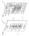
- FIG. 1is an exploded perspective view of an assembly according to the present invention with an outlet box.
- FIG. 2is a partially exploded perspective view of the assembly of FIG. 1 with the strap coupled to the outlet box.
- FIG. 3is a partially exploded perspective view of the assembly of FIG. 1 with the insert pieces mounted in the strap.
- FIG. 4is a front perspective view of the assembly of FIG. 1 .
- FIG. 5is a rear perspective view of the assembly of FIG. 1 .
- FIG. 6is a front perspective view of an assembly according to the present invention with connector modules mounted in the strap.
- FIG. 7is a rear perspective view of the assembly of FIG. 6 .
- FIG. 8is a front perspective view of a strap according to the present invention.
- FIG. 9is a rear perspective view of the strap of FIG. 8 .
- FIG. 10is a front view of the strap of FIG. 8 .
- FIG. 11is a rear view of the strap of FIG. 8 .
- FIG. 12is a side view of the strap of FIG. 8 .
- FIG. 13is a front perspective view of a blank insert piece according to the present invention.
- FIG. 14is a rear perspective view of the insert piece of FIG. 13 .
- FIG. 15is a front view of the insert piece of FIG. 13 .
- FIG. 16is rear view of the insert piece of FIG. 13 .
- FIG. 17is a top view of the insert piece of FIG. 13 .
- FIG. 18is a side view of the insert piece of FIG. 13 .
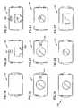
- FIG. 19is a front view of the insert of FIG. 13 .
- FIG. 20is a front view of an example of a computer data insert piece according to the present invention.
- FIG. 21is a front view of a telephone or voice insert piece according to the present invention.
- FIG. 22is a front view of a video IN insert piece according to the present invention.
- FIG. 23is a front view of a video OUT insert piece according to the present invention.
- FIG. 24is a front view of an RCA insert piece according to the present invention.
- FIG. 25is a front view of an S-video insert piece according to the present invention.
- FIG. 26is a front view of a fiber ST insert piece according to the present invention.
- FIG. 27is a front view of a fiber SC insert piece according to the present invention.
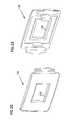
- FIG. 28is a front perspective view of the insert of FIG. 20 .
- FIG. 29is a rear perspective view of the insert of FIG. 20 .
- FIG. 30is a front perspective view of the insert of FIG. 22 .
- FIG. 31is a rear perspective view of the insert of FIG. 22 .
- FIG. 32is a front perspective view of the insert of FIG. 27 .
- FIG. 33is a rear perspective view of the insert of FIG. 27 .
- FIG. 34is a partial cross sectional front perspective view of the assembly of FIG. 6 along line A—A.
- FIG. 35is a rear perspective view of the assembly of FIG. 34 .
- FIG. 36is a cutaway perspective view of an assembly according to the present invention.
- FIGS. 1-5show a cover assembly 10 according to the present invention with an outlet box 20 .
- the assembly 10includes a cover plate 30 , insert pieces 40 , 41 , and 42 , and a strap 50 .
- Strap 50is configured to span an open end 55 of the outlet box 20 .
- the strap 50defines mounting apertures 53 for receiving connector modules 60 and 62 .
- Connector modules 60 and 62include cable connectors 56 or jacks 57 .
- Insert pieces 40 , 41 , and 42fit within a cover aperture 68 defined by the cover plate 30 .
- the cover plate 30holds the insert pieces against the strap 50 .
- the insert pieces 40 , 41 , and 42define connector apertures 40 ′, 41 ′, and 42 ′ for receiving connectors 56 mounted in the connector modules 60 or for receiving a connector into the jack 57 in connector module 62 .
- FIGS. 6 and 7show assembly 10 with the outlet box removed.
- the connector modules 60 and 62are snap-fit modules which include flexible push tabs 64 having a ramped lip 64 ′. Modules 60 and 62 may be inserted and removed from a frontside of the strap 50 by depressing the push tabs 64 .
- the connector module 60is shown to be engaged to the strap 50 .
- a portion of the strap 50is shown with phantom lines for clarity purposes to illustrate the ramped lip 64 ′ of the flexible push tab 64 of the connector module 60 engaged to the strap 50 .
- Screws 70couple the strap 50 to the cover plate 30 through fastener holes 72 and 74 defined by the cover plate and the strap 50 .
- the insert pieces 40 - 42overlap at least a portion of corresponding mounting apertures 53 in the strap 50 .
- the insert pieces 40 - 42prevent modules 60 and 62 from being removed from the strap 50 without first removing the cover plate 30 and insert pieces. Furthermore, the insert pieces themselves cannot be removed unless the cover plate 30 is first removed from the assembly 10 .
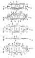
- FIGS. 8-12illustrate a strap 50 according to the present invention.
- the strap 50defines a plurality of mounting apertures 53 for mounting connector modules 60 to the outlet box 20 .
- the strap 50has a front surface 80 , a back surface 82 , and an outside edge 81 which includes two sides 83 and 84 .
- the outside edge 81is recessed from the front surface 80 , thereby forming a lip 85 around the outside edge of the strap 50 .
- the front surface 80 of the strap 50fits within the cover aperture 68 from a back side 33 of the cover plate 30 so that the lip 85 of the strap 50 abuts the back side 33 of the cover plate 30 .
- sides 83 and 84 of the strap 50define recessed shelves 90 .
- the shelves 90are shaped to receive side retention members 100 of the insert pieces 40 - 42 .
- Strap 50may also define tab slots 92 in the front surface 80 for receiving tabs 102 of the insert pieces.
- the strap 50defines fastener holes 74 for securing the strap 50 to the cover plate 30 .
- the strap 50also defines fastener holes 76 for securing the strap 50 to an outlet box 20 .
- FIGS. 13-18show a blank insert piece 110 according to the present invention.
- Each insert piece in the assembly 10corresponds to one or more mounting apertures 53 in the strap 50 .
- the insert piecescover the mounting apertures 53 and the connector modules 60 received in the mounting apertures 53 so that the modules 60 cannot be removed without first removing the insert pieces.
- Blank insert piece 110may be used as a dust cap to cover an unused jack to prevent dust or other foreign material from entering the jack or may be used to cover an empty mounting aperture.
- FIGS. 20-33include connector apertures for receiving a cable connector mounted in a mounting aperture 53 of the strap 50 to pass through the insert member or for allowing a connector on an end of a cable to be received by a jack under the insert piece.
- the connector aperturesmay be sized and shaped to correspond to various types of connectors or jacks.
- FIGS. 20 and 21show insert pieces 40 and 125 having a twisted pair plug aperture 126 .
- FIGS. 22 and 23show insert pieces 41 and 42 having a video connector aperture 124 .
- FIG. 24shows an insert piece 128 having an RCA connector aperture 129 .
- FIGS. 25-27show insert pieces 130 - 132 having other variously shaped connector apertures 133 - 135 . Other shapes can be used as desired for different connector styles.
- the insert piecesmay also include designation figures which identify the different applications using a connector or jack in the corresponding mounting aperture 53 .
- the insert piece 40 shown in FIGS. 20 and 28shows a computer figure 47 which may be used to designate that insert piece 40 corresponds to a computer data jack or port.
- insert pieces 125 , 41 and 42include designation figures. 140 , 141 , and 142 indicating telephone, video IN, and video OUT connectors or jacks respectively.
- the insert piecesmay also be color coded in order to differentiate between connector and jack types.
- an insert piece according to the present inventionsuch as insert piece 110 includes a middle member 112 having front and rear surfaces 205 and 206 .
- the front surface 205is shaped to correspond to the shape of a front surface 31 of the cover plate 30 .
- the front surface 205 of the insert pieceis curved to follow the curved front surface 31 of the cover plate 30 .
- the insert piece 110includes retention members 100 extending from opposed sides of the middle member 112 .
- the retention members 100have a front surface 210 which is set back from the front surface 205 of the middle member 112 of the insert piece 110 thereby forming a shoulder.
- the retention members 100are received by the shelves 90 of the strap 50 so that the retention members 100 are retained between a back side 33 of the cover plate 30 and the strap 50 .
- an aperture edge 35which defines the plate aperture 68 traps the retention members 100 of the insert piece 110 into opposed shelves 90 of the strap 50 .
- a back side 36 of the aperture edge 35abuts the front surface 210 of the retention members 100 .
- the insert pieces 40 - 42cannot be removed from the assembly without first removing the cover plate 30 .
- the cover plate 30prevents the removal of the insert pieces.
- the insert piecesprevent the modules 60 and 62 from being removed from the assembly.
- the insert piecesmay also include tabs 102 extending from the rear surface 206 of the middle member 112 .
- the insert tabs 102are sized to be received by the tab slots 92 defined by the strap 50 .
- the tabs 102may be configured to wedge or friction fit into tab slots 92 so that the frictional force of the tabs 102 in the tab slots 92 will hold the insert pieces in a mating arrangement with strap 50 during assembly. Insert tabs 102 assist in aligning the insert piece relative to the strap 50 and improve the ease of assembly.
- the retention members 100may also include extensions 211 . As shown in FIG. 35, when the insert members are assembled with the strap 50 the extensions 211 extend beyond side edges 213 of the strap 50 .
- the extension members 211provide a surface for easy removal of the insert pieces from the strap 50 .
- the insert piecesmay also include an orientation tab 240 .
- Orientation tab 240extends from the rear surface 206 of the insert piece 130 .
- Insert piece 130is an s-video insert piece which includes a slightly off-center connector aperture 133 .
- the orientation tab 240has been included. The orientation tab 240 is received by the connector module 260 above the push tab 64 and adjacent module portion 261 . If a user attempted to insert the insert piece up-side-down, the orientation tab 240 would be blocked by module portion 262 .
- the insert pieces of the present inventionmay be used to designate the various connectors and connector jacks in a multimedia outlet and may be swapped in and out of an outlet assembly as desired, but only upon prior removal of the cover plate 30 . In this way the insert pieces also prevent the snap-fit connector modules from being removed from the outlet without first removing the cover plate.
Landscapes
- Connector Housings Or Holding Contact Members (AREA)
Abstract
Description
Claims (35)
Priority Applications (2)
| Application Number | Priority Date | Filing Date | Title |
|---|---|---|---|
| US09/823,234US6793524B2 (en) | 2001-03-30 | 2001-03-30 | Multimedia outlet with protective cover |
| PCT/US2002/010006WO2002080310A1 (en) | 2001-03-30 | 2002-03-29 | Multimedia outlet with protective cover |
Applications Claiming Priority (1)
| Application Number | Priority Date | Filing Date | Title |
|---|---|---|---|
| US09/823,234US6793524B2 (en) | 2001-03-30 | 2001-03-30 | Multimedia outlet with protective cover |
Publications (2)
| Publication Number | Publication Date |
|---|---|
| US20020142650A1 US20020142650A1 (en) | 2002-10-03 |
| US6793524B2true US6793524B2 (en) | 2004-09-21 |
Family
ID=25238165
Family Applications (1)
| Application Number | Title | Priority Date | Filing Date |
|---|---|---|---|
| US09/823,234Expired - LifetimeUS6793524B2 (en) | 2001-03-30 | 2001-03-30 | Multimedia outlet with protective cover |
Country Status (2)
| Country | Link |
|---|---|
| US (1) | US6793524B2 (en) |
| WO (1) | WO2002080310A1 (en) |
Cited By (42)
| Publication number | Priority date | Publication date | Assignee | Title |
|---|---|---|---|---|
| US20060019533A1 (en)* | 2004-07-23 | 2006-01-26 | Yuan-Huei Peng | Bezel of modular jack |
| US20060134971A1 (en)* | 2004-12-17 | 2006-06-22 | Byrne Norman R | Voice/data adapter kit |
| US20060185877A1 (en)* | 2005-02-18 | 2006-08-24 | Aviv Soffer | Wall mounted system with insertable computing apparatus |
| US20060185878A1 (en)* | 2005-02-18 | 2006-08-24 | Aviv Soffer | Wall mounted housing for insertable computing apparatus |
| USD532288S1 (en)* | 2005-08-19 | 2006-11-21 | Leviton Manufacturing Co., Inc. | Two port wall plate insert |
| USD532678S1 (en)* | 2005-08-19 | 2006-11-28 | Leviton Manufacturing Co., Inc. | Three port wall plate insert |
| USD539118S1 (en)* | 2005-08-19 | 2007-03-27 | Leviton Manufacturing Co., Inc. | Six port wall plate insert |
| USD539119S1 (en)* | 2005-08-19 | 2007-03-27 | Leviton Manufacturing Co., Inc. | Four port wall plate insert |
| US20070161295A1 (en)* | 2006-01-06 | 2007-07-12 | Hammond Bernard H Jr | Methods and systems for minimizing alien crosstalk between connectors |
| US20070279887A1 (en)* | 2006-05-30 | 2007-12-06 | Thomas Sullivan | Wall plate assembly with integral digital extender |
| US7374454B1 (en)* | 2007-06-05 | 2008-05-20 | Sure-Fire Electrical Corporation | Wall plate assembly |
| US20080293293A1 (en)* | 2007-05-22 | 2008-11-27 | Thomas & Betts International, Inc. | Electrical outlet box face plate with adapter plate |
| US20090091898A1 (en)* | 2007-08-24 | 2009-04-09 | Todd Loeffelholz | Multimedia enclosure |
| US20090221179A1 (en)* | 2008-02-28 | 2009-09-03 | Arnel Berton Citurs | Tamper resistant faceplate system |
| US7820911B1 (en) | 2008-03-11 | 2010-10-26 | Arlington Industries, Inc. | Reversible protective cable chute assembly for routing low voltage cables through walls |
| US7834267B1 (en) | 2008-03-11 | 2010-11-16 | Arlington Industries, Inc. | Reversible protective cable chute with cable shield and integral cover plate |
| US7847190B1 (en) | 2008-01-24 | 2010-12-07 | Arlington Industries, Inc. | Reversible protective cable chute for routing low voltage cables through walls |
| US20100317223A1 (en)* | 2009-06-15 | 2010-12-16 | Byrne Norman R | Power and data adapter assembly |
| US7897870B1 (en) | 2008-01-24 | 2011-03-01 | Arlington Industries, Inc. | Cable routing assembly including low voltage bracket and scoop |
| US20110068103A1 (en)* | 2009-09-21 | 2011-03-24 | Electronic Custom Distributors, Inc. | Method and system of a reversible nose faceplate |
| US8067703B1 (en) | 2009-06-18 | 2011-11-29 | Arlington Industries, Inc. | Protective cable frame for use with low voltage bracket or electrical box |
| US8072779B1 (en)* | 2009-01-07 | 2011-12-06 | Pass & Seymour, Inc. | Recessed electrical device housing assembly and clip |
| US8124873B1 (en)* | 2009-06-18 | 2012-02-28 | Arlington Industries, Inc. | Cable routing assembly including protective cable frame |
| US20120115355A1 (en)* | 2009-05-20 | 2012-05-10 | Epcos Ag | Appliance installation device and method for producing the same |
| US20120222896A1 (en)* | 2009-01-07 | 2012-09-06 | Pass & Seymour, Inc. | Modular device housing assembly |
| US8382514B1 (en)* | 2012-08-24 | 2013-02-26 | Extreme Broadband Engineering, Llc | Wall plate/cover housing assembly |
| US8480429B2 (en) | 2005-06-13 | 2013-07-09 | Norman R. Byrne | Power data housing |
| US20130192868A1 (en)* | 2012-01-30 | 2013-08-01 | Panduit Corp. | Faceplate Assemblies For Securing Connectivity |
| US20130277086A1 (en)* | 2012-04-19 | 2013-10-24 | Pass & Seymour, Inc. | Modular electrical wiring device system |
| US20140068983A1 (en)* | 2012-09-12 | 2014-03-13 | Panduit Corp. | Flex Mount Terminal Marker |
| US20140179157A1 (en)* | 2009-04-15 | 2014-06-26 | Jair Gonzalez | Devices for mounting electrical, audio, and video installations to walls and other flat surfaces |
| US9058752B2 (en) | 2012-09-12 | 2015-06-16 | Panduit Corp. | Flex mount terminal marker |
| US9223336B2 (en) | 2011-05-17 | 2015-12-29 | 3M Innovative Properties Company | Remote socket apparatus |
| USD751514S1 (en)* | 2014-05-28 | 2016-03-15 | Sound Around, Inc. | USB wall plate with volume control |
| US20160276779A1 (en)* | 2015-03-18 | 2016-09-22 | Leviton Manufacturing Co., Inc. | Data Communication Port Insert Configurable with Indicia to Customize Data Communication Station Labeling and Identification |
| US20170054231A1 (en)* | 2015-08-21 | 2017-02-23 | Panduit Corp. | Terminal Block Marker |
| US9853401B2 (en)* | 2013-12-18 | 2017-12-26 | Hubbell Incorporated | Single-fastener mounting plate for electrical outlets |
| US20190229458A1 (en)* | 2018-01-24 | 2019-07-25 | Norman R. Byrne | Electrical power and data unit |
| US11445626B2 (en)* | 2017-06-10 | 2022-09-13 | Hesam Shemirani | Power outlet module including USB plug in location other than outlet face |
| US12176694B2 (en) | 2021-10-15 | 2024-12-24 | Norman R. Byrne | Electrical outlet assembly |
| US12186241B2 (en) | 2021-01-22 | 2025-01-07 | Hill-Rom Services, Inc. | Time-based wireless pairing between a medical device and a wall unit |
| US12279999B2 (en) | 2021-01-22 | 2025-04-22 | Hill-Rom Services, Inc. | Wireless configuration and authorization of a wall unit that pairs with a medical device |
Families Citing this family (18)
| Publication number | Priority date | Publication date | Assignee | Title |
|---|---|---|---|---|
| WO2005022692A2 (en) | 2003-08-21 | 2005-03-10 | Hill-Rom Services, Inc. | Plug and receptacle having wired and wireless coupling |
| EP1544961B1 (en)* | 2003-12-17 | 2013-11-27 | Byrne Electrical Specialists, Inc. | Voice/data adapter kit |
| US7884735B2 (en) | 2005-02-11 | 2011-02-08 | Hill-Rom Services, Inc. | Transferable patient care equipment support |
| US7563131B2 (en)* | 2005-08-12 | 2009-07-21 | Lastar, Inc. | Integrated wall plate assembly and premise wiring system incorporating the same |
| US7396254B2 (en)* | 2006-05-15 | 2008-07-08 | Deere & Company | Flexible electrical connector/housing assembly |
| GR1005926B (en)* | 2007-02-02 | 2008-05-27 | Γεωργιος Βασιλειου Τομαροπουλος | Rotary multi-socket cylinder or sphere. |
| US20080265082A1 (en)* | 2007-04-26 | 2008-10-30 | Joseph Angiuli | Retractable ID badge holder kit |
| US7637772B2 (en)* | 2007-10-19 | 2009-12-29 | Sure-Fire Electrical Corporation | Wall plate assembly |
| CN201797102U (en)* | 2010-09-01 | 2011-04-13 | 富士康(昆山)电脑接插件有限公司 | socket panel |
| CN201797132U (en)* | 2010-09-01 | 2011-04-13 | 富士康(昆山)电脑接插件有限公司 | socket panel |
| CN201797131U (en)* | 2010-09-01 | 2011-04-13 | 富士康(昆山)电脑接插件有限公司 | socket panel |
| US9172199B2 (en) | 2013-03-07 | 2015-10-27 | Heathco, Llc | Electrical fixture secured to a junction box via a cover plate having an electrical connector |
| US9246317B2 (en)* | 2013-04-02 | 2016-01-26 | Norman R. Byrne | Electrical receptacle with frames for mounting in a support |
| DE102013108487A1 (en)* | 2013-08-06 | 2015-02-12 | Günther Spelsberg GmbH & Co. KG | Electrical installation housing |
| CN105071101A (en)* | 2015-07-31 | 2015-11-18 | 常州嘉诚数码科技有限公司 | Automobile connector with secondary sealing protection devices |
| US10395769B2 (en) | 2015-12-16 | 2019-08-27 | Hill-Rom Services, Inc. | Patient care devices with local indication of correspondence and power line interconnectivity |
| US11411377B2 (en)* | 2020-01-10 | 2022-08-09 | Commscope Technologies Llc | Connection interface |
| US12051881B2 (en)* | 2021-03-08 | 2024-07-30 | Samtec, Inc. | Connector with linear coaxial, right angle coaxial and optical connectors |
Citations (18)
| Publication number | Priority date | Publication date | Assignee | Title |
|---|---|---|---|---|
| US1930610A (en) | 1933-02-20 | 1933-10-17 | Pass & Seymour Inc | Card holder |
| US3494244A (en)* | 1967-10-24 | 1970-02-10 | Wasco Inc | Fastener |
| US3921798A (en) | 1974-05-06 | 1975-11-25 | Wright Barry Corp | Cartridge label holder |
| DE8708237U1 (en) | 1987-06-11 | 1987-08-06 | A. & H. Meyer GmbH Leuchten und Büroelektrik, 32694 Dörentrup | Socket box |
| US4756695A (en)* | 1986-06-13 | 1988-07-12 | Amp Incorporated | Local area network interface |
| US4835343A (en)* | 1987-03-30 | 1989-05-30 | Lutron Electronics Co., Inc. | Two piece face plate for wall box mounted device |
| US4875880A (en)* | 1988-07-21 | 1989-10-24 | Digital Equipment Corporation | Modular faceplate system |
| US5457286A (en)* | 1991-12-13 | 1995-10-10 | Flasz; Igor | Face plate assembly for electrical receptacle |
| US5484307A (en)* | 1987-02-06 | 1996-01-16 | Leviton Manufacturing Co., Inc. | Flush mounted telephone jack |
| US5575100A (en) | 1994-06-23 | 1996-11-19 | At&T Global Information Solutions Company | Electronic shelf label protective cover |
| US5613874A (en) | 1995-05-05 | 1997-03-25 | Ortronics Inc. | Snap-in designation strip for modular information management oulet |
| US5708705A (en) | 1994-04-28 | 1998-01-13 | Nec Corporation | Wallhung arrangement for a cordless telephone |
| US5744750A (en)* | 1994-11-30 | 1998-04-28 | R123 Enterprises Ltd. | Modular electrical connector box |
| US5775935A (en)* | 1996-12-18 | 1998-07-07 | Computer Data Exchange, Inc. | System and method for connecting color coded cables to a device |
| US5862616A (en) | 1996-06-24 | 1999-01-26 | Lafrance Corp. | Locking plate |
| US5933994A (en) | 1997-06-19 | 1999-08-10 | Russell & Miller, Inc. | Retail checkout divider adapted to receive strips with indicia displayed thereon |
| US5961345A (en) | 1998-01-14 | 1999-10-05 | Cabletron Systems, Inc. | Faceplate system |
| US6056593A (en)* | 1997-03-26 | 2000-05-02 | Hubbell Incorporated | Electrical receptacle assembly having housing held together by front mounting bridge |
- 2001
- 2001-03-30USUS09/823,234patent/US6793524B2/ennot_activeExpired - Lifetime
- 2002
- 2002-03-29WOPCT/US2002/010006patent/WO2002080310A1/ennot_activeApplication Discontinuation
Patent Citations (18)
| Publication number | Priority date | Publication date | Assignee | Title |
|---|---|---|---|---|
| US1930610A (en) | 1933-02-20 | 1933-10-17 | Pass & Seymour Inc | Card holder |
| US3494244A (en)* | 1967-10-24 | 1970-02-10 | Wasco Inc | Fastener |
| US3921798A (en) | 1974-05-06 | 1975-11-25 | Wright Barry Corp | Cartridge label holder |
| US4756695A (en)* | 1986-06-13 | 1988-07-12 | Amp Incorporated | Local area network interface |
| US5484307A (en)* | 1987-02-06 | 1996-01-16 | Leviton Manufacturing Co., Inc. | Flush mounted telephone jack |
| US4835343A (en)* | 1987-03-30 | 1989-05-30 | Lutron Electronics Co., Inc. | Two piece face plate for wall box mounted device |
| DE8708237U1 (en) | 1987-06-11 | 1987-08-06 | A. & H. Meyer GmbH Leuchten und Büroelektrik, 32694 Dörentrup | Socket box |
| US4875880A (en)* | 1988-07-21 | 1989-10-24 | Digital Equipment Corporation | Modular faceplate system |
| US5457286A (en)* | 1991-12-13 | 1995-10-10 | Flasz; Igor | Face plate assembly for electrical receptacle |
| US5708705A (en) | 1994-04-28 | 1998-01-13 | Nec Corporation | Wallhung arrangement for a cordless telephone |
| US5575100A (en) | 1994-06-23 | 1996-11-19 | At&T Global Information Solutions Company | Electronic shelf label protective cover |
| US5744750A (en)* | 1994-11-30 | 1998-04-28 | R123 Enterprises Ltd. | Modular electrical connector box |
| US5613874A (en) | 1995-05-05 | 1997-03-25 | Ortronics Inc. | Snap-in designation strip for modular information management oulet |
| US5862616A (en) | 1996-06-24 | 1999-01-26 | Lafrance Corp. | Locking plate |
| US5775935A (en)* | 1996-12-18 | 1998-07-07 | Computer Data Exchange, Inc. | System and method for connecting color coded cables to a device |
| US6056593A (en)* | 1997-03-26 | 2000-05-02 | Hubbell Incorporated | Electrical receptacle assembly having housing held together by front mounting bridge |
| US5933994A (en) | 1997-06-19 | 1999-08-10 | Russell & Miller, Inc. | Retail checkout divider adapted to receive strips with indicia displayed thereon |
| US5961345A (en) | 1998-01-14 | 1999-10-05 | Cabletron Systems, Inc. | Faceplate system |
Non-Patent Citations (4)
| Title |
|---|
| ADC Telecommunications Enteraprise Catalog for 5000E and 3000 Multimedia Outlets dated Apr. 1999. |
| ADC Telecommunications Enteraprise Catalog of Patch Panels dated Dec. 2000. |
| Exhibit A, Photographs of bezel corresponding to bezels shown in Dec. 2000 ADC catalog referenced above. |
| The Siemon Company Catalog, pp. 120-121 (1997). |
Cited By (62)
| Publication number | Priority date | Publication date | Assignee | Title |
|---|---|---|---|---|
| US7131864B2 (en)* | 2004-07-23 | 2006-11-07 | Yuan-Huei Peng | Bezel of modular jack |
| US20060019533A1 (en)* | 2004-07-23 | 2006-01-26 | Yuan-Huei Peng | Bezel of modular jack |
| US20060134971A1 (en)* | 2004-12-17 | 2006-06-22 | Byrne Norman R | Voice/data adapter kit |
| US7182633B2 (en)* | 2004-12-17 | 2007-02-27 | Byrne Norman R | Voice/data adapter kit |
| US20060185877A1 (en)* | 2005-02-18 | 2006-08-24 | Aviv Soffer | Wall mounted system with insertable computing apparatus |
| US20060185878A1 (en)* | 2005-02-18 | 2006-08-24 | Aviv Soffer | Wall mounted housing for insertable computing apparatus |
| US20100157524A1 (en)* | 2005-02-18 | 2010-06-24 | Chip Pc Israel Ltd. | Wall mounted system with insertable computing apparatus |
| US8158883B2 (en)* | 2005-02-18 | 2012-04-17 | Chip Pc Israel Ltd. | Wall mounted system with insertable computing apparatus |
| US8480429B2 (en) | 2005-06-13 | 2013-07-09 | Norman R. Byrne | Power data housing |
| USD532678S1 (en)* | 2005-08-19 | 2006-11-28 | Leviton Manufacturing Co., Inc. | Three port wall plate insert |
| USD539119S1 (en)* | 2005-08-19 | 2007-03-27 | Leviton Manufacturing Co., Inc. | Four port wall plate insert |
| USD539118S1 (en)* | 2005-08-19 | 2007-03-27 | Leviton Manufacturing Co., Inc. | Six port wall plate insert |
| USD532288S1 (en)* | 2005-08-19 | 2006-11-21 | Leviton Manufacturing Co., Inc. | Two port wall plate insert |
| US20070161295A1 (en)* | 2006-01-06 | 2007-07-12 | Hammond Bernard H Jr | Methods and systems for minimizing alien crosstalk between connectors |
| US7771230B2 (en) | 2006-01-06 | 2010-08-10 | Adc Telecommunications, Inc. | Methods and systems for minimizing alien crosstalk between connectors |
| US7294024B2 (en) | 2006-01-06 | 2007-11-13 | Adc Telecommunications, Inc. | Methods and systems for minimizing alien crosstalk between connectors |
| US20070279887A1 (en)* | 2006-05-30 | 2007-12-06 | Thomas Sullivan | Wall plate assembly with integral digital extender |
| US20080293293A1 (en)* | 2007-05-22 | 2008-11-27 | Thomas & Betts International, Inc. | Electrical outlet box face plate with adapter plate |
| US7622676B2 (en) | 2007-05-22 | 2009-11-24 | Thomas & Betts International, Inc. | Electrical outlet box face plate with adapter plate |
| US7374454B1 (en)* | 2007-06-05 | 2008-05-20 | Sure-Fire Electrical Corporation | Wall plate assembly |
| US20090091898A1 (en)* | 2007-08-24 | 2009-04-09 | Todd Loeffelholz | Multimedia enclosure |
| US8081482B2 (en) | 2007-08-24 | 2011-12-20 | Adc Telecommunications, Inc. | Multimedia enclosure |
| US7897870B1 (en) | 2008-01-24 | 2011-03-01 | Arlington Industries, Inc. | Cable routing assembly including low voltage bracket and scoop |
| US7847190B1 (en) | 2008-01-24 | 2010-12-07 | Arlington Industries, Inc. | Reversible protective cable chute for routing low voltage cables through walls |
| US20090221179A1 (en)* | 2008-02-28 | 2009-09-03 | Arnel Berton Citurs | Tamper resistant faceplate system |
| US7834267B1 (en) | 2008-03-11 | 2010-11-16 | Arlington Industries, Inc. | Reversible protective cable chute with cable shield and integral cover plate |
| US7820911B1 (en) | 2008-03-11 | 2010-10-26 | Arlington Industries, Inc. | Reversible protective cable chute assembly for routing low voltage cables through walls |
| US20120222896A1 (en)* | 2009-01-07 | 2012-09-06 | Pass & Seymour, Inc. | Modular device housing assembly |
| US8921714B2 (en)* | 2009-01-07 | 2014-12-30 | Pass & Seymour, Inc. | Modular device housing assembly |
| US8072779B1 (en)* | 2009-01-07 | 2011-12-06 | Pass & Seymour, Inc. | Recessed electrical device housing assembly and clip |
| US9419422B2 (en)* | 2009-04-15 | 2016-08-16 | Flatrim Llc | Devices for mounting electrical, audio, and video installations to walls and other flat surfaces |
| US20140179157A1 (en)* | 2009-04-15 | 2014-06-26 | Jair Gonzalez | Devices for mounting electrical, audio, and video installations to walls and other flat surfaces |
| US20120115355A1 (en)* | 2009-05-20 | 2012-05-10 | Epcos Ag | Appliance installation device and method for producing the same |
| US20100317223A1 (en)* | 2009-06-15 | 2010-12-16 | Byrne Norman R | Power and data adapter assembly |
| US8444432B2 (en) | 2009-06-15 | 2013-05-21 | Norman R. Byrne | Power and data adapter assembly |
| US8067703B1 (en) | 2009-06-18 | 2011-11-29 | Arlington Industries, Inc. | Protective cable frame for use with low voltage bracket or electrical box |
| US8124873B1 (en)* | 2009-06-18 | 2012-02-28 | Arlington Industries, Inc. | Cable routing assembly including protective cable frame |
| US20110068103A1 (en)* | 2009-09-21 | 2011-03-24 | Electronic Custom Distributors, Inc. | Method and system of a reversible nose faceplate |
| US8490815B2 (en) | 2009-09-21 | 2013-07-23 | DirectConnect | Method and system of a reversible nose faceplate |
| US9223336B2 (en) | 2011-05-17 | 2015-12-29 | 3M Innovative Properties Company | Remote socket apparatus |
| US20130192868A1 (en)* | 2012-01-30 | 2013-08-01 | Panduit Corp. | Faceplate Assemblies For Securing Connectivity |
| US10297995B2 (en) | 2012-04-19 | 2019-05-21 | Pass & Seymour, Inc. | Protective electrical device |
| US12300955B2 (en)* | 2012-04-19 | 2025-05-13 | Pass & Seymour, Inc. | Method of manufacturing a modular electrical wiring device system |
| US20130277086A1 (en)* | 2012-04-19 | 2013-10-24 | Pass & Seymour, Inc. | Modular electrical wiring device system |
| US9301410B2 (en)* | 2012-04-19 | 2016-03-29 | Pass & Seymour, Inc. | Modular electrical wiring device system |
| US8382514B1 (en)* | 2012-08-24 | 2013-02-26 | Extreme Broadband Engineering, Llc | Wall plate/cover housing assembly |
| US8857086B2 (en)* | 2012-09-12 | 2014-10-14 | Panduit Corp. | Flex mount terminal marker |
| US9058752B2 (en) | 2012-09-12 | 2015-06-16 | Panduit Corp. | Flex mount terminal marker |
| US20140068983A1 (en)* | 2012-09-12 | 2014-03-13 | Panduit Corp. | Flex Mount Terminal Marker |
| US9853401B2 (en)* | 2013-12-18 | 2017-12-26 | Hubbell Incorporated | Single-fastener mounting plate for electrical outlets |
| US10177510B2 (en) | 2013-12-18 | 2019-01-08 | Hubbell Incorporated | Single-fastener mounting plate for electrical outlets |
| USD751514S1 (en)* | 2014-05-28 | 2016-03-15 | Sound Around, Inc. | USB wall plate with volume control |
| US10151890B2 (en)* | 2015-03-18 | 2018-12-11 | Leviton Manufacturing Co., Inc. | Data communication port insert configurable with indicia to customize data communication station labeling and identification |
| US20160276779A1 (en)* | 2015-03-18 | 2016-09-22 | Leviton Manufacturing Co., Inc. | Data Communication Port Insert Configurable with Indicia to Customize Data Communication Station Labeling and Identification |
| US10062979B2 (en)* | 2015-08-21 | 2018-08-28 | Panduit Corp. | Terminal block marker |
| US20170054231A1 (en)* | 2015-08-21 | 2017-02-23 | Panduit Corp. | Terminal Block Marker |
| US11445626B2 (en)* | 2017-06-10 | 2022-09-13 | Hesam Shemirani | Power outlet module including USB plug in location other than outlet face |
| US20190229458A1 (en)* | 2018-01-24 | 2019-07-25 | Norman R. Byrne | Electrical power and data unit |
| US10811809B2 (en)* | 2018-01-24 | 2020-10-20 | Norman R. Byrne | Electrical power and data unit |
| US12186241B2 (en) | 2021-01-22 | 2025-01-07 | Hill-Rom Services, Inc. | Time-based wireless pairing between a medical device and a wall unit |
| US12279999B2 (en) | 2021-01-22 | 2025-04-22 | Hill-Rom Services, Inc. | Wireless configuration and authorization of a wall unit that pairs with a medical device |
| US12176694B2 (en) | 2021-10-15 | 2024-12-24 | Norman R. Byrne | Electrical outlet assembly |
Also Published As
| Publication number | Publication date |
|---|---|
| US20020142650A1 (en) | 2002-10-03 |
| WO2002080310A1 (en) | 2002-10-10 |
Similar Documents
| Publication | Publication Date | Title |
|---|---|---|
| US6793524B2 (en) | Multimedia outlet with protective cover | |
| US11579391B2 (en) | Fiber optic splitter module | |
| US9784928B2 (en) | Fiber optic connector holder and method | |
| EP1883844B1 (en) | Fiber optic adapter module consisting of plurality of integrally formed adapters | |
| US5217190A (en) | Panel yoke | |
| US7488205B2 (en) | Fixed angled patch panel | |
| US8520997B2 (en) | Fiber optic splitter module | |
| US7361052B2 (en) | Multimedia outlet box | |
| KR100245143B1 (en) | Double connector with anti-snacks | |
| US4875881A (en) | Communication box assembly | |
| US7343078B2 (en) | Patch panels with communications connectors that are rotatable about a vertical axis | |
| US9832542B2 (en) | Patch panel system and jack module attachment thereto | |
| US20030113086A1 (en) | Optical splitter module | |
| US8290332B2 (en) | Optical fiber adapter | |
| US5143868A (en) | Communication box assembly | |
| US6741783B2 (en) | Optical cable adapter or connector | |
| US6206580B1 (en) | Optical connector | |
| US5013260A (en) | Communication box assembly | |
| US6042419A (en) | Securing device for a jack | |
| US4950184A (en) | Wall plate assembly | |
| US5383096A (en) | I/O expansion box | |
| US20230102638A1 (en) | Termination box | |
| KR200359596Y1 (en) | Wall outlet for a fiber optic connector assembly | |
| AU2012265621B2 (en) | Fiber optic splitter module | |
| US20030123811A1 (en) | Connector receptacle |
Legal Events
| Date | Code | Title | Description |
|---|---|---|---|
| AS | Assignment | Owner name:ADC TELECOMMUNICATIONS, INC., MINNESOTA Free format text:ASSIGNMENT OF ASSIGNORS INTEREST;ASSIGNORS:CLARK, GORDON P.;COPPOCK, DAVID G.;MATTSON, LOREN J.;REEL/FRAME:012001/0688 Effective date:20010413 | |
| STCF | Information on status: patent grant | Free format text:PATENTED CASE | |
| FPAY | Fee payment | Year of fee payment:4 | |
| FPAY | Fee payment | Year of fee payment:8 | |
| AS | Assignment | Owner name:TYCO ELECTRONICS SERVICES GMBH, SWITZERLAND Free format text:ASSIGNMENT OF ASSIGNORS INTEREST;ASSIGNOR:ADC TELECOMMUNICATIONS, INC.;REEL/FRAME:036060/0174 Effective date:20110930 | |
| AS | Assignment | Owner name:COMMSCOPE EMEA LIMITED, IRELAND Free format text:ASSIGNMENT OF ASSIGNORS INTEREST;ASSIGNOR:TYCO ELECTRONICS SERVICES GMBH;REEL/FRAME:036956/0001 Effective date:20150828 | |
| AS | Assignment | Owner name:COMMSCOPE TECHNOLOGIES LLC, NORTH CAROLINA Free format text:ASSIGNMENT OF ASSIGNORS INTEREST;ASSIGNOR:COMMSCOPE EMEA LIMITED;REEL/FRAME:037012/0001 Effective date:20150828 | |
| AS | Assignment | Owner name:JPMORGAN CHASE BANK, N.A., AS COLLATERAL AGENT, ILLINOIS Free format text:PATENT SECURITY AGREEMENT (TERM);ASSIGNOR:COMMSCOPE TECHNOLOGIES LLC;REEL/FRAME:037513/0709 Effective date:20151220 Owner name:JPMORGAN CHASE BANK, N.A., AS COLLATERAL AGENT, ILLINOIS Free format text:PATENT SECURITY AGREEMENT (ABL);ASSIGNOR:COMMSCOPE TECHNOLOGIES LLC;REEL/FRAME:037514/0196 Effective date:20151220 Owner name:JPMORGAN CHASE BANK, N.A., AS COLLATERAL AGENT, IL Free format text:PATENT SECURITY AGREEMENT (ABL);ASSIGNOR:COMMSCOPE TECHNOLOGIES LLC;REEL/FRAME:037514/0196 Effective date:20151220 Owner name:JPMORGAN CHASE BANK, N.A., AS COLLATERAL AGENT, IL Free format text:PATENT SECURITY AGREEMENT (TERM);ASSIGNOR:COMMSCOPE TECHNOLOGIES LLC;REEL/FRAME:037513/0709 Effective date:20151220 | |
| FPAY | Fee payment | Year of fee payment:12 | |
| AS | Assignment | Owner name:COMMSCOPE, INC. OF NORTH CAROLINA, NORTH CAROLINA Free format text:RELEASE BY SECURED PARTY;ASSIGNOR:JPMORGAN CHASE BANK, N.A.;REEL/FRAME:048840/0001 Effective date:20190404 Owner name:ALLEN TELECOM LLC, ILLINOIS Free format text:RELEASE BY SECURED PARTY;ASSIGNOR:JPMORGAN CHASE BANK, N.A.;REEL/FRAME:048840/0001 Effective date:20190404 Owner name:COMMSCOPE TECHNOLOGIES LLC, NORTH CAROLINA Free format text:RELEASE BY SECURED PARTY;ASSIGNOR:JPMORGAN CHASE BANK, N.A.;REEL/FRAME:048840/0001 Effective date:20190404 Owner name:REDWOOD SYSTEMS, INC., NORTH CAROLINA Free format text:RELEASE BY SECURED PARTY;ASSIGNOR:JPMORGAN CHASE BANK, N.A.;REEL/FRAME:048840/0001 Effective date:20190404 Owner name:ANDREW LLC, NORTH CAROLINA Free format text:RELEASE BY SECURED PARTY;ASSIGNOR:JPMORGAN CHASE BANK, N.A.;REEL/FRAME:048840/0001 Effective date:20190404 Owner name:REDWOOD SYSTEMS, INC., NORTH CAROLINA Free format text:RELEASE BY SECURED PARTY;ASSIGNOR:JPMORGAN CHASE BANK, N.A.;REEL/FRAME:049260/0001 Effective date:20190404 Owner name:ANDREW LLC, NORTH CAROLINA Free format text:RELEASE BY SECURED PARTY;ASSIGNOR:JPMORGAN CHASE BANK, N.A.;REEL/FRAME:049260/0001 Effective date:20190404 Owner name:ALLEN TELECOM LLC, ILLINOIS Free format text:RELEASE BY SECURED PARTY;ASSIGNOR:JPMORGAN CHASE BANK, N.A.;REEL/FRAME:049260/0001 Effective date:20190404 Owner name:COMMSCOPE, INC. OF NORTH CAROLINA, NORTH CAROLINA Free format text:RELEASE BY SECURED PARTY;ASSIGNOR:JPMORGAN CHASE BANK, N.A.;REEL/FRAME:049260/0001 Effective date:20190404 Owner name:COMMSCOPE TECHNOLOGIES LLC, NORTH CAROLINA Free format text:RELEASE BY SECURED PARTY;ASSIGNOR:JPMORGAN CHASE BANK, N.A.;REEL/FRAME:049260/0001 Effective date:20190404 | |
| AS | Assignment | Owner name:WILMINGTON TRUST, NATIONAL ASSOCIATION, AS COLLATE Free format text:PATENT SECURITY AGREEMENT;ASSIGNOR:COMMSCOPE TECHNOLOGIES LLC;REEL/FRAME:049892/0051 Effective date:20190404 Owner name:JPMORGAN CHASE BANK, N.A., NEW YORK Free format text:ABL SECURITY AGREEMENT;ASSIGNORS:COMMSCOPE, INC. OF NORTH CAROLINA;COMMSCOPE TECHNOLOGIES LLC;ARRIS ENTERPRISES LLC;AND OTHERS;REEL/FRAME:049892/0396 Effective date:20190404 Owner name:JPMORGAN CHASE BANK, N.A., NEW YORK Free format text:TERM LOAN SECURITY AGREEMENT;ASSIGNORS:COMMSCOPE, INC. OF NORTH CAROLINA;COMMSCOPE TECHNOLOGIES LLC;ARRIS ENTERPRISES LLC;AND OTHERS;REEL/FRAME:049905/0504 Effective date:20190404 Owner name:WILMINGTON TRUST, NATIONAL ASSOCIATION, AS COLLATERAL AGENT, CONNECTICUT Free format text:PATENT SECURITY AGREEMENT;ASSIGNOR:COMMSCOPE TECHNOLOGIES LLC;REEL/FRAME:049892/0051 Effective date:20190404 | |
| AS | Assignment | Owner name:WILMINGTON TRUST, DELAWARE Free format text:SECURITY INTEREST;ASSIGNORS:ARRIS SOLUTIONS, INC.;ARRIS ENTERPRISES LLC;COMMSCOPE TECHNOLOGIES LLC;AND OTHERS;REEL/FRAME:060752/0001 Effective date:20211115 | |
| AS | Assignment | Owner name:RUCKUS WIRELESS, LLC (F/K/A RUCKUS WIRELESS, INC.), NORTH CAROLINA Free format text:RELEASE OF SECURITY INTEREST AT REEL/FRAME 049905/0504;ASSIGNOR:JPMORGAN CHASE BANK, N.A., AS COLLATERAL AGENT;REEL/FRAME:071477/0255 Effective date:20241217 Owner name:COMMSCOPE TECHNOLOGIES LLC, NORTH CAROLINA Free format text:RELEASE OF SECURITY INTEREST AT REEL/FRAME 049905/0504;ASSIGNOR:JPMORGAN CHASE BANK, N.A., AS COLLATERAL AGENT;REEL/FRAME:071477/0255 Effective date:20241217 Owner name:COMMSCOPE, INC. OF NORTH CAROLINA, NORTH CAROLINA Free format text:RELEASE OF SECURITY INTEREST AT REEL/FRAME 049905/0504;ASSIGNOR:JPMORGAN CHASE BANK, N.A., AS COLLATERAL AGENT;REEL/FRAME:071477/0255 Effective date:20241217 Owner name:ARRIS SOLUTIONS, INC., NORTH CAROLINA Free format text:RELEASE OF SECURITY INTEREST AT REEL/FRAME 049905/0504;ASSIGNOR:JPMORGAN CHASE BANK, N.A., AS COLLATERAL AGENT;REEL/FRAME:071477/0255 Effective date:20241217 Owner name:ARRIS TECHNOLOGY, INC., NORTH CAROLINA Free format text:RELEASE OF SECURITY INTEREST AT REEL/FRAME 049905/0504;ASSIGNOR:JPMORGAN CHASE BANK, N.A., AS COLLATERAL AGENT;REEL/FRAME:071477/0255 Effective date:20241217 Owner name:ARRIS ENTERPRISES LLC (F/K/A ARRIS ENTERPRISES, INC.), NORTH CAROLINA Free format text:RELEASE OF SECURITY INTEREST AT REEL/FRAME 049905/0504;ASSIGNOR:JPMORGAN CHASE BANK, N.A., AS COLLATERAL AGENT;REEL/FRAME:071477/0255 Effective date:20241217 |