US6792199B2 - Variable temperature vaporizer - Google Patents
Variable temperature vaporizerDownload PDFInfo
- Publication number
- US6792199B2 US6792199B2US10/462,558US46255803AUS6792199B2US 6792199 B2US6792199 B2US 6792199B2US 46255803 AUS46255803 AUS 46255803AUS 6792199 B2US6792199 B2US 6792199B2
- Authority
- US
- United States
- Prior art keywords
- heating element
- temperature
- wick
- vaporizer
- fragrance
- Prior art date
- Legal status (The legal status is an assumption and is not a legal conclusion. Google has not performed a legal analysis and makes no representation as to the accuracy of the status listed.)
- Expired - Lifetime
Links
- 239000006200vaporizerSubstances0.000titleabstractdescription47
- 238000010438heat treatmentMethods0.000claimsabstractdescription57
- 238000001704evaporationMethods0.000claimsabstractdescription17
- 230000008020evaporationEffects0.000claimsabstractdescription17
- 238000000034methodMethods0.000claimsabstractdescription9
- 239000000126substanceSubstances0.000claimsdescription15
- 239000012530fluidSubstances0.000claims1
- 239000003205fragranceSubstances0.000abstractdescription41
- 239000007788liquidSubstances0.000abstractdescription32
- 239000000463materialSubstances0.000description19
- 230000008016vaporizationEffects0.000description5
- 239000000835fiberSubstances0.000description4
- 239000004033plasticSubstances0.000description4
- 229920003023plasticPolymers0.000description4
- 241000255925DipteraSpecies0.000description3
- 239000004743PolypropyleneSubstances0.000description3
- 239000002386air freshenerSubstances0.000description3
- 238000013461designMethods0.000description3
- 230000000694effectsEffects0.000description3
- 239000002917insecticideSubstances0.000description3
- 239000011344liquid materialSubstances0.000description3
- -1polypropylenePolymers0.000description3
- 229920001155polypropylenePolymers0.000description3
- 239000004831Hot glueSubstances0.000description2
- 229920002302Nylon 6,6Polymers0.000description2
- 230000015572biosynthetic processEffects0.000description2
- 239000000919ceramicSubstances0.000description2
- 239000003795chemical substances by applicationSubstances0.000description2
- 239000000645desinfectantSubstances0.000description2
- 239000011521glassSubstances0.000description2
- 239000003365glass fiberSubstances0.000description2
- 229920001903high density polyethylenePolymers0.000description2
- 239000004700high-density polyethyleneSubstances0.000description2
- 239000000077insect repellentSubstances0.000description2
- 230000007246mechanismEffects0.000description2
- 239000000203mixtureSubstances0.000description2
- 238000012986modificationMethods0.000description2
- 230000004048modificationEffects0.000description2
- 238000000554physical therapyMethods0.000description2
- 230000008569processEffects0.000description2
- 238000011012sanitizationMethods0.000description2
- 238000009834vaporizationMethods0.000description2
- 239000002023woodSubstances0.000description2
- 229920001824Barex®Polymers0.000description1
- OKTJSMMVPCPJKN-UHFFFAOYSA-NCarbonChemical compound[C]OKTJSMMVPCPJKN-UHFFFAOYSA-N0.000description1
- 229920000049Carbon (fiber)Polymers0.000description1
- 239000000443aerosolSubstances0.000description1
- 238000013459approachMethods0.000description1
- 230000003190augmentative effectEffects0.000description1
- 230000009286beneficial effectEffects0.000description1
- 230000036760body temperatureEffects0.000description1
- 229910052799carbonInorganic materials0.000description1
- 239000004917carbon fiberSubstances0.000description1
- 229910010293ceramic materialInorganic materials0.000description1
- 239000002131composite materialSubstances0.000description1
- 230000003247decreasing effectEffects0.000description1
- 239000002781deodorant agentSubstances0.000description1
- 238000005265energy consumptionMethods0.000description1
- 230000004907fluxEffects0.000description1
- 239000007789gasSubstances0.000description1
- 239000000499gelSubstances0.000description1
- 230000005484gravityEffects0.000description1
- 230000006698inductionEffects0.000description1
- 230000014759maintenance of locationEffects0.000description1
- 238000004519manufacturing processMethods0.000description1
- 239000012528membraneSubstances0.000description1
- 239000002184metalSubstances0.000description1
- 230000005012migrationEffects0.000description1
- 238000013508migrationMethods0.000description1
- 239000003921oilSubstances0.000description1
- 238000013021overheatingMethods0.000description1
- 239000002245particleSubstances0.000description1
- 239000000825pharmaceutical preparationSubstances0.000description1
- 230000002265preventionEffects0.000description1
- 230000009467reductionEffects0.000description1
- 230000004044responseEffects0.000description1
- 239000004065semiconductorSubstances0.000description1
- 239000007787solidSubstances0.000description1
- 239000000243solutionSubstances0.000description1
- 239000004575stoneSubstances0.000description1
- XLYOFNOQVPJJNP-UHFFFAOYSA-NwaterSubstancesOXLYOFNOQVPJJNP-UHFFFAOYSA-N0.000description1
Images


Classifications
- A—HUMAN NECESSITIES
- A01—AGRICULTURE; FORESTRY; ANIMAL HUSBANDRY; HUNTING; TRAPPING; FISHING
- A01M—CATCHING, TRAPPING OR SCARING OF ANIMALS; APPARATUS FOR THE DESTRUCTION OF NOXIOUS ANIMALS OR NOXIOUS PLANTS
- A01M1/00—Stationary means for catching or killing insects
- A01M1/20—Poisoning, narcotising, or burning insects
- A01M1/2022—Poisoning or narcotising insects by vaporising an insecticide
- A01M1/2061—Poisoning or narcotising insects by vaporising an insecticide using a heat source
- A01M1/2077—Poisoning or narcotising insects by vaporising an insecticide using a heat source using an electrical resistance as heat source
- A—HUMAN NECESSITIES
- A61—MEDICAL OR VETERINARY SCIENCE; HYGIENE
- A61L—METHODS OR APPARATUS FOR STERILISING MATERIALS OR OBJECTS IN GENERAL; DISINFECTION, STERILISATION OR DEODORISATION OF AIR; CHEMICAL ASPECTS OF BANDAGES, DRESSINGS, ABSORBENT PADS OR SURGICAL ARTICLES; MATERIALS FOR BANDAGES, DRESSINGS, ABSORBENT PADS OR SURGICAL ARTICLES
- A61L9/00—Disinfection, sterilisation or deodorisation of air
- A61L9/015—Disinfection, sterilisation or deodorisation of air using gaseous or vaporous substances, e.g. ozone
- A61L9/02—Disinfection, sterilisation or deodorisation of air using gaseous or vaporous substances, e.g. ozone using substances evaporated in the air by heating or combustion
- A61L9/03—Apparatus therefor
- A61L9/037—Apparatus therefor comprising a wick
- F—MECHANICAL ENGINEERING; LIGHTING; HEATING; WEAPONS; BLASTING
- F24—HEATING; RANGES; VENTILATING
- F24F—AIR-CONDITIONING; AIR-HUMIDIFICATION; VENTILATION; USE OF AIR CURRENTS FOR SCREENING
- F24F6/00—Air-humidification, e.g. cooling by humidification
- F24F6/02—Air-humidification, e.g. cooling by humidification by evaporation of water in the air
- F24F6/08—Air-humidification, e.g. cooling by humidification by evaporation of water in the air using heated wet elements
- F24F6/10—Air-humidification, e.g. cooling by humidification by evaporation of water in the air using heated wet elements heated electrically
- H—ELECTRICITY
- H05—ELECTRIC TECHNIQUES NOT OTHERWISE PROVIDED FOR
- H05B—ELECTRIC HEATING; ELECTRIC LIGHT SOURCES NOT OTHERWISE PROVIDED FOR; CIRCUIT ARRANGEMENTS FOR ELECTRIC LIGHT SOURCES, IN GENERAL
- H05B1/00—Details of electric heating devices
- H05B1/02—Automatic switching arrangements specially adapted to apparatus ; Control of heating devices
- H05B1/0227—Applications
- H05B1/023—Industrial applications
- H05B1/0244—Heating of fluids
- H—ELECTRICITY
- H05—ELECTRIC TECHNIQUES NOT OTHERWISE PROVIDED FOR
- H05B—ELECTRIC HEATING; ELECTRIC LIGHT SOURCES NOT OTHERWISE PROVIDED FOR; CIRCUIT ARRANGEMENTS FOR ELECTRIC LIGHT SOURCES, IN GENERAL
- H05B1/00—Details of electric heating devices
- H05B1/02—Automatic switching arrangements specially adapted to apparatus ; Control of heating devices
- H05B1/0227—Applications
- H05B1/0252—Domestic applications
- F—MECHANICAL ENGINEERING; LIGHTING; HEATING; WEAPONS; BLASTING
- F24—HEATING; RANGES; VENTILATING
- F24F—AIR-CONDITIONING; AIR-HUMIDIFICATION; VENTILATION; USE OF AIR CURRENTS FOR SCREENING
- F24F8/00—Treatment, e.g. purification, of air supplied to human living or working spaces otherwise than by heating, cooling, humidifying or drying
- F24F8/50—Treatment, e.g. purification, of air supplied to human living or working spaces otherwise than by heating, cooling, humidifying or drying by odorisation
- H—ELECTRICITY
- H05—ELECTRIC TECHNIQUES NOT OTHERWISE PROVIDED FOR
- H05B—ELECTRIC HEATING; ELECTRIC LIGHT SOURCES NOT OTHERWISE PROVIDED FOR; CIRCUIT ARRANGEMENTS FOR ELECTRIC LIGHT SOURCES, IN GENERAL
- H05B2203/00—Aspects relating to Ohmic resistive heating covered by group H05B3/00
- H05B2203/021—Heaters specially adapted for heating liquids
- H—ELECTRICITY
- H05—ELECTRIC TECHNIQUES NOT OTHERWISE PROVIDED FOR
- H05B—ELECTRIC HEATING; ELECTRIC LIGHT SOURCES NOT OTHERWISE PROVIDED FOR; CIRCUIT ARRANGEMENTS FOR ELECTRIC LIGHT SOURCES, IN GENERAL
- H05B2203/00—Aspects relating to Ohmic resistive heating covered by group H05B3/00
- H05B2203/022—Heaters specially adapted for heating gaseous material
Definitions
- the present inventionrelates generally to liquid vaporizers for dispensing volatile liquid materials such as fragrance oils and solutions, deodorants, insecticides and the like, and, more particularly, the present invention relates to a method and apparatus for controlling the rate of liquid evaporation.
- Such electric liquid vaporizersare generally well known in the prior art.
- such electric liquid vaporizerscomprise a housing unit configured to receive a bottle or liquid container portion.
- the bottle portioncontains a wick or wicking system through which the volatile liquids can be migrated to a portion of the wick that is exposed to the air.
- the exposed portion of the wickis generally heated by a heating element disposed within the housing unit and proximate to the wick in order to suitably facilitate the vaporization of the volatile liquid to be dispensed therefrom.
- polarized plugsare desirable if an electrical ON/OFF switch is part of the unit in that inadvertent polarity reversal might permit the device to operate while in the “OFF” setting.
- the need for a polarized plugalso tends to complicate the assembly process.
- the polarized plugmay not be an optimum choice for plug-in air fresheners because of a lack of convenience to users. For example, there are often outlets that are not compatible with the vaporizer having a polarized plug or where the polarity of the outlet has been unknowingly reversed (e.g., those in older residential homes or those with polarity misoriented).
- the present inventionsuitably provides a method and apparatus for controlling the temperature of a liquid vaporizer heating element, and thereby the rate of evaporation and level of fragrance delivery from the same.
- the devicemay include a switch that suitably allows the temperature of various types of heating elements to be controlled for different levels of fragrance output.
- an exemplary embodimentmay include a two-pronged plug adaptable to typical outlets that might be found in residential homes or businesses.
- the electrical switchgenerally provides varying resistance values to the electric circuitry of the vaporizer such that, by changing the switch setting, the operating temperature of the wick is controlled and thus the rate of fragrance evaporation from the vaporizer.
- FIG. 1is a side view of a unitary vaporizer device in accordance with the present invention
- FIG. 2is a side view of another exemplary embodiment of a vaporizer device in accordance with the present invention.
- FIG. 3is a side view of another exemplary embodiment of a vaporizer device in accordance with the present invention.
- FIG. 4is a side view of another exemplary embodiment of a vaporizer device in accordance with the present invention.
- FIG. 5is a side view of another exemplary embodiment of a vaporizer device in accordance with the present invention.
- FIG. 6is a perspective view of a liquid vaporizer with a resistor-type heating element in accordance with the present invention.
- FIG. 7is a side view of an electric liquid vaporizer with a resistor-type heating element in accordance with another exemplary embodiment of the present invention.
- FIG. 8is an exploded front view of the liquid vaporizer of FIG. 6, showing a bottle and a housing, which comprise a liquid vaporizer in accordance with the present invention
- FIG. 9is a side view of the housing unit shown in FIG. 8;
- FIG. 10is a bottom view of the housing unit of FIG. 9;
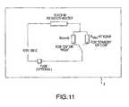
- FIG. 11is a schematic of a resistor-type heating element in accordance with one exemplary embodiment of the present invention.
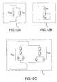
- FIGS. 12A, 12 B and 12 Care alternative embodiments of fragrance switches in accordance with the present invention.
- FIG. 13is a schematic of a PTC-type heating element in accordance with another exemplary embodiment of the present invention.
- FIG. 14is a graph showing resistance versus current for PTC-type heating elements in accordance with one exemplary embodiment of the present invention.
- the present inventionprovides a method for controlling the temperature and/or the rate of evaporation of a volatile liquid in a vaporizer device.
- a method for dispersing a volatile substancein which a vaporizing device generally comprises a heating element for heating the substance to be dispersed and means for varying the temperature of the heating element in order to control the rate of delivery of volatile substance from the vaporizer.
- a vaporizing device 1may be comprised of a heating element 2 , a support structure 3 and a volatile substance reservoir 4 in a substantially unitary configuration as depicted in FIG. 1 .
- vaporizer device 1may be comprised of support structure 3 and reservoir 4 in a unitary configuration suitably adapted to engage with heating element 2 .
- vaporizer 1may be comprised of support structure 3 and heating element 2 in a unitary configuration suitably adapted to engage with reservoir 4 as shown in FIG. 3 .
- vaporizer 1may be comprised of support heating element 2 and reservoir 4 in a unitary configuration suitably adapted to engage with support structure 3 as depicted in FIG. 4 .
- vaporizer 1may be comprised of heating element 2 , support structure 3 and reservoir 4 each suitably adapted to independently engage with the other as generally depicted in FIG. 5 .
- Heating element 2may generally be comprised of a resistor, a plurality of resistors in series or in parallel, an induction coil or any other means for electrically generating heat now known or hereafter devised by those skilled in the art. Additionally, support structure 3 may further comprise structural and/or functional features to facilitate delivery of the volatile substance from the vaporizer 1 such as a channel, semi-permeable membrane or any other means for directing or expelling a vapor now known or hereafter devised by those skilled in the art. In the exemplary embodiments described herein, such features are generally described as a wick.
- the reservoir 4may comprise a solid, liquid, gas or gel carrier in which a volatile substance may be suspended.
- Reservoir 4may further comprise an integral wick, capillary tube, at least partially exposed surface area or any other structural feature now know or hereafter devised by those skilled in the art for directing the migration of volatile substance from the reservoir 4 to an area generally proximate to heating element 2 .
- Exemplary volatile substancesmay include fragrances, disinfectants, sanitizing agents, insect repellants, insecticides, pharmaceutical preparations or any other substance having a vapor pressure suitably adapted for delivery from a vaporizer device 1 now known or hereafter devised by those skilled in the art.
- the present inventioncomprises an electric liquid vaporizer 10 that includes an electrical switch 5 that, as described in further detail herein, suitably allows the rate of evaporation of the liquid in the vaporizer to be varied.
- an exemplary embodiment of switch 5is shown in FIG. 7 .
- Switch 5generally accomplishes this by changing the amount of energy applied to a heating element of the vaporizer 10 , thereby changing the evaporation rate.
- the temperature rangeis important because above the foregoing range, vaporizer 10 tends to release more fragrance than desired, which may reduce the length of life for the product. However, in contrast, when the temperature falls below the specified range, vaporizer 10 may not meet the demand of those who desire a more densely fragranced environment.
- liquid vaporizer system 10suitably comprises a housing unit 12 and a refill bottle unit 14 .
- refill bottle unit 14is suitably configured for disposition within housing 12 and for retention therein.
- Housing unit 12suitably includes a vent system 16 and an electrical plug unit 18 .
- Bottle unit 14is configured for receipt of a vaporizable liquid material.
- the vaporizable materialcan be any number of conventional materials dispensed from vapor vaporizers including fragrances, disinfectants, sanitizing agents, insect repellants, insecticides and the like.
- the material to be volatilizedcomprises a fragrance material and system 10 is used as an air freshening device.
- refill bottle unit 14is suitably filled with a fragrance containing material and is inserted into housing unit 12 such that the fragrance material can be vaporized through operation of a heater unit which promotes or encourages vaporization from the wick.
- FIG. 8illustrates an exemplary embodiment of the positioning and placement of wick
- FIG. 10illustrates a general region 17 where the wick is to be heated. The vaporized fragrance passes through vent system 16 to the environment.
- electrical plug unit 18is plugged into a conventional electrical outlet thereby causing a heater unit to heat the liquid and vaporize the liquid that has been drawn up into the wick and allow the same to escape through the openings in vent system 16 .
- vaporizedas used herein is used in a conventional sense and is intended to include not only the formation of vapors but also the formation of small aerosol sized particles which, as is known in the art, may be generated by actuation of such device.
- Actuation of the heatermay be accomplished by operation of, for example, a three-position rocker switch 5 as depicted in FIG. 7.
- a first setting of rocker switch 5may correspond to a high-delivery fragrance setting, a second setting of rocker switch 5 to a stand-by fragrance delivery setting, and a third setting of switch 5 corresponding to the liquid vaporizer 10 being turned off.
- actuation of the heating elementmay alternatively be readily accomplished by other means, such as for example, a dial, a slide, a lever, digital control circuitry or any of various other means capable of allowing selectable functionality, now known or hereafter devised by those skilled in the art.
- the heating unitcomprises a heating element that can be readily and reliably charged through use in a conventional outlet. In such a manner, heating element (not shown) is electrically connected to plug unit 18 . Any conventional heating units may be utilized, as will be readily recognized by those skilled in the art. Similarly, and as is generally shown in the various figures, plug unit 18 may be any conventional plug unit and may be oriented in any particular direction, or even configured for rotation within housing unit 12 .
- an exemplary housing unit 12is configured to include a housing front surface 20 , a housing back surface 22 and an interconnecting top surface 24 .
- housing unit 12is configured with a partially open bottom 26 , which is configured for receipt of refill bottle unit 14 .
- Front surface 20 of housing unit 12suitably is provided with a decorative element.
- refill bottle unit 14 and housing unit 12are interconnected in a “snap-and-fit” manner and preferably the design element contained on front housing 20 is suitably configured for such purposes. That is, preferably an element on bottle unit 14 is suitably configured to cooperate with a portion of housing front wall 20 to provide the “snap-and-fit” configuration and thus, interconnect bottle unit 14 and housing unit 12 .
- various projection configurationsmay be utilized to enable bottle unit 14 to be interconnected with housing unit 12 and the configuration set forth in the drawing figures is for illustrative purposes only. Other configurations now known or hereafter devised by those skilled in the art may also be used.
- refill bottle 14may be suitably configured to be larger than housing unit 12 or alternatively smaller than housing unit 12 . Additionally, refill bottle 14 may be configured to extend beyond housing 12 or in any other shape as is now known or hereafter devised by those skilled in the art.
- bottle 14is suitably sized for use in connection with household use.
- bottle 14preferably is configured for receipt of between about 25 to about 75 milliliters of liquid material, more preferably from about 35 to about 50 milliliters of liquid.
- the weight and moment of the device/system, inclusive of the refill bottleis such that the center of gravity is appropriately positioned and the weight is less than that which would otherwise cause the device/system to be unstable within the outlet.
- refill bottle 14is a conventional bottle or similar device configured to receive a volatilizable material and hold a wick 40 firmly in place.
- wick 40will be secured to refill bottle 14 by a wick securement system 42 .
- Wick securement system 42preferably includes a wick retaining element and an attachment ring.
- wick 40is secured within wick retainer, which in turn is attached to attachment ring which is crimped or otherwise attached to neck 58 of refill bottle 14 .
- Neck 58is preferably threaded and thus includes a plurality of threads 64 .
- Threads 64are suitably configured to receive, for example, a cap for securing refill bottle 14 prior to use.
- wick 40extends substantially to the bottom 59 of refill bottle 14 .
- refill bottle 14comprises a plastic material that is compatible with the material to be vaporized.
- refill bottle 14may be formed of polypropylene (which may be clarified), barex and/or PET.
- housing 12suitably comprises a plastic material, such as polypropylene or high-density polyethylene.
- wick securement system 42may be suitably comprised of plastic, metal or other materials. It should be appreciated that the particular composition of refill bottle 14 , securement system 42 and/or housing 12 may be modified to any material composition as is now known or hereafter devised by those skilled in the art.
- Wick 40may be formed from any conventional wick material. Suitable wick materials include porous/sintered plastics such as high density polyethylene and polypropylene, bonded fibers, glass sintered fibers, ceramic materials, carbon fibers, sintered carbon, wood, compressed wood composites bundled or woven material fibers, bundled or manmade fibers. In general, wick 40 can be formed of any suitable material now known or hereafter devised by those skilled in the art.
- electrical switch 5changes the amount of heat generated by suitably providing varying resistance in the electric circuitry of the vaporizer 10 .
- the resistance valuevaries within a specified range (Rmin to Rmax).
- Rmincontrols the maximum operating temperature of the wick and thus maximum level of fragrance released from the vaporizer.
- Rminis suitably set at such a value that at an ambient temperature of 25° C.
- the maximum wick temperatureis between about 49° C. and 88° C., and preferably between 54° C. and 82° C. It should be appreciated that other temperature ranges that may be below, above and/or partially inclusive of the foregoing ranges, fall within the scope of the present invention.
- the value of Rminmay be determined by the technical parameters of the heating element used.
- an electric vaporizing vaporizer 10 containing a resistor-type heating elementcomprises a “High/Standby/Off” or “High/Low/Off” type fragrance switch 5 .
- the unitalso may include a non-polarized plug capable of 90-degree rotation. When turned to the “High” position, the unit suitably maintains a steady wick temperature of about 51° C. (measured at the top tip of the wick).
- the wick temperatureWhen turned to the “Standby” position, the wick temperature is decreased to about 24° C., or otherwise slightly higher than the ambient room temperature of about 23° C.
- the vaporizermay be readily redesigned to adjust the fragrance output at the “High” position by varying the resistance of the heating element or the Rmin.
- the fragrance output at the “Standby” or “Low” positioncan also be readily adjusted by altering the Rmax.
- Rmaxsuitably controls the minimum wick temperature and minimum level of fragrance release from the vaporizer.
- Rmaxis set at a value such that the minimum wick temperature is greater than the ambient temperature but less than the maximum wick temperature.
- the minimum wick temperaturecan be set to substantially deliver a continuous weaker but significantly fragranced environment.
- the fragrance switchcan be typified as “High/Low” for fragrance control.
- the Rmaxcan be adapted such that fragrance delivery is slow enough that consumers will hardly notice it.
- the fragrance switch 5can be typified as “On/Standby.”
- the effective resistance of an exemplary fragrance switch 5may include a single resistor, a variable resistor, sets of multiple resistors in parallel or series arrangements as well as other resistive means well known in the art.
- the resistor Rmax and/or Rmin connected to the fragrance switch 5can be a single resistor (as depicted in FIG. 12 A), a variable resistor (as depicted in FIG. 12 B), or a set of multiple resistors in parallel or series arrangement (as depicted in FIG. 12 C).
- the effective resistance valuesare suitably selected to meet the criteria described for Rmax and Rmin to deliver satisfactory product performance and fragrance delivery control.
- a fragrance switch 5in accordance with an exemplary embodiment of the present invention, to continuously permit an electrical current passing through the heating element of the fragrance vaporizer, regardless of where the switch 5 is placed.
- the assembly processis simplified as well as making the device suitably adaptable to most outlets.
- the heating elementmay be suitably configured to prevent overheating caused by electrical surges.
- a positive temperature coefficient (PTC) thermistorhas such properties. That is, a PTC suitably adapted to adjust its resistance to compensate for variations of electrical voltage or current in a specified range. Within this range, the energy output of the vaporizer and the wick temperature can generally be maintained with respect to the corresponding voltage/current flux.
- PTCpositive temperature coefficient
- PTC elementsare known for a number of applications.
- Table 1illustrates numerous of such applications:
- PTC elementsare heretofore unknown when used in connection with air fresheners and corrected in series with variable resistances in a manner such as described below, thud providing numerous benefits over the prior art.
- FIG. 13depicts a plug-in liquid electric air freshener with the housing configuration shown in FIG. 7 further including a PTC-type heating element.
- Exemplary technical parameters of the PTCare shown in Table 2 below.
- the input voltageis varied from 110V to 140V.
- the resistance of the PTCincreases to maintain the wattage at substantially the same level.
- the wick temperature and the fragrance evaporationremain approximately the same although the voltage is increased.
- resistance valuesare varied from 0 (R min always at zero) to R max .
- the PTC type of heating elementgenerally provides a maximum wick temperature for the evaporative release of fragrance.
- R maxa resistor having large resistance value is incorporated into the circuit. As described below, the resistance value is suitably large enough to reduce the electrical current and thus the PTC temperature to a low level that is beyond the range for PTC compensation.
- a “HIGH/LOW” or “HIGH/STANDBY” type switch for fragrance controlmay be incorporated as shown in FIG. 13 .
- switch 5As switch 5 is set to a position where the effective resistance is zero, the vaporizer heats the wick to the maximum operating temperature between 60°-66° C., and significant fragrance delivery may be observed.
- R maxAs switch 5 is set to R max , a large resistor is incorporated such that the current rating is significantly reduced to a level beyond the PTC's capability for compensation thus lowering the temperature.
- the correlation among the R max , body temperature of R max , current rating, and wick temperatureis shown.
- the resultsshow that when the R max is generally small (e.g., ⁇ 1 Kohms), the tendency of current reduction is compensated by the PTC.
- the R max in Table 4is preferred to be greater than 31.7 Kohm so that the actual energy consumption is within the limit of the energy rating of R max .
- R maxis suitably selected to have a large resistance value relative to R max .
- R maxis suitably connected to PTC in serial to reduce the electrical current through the PTC to such a low level that is out of PTC's compensation range (as illustrated in FIG. 14 ).
- the PTC elementhas a compensation range of less than about 21 Kohms.
- the present inventionprovides means for controlling the temperature of the heating element of a vaporizer device.
- various principles and applications of the present inventionhave been described by way of the preceding exemplary embodiments; other combinations and/or modifications of the above-described structures, arrangements, applications, proportions, elements, materials or components used in the practice of the present invention, in addition to those not specifically recited, may be varied or otherwise particularly adapted by those skilled in the art to specific environments, manufacturing or design parameters or other operating requirements without departing from the general principles of the same.
- various changes in the Configuration of the housing unit, plug unit and/or heating unitmay be made without departing from the scope of the present invention.
- wick temperature control mechanismsmay be augmented or modified in accordance with the various teachings herein as well as other configurations known in the art and not described herein. Accordingly, these and other changes or modifications are intended to be included within the scope of the present invention as set forth in the appended claims.
Landscapes
- Life Sciences & Earth Sciences (AREA)
- Engineering & Computer Science (AREA)
- Health & Medical Sciences (AREA)
- Pest Control & Pesticides (AREA)
- General Health & Medical Sciences (AREA)
- Mechanical Engineering (AREA)
- Combustion & Propulsion (AREA)
- Chemical & Material Sciences (AREA)
- General Engineering & Computer Science (AREA)
- Epidemiology (AREA)
- Public Health (AREA)
- Animal Behavior & Ethology (AREA)
- Veterinary Medicine (AREA)
- Toxicology (AREA)
- Insects & Arthropods (AREA)
- Wood Science & Technology (AREA)
- Zoology (AREA)
- Environmental Sciences (AREA)
- Catching Or Destruction (AREA)
Abstract
Description
| TABLE 1 | ||||
| Surface | ||||
| Products of | Temper- | Max. | ||
| TianCheng | Resistance at | ature/ | Voltage/ | |
| Thermistor Co. | 25° C./Ω | ° C. | V | Main Purposes |
| MZ9-50C270V1 | 500˜1500 | 50 | 270 | Agricultural |
| Heater | ||||
| MZ9-75C50V1 | 8˜20 | 75 | 50 | Physical |
| Therapy | ||||
| Machine | ||||
| MZ9-75C270V1 | 500˜1500 | 75 | 270 | Physical |
| Therapy | ||||
| Machine | ||||
| MZ9-85C140V1 | 300˜800 | 85 | 140 | Massaging |
| Machine | ||||
| MZ9-90C140V1 | 150˜400 | 90 | 140 | Massaging |
| Machine | ||||
| MZ9-100C270V1 | 600˜1500 | 100 | 270 | Massaging |
| Machine | ||||
| MZ9-110C50V1 | 10˜25 | 110 | 50 | Motor Car |
| MZ9-110C270V1 | 500˜1500 | 110 | 270 | Shoe Dryer |
| MZ9-130C270V1 | 500˜1500 | 130 | 270 | Mosquito |
| Destroyer | ||||
| MZ9-130C270V2 | 500˜1500 | 130 | 270 | Heating Plate |
| MZ9-150C140V1 | 200˜800 | 150 | 140 | Heater for |
| Degausser | ||||
| MZ9-150C50V1 | 20˜50 | 150 | 30 | Heating Plate |
| MZ9-155C50V1 | 50˜90 | 155 | 50 | Delay switch |
| MZ9-155C270V1 | 200˜800 | 155 | 270 | Heater for |
| Degausser | ||||
| MZ9-155C270V2 | 500˜1500 | 155 | 270 | Heating Plate |
| MZ9-160C50V1 | 8˜20 | 160 | 50 | Automobile |
| MZ9-160C270V1 | 500˜1500 | 160 | 270 | Humidifier |
| MZ9-175C140V1 | 150˜500 | 175 | 140 | Heating Plate |
| MZ9-180C50V1 | 1˜5 | 180 | 50 | Automobile |
| MZ9-180C270V1 | 500˜1500 | 180 | 270 | Heating Plate |
| MZ9-185C270V1 | 200˜800 | 185 | 270 | Heater for |
| Degausser | ||||
| MZ9-230C270V1 | 800˜2K | 230 | 270 | Hair Roller |
| MZ9-230C270V2 | 800˜2K | 230 | 270 | Mosquito |
| Destroyer | ||||
| MZ9-250C270V1 | 800˜2K | 250 | 270 | Mosquito |
| Destroyer | ||||
| MZ9-250C270V3 | 2˜5K | 250 | 270 | Water Heater |
| MZ9-250C140V1 | 300˜1K | 250 | 140 | Heating Plate |
| MZ9-255C270V1 | 800˜2K | 255 | 270 | Heating Plate |
| MZ9-255C270V1 | 0.5˜3K | 255 | 270 | Hot Glue Gun |
| MZ9-280C50V1 | 8˜20 | 280 | 50 | Air Heater |
| MZ9-280C140V1 | 300˜800 | 280 | 140 | Air Heater |
| MZ9-280C270V1 | 0.8˜3.5K | 280 | 270 | Air Heater |
| MZ9-290C270V1 | 0.5˜3K | 290 | 270 | Hot Glue Gun |
| TABLE 2 |
| Technical parameters of the PTC |
| Technical Parameters |
| Heater lid (top) | Nylon 66 + Glass Fiber, wt = 4 g |
| Heater enclosure (bottom) | Nylon 66 + Glass Fiber, wt = 4 g |
| Shape | toroidal |
| Color | Black |
| Dimensions | Outer diameter 30 mm |
| Inner diameter: 10 mm | |
| Assembled height: 16 mm | |
| PTC stone | A semiconductor on a ceramic base. |
| Material | Ceramic resistor |
| Thermal Characteristics | Reference temperature: 110° C. |
| Surface temperature at Vmax = 135° C. ± | |
| 7° C. | |
| Dimensions | Diameter: 8 mm +/− 0.5 mm |
| Thickness: 3 mm +/− 0.1 mm | |
| TABLE 3 |
| Current rating, wattage, and wick temperature with different input voltages |
| Input | Current | Wattage | Wick Temperature | ||
| Voltage (Vac) | rating (mA) | (W) | (° C.) | ||
| 110 | 15.8 | 1.7 | 78 | ||
| 120 | 14.5 | 1.7 | 80 | ||
| 130 | 13.5 | 1.7 | 81 | ||
| 140 | 12.7 | 1.8 | 82 | ||
Claims (6)
Priority Applications (1)
| Application Number | Priority Date | Filing Date | Title |
|---|---|---|---|
| US10/462,558US6792199B2 (en) | 2000-02-25 | 2003-06-16 | Variable temperature vaporizer |
Applications Claiming Priority (3)
| Application Number | Priority Date | Filing Date | Title |
|---|---|---|---|
| US18481700P | 2000-02-25 | 2000-02-25 | |
| US09/792,507US6661967B2 (en) | 2000-02-25 | 2001-02-23 | Variable temperature vaporizer |
| US10/462,558US6792199B2 (en) | 2000-02-25 | 2003-06-16 | Variable temperature vaporizer |
Related Parent Applications (1)
| Application Number | Title | Priority Date | Filing Date |
|---|---|---|---|
| US09/792,507Continuation-In-PartUS6661967B2 (en) | 2000-02-25 | 2001-02-23 | Variable temperature vaporizer |
Publications (2)
| Publication Number | Publication Date |
|---|---|
| US20040071456A1 US20040071456A1 (en) | 2004-04-15 |
| US6792199B2true US6792199B2 (en) | 2004-09-14 |
Family
ID=26880495
Family Applications (1)
| Application Number | Title | Priority Date | Filing Date |
|---|---|---|---|
| US10/462,558Expired - LifetimeUS6792199B2 (en) | 2000-02-25 | 2003-06-16 | Variable temperature vaporizer |
Country Status (1)
| Country | Link |
|---|---|
| US (1) | US6792199B2 (en) |
Cited By (39)
| Publication number | Priority date | Publication date | Assignee | Title |
|---|---|---|---|---|
| USD541922S1 (en) | 2005-03-31 | 2007-05-01 | S.C. Johnson & Son, Inc. | Diffuser |
| USD542400S1 (en) | 2005-03-31 | 2007-05-08 | S.C. Johnson & Son, Inc. | Diffuser |
| US7281811B2 (en) | 2005-03-31 | 2007-10-16 | S. C. Johnson & Son, Inc. | Multi-clarity lenses |
| US7350720B2 (en) | 2004-02-03 | 2008-04-01 | S.C. Johnson & Son, Inc. | Active material emitting device |
| US20080130266A1 (en)* | 2006-12-05 | 2008-06-05 | Innovative Instruments, Inc. | Fragrancer |
| US20080129226A1 (en)* | 2006-12-05 | 2008-06-05 | Innovative Instruments, Inc. | Simulated Open Flame Illumination |
| US7389943B2 (en) | 2004-06-30 | 2008-06-24 | S.C. Johnson & Son, Inc. | Electromechanical apparatus for dispensing volatile substances with single dispensing mechanism and cartridge for holding multiple receptacles |
| US20080226269A1 (en)* | 2007-03-16 | 2008-09-18 | Innovative Instruments, Inc. | Vapor generator |
| US7469844B2 (en) | 2002-11-08 | 2008-12-30 | S.C. Johnson & Son, Inc. | Diffusion device and method of diffusing |
| USD584809S1 (en) | 2008-02-04 | 2009-01-13 | S. C. Johnson & Son, Inc. | Dispensing device |
| US7503668B2 (en) | 2004-02-03 | 2009-03-17 | S.C. Johnson & Son, Inc. | Device providing coordinated emission of light and volatile active |
| US20090148142A1 (en)* | 2007-12-04 | 2009-06-11 | Givaudan Sa | Usb-powered air freshener |
| US7589340B2 (en) | 2005-03-31 | 2009-09-15 | S.C. Johnson & Son, Inc. | System for detecting a container or contents of the container |
| US7610118B2 (en) | 2002-11-08 | 2009-10-27 | S.C. Johnson & Son, Inc. | Dispensing of multiple volatile substances |
| US7622073B2 (en) | 2005-04-12 | 2009-11-24 | S.C. Johnson & Son, Inc. | Apparatus for and method of dispensing active materials |
| US7643734B2 (en) | 2005-03-31 | 2010-01-05 | S.C. Johnson & Son, Inc. | Bottle eject mechanism |
| US20100059601A1 (en)* | 2008-09-05 | 2010-03-11 | The Dial Corporation | Energy conserving vapor-dispersing device with optional repeating off cycles |
| US7687744B2 (en) | 2002-05-13 | 2010-03-30 | S.C. Johnson & Son, Inc. | Coordinated emission of fragrance, light, and sound |
| US20100078498A1 (en)* | 2008-09-29 | 2010-04-01 | Gasper Thomas P | Method of Dispensing a Volatile Material |
| US20100078497A1 (en)* | 2008-09-29 | 2010-04-01 | Gasper Thomas P | Method of Dispensing a Volatile Material |
| USD618550S1 (en) | 2009-11-12 | 2010-06-29 | Brandywine Product Group International Inc. | Bottle |
| US7824627B2 (en) | 2004-02-03 | 2010-11-02 | S.C. Johnson & Son, Inc. | Active material and light emitting device |
| US20110068190A1 (en)* | 2009-09-21 | 2011-03-24 | Gasper Thomas P | Methods of Emitting a Volatile Material from a Diffuser |
| US7932482B2 (en) | 2003-02-07 | 2011-04-26 | S.C. Johnson & Son, Inc. | Diffuser with light emitting diode nightlight |
| USD639923S1 (en) | 2010-04-15 | 2011-06-14 | S.C. Johnson & Son, Inc. | Dispensing device |
| US8186075B2 (en)* | 2006-05-31 | 2012-05-29 | Joel Beckett | Forced air flow electric shoe dryer |
| US8320751B2 (en) | 2007-12-20 | 2012-11-27 | S.C. Johnson & Son, Inc. | Volatile material diffuser and method of preventing undesirable mixing of volatile materials |
| US8442390B2 (en) | 2007-08-29 | 2013-05-14 | Philip Morris Usa Inc. | Pulsed aerosol generation |
| US20130125531A1 (en)* | 2009-12-24 | 2013-05-23 | Inergy Automotive Systems Research (Societe Anonyme) | Reservoir and tank equipped with a self-regulating heating element |
| US8632059B2 (en) | 2001-10-04 | 2014-01-21 | Ctr Consultoria Tecnica E Representacoes, Lda | Dispersing fragrances |
| US20160150828A1 (en)* | 2014-12-02 | 2016-06-02 | Gabriel Marc Goldstein | Vaporizing reservoir |
| US9526808B2 (en) | 2009-10-13 | 2016-12-27 | Philip Morris Usa Inc. | Air freshening device |
| US20170258137A1 (en)* | 2016-03-11 | 2017-09-14 | Barry S. Smith | E-vaping device cartridge with internal conductive element |
| US20180027878A1 (en)* | 2016-07-31 | 2018-02-01 | Charles Dendy | Electronic vaping device, battery section, and charger |
| EP3282813A1 (en) | 2016-08-09 | 2018-02-14 | Henkel AG & Co. KGaA | Device for emanating materials |
| US10258710B1 (en) | 2017-09-22 | 2019-04-16 | S. C. Johnson & Son, Inc. | Container for holding volatile materials |
| US20190216967A1 (en)* | 2018-01-18 | 2019-07-18 | The Procter & Gamble Company | Method of delivering a volatile composition into the air |
| US11484022B2 (en) | 2019-10-15 | 2022-11-01 | S. C. Johnson & Son, Inc. | Insect trap device |
| US12290060B2 (en) | 2019-10-15 | 2025-05-06 | S. C. Johnson & Son, Inc. | Insect trap device |
Families Citing this family (13)
| Publication number | Priority date | Publication date | Assignee | Title |
|---|---|---|---|---|
| JP2008538310A (en)* | 2005-04-12 | 2008-10-23 | エス.シー. ジョンソン アンド サン、インコーポレイテッド | Diffusion apparatus and diffusion method |
| US7416766B2 (en)* | 2005-08-16 | 2008-08-26 | S.C. Johnson & Son, Inc. | Bottles made from metallocene polypropylene for delivery of fragrances |
| CN201067079Y (en) | 2006-05-16 | 2008-06-04 | 韩力 | Simulated aerosol inhaler |
| EP2037734A1 (en)* | 2006-05-19 | 2009-03-25 | Porex Corporation | Vapor dispenser with indicator |
| US7677536B2 (en) | 2006-06-12 | 2010-03-16 | Kaz, Incorporated | Humidifier with controlled heated scent mechanism |
| WO2010014996A2 (en)* | 2008-08-01 | 2010-02-04 | Porex Corporation | Wicks for dispensers of vaporizable materials |
| WO2010081013A1 (en)* | 2009-01-09 | 2010-07-15 | Porex Corporation | Hydrophilic porous wicks for vaporizable materials |
| US8983279B2 (en)* | 2012-07-31 | 2015-03-17 | S.C. Johnson & Son, Inc. | Volatile material dispenser and method of emitting a volatile material |
| GB2504731B (en)* | 2012-08-08 | 2015-03-25 | Reckitt & Colman Overseas | Device for evaporating a volatile fluid |
| GB2504733B (en)* | 2012-08-08 | 2015-05-20 | Reckitt & Colman Overseas | Device for evaporating a volatile material |
| CA2985988C (en)* | 2014-05-12 | 2021-05-25 | Loto Labs, Inc. | Improved vaporizer device |
| WO2019228925A1 (en)* | 2018-06-01 | 2019-12-05 | Tdk Electronics Ag | Heating module |
| USD1023265S1 (en)* | 2020-11-02 | 2024-04-16 | Reckitt & Colman (Overseas) Hygiene Home Limited | Electrically powered air treatment device |
Citations (48)
| Publication number | Priority date | Publication date | Assignee | Title |
|---|---|---|---|---|
| US1944821A (en) | 1934-01-23 | Perfume diffuses | ||
| US1994932A (en) | 1932-02-27 | 1935-03-19 | Vidal Pierre Lucien | System for vaporizing liquids and the absorption of smoke, evil odors, and the like |
| US2597195A (en) | 1950-03-18 | 1952-05-20 | Garland D Runnels | Vaporizer |
| US2611068A (en) | 1946-04-12 | 1952-09-16 | William H Wellens | Pivotally mounted plug and vaporizer |
| US3375774A (en) | 1967-01-05 | 1968-04-02 | Matsushita Electric Industrial Co Ltd | Fully automatic electric coffee pot |
| US3400252A (en) | 1965-10-20 | 1968-09-03 | Matsushita Electric Industrial Co Ltd | Electrical heating device |
| US3476293A (en) | 1967-08-29 | 1969-11-04 | Texas Instruments Inc | Aerosol heater with improved control means |
| US3527924A (en) | 1968-05-03 | 1970-09-08 | Monsanto Co | Apparatus for identifying fibers |
| US3564205A (en) | 1969-11-20 | 1971-02-16 | Robertshaw Controls Co | Temperature control circuits |
| US3584196A (en) | 1968-11-29 | 1971-06-08 | Matsushita Electric Industrial Co Ltd | Automatic electric cooking appliance |
| US3651308A (en) | 1969-06-27 | 1972-03-21 | Matsushita Electric Industrial Co Ltd | Automatic electric cooker |
| US3872280A (en) | 1972-05-02 | 1975-03-18 | Intergadgets Ag | Device for vaporizing substances |
| US3943331A (en) | 1974-12-06 | 1976-03-09 | Multi-State Devices, Ltd. | Temperature control circuit |
| US4316080A (en) | 1980-02-29 | 1982-02-16 | Theodore Wroblewski | Temperature control devices |
| US4467177A (en) | 1982-03-26 | 1984-08-21 | Zobele Industrie Chimiche S.P.A. | Heating device for tablets containing evaporable substances at different temperatures |
| US4663315A (en) | 1984-01-31 | 1987-05-05 | Earth Chemical Company, Limited | Device and method for vaporizing thermally vaporizable composition |
| US4724976A (en) | 1987-01-12 | 1988-02-16 | Lee Alfredo A | Collapsible container |
| US4731520A (en) | 1986-06-24 | 1988-03-15 | Charles Of The Ritz Group Ltd. | Aroma diffuser apparatus |
| US4739928A (en) | 1985-10-15 | 1988-04-26 | The Drackett Company | Air freshener dispenser |
| US4745705A (en) | 1986-07-18 | 1988-05-24 | Sumitomo Chemical Company, Limited | Method for killing insects by heating fumigation |
| US4874924A (en) | 1987-04-21 | 1989-10-17 | Tdk Corporation | PTC heating device |
| USD307180S (en) | 1987-10-30 | 1990-04-10 | Creative Environments Inc. | Electric fragrance dispenser |
| US5016772A (en) | 1990-03-02 | 1991-05-21 | Wilk Peter J | Collapsible receptacle assembly and related method |
| US5038394A (en) | 1988-02-10 | 1991-08-06 | Earth Chemical Co., Ltd. | Thermal vaporizer |
| US5050762A (en) | 1990-03-30 | 1991-09-24 | Dusaline Giorgi | Trash container |
| WO1991015249A1 (en) | 1990-04-11 | 1991-10-17 | Globol Gmbh | Electric evaporator for active substances |
| US5095647A (en) | 1989-09-29 | 1992-03-17 | Zobele Industrie Chimiche S.P.A. | Apparatus to keep flying insects, particularly mosquitoes, away from people |
| US5111477A (en) | 1990-05-07 | 1992-05-05 | Technical Concepts, L.P. | Fragrance diffuser |
| US5161646A (en) | 1991-03-22 | 1992-11-10 | Wellington Leisure Products | Animal attractant scent dispensing device |
| USD335530S (en) | 1991-01-08 | 1993-05-11 | Globol Gmbh | Electrical evaporator |
| US5222186A (en) | 1991-12-06 | 1993-06-22 | Globol Gmbh | Electrical apparatus for vaporizing of active substances |
| US5290546A (en) | 1988-02-10 | 1994-03-01 | Earth Chemical Co., Ltd. | Method for thermal vaporization of chemical |
| USD346207S (en) | 1992-10-14 | 1994-04-19 | S. C. Johnson & Son, Inc. | Decorative cover for use on a volatile dispenser unit or heater unit |
| USD357330S (en) | 1993-04-14 | 1995-04-11 | Rockitt & Colman Inc. | Electric air freshener with nightlight |
| US5484086A (en) | 1993-04-20 | 1996-01-16 | Pu; Kuan H. | Perfume gas generating device |
| US5591395A (en) | 1995-08-03 | 1997-01-07 | S. C. Johnson & Son, Inc. | Method of disinfecting air |
| US5647053A (en) | 1995-10-11 | 1997-07-08 | S. C. Johnson & Son, Inc. | Vapor dipensing device |
| USD381443S (en) | 1996-11-07 | 1997-07-22 | John Manufacturing Limited | Combined night light and insect repeller |
| USD386974S (en) | 1996-10-17 | 1997-12-02 | S. C. Johnson & Son, Inc. | Combined bottle and cap |
| USD393063S (en) | 1996-10-17 | 1998-03-31 | S. C. Johnson & Son, Inc. | Volatile liquid dispenser |
| WO1998019526A1 (en) | 1996-11-07 | 1998-05-14 | Zobele Industrie Chimiche S.P.A. | Adjustable-intensity heating device for the evaporation of chemical substances |
| US5773795A (en) | 1994-08-12 | 1998-06-30 | David & Baader--DBK Spezialfabrik Elektrischer Apparate u. Heizwiderstande GmbH | Electrically heatable warming device |
| USD407476S (en) | 1997-03-04 | 1999-03-30 | Bath & Body Works, Inc. | Air freshener |
| US5909845A (en) | 1996-06-28 | 1999-06-08 | S. C. Johnson & Son, Inc. | Wick-based liquid emanation system with child-resistant overcap |
| US5926614A (en) | 1994-08-03 | 1999-07-20 | Steinel Gmbh & Co. Kg | Electric device for the vaporization of additives |
| US5940577A (en) | 1994-08-03 | 1999-08-17 | Steinel Gmbh & Co. Kg | Electric device for the vaporization of additives |
| US6104867A (en) | 1999-06-16 | 2000-08-15 | The Dial Corporation | Method and apparatus for liquid vaporization |
| US6661967B2 (en)* | 2000-02-25 | 2003-12-09 | The Dial Corporation | Variable temperature vaporizer |
- 2003
- 2003-06-16USUS10/462,558patent/US6792199B2/ennot_activeExpired - Lifetime
Patent Citations (48)
| Publication number | Priority date | Publication date | Assignee | Title |
|---|---|---|---|---|
| US1944821A (en) | 1934-01-23 | Perfume diffuses | ||
| US1994932A (en) | 1932-02-27 | 1935-03-19 | Vidal Pierre Lucien | System for vaporizing liquids and the absorption of smoke, evil odors, and the like |
| US2611068A (en) | 1946-04-12 | 1952-09-16 | William H Wellens | Pivotally mounted plug and vaporizer |
| US2597195A (en) | 1950-03-18 | 1952-05-20 | Garland D Runnels | Vaporizer |
| US3400252A (en) | 1965-10-20 | 1968-09-03 | Matsushita Electric Industrial Co Ltd | Electrical heating device |
| US3375774A (en) | 1967-01-05 | 1968-04-02 | Matsushita Electric Industrial Co Ltd | Fully automatic electric coffee pot |
| US3476293A (en) | 1967-08-29 | 1969-11-04 | Texas Instruments Inc | Aerosol heater with improved control means |
| US3527924A (en) | 1968-05-03 | 1970-09-08 | Monsanto Co | Apparatus for identifying fibers |
| US3584196A (en) | 1968-11-29 | 1971-06-08 | Matsushita Electric Industrial Co Ltd | Automatic electric cooking appliance |
| US3651308A (en) | 1969-06-27 | 1972-03-21 | Matsushita Electric Industrial Co Ltd | Automatic electric cooker |
| US3564205A (en) | 1969-11-20 | 1971-02-16 | Robertshaw Controls Co | Temperature control circuits |
| US3872280A (en) | 1972-05-02 | 1975-03-18 | Intergadgets Ag | Device for vaporizing substances |
| US3943331A (en) | 1974-12-06 | 1976-03-09 | Multi-State Devices, Ltd. | Temperature control circuit |
| US4316080A (en) | 1980-02-29 | 1982-02-16 | Theodore Wroblewski | Temperature control devices |
| US4467177A (en) | 1982-03-26 | 1984-08-21 | Zobele Industrie Chimiche S.P.A. | Heating device for tablets containing evaporable substances at different temperatures |
| US4663315A (en) | 1984-01-31 | 1987-05-05 | Earth Chemical Company, Limited | Device and method for vaporizing thermally vaporizable composition |
| US4739928A (en) | 1985-10-15 | 1988-04-26 | The Drackett Company | Air freshener dispenser |
| US4731520A (en) | 1986-06-24 | 1988-03-15 | Charles Of The Ritz Group Ltd. | Aroma diffuser apparatus |
| US4745705A (en) | 1986-07-18 | 1988-05-24 | Sumitomo Chemical Company, Limited | Method for killing insects by heating fumigation |
| US4724976A (en) | 1987-01-12 | 1988-02-16 | Lee Alfredo A | Collapsible container |
| US4874924A (en) | 1987-04-21 | 1989-10-17 | Tdk Corporation | PTC heating device |
| USD307180S (en) | 1987-10-30 | 1990-04-10 | Creative Environments Inc. | Electric fragrance dispenser |
| US5038394A (en) | 1988-02-10 | 1991-08-06 | Earth Chemical Co., Ltd. | Thermal vaporizer |
| US5290546A (en) | 1988-02-10 | 1994-03-01 | Earth Chemical Co., Ltd. | Method for thermal vaporization of chemical |
| US5095647A (en) | 1989-09-29 | 1992-03-17 | Zobele Industrie Chimiche S.P.A. | Apparatus to keep flying insects, particularly mosquitoes, away from people |
| US5016772A (en) | 1990-03-02 | 1991-05-21 | Wilk Peter J | Collapsible receptacle assembly and related method |
| US5050762A (en) | 1990-03-30 | 1991-09-24 | Dusaline Giorgi | Trash container |
| WO1991015249A1 (en) | 1990-04-11 | 1991-10-17 | Globol Gmbh | Electric evaporator for active substances |
| US5111477A (en) | 1990-05-07 | 1992-05-05 | Technical Concepts, L.P. | Fragrance diffuser |
| USD335530S (en) | 1991-01-08 | 1993-05-11 | Globol Gmbh | Electrical evaporator |
| US5161646A (en) | 1991-03-22 | 1992-11-10 | Wellington Leisure Products | Animal attractant scent dispensing device |
| US5222186A (en) | 1991-12-06 | 1993-06-22 | Globol Gmbh | Electrical apparatus for vaporizing of active substances |
| USD346207S (en) | 1992-10-14 | 1994-04-19 | S. C. Johnson & Son, Inc. | Decorative cover for use on a volatile dispenser unit or heater unit |
| USD357330S (en) | 1993-04-14 | 1995-04-11 | Rockitt & Colman Inc. | Electric air freshener with nightlight |
| US5484086A (en) | 1993-04-20 | 1996-01-16 | Pu; Kuan H. | Perfume gas generating device |
| US5940577A (en) | 1994-08-03 | 1999-08-17 | Steinel Gmbh & Co. Kg | Electric device for the vaporization of additives |
| US5926614A (en) | 1994-08-03 | 1999-07-20 | Steinel Gmbh & Co. Kg | Electric device for the vaporization of additives |
| US5773795A (en) | 1994-08-12 | 1998-06-30 | David & Baader--DBK Spezialfabrik Elektrischer Apparate u. Heizwiderstande GmbH | Electrically heatable warming device |
| US5591395A (en) | 1995-08-03 | 1997-01-07 | S. C. Johnson & Son, Inc. | Method of disinfecting air |
| US5647053A (en) | 1995-10-11 | 1997-07-08 | S. C. Johnson & Son, Inc. | Vapor dipensing device |
| US5909845A (en) | 1996-06-28 | 1999-06-08 | S. C. Johnson & Son, Inc. | Wick-based liquid emanation system with child-resistant overcap |
| USD393063S (en) | 1996-10-17 | 1998-03-31 | S. C. Johnson & Son, Inc. | Volatile liquid dispenser |
| USD386974S (en) | 1996-10-17 | 1997-12-02 | S. C. Johnson & Son, Inc. | Combined bottle and cap |
| USD381443S (en) | 1996-11-07 | 1997-07-22 | John Manufacturing Limited | Combined night light and insect repeller |
| WO1998019526A1 (en) | 1996-11-07 | 1998-05-14 | Zobele Industrie Chimiche S.P.A. | Adjustable-intensity heating device for the evaporation of chemical substances |
| USD407476S (en) | 1997-03-04 | 1999-03-30 | Bath & Body Works, Inc. | Air freshener |
| US6104867A (en) | 1999-06-16 | 2000-08-15 | The Dial Corporation | Method and apparatus for liquid vaporization |
| US6661967B2 (en)* | 2000-02-25 | 2003-12-09 | The Dial Corporation | Variable temperature vaporizer |
Cited By (59)
| Publication number | Priority date | Publication date | Assignee | Title |
|---|---|---|---|---|
| US8632059B2 (en) | 2001-10-04 | 2014-01-21 | Ctr Consultoria Tecnica E Representacoes, Lda | Dispersing fragrances |
| US7687744B2 (en) | 2002-05-13 | 2010-03-30 | S.C. Johnson & Son, Inc. | Coordinated emission of fragrance, light, and sound |
| US7610118B2 (en) | 2002-11-08 | 2009-10-27 | S.C. Johnson & Son, Inc. | Dispensing of multiple volatile substances |
| US7469844B2 (en) | 2002-11-08 | 2008-12-30 | S.C. Johnson & Son, Inc. | Diffusion device and method of diffusing |
| US7932482B2 (en) | 2003-02-07 | 2011-04-26 | S.C. Johnson & Son, Inc. | Diffuser with light emitting diode nightlight |
| US7350720B2 (en) | 2004-02-03 | 2008-04-01 | S.C. Johnson & Son, Inc. | Active material emitting device |
| US7824627B2 (en) | 2004-02-03 | 2010-11-02 | S.C. Johnson & Son, Inc. | Active material and light emitting device |
| US7503668B2 (en) | 2004-02-03 | 2009-03-17 | S.C. Johnson & Son, Inc. | Device providing coordinated emission of light and volatile active |
| US7389943B2 (en) | 2004-06-30 | 2008-06-24 | S.C. Johnson & Son, Inc. | Electromechanical apparatus for dispensing volatile substances with single dispensing mechanism and cartridge for holding multiple receptacles |
| USD541922S1 (en) | 2005-03-31 | 2007-05-01 | S.C. Johnson & Son, Inc. | Diffuser |
| US7281811B2 (en) | 2005-03-31 | 2007-10-16 | S. C. Johnson & Son, Inc. | Multi-clarity lenses |
| USD546931S1 (en) | 2005-03-31 | 2007-07-17 | S.C. Johnson & Son, Inc. | Diffuser |
| US7589340B2 (en) | 2005-03-31 | 2009-09-15 | S.C. Johnson & Son, Inc. | System for detecting a container or contents of the container |
| USD542400S1 (en) | 2005-03-31 | 2007-05-08 | S.C. Johnson & Son, Inc. | Diffuser |
| US7643734B2 (en) | 2005-03-31 | 2010-01-05 | S.C. Johnson & Son, Inc. | Bottle eject mechanism |
| US7622073B2 (en) | 2005-04-12 | 2009-11-24 | S.C. Johnson & Son, Inc. | Apparatus for and method of dispensing active materials |
| US8186075B2 (en)* | 2006-05-31 | 2012-05-29 | Joel Beckett | Forced air flow electric shoe dryer |
| US20080129226A1 (en)* | 2006-12-05 | 2008-06-05 | Innovative Instruments, Inc. | Simulated Open Flame Illumination |
| US20080130266A1 (en)* | 2006-12-05 | 2008-06-05 | Innovative Instruments, Inc. | Fragrancer |
| US20080226269A1 (en)* | 2007-03-16 | 2008-09-18 | Innovative Instruments, Inc. | Vapor generator |
| US8897630B2 (en) | 2007-08-29 | 2014-11-25 | Philip Morris Usa Inc. | Pulsed aerosol generation |
| US8442390B2 (en) | 2007-08-29 | 2013-05-14 | Philip Morris Usa Inc. | Pulsed aerosol generation |
| US20090148142A1 (en)* | 2007-12-04 | 2009-06-11 | Givaudan Sa | Usb-powered air freshener |
| US8320751B2 (en) | 2007-12-20 | 2012-11-27 | S.C. Johnson & Son, Inc. | Volatile material diffuser and method of preventing undesirable mixing of volatile materials |
| USD584809S1 (en) | 2008-02-04 | 2009-01-13 | S. C. Johnson & Son, Inc. | Dispensing device |
| US20100059601A1 (en)* | 2008-09-05 | 2010-03-11 | The Dial Corporation | Energy conserving vapor-dispersing device with optional repeating off cycles |
| US8197762B2 (en) | 2008-09-29 | 2012-06-12 | S.C. Johnson & Son, Inc. | Method of dispensing a volatile material |
| US8293172B2 (en) | 2008-09-29 | 2012-10-23 | S.C. Johnson & Son, Inc. | Method of dispensing a volatile material |
| US20100078497A1 (en)* | 2008-09-29 | 2010-04-01 | Gasper Thomas P | Method of Dispensing a Volatile Material |
| US20100078498A1 (en)* | 2008-09-29 | 2010-04-01 | Gasper Thomas P | Method of Dispensing a Volatile Material |
| US20110068190A1 (en)* | 2009-09-21 | 2011-03-24 | Gasper Thomas P | Methods of Emitting a Volatile Material from a Diffuser |
| US9669125B2 (en) | 2009-09-21 | 2017-06-06 | S. C. Johnson & Son, Inc. | Methods of emitting a volatile material from a diffuser |
| US9526808B2 (en) | 2009-10-13 | 2016-12-27 | Philip Morris Usa Inc. | Air freshening device |
| USD626845S1 (en) | 2009-11-12 | 2010-11-09 | Brandywine Product Group International Inc. | Bottle |
| USD618550S1 (en) | 2009-11-12 | 2010-06-29 | Brandywine Product Group International Inc. | Bottle |
| US20130125531A1 (en)* | 2009-12-24 | 2013-05-23 | Inergy Automotive Systems Research (Societe Anonyme) | Reservoir and tank equipped with a self-regulating heating element |
| US9422849B2 (en)* | 2009-12-24 | 2016-08-23 | Inergy Automotive Systems Research (Societe Anonyme) | Reservoir and tank equipped with a self-regulating heating element |
| USD639923S1 (en) | 2010-04-15 | 2011-06-14 | S.C. Johnson & Son, Inc. | Dispensing device |
| US20160150828A1 (en)* | 2014-12-02 | 2016-06-02 | Gabriel Marc Goldstein | Vaporizing reservoir |
| US20220354181A1 (en)* | 2016-03-11 | 2022-11-10 | Altria Client Services Llc | E-vaping device cartridge with internal conductive element |
| US11425937B2 (en)* | 2016-03-11 | 2022-08-30 | Altria Client Services Llc | E-vaping device cartridge with internal conductive element |
| US12357032B2 (en)* | 2016-03-11 | 2025-07-15 | Altria Client Services Llc | E-vaping device cartridge with internal conductive element |
| US20170258137A1 (en)* | 2016-03-11 | 2017-09-14 | Barry S. Smith | E-vaping device cartridge with internal conductive element |
| US10278423B2 (en)* | 2016-03-11 | 2019-05-07 | Altria Client Services Llc | E-vaping device cartridge with internal conductive element |
| US10729177B2 (en)* | 2016-07-31 | 2020-08-04 | Altria Client Services Llc | Electronic vaping device, battery section, and charger |
| US20200337381A1 (en)* | 2016-07-31 | 2020-10-29 | Altria Client Services Llc | Electronic vaping device, battery section, and charger |
| US20180027878A1 (en)* | 2016-07-31 | 2018-02-01 | Charles Dendy | Electronic vaping device, battery section, and charger |
| US11641882B2 (en)* | 2016-07-31 | 2023-05-09 | Altria Client Services Llc | Electronic vaping device, battery section, and charger |
| EP3282813A1 (en) | 2016-08-09 | 2018-02-14 | Henkel AG & Co. KGaA | Device for emanating materials |
| US11478565B2 (en) | 2016-08-09 | 2022-10-25 | Henkel Ag & Co. Kgaa | Device for emanating materials |
| WO2018029044A1 (en) | 2016-08-09 | 2018-02-15 | Henkel Ag & Co. Kgaa | Device for emanating materials |
| US10258710B1 (en) | 2017-09-22 | 2019-04-16 | S. C. Johnson & Son, Inc. | Container for holding volatile materials |
| US12151053B2 (en) | 2017-09-22 | 2024-11-26 | S. C. Johnson & Son, Inc. | Refill for holding volatile materials |
| US11896743B2 (en)* | 2018-01-18 | 2024-02-13 | The Procter & Gamble Company | Method of delivering a volatile composition into the air |
| US12303622B2 (en) | 2018-01-18 | 2025-05-20 | The Procter & Gamble Company | Method of delivering a volatile composition into the air |
| US20190216967A1 (en)* | 2018-01-18 | 2019-07-18 | The Procter & Gamble Company | Method of delivering a volatile composition into the air |
| US12102078B2 (en) | 2019-10-15 | 2024-10-01 | S. C. Johnson & Son, Inc. | Insect trap device |
| US11484022B2 (en) | 2019-10-15 | 2022-11-01 | S. C. Johnson & Son, Inc. | Insect trap device |
| US12290060B2 (en) | 2019-10-15 | 2025-05-06 | S. C. Johnson & Son, Inc. | Insect trap device |
Also Published As
| Publication number | Publication date |
|---|---|
| US20040071456A1 (en) | 2004-04-15 |
Similar Documents
| Publication | Publication Date | Title |
|---|---|---|
| US6792199B2 (en) | Variable temperature vaporizer | |
| US6661967B2 (en) | Variable temperature vaporizer | |
| US6714725B2 (en) | Vapor-dispensing device | |
| US6889003B2 (en) | Method and apparatus for positioning a wick material in a vapor-dispensing device | |
| EP1701614B1 (en) | Electric liquid volatile dispenser | |
| CA2490902C (en) | Electrically heated vapour dispensing apparatus | |
| EP2068943B1 (en) | Dispersion device for dispersing multiple volatile materials | |
| EP1509081B1 (en) | Localized surface volatilization | |
| US7677536B2 (en) | Humidifier with controlled heated scent mechanism | |
| US20030005620A1 (en) | Wick based liquid emanation system | |
| US20140205272A1 (en) | Conductive composite wick and method of making and using the same | |
| US20020181946A1 (en) | Thermal vaporizer, container for the thermal vaporizer and a thermal vaporizer assembly | |
| US7542664B2 (en) | Vaporizer with night light | |
| WO2003061716A1 (en) | Method and apparatus for positioning a wick material in a vapor-dispensing device | |
| US7324744B2 (en) | Multi-orientation low profile dual outlet volatile dispenser | |
| US20220104546A1 (en) | Vapor dispensing apparatus having a tubular wick section with an internal heating element and refills therefor | |
| US20250009926A1 (en) | Methods and systems for dispensing a volatile material | |
| WO2004020005A1 (en) | Device for emanating electro-conductive fluid substances | |
| EP1249164A1 (en) | A thermal vaporizer, container for the thermal vaporizer and a thermal vaporizer assembly |
Legal Events
| Date | Code | Title | Description |
|---|---|---|---|
| AS | Assignment | Owner name:THE DIAL CORPORATION, ARIZONA Free format text:ASSIGNMENT OF ASSIGNORS INTEREST;ASSIGNORS:LEVINE, LAWRENCE;STATHAKIS, KRISTOPHER;WOLPERT, CHRISTOPHER J.;AND OTHERS;REEL/FRAME:014847/0589;SIGNING DATES FROM 20031006 TO 20031120 | |
| STCF | Information on status: patent grant | Free format text:PATENTED CASE | |
| FPAY | Fee payment | Year of fee payment:4 | |
| REMI | Maintenance fee reminder mailed | ||
| FPAY | Fee payment | Year of fee payment:8 | |
| FEPP | Fee payment procedure | Free format text:PAYER NUMBER DE-ASSIGNED (ORIGINAL EVENT CODE: RMPN); ENTITY STATUS OF PATENT OWNER: LARGE ENTITY | |
| FPAY | Fee payment | Year of fee payment:12 | |
| AS | Assignment | Owner name:HENKEL US IV CORPORATION, CONNECTICUT Free format text:ASSIGNMENT OF ASSIGNORS INTEREST;ASSIGNOR:THE DIAL CORPORATION;REEL/FRAME:041671/0407 Effective date:20161231 | |
| AS | Assignment | Owner name:HENKEL IP & HOLDING GMBH, GERMANY Free format text:ASSIGNMENT OF ASSIGNORS INTEREST;ASSIGNOR:HENKEL US IV CORPORATION;REEL/FRAME:042108/0150 Effective date:20170328 | |
| AS | Assignment | Owner name:HENKEL AG & CO. KGAA, GERMANY Free format text:ASSIGNMENT OF ASSIGNORS INTEREST;ASSIGNOR:HENKEL IP & HOLDING GMBH;REEL/FRAME:059357/0267 Effective date:20220218 | |
| AS | Assignment | Owner name:HENKEL CORPORATION, CONNECTICUT Free format text:ASSIGNMENT OF ASSIGNORS INTEREST;ASSIGNOR:HENKEL AG & CO. KGAA;REEL/FRAME:063421/0324 Effective date:20230403 | |
| AS | Assignment | Owner name:ARMALY SPONGE COMPANY, MICHIGAN Free format text:ASSIGNMENT OF ASSIGNORS INTEREST;ASSIGNOR:HENKEL CORPORATION;REEL/FRAME:063566/0158 Effective date:20230403 | |
| AS | Assignment | Owner name:BANK OF ANN ARBOR, MICHIGAN Free format text:SECURITY INTEREST;ASSIGNOR:ARMALY SPONGE COMPANY;REEL/FRAME:064103/0601 Effective date:20230403 |