US6792177B2 - Optical switch with internal monitoring - Google Patents
Optical switch with internal monitoringDownload PDFInfo
- Publication number
- US6792177B2 US6792177B2US09/805,528US80552801AUS6792177B2US 6792177 B2US6792177 B2US 6792177B2US 80552801 AUS80552801 AUS 80552801AUS 6792177 B2US6792177 B2US 6792177B2
- Authority
- US
- United States
- Prior art keywords
- input
- output
- light beam
- optical
- mirror
- Prior art date
- Legal status (The legal status is an assumption and is not a legal conclusion. Google has not performed a legal analysis and makes no representation as to the accuracy of the status listed.)
- Expired - Lifetime, expires
Links
Images


Classifications
- G—PHYSICS
- G02—OPTICS
- G02B—OPTICAL ELEMENTS, SYSTEMS OR APPARATUS
- G02B6/00—Light guides; Structural details of arrangements comprising light guides and other optical elements, e.g. couplings
- G02B6/24—Coupling light guides
- G02B6/26—Optical coupling means
- G02B6/35—Optical coupling means having switching means
- G02B6/3564—Mechanical details of the actuation mechanism associated with the moving element or mounting mechanism details
- G02B6/3582—Housing means or package or arranging details of the switching elements, e.g. for thermal isolation
- G—PHYSICS
- G02—OPTICS
- G02B—OPTICAL ELEMENTS, SYSTEMS OR APPARATUS
- G02B6/00—Light guides; Structural details of arrangements comprising light guides and other optical elements, e.g. couplings
- G02B6/24—Coupling light guides
- G02B6/26—Optical coupling means
- G02B6/35—Optical coupling means having switching means
- G02B6/351—Optical coupling means having switching means involving stationary waveguides with moving interposed optical elements
- G02B6/3512—Optical coupling means having switching means involving stationary waveguides with moving interposed optical elements the optical element being reflective, e.g. mirror
- G—PHYSICS
- G02—OPTICS
- G02B—OPTICAL ELEMENTS, SYSTEMS OR APPARATUS
- G02B6/00—Light guides; Structural details of arrangements comprising light guides and other optical elements, e.g. couplings
- G02B6/24—Coupling light guides
- G02B6/26—Optical coupling means
- G02B6/35—Optical coupling means having switching means
- G02B6/354—Switching arrangements, i.e. number of input/output ports and interconnection types
- G02B6/3554—3D constellations, i.e. with switching elements and switched beams located in a volume
- G02B6/3556—NxM switch, i.e. regular arrays of switches elements of matrix type constellation
- G—PHYSICS
- G02—OPTICS
- G02B—OPTICAL ELEMENTS, SYSTEMS OR APPARATUS
- G02B6/00—Light guides; Structural details of arrangements comprising light guides and other optical elements, e.g. couplings
- G02B6/24—Coupling light guides
- G02B6/26—Optical coupling means
- G02B6/35—Optical coupling means having switching means
- G02B6/3564—Mechanical details of the actuation mechanism associated with the moving element or mounting mechanism details
- G02B6/3568—Mechanical details of the actuation mechanism associated with the moving element or mounting mechanism details characterised by the actuating force
- G02B6/357—Electrostatic force
- G—PHYSICS
- G02—OPTICS
- G02B—OPTICAL ELEMENTS, SYSTEMS OR APPARATUS
- G02B6/00—Light guides; Structural details of arrangements comprising light guides and other optical elements, e.g. couplings
- G02B6/24—Coupling light guides
- G02B6/26—Optical coupling means
- G02B6/35—Optical coupling means having switching means
- G02B6/3586—Control or adjustment details, e.g. calibrating
- G02B6/359—Control or adjustment details, e.g. calibrating of the position of the moving element itself during switching, i.e. without monitoring the switched beams
Definitions
- This inventionrelates to an optical switch for a fiber optic network.
- Optical switchescan be used in optical networks to switch light beams from input optical fibers to output optical fibers.
- a mirror substrateis provided having a plurality of input pivoting mirrors and output pivoting mirrors thereon.
- a respective input pivoting mirroris located in a path of a respective light beam being propagated by a respective input optical fiber.
- the input pivoting mirroris pivotable relative to the mirror substrate to alter an angle at which the light beam is reflected therefrom. The angle is controlled so that the light beam falls on a respective output pivoting mirror in line with a respective output optical fiber to which the light beam is to be switched.
- the output pivoting mirrorthen reflects the light beam and is pivoted so as to ensure that the light beam is propagated in a direction in which the output optical fiber extends, to ensure coupling of the light beam into the output optical fiber.
- An optical switchcomprising an input optical fiber, a mirror substrate, an input pivoting mirror, an output optical fiber, a first optical splitter, and a first optical detector.
- the input optical fiberpropagates a light beam.
- the mirror substrateis secured to the housing.
- the input pivoting mirroris located in a path of the light beam after leaving the input optical fiber.
- the input pivoting mirroris pivotally secured to the mirror substrate. Pivoting of the mirror relative to the mirror substrate alters an angle with which the light beam is reflected therefrom.
- the output optical fiberhas an end through which the light beam enters after being reflected by the input pivoting mirror.
- the first optical splitteris located in a path of the light beam after that signal leaves the input optical fiber.
- the first optical splittersplits the light beam into a first propagated portion and a first monitoring portion. The first propagated portion is propagated through the output optical fiber and the first monitoring portion is detected by the first optical detector.
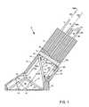
- FIG. 1is a cross-sectioned view of an optical switch according to one embodiment of the invention.
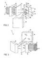
- FIG. 2is a perspective view of switching components of the switch
- FIG. 3is a perspective view from an opposing side of the switching components
- FIG. 4is a front view of a transmissive substrate having layers formed thereon, forming part of the switch;
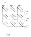
- FIG. 5is an electrical diagram of an array of photodetectors of the switch
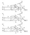
- FIG. 6is a cross-sectioned view of a switch, having transmissive components with a partially transmissive layer between inclined surfaces of the transmissive components, one of the transmissive components having a surface that causes convergence of light;
- FIG. 7is a cross-sectional view of a switch wherein a transmissive component thereof has a surface that causes both convergence and collimating of light;
- FIG. 8is a cross-sectional view of a switch wherein a surface of a propagated component thereof has a plurality of individual collimating lenses;
- FIG. 9is a cross-sectional side view of a mechanical construction of the switch of FIG. 8;
- FIG. 10is a cross-sectional side view of a mechanical construction of a switch having a transmissive housing
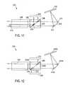
- FIG. 11is a cross-sectional view of a switch with two transmissive components that are secured to each other with beam splitting and reflective features between the transmissive components;
- FIG. 12is a cross-sectional view of a switch in which a light beam is detected after being reflected by an output pivoting mirror and before being coupled into an output optical fiber;
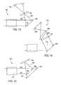
- FIG. 13is a cross-sectional view of a switch wherein a reflective substrate thereof is partially transmissive and input photodetectors are located behind the reflective substrate to detect functioning of an input pivoting mirror thereof;
- FIG. 14is a cross-sectional view of a switch having a reflective substrate that is also partially transmissive, a mapping lens, and input photodetectors located behind the mapping lens;
- FIG. 15is a cross-sectional view of a switch wherein input and output pivoting mirrors thereof are partially transmissive and input and output photodetectors are located behind the input and output pivoting mirrors.
- FIG. 1 of the accompanying drawingsillustrates an optical switch 10 according to an embodiment of the invention.
- the switch 10includes a plurality (other embodiments may have only one) of input optical fibers 12 (one of which is shown), a plurality (other embodiments may have only one) of output optical fibers 14 (only one of which is shown), switching components used to switch light from selected ones of the input optical fibers 12 to selected ones of the output optical fibers 14 , and monitoring components used to monitor operation of switching components.
- the switching componentsinclude a fiber block 16 , a lens plate 18 , a component housing 20 , a mirror array 22 , a transmissive mirror array cover 24 , and a reflective substrate 26 .
- each optical fiber 12 or 14is capable of carrying light with wavelengths from approximately 1100 nanometers (nm) to about 1700 nm. Light having a wavelength falling outside this range cannot be carried by the fibers 12 or 14 .
- the fiber block 16has a plurality of openings therethrough. Each optical fiber 12 or 14 is inserted into one side of the respective opening in the fiber block 16 until an end 30 thereof is located at an opposing side of the fiber block 16 .
- a plurality of collimating lenses 32are formed on the lens plate 18 .
- the lens plate 18is mounted to the fiber block 16 in a position wherein each collimating lens 32 is located over a respective end 30 of a respective optical fiber 12 or 14 on an opposing side of the lens plate 18 .
- fibers 12 or 14may be bonded to lens plate 18 or otherwise index matched.
- the switch housing 20includes a base 34 and a top portion 36 .
- the base 34is located on a reference surface and the top portion extends from the base 34 at an angle of approximately 55° with respect to reference.
- the lens plate 18is mounted to an upper end of the top portion 36 in a position wherein each one of the optical fibers 12 or 14 is located at an angle of approximately 55° with respect to reference. Other angles may work for other embodiments.
- the switchmay alternatively be designed such that the fibers are located at angles ranging from 45° to 70° to the reference.
- the mirror array 22includes a substrate 40 , a plurality of input pivoting mirrors 42 (one of which is shown), and a plurality of output pivoting mirrors 44 (one of which is shown).
- the mirror substrate 40is mounted to the base 34 such that the mirror substrate 40 extends in a reference plane.
- Each one of the pivoting mirrors 42 or 44is pivotally mounted to the mirror substrate 40 .
- Electrostatic actuators(not shown) are located in the mirror substrate 40 . A voltage can be applied to each one of the electrostatic actuators to cause pivoting of a respective pivoting mirror 42 or 44 .
- the reflective substrate 26has a reflective surface 48 .
- the reflective substrate 26is secured over an opening in the component housing 20 in a position wherein the reflective surface 48 is at approximately 35° relative to reference. This angle will normally be the complement of the fiber angle.
- the transmissive mirror array cover 24includes first and second panels 50 and 52 , respectively, which meet at an apex 54 .
- the transmissive mirror array cover 24is located over the mirror substrate 40 so that an enclosure 56 is defined between the panels 50 and 52 and the mirror substrate 40 .
- the enclosure 56is substantially sealed against ingress of contaminants so that the pivoting mirrors 42 and 44 are protected.
- the panels 50 and 52both have inner and outer surfaces that are inclined at approximately 35° with respect to reference, which angle is also complementary to the fiber angle.
- the monitoring componentsinclude a beam splitter 62 , a plurality of output optically splitting couplers 64 (one of which is shown), a plurality of monitoring optical fibers 66 (one of which is shown), and a photodetector array 68 .
- the beam splitter 62includes a transmissive substrate 70 having formed thereon a first, partially transmissive optical splitter mirror 72 and a second, entirely reflective mirror 74 .
- the optical splitter mirror 72 and the reflective mirror 74are located on the transmissive substrate 70 in positions wherein they do not block optical transmission through a transmissive portion 76 of the transmissive substrate 70 .
- the transmissive substrate 70is a planar substrate that is mounted to the component housing 20 at an angle that is approximately 45° with respect to a direction of an optical axis of the optical fibers 12 or 14 , with the optical splitter mirror 72 and the reflective mirror 74 located on the same side of the transmissive substrate 70 as the optical fibers 12 and 14 .
- the coupler 64is located on the output optical fiber 14 and the monitoring optical fiber 66 has one end also connected to the coupler 64 .
- An opposing end of the monitoring optical fiberis inserted through an opening in the fiber block 16 until an end 32 A thereof is located on an opposing side of the fiber block 16 . It will be understood that this arrangement schematically represents other equivalent paths that could be constructed by splitting fibers or joining them with connectors.
- Another collimating lens 32 Ais located on the lens plate 18 over the end 30 A.
- the photodetector array 68includes a photodetector array substrate 80 having formed thereon an input detector 82 and an output detector 84 .
- the photodetector array substrate 80is secured to the component housing over an opening thereof and extends at an angle that is at approximately 45° relative to the transmissive substrate 70 .
- the photodetector array 68is located on the same side of the transmissive substrate 70 as the optical splitter mirror 72 and the reflective mirror 74 .
- a light beam 100is propagated through the input optical fiber 12 and is radiated from the end 30 of the input optical fiber 12 through the lens plate 18 .
- the light beam 100then propagates through the collimating lens 32 located over the end 30 of the input optical fiber 12 , which collimates the light beam 100 .
- the light beam 100then propagates onto the optical splitter mirror 72 .
- the optical splitter mirror 72is partially transmissive and partially reflective so that an input propagated portion 102 of the light beam 100 propagates through the optical splitter mirror 72 and an input monitoring portion 104 is reflected by the optical splitter mirror 72 .
- the optical splitter mirrormay for example be 99% transmissive and 1% reflective so that the input propagated portion 102 comprises about 99% of the light beam 100 and the input monitoring portion 104 comprises about 1% of the light beam 100 .
- the input monitoring portion 104is propagated onto the input detector 82 .
- the input detector 82is a photodetector that generates a signal when light falls thereon so that a signal is generated when the input monitoring portion 104 falls onto the input detector 84 .
- the input propagated portion 102includes the entire range of wavelengths, i.e. from approximately 1100 nm to approximately 1700 nm, of the light.
- the input monitoring portion 104also includes the entire range of wavelengths, i.e. also from approximately 1100 nm to approximately 1700 nm.
- the input propagated portion 102propagates from the optical splitter mirror 72 through the transmissive substrate 70 and then through the top portion 36 of the component housing 20 onto the first panel 50 .
- the first panel 50has an outer inclined surface at a surface-light beam angle of approximately 90° relative to the input propagated portion 102 so that there is minimal distortion when the input propagated portion 102 propagates through the first panel 50 .
- the input propagated portion 102propagates through the first panel 50 onto the input pivoting mirror 42 , from where the input propagated portion 102 is reflected through the second panel 52 .
- Surfaces of the second panel 52are sufficiently close to normal to the output monitoring portion 102 when propagating therethrough so as to cause minimal distortion of the output monitoring portion 102 .
- the input propagated portion 102is then reflected by the reflective surface 48 back through the second panel 52 onto the output pivoting mirror 44 .
- the output pivoting mirror 44is shown, there are a plurality of output pivoting mirrors. Pivoting of the input pivoting mirror 42 allows for a change in the angle of the input propagated portion 102 reflected therefrom, with a corresponding change in the output pivoting mirror onto which the respective input propagated portion 102 falls.
- the input propagated portion 102then reflects off the respective output pivoting mirror 44 through the first panel 50 .
- the output pivoting mirror 44is pivoted so that the input propagated portion 102 being reflected thereby propagates at substantially right angles to the inclined surfaces of the first panel 50 .
- the input propagated portion 102then propagates through the transmissive portion 76 of the transmissive substrate 70 , whereafter the input propagated portion 102 is focused by one of the collimating lenses 32 and propagates through the lens plate 18 onto the end 30 of the output optical fiber 14 .
- only one output optical fiber 14is shown, there are a plurality of output optical fibers.
- the output pivoting mirror 44is pivoted so as to ensure that the input propagated portion 102 radiates in a direction in which the output optical fiber 14 extends from the end 30 thereof, thereby ensuring proper coupling of the input propagated portion 102 into the end of the output optical fiber 14 .
- a respective output pivoting mirroris typically aligned with each respective output optical fiber for this purpose.
- the coupler 64is located in the output optical fiber 14 and splits the input propagated portion 102 into an output propagated portion 105 and an output monitoring portion 106 .
- the output propagated portion 105is propagated from the coupler 64 through the output optical fiber 14 and the output monitoring portion 106 is propagated through the monitoring optical fiber 66 .
- the input propagated portion 102is typically split by the coupler 64 so that about 99% of the input propagated portion 102 (98% of the light beam 100 ) comprises the output propagated portion 105 and about 1% of the input propagated portion 102 (1% of the light beam 100 ) comprises the output monitoring portion 106 .
- the output propagated portion 105includes the entire range of wavelengths, i.e. from approximately 1100 nm to approximately 1700 nm, of the light.
- the output monitoring portion 106also includes the entire range of wavelengths, i.e. also from approximately 1100 nm to approximately 1700 nm.
- the output monitoring portion 106provides an indication of the output propagated portion 105 .
- a malfunction of the switching components of the switch 10can be detected by measuring the output monitoring portion 106 . It may, for example, occur that the input pivoting mirror 42 or the ouptut pivoting mirror 44 malfunction. Such a malfunction would then be detected by detecting the output monitoring portion 106 .
- the output monitoring portion 106will also provide an indication whether proper coupling of the input propagated portion 102 occurs at the end 30 of the output optical fiber 14 .
- the output monitoring portion 106is propagated through the monitoring optical fiber 66 and out of the end 30 A thereof, and from there through the lens plate 18 , whereafter the collimating lens 32 A collimates the output monitoring portion 106 .
- the output monitoring portion 106then propagates through the top portion 36 of the component housing 20 and is reflected by the reflective mirror 74 .
- the reflective mirror 74reflects the output monitoring portion 106 onto the output detector 84 .
- the output detector 84is also a photodetector like the input detector 82 , and converts the output monitoring portion 106 to an electrical signal.
- a comparisoncan be made between the light beam 100 and the output propagated portion 105 .
- Such a comparisoncan be used for controlling the pivoting mirrors 42 and 44 .
- FIGS. 2 and 3illustrate the operation of the switching components of the switch 10 in more detail.
- a plurality of input optical fibers 12 and a plurality of output optical fibers 14are provided.
- a respective collimating lensis located on the lens plate 18 over each one of the optical fibers 12 and 14 .
- An input pivoting mirror 42is located on the mirror substrate 40 in line with each one of the input optical fibers and an output pivoting mirror 44 is located in line with each one of the output optical fibers 14 .
- Each mirror 42 or 44can pivot about a respective first axis 108 and about a respective second axis 110 at right angles to the first axis 108 .
- FIGS. 2 and 3illustrate the plurality effect of the switching components of the switch 10 .
- the plurality effectalso applies to the monitoring components of the switch 10 .
- Each coupleris connected to a respective output optical fiber, each monitoring optical fiber is connected to a respective coupler, and a respective collimating lens is located over a respective end of a respective monitoring optical fiber.
- each input optical fiberpropagates a respective light beam.
- a respective light beamis separated into a respective input propagated portion and a respective input monitoring portion that is received by a respective input detector.
- a respective input propagated portionis separated by a respective coupler into a respective output propagated portion and a respective output monitoring portion.
- Each output monitoring portionis received by a respective output detector.
- FIG. 4illustrates the beam splitter arrangement 62 as it relates to the plurality effect.
- An entire area of the transmissive substrate 70 in line with ends of all of the input optical fibers 12is covered with the optical splitter mirror 72 .
- An entire area of the transmissive substrate 70 in line with ends of all the monitoring optical fibers 66is covered with the reflective mirror 74 .
- the transmissive portion 76covers an entire area over ends of all the output optical fibers 14 .
- FIG. 5illustrates an electrical circuit 100 including a plurality of photodetectors 82 and 84 , a plurality of sample lines 102 , and a plurality of output lines 104 .
- the photodetectors 82 and 84are located in rows and column. Each sample line 102 connects a respective column of the photodetectors 82 and 84 to one another and a respective output line 104 connects a respective row of the photodetectors to one another.
- Light shining, for example, on photodetector 82 Ais detected on output line named Vout 2 when a voltage is applied to sample line named Sample 2.
- Two reverse bias diodes 106are also located between a respective photodiode 82 or 84 and a respective output line 104 . The diodes 106 prevent flow of current through other photodiodes in the same column on which light does not fall.
- FIG. 6illustrates a switch 110 according to one alternative embodiment of the invention.
- the switch 110also includes a fiber block 116 , a reflective substrate 118 , a mirror substrate 120 , input pivoting mirrors 122 , output pivoting mirrors 124 , and a photodetector array 126 . These components are the same as in the embodiment of FIG. 1 .
- the switch 110further includes a first transparent component 130 and a second transparent component 132 .
- a partially transmissive mirror 134is formed in a layer on an inclined surface of the first transmissive sub-component 130 .
- An inclined surface of the second transmissive component 132is then located against the layer 134 and the second transmissive component 132 is secured to the first transmissive component 130 .
- the two components 130 and 132are located in a path of a light beam 136 such that the layer 134 is located at an angle of approximately 45° relative to a direction of the light beam 136 .
- a monitoring portion 138 of the light beam 136is reflected by the layer 134 towards the photodetector array 126 where it is received, and a propagated portion 140 of the light beam 136 is propagated through the layer 134 .
- the propagated portion 140then enters the second transmissive component 132 through the inclined surface behind the layer 134 , whereafter it propagates through the second transmissive component 132 , and then leaves the second transmissive component 132 through a second surface 144 thereof.
- the second surface 144has two inclined sections 146 and 148 respectively.
- the section 146is at an angle between 0° and approximately 90° with respect to the propagated portion 140 before it leaves the section 146
- the second section 148is at an angle between approximately 90° and 180° with respect to the propagated portion 140 before it enters the section 148 . Because the sections 146 and 148 are inclined, the propagated portion 140 converges in a direction away from the surface 144 towards the pivoting mirrors 122 and 124 . Although only one light beam is shown, there are a plurality of light beams. Each respective light beam first passes through the first section 146 and then passes through the second section 148 .
- FIG. 7illustrates a switch 150 that is a modification of the switch 110 of FIG. 6 .
- the switch 150has a first transmissive component 152 having a second surface 154 that is curved.
- the curvature of the surface 154makes provision for collimating of a light beam 136 and for convergence of a propagated portion 140 of the light beam 136 in a direction from the surface 154 towards pivoting mirrors 122 and 124 .
- the switches 150 of FIG. 7 and 110 of FIG. 6substantially are the same in other respects.
- FIG. 8illustrates a switch 160 that is a modification of the switch 150 of FIG. 7 .
- the switch 160has a second transmissive component 162 with a second surface 164 having a plurality of individual collimating lenses 166 formed thereon.
- a light beam 136passes through one of the collimating lenses 166 upon exiting from the second transmissive component 162 , and then passes through another one of the collimating lenses 166 upon entering into the second transmissive component 162 .
- the surface 164has an intended advantage that the collimating nature of the collimating lenses 166 can be designed independently of the convergence effect of the surface 164 .
- FIG. 9illustrates the mechanical construction of the switch 160 of FIG. 8 .
- the switch 160includes a housing 170 but only includes a base such as the base 34 of the switch 10 of FIG. 1 and no top portion. Instead, the second transmissive component 162 is mounted directly over an opening of the housing 170 .
- FIG. 9also shows that the mirror substrate 120 is mounted to a package substrate 172 . A plurality of solder balls 174 are located on a lower surface of the substrate 172 , through which signals can be provided to the mirror substrate 120 .
- FIG. 10illustrates a switch 180 according to a further embodiment of the invention having a transparent housing 182 .
- the transparent housing 182has two outer surfaces 184 and 186 that meet at an apex and are both inclined relative to a plane of a mirror substrate 190 .
- Two transmissive components 192 and 194 with a partially transmissive mirror layer between themare mounted to the inclined surface 184 .
- a reflective substrate 194is secured to the surface 186 .
- An intended advantage of the switch 180is that the housing 182 provides protection against contaminants that may land on mirrors on the mirror substrate 190 .
- the switch 180 of FIG. 10is substantially the same as the switch 160 of FIG. 9 in other respects.
- FIG. 11illustrates a switch 200 similar to the switch 10 of FIG.
- FIG. 1which, instead of the top portion 36 and the transmissive substrate 70 of the switch 10 of including FIG. 1, includes first and second transmissive components 202 and 204 .
- An optical splitter mirror 206 and a reflective mirror 208are located between inclined surfaces of the transparent components 202 and 204 .
- the switch 200operates in substantially the same manner as the switch 10 of FIG. 1 and also includes a fiber block 208 , a photodetector array 210 , a mirror substrate 212 , pivoting mirrors 214 , a reflective substrate 216 , and optical couplers 218 operate in a similar manner. No lens plate is provided, but a surface of the second transmissive substrate may be profiled such as in FIG. 6, FIG. 7, or FIG. 8 .
- FIG. 12illustrates a switch 230 according to a further embodiment of the invention.
- the switch 230is similar to the switch 200 , except that no provision is made for optical couplers and monitoring optical fibers. Instead, a second optical splitter mirror 232 is located between inclined surfaces of transparent components 202 A and 204 A. The optical splitter mirror 232 is located in a path of a light beam exiting the switch 230 —i.e., after being reflected by pivoting mirrors 214 A and a reflective substrate 216 A. An output reflected portion 234 is propagated to a photodetector array 236 located on a side of the switch that is opposite from a photo-detect array 210 A, which detects an input monitoring portion.
- the monitoring portion 234 of switch 230 of FIG. 12does not provide a direct measurement of coupling of a light beam into an output fiber in a lens block 240 thereof.
- FIG. 13illustrates a switch 250 according to a further embodiment of the invention, wherein a reflective substrate 252 thereof is also partially transmissive.
- An output detector 254is located behind the reflective substrate 252 to detect light being reflected from an input pivoting mirror.
- An electric signal generated by the photodetector 254provides an indication of a propagated portion 258 of a light beam 260 , the propagated portion 258 being propagated to an output pivoting mirror 262 .
- the functioning of the input pivoting mirror 256can be monitored, although the functioning of the output pivoting mirror 262 is not be monitored.
- FIG. 14illustrates a switch 270 that provides an indication of a light beam 272 before being reflected by an input pivoting mirror 274 .
- a mapping lens 276is located between a partially transmissive reflective substrate 278 and an input photodetector 280 on a detector substrate.
- a monitoring portion 282 of the light beam 272is received by the input detector 280 regardless of the orientation of the input mirror 274 .
- a malfunction in the mirror 274would thus go undetected. This differs from the way the switch 250 of FIG. 13 functions. In the switch 250 , light only falls on the output detector 254 if the input pivoting mirror 256 is in a selected orientation and not when the input pivoting mirror 256 is rotated out of the selected orientation.
- FIG. 15illustrates a switch 290 according to a further embodiment of the invention, which allows for detection of both a light beam 292 before being reflected by an input pivoting mirror 294 and detection of a propagated portion 296 of the light beam 292 after being reflected by the input pivoting mirror 294 but before being reflected by an output pivoting mirror 298 .
- the pivoting mirrors 294 and 298are partially transmissive. When the light beam 292 falls on the input pivoting mirror 294 , a propagated portion 296 of the light beam 292 is reflected by the input pivoting mirror 294 . An input monitoring portion passes through the input pivoting mirror 294 onto an input detector 300 located on a detector substrate behind the input pivoting mirror 294 .
- the input propagated portion 296is reflected by a reflective substrate 302 towards the output pivoting mirror 298 .
- An output propagated portion 304is reflected by the output pivoting mirror 298 and an output monitoring portion propagates through the output pivoting mirror 298 onto an output photodetector 306 located on the same detector substrate as the input detector 300 .
- An electric signal generated by the input detector 300provides an indication of the light beam 292 regardless of the orientation of the input pivoting mirror 294 .
- An electric signal generated by the output detector 306depends on the direction on which the input propagated portion 296 is reflected by the input pivoting mirror 294 , and thus provides an indication of the functioning of the input pivoting mirror 294 .
- the switch 290does not provide an indication of the functioning of the output pivoting mirror 298 . Incorrect pivoting of the output pivoting mirror 298 could result in the output propagated portion 304 not being coupled into the correct output optical fiber in a fiber block 310 , and would go undetected.
Landscapes
- Physics & Mathematics (AREA)
- General Physics & Mathematics (AREA)
- Optics & Photonics (AREA)
- Mechanical Light Control Or Optical Switches (AREA)
Abstract
Description
Claims (56)
Priority Applications (1)
| Application Number | Priority Date | Filing Date | Title |
|---|---|---|---|
| US09/805,528US6792177B2 (en) | 2001-03-12 | 2001-03-12 | Optical switch with internal monitoring |
Applications Claiming Priority (1)
| Application Number | Priority Date | Filing Date | Title |
|---|---|---|---|
| US09/805,528US6792177B2 (en) | 2001-03-12 | 2001-03-12 | Optical switch with internal monitoring |
Publications (2)
| Publication Number | Publication Date |
|---|---|
| US20020126949A1 US20020126949A1 (en) | 2002-09-12 |
| US6792177B2true US6792177B2 (en) | 2004-09-14 |
Family
ID=25191808
Family Applications (1)
| Application Number | Title | Priority Date | Filing Date |
|---|---|---|---|
| US09/805,528Expired - LifetimeUS6792177B2 (en) | 2001-03-12 | 2001-03-12 | Optical switch with internal monitoring |
Country Status (1)
| Country | Link |
|---|---|
| US (1) | US6792177B2 (en) |
Cited By (15)
| Publication number | Priority date | Publication date | Assignee | Title |
|---|---|---|---|---|
| US20030026524A1 (en)* | 2001-08-06 | 2003-02-06 | Sunao Kakizaki | Optical switching apparatus with optical reflection monitor and reflection monitoring system |
| US20030185488A1 (en)* | 2002-04-02 | 2003-10-02 | Calient Networks, Inc. | Optical amplification in photonic switched crossconnect systems |
| US20040047547A1 (en)* | 2002-09-10 | 2004-03-11 | Yakov Reznichenko | Two input, two output optical switch using two movable mirrors |
| US6978061B1 (en)* | 2004-10-08 | 2005-12-20 | Fujitsu Limited | Optical switching device |
| US20080002932A1 (en)* | 2006-06-19 | 2008-01-03 | Xuezhe Zheng | Method and Apparatus to Provide Multi-Channel Bulk Fiber Optical Power Detection |
| US20090028502A1 (en)* | 2006-11-07 | 2009-01-29 | Harry Wayne Presley | Segmented prism element and associated methods for manifold fiberoptic switches |
| US20090103861A1 (en)* | 2006-11-07 | 2009-04-23 | Olympus Microsystems America, Inc. | Beam steering element and associated methods for manifold fiberoptic switches |
| US20090110349A1 (en)* | 2006-11-07 | 2009-04-30 | Olympus Microsystems America, Inc | Beam steering element and associated methods for mixed manifold fiberoptic switches |
| US20090220233A1 (en)* | 2008-02-28 | 2009-09-03 | Olympus Corporation | Wavelength selective switch having distinct planes of operation |
| US20090232446A1 (en)* | 2006-11-07 | 2009-09-17 | Olympus Corporation | High port count instantiated wavelength selective switch |
| US20090231580A1 (en)* | 2006-11-07 | 2009-09-17 | Olympus Corporation | Beam steering element and associated methods for manifold fiberoptic switches and monitoring |
| US20090304328A1 (en)* | 2006-11-07 | 2009-12-10 | Olympus Microsystems America, Inc. | Beam steering element and associated methods for manifold fiberoptic switches and monitoring |
| US8682117B1 (en)* | 2013-08-05 | 2014-03-25 | Calient Technologies, Inc. | Making lightless connections in an optical circuit switch |
| US9213143B1 (en) | 2014-07-02 | 2015-12-15 | Calient Technologies, Inc. | Making connections through an optical circuit switch |
| US9590998B2 (en) | 2014-07-02 | 2017-03-07 | Calient Technologies, Inc. | Network switch with hierarchical security |
Families Citing this family (5)
| Publication number | Priority date | Publication date | Assignee | Title |
|---|---|---|---|---|
| US6931170B2 (en)* | 2002-10-18 | 2005-08-16 | Analog Devices, Inc. | Fiber-attached optical devices with in-plane micromachined mirrors |
| JP2005157163A (en)* | 2003-11-28 | 2005-06-16 | Sumitomo Electric Ind Ltd | Optical device |
| US7315672B2 (en)* | 2003-11-28 | 2008-01-01 | Sumitomo Electric Industries, Ltd. | Optical device |
| JP4627627B2 (en)* | 2004-03-31 | 2011-02-09 | 富士通株式会社 | Micromirror element and optical switch |
| US7541776B2 (en)* | 2004-12-10 | 2009-06-02 | Apple Inc. | Method and system for operating a portable electronic device in a power-limited manner |
Citations (81)
| Publication number | Priority date | Publication date | Assignee | Title |
|---|---|---|---|---|
| US3492484A (en) | 1965-12-15 | 1970-01-27 | Nippon Electric Co | Space division multiplexed optical communication system including a pair of light responsive matrices |
| US3649105A (en) | 1968-02-21 | 1972-03-14 | North American Rockwell | Optical shutter |
| US4208094A (en) | 1978-10-02 | 1980-06-17 | Bell Telephone Laboratories, Incorporated | Optical switch |
| US4243297A (en) | 1979-06-27 | 1981-01-06 | International Communications And Energy, Inc. | Optical wavelength division multiplexer mixer-splitter |
| US4365863A (en) | 1979-05-30 | 1982-12-28 | Le Materiel Telephonique Thomson-Csf | Optical switch for a very large number of channels |
| US4498730A (en) | 1978-03-10 | 1985-02-12 | Matsushita Electric Industrial Co., Ltd. | Optical switching device |
| JPS60107017A (en) | 1983-11-16 | 1985-06-12 | Hitachi Ltd | light deflection element |
| US4626066A (en) | 1983-12-30 | 1986-12-02 | At&T Bell Laboratories | Optical coupling device utilizing a mirror and cantilevered arm |
| GB2175705A (en) | 1985-05-24 | 1986-12-03 | Stc Plc | Dirigible reflector and mounting made of single crystal material |
| US4848999A (en) | 1987-10-13 | 1989-07-18 | Texas A & M University System | Method for producing reflective taps in optical fibers and applications thereof |
| US4892388A (en) | 1987-10-13 | 1990-01-09 | Texas A & M University System | Method for producing reflective taps in optical fibers and applications thereof |
| US4923273A (en) | 1987-10-13 | 1990-05-08 | Texas A&M University System | Method for producing reflective taps in optical fibers and applications thereof |
| US4941724A (en) | 1988-08-29 | 1990-07-17 | International Business Machines Corporation | Optical fiber connection utilizing photodiode means |
| US5083857A (en) | 1990-06-29 | 1992-01-28 | Texas Instruments Incorporated | Multi-level deformable mirror device |
| US5097354A (en) | 1989-07-27 | 1992-03-17 | Omron Corporation | Beam scanner |
| US5172262A (en) | 1985-10-30 | 1992-12-15 | Texas Instruments Incorporated | Spatial light modulator and method |
| US5204922A (en) | 1991-10-22 | 1993-04-20 | Puritan-Bennett Corporation | Optical signal channel selector |
| JPH05107485A (en) | 1991-10-18 | 1993-04-30 | Nippon Telegr & Teleph Corp <Ntt> | Optical connection module |
| US5235187A (en) | 1991-05-14 | 1993-08-10 | Cornell Research Foundation | Methods of fabricating integrated, aligned tunneling tip pairs |
| JPH06180428A (en) | 1992-12-15 | 1994-06-28 | Matsushita Electric Ind Co Ltd | Electrostatically driven compact optical scanner |
| GB2275787A (en) | 1993-03-05 | 1994-09-07 | British Aerospace | Silicon micro-mirror unit |
| US5444566A (en) | 1994-03-07 | 1995-08-22 | Texas Instruments Incorporated | Optimized electronic operation of digital micromirror devices |
| US5450512A (en) | 1993-04-12 | 1995-09-12 | Matsushita Electric Industrial Co., Ltd. | Optical tap |
| US5488862A (en) | 1993-10-18 | 1996-02-06 | Armand P. Neukermans | Monolithic silicon rate-gyro with integrated sensors |
| US5524153A (en) | 1995-02-10 | 1996-06-04 | Astarte Fiber Networks, Inc. | Optical fiber switching system and method using same |
| US5555558A (en) | 1994-05-27 | 1996-09-10 | Laughlin; Richard H. | Method for switching optical signals |
| US5555330A (en) | 1994-12-21 | 1996-09-10 | E-Tek Dynamics, Inc. | Wavelength division multiplexed coupler with low crosstalk between channels and integrated coupler/isolator device |
| US5608468A (en) | 1993-07-14 | 1997-03-04 | Texas Instruments Incorporated | Method and device for multi-format television |
| US5629790A (en) | 1993-10-18 | 1997-05-13 | Neukermans; Armand P. | Micromachined torsional scanner |
| US5661591A (en) | 1995-09-29 | 1997-08-26 | Texas Instruments Incorporated | Optical switch having an analog beam for steering light |
| US5673139A (en) | 1993-07-19 | 1997-09-30 | Medcom, Inc. | Microelectromechanical television scanning device and method for making the same |
| US5726073A (en) | 1993-06-01 | 1998-03-10 | Cornell Research Foundation, Inc. | Compound stage MEM actuator suspended for multidimensional motion |
| EP0834759A2 (en) | 1996-09-27 | 1998-04-08 | Mcnc | Microelectromechanical devices including rotating plates and related methods |
| US5808780A (en) | 1997-06-09 | 1998-09-15 | Texas Instruments Incorporated | Non-contacting micromechanical optical switch |
| US5872880A (en) | 1996-08-12 | 1999-02-16 | Ronald S. Maynard | Hybrid-optical multi-axis beam steering apparatus |
| GB2328312A (en) | 1997-08-14 | 1999-02-17 | John Quentin Phillipps | Mirror controlled display device |
| EP0916983A1 (en) | 1997-11-15 | 1999-05-19 | Canon Kabushiki Kaisha | Light deflection device and array thereof |
| US5912608A (en) | 1995-05-26 | 1999-06-15 | The Nippon Signal Co., Ltd. | Planar type electromagnetic actuator |
| DE19757181A1 (en) | 1997-12-19 | 1999-07-01 | Bosch Gmbh Robert | Arrangement for coupling glass fibers |
| US5943157A (en) | 1997-05-08 | 1999-08-24 | Texas Instruments Incorporated | Spatial light modulator having improved contrast ratio |
| US5943454A (en) | 1997-08-15 | 1999-08-24 | Lucent Technologies, Inc. | Freespace optical bypass-exchange switch |
| US5960133A (en) | 1998-01-27 | 1999-09-28 | Tellium, Inc. | Wavelength-selective optical add/drop using tilting micro-mirrors |
| US5960132A (en) | 1997-09-09 | 1999-09-28 | At&T Corp. | Fiber-optic free-space micromachined matrix switches |
| US5982554A (en) | 1997-12-31 | 1999-11-09 | At&T Corp | Bridging apparatus and method for an optical crossconnect device |
| US5999303A (en) | 1997-03-24 | 1999-12-07 | Seagate Technology Inc. | Micro-machined mirror using tethered elements |
| US6002818A (en) | 1997-12-05 | 1999-12-14 | Lucent Technologies Inc | Free-space optical signal switch arrangement |
| US6005998A (en) | 1998-02-20 | 1999-12-21 | Lucent Technologies Inc. | Strictly non-blocking scalable matrix optical switch |
| WO1999066354A2 (en) | 1998-06-05 | 1999-12-23 | Astarte Fiber Networks, Inc. | Planar array optical switch and method |
| US6009219A (en) | 1996-04-08 | 1999-12-28 | Axiom Analytical Incorporated | Optical beam switching device |
| WO1999067666A1 (en) | 1998-06-05 | 1999-12-29 | Astarte Fiber Networks, Inc. | Mirror based fiber optic switch and control system |
| JP2000019434A (en) | 1998-06-30 | 2000-01-21 | Nippon Signal Co Ltd:The | Optical selector |
| EP0980014A1 (en) | 1998-06-02 | 2000-02-16 | Texas Instruments Incorporated | Spring-ring micromechanical device |
| US6040935A (en) | 1999-01-25 | 2000-03-21 | The United States Of America As Represented By The Secretary Of The Air Force | Flexureless multi-stable micromirrors for optical switching |
| US6044705A (en) | 1993-10-18 | 2000-04-04 | Xros, Inc. | Micromachined members coupled for relative rotation by torsion bars |
| US6049412A (en) | 1998-09-22 | 2000-04-11 | Lucent Technologies, Inc. | Reflective Faraday-based optical devices including an optical monitoring tap |
| WO2000020899A2 (en) | 1998-09-15 | 2000-04-13 | Xros, Inc. | Flexible, modular, compact fiber optic switch |
| US6072617A (en) | 1996-11-26 | 2000-06-06 | Texas Instruments Incorporated | Micro mechanical device with memory metal component |
| US6075639A (en) | 1997-10-22 | 2000-06-13 | The Board Of Trustees Of The Leland Stanford Junior University | Micromachined scanning torsion mirror and method |
| US6075239A (en) | 1997-09-10 | 2000-06-13 | Lucent Technologies, Inc. | Article comprising a light-actuated micromechanical photonic switch |
| US6097860A (en) | 1998-06-05 | 2000-08-01 | Astarte Fiber Networks, Inc. | Compact optical matrix switch with fixed location fibers |
| US6097858A (en) | 1998-06-05 | 2000-08-01 | Astarte Fiber Networks, Inc. | Sensing configuration for fiber optic switch control system |
| US6097859A (en) | 1998-02-12 | 2000-08-01 | The Regents Of The University Of California | Multi-wavelength cross-connect optical switch |
| US6101299A (en) | 1998-06-05 | 2000-08-08 | Astarte Fiber Networks, Inc. | Optical switch targeting system |
| US6201622B1 (en) | 1995-03-24 | 2001-03-13 | British Telecommunications Public Limited Company | Optical network |
| US6201631B1 (en) | 1999-10-08 | 2001-03-13 | Lucent Technologies Inc. | Process for fabricating an optical mirror array |
| US6208784B1 (en) | 1998-12-07 | 2001-03-27 | Multiplex Raceway Systems, Inc. | Fiber optic multiple access system |
| WO2001033898A2 (en) | 1999-11-02 | 2001-05-10 | Xros, Inc. | An optical cross-connect switching system |
| US6236481B1 (en) | 1999-06-09 | 2001-05-22 | Astarte Fiber Networks, Inc. | Method and apparatus for providing loss equalization and adjustment in a fiber optic network |
| US6245590B1 (en) | 1999-08-05 | 2001-06-12 | Microvision Inc. | Frequency tunable resonant scanner and method of making |
| US6249626B1 (en) | 1998-03-06 | 2001-06-19 | Lucent Technologies, Inc. | Multimode fiber optical power monitoring tap for optical transmission systems |
| US6253001B1 (en) | 2000-01-20 | 2001-06-26 | Agilent Technologies, Inc. | Optical switches using dual axis micromirrors |
| US6256430B1 (en) | 1998-11-23 | 2001-07-03 | Agere Systems Inc. | Optical crossconnect system comprising reconfigurable light-reflecting devices |
| US6262827B1 (en) | 1999-06-29 | 2001-07-17 | Fujitsu Limited | Galvano-mirror |
| EP1120677A2 (en) | 2000-01-21 | 2001-08-01 | Cronos Integrated Microsystems, Inc. | MEMS optical cross-connect switch |
| US6278812B1 (en) | 1998-12-14 | 2001-08-21 | At&T Corporation | Protection schemes for mirror-failure in free-space micromachined optical switches |
| US6295154B1 (en) | 1998-06-05 | 2001-09-25 | Texas Instruments Incorporated | Optical switching apparatus |
| US6320993B1 (en) | 1998-06-05 | 2001-11-20 | Astarte Fiber Networks, Inc. | Optical switch pathway configuration using control signals |
| US6330102B1 (en) | 2000-03-24 | 2001-12-11 | Onix Microsystems | Apparatus and method for 2-dimensional steered-beam NxM optical switch using single-axis mirror arrays and relay optics |
| US6396976B1 (en) | 1999-04-15 | 2002-05-28 | Solus Micro Technologies, Inc. | 2D optical switch |
| US6549692B1 (en)* | 2001-02-13 | 2003-04-15 | Tellium, Inc. | Optical monitoring of the angular position of micro mirrors in an optical switch |
| US6549691B1 (en)* | 2000-11-08 | 2003-04-15 | Xerox Corporation | Optical cross switching system |
- 2001
- 2001-03-12USUS09/805,528patent/US6792177B2/ennot_activeExpired - Lifetime
Patent Citations (89)
| Publication number | Priority date | Publication date | Assignee | Title |
|---|---|---|---|---|
| US3492484A (en) | 1965-12-15 | 1970-01-27 | Nippon Electric Co | Space division multiplexed optical communication system including a pair of light responsive matrices |
| US3649105A (en) | 1968-02-21 | 1972-03-14 | North American Rockwell | Optical shutter |
| US4498730A (en) | 1978-03-10 | 1985-02-12 | Matsushita Electric Industrial Co., Ltd. | Optical switching device |
| US4208094A (en) | 1978-10-02 | 1980-06-17 | Bell Telephone Laboratories, Incorporated | Optical switch |
| US4365863A (en) | 1979-05-30 | 1982-12-28 | Le Materiel Telephonique Thomson-Csf | Optical switch for a very large number of channels |
| US4243297A (en) | 1979-06-27 | 1981-01-06 | International Communications And Energy, Inc. | Optical wavelength division multiplexer mixer-splitter |
| JPS60107017A (en) | 1983-11-16 | 1985-06-12 | Hitachi Ltd | light deflection element |
| US4626066A (en) | 1983-12-30 | 1986-12-02 | At&T Bell Laboratories | Optical coupling device utilizing a mirror and cantilevered arm |
| GB2175705A (en) | 1985-05-24 | 1986-12-03 | Stc Plc | Dirigible reflector and mounting made of single crystal material |
| US5172262A (en) | 1985-10-30 | 1992-12-15 | Texas Instruments Incorporated | Spatial light modulator and method |
| US4892388A (en) | 1987-10-13 | 1990-01-09 | Texas A & M University System | Method for producing reflective taps in optical fibers and applications thereof |
| US4923273A (en) | 1987-10-13 | 1990-05-08 | Texas A&M University System | Method for producing reflective taps in optical fibers and applications thereof |
| US4848999A (en) | 1987-10-13 | 1989-07-18 | Texas A & M University System | Method for producing reflective taps in optical fibers and applications thereof |
| US4941724A (en) | 1988-08-29 | 1990-07-17 | International Business Machines Corporation | Optical fiber connection utilizing photodiode means |
| US5097354A (en) | 1989-07-27 | 1992-03-17 | Omron Corporation | Beam scanner |
| US5083857A (en) | 1990-06-29 | 1992-01-28 | Texas Instruments Incorporated | Multi-level deformable mirror device |
| US5600383A (en) | 1990-06-29 | 1997-02-04 | Texas Instruments Incorporated | Multi-level deformable mirror device with torsion hinges placed in a layer different from the torsion beam layer |
| US5235187A (en) | 1991-05-14 | 1993-08-10 | Cornell Research Foundation | Methods of fabricating integrated, aligned tunneling tip pairs |
| JPH05107485A (en) | 1991-10-18 | 1993-04-30 | Nippon Telegr & Teleph Corp <Ntt> | Optical connection module |
| US5204922A (en) | 1991-10-22 | 1993-04-20 | Puritan-Bennett Corporation | Optical signal channel selector |
| JPH06180428A (en) | 1992-12-15 | 1994-06-28 | Matsushita Electric Ind Co Ltd | Electrostatically driven compact optical scanner |
| GB2275787A (en) | 1993-03-05 | 1994-09-07 | British Aerospace | Silicon micro-mirror unit |
| US5450512A (en) | 1993-04-12 | 1995-09-12 | Matsushita Electric Industrial Co., Ltd. | Optical tap |
| US5726073A (en) | 1993-06-01 | 1998-03-10 | Cornell Research Foundation, Inc. | Compound stage MEM actuator suspended for multidimensional motion |
| US5608468A (en) | 1993-07-14 | 1997-03-04 | Texas Instruments Incorporated | Method and device for multi-format television |
| US5920417A (en) | 1993-07-19 | 1999-07-06 | Medcam, Inc. | Microelectromechanical television scanning device and method for making the same |
| US5920417C1 (en) | 1993-07-19 | 2002-04-02 | Medcam Inc | Microelectromechanical television scanning device and method for making the same |
| US5673139A (en) | 1993-07-19 | 1997-09-30 | Medcom, Inc. | Microelectromechanical television scanning device and method for making the same |
| US5648618A (en) | 1993-10-18 | 1997-07-15 | Armand P. Neukermans | Micromachined hinge having an integral torsion sensor |
| US5629790A (en) | 1993-10-18 | 1997-05-13 | Neukermans; Armand P. | Micromachined torsional scanner |
| US5488862A (en) | 1993-10-18 | 1996-02-06 | Armand P. Neukermans | Monolithic silicon rate-gyro with integrated sensors |
| US6044705A (en) | 1993-10-18 | 2000-04-04 | Xros, Inc. | Micromachined members coupled for relative rotation by torsion bars |
| US5444566A (en) | 1994-03-07 | 1995-08-22 | Texas Instruments Incorporated | Optimized electronic operation of digital micromirror devices |
| US5555558A (en) | 1994-05-27 | 1996-09-10 | Laughlin; Richard H. | Method for switching optical signals |
| US5555330A (en) | 1994-12-21 | 1996-09-10 | E-Tek Dynamics, Inc. | Wavelength division multiplexed coupler with low crosstalk between channels and integrated coupler/isolator device |
| US5524153A (en) | 1995-02-10 | 1996-06-04 | Astarte Fiber Networks, Inc. | Optical fiber switching system and method using same |
| US6201622B1 (en) | 1995-03-24 | 2001-03-13 | British Telecommunications Public Limited Company | Optical network |
| US5912608A (en) | 1995-05-26 | 1999-06-15 | The Nippon Signal Co., Ltd. | Planar type electromagnetic actuator |
| US5661591A (en) | 1995-09-29 | 1997-08-26 | Texas Instruments Incorporated | Optical switch having an analog beam for steering light |
| US6009219A (en) | 1996-04-08 | 1999-12-28 | Axiom Analytical Incorporated | Optical beam switching device |
| US6137926A (en) | 1996-08-12 | 2000-10-24 | Maynard; Ronald S. | Hybrid optical multi-axis beam steering apparatus |
| US5872880A (en) | 1996-08-12 | 1999-02-16 | Ronald S. Maynard | Hybrid-optical multi-axis beam steering apparatus |
| EP0834759A2 (en) | 1996-09-27 | 1998-04-08 | Mcnc | Microelectromechanical devices including rotating plates and related methods |
| US6072617A (en) | 1996-11-26 | 2000-06-06 | Texas Instruments Incorporated | Micro mechanical device with memory metal component |
| US6289145B1 (en) | 1997-02-13 | 2001-09-11 | The Regents Of The University Of California | Multi-wavelength cross-connect optical switch |
| US5999303A (en) | 1997-03-24 | 1999-12-07 | Seagate Technology Inc. | Micro-machined mirror using tethered elements |
| US5943157A (en) | 1997-05-08 | 1999-08-24 | Texas Instruments Incorporated | Spatial light modulator having improved contrast ratio |
| US5808780A (en) | 1997-06-09 | 1998-09-15 | Texas Instruments Incorporated | Non-contacting micromechanical optical switch |
| GB2328312A (en) | 1997-08-14 | 1999-02-17 | John Quentin Phillipps | Mirror controlled display device |
| US5943454A (en) | 1997-08-15 | 1999-08-24 | Lucent Technologies, Inc. | Freespace optical bypass-exchange switch |
| US5960132A (en) | 1997-09-09 | 1999-09-28 | At&T Corp. | Fiber-optic free-space micromachined matrix switches |
| US6075239A (en) | 1997-09-10 | 2000-06-13 | Lucent Technologies, Inc. | Article comprising a light-actuated micromechanical photonic switch |
| US6075639A (en) | 1997-10-22 | 2000-06-13 | The Board Of Trustees Of The Leland Stanford Junior University | Micromachined scanning torsion mirror and method |
| EP0916983A1 (en) | 1997-11-15 | 1999-05-19 | Canon Kabushiki Kaisha | Light deflection device and array thereof |
| US6002818A (en) | 1997-12-05 | 1999-12-14 | Lucent Technologies Inc | Free-space optical signal switch arrangement |
| DE19757181A1 (en) | 1997-12-19 | 1999-07-01 | Bosch Gmbh Robert | Arrangement for coupling glass fibers |
| US5982554A (en) | 1997-12-31 | 1999-11-09 | At&T Corp | Bridging apparatus and method for an optical crossconnect device |
| US5960133A (en) | 1998-01-27 | 1999-09-28 | Tellium, Inc. | Wavelength-selective optical add/drop using tilting micro-mirrors |
| US6097859A (en) | 1998-02-12 | 2000-08-01 | The Regents Of The University Of California | Multi-wavelength cross-connect optical switch |
| US6005998A (en) | 1998-02-20 | 1999-12-21 | Lucent Technologies Inc. | Strictly non-blocking scalable matrix optical switch |
| US6249626B1 (en) | 1998-03-06 | 2001-06-19 | Lucent Technologies, Inc. | Multimode fiber optical power monitoring tap for optical transmission systems |
| EP0980014A1 (en) | 1998-06-02 | 2000-02-16 | Texas Instruments Incorporated | Spring-ring micromechanical device |
| US6466711B1 (en)* | 1998-06-05 | 2002-10-15 | Afn, Llc | Planar array optical switch and method |
| US6097858A (en) | 1998-06-05 | 2000-08-01 | Astarte Fiber Networks, Inc. | Sensing configuration for fiber optic switch control system |
| US6097860A (en) | 1998-06-05 | 2000-08-01 | Astarte Fiber Networks, Inc. | Compact optical matrix switch with fixed location fibers |
| US6101299A (en) | 1998-06-05 | 2000-08-08 | Astarte Fiber Networks, Inc. | Optical switch targeting system |
| US6320993B1 (en) | 1998-06-05 | 2001-11-20 | Astarte Fiber Networks, Inc. | Optical switch pathway configuration using control signals |
| WO1999067666A1 (en) | 1998-06-05 | 1999-12-29 | Astarte Fiber Networks, Inc. | Mirror based fiber optic switch and control system |
| US6295154B1 (en) | 1998-06-05 | 2001-09-25 | Texas Instruments Incorporated | Optical switching apparatus |
| WO1999066354A2 (en) | 1998-06-05 | 1999-12-23 | Astarte Fiber Networks, Inc. | Planar array optical switch and method |
| JP2000019434A (en) | 1998-06-30 | 2000-01-21 | Nippon Signal Co Ltd:The | Optical selector |
| WO2000020899A2 (en) | 1998-09-15 | 2000-04-13 | Xros, Inc. | Flexible, modular, compact fiber optic switch |
| US6049412A (en) | 1998-09-22 | 2000-04-11 | Lucent Technologies, Inc. | Reflective Faraday-based optical devices including an optical monitoring tap |
| US6256430B1 (en) | 1998-11-23 | 2001-07-03 | Agere Systems Inc. | Optical crossconnect system comprising reconfigurable light-reflecting devices |
| US6208784B1 (en) | 1998-12-07 | 2001-03-27 | Multiplex Raceway Systems, Inc. | Fiber optic multiple access system |
| US6278812B1 (en) | 1998-12-14 | 2001-08-21 | At&T Corporation | Protection schemes for mirror-failure in free-space micromachined optical switches |
| US6040935A (en) | 1999-01-25 | 2000-03-21 | The United States Of America As Represented By The Secretary Of The Air Force | Flexureless multi-stable micromirrors for optical switching |
| US6396976B1 (en) | 1999-04-15 | 2002-05-28 | Solus Micro Technologies, Inc. | 2D optical switch |
| US6236481B1 (en) | 1999-06-09 | 2001-05-22 | Astarte Fiber Networks, Inc. | Method and apparatus for providing loss equalization and adjustment in a fiber optic network |
| US6262827B1 (en) | 1999-06-29 | 2001-07-17 | Fujitsu Limited | Galvano-mirror |
| US6245590B1 (en) | 1999-08-05 | 2001-06-12 | Microvision Inc. | Frequency tunable resonant scanner and method of making |
| US6201631B1 (en) | 1999-10-08 | 2001-03-13 | Lucent Technologies Inc. | Process for fabricating an optical mirror array |
| WO2001033898A2 (en) | 1999-11-02 | 2001-05-10 | Xros, Inc. | An optical cross-connect switching system |
| US6253001B1 (en) | 2000-01-20 | 2001-06-26 | Agilent Technologies, Inc. | Optical switches using dual axis micromirrors |
| US6396975B1 (en) | 2000-01-21 | 2002-05-28 | Jds Uniphase Corporation | MEMS optical cross-connect switch |
| EP1120677A2 (en) | 2000-01-21 | 2001-08-01 | Cronos Integrated Microsystems, Inc. | MEMS optical cross-connect switch |
| US6330102B1 (en) | 2000-03-24 | 2001-12-11 | Onix Microsystems | Apparatus and method for 2-dimensional steered-beam NxM optical switch using single-axis mirror arrays and relay optics |
| US6549691B1 (en)* | 2000-11-08 | 2003-04-15 | Xerox Corporation | Optical cross switching system |
| US6549692B1 (en)* | 2001-02-13 | 2003-04-15 | Tellium, Inc. | Optical monitoring of the angular position of micro mirrors in an optical switch |
Non-Patent Citations (5)
| Title |
|---|
| "Lucent's New All-Optical Router Uses Bell Labs Microscopic Mirrors," Bells Labs press release, pp. 1-4, Nov. 10, 1999. http://www.bell-labs.com/news/1999/november/10/1.html. |
| D.T. Neilson, V.A. Aksyuk, S. Arney, N.R. Basavanhally, K.S. Bhalla, D.J. Bishop, B.A. Boie, C.A. Bolle, J.V. Gates, A.M. Gottlieb, J.P. Hickey, N.A. Jackman, P.R. Kolodner, S.K. Korotky, B. MIkkelsen, F. Pardo, G. Raybon, R. Ruel, R.E. Scotti, T.W. Van Blarcum, , L. Zhang, and C.R. Giles, "Fully Provisional 112 ×112 MIcro-Mechanical Optical Crossconnect With 35.8Tb/s Demonstrated Capacity," OFC 2000 Tech. Dig., Baltimore, Maryland, pp. 202-204 (Mar. 7-10, 2000). |
| D.T. Neilson, V.A. Aksyuk, S. Arney, N.R. Basavanhally, K.S. Bhalla, D.J. Bishop, B.A. Boie, C.A. Bolle, J.V. Gates, A.M. Gottlieb, J.P. Hickey, N.A. Jackman, P.R. Kolodner, S.K. Korotky, B. MIkkelsen, F. Pardo, G. Raybon, R. Ruel, R.E. Scotti, T.W. Van Blarcum, , L. Zhang, and C.R. Giles, "Fully Provisional 112 x112 MIcro-Mechanical Optical Crossconnect With 35.8Tb/s Demonstrated Capacity," OFC 2000 Tech. Dig., Baltimore, Maryland, pp. 202-204 (Mar. 7-10, 2000). |
| Lih Y. Lin and Evan L. Goldstein, "Micro-Electro-Mechanical Systems (MEMs) for WDM Optical Crossconnect Networks," IEEE, pp. 954-957 (1999). |
| M. Adrian Michalicek, Wenge Zhang, Kevin F. Harsh, Victor M. Bright, and Y.C. Lee, "MIcromirror Arrays Fabricated by Flip-Chip Assembly," Part of the SPIE Conference on Miniaturizes Systems with Micro-Optics and MEMs, Santa Clara, SPIE vol. 3878, pp. 68-79 (Sep. 1999). |
Cited By (28)
| Publication number | Priority date | Publication date | Assignee | Title |
|---|---|---|---|---|
| US7542672B2 (en) | 2001-08-06 | 2009-06-02 | Hitachi, Ltd. | Optical switching apparatus with optical reflection monitor and reflection monitoring system |
| US20070223918A1 (en)* | 2001-08-06 | 2007-09-27 | Sunao Kakizaki | Optical switching apparatus with optical reflection monitor and reflection monitoring system |
| US20030026524A1 (en)* | 2001-08-06 | 2003-02-06 | Sunao Kakizaki | Optical switching apparatus with optical reflection monitor and reflection monitoring system |
| US20030185488A1 (en)* | 2002-04-02 | 2003-10-02 | Calient Networks, Inc. | Optical amplification in photonic switched crossconnect systems |
| US7379668B2 (en) | 2002-04-02 | 2008-05-27 | Calient Networks, Inc. | Optical amplification in photonic switched crossconnect systems |
| US20040047547A1 (en)* | 2002-09-10 | 2004-03-11 | Yakov Reznichenko | Two input, two output optical switch using two movable mirrors |
| US6842556B2 (en)* | 2002-09-10 | 2005-01-11 | Analog Devices, Inc. | Two input, two output optical switch using two movable mirrors |
| US6978061B1 (en)* | 2004-10-08 | 2005-12-20 | Fujitsu Limited | Optical switching device |
| US20080002932A1 (en)* | 2006-06-19 | 2008-01-03 | Xuezhe Zheng | Method and Apparatus to Provide Multi-Channel Bulk Fiber Optical Power Detection |
| US7676125B2 (en) | 2006-06-19 | 2010-03-09 | Calient Networks, Inc. | Method and apparatus to provide multi-channel bulk fiber optical power detection |
| US20090232446A1 (en)* | 2006-11-07 | 2009-09-17 | Olympus Corporation | High port count instantiated wavelength selective switch |
| US7720329B2 (en) | 2006-11-07 | 2010-05-18 | Olympus Corporation | Segmented prism element and associated methods for manifold fiberoptic switches |
| US8131123B2 (en) | 2006-11-07 | 2012-03-06 | Olympus Corporation | Beam steering element and associated methods for manifold fiberoptic switches and monitoring |
| US8000568B2 (en) | 2006-11-07 | 2011-08-16 | Olympus Corporation | Beam steering element and associated methods for mixed manifold fiberoptic switches |
| US20090103861A1 (en)* | 2006-11-07 | 2009-04-23 | Olympus Microsystems America, Inc. | Beam steering element and associated methods for manifold fiberoptic switches |
| US20090231580A1 (en)* | 2006-11-07 | 2009-09-17 | Olympus Corporation | Beam steering element and associated methods for manifold fiberoptic switches and monitoring |
| US20090304328A1 (en)* | 2006-11-07 | 2009-12-10 | Olympus Microsystems America, Inc. | Beam steering element and associated methods for manifold fiberoptic switches and monitoring |
| US20090028502A1 (en)* | 2006-11-07 | 2009-01-29 | Harry Wayne Presley | Segmented prism element and associated methods for manifold fiberoptic switches |
| US7702194B2 (en) | 2006-11-07 | 2010-04-20 | Olympus Corporation | Beam steering element and associated methods for manifold fiberoptic switches |
| US20090110349A1 (en)* | 2006-11-07 | 2009-04-30 | Olympus Microsystems America, Inc | Beam steering element and associated methods for mixed manifold fiberoptic switches |
| US7769255B2 (en) | 2006-11-07 | 2010-08-03 | Olympus Corporation | High port count instantiated wavelength selective switch |
| US7873246B2 (en) | 2006-11-07 | 2011-01-18 | Olympus Corporation | Beam steering element and associated methods for manifold fiberoptic switches and monitoring |
| US20090220192A1 (en)* | 2008-02-28 | 2009-09-03 | Olympus Corporation | Wavelength selective switch with reduced chromatic dispersion and polarization-dependent loss |
| US20090220233A1 (en)* | 2008-02-28 | 2009-09-03 | Olympus Corporation | Wavelength selective switch having distinct planes of operation |
| US8190025B2 (en) | 2008-02-28 | 2012-05-29 | Olympus Corporation | Wavelength selective switch having distinct planes of operation |
| US8682117B1 (en)* | 2013-08-05 | 2014-03-25 | Calient Technologies, Inc. | Making lightless connections in an optical circuit switch |
| US9213143B1 (en) | 2014-07-02 | 2015-12-15 | Calient Technologies, Inc. | Making connections through an optical circuit switch |
| US9590998B2 (en) | 2014-07-02 | 2017-03-07 | Calient Technologies, Inc. | Network switch with hierarchical security |
Also Published As
| Publication number | Publication date |
|---|---|
| US20020126949A1 (en) | 2002-09-12 |
Similar Documents
| Publication | Publication Date | Title |
|---|---|---|
| US6792177B2 (en) | Optical switch with internal monitoring | |
| US6740864B1 (en) | Method and apparatus for monitoring optical switches and cross-connects | |
| US11320612B2 (en) | Low loss optical monitors, optical monitor arrays and optical monitor patch-panels | |
| JP4158828B2 (en) | Retroreflective photoelectric sensor, sensor body and retroreflective part of retroreflective photoelectric sensor | |
| US7654750B2 (en) | Bidirectional optical fiber link systems component couplers | |
| EP1271202B1 (en) | Optical MEMS switch with imaging system | |
| US20070104426A1 (en) | Bi-directional optical transceiver | |
| JP2001174723A (en) | Optical cross connection monitor device | |
| FR2805092A1 (en) | LASER SOURCE THAT CAN BE SELECTED BY MEMS | |
| US6501876B1 (en) | Bidirectional optical communication device and bidirectional optical communication apparatus | |
| US20020076136A1 (en) | Control system for optical cross-connect switches | |
| US6181850B1 (en) | Optical device | |
| US5892862A (en) | Flexible mirror optical switch | |
| US6049412A (en) | Reflective Faraday-based optical devices including an optical monitoring tap | |
| US7286743B2 (en) | High dynamic range integrated receiver | |
| US6718084B1 (en) | Integrated optical line card protection module | |
| US20230318703A1 (en) | Optical monitor device | |
| US6556318B1 (en) | Method and apparatus for signal and switch monitoring in an optical cross connect | |
| US20230008989A1 (en) | Optical structure, optical coupling method, and photonic integrated circuit chip | |
| US7110633B1 (en) | Method and apparatus to provide alternative paths for optical protection path switch arrays | |
| US20040184727A1 (en) | Integrated optical fiber collimator | |
| CN1929344B (en) | High dynamic range integrated receiver | |
| JP2004221420A (en) | Optical monitor, optical monitor array, optical system using optical monitor and photodiode | |
| US7362434B2 (en) | Optical switch | |
| US6714701B1 (en) | Optical switch using micromirrors and method of testing the same |
Legal Events
| Date | Code | Title | Description |
|---|---|---|---|
| AS | Assignment | Owner name:CALIENT NETWORKS, INC., CALIFORNIA Free format text:ASSIGNMENT OF ASSIGNORS INTEREST;ASSIGNORS:WELSH, DAVID EDWARD;HELKEY, ROGER JONATHAN;KEATING, ADRIAN;AND OTHERS;REEL/FRAME:012015/0970;SIGNING DATES FROM 20010709 TO 20010712 | |
| AS | Assignment | Owner name:VENTURE LENDING & LEASING III, INC., AS AGENT, CAL Free format text:SECURITY INTEREST;ASSIGNOR:CALIENT NETWORKS, INC.;REEL/FRAME:012089/0195 Effective date:20010516 Owner name:PENTECH FINANCIAL SERVICES, INC., CALIFORNIA Free format text:SECURITY AGREEMENT;ASSIGNOR:CALIENT NETWORKS, INC.;REEL/FRAME:012089/0364 Effective date:20010516 | |
| AS | Assignment | Owner name:BARTELS, HENRY E., CONNECTICUT Free format text:SECURITY AGREEMENT;ASSIGNOR:CALIENT NETWORKS, INC.;REEL/FRAME:014172/0609 Effective date:20031110 Owner name:BARTELS, KENNETH G., CONNECTICUT Free format text:SECURITY AGREEMENT;ASSIGNOR:CALIENT NETWORKS, INC.;REEL/FRAME:014172/0609 Effective date:20031110 Owner name:BARTELS, PHILIP H., CONNECTICUT Free format text:SECURITY AGREEMENT;ASSIGNOR:CALIENT NETWORKS, INC.;REEL/FRAME:014172/0609 Effective date:20031110 Owner name:CAYUGA VENTURE FUND II LLC AS AGENT, NEW YORK Free format text:SECURITY AGREEMENT;ASSIGNOR:CALIENT NETWORKS, INC.;REEL/FRAME:014172/0609 Effective date:20031110 Owner name:PENTECH FINANCIAL SERVICES, INC., CALIFORNIA Free format text:RELEASE BY ASSIGNMENT AND ASSUMPTION AGREEMENT;ASSIGNORS:CAYUGA VENTURE FUND II, LLC AS AGENT;SHULL, ARTHUR;WIDDING, FRED B.;AND OTHERS;REEL/FRAME:014172/0653;SIGNING DATES FROM 20031102 TO 20031110 Owner name:SHULL, ARTHUR, NEW YORK Free format text:SECURITY AGREEMENT;ASSIGNOR:CALIENT NETWORKS, INC.;REEL/FRAME:014172/0609 Effective date:20031110 Owner name:WIDDING, FRED B., NEW YORK Free format text:SECURITY AGREEMENT;ASSIGNOR:CALIENT NETWORKS, INC.;REEL/FRAME:014172/0609 Effective date:20031110 Owner name:CAYUGA VENTURE FUND II LLC AS AGENT,NEW YORK Free format text:SECURITY AGREEMENT;ASSIGNOR:CALIENT NETWORKS, INC.;REEL/FRAME:014172/0609 Effective date:20031110 Owner name:SHULL, ARTHUR,NEW YORK Free format text:SECURITY AGREEMENT;ASSIGNOR:CALIENT NETWORKS, INC.;REEL/FRAME:014172/0609 Effective date:20031110 Owner name:WIDDING, FRED B.,NEW YORK Free format text:SECURITY AGREEMENT;ASSIGNOR:CALIENT NETWORKS, INC.;REEL/FRAME:014172/0609 Effective date:20031110 Owner name:BARTELS, KENNETH G.,CONNECTICUT Free format text:SECURITY AGREEMENT;ASSIGNOR:CALIENT NETWORKS, INC.;REEL/FRAME:014172/0609 Effective date:20031110 Owner name:BARTELS, PHILIP H.,CONNECTICUT Free format text:SECURITY AGREEMENT;ASSIGNOR:CALIENT NETWORKS, INC.;REEL/FRAME:014172/0609 Effective date:20031110 Owner name:BARTELS, HENRY E.,CONNECTICUT Free format text:SECURITY AGREEMENT;ASSIGNOR:CALIENT NETWORKS, INC.;REEL/FRAME:014172/0609 Effective date:20031110 | |
| STCF | Information on status: patent grant | Free format text:PATENTED CASE | |
| AS | Assignment | Owner name:CALIENT NETWORKS, INC., CALIFORNIA Free format text:RELEASE BY SECURED PARTY;ASSIGNOR:VENTURE LENDING & LEASING III, INC., AS AGENT;REEL/FRAME:017353/0354 Effective date:20060306 | |
| FPAY | Fee payment | Year of fee payment:4 | |
| REMI | Maintenance fee reminder mailed | ||
| FPAY | Fee payment | Year of fee payment:8 | |
| AS | Assignment | Owner name:CALIENT TECHNOLOGIES, INC., CALIFORNIA Free format text:CHANGE OF NAME;ASSIGNOR:RIVIERA SYSTEMS, INC.;REEL/FRAME:030077/0566 Effective date:20100916 Owner name:RIVIERA SYSTEMS, INC., CALIFORNIA Free format text:CHANGE OF NAME;ASSIGNOR:CALIENT NETWORKS, INC.;REEL/FRAME:030126/0257 Effective date:20100916 | |
| FEPP | Fee payment procedure | Free format text:PAYOR NUMBER ASSIGNED (ORIGINAL EVENT CODE: ASPN); ENTITY STATUS OF PATENT OWNER: SMALL ENTITY Free format text:PAT HOLDER CLAIMS SMALL ENTITY STATUS, ENTITY STATUS SET TO SMALL (ORIGINAL EVENT CODE: LTOS); ENTITY STATUS OF PATENT OWNER: SMALL ENTITY | |
| FPAY | Fee payment | Year of fee payment:12 | |
| AS | Assignment | Owner name:SILICON VALLEY BANK, CALIFORNIA Free format text:SECURITY INTEREST;ASSIGNOR:CALIENT TECHNOLOGIES, INC.;REEL/FRAME:040503/0218 Effective date:20160826 | |
| AS | Assignment | Owner name:CALIENT HOLDINGS, LLC, CALIFORNIA Free format text:SECURITY INTEREST;ASSIGNOR:CALIENT TECHNOLOGIES, INC.;REEL/FRAME:044914/0972 Effective date:20171215 | |
| AS | Assignment | Owner name:CALIENT TECHNOLOGIES, INC., CALIFORNIA Free format text:RELEASE BY SECURED PARTY;ASSIGNOR:SILICON VALLEY BANK;REEL/FRAME:052921/0551 Effective date:20200611 | |
| AS | Assignment | Owner name:CALIENT TECHNOLOGIES, INC., CALIFORNIA Free format text:RELEASE BY SECURED PARTY;ASSIGNOR:CALIENT HOLDINGS, LLC;REEL/FRAME:053251/0224 Effective date:20200720 | |
| AS | Assignment | Owner name:CALIENT.AI INC., CALIFORNIA Free format text:CHANGE OF NAME;ASSIGNOR:CALIENT TECHNOLOGIES, INC.;REEL/FRAME:068458/0966 Effective date:20231103 | |
| AS | Assignment | Owner name:CALIENT.AI INC., CALIFORNIA Free format text:CHANGE OF NAME;ASSIGNOR:CALIENT TECHNOLOGES, INC.;REEL/FRAME:068819/0986 Effective date:20231103 |