US6792158B1 - System and method for image enhancement - Google Patents
System and method for image enhancementDownload PDFInfo
- Publication number
- US6792158B1 US6792158B1US09/429,145US42914599AUS6792158B1US 6792158 B1US6792158 B1US 6792158B1US 42914599 AUS42914599 AUS 42914599AUS 6792158 B1US6792158 B1US 6792158B1
- Authority
- US
- United States
- Prior art keywords
- image
- user interface
- digital images
- logic
- image parameter
- Prior art date
- Legal status (The legal status is an assumption and is not a legal conclusion. Google has not performed a legal analysis and makes no representation as to the accuracy of the status listed.)
- Expired - Lifetime
Links
- 238000000034methodMethods0.000titleclaimsabstractdescription10
- 230000007246mechanismEffects0.000claimsabstractdescription48
- 230000004044responseEffects0.000claimsabstractdescription8
- 239000003086colorantSubstances0.000description5
- 238000005516engineering processMethods0.000description5
- 230000006870functionEffects0.000description4
- 230000003287optical effectEffects0.000description4
- 238000001228spectrumMethods0.000description3
- 238000010586diagramMethods0.000description2
- 230000004048modificationEffects0.000description2
- 238000012986modificationMethods0.000description2
- 230000004075alterationEffects0.000description1
- 230000008859changeEffects0.000description1
- 238000013500data storageMethods0.000description1
- 230000000994depressogenic effectEffects0.000description1
- 230000003292diminished effectEffects0.000description1
- 230000003203everyday effectEffects0.000description1
- 239000004973liquid crystal related substanceSubstances0.000description1
- 239000013307optical fiberSubstances0.000description1
- 239000004065semiconductorSubstances0.000description1
Images


Classifications
- H—ELECTRICITY
- H04—ELECTRIC COMMUNICATION TECHNIQUE
- H04N—PICTORIAL COMMUNICATION, e.g. TELEVISION
- H04N1/00—Scanning, transmission or reproduction of documents or the like, e.g. facsimile transmission; Details thereof
- H04N1/46—Colour picture communication systems
- H04N1/56—Processing of colour picture signals
- H04N1/60—Colour correction or control
- H04N1/6027—Correction or control of colour gradation or colour contrast
- H—ELECTRICITY
- H04—ELECTRIC COMMUNICATION TECHNIQUE
- H04N—PICTORIAL COMMUNICATION, e.g. TELEVISION
- H04N1/00—Scanning, transmission or reproduction of documents or the like, e.g. facsimile transmission; Details thereof
- H04N1/46—Colour picture communication systems
- H04N1/56—Processing of colour picture signals
- H04N1/60—Colour correction or control
- H04N1/6011—Colour correction or control with simulation on a subsidiary picture reproducer
Definitions
- the present inventionis generally related to the field of electronic image processing, and, more particularly, is related to a system and method for electronic digital image enhancement.
- the digital imagesmay not be altered or enhanced.
- the imagesmay not be of the best quality due to imperfections in the manner that they were acquired, for example, due to problems inherent with many digital cameras or with the scanning technology.
- usersmay wish to alter the appearance of an image to suit particular purposes. For example, some images may be used in advertising or for display in some manner, etc. In such cases, users may wish to enhance various attributes of a digital image and detract from others.
- the present inventionprovides a system and method for digital image enhancement.
- the system of the present inventionincludes a processor and a memory that are electrically coupled to a local interface that may be, for example, a data bus and associated control bus.
- the systemalso includes a display electrically coupled to the local interface through a display interface.
- image enhancement logicStored in the memory and executed by the processor is image enhancement logic.
- the image enhancement logicincludes logic to generate a user interface displaying a digital image and at least one image parameter adjustment mechanism.
- the image enhancementalso includes logic to adjust at least one image parameter of the digital image in response to a manipulation of the image parameter adjustment mechanism, thereby altering the digital image displayed in the user interface.
- the image enhancement logicmay be implemented in hardware, software, firmware, or a combination thereof.
- One hardware implementationincludes, for example, a dedicated logical circuit comprised of a network of logical gates and other components.
- the present inventioncan also be viewed as providing a method for digital image enhancement.
- the methodcan be broadly summarized by the following steps: generating a user interface displaying a digital image and at least one image parameter adjustment mechanism, and, adjusting at least one image parameter of the digital image in response to a manipulation of the image parameter adjustment mechanism, thereby altering the digital image displayed in the user interface.
- the present inventionprovides advantages in that it provides flexibility for the user who can easily manipulate image controls to alter the appearance of a digital image as they see fit based upon the user's particular purpose.
- FIG. 1is a block diagram of a digital image enhancement system according to an embodiment of the present invention
- FIG. 2is a drawing of a user interface employed in the digital image enhancement system of FIG. 1;
- FIG. 3is a further drawing of the user interface of FIG. 2;
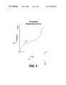
- FIG. 4is a graph (hue vs. saturation) of an image parameter adjustment curve employed in the digital enhancement system of FIG. 1;
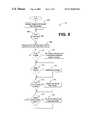
- FIG. 5is a flow chart of image enhancement logic executed by the digital image enhancement system of FIG. 1 .
- the image enhancement system 100includes a computer system 103 which comprises a processor 106 and a volatile/nonvolatile memory 109 , both of which are coupled to a local interface 113 .
- the local interface 113may include, for example, one or more data busses along with corresponding control busses, or local multiple processor network in the case of parallel processing systems.
- the computer system 103further comprises a display interface 116 , at least one input interface 119 , at least one network interface 123 , and one or more output interfaces 126 , all of which are also coupled to the local interface 113 .
- the volatile/nonvolatile memory 109may include, for example, random access memory (RAM), read-only memory (ROM), a hard drive, a combination compact disk drive with a compact disk, a combination floppy disk drive with a floppy disk, or other suitable data storage device.
- RAMrandom access memory
- ROMread-only memory
- a hard drivea combination compact disk drive with a compact disk
- a combination floppy disk drive with a floppy diskor other suitable data storage device.
- volatilerefers to those memory devices that do not maintain data during a loss of power
- nonvolatilerefers to those devices that maintain data during a loss of power.
- the image enhancement system 100also includes a display device 133 that is coupled to the local interface 113 through the video interface 116 .
- the display device 133may be any of a variety of well known display devices, such as, for example, a cathode ray tube (CRT), a liquid crystal display screen, a gas plasma-based flat panel display, indicator lights, light emitting diodes, and other display elements.
- CTRcathode ray tube
- LCDliquid crystal display screen
- gas plasma-based flat panel displaygas plasma-based flat panel display
- indicator lightslight emitting diodes, and other display elements.
- the image enhancement system 100features any one or a combination of several input devices, namely, a keyboard 136 , a mouse 139 , a microphone 143 , and a scanner 146 which are all coupled to the local interface 113 through the various input interfaces 119 .
- the local interface 113may be coupled to at least one external network(s) 149 such as a local area network (LAN), a wide area network (WAN), the Internet, or other such network via the network interface(s) 123 .
- the network interface(s) 123may comprise a suitable modem, interface card, or other suitable device.
- the computer system 103may receive and transmit data via external network(s) 149 by way of the network interfaces(s) 123 .
- the image enhancement system 100may further include audio speakers 153 , a printer 156 , or other output devices that are coupled to the local interface 113 via the output interfaces 126 .
- the image enhancement system 100also includes image enhancement logic 163 that is generally stored in the memory 109 along with a digital image 166 .
- a digital image 166is defined as an image that is embodied in digital data that may be accessed by the processor 106 and depicted on the display device 133 or generated by the printer 156 , or an image that is digitally encoded and stored in a computer memory.
- the processor 106When the image enhancement system 100 is operational, the processor 106 generally executes the image enhancement logic 163 .
- the image enhancement logic 163may be loaded from a nonvolatile memory source such as a hard drive to RAM where it is directly accessible to the processor 106 for various purposes as will be discussed.
- the image enhancement logic 163also includes logic to generate a user interface 169 on the display device 133 that provides a user with the means to manipulate various image controls that vary one or more image parameters of a digital image depicted thereon.
- the various image controlsinclude, but are not limited to, scenery, flesh tone, portrait attributes, sunrise/sunset, brightness, contrast, sharpness, color red, yellow, blue, green, and other similar controls.
- the user interface 169preferably facilitates the display of the digital image 166 .
- the digital image 166is stored in the memory 109 (FIG. 1) and accessed by the image enhancement logic 163 to be displayed on the display device 133 as part of the user interface 169 .
- the digital image 166may be downloaded to the memory 109 from the scanner 146 (FIG. 1) or via the network 149 (FIG. 1 ).
- the digital image 166may be downloaded into the memory 109 from a digital camera or other capture device through appropriate interfaces (not shown).
- the digital image 166may be stored on a nonvolatile memory device such as a floppy disk that is placed in a floppy disk drive of the computer system 103 (FIG. 1) and accessed by the processor 106 pursuant to the image enhancement logic 163 .
- a nonvolatile memory devicesuch as a floppy disk that is placed in a floppy disk drive of the computer system 103 (FIG. 1)
- accessing the digital image 166 as suchis an expedient known to those skilled in the art and not discussed in detail herein.
- the user interface 169further includes a number of menu items 206 on a menu bar 209 that can be manipulated using a cursor 213 .
- the cursor 213may be positioned over the menu items 206 using the mouse 139 , and then depressed using the button on the mouse 139 . This is referred to as “clicking” on a particular menu item 206 .
- clicking on a particular menu item 206a drop down menu falls from the menu bar 209 pertaining to the particular menu item 206 .
- the “controls” drop down menu 216lists a number of image controls 219 as shown.
- the image controls 219include, for example, but not limited to, default, lightness, sharpness, color, portrait, flesh tones, scenery, red, yellow, blue, green, split image, and de-split image or other like image controls.
- Associated with the lightness, sharpness, color, portrait, flesh tones, scenery, red, yellow, blue, and green image controls 219is at least one image parameter 223 that may be adjusted with an appropriate adjustment mechanism 226 .
- the adjustment mechanism 226includes, for example, a slide bar with adjustment pushbuttons at either end so that it may be easily manipulated by a user.
- the adjustment mechanism 226may also include any other device, such as a knob or other indicator.
- some image controls 219enable the adjustment of multiple image parameters 223 while some allow the adjustment of a single image parameter 223 .
- the same image parameter 223may be associated with one or more image controls.
- the “Scenery” image control 219generally causes an adjustment mechanism 226 to appear that facilitates the adjustment of the blue and green spectrums of the digital image 166 .
- These image parametersare associated with the scenery image control 219 as they relate to the blue of the sky and the green of most trees and foliage. These colors are generally stored in the memory of individuals as most people see them every day.
- the multiple image parameters that can be adjusted with respect to the blue and green spectrums of the scenery controlare the hue and saturation.
- the huerefers to the particular tint of the color itself, whereas the saturation refers to the amount or intensity of the color in the digital image 166 .
- the “Flesh Tones” image control 219When the user clicks on the “Flesh Tones” image control 219 , an adjustment mechanism appears that facilitates the adjustment of multiple image parameters, including the hue and saturation of the colors of flesh tones.
- the “Portrait” image control 219enables the adjustment of the sharpness or focus of the digital image 166 .
- the “Lightness” image control 219enables an adjustment mechanism 226 to adjust multiple image parameters, including the brightness and contrast of the digital image 166 .
- the “Sharpness” image control 219enables an adjustment mechanism 226 to adjust the image parameter 223 of the sharpness or focus of the digital image 166 , making it either softer or more distinct.
- the “Color” image controlenables an adjustment mechanism 226 that allows one to increase or reduce the amount of color displayed in the digital image 166 .
- the “Red,” “Yellow,” “Blue,” and “Green” image controls 219all enable adjustment mechanisms 226 to adjust the image parameters 223 of hue and saturation for each of these colors. Note that other colors may be included as well.
- controlsdrop down menu 216
- other image controls 219may be employed as well, such as a “sunrise/sunset” image control 223 that enables an adjustment mechanism 226 for multiple image parameters 223 , including the hue and saturation in the orange and red spectrums as well as the brightness of the digital image.
- a “Default” image control 219is included that allows a user to reestablish the original condition of the digital image 116 after it has been altered using any of the above image controls 219 .
- the usersimply clicks on the default image control 219 to reset the state of the digital image 166 accordingly.
- the “Split” and “De-split” image controls 219allow the user to cause multiple copies of the digital image 166 to appear that may be adjusted individually using any of the image controls 219 discussed above. For example, upon clicking on the “split image” image control 219 , three of the digital images 166 appear side by side. A user may highlight any one of the three digital images 166 by clicking thereon and then may alter the various image controls relative to the highlighted digital image 166 . The highlighted digital image 166 becomes the only digital image if one clicks on the “De-split Image” image control 219 , accordingly.
- the adjustment of the image parameters according to the present inventionprovides distinct advantages.
- a usercan alter an image to change its appearance to better suit a predefined purpose of the user.
- certain colors or other attributes of the digital image 166are preferably enhanced or diminished to make them easier to interpret by users, etc.
- the image controls 219are easily manipulated by the average user.
- FIG. 4shown is a graph 230 of a multiple parameter adjustment curve 233 according to an embodiment of the present invention.
- the multiple parameter adjustment curve 233illustrates the adjustment, for example, of two image parameters 223 that are associated with a single adjustment mechanism 226 (FIG. 3 ).
- the position of the adjustment mechanism 226corresponds to a particular position on the multiple parameter adjustment curve 233 .
- the multiple parameter adjustment curve 233may be stored in the memory 109 as part of the image enhancement logic 163 .
- the particular magnitude or other quality of the relevant image parameter 223may be adjusted in the digital image (FIG. 2) by drawing an association between the current position of the respective adjustment parameter 226 and the same position on the multiple parameter adjustment curve 233 .
- the image enhancement logic 163is generally stored on the memory 109 and is executed by the processor 106 , although it may also be implemented in hardware, etc.
- the image enhancement logic 163generally controls the alteration of the digital image 166 based upon the manipulation of the various components of the user interface 169 as discussed previously.
- the image enhancement logic 163causes the user interface 169 (FIG. 2) to be displayed on the display device 133 (FIG. 1 ). Thereafter, in block 306 , the image enhancement logic 163 determines whether the user has clicked on the “controls” menu item 206 on the menu bar 209 (FIG. 3 ). If such is the case, then the image enhancement logic 163 progresses to block 309 in which the “controls” drop down menu 216 (FIG. 3) is displayed on the user interface 169 as shown in FIG. 3 . Thereafter, in block 313 , if the user clicks on the default image control 219 (FIG. 3 ), then the image enhancement logic 163 moves to block 316 in which the image parameters 223 (FIG. 3) of the current active digital image 166 (FIG. 3) are set to default settings corresponding to the digital image 166 as originally displayed on the user interface 169 .
- the image enhancement logic 163moves on to block 319 in which it is determined whether the user has clicked the “Split” or “De-split” image controls 219 . If such is the case, then the image enhancement logic 163 moves to block 323 in which the digital image 166 (FIG. 2) is Split or De-split between a single and multiple images as discussed above. After performing the functionality of block 323 or, if no “Split” or “De-split” image control 219 has been clicked in block 319 , then the image enhancement logic 163 moves on to block 326 .
- the image enhancement logic 163detects whether the user has clicked on any of the remaining image controls 219 . If so, then the image enhancement logic 163 moves to block 329 . Otherwise, the image enhancement logic progresses to block 333 . In block 329 , the appropriate adjustment mechanism 226 (FIG. 3) associated with the particular image parameter 223 that was activated by clicking on the image control 219 is displayed on the user interface 169 . Thereafter, the image enhancement logic 163 moves to block 333 accordingly.
- the image enhancement logic 163determines whether an active image mechanism 226 has been adjusted by the user by manipulating a corresponding adjustment mechanism. If so, then the image enhancement logic 163 progresses to block 336 in which the corresponding image parameter 223 is adjusted accordingly. Otherwise, the image enhancement logic 163 reverts back to block 313 as shown. Note then that the image enhancement logic 163 will continually loop through blocks 313 , 319 , 326 , and 333 until the user performs one of the actions associated therewith. In this manner, the user may adjust the nature of the digital image 166 according to the dictates of the user's taste. The user may exit the “controls” drop down menu by clicking on another button or other mechanism on the user interface 169 .
- the image enhancement logic 163can be implemented in hardware, software, firmware, or a combination thereof. If implemented in hardware, the image enhancement logic 163 may comprise a dedicated circuit with any or a combination of the following technologies, which are all well known in the art: a discrete logic circuit(s) having logic gates for implementing logic functions upon data signals, an application specific integrated circuit having appropriate logic gates, a programmable gate array(s) (PGA), a fully programmable gate array (FPGA), etc.
- PGAprogrammable gate array
- FPGAfully programmable gate array
- each blockrepresents a module, segment, or portion of code, which comprises one or more executable instructions for implementing the specified logical function(s).
- the functions noted in the blocksmay occur out of the order noted in FIG. 5 .
- two blocks shown in succession in FIG. 5may in fact be executed substantially concurrently or the blocks may sometimes be executed in the reverse order, depending upon the functionality involved, as will be further clarified hereinbelow.
- the software embodiment of the image enhancement logic 163comprises an ordered listing of executable instructions for implementing logical functions, can be embodied in any computer-readable medium for use by or in connection with an instruction execution system, apparatus, or device, such as a computer-based system, processor-containing system, or other system that can fetch the instructions from the instruction execution system, apparatus, or device and execute the instructions.
- a “computer-readable medium”can be any means that can contain, store, communicate, propagate, or transport the program for use by or in connection with the instruction execution system, apparatus, or device.
- the computer readable mediumcan be, for example but not limited to, an electronic, magnetic, optical, electromagnetic, infrared, or semiconductor system, apparatus, device, or propagation medium.
- the computer-readable mediumcould even be paper or another suitable medium upon which the program is printed, as the program can be electronically captured, via for instance optical scanning of the paper or other medium, then compiled, interpreted or otherwise processed in a suitable manner if necessary, and then stored in a computer memory.
Landscapes
- Engineering & Computer Science (AREA)
- Multimedia (AREA)
- Signal Processing (AREA)
- Image Processing (AREA)
- Apparatus For Radiation Diagnosis (AREA)
- Facsimile Image Signal Circuits (AREA)
Abstract
Description
Claims (12)
Priority Applications (2)
| Application Number | Priority Date | Filing Date | Title |
|---|---|---|---|
| US09/429,145US6792158B1 (en) | 1999-10-28 | 1999-10-28 | System and method for image enhancement |
| EP00112170AEP1096786A3 (en) | 1999-10-28 | 2000-06-06 | System and method for image enhancement |
Applications Claiming Priority (1)
| Application Number | Priority Date | Filing Date | Title |
|---|---|---|---|
| US09/429,145US6792158B1 (en) | 1999-10-28 | 1999-10-28 | System and method for image enhancement |
Publications (1)
| Publication Number | Publication Date |
|---|---|
| US6792158B1true US6792158B1 (en) | 2004-09-14 |
Family
ID=23701985
Family Applications (1)
| Application Number | Title | Priority Date | Filing Date |
|---|---|---|---|
| US09/429,145Expired - LifetimeUS6792158B1 (en) | 1999-10-28 | 1999-10-28 | System and method for image enhancement |
Country Status (2)
| Country | Link |
|---|---|
| US (1) | US6792158B1 (en) |
| EP (1) | EP1096786A3 (en) |
Cited By (9)
| Publication number | Priority date | Publication date | Assignee | Title |
|---|---|---|---|---|
| US20060002632A1 (en)* | 2004-06-30 | 2006-01-05 | Accuray, Inc. | Motion field generation for non-rigid image registration |
| US20060002615A1 (en)* | 2004-06-30 | 2006-01-05 | Accuray, Inc. | Image enhancement method and system for fiducial-less tracking of treatment targets |
| US20060002630A1 (en)* | 2004-06-30 | 2006-01-05 | Accuray, Inc. | Fiducial-less tracking with non-rigid image registration |
| US20060002631A1 (en)* | 2004-06-30 | 2006-01-05 | Accuray, Inc. | ROI selection in image registration |
| US20060002601A1 (en)* | 2004-06-30 | 2006-01-05 | Accuray, Inc. | DRR generation using a non-linear attenuation model |
| US20060170707A1 (en)* | 2001-10-24 | 2006-08-03 | Nik Software, Inc. | Overlayed Graphic User Interface and Method for Image Processing |
| US7330578B2 (en) | 2005-06-23 | 2008-02-12 | Accuray Inc. | DRR generation and enhancement using a dedicated graphics device |
| US20100039448A1 (en)* | 2001-10-24 | 2010-02-18 | Nik Software, Inc. | Distortion of Digital Images Using Spatial Offsets |
| US10048824B2 (en)* | 2013-04-26 | 2018-08-14 | Samsung Electronics Co., Ltd. | User terminal device and display method thereof |
Families Citing this family (2)
| Publication number | Priority date | Publication date | Assignee | Title |
|---|---|---|---|---|
| US6741262B1 (en)* | 2000-05-12 | 2004-05-25 | Electronics For Imaging, Inc. | Expert color management settings method and interface |
| US20090290038A1 (en) | 2007-08-06 | 2009-11-26 | Nikon Corporation | Electronic camera |
Citations (13)
| Publication number | Priority date | Publication date | Assignee | Title |
|---|---|---|---|---|
| US4833625A (en)* | 1986-07-09 | 1989-05-23 | University Of Arizona | Image viewing station for picture archiving and communications systems (PACS) |
| US5109348A (en)* | 1987-09-14 | 1992-04-28 | Visual Information Technologies, Inc. | High speed image processing computer |
| US5257097A (en)* | 1991-09-27 | 1993-10-26 | Eastman Kodak Company | Method and apparatus for selective interception of a graphics rendering operation for effecting image data modification |
| US5307180A (en)* | 1991-12-18 | 1994-04-26 | Xerox Corporation | Method and apparatus for controlling the processing of digital image signals |
| US5563720A (en)* | 1992-07-17 | 1996-10-08 | International Business Machines Corporation | Expert system for image enhancement |
| US5568571A (en)* | 1992-12-14 | 1996-10-22 | University Microfilms, Inc. | Image enhancement system |
| US5636036A (en)* | 1987-02-27 | 1997-06-03 | Ashbey; James A. | Interactive video system having frame recall dependent upon user input and current displayed image |
| US5652663A (en) | 1994-07-29 | 1997-07-29 | Polaroid Corporation | Preview buffer for electronic scanner |
| US5652851A (en)* | 1993-07-21 | 1997-07-29 | Xerox Corporation | User interface technique for producing a second image in the spatial context of a first image using a model-based operation |
| US5828461A (en) | 1995-11-17 | 1998-10-27 | Fuji Photo Film Co., Ltd. | Method and apparatus for converting original image data to density data for forming an image on photosensitive material and for displaying an image on a monitor |
| US5844542A (en) | 1995-07-11 | 1998-12-01 | Fuji Xerox Co., Ltd. | Image processing apparatus and method with multi-dimensional display of image adjustment levels |
| US5930009A (en) | 1993-05-21 | 1999-07-27 | Mitsubishi Denki Kabushiki Kaisha | System and method for adjusting color |
| US6690356B2 (en)* | 1992-12-21 | 2004-02-10 | Apple Computer, Inc. | Method and apparatus for providing visual feedback during manipulation of text on a computer screen |
- 1999
- 1999-10-28USUS09/429,145patent/US6792158B1/ennot_activeExpired - Lifetime
- 2000
- 2000-06-06EPEP00112170Apatent/EP1096786A3/ennot_activeWithdrawn
Patent Citations (13)
| Publication number | Priority date | Publication date | Assignee | Title |
|---|---|---|---|---|
| US4833625A (en)* | 1986-07-09 | 1989-05-23 | University Of Arizona | Image viewing station for picture archiving and communications systems (PACS) |
| US5636036A (en)* | 1987-02-27 | 1997-06-03 | Ashbey; James A. | Interactive video system having frame recall dependent upon user input and current displayed image |
| US5109348A (en)* | 1987-09-14 | 1992-04-28 | Visual Information Technologies, Inc. | High speed image processing computer |
| US5257097A (en)* | 1991-09-27 | 1993-10-26 | Eastman Kodak Company | Method and apparatus for selective interception of a graphics rendering operation for effecting image data modification |
| US5307180A (en)* | 1991-12-18 | 1994-04-26 | Xerox Corporation | Method and apparatus for controlling the processing of digital image signals |
| US5563720A (en)* | 1992-07-17 | 1996-10-08 | International Business Machines Corporation | Expert system for image enhancement |
| US5568571A (en)* | 1992-12-14 | 1996-10-22 | University Microfilms, Inc. | Image enhancement system |
| US6690356B2 (en)* | 1992-12-21 | 2004-02-10 | Apple Computer, Inc. | Method and apparatus for providing visual feedback during manipulation of text on a computer screen |
| US5930009A (en) | 1993-05-21 | 1999-07-27 | Mitsubishi Denki Kabushiki Kaisha | System and method for adjusting color |
| US5652851A (en)* | 1993-07-21 | 1997-07-29 | Xerox Corporation | User interface technique for producing a second image in the spatial context of a first image using a model-based operation |
| US5652663A (en) | 1994-07-29 | 1997-07-29 | Polaroid Corporation | Preview buffer for electronic scanner |
| US5844542A (en) | 1995-07-11 | 1998-12-01 | Fuji Xerox Co., Ltd. | Image processing apparatus and method with multi-dimensional display of image adjustment levels |
| US5828461A (en) | 1995-11-17 | 1998-10-27 | Fuji Photo Film Co., Ltd. | Method and apparatus for converting original image data to density data for forming an image on photosensitive material and for displaying an image on a monitor |
Non-Patent Citations (2)
| Title |
|---|
| Bradley, John, "XV Interactive Image Display for the X Window System", (XP002228397), pp. 33-44, Published on Dec. 29, 1994. |
| European Search Report, Application No. EP 00 11 2170, dated Feb. 10, 2003. |
Cited By (30)
| Publication number | Priority date | Publication date | Assignee | Title |
|---|---|---|---|---|
| US7602968B2 (en) | 2001-10-24 | 2009-10-13 | Nik Software, Inc. | Overlaid graphical user interface and method for image processing |
| US10140682B2 (en) | 2001-10-24 | 2018-11-27 | Google Llc | Distortion of digital images using spatial offsets from image reference points |
| US9786031B2 (en) | 2001-10-24 | 2017-10-10 | Google Inc. | Distortion of digital images using spatial offsets from image reference points |
| US9471998B2 (en) | 2001-10-24 | 2016-10-18 | Google Inc. | Distortion of digital images using spatial offsets from image reference points |
| US9008420B2 (en) | 2001-10-24 | 2015-04-14 | Google Inc. | Distortion of digital images using spatial offsets from image reference points |
| US20060170707A1 (en)* | 2001-10-24 | 2006-08-03 | Nik Software, Inc. | Overlayed Graphic User Interface and Method for Image Processing |
| US8625925B2 (en) | 2001-10-24 | 2014-01-07 | Google Inc. | Distortion of digital images using spatial offsets from image reference points |
| US8064725B2 (en) | 2001-10-24 | 2011-11-22 | Nik Software, Inc. | Distortion of digital images using spatial offsets |
| US7970233B2 (en) | 2001-10-24 | 2011-06-28 | Nik Software, Inc. | Distortion of digital images using spatial offsets from image reference points |
| US20100303379A1 (en)* | 2001-10-24 | 2010-12-02 | Nik Software, Inc. | Distortion of digital images using spatial offsets from image reference points |
| US20100039448A1 (en)* | 2001-10-24 | 2010-02-18 | Nik Software, Inc. | Distortion of Digital Images Using Spatial Offsets |
| US20100027908A1 (en)* | 2001-10-24 | 2010-02-04 | Nik Software, Inc. | Distortion of Digital Images Using Spatial Offsets From Image Reference Points |
| US7327865B2 (en) | 2004-06-30 | 2008-02-05 | Accuray, Inc. | Fiducial-less tracking with non-rigid image registration |
| US20060002601A1 (en)* | 2004-06-30 | 2006-01-05 | Accuray, Inc. | DRR generation using a non-linear attenuation model |
| US7505617B2 (en) | 2004-06-30 | 2009-03-17 | Accuray, Inc. | Fiducial-less tracking with non-rigid image registration |
| US20090091567A1 (en)* | 2004-06-30 | 2009-04-09 | Accuray, Inc. | Image enhancement method and system for fiducial-less tracking of treatment targets |
| US7522779B2 (en) | 2004-06-30 | 2009-04-21 | Accuray, Inc. | Image enhancement method and system for fiducial-less tracking of treatment targets |
| US20080159612A1 (en)* | 2004-06-30 | 2008-07-03 | Dongshan Fu | DRR generation using a non-linear attenuation model |
| US20080101673A1 (en)* | 2004-06-30 | 2008-05-01 | Dongshan Fu | Fiducial-less tracking with non-rigid image registration |
| US7366278B2 (en) | 2004-06-30 | 2008-04-29 | Accuray, Inc. | DRR generation using a non-linear attenuation model |
| US7840093B2 (en) | 2004-06-30 | 2010-11-23 | Accuray, Inc. | Image enhancement method and system for fiducial-less tracking of treatment targets |
| US20060002615A1 (en)* | 2004-06-30 | 2006-01-05 | Accuray, Inc. | Image enhancement method and system for fiducial-less tracking of treatment targets |
| US20060002630A1 (en)* | 2004-06-30 | 2006-01-05 | Accuray, Inc. | Fiducial-less tracking with non-rigid image registration |
| US20060002632A1 (en)* | 2004-06-30 | 2006-01-05 | Accuray, Inc. | Motion field generation for non-rigid image registration |
| US7231076B2 (en) | 2004-06-30 | 2007-06-12 | Accuray, Inc. | ROI selection in image registration |
| US7426318B2 (en) | 2004-06-30 | 2008-09-16 | Accuray, Inc. | Motion field generation for non-rigid image registration |
| US20060002631A1 (en)* | 2004-06-30 | 2006-01-05 | Accuray, Inc. | ROI selection in image registration |
| US7330578B2 (en) | 2005-06-23 | 2008-02-12 | Accuray Inc. | DRR generation and enhancement using a dedicated graphics device |
| US20080069422A1 (en)* | 2005-06-23 | 2008-03-20 | Bai Wang | DRR generation and enhancement using a dedicated graphics device |
| US10048824B2 (en)* | 2013-04-26 | 2018-08-14 | Samsung Electronics Co., Ltd. | User terminal device and display method thereof |
Also Published As
| Publication number | Publication date |
|---|---|
| EP1096786A2 (en) | 2001-05-02 |
| EP1096786A3 (en) | 2003-03-26 |
Similar Documents
| Publication | Publication Date | Title |
|---|---|---|
| US7853078B2 (en) | Setup-screen display controlling apparatus, server apparatus, image processing system, printing apparatus, image pickup apparatus, display apparatus, setup-screen display controlling method, program, and data structure | |
| US6128013A (en) | User interface for an image capture device | |
| US6750890B1 (en) | Method and device for displaying a history of image processing information | |
| US6587129B1 (en) | User interface for image acquisition devices | |
| US5898436A (en) | Graphical user interface for digital image editing | |
| US7317439B2 (en) | Electronic apparatus and recording medium therefor | |
| US20110205397A1 (en) | Portable imaging device having display with improved visibility under adverse conditions | |
| US6469747B1 (en) | Parabolic mixer for video signals | |
| US6623119B2 (en) | System and method for modifying image-processing software in response to visual test results | |
| CN101273624A (en) | Compensation for improperly exposed areas in digital images | |
| US6792158B1 (en) | System and method for image enhancement | |
| US7586499B1 (en) | Method and apparatus for adjusting the color of a digital image | |
| US8064716B2 (en) | Apparatus and methods for enhancing digital images | |
| JP4123724B2 (en) | Image processing program, computer-readable recording medium storing image processing program, image processing apparatus, and image processing method | |
| CN101019416A (en) | Imaging apparatus | |
| KR20230041648A (en) | Multi-frame depth-based multi-camera relighting of images | |
| US10621769B2 (en) | Simplified lighting compositing | |
| US20040201726A1 (en) | Digital camera and method for balancing color in a digital image | |
| JP2002281312A (en) | Device, method and program for processing image | |
| CN101010930B (en) | A method and system for generating a color scheme for a mobile communication device | |
| US20050094891A1 (en) | System and method for tone composition | |
| JP4758999B2 (en) | Image processing program, image processing method, and image processing apparatus | |
| CN112465721B (en) | Image correction method and device, mobile terminal and storage medium | |
| WO2022262848A1 (en) | Image processing method and apparatus, and electronic device | |
| US6072605A (en) | Transforms for digital images in linear form |
Legal Events
| Date | Code | Title | Description |
|---|---|---|---|
| AS | Assignment | Owner name:HEWLETT-PACKARD COMPANY, COLORADO Free format text:ASSIGNMENT OF ASSIGNORS INTEREST;ASSIGNOR:BRUMLEY, WILSON E.;REEL/FRAME:010615/0088 Effective date:19991028 | |
| AS | Assignment | Owner name:HEWLETT-PACKARD DEVELOPMENT COMPANY L.P., TEXAS Free format text:ASSIGNMENT OF ASSIGNORS INTEREST;ASSIGNOR:HEWLETT-PACKARD COMPANY;REEL/FRAME:014061/0492 Effective date:20030926 Owner name:HEWLETT-PACKARD DEVELOPMENT COMPANY L.P.,TEXAS Free format text:ASSIGNMENT OF ASSIGNORS INTEREST;ASSIGNOR:HEWLETT-PACKARD COMPANY;REEL/FRAME:014061/0492 Effective date:20030926 | |
| STCF | Information on status: patent grant | Free format text:PATENTED CASE | |
| FPAY | Fee payment | Year of fee payment:4 | |
| REMI | Maintenance fee reminder mailed | ||
| FPAY | Fee payment | Year of fee payment:8 | |
| FEPP | Fee payment procedure | Free format text:PAYOR NUMBER ASSIGNED (ORIGINAL EVENT CODE: ASPN); ENTITY STATUS OF PATENT OWNER: LARGE ENTITY | |
| AS | Assignment | Owner name:LIBRE HOLDINGS, INC., MASSACHUSETTS Free format text:ASSIGNMENT OF ASSIGNORS INTEREST;ASSIGNOR:HEWLETT-PACKARD DEVELOPMENT COMPANY, L.P.;REEL/FRAME:029431/0368 Effective date:20121105 | |
| FPAY | Fee payment | Year of fee payment:12 |